EP3632532A1 - Apparatus and method for reaction - Google Patents
Apparatus and method for reaction Download PDFInfo
- Publication number
- EP3632532A1 EP3632532A1 EP18809959.2A EP18809959A EP3632532A1 EP 3632532 A1 EP3632532 A1 EP 3632532A1 EP 18809959 A EP18809959 A EP 18809959A EP 3632532 A1 EP3632532 A1 EP 3632532A1
- Authority
- EP
- European Patent Office
- Prior art keywords
- reaction
- reaction vessel
- solution
- raw material
- solutions
- Prior art date
- Legal status (The legal status is an assumption and is not a legal conclusion. Google has not performed a legal analysis and makes no representation as to the accuracy of the status listed.)
- Withdrawn
Links
- 238000006243 chemical reaction Methods 0.000 title claims abstract description 152
- 238000000034 method Methods 0.000 title claims abstract description 24
- 239000000243 solution Substances 0.000 claims abstract description 165
- 238000002347 injection Methods 0.000 claims abstract description 75
- 239000007924 injection Substances 0.000 claims abstract description 75
- 238000003756 stirring Methods 0.000 claims abstract description 34
- 239000006182 cathode active material Substances 0.000 claims abstract description 24
- 238000000975 co-precipitation Methods 0.000 claims abstract description 23
- WHXSMMKQMYFTQS-UHFFFAOYSA-N Lithium Chemical compound [Li] WHXSMMKQMYFTQS-UHFFFAOYSA-N 0.000 claims abstract description 22
- 229910052744 lithium Inorganic materials 0.000 claims abstract description 22
- 239000002994 raw material Substances 0.000 claims abstract description 20
- 229910052751 metal Inorganic materials 0.000 claims description 55
- 239000002184 metal Substances 0.000 claims description 55
- 239000002243 precursor Substances 0.000 claims description 31
- HEMHJVSKTPXQMS-UHFFFAOYSA-M Sodium hydroxide Chemical compound [OH-].[Na+] HEMHJVSKTPXQMS-UHFFFAOYSA-M 0.000 claims description 24
- 238000002156 mixing Methods 0.000 claims description 22
- 229910003618 NixCoyMn1-x-y(OH)2 Inorganic materials 0.000 claims description 16
- KFDQGLPGKXUTMZ-UHFFFAOYSA-N [Mn].[Co].[Ni] Chemical compound [Mn].[Co].[Ni] KFDQGLPGKXUTMZ-UHFFFAOYSA-N 0.000 claims description 9
- VHUUQVKOLVNVRT-UHFFFAOYSA-N Ammonium hydroxide Chemical compound [NH4+].[OH-] VHUUQVKOLVNVRT-UHFFFAOYSA-N 0.000 claims description 8
- 239000011572 manganese Substances 0.000 claims description 6
- 238000003780 insertion Methods 0.000 claims description 4
- 230000037431 insertion Effects 0.000 claims description 4
- -1 nickel-cobalt-aluminum Chemical compound 0.000 claims description 4
- 229910052748 manganese Inorganic materials 0.000 claims description 3
- 239000000203 mixture Substances 0.000 claims description 3
- 229910052759 nickel Inorganic materials 0.000 claims description 3
- 239000003054 catalyst Substances 0.000 abstract description 5
- 239000002245 particle Substances 0.000 description 14
- 238000004519 manufacturing process Methods 0.000 description 13
- 230000000694 effects Effects 0.000 description 11
- 230000001965 increasing effect Effects 0.000 description 11
- 238000004088 simulation Methods 0.000 description 10
- PXHVJJICTQNCMI-UHFFFAOYSA-N Nickel Chemical compound [Ni] PXHVJJICTQNCMI-UHFFFAOYSA-N 0.000 description 8
- 239000012697 Mn precursor Substances 0.000 description 5
- 229910018060 Ni-Co-Mn Inorganic materials 0.000 description 5
- 229910018209 Ni—Co—Mn Inorganic materials 0.000 description 5
- 238000010586 diagram Methods 0.000 description 5
- 230000008569 process Effects 0.000 description 5
- 230000035484 reaction time Effects 0.000 description 5
- 238000002360 preparation method Methods 0.000 description 4
- 230000002708 enhancing effect Effects 0.000 description 3
- XLYOFNOQVPJJNP-UHFFFAOYSA-N water Substances O XLYOFNOQVPJJNP-UHFFFAOYSA-N 0.000 description 3
- QGZKDVFQNNGYKY-UHFFFAOYSA-N Ammonia Chemical compound N QGZKDVFQNNGYKY-UHFFFAOYSA-N 0.000 description 2
- IJGRMHOSHXDMSA-UHFFFAOYSA-N Atomic nitrogen Chemical compound N#N IJGRMHOSHXDMSA-UHFFFAOYSA-N 0.000 description 2
- 239000002738 chelating agent Substances 0.000 description 2
- 239000013078 crystal Substances 0.000 description 2
- 150000002500 ions Chemical class 0.000 description 2
- 239000011148 porous material Substances 0.000 description 2
- 239000011164 primary particle Substances 0.000 description 2
- 238000010298 pulverizing process Methods 0.000 description 2
- 238000010926 purge Methods 0.000 description 2
- 230000009467 reduction Effects 0.000 description 2
- 230000006641 stabilisation Effects 0.000 description 2
- 238000011105 stabilization Methods 0.000 description 2
- 229910002993 LiMnO2 Inorganic materials 0.000 description 1
- 229910013100 LiNix Inorganic materials 0.000 description 1
- 229910002097 Lithium manganese(III,IV) oxide Inorganic materials 0.000 description 1
- PWHULOQIROXLJO-UHFFFAOYSA-N Manganese Chemical compound [Mn] PWHULOQIROXLJO-UHFFFAOYSA-N 0.000 description 1
- 229910018058 Ni-Co-Al Inorganic materials 0.000 description 1
- 229910018144 Ni—Co—Al Inorganic materials 0.000 description 1
- 238000007792 addition Methods 0.000 description 1
- 229910021529 ammonia Inorganic materials 0.000 description 1
- 235000011114 ammonium hydroxide Nutrition 0.000 description 1
- 239000003637 basic solution Substances 0.000 description 1
- 230000015572 biosynthetic process Effects 0.000 description 1
- 230000008859 change Effects 0.000 description 1
- 150000001805 chlorine compounds Chemical class 0.000 description 1
- 229910017052 cobalt Inorganic materials 0.000 description 1
- 239000010941 cobalt Substances 0.000 description 1
- GUTLYIVDDKVIGB-UHFFFAOYSA-N cobalt atom Chemical compound [Co] GUTLYIVDDKVIGB-UHFFFAOYSA-N 0.000 description 1
- IVMYJDGYRUAWML-UHFFFAOYSA-N cobalt(ii) oxide Chemical class [Co]=O IVMYJDGYRUAWML-UHFFFAOYSA-N 0.000 description 1
- 230000000052 comparative effect Effects 0.000 description 1
- 238000009833 condensation Methods 0.000 description 1
- 230000005494 condensation Effects 0.000 description 1
- 230000008878 coupling Effects 0.000 description 1
- 238000010168 coupling process Methods 0.000 description 1
- 238000005859 coupling reaction Methods 0.000 description 1
- 238000007599 discharging Methods 0.000 description 1
- 238000005516 engineering process Methods 0.000 description 1
- 230000001747 exhibiting effect Effects 0.000 description 1
- 230000007062 hydrolysis Effects 0.000 description 1
- 238000006460 hydrolysis reaction Methods 0.000 description 1
- 150000004679 hydroxides Chemical class 0.000 description 1
- 238000009434 installation Methods 0.000 description 1
- AMWRITDGCCNYAT-UHFFFAOYSA-L manganese oxide Inorganic materials [Mn].O[Mn]=O.O[Mn]=O AMWRITDGCCNYAT-UHFFFAOYSA-L 0.000 description 1
- PPNAOCWZXJOHFK-UHFFFAOYSA-N manganese(2+);oxygen(2-) Chemical class [O-2].[Mn+2] PPNAOCWZXJOHFK-UHFFFAOYSA-N 0.000 description 1
- 239000000463 material Substances 0.000 description 1
- 235000012054 meals Nutrition 0.000 description 1
- 238000012986 modification Methods 0.000 description 1
- 230000004048 modification Effects 0.000 description 1
- 229910000480 nickel oxide Inorganic materials 0.000 description 1
- 150000004767 nitrides Chemical class 0.000 description 1
- 229910052757 nitrogen Inorganic materials 0.000 description 1
- 230000001151 other effect Effects 0.000 description 1
- GNRSAWUEBMWBQH-UHFFFAOYSA-N oxonickel Chemical class [Ni]=O GNRSAWUEBMWBQH-UHFFFAOYSA-N 0.000 description 1
- 239000000843 powder Substances 0.000 description 1
- 230000001376 precipitating effect Effects 0.000 description 1
- 238000007789 sealing Methods 0.000 description 1
- 238000003980 solgel method Methods 0.000 description 1
- 239000007787 solid Substances 0.000 description 1
- 229910052596 spinel Inorganic materials 0.000 description 1
- 239000011029 spinel Substances 0.000 description 1
- 238000006467 substitution reaction Methods 0.000 description 1
- 230000001629 suppression Effects 0.000 description 1
- 150000003568 thioethers Chemical class 0.000 description 1
Images








Classifications
-
- B—PERFORMING OPERATIONS; TRANSPORTING
- B01—PHYSICAL OR CHEMICAL PROCESSES OR APPARATUS IN GENERAL
- B01J—CHEMICAL OR PHYSICAL PROCESSES, e.g. CATALYSIS OR COLLOID CHEMISTRY; THEIR RELEVANT APPARATUS
- B01J19/00—Chemical, physical or physico-chemical processes in general; Their relevant apparatus
- B01J19/0053—Details of the reactor
- B01J19/0066—Stirrers
-
- B—PERFORMING OPERATIONS; TRANSPORTING
- B01—PHYSICAL OR CHEMICAL PROCESSES OR APPARATUS IN GENERAL
- B01J—CHEMICAL OR PHYSICAL PROCESSES, e.g. CATALYSIS OR COLLOID CHEMISTRY; THEIR RELEVANT APPARATUS
- B01J4/00—Feed or outlet devices; Feed or outlet control devices
- B01J4/001—Feed or outlet devices as such, e.g. feeding tubes
- B01J4/002—Nozzle-type elements
-
- B—PERFORMING OPERATIONS; TRANSPORTING
- B01—PHYSICAL OR CHEMICAL PROCESSES OR APPARATUS IN GENERAL
- B01F—MIXING, e.g. DISSOLVING, EMULSIFYING OR DISPERSING
- B01F23/00—Mixing according to the phases to be mixed, e.g. dispersing or emulsifying
- B01F23/40—Mixing liquids with liquids; Emulsifying
- B01F23/43—Mixing liquids with liquids; Emulsifying using driven stirrers
-
- B—PERFORMING OPERATIONS; TRANSPORTING
- B01—PHYSICAL OR CHEMICAL PROCESSES OR APPARATUS IN GENERAL
- B01F—MIXING, e.g. DISSOLVING, EMULSIFYING OR DISPERSING
- B01F23/00—Mixing according to the phases to be mixed, e.g. dispersing or emulsifying
- B01F23/40—Mixing liquids with liquids; Emulsifying
- B01F23/43—Mixing liquids with liquids; Emulsifying using driven stirrers
- B01F23/431—Mixing liquids with liquids; Emulsifying using driven stirrers the liquids being introduced from the outside through or along the axis of a rotating stirrer, e.g. the stirrer rotating due to the reaction of the introduced liquid
-
- B—PERFORMING OPERATIONS; TRANSPORTING
- B01—PHYSICAL OR CHEMICAL PROCESSES OR APPARATUS IN GENERAL
- B01F—MIXING, e.g. DISSOLVING, EMULSIFYING OR DISPERSING
- B01F25/00—Flow mixers; Mixers for falling materials, e.g. solid particles
- B01F25/20—Jet mixers, i.e. mixers using high-speed fluid streams
- B01F25/21—Jet mixers, i.e. mixers using high-speed fluid streams with submerged injectors, e.g. nozzles, for injecting high-pressure jets into a large volume or into mixing chambers
-
- B—PERFORMING OPERATIONS; TRANSPORTING
- B01—PHYSICAL OR CHEMICAL PROCESSES OR APPARATUS IN GENERAL
- B01F—MIXING, e.g. DISSOLVING, EMULSIFYING OR DISPERSING
- B01F27/00—Mixers with rotary stirring devices in fixed receptacles; Kneaders
- B01F27/05—Stirrers
- B01F27/11—Stirrers characterised by the configuration of the stirrers
- B01F27/113—Propeller-shaped stirrers for producing an axial flow, e.g. shaped like a ship or aircraft propeller
-
- B—PERFORMING OPERATIONS; TRANSPORTING
- B01—PHYSICAL OR CHEMICAL PROCESSES OR APPARATUS IN GENERAL
- B01F—MIXING, e.g. DISSOLVING, EMULSIFYING OR DISPERSING
- B01F27/00—Mixers with rotary stirring devices in fixed receptacles; Kneaders
- B01F27/05—Stirrers
- B01F27/11—Stirrers characterised by the configuration of the stirrers
- B01F27/19—Stirrers with two or more mixing elements mounted in sequence on the same axis
- B01F27/191—Stirrers with two or more mixing elements mounted in sequence on the same axis with similar elements
-
- B—PERFORMING OPERATIONS; TRANSPORTING
- B01—PHYSICAL OR CHEMICAL PROCESSES OR APPARATUS IN GENERAL
- B01F—MIXING, e.g. DISSOLVING, EMULSIFYING OR DISPERSING
- B01F27/00—Mixers with rotary stirring devices in fixed receptacles; Kneaders
- B01F27/80—Mixers with rotary stirring devices in fixed receptacles; Kneaders with stirrers rotating about a substantially vertical axis
- B01F27/86—Mixers with rotary stirring devices in fixed receptacles; Kneaders with stirrers rotating about a substantially vertical axis co-operating with deflectors or baffles fixed to the receptacle
-
- B—PERFORMING OPERATIONS; TRANSPORTING
- B01—PHYSICAL OR CHEMICAL PROCESSES OR APPARATUS IN GENERAL
- B01F—MIXING, e.g. DISSOLVING, EMULSIFYING OR DISPERSING
- B01F27/00—Mixers with rotary stirring devices in fixed receptacles; Kneaders
- B01F27/80—Mixers with rotary stirring devices in fixed receptacles; Kneaders with stirrers rotating about a substantially vertical axis
- B01F27/90—Mixers with rotary stirring devices in fixed receptacles; Kneaders with stirrers rotating about a substantially vertical axis with paddles or arms
- B01F27/906—Mixers with rotary stirring devices in fixed receptacles; Kneaders with stirrers rotating about a substantially vertical axis with paddles or arms with fixed axis
-
- B—PERFORMING OPERATIONS; TRANSPORTING
- B01—PHYSICAL OR CHEMICAL PROCESSES OR APPARATUS IN GENERAL
- B01F—MIXING, e.g. DISSOLVING, EMULSIFYING OR DISPERSING
- B01F27/00—Mixers with rotary stirring devices in fixed receptacles; Kneaders
- B01F27/80—Mixers with rotary stirring devices in fixed receptacles; Kneaders with stirrers rotating about a substantially vertical axis
- B01F27/91—Mixers with rotary stirring devices in fixed receptacles; Kneaders with stirrers rotating about a substantially vertical axis with propellers
-
- B—PERFORMING OPERATIONS; TRANSPORTING
- B01—PHYSICAL OR CHEMICAL PROCESSES OR APPARATUS IN GENERAL
- B01F—MIXING, e.g. DISSOLVING, EMULSIFYING OR DISPERSING
- B01F35/00—Accessories for mixers; Auxiliary operations or auxiliary devices; Parts or details of general application
- B01F35/20—Measuring; Control or regulation
- B01F35/21—Measuring
- B01F35/211—Measuring of the operational parameters
- B01F35/2112—Level of material in a container or the position or shape of the upper surface of the material
-
- B—PERFORMING OPERATIONS; TRANSPORTING
- B01—PHYSICAL OR CHEMICAL PROCESSES OR APPARATUS IN GENERAL
- B01F—MIXING, e.g. DISSOLVING, EMULSIFYING OR DISPERSING
- B01F35/00—Accessories for mixers; Auxiliary operations or auxiliary devices; Parts or details of general application
- B01F35/71—Feed mechanisms
- B01F35/717—Feed mechanisms characterised by the means for feeding the components to the mixer
- B01F35/7179—Feed mechanisms characterised by the means for feeding the components to the mixer using sprayers, nozzles or jets
-
- B—PERFORMING OPERATIONS; TRANSPORTING
- B01—PHYSICAL OR CHEMICAL PROCESSES OR APPARATUS IN GENERAL
- B01J—CHEMICAL OR PHYSICAL PROCESSES, e.g. CATALYSIS OR COLLOID CHEMISTRY; THEIR RELEVANT APPARATUS
- B01J14/00—Chemical processes in general for reacting liquids with liquids; Apparatus specially adapted therefor
-
- B—PERFORMING OPERATIONS; TRANSPORTING
- B01—PHYSICAL OR CHEMICAL PROCESSES OR APPARATUS IN GENERAL
- B01J—CHEMICAL OR PHYSICAL PROCESSES, e.g. CATALYSIS OR COLLOID CHEMISTRY; THEIR RELEVANT APPARATUS
- B01J19/00—Chemical, physical or physico-chemical processes in general; Their relevant apparatus
-
- B—PERFORMING OPERATIONS; TRANSPORTING
- B01—PHYSICAL OR CHEMICAL PROCESSES OR APPARATUS IN GENERAL
- B01J—CHEMICAL OR PHYSICAL PROCESSES, e.g. CATALYSIS OR COLLOID CHEMISTRY; THEIR RELEVANT APPARATUS
- B01J19/00—Chemical, physical or physico-chemical processes in general; Their relevant apparatus
- B01J19/0053—Details of the reactor
- B01J19/006—Baffles
-
- B—PERFORMING OPERATIONS; TRANSPORTING
- B01—PHYSICAL OR CHEMICAL PROCESSES OR APPARATUS IN GENERAL
- B01J—CHEMICAL OR PHYSICAL PROCESSES, e.g. CATALYSIS OR COLLOID CHEMISTRY; THEIR RELEVANT APPARATUS
- B01J19/00—Chemical, physical or physico-chemical processes in general; Their relevant apparatus
- B01J19/18—Stationary reactors having moving elements inside
-
- C—CHEMISTRY; METALLURGY
- C01—INORGANIC CHEMISTRY
- C01G—COMPOUNDS CONTAINING METALS NOT COVERED BY SUBCLASSES C01D OR C01F
- C01G53/00—Compounds of nickel
- C01G53/40—Complex oxides containing nickel and at least one other metal element
- C01G53/42—Complex oxides containing nickel and at least one other metal element containing alkali metals, e.g. LiNiO2
- C01G53/44—Complex oxides containing nickel and at least one other metal element containing alkali metals, e.g. LiNiO2 containing manganese
- C01G53/50—Complex oxides containing nickel and at least one other metal element containing alkali metals, e.g. LiNiO2 containing manganese of the type (MnO2)n-, e.g. Li(NixMn1-x)O2 or Li(MyNixMn1-x-y)O2
-
- C—CHEMISTRY; METALLURGY
- C01—INORGANIC CHEMISTRY
- C01G—COMPOUNDS CONTAINING METALS NOT COVERED BY SUBCLASSES C01D OR C01F
- C01G53/00—Compounds of nickel
- C01G53/80—Compounds containing nickel, with or without oxygen or hydrogen, and containing one or more other elements
- C01G53/82—Compounds containing nickel, with or without oxygen or hydrogen, and containing two or more other elements
-
- H—ELECTRICITY
- H01—ELECTRIC ELEMENTS
- H01M—PROCESSES OR MEANS, e.g. BATTERIES, FOR THE DIRECT CONVERSION OF CHEMICAL ENERGY INTO ELECTRICAL ENERGY
- H01M4/00—Electrodes
- H01M4/02—Electrodes composed of, or comprising, active material
- H01M4/13—Electrodes for accumulators with non-aqueous electrolyte, e.g. for lithium-accumulators; Processes of manufacture thereof
- H01M4/131—Electrodes based on mixed oxides or hydroxides, or on mixtures of oxides or hydroxides, e.g. LiCoOx
-
- H—ELECTRICITY
- H01—ELECTRIC ELEMENTS
- H01M—PROCESSES OR MEANS, e.g. BATTERIES, FOR THE DIRECT CONVERSION OF CHEMICAL ENERGY INTO ELECTRICAL ENERGY
- H01M4/00—Electrodes
- H01M4/02—Electrodes composed of, or comprising, active material
- H01M4/13—Electrodes for accumulators with non-aqueous electrolyte, e.g. for lithium-accumulators; Processes of manufacture thereof
- H01M4/139—Processes of manufacture
- H01M4/1391—Processes of manufacture of electrodes based on mixed oxides or hydroxides, or on mixtures of oxides or hydroxides, e.g. LiCoOx
-
- B—PERFORMING OPERATIONS; TRANSPORTING
- B01—PHYSICAL OR CHEMICAL PROCESSES OR APPARATUS IN GENERAL
- B01F—MIXING, e.g. DISSOLVING, EMULSIFYING OR DISPERSING
- B01F2101/00—Mixing characterised by the nature of the mixed materials or by the application field
- B01F2101/59—Mixing reaction ingredients for fuel cells
-
- B—PERFORMING OPERATIONS; TRANSPORTING
- B01—PHYSICAL OR CHEMICAL PROCESSES OR APPARATUS IN GENERAL
- B01J—CHEMICAL OR PHYSICAL PROCESSES, e.g. CATALYSIS OR COLLOID CHEMISTRY; THEIR RELEVANT APPARATUS
- B01J2204/00—Aspects relating to feed or outlet devices; Regulating devices for feed or outlet devices
- B01J2204/002—Aspects relating to feed or outlet devices; Regulating devices for feed or outlet devices the feeding side being of particular interest
-
- B—PERFORMING OPERATIONS; TRANSPORTING
- B01—PHYSICAL OR CHEMICAL PROCESSES OR APPARATUS IN GENERAL
- B01J—CHEMICAL OR PHYSICAL PROCESSES, e.g. CATALYSIS OR COLLOID CHEMISTRY; THEIR RELEVANT APPARATUS
- B01J2219/00—Chemical, physical or physico-chemical processes in general; Their relevant apparatus
- B01J2219/00049—Controlling or regulating processes
- B01J2219/00164—Controlling or regulating processes controlling the flow
-
- B—PERFORMING OPERATIONS; TRANSPORTING
- B01—PHYSICAL OR CHEMICAL PROCESSES OR APPARATUS IN GENERAL
- B01J—CHEMICAL OR PHYSICAL PROCESSES, e.g. CATALYSIS OR COLLOID CHEMISTRY; THEIR RELEVANT APPARATUS
- B01J2219/00—Chemical, physical or physico-chemical processes in general; Their relevant apparatus
- B01J2219/00049—Controlling or regulating processes
- B01J2219/00182—Controlling or regulating processes controlling the level of reactants in the reactor vessel
-
- B—PERFORMING OPERATIONS; TRANSPORTING
- B01—PHYSICAL OR CHEMICAL PROCESSES OR APPARATUS IN GENERAL
- B01J—CHEMICAL OR PHYSICAL PROCESSES, e.g. CATALYSIS OR COLLOID CHEMISTRY; THEIR RELEVANT APPARATUS
- B01J2219/00—Chemical, physical or physico-chemical processes in general; Their relevant apparatus
- B01J2219/00049—Controlling or regulating processes
- B01J2219/00184—Controlling or regulating processes controlling the weight of reactants in the reactor vessel
-
- C—CHEMISTRY; METALLURGY
- C01—INORGANIC CHEMISTRY
- C01P—INDEXING SCHEME RELATING TO STRUCTURAL AND PHYSICAL ASPECTS OF SOLID INORGANIC COMPOUNDS
- C01P2004/00—Particle morphology
- C01P2004/30—Particle morphology extending in three dimensions
- C01P2004/32—Spheres
-
- C—CHEMISTRY; METALLURGY
- C01—INORGANIC CHEMISTRY
- C01P—INDEXING SCHEME RELATING TO STRUCTURAL AND PHYSICAL ASPECTS OF SOLID INORGANIC COMPOUNDS
- C01P2004/00—Particle morphology
- C01P2004/60—Particles characterised by their size
- C01P2004/61—Micrometer sized, i.e. from 1-100 micrometer
-
- C—CHEMISTRY; METALLURGY
- C01—INORGANIC CHEMISTRY
- C01P—INDEXING SCHEME RELATING TO STRUCTURAL AND PHYSICAL ASPECTS OF SOLID INORGANIC COMPOUNDS
- C01P2006/00—Physical properties of inorganic compounds
- C01P2006/40—Electric properties
-
- H—ELECTRICITY
- H01—ELECTRIC ELEMENTS
- H01M—PROCESSES OR MEANS, e.g. BATTERIES, FOR THE DIRECT CONVERSION OF CHEMICAL ENERGY INTO ELECTRICAL ENERGY
- H01M10/00—Secondary cells; Manufacture thereof
- H01M10/05—Accumulators with non-aqueous electrolyte
- H01M10/052—Li-accumulators
- H01M10/0525—Rocking-chair batteries, i.e. batteries with lithium insertion or intercalation in both electrodes; Lithium-ion batteries
-
- H—ELECTRICITY
- H01—ELECTRIC ELEMENTS
- H01M—PROCESSES OR MEANS, e.g. BATTERIES, FOR THE DIRECT CONVERSION OF CHEMICAL ENERGY INTO ELECTRICAL ENERGY
- H01M4/00—Electrodes
- H01M4/02—Electrodes composed of, or comprising, active material
- H01M4/36—Selection of substances as active materials, active masses, active liquids
- H01M4/48—Selection of substances as active materials, active masses, active liquids of inorganic oxides or hydroxides
- H01M4/50—Selection of substances as active materials, active masses, active liquids of inorganic oxides or hydroxides of manganese
- H01M4/505—Selection of substances as active materials, active masses, active liquids of inorganic oxides or hydroxides of manganese of mixed oxides or hydroxides containing manganese for inserting or intercalating light metals, e.g. LiMn2O4 or LiMn2OxFy
-
- H—ELECTRICITY
- H01—ELECTRIC ELEMENTS
- H01M—PROCESSES OR MEANS, e.g. BATTERIES, FOR THE DIRECT CONVERSION OF CHEMICAL ENERGY INTO ELECTRICAL ENERGY
- H01M4/00—Electrodes
- H01M4/02—Electrodes composed of, or comprising, active material
- H01M4/36—Selection of substances as active materials, active masses, active liquids
- H01M4/48—Selection of substances as active materials, active masses, active liquids of inorganic oxides or hydroxides
- H01M4/52—Selection of substances as active materials, active masses, active liquids of inorganic oxides or hydroxides of nickel, cobalt or iron
- H01M4/525—Selection of substances as active materials, active masses, active liquids of inorganic oxides or hydroxides of nickel, cobalt or iron of mixed oxides or hydroxides containing iron, cobalt or nickel for inserting or intercalating light metals, e.g. LiNiO2, LiCoO2 or LiCoOxFy
-
- Y—GENERAL TAGGING OF NEW TECHNOLOGICAL DEVELOPMENTS; GENERAL TAGGING OF CROSS-SECTIONAL TECHNOLOGIES SPANNING OVER SEVERAL SECTIONS OF THE IPC; TECHNICAL SUBJECTS COVERED BY FORMER USPC CROSS-REFERENCE ART COLLECTIONS [XRACs] AND DIGESTS
- Y02—TECHNOLOGIES OR APPLICATIONS FOR MITIGATION OR ADAPTATION AGAINST CLIMATE CHANGE
- Y02E—REDUCTION OF GREENHOUSE GAS [GHG] EMISSIONS, RELATED TO ENERGY GENERATION, TRANSMISSION OR DISTRIBUTION
- Y02E60/00—Enabling technologies; Technologies with a potential or indirect contribution to GHG emissions mitigation
- Y02E60/10—Energy storage using batteries
Definitions
- the present disclosure relates to a reaction apparatus and a method, and more particularly to in a co-precipitation reaction for preparation of a catalyst or a cathode active material for a lithium secondary battery, a raw material (solution) is introduced into at least an interspace between impellers corresponding to a solution level in a vessel, thereby making a stirring speed uniform and particularly to minimizing a difference in concentrations between solutions.
- lithium secondary batteries exhibiting high energy density and operating potential and having a long cycle life and a low self-discharge rate are being widely used.
- Lithium-containing cobalt oxides (LiCoO 2 ) are mainly used as a cathode active material of such lithium secondary batteries.
- lithium-containing manganese oxides such as LiMnO 2 having a layered crystal structure and LiMn 2 O 4 having a spinel crystal structure
- lithium-containing nickel oxides (LiNiO 2 ) and ternary LiNi x Mn y CO (1-x-y) O 2 is also being researched.
- the cathode active material of lithium secondary batteries is manufactured by a solid sate reaction at a high temperature of at least 700°C. This case, however, accompanies physical mixing and pulverization, thereby making a mixed state not uniform, and thus requires mixing and pulverization several times. Consequently, it takes an increased amount of manufacturing time and manufacturing costs also increase.
- wet manufacturing methods represented by a sol-gel method and a co-precipitation method, which include hydrolysis and condensation, have been developed.
- Ni x Co y Mn 1-x-y (OH) 2 nickel-cobalt-manganese precursor
- Ni x Co y Aln 1-x-y (OH) 2 nickel-cobalt-aluminum precursor
- co-precipitation methods employing a continuous stirred tank reactor (CSTR), Couette Taylor reactor, batch reactor, or the like, are widely utilized.
- Such co-precipitation methods include precipitating chlorides, nitrides, or sulfides containing raw materials in a basic solution into hydroxides and enlarging a particle size thereof.
- shapes, particle sizes, and morphology of the cathode active material precursor change depending on a pH, a temperature, and stirring conditions of a solution.
- CSTRs capable of mass production are mainly used.
- a stirring speed of internal impellers may not be uniform while delaying a reaction time and increasing stabilization costs until a certain quality is achieved, thereby making it difficult to secure productivity and economic feasibility when a reaction is scaled up.
- a reactor using a Taylor vortex is used in terms of ununiform stirring speeds; however, due to high costs for stabilization, the reactor is applied only to particles having a small particle size of 7 ⁇ m or less. In the case of a scaled-up reaction, the reactor has an increasing diameter, thereby disabling formation of uniform Taylor vortex.
- an aspect of the present disclosure is to provide an apparatus involving injecting raw materials (solutions) into at least an interspace between impellers according to a solution level in a vessel during co-precipitation for preparation of a catalyst or a cathode active material for a lithium secondary battery to have a uniform stirring speed and particularly to minimize a difference in concentrations between the solutions, and a method therefor.
- the present disclosure includes a reaction vessel, a stirring means provided inside the reaction vessel and having multistage impellers, and a raw material-injecting means connected to the reaction vessel and including at least one injection nozzle injecting a raw material into an interspace between impellers.
- the present disclosure includes metal solution injection involving injecting a metal solution obtained by mixing a core solution and a shell solution at a pre-determined ratio into a reaction vessel at a pre-determined flow rate, solution injection involving injecting other solutions into the reaction vessel at a pre-determined flow rate, and co-precipitation involving stirring the other solutions with the metal solution injected into the reaction vessel to prepare a cathode active material for a lithium secondary battery.
- the present disclosure provides other effects of improving a growth rate of a cathode active material for a lithium secondary battery under same process conditions by performing uniform stirring and removing a concentration gradient while also improving sphericity of the precursor.
- a reaction apparatus 1 of the present disclosure is may be a co-precipitation apparatus preparing a catalyst or a cathode active material for a lithium secondary battery based on a continuous stirring reactor (CSTR).
- CSTR continuous stirring reactor
- the reaction apparatus is not necessarily limited to be utilized in a production environment of cathode active materials, and may be applied to, for example, reactions (production) of other materials involving injecting a raw material (solution) and stirring based on a stirring means to react.
- the present disclosure may relate to a co-precipitation reaction for production of a cathode active material precursor for a lithium secondary battery, for example, a nickel-cobalt-manganese precursor (Ni x Co y Mn 1-x-y (OH) 2 ) or a nickel-cobalt-aluminum precursor (Ni x Co y Aln 1-x-y (OH) 2 ) having a concentration gradient depending on a center distance.
- a nickel-cobalt-manganese precursor Ni x Co y Mn 1-x-y (OH) 2
- Ni x Co y Aln 1-x-y (OH) 2 nickel-cobalt-aluminum precursor having a concentration gradient depending on a center distance.
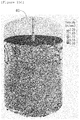
- FIGS. 14A and 14B are a photographic image and a graph illustrating the nickel-cobalt-manganese precursor (Ni x Co y Mn 1-x-y (OH) 2 ) having a concentration gradient depending on a center distance to enhance high capacity and thermal safety of the cathode active material. This indicates that a concentration of nickel (Ni) is high in the center while those of cobalt (Co) and manganese (Mn) are relatively increasing in a direction away from the center.
- a co-precipitation reaction is carried out by injecting a pre-determined amount of ammonia (NH 4 OH; second solution) and a target pH is adjusted with sodium hydroxide (NaOH; first solution), followed by adding a metal solution (having a composition of Ni:Co:Mn in the case of NCM or Ni:Co:Al in the case of NCA), NaOH (first solution) and NH4OH (second solution) .
- the raw material is limited to the metal solution and the first and second solutions (NaOH and NH 4 OH) to describe the exemplary embodiment; however, the raw material is not limited thereto.
- the reaction apparatus 1 may be provided to include a reaction vessel 10, a stirring means 30 inside the reaction vessel 10 and having multistage impellers 32, and a raw material-injecting means including at least one injection nozzle connected to the reaction vessel and injecting a raw material into at least an interspace A1 between the impellers.
- reaction apparatus 1 of the present disclosure basically involves injecting the previously described metal solution and first and second solutions into the interspace A1 between the impellers 32.
- a reaction effect may be increased when the solutions are injected into the interspace A1 between the impellers.
- the reaction vessel 10 of the reaction apparatus 1 is schematically illustrated in the drawings, but may be provided in a structure in which a cylindrical body (no reference number) of the center, a bottom 12 and an upper cover (no reference number) are assembled via a flange structure, or a structure in which the upper cover is easily detached from or assembled with the cylindrical body as the stirring means 30 is disposed therein.
- the stirring means 30 of the reaction apparatus 1 may include multistage impellers 32, preferably at least four-staged impellers 32.
- impellers are connected to a rotating shaft 40, which is connected to a motor 34, a coupling 36 and a sealing member 38 provided in an external upper side of the reaction vessel 10, and penetrates the reaction vessel 10 vertically, and whose lower portion is supported by a bearing 42.
- Impellers 32 are provided in at least four stages in the vertical direction of the rotating shaft, and four impellers 32 in each stage are provided in a circumferential direction on the rotation shaft 40.
- the impellers 32 may not be provided horizontally with the rotating shaft 40 but may be provided to be inclined for a stirring effect.
- the raw material-injecting means in the reaction apparatus 1 basically includes a first raw material-injecting means 50 injecting a metal solution into at least an interspace A1 between the impellers.
- the first raw material-injecting means 50 is disposed outside of the reaction vessel 10 and is connected to a metal solution-mixing means 90 mixing a shell solution and a core solution of the meal solution at a pre-determined ratio and supplying the same.
- reaction apparatus 1 of the present disclosure employs mixing the shell solution and the core solution of the metal solution at a pre-determined ratio and supply the same to the first raw material-injecting means 50, a cathode active material precursor (Ni x Co y Mn 1-x-y (OH) 2 or Ni x CO y Aln 1-x-y (OH) 2 ) having a concentration gradient according to a center distance can be easily produced and co-precipitation efficiency can be improved.
- a cathode active material precursor Ni x Co y Mn 1-x-y (OH) 2 or Ni x CO y Aln 1-x-y (OH) 2
- a core solution and a shell solution were conventionally supplied to a reaction vessel (10) depending on manual experience, which caused a lot-by-lot variation.
- the mixing means 90 includes a mixing tank 92, to which a core solution-supply pipe 94 and a shell solution-supply pipe 96 are separately connected, and flow regulators L are provided in the core solution-supply pipe 94 and the shell solution-supply pipe 96 to regulate a supply amount of each solution.
- the mixing tank 92 of the mixing means 90 is connected to a connection pipe 98 and the metal solution-supply pipe 100 of the first raw material-inj ecting means 50 injecting the metal solution into the reaction vessel.
- the previously described flow regulator L is also provided in the connection pipe 98.
- the core and shell solutions are supplied to the mixing tank 92 at a pre-determined flow rate through the flow regulator L.
- the core and shell solutions are mixed in the mixing tank, and the metal solution in which the core and shell solutions are mixed at a pre-determined ratio is supplied to injection nozzles of the first raw material-injecting means 50 through the connection pipe 98.
- the metal solution can also be controlled to be supplied to the first raw material-inj ecting means 50 at a pre-determined flow rate by the flow regulator L provided in the connection pipe 98.
- the raw material may further include first and second solutions for preparation of a cathode active material precursor for a lithium secondary battery.
- the raw material-injecting means of the present disclosure may further include second and third raw material-injecting means 60 and 70 for injecting the first and second solutions into at least the interspace A1 between the impellers, in addition to the first raw material-injecting means 50 injecting the metal solution into the reaction vessel 10.
- the first to third raw material-injecting means 50 to 70 of the reaction apparatus 1 may include injection nozzles 52, 54, 56, 62, 64, 66, 72, 74 and 76 injecting the raw materials (the metal solution, the first and second solutions) into an interspace A2 between a bottom 12 of the reaction vessel 10 and a lowermost impeller, in addition to the interspace A1 between the impellers described above.
- the first to third raw material-injecting means 50 to 70 can include three-staged injection nozzles 52, 54, 56, 62, 64, 66, 72, 74 and 76.
- An injection nozzle for injecting the solutions into an interspace between the first stage impellers and the second stage impellers can also be included.
- the first raw material-injecting means 50 injecting the metal solution into the reaction vessel may preferably be spaced apart from the second and third raw material-injecting means 60 and 70 respectively injecting the first and second solutions into the reaction vessel by 90° from left to right counterclockwise in a cross-section of the reaction vessel.
- the injection nozzles 52, 54 and 56 of the first raw material-inj ecting means 50 may be individually connected to three metal solution-supply pipes 100 connected to the connection pipe 98, which is connected to the mixing means 90.
- the three metal solution-supply pipes 100 while being spaced apart from each other, may be installed to be perpendicular to supporters 102 installed through an upper cover (no reference number) of the reaction vessel 10 as illustrated in FIG. 3 .
- the injection nozzles 62, 64, 66, 72, 74 and 76 of the second and third raw material-injecting means 60 and 70, which inject the first and second solutions may be provided in a lower portion of the three solution-supply pipes 110 vertically fixed to supporters 112 installed through the reaction vessel 10.
- the three metal solutions and solution-supply pipes 100 and 111 are connected to distributors 104 and 106, and opening/closing valves V may be provided in the supply pipes to control the supply. Accordingly, the metal solutions and the solutions may be injected to the spaces A1 and A2 inside the reaction vessel through the entire nozzles or selectively through the injection nozzles.
- the metal solution-connection pipes 98 connected to the mixing tank 92 and connection pipes 99 connected to first and second solution tanks may be connected to the distributors 104 and 106. Supply flow rates of the first and second solutions can also be controlled by the flow regulators (not illustrated).
- a vessel weight-sensing means 130 is further provided outside of the reaction vessel 10 .
- the vessel weight-sensing means 134 such as a load cell, and the like, may be provided in a lower portion of one of supporting structures 132 attached to the outside of the reaction vessel 10.
- FIG. 1 Although a single vessel weight-sensing means 130 is illustrated in FIG. 1 , it may be provided at least on both sides of the reaction vessel.
- injection positions inside the reaction vessel through the injection nozzles 52, 54, 56, 62, 64, 66, 72, 74 and 76 of the first to third raw material-injecting means 50, 60 and 70 can be adjusted since the reaction vessel 10 of the present disclosure has an increasing weight as levels of the solutions injected thereinside increase.
- the metal solution and the first and second solutions are injected together with water through the lowermost injection nozzles 56, 66 and 76 located in the interspace A2 between the lowermost impeller 32 and the vessel bottom 12 during an initial stage of operation.
- the solutions and water may be injected inside the reaction vessel sequentially through the injection nozzles 52, 54, 62, 64, 72 and 74 disposed in the interspace A1 between the third stage impellers and the fourth stage impellers and the interspace A2 between the second stage impellers and the third stage impellers.
- the metal solutions and the first and second solutions are injected into the interspace between impellers inside the reaction vessel through the first to third raw material-injecting means 50, 60 and 70, and the injection can be carried out sequentially depending on the locations of the injection nozzles corresponding to the solution levels in the reaction vessels.
- the injection method of the present disclosure involving injecting the metal solution and the first and second solutions into at least the interspaces between the impellers to correspond to the solution levels of the reaction vessel through the multistage injection nozzles may maximize efficiency in reduction of concentration difference.
- FIGS. 15A to 15C illustrate a simulation result obtained by comparing flows and a difference in concentrations according to the solution levels in the reaction vessel.
- a level of the injected solution is low, there is no significant different in concentration, whereas the concentration difference between a lower portion and an upper portion of the solution increases as the injected solution level increases.
- morphology of a cathode active material precursor in a growth stage is determined by pH.
- pH As illustrated in FIG. 15 , in a conventional case, in which the injection nozzle is present only in the lower portion of the reaction vessel, difference in pH between the upper and lower portion increases as the solution level increases, since the solutions are injected only in the lower portion of the vessel despite the increased solution level.
- concentrations of the metal solution and NH 4 OH (second solution) may not be uniform.
- a chelating agent for production of a complex ion may be injected to stimulate co-precipitation.
- Changes in the concentration of such a complex ion chelating agent affect nucleus and core creation during an initial stage of the co-precipitation and growth rate during precursor growth.
- the precursor cannot easily have uniform morphology, thereby causing poor sphericity and a slow growth rate.
- the nucleus may be generated, which gives rise to generation of fine powder.
- the metal solutions and the first and second solutions are injected into the interspaces between the impellers through at least three-staged injection nozzles disposed in a vertical direction of the reaction vessel according to the solution level.
- FIGS. 16A and 16B show results of simulation with difference in concentrations of the metal solution and the first and second solutions (NaOH and NH 4 OH) depending on the injection positions of the injection nozzles in a radial direction of the impellers 32
- FIG. 17 shows a graph of flow rates depending on the positions in the impeller 32.
- the flow rate according to positions in the radial direction of the impeller is highest at the center of the impeller, that is, a position spaced apart from a rotational axis 40 at a certain distance in the radial direction of the impeller. Accordingly, it is preferable that the injection nozzles be disposed in a position where the flow rate is the highest to inject the solutions.
- the injection nozzles of the present disclosure it is most preferable to arrange the injection nozzles of the present disclosure at a position spaced about 0.4 m from the rotational axis in the impeller radial direction, and to inject the solutions. That is, it may be desirable to position the injection nozzle near the center in the radial direction of the entire length of the impeller.
- the solutions are injected into at least the interspace ("B" region of FIG. 16A ) between the impellers, the solutions are injected in a space (region) where the flow rate is relatively high in the radial direction of the impeller.
- the metal solution and the first and second solutions are injected at a position spaced apart from the rotational axis in the radial direction of the impeller in the interspace A1 between the impellers, not a region adjacent to the reaction vessel wall, at a pre-determined distance through the injection nozzles.
- manufacture quality of the Ni-Co-Mn precursor (Ni x Co y Mn 1-x-y (OH) 2 ) or Ni-Co-Al precursor (Ni x Co y Aln 1-x-y (OH) 2 ) having a concentration gradient according the center distance can be particularly enhanced.
- FIG. 18 illustrates particle size growth according to a reaction time of the Ni-Co-Mn precursor (Ni x Co y Mn 1-x-y (OH) 2 ) prepared through the reaction apparatus 1 of the present disclosure.
- a case (red) in which the position of the solution injection of the injection nozzle is adjusted according to the solution level as in the present disclosure has a greater particle size growth rate than a conventional case (blue), in which the solution is only injected into the lower portion of the reaction vessel while fixing the injection position of the injection nozzle along the vessel wall.
- the present disclosure has a relatively higher growth rate of precursor particles compared to conventional cases.
- pores were not generated in the precursor and the concentration gradient is well formed.
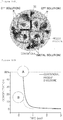
- FIGS. 19A and 19B are a photographic image illustrating the Ni-Co-Mn precursor (Ni x Co y Mn 1-x-y (OH) 2 ) having the concentration gradient according the center distance and a graph of the concentration gradient.
- FIG. 20 is a table showing comparison of particle sizes and tap density of the Ni-Co-Mn precursor (Ni x Co y Mn 1-x-y (OH) 2 ) having a particle size of as small as 5 ⁇ m, which is prepared by the reaction apparatus and the method according to the present disclosure.
- the reaction time and tap density of the present disclosure in which the injection position of the injection nozzle varies according to the solution level is enhanced compared to a conventional case, in which the injection position of the injection nozzle is fixed to the lower portion of the reaction vessel.
- the reaction apparatus 1 of the present disclosure has an improved growth rate of precursor under the same process condition by suppressing the generation of a difference in concentrations in the reaction vessel 10.
- the sphericity of the precursor may be improved and due to uniform stirring, generation of particles having a particle size larger than a target particle size can be suppressed.
- the morphology of a primary particle of a precursor varies generally depending on pH thereof.
- a Ni content in the Ni x Co y Mn 1-x-y (OH) 2 precursor is greater than 80%, the primary particle has a needle shape at a pH of 11 and a flake shape at a pH of 12.
- NaOH is generally added.
- a relatively high pH is maintained near the nozzle, while a low pH is maintained at a distance away from the nozzle due to co-precipitation consuming OH-. This leads to reduction of uniformity of the morphology during precursor growth, and becomes worse as the capacity of the co-precipitation reactor increases.
- reaction apparatus 1 of the present disclosure is advantageous in terms of morphology as the concentration difference in the reaction vessel can be overcome.
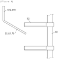
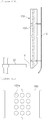
- FIGS. 4 to 9 illustrate exemplary embodiments of the injection nozzles of the reaction apparatus 1 of the present disclosure (only the reference numbers of 52, 62 and 72 are indicated for the injection nozzles in the drawings; however, other injection nozzles 54, 56, 64, 66, 74 and 76 are applicable).
- the injection nozzles 52, 62 and 72 of the first to third raw material-injecting means 50, 60 and 70 may be provided in an interspace N1 between the reaction vessel bottom 12 and the impellers and an interspace N2 between the impellers in the form bent at least 90° in lower portions of the supply pipes 100 and 110, as previously described.
- the injection nozzles of the present disclosure are provided in a structure bent at least 90°, there is no remainder of the solutions inside the nozzle. Further, as the injection nozzles are in the form of a nozzle, which is bent and extends from the lower portion of the vertical supply pipes 100 and 110 inside the reaction vessel 10, a collision occurs with the nozzle itself when the solution is stirred, thereby increasing the stirring efficiency.
- an additional projection (bent) portions X at an end of the nozzle may improve the stirring efficiency upon stirring with the solution.
- the injection nozzles 52, 62 and 72 may be integrally bent at the lower portion of the metal solution-supply pipe 100 and the first and second solution-supply pipe 110 to provide a nozzle portion or assembled with the supply pipes by a screw S fastening method in a disassembled state.
- the injection nozzles to be assembled in FIG. 6 may require an additional assembling process but may be advantageous in modifying or maintaining the form of the injection nozzles.
- the injection nozzles of the present disclosure may be provided as a coil-type injection nozzle C.
- the coil-type injection nozzle C may maximize a collision effect with the solution during stirring, thereby improving the stirring effect.
- the injection nozzles of the present disclosure in a plane may be disposed to be inclined at an angle in a direction of rotation of the impellers 32, which is a stirring means 30.
- the solutions are injected in an inclined angle in the direction of rotation of the impellers, thereby enhancing the stirring effect.
- the injection nozzles may be provided to have a plurality of raw material-injecting holes H with an appropriate gradient.
- the solutions are further dispersed in at least the interspace between the impellers and the interspace between the impellers and the vessel bottom, thereby enhancing the stirring effect or reaction effect.
- the metal solution and first and second solution-supply pipes having the injection nozzles 52, 62 and 72 provided in the lower portions thereof may be provided as a movable supply pipe 120 capable of moving vertically through the reaction vessel 10.
- a supply pipe 122 having a long rack 124 on one side thereof is provided inside a guide 126 installed in an opening of an upper cover (no reference number) of the reaction vessel 10, and a drive pinion 129 driven as a motor 128 provided on the upper cover at the outside of the reaction vessel 10 engages with the rack 124 of the movable supply pipe.
- the supply pipe 122 supported via the guide 126 according to a driving direction of the motor may be provided to be vertically movable through the reaction vessel 10.
- the supply pipe 122 be beyond the rotational radius of the impeller, while the bent injection nozzles 52, 62 and 72 in the lower end thereof be provided to allow the metal solution and the first and second solutions to be blown into at least the interspace N2 between the impellers and the interspace N2 between the impellers and the reaction vessel bottom 12.
- Such movable supply pipe 120 is disposed at an interval of 90° in the counterclockwise direction of the reaction vessel to allow the metal solution and the first and second solutions to be injected inside the reaction vessel; however, the supply pipe 122 may be connected to a flexible pipe 127 compensating vertical movements of the supply pipe, not of the connection pipe of FIG. 3 , which supplies the metal solution and the first and second solutions.
- the movable supply pipe 120 of the present disclosure vertically moves according to the solution level in the reaction vessel while appropriately injecting the metal solution and the first and second solutions into a desired space (N1 or N2).
- the reaction apparatus 1 may further include at least one porous baffle 150 provided inside the reaction vessel 10.
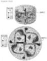
- FIGS. 21A and 21B show simulation results of flows according to presence of the baffles. Compared to FIG. 21A , in which no baffles are present, FIG. 21B , in which baffles are present, showed more active flow.
- FIGS. 22A and 22B show simulation results of flows of baffles 150' having no holes and the porous baffles 150 of the present disclosure. In the case of the porous baffle 150 in which holes 152 are formed, improved flow was observed.
- porous baffles 150 of the present disclosure may be provided at an interval of 90° through a support 151 on an inner wall of the reaction vessel 10.
- porous baffles 150 contrary to existing baffles, have holes 152 formed therein.
- fluidity of the injected solutions is further improved during the operation of the reaction apparatus, thereby enhancing the reaction effect.
- FIGS. 11 to 13 illustrate various exemplary embodiments of such porous baffles 150 of the present disclosure.
- a plurality of the holes 152 provided in the porous baffle 150 may preferably be formed in various shapes such as a circular shape 152a, an elliptical shape 152b, a square shape 152c, a rectangular shape 152d and f, and the like.
- an insertion fixer 156 may further be included to be inserted in at least one opening 154 provided in the porous baffle 150 and to have the holes 152 formed therein.
- the holes 152 in a desired form are formed in a plurality of the insertion fixers 156 and can appropriately be utilized according to an operational environment of the reaction apparatus.
- the holes 152 of the porous baffle 150 may be provided as inclined holes 152' whose outlet 152'b is narrower than an inlet 152'a in a cross-section thereof.
- Such inclined holes 152' may be provided in a baffle opening 154 through an additional insertion fixer 156, and the inclined holes involves a solution collision and discharge, thereby increasing the fluidity. This will enhance the reaction effect.
- the porous baffle 150 of the present disclosure be provided in a structure extending only to at least a periphery of a horizontal line Y of the lowermost impeller 32 of the stirring means 30.
- FIGS. 23A and 23B are images of simulation illustrating a flow state when the baffle extends only to at least a periphery of the horizontal line Y of the lowermost impeller 32 as in the present disclosure, and a case where the baffle extends beyond the lowermost impeller to the bottom of the reaction vessel.
- FIG. 23A there is less ununiform flow, and in FIG. 23B , a dead zone is generated.
- the case of the reaction apparatus 1 of the present disclosure may further be provided with a nozzle 190 for nitrogen purging, a Di-water nozzle 210, and the like, for internal purging of the reaction vessel.
- a heater 230 may further be provided on an outer edge of the reaction vessel 10 for temperature control of the solution in the vessel.
- a sensing tank 170 for discharging the solution from the lower portion of the reactor using a circulating pump to circulate may further be provided on one side of an upper portion of the reaction vessel 10.
- reaction method of the present disclosure based on thus-far described reaction apparatus 1 employs metal solution injection involving injecting a metal solution obtained by mixing a core solution and a shell solution at a pre-determined ratio into a reaction vessel at a pre-determined flow rate, solution injection involving injecting other solutions into the reaction vessel at a pre-determined flow rate, and co-precipitation involving stirring the other solutions with the metal solution injected into the reaction vessel to prepare a cathode active material for a lithium secondary battery having a concentration gradient.
- the metal solution and the other solutions in the reaction method are injected into at least the interspace A2 between the lowermost impeller and the reaction vessel bottom 12 in addition to the interspace A1 between the impellers of the stirring means.
- the metal solutions and the other solutions are injected into the reaction vessel corresponding to a level of the solutions in the reaction vessel, which is detected by the vessel weight-sensing means 130.
- the metal solution having a composition of Ni:Co:Mn or Ni:Co:Al and the other solutions of NaOH and NH 4 OH are reacted to prepare a nickel-cobalt-manganese precursor (Ni x Co y Mn 1-x-y (OH) 2 ) or a nickel-cobalt-aluminum precursor (Ni x Co y Aln 1-x-y (OH) 2 ) having a concentration gradient according to at least a center distance.
- the present disclosure is useful in preparation of a catalyst or a cathode active material for a lithium secondary battery.
Landscapes
- Chemical & Material Sciences (AREA)
- Chemical Kinetics & Catalysis (AREA)
- Organic Chemistry (AREA)
- Inorganic Chemistry (AREA)
- Engineering & Computer Science (AREA)
- Electrochemistry (AREA)
- General Chemical & Material Sciences (AREA)
- Materials Engineering (AREA)
- Manufacturing & Machinery (AREA)
- Aviation & Aerospace Engineering (AREA)
- Battery Electrode And Active Subsutance (AREA)
- Inorganic Compounds Of Heavy Metals (AREA)
- Physical Or Chemical Processes And Apparatus (AREA)
- Mixers Of The Rotary Stirring Type (AREA)
Abstract
Description
- The present disclosure relates to a reaction apparatus and a method, and more particularly to in a co-precipitation reaction for preparation of a catalyst or a cathode active material for a lithium secondary battery, a raw material (solution) is introduced into at least an interspace between impellers corresponding to a solution level in a vessel, thereby making a stirring speed uniform and particularly to minimizing a difference in concentrations between solutions.
- Recently, as demand for mobile devices such as smart phones and laptops has increased and the hybrid or electric vehicle market has grown, demand for secondary batteries as an energy source is rapidly increasing. Among such secondary batteries, lithium secondary batteries exhibiting high energy density and operating potential and having a long cycle life and a low self-discharge rate are being widely used.
- Lithium-containing cobalt oxides (LiCoO2) are mainly used as a cathode active material of such lithium secondary batteries. In addition, use of lithium-containing manganese oxides such as LiMnO2 having a layered crystal structure and LiMn2O4 having a spinel crystal structure, and lithium-containing nickel oxides (LiNiO2) and ternary LiNixMnyCO(1-x-y)O2 is also being researched.
- Generally, the cathode active material of lithium secondary batteries is manufactured by a solid sate reaction at a high temperature of at least 700°C. This case, however, accompanies physical mixing and pulverization, thereby making a mixed state not uniform, and thus requires mixing and pulverization several times. Consequently, it takes an increased amount of manufacturing time and manufacturing costs also increase.
- In this regard, wet manufacturing methods, represented by a sol-gel method and a co-precipitation method, which include hydrolysis and condensation, have been developed.
- Meanwhile, in manufacturing of a nickel-cobalt-manganese precursor (NixCoyMn1-x-y(OH)2) or a nickel-cobalt-aluminum precursor (NixCoyAln1-x-y(OH)2), which is used as a cathode active material after being mixed with lithium in the lithium secondary batteries and sintered, co-precipitation methods employing a continuous stirred tank reactor (CSTR), Couette Taylor reactor, batch reactor, or the like, are widely utilized.
- Such co-precipitation methods include precipitating chlorides, nitrides, or sulfides containing raw materials in a basic solution into hydroxides and enlarging a particle size thereof. In this regard, shapes, particle sizes, and morphology of the cathode active material precursor change depending on a pH, a temperature, and stirring conditions of a solution.
- When a cathode active material precursor of a lithium secondary battery is manufactured by existing co-precipitation methods, CSTRs capable of mass production are mainly used. In the case of the CSTRs, however, a stirring speed of internal impellers may not be uniform while delaying a reaction time and increasing stabilization costs until a certain quality is achieved, thereby making it difficult to secure productivity and economic feasibility when a reaction is scaled up.
- Meanwhile, to resolve the known problems of the CSTRs, a reactor using a Taylor vortex is used in terms of ununiform stirring speeds; however, due to high costs for stabilization, the reactor is applied only to particles having a small particle size of 7 µm or less. In the case of a scaled-up reaction, the reactor has an increasing diameter, thereby disabling formation of uniform Taylor vortex.
- Furthermore, technology related to the manufacture of a precursor having a concentration gradient according to a center distance for improved high capacity characteristics and thermal safety of a cathode active material for lithium secondary batteries is disclosed in Korean Patent Laid-Open Publication No.
2005-0083869 - In order to resolve such conventional problems, an aspect of the present disclosure is to provide an apparatus involving injecting raw materials (solutions) into at least an interspace between impellers according to a solution level in a vessel during co-precipitation for preparation of a catalyst or a cathode active material for a lithium secondary battery to have a uniform stirring speed and particularly to minimize a difference in concentrations between the solutions, and a method therefor.
- According to an aspect, the present disclosure includes a reaction vessel, a stirring means provided inside the reaction vessel and having multistage impellers, and a raw material-injecting means connected to the reaction vessel and including at least one injection nozzle injecting a raw material into an interspace between impellers.
- According to another aspect of the present disclosure, the present disclosure includes metal solution injection involving injecting a metal solution obtained by mixing a core solution and a shell solution at a pre-determined ratio into a reaction vessel at a pre-determined flow rate, solution injection involving injecting other solutions into the reaction vessel at a pre-determined flow rate, and co-precipitation involving stirring the other solutions with the metal solution injected into the reaction vessel to prepare a cathode active material for a lithium secondary battery.
- According to the present disclosure, an effect of significantly reducing or suppressing a difference in concentrations of raw materials (solutions) in a reaction vessel is provided.
- In particular, the present disclosure provides other effects of improving a growth rate of a cathode active material for a lithium secondary battery under same process conditions by performing uniform stirring and removing a concentration gradient while also improving sphericity of the precursor.
-
-
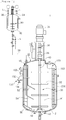
FIG. 1 is an overall configuration diagram illustrating a (co-precipitation) reaction apparatus according to the present disclosure. -
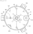
FIG. 2 is a schematic planar view ofFIG. 1 . -
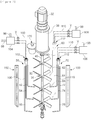
FIG. 3 is a partially exploded perspective view schematically illustrating the reaction apparatus ofFIG. 1 . -
FIG. 4 is a pictorial schematic diagram illustrating an injection nozzle of a raw material-injecting means of the present disclosure. -
FIGS. 5A to 5C are schematic diagrams illustrating other exemplary embodiments of the injection nozzle ofFIG. 4 . -
FIG. 6 is a perspective view of another exemplary embodiment of the injection nozzle. -
FIG. 7 is a perspective view of another exemplary embodiment of the injection nozzle. -
FIG. 8 is a schematic planar view of an installation environment of the injection nozzle. -
FIG. 9 is a perspective view of another exemplary embodiment of the injection nozzle. -
FIG. 10 is a diagram illustrating a mobile configuration of a supply pipe connected to the injection nozzle. -
FIGS. 11A and11B to 11F are an enlarged view of and schematic diagrams illustrating a porous baffle of the present disclosure. -
FIG. 12 is a perspective view of another exemplary embodiment of the porous baffle. -
FIG. 13 is a sectional view of another exemplary embodiment of the porous baffle. -
FIGS. 14A and 14B are a photographic image and a graph illustrating a cathode active material (nickel-cobalt-manganese precursor (NixCoyMn1-x-y(OH)2)) having a concentration gradient depending on a center distance. -
FIGS. 15A to 15C are images of simulation comparing flow and concentration gradient difference according to a solution level in a vessel. -
FIGS. 16A and 16B are a image of simulation and a graph illustrating a difference in concentrations caused by different positions of the injection nozzle of the present disclosure and the prior art. -
FIG. 17 is a graph illustrating flow rates of impellers according to positions thereof. -
FIG. 18 is a graph illustrating particle size growth according to a reaction time of the nickel-cobalt-manganese precursor (NixCoyMn1-x-y(OH)2) of the present disclosure and the prior art. -
FIGS. 19A and 19B are photographic images illustrating the nickel-cobalt-manganese precursor (NixCoyMn1-x-y(OH)2) having the concentration gradient according to the present disclosure and a graph of concentration gradients. -
FIG. 20 is a comparative table showing a particle size and tap density of the nickel-cobalt-manganese precursor (NixCoyMn1-x-y(OH)2). -
FIGS. 21A and21B are images of simulation illustrating a flow state according to a presence of the baffle. -
FIGS. 22A and22B are images of simulation illustrating a flow state according to a presence of pores of the baffle. -
FIGS. 23A and23B are images of simulation illustrating a flow state according to an extended structure of a lower portion of the baffle. - Hereinafter, the present disclosure will be described in detail with reference to the accompanying drawings. Throughout the drawings and the detailed description, unless otherwise described, the same drawing reference numerals are understood to refer to the same elements, features, and structures. In describing the exemplary embodiments, detailed description on known configurations or functions may be omitted for clarity and conciseness.
- A
reaction apparatus 1 of the present disclosure is may be a co-precipitation apparatus preparing a catalyst or a cathode active material for a lithium secondary battery based on a continuous stirring reactor (CSTR). - The reaction apparatus is not necessarily limited to be utilized in a production environment of cathode active materials, and may be applied to, for example, reactions (production) of other materials involving injecting a raw material (solution) and stirring based on a stirring means to react.
- In addition, as a preferred embodiment, the present disclosure may relate to a co-precipitation reaction for production of a cathode active material precursor for a lithium secondary battery, for example, a nickel-cobalt-manganese precursor (NixCoyMn1-x-y(OH)2) or a nickel-cobalt-aluminum precursor (NixCoyAln1-x-y(OH)2) having a concentration gradient depending on a center distance.
- For example,
FIGS. 14A and 14B are a photographic image and a graph illustrating the nickel-cobalt-manganese precursor (NixCoyMn1-x-y(OH)2) having a concentration gradient depending on a center distance to enhance high capacity and thermal safety of the cathode active material. This indicates that a concentration of nickel (Ni) is high in the center while those of cobalt (Co) and manganese (Mn) are relatively increasing in a direction away from the center. - Further, in an exemplary embodiment, a co-precipitation reaction is carried out by injecting a pre-determined amount of ammonia (NH4OH; second solution) and a target pH is adjusted with sodium hydroxide (NaOH; first solution), followed by adding a metal solution (having a composition of Ni:Co:Mn in the case of NCM or Ni:Co:Al in the case of NCA), NaOH (first solution) and NH4OH (second solution) . In this regard, the raw material is limited to the metal solution and the first and second solutions (NaOH and NH4OH) to describe the exemplary embodiment; however, the raw material is not limited thereto.
- Hereinbelow, the present disclosure will be described in detail.
- As illustrated in
FIGS. 1 to 3 , thereaction apparatus 1 according to the present disclosure may be provided to include areaction vessel 10, a stirring means 30 inside thereaction vessel 10 and havingmultistage impellers 32, and a raw material-injecting means including at least one injection nozzle connected to the reaction vessel and injecting a raw material into at least an interspace A1 between the impellers. - In other words, the
reaction apparatus 1 of the present disclosure basically involves injecting the previously described metal solution and first and second solutions into the interspace A1 between theimpellers 32. A reaction effect may be increased when the solutions are injected into the interspace A1 between the impellers. - The
reaction vessel 10 of thereaction apparatus 1 is schematically illustrated in the drawings, but may be provided in a structure in which a cylindrical body (no reference number) of the center, a bottom 12 and an upper cover (no reference number) are assembled via a flange structure, or a structure in which the upper cover is easily detached from or assembled with the cylindrical body as the stirring means 30 is disposed therein. - As illustrated in
FIGS. 1 and3 , the stirring means 30 of thereaction apparatus 1 may includemultistage impellers 32, preferably at least four-stagedimpellers 32. - In other words, the impellers are connected to a
rotating shaft 40, which is connected to amotor 34, acoupling 36 and a sealingmember 38 provided in an external upper side of thereaction vessel 10, and penetrates thereaction vessel 10 vertically, and whose lower portion is supported by abearing 42.Impellers 32 are provided in at least four stages in the vertical direction of the rotating shaft, and fourimpellers 32 in each stage are provided in a circumferential direction on therotation shaft 40. - The
impellers 32 may not be provided horizontally with the rotatingshaft 40 but may be provided to be inclined for a stirring effect. - As further illustrated in
FIGS. 1 to 3 , the raw material-injecting means in thereaction apparatus 1 basically includes a first raw material-injecting means 50 injecting a metal solution into at least an interspace A1 between the impellers. - In particular, the first raw material-injecting means 50 is disposed outside of the
reaction vessel 10 and is connected to a metal solution-mixing means 90 mixing a shell solution and a core solution of the meal solution at a pre-determined ratio and supplying the same. - In this regard, as the
reaction apparatus 1 of the present disclosure employs mixing the shell solution and the core solution of the metal solution at a pre-determined ratio and supply the same to the first raw material-injecting means 50, a cathode active material precursor (NixCoyMn1-x-y(OH)2 or NixCOyAln1-x-y(OH)2) having a concentration gradient according to a center distance can be easily produced and co-precipitation efficiency can be improved. - For example, although not illustrated in the drawings, a core solution and a shell solution were conventionally supplied to a reaction vessel (10) depending on manual experience, which caused a lot-by-lot variation.
- As illustrated in
FIG. 1 , the mixing means 90 includes amixing tank 92, to which a core solution-supply pipe 94 and a shell solution-supply pipe 96 are separately connected, and flow regulators L are provided in the core solution-supply pipe 94 and the shell solution-supply pipe 96 to regulate a supply amount of each solution. - The mixing
tank 92 of the mixing means 90 is connected to aconnection pipe 98 and the metal solution-supply pipe 100 of the first raw material-inj ecting means 50 injecting the metal solution into the reaction vessel. The previously described flow regulator L is also provided in theconnection pipe 98. - As illustrated in
FIG. 1 , in the case where the metal solution is injected inside thereaction vessel 10, particularly at least an interspace A1 between theimpellers 32, the core and shell solutions are supplied to themixing tank 92 at a pre-determined flow rate through the flow regulator L. The core and shell solutions are mixed in the mixing tank, and the metal solution in which the core and shell solutions are mixed at a pre-determined ratio is supplied to injection nozzles of the first raw material-injecting means 50 through theconnection pipe 98. - The metal solution can also be controlled to be supplied to the first raw material-inj ecting means 50 at a pre-determined flow rate by the flow regulator L provided in the
connection pipe 98. - As previously described and illustrated in
FIGS. 1 to 3 , the raw material may further include first and second solutions for preparation of a cathode active material precursor for a lithium secondary battery. Accordingly, the raw material-injecting means of the present disclosure may further include second and third raw material-injecting means 60 and 70 for injecting the first and second solutions into at least the interspace A1 between the impellers, in addition to the first raw material-injecting means 50 injecting the metal solution into thereaction vessel 10. - More preferably, the first to third raw material-injecting means 50 to 70 of the
reaction apparatus 1 may includeinjection nozzles reaction vessel 10 and a lowermost impeller, in addition to the interspace A1 between the impellers described above. - That is, when an upper side of the four-staged impellers refers to a first stage, in order to inject first and second raw materials together with the metal solution into an interspace between second stage impellers and third stage impellers, an interspace between the third stage impellers and fourth stage impellers and the interspace A2 between the fourth stage impellers and the vessel bottom, the first to third raw material-injecting means 50 to 70 can include three-staged
injection nozzles - An injection nozzle for injecting the solutions into an interspace between the first stage impellers and the second stage impellers can also be included.
- Further, as illustrated in
FIG. 2 , the first raw material-injecting means 50 injecting the metal solution into the reaction vessel may preferably be spaced apart from the second and third raw material-injecting means 60 and 70 respectively injecting the first and second solutions into the reaction vessel by 90° from left to right counterclockwise in a cross-section of the reaction vessel. - More specifically, the
injection nozzles supply pipes 100 connected to theconnection pipe 98, which is connected to the mixing means 90. - The three metal solution-
supply pipes 100, while being spaced apart from each other, may be installed to be perpendicular tosupporters 102 installed through an upper cover (no reference number) of thereaction vessel 10 as illustrated inFIG. 3 . - Similarly, the
injection nozzles supply pipes 110 vertically fixed tosupporters 112 installed through thereaction vessel 10. - In order to enable the solutions to be selectively injected through the injection nozzles, the three metal solutions and solution-
supply pipes 100 and 111, as illustrated inFIG. 3 , are connected todistributors - The metal solution-
connection pipes 98 connected to themixing tank 92 andconnection pipes 99 connected to first and second solution tanks (not specifically illustrated) may be connected to thedistributors - More preferably, a vessel weight-sensing means 130 is further provided outside of the
reaction vessel 10 . For example, as illustrated inFIG. 1 , the vessel weight-sensing means 134, such as a load cell, and the like, may be provided in a lower portion of one of supportingstructures 132 attached to the outside of thereaction vessel 10. - Although a single vessel weight-sensing means 130 is illustrated in
FIG. 1 , it may be provided at least on both sides of the reaction vessel. - Accordingly, injection positions inside the reaction vessel through the
injection nozzles reaction vessel 10 of the present disclosure has an increasing weight as levels of the solutions injected thereinside increase. - That is, as illustrated in
FIGS. 1 to 3 , the metal solution and the first and second solutions are injected together with water through thelowermost injection nozzles lowermost impeller 32 and the vessel bottom 12 during an initial stage of operation. As the solution level of the reaction vessel increases, the solutions and water may be injected inside the reaction vessel sequentially through theinjection nozzles - That is, in the
reaction apparatus 1, the metal solutions and the first and second solutions are injected into the interspace between impellers inside the reaction vessel through the first to third raw material-injecting means 50, 60 and 70, and the injection can be carried out sequentially depending on the locations of the injection nozzles corresponding to the solution levels in the reaction vessels. - The injection method of the present disclosure involving injecting the metal solution and the first and second solutions into at least the interspaces between the impellers to correspond to the solution levels of the reaction vessel through the multistage injection nozzles may maximize efficiency in reduction of concentration difference.
- Meanwhile,
FIGS. 15A to 15C illustrate a simulation result obtained by comparing flows and a difference in concentrations according to the solution levels in the reaction vessel. When a level of the injected solution is low, there is no significant different in concentration, whereas the concentration difference between a lower portion and an upper portion of the solution increases as the injected solution level increases. - Generally, morphology of a cathode active material precursor in a growth stage is determined by pH. As illustrated in
FIG. 15 , in a conventional case, in which the injection nozzle is present only in the lower portion of the reaction vessel, difference in pH between the upper and lower portion increases as the solution level increases, since the solutions are injected only in the lower portion of the vessel despite the increased solution level. The concentrations of the metal solution and NH4OH (second solution) may not be uniform. - In the case of the Ni-Co-Mn precursor (NixCoyMn1-x-y(OH)2), a chelating agent (NH4OH; second solution) for production of a complex ion may be injected to stimulate co-precipitation. Changes in the concentration of such a complex ion chelating agent affect nucleus and core creation during an initial stage of the co-precipitation and growth rate during precursor growth. When difference in the concentrations is generated, the precursor cannot easily have uniform morphology, thereby causing poor sphericity and a slow growth rate. During some intervals, the nucleus may be generated, which gives rise to generation of fine powder.
- Accordingly, in the case of the present disclosure, the metal solutions and the first and second solutions are injected into the interspaces between the impellers through at least three-staged injection nozzles disposed in a vertical direction of the reaction vessel according to the solution level. This enables suppression of concentration difference according to difference in solution levels and increases co-precipitation efficiency while improving cathode active material productivity.
-
FIGS. 16A and 16B show results of simulation with difference in concentrations of the metal solution and the first and second solutions (NaOH and NH4OH) depending on the injection positions of the injection nozzles in a radial direction of theimpellers 32, andFIG. 17 shows a graph of flow rates depending on the positions in theimpeller 32. - In
FIG. 16 , when the injection positions of the metal solution and the first and second solutions are "B" region, an interspace between the impellers of the present disclosure, rather than "A", a space adjacent to a wall of a conventional vessel container, the concentration difference in the injected solutions are small. - It can be seen in
FIG. 17 that the flow rate according to positions in the radial direction of the impeller is highest at the center of the impeller, that is, a position spaced apart from arotational axis 40 at a certain distance in the radial direction of the impeller. Accordingly, it is preferable that the injection nozzles be disposed in a position where the flow rate is the highest to inject the solutions. - For example, referring to
FIG. 17 , it is most preferable to arrange the injection nozzles of the present disclosure at a position spaced about 0.4 m from the rotational axis in the impeller radial direction, and to inject the solutions. That is, it may be desirable to position the injection nozzle near the center in the radial direction of the entire length of the impeller. - In the case of the present disclosure, as the solutions are injected into at least the interspace ("B" region of
FIG. 16A ) between the impellers, the solutions are injected in a space (region) where the flow rate is relatively high in the radial direction of the impeller. - Accordingly, in the present disclosure, the metal solution and the first and second solutions are injected at a position spaced apart from the rotational axis in the radial direction of the impeller in the interspace A1 between the impellers, not a region adjacent to the reaction vessel wall, at a pre-determined distance through the injection nozzles. In this regard, manufacture quality of the Ni-Co-Mn precursor (NixCoyMn1-x-y(OH)2) or Ni-Co-Al precursor (NixCoyAln1-x-y(OH)2) having a concentration gradient according the center distance can be particularly enhanced.
-
FIG. 18 illustrates particle size growth according to a reaction time of the Ni-Co-Mn precursor (NixCoyMn1-x-y(OH)2) prepared through thereaction apparatus 1 of the present disclosure. It can be understood that under the same process conditions, a case (red) in which the position of the solution injection of the injection nozzle is adjusted according to the solution level as in the present disclosure has a greater particle size growth rate than a conventional case (blue), in which the solution is only injected into the lower portion of the reaction vessel while fixing the injection position of the injection nozzle along the vessel wall. Further, the present disclosure has a relatively higher growth rate of precursor particles compared to conventional cases. As illustrated inFIG. 19 , however, pores were not generated in the precursor and the concentration gradient is well formed.FIGS. 19A and 19B are a photographic image illustrating the Ni-Co-Mn precursor (NixCoyMn1-x-y(OH)2) having the concentration gradient according the center distance and a graph of the concentration gradient. -
FIG. 20 is a table showing comparison of particle sizes and tap density of the Ni-Co-Mn precursor (NixCoyMn1-x-y(OH)2) having a particle size of as small as 5 µm, which is prepared by the reaction apparatus and the method according to the present disclosure. Under the same process conditions, the reaction time and tap density of the present disclosure, in which the injection position of the injection nozzle varies according to the solution level is enhanced compared to a conventional case, in which the injection position of the injection nozzle is fixed to the lower portion of the reaction vessel. - Consequently, the
reaction apparatus 1 of the present disclosure has an improved growth rate of precursor under the same process condition by suppressing the generation of a difference in concentrations in thereaction vessel 10. In addition, the sphericity of the precursor may be improved and due to uniform stirring, generation of particles having a particle size larger than a target particle size can be suppressed. - For example, the morphology of a primary particle of a precursor varies generally depending on pH thereof. When a Ni content in the NixCoyMn1-x-y(OH)2 precursor is greater than 80%, the primary particle has a needle shape at a pH of 11 and a flake shape at a pH of 12. To control pH, NaOH is generally added. When the flow is stagnant near an injection nozzle, a relatively high pH is maintained near the nozzle, while a low pH is maintained at a distance away from the nozzle due to co-precipitation consuming OH-. This leads to reduction of uniformity of the morphology during precursor growth, and becomes worse as the capacity of the co-precipitation reactor increases.
- That is, the
reaction apparatus 1 of the present disclosure is advantageous in terms of morphology as the concentration difference in the reaction vessel can be overcome. -
FIGS. 4 to 9 illustrate exemplary embodiments of the injection nozzles of thereaction apparatus 1 of the present disclosure (only the reference numbers of 52, 62 and 72 are indicated for the injection nozzles in the drawings; however,other injection nozzles - For example, as illustrated in
FIGS. 4 and5 , theinjection nozzles supply pipes - In other words, as the injection nozzles of the present disclosure are provided in a structure bent at least 90°, there is no remainder of the solutions inside the nozzle. Further, as the injection nozzles are in the form of a nozzle, which is bent and extends from the lower portion of the
vertical supply pipes reaction vessel 10, a collision occurs with the nozzle itself when the solution is stirred, thereby increasing the stirring efficiency. - For example, as shown in
FIGS. 5A and 5C , an additional projection (bent) portions X at an end of the nozzle may improve the stirring efficiency upon stirring with the solution. - As illustrated in
FIGS. 3 and6 , theinjection nozzles supply pipe 100 and the first and second solution-supply pipe 110 to provide a nozzle portion or assembled with the supply pipes by a screw S fastening method in a disassembled state. - The injection nozzles to be assembled in
FIG. 6 may require an additional assembling process but may be advantageous in modifying or maintaining the form of the injection nozzles. - As illustrated in
FIG. 7 , the injection nozzles of the present disclosure may be provided as a coil-type injection nozzle C. In this case, the coil-type injection nozzle C may maximize a collision effect with the solution during stirring, thereby improving the stirring effect. - As illustrated in
FIG. 8 , the injection nozzles of the present disclosure in a plane may be disposed to be inclined at an angle in a direction of rotation of theimpellers 32, which is a stirring means 30. In this case, the solutions are injected in an inclined angle in the direction of rotation of the impellers, thereby enhancing the stirring effect. - As illustrated in
FIG. 9 , the injection nozzles may be provided to have a plurality of raw material-injecting holes H with an appropriate gradient. In this case, the solutions are further dispersed in at least the interspace between the impellers and the interspace between the impellers and the vessel bottom, thereby enhancing the stirring effect or reaction effect. - As illustrated in
FIG. 10 , the metal solution and first and second solution-supply pipes having theinjection nozzles movable supply pipe 120 capable of moving vertically through thereaction vessel 10. - That is, as illustrated in
FIG. 10 , asupply pipe 122 having along rack 124 on one side thereof is provided inside a guide 126 installed in an opening of an upper cover (no reference number) of thereaction vessel 10, and adrive pinion 129 driven as amotor 128 provided on the upper cover at the outside of thereaction vessel 10 engages with therack 124 of the movable supply pipe. Accordingly, thesupply pipe 122 supported via the guide 126 according to a driving direction of the motor may be provided to be vertically movable through thereaction vessel 10. - It is preferable that the
supply pipe 122 be beyond the rotational radius of the impeller, while thebent injection nozzles reaction vessel bottom 12. - Such
movable supply pipe 120, as illustrated inFIG. 2 , is disposed at an interval of 90° in the counterclockwise direction of the reaction vessel to allow the metal solution and the first and second solutions to be injected inside the reaction vessel; however, thesupply pipe 122 may be connected to aflexible pipe 127 compensating vertical movements of the supply pipe, not of the connection pipe ofFIG. 3 , which supplies the metal solution and the first and second solutions. - Accordingly, the
movable supply pipe 120 of the present disclosure vertically moves according to the solution level in the reaction vessel while appropriately injecting the metal solution and the first and second solutions into a desired space (N1 or N2). - As illustrated in
FIGS. 1 to 3 , thereaction apparatus 1 may further include at least oneporous baffle 150 provided inside thereaction vessel 10. - Meanwhile,
FIGS. 21A and21B show simulation results of flows according to presence of the baffles. Compared toFIG. 21A , in which no baffles are present,FIG. 21B , in which baffles are present, showed more active flow. - In addition,
FIGS. 22A and22B show simulation results of flows of baffles 150' having no holes and theporous baffles 150 of the present disclosure. In the case of theporous baffle 150 in which holes 152 are formed, improved flow was observed. - As in
FIG. 2 , four of theporous baffles 150 of the present disclosure may be provided at an interval of 90° through a support 151 on an inner wall of thereaction vessel 10. - In particular, the
porous baffles 150, contrary to existing baffles, haveholes 152 formed therein. As such, fluidity of the injected solutions is further improved during the operation of the reaction apparatus, thereby enhancing the reaction effect. - Meanwhile,
FIGS. 11 to 13 illustrate various exemplary embodiments of suchporous baffles 150 of the present disclosure. - That is, as illustrated in
FIGS. 11A to 11F , a plurality of theholes 152 provided in theporous baffle 150 may preferably be formed in various shapes such as acircular shape 152a, anelliptical shape 152b, asquare shape 152c, arectangular shape 152d and f, and the like. - As illustrated in
FIG. 12 , aninsertion fixer 156 may further be included to be inserted in at least oneopening 154 provided in theporous baffle 150 and to have theholes 152 formed therein. - In this case, the
holes 152 in a desired form are formed in a plurality of theinsertion fixers 156 and can appropriately be utilized according to an operational environment of the reaction apparatus. - As illustrated in
FIG. 13 , theholes 152 of theporous baffle 150 may be provided as inclined holes 152' whose outlet 152'b is narrower than an inlet 152'a in a cross-section thereof. Such inclined holes 152' may be provided in abaffle opening 154 through anadditional insertion fixer 156, and the inclined holes involves a solution collision and discharge, thereby increasing the fluidity. This will enhance the reaction effect. - It is preferable that as illustrated in
FIGS. 1 and11A , theporous baffle 150 of the present disclosure be provided in a structure extending only to at least a periphery of a horizontal line Y of thelowermost impeller 32 of the stirring means 30. - For example,
FIGS. 23A and23B are images of simulation illustrating a flow state when the baffle extends only to at least a periphery of the horizontal line Y of thelowermost impeller 32 as in the present disclosure, and a case where the baffle extends beyond the lowermost impeller to the bottom of the reaction vessel. In the case ofFIG. 23A , there is less ununiform flow, and inFIG. 23B , a dead zone is generated. - Although schematically illustrated in
FIG. 2 , the case of thereaction apparatus 1 of the present disclosure may further be provided with anozzle 190 for nitrogen purging, a Di-water nozzle 210, and the like, for internal purging of the reaction vessel. As inFIG. 1 , aheater 230 may further be provided on an outer edge of thereaction vessel 10 for temperature control of the solution in the vessel. As inFIGS. 1 to 3 , asensing tank 170 for discharging the solution from the lower portion of the reactor using a circulating pump to circulate may further be provided on one side of an upper portion of thereaction vessel 10. - Meanwhile, the reaction method of the present disclosure based on thus-far described
reaction apparatus 1 employs metal solution injection involving injecting a metal solution obtained by mixing a core solution and a shell solution at a pre-determined ratio into a reaction vessel at a pre-determined flow rate, solution injection involving injecting other solutions into the reaction vessel at a pre-determined flow rate, and co-precipitation involving stirring the other solutions with the metal solution injected into the reaction vessel to prepare a cathode active material for a lithium secondary battery having a concentration gradient. - As sufficiently described above, the metal solution and the other solutions in the reaction method are injected into at least the interspace A2 between the lowermost impeller and the reaction vessel bottom 12 in addition to the interspace A1 between the impellers of the stirring means. In particular, the metal solutions and the other solutions are injected into the reaction vessel corresponding to a level of the solutions in the reaction vessel, which is detected by the vessel weight-sensing means 130.
- In other words, in the co-precipitation, the metal solution having a composition of Ni:Co:Mn or Ni:Co:Al and the other solutions of NaOH and NH4OH are reacted to prepare a nickel-cobalt-manganese precursor (NixCoyMn1-x-y(OH)2) or a nickel-cobalt-aluminum precursor (NixCoyAln1-x-y(OH)2) having a concentration gradient according to at least a center distance.
- Although the exemplary embodiments of the present disclosure have been described for illustrative purposes, those skilled in the art will appreciate that various modifications, additions and substitutions are possible, without departing from essential characteristics of the disclosure. Therefore, exemplary aspects of the present disclosure have not been described for limiting purposes. Accordingly, the scope of the disclosure is not to be limited by the above embodiments but by the claims and the equivalents thereof.
- As described above, the present disclosure is useful in preparation of a catalyst or a cathode active material for a lithium secondary battery.
Claims (21)
- A reaction apparatus, comprising:a reaction vessel;a stirring means provided inside the reaction vessel and having multistage impellers; anda raw material-injecting means connected to the reaction vessel and comprising at least one injection nozzle injecting a raw material into an interspace between impellers.
- The reaction apparatus of claim 1, wherein the raw material comprises a metal solution, and
the raw material-injecting means comprises a first raw material-injecting means involving injecting the metal solution at least into an interspace between impellers and in connection with a metal solution-mixing means disposed outside of the reaction vessel and involving mixing a pre-determined ratio of a shell solution and a core solution of the metal solution to supply. - The reaction apparatus of claim 2, wherein the raw material further comprises first and second solutions and the reaction apparatus is provided as a co-precipitation reaction apparatus for preparing a cathode active material for a lithium secondary battery, and
the raw material-injecting means further comprises second and third raw material-injecting means involving injecting the first and second solutions into an interspace between the impellers. - The reaction apparatus of claim 3, wherein the first to third raw material-injecting means further comprises an injection nozzle through which the raw material is injected into an interspace between a bottom of the reaction vessel and a lowermost impeller, in addition to the interspace between the impellers.
- The reaction apparatus of claim 3, further comprising a vessel weight-sensing means provided on the outside of the reaction vessel such that the metal solution injected into the interspace between the impellers and the first and second solutions are injected according to a solution level of the reaction vessel.
- The reaction apparatus of claim 4, wherein the injection nozzle of the raw material-injecting means is provided in a single body or detachably assembled with at an end of a metal solution-supply pipe connected to the mixing means, and at an ends of solution-supply pipes supplying the first and second solutions.
- The reaction apparatus of claim 6, wherein the injection nozzle is provided in a lower portion of the supply pipes in a form bent at least 90° to inject the raw material into at least one of the interspace between the impellers and the interspace between a bottom of the reaction vessel and the impeller.
- The reaction apparatus of claim 4, wherein the injection nozzle comprises a plurality of raw material-injecting holes.
- The reaction apparatus of claim 4, wherein the injection nozzle is provided as a coil-type injection nozzle.
- The reaction apparatus of claim 6, wherein the supply pipe having the lower portion to which the injection nozzle is provided is provided as a movable supply pipe moving vertically through the reaction vessel.
- The reaction apparatus of claim 1, further comprising at least one porous baffle provided inside the reaction vessel.
- The reaction apparatus of claim 11, wherein the hole provided in the porous baffle is provided in at least one form of circular, elliptical and polygonal forms.
- The reaction apparatus of claim 11, further comprising an insertion fixture inserted into at least one opening provided in the porous baffle and in which holes are formed.
- The reaction apparatus of claim 11, wherein the hole provided in the porous baffle is provided as an inclined hole whose outlet is narrower than an inlet in a cross-section thereof.
- The reaction apparatus of claim 11, wherein the porous baffle extends to be close to the lowermost impeller of the stirring means provided in the reaction vessel.
- The reaction apparatus of claim 2, wherein the mixing means comprises:a mixing tank;a core solution-supply pipe and a shell solution-supply pipe connected to the mixing tank; andflow regulators provided in the supply pipes.
- A reaction method, comprising:metal solution injection involving injecting a metal solution obtained by mixing a core solution and a shell solution at a pre-determined ratio into a reaction vessel at a pre-determined flow rate;solution injection involving injecting other solutions into the reaction vessel at a pre-determined flow rate; andco-precipitation involving stirring the other solutions with the metal solution injected into the reaction vessel to prepare a cathode active material for a lithium secondary battery.
- The reaction method of claim 17, wherein the metal solution and the other solutions are injected into at least one of an interspace between impellers of a stirring means provided in the reaction vessel and an interspace between a bottom of the reaction vessel and the impeller.
- The reaction method of claim 17, wherein the metal solution and the other solutions are injected into the reaction vessel according to a solution level in the reaction vessel.
- The reaction method of claim 17, wherein, in the co-precipitation, the metal solution having a composition of Ni:Co:Mn or Ni:Co:Al and the other solutions of NaOH and NH4OH are reacted to prepare a nickel-cobalt-manganese precursor (NixCoyMn1-x-y(OH)2) or a nickel-cobalt-aluminum precursor (NixCOyAln1-x-y(OH)2) having a concentration gradient according to at least a center distance.
- The reaction method of claim 17, the reaction method employing the reaction apparatus of any one of claims 1 to 16.
Applications Claiming Priority (2)
| Application Number | Priority Date | Filing Date | Title |
|---|---|---|---|
| KR1020170066103A KR101967979B1 (en) | 2017-05-29 | 2017-05-29 | Reaction Apparatus and Method |
| PCT/KR2018/000639 WO2018221822A1 (en) | 2017-05-29 | 2018-01-12 | Apparatus and method for reaction |
Publications (2)
| Publication Number | Publication Date |
|---|---|
| EP3632532A1 true EP3632532A1 (en) | 2020-04-08 |
| EP3632532A4 EP3632532A4 (en) | 2020-05-20 |
Family
ID=64455446
Family Applications (1)
| Application Number | Title | Priority Date | Filing Date |
|---|---|---|---|
| EP18809959.2A Withdrawn EP3632532A4 (en) | 2017-05-29 | 2018-01-12 | REACTION APPARATUS AND METHOD |
Country Status (6)
| Country | Link |
|---|---|
| US (1) | US11623195B2 (en) |
| EP (1) | EP3632532A4 (en) |
| JP (1) | JP7018077B6 (en) |
| KR (1) | KR101967979B1 (en) |
| CN (1) | CN110678254B (en) |
| WO (1) | WO2018221822A1 (en) |
Cited By (1)
| Publication number | Priority date | Publication date | Assignee | Title |
|---|---|---|---|---|
| CN113368801A (en) * | 2021-07-29 | 2021-09-10 | 山东华辰制药有限公司 | Crude product crystallization device and crystallization method for preparing tildipirosin |
Families Citing this family (30)
| Publication number | Priority date | Publication date | Assignee | Title |
|---|---|---|---|---|
| KR101967979B1 (en) | 2017-05-29 | 2019-04-10 | 주식회사 포스코 | Reaction Apparatus and Method |
| JP6939499B2 (en) * | 2017-12-13 | 2021-09-22 | 住友金属鉱山株式会社 | Method for producing nickel-containing hydroxide |
| JP6965719B2 (en) * | 2017-12-13 | 2021-11-10 | 住友金属鉱山株式会社 | Method for producing nickel-containing hydroxide |
| KR102023063B1 (en) | 2017-12-15 | 2019-09-19 | 주식회사 포스코 | Manufacturing method of positive active material precursor for secondary battery and manufacturing apparatus using the same |
| CN108479103A (en) * | 2018-05-28 | 2018-09-04 | 浙江东瓯过滤机制造有限公司 | A kind of band agitation and filtration enrichment facility and its agitation and filtration method for concentration |
| KR20200078221A (en) * | 2018-12-21 | 2020-07-01 | 한화솔루션 주식회사 | Batch reactor |
| CN109663560B (en) * | 2019-01-29 | 2024-02-02 | 南通金通储能动力新材料有限公司 | Ternary positive electrode material precursor reaction kettle |
| CN110201624A (en) * | 2019-07-09 | 2019-09-06 | 青岛科技大学 | A kind of contiguous segmentation charging reactor for synthetic reaction |
| WO2021125848A1 (en) * | 2019-12-20 | 2021-06-24 | 주식회사 엘지화학 | Positive electrode active material precursor, and preparation method and preparation apparatus thereof |
| CN111346573B (en) * | 2020-03-27 | 2022-04-26 | 东莞东阳光科研发有限公司 | Reactor for the preparation of ternary precursors |
| CN111773968A (en) * | 2020-07-03 | 2020-10-16 | 上海纳米技术及应用国家工程研究中心有限公司 | Battery electrode slurry stirring machine with self-cleaning function |
| CN111921475A (en) * | 2020-07-14 | 2020-11-13 | 江门市英杰特机械设备有限公司 | A reaction tank for the production of cathode raw materials for lithium batteries |
| JP2023540258A (en) * | 2020-08-29 | 2023-09-22 | コアシェル テクノロジーズ インコーポレイテッド | Deposition of film on battery material powder |
| CN112191208A (en) * | 2020-09-28 | 2021-01-08 | 湖南省嘉品嘉味生物科技有限公司 | Stainless steel reaction tank for food processing |
| KR102444971B1 (en) | 2020-10-21 | 2022-09-22 | 주식회사 티에스티인터내셔날 | Reaction device for manufacturing cathode active material for secondary battery |
| US20240050909A1 (en) * | 2020-12-18 | 2024-02-15 | Hanwha Solutions Corporation | Batch reactor |
| CN112934054A (en) * | 2021-02-04 | 2021-06-11 | 北京慕成防火绝热特种材料有限公司 | Production device of intrinsic hydrophobic non-expansion type steel structure fireproof coating |
| KR20230162609A (en) * | 2021-03-26 | 2023-11-28 | 츠키시마 기카이 가부시키가이샤 | Crystallization apparatus, crystallization system, and crystallization method |
| CN116078321A (en) * | 2021-11-08 | 2023-05-09 | 国家电投集团黄河上游水电开发有限责任公司 | Electrolytic aluminum production waste recovery device |
| CN114029001B (en) * | 2021-12-03 | 2023-11-24 | 上海镁源动力科技有限公司 | Device and method for automatically feeding liquid metal raw materials |
| CN115055071B (en) * | 2022-06-16 | 2023-06-27 | 汕尾天贸新能源科技有限公司 | Production stirring process of lithium ion battery negative electrode graphite slurry |
| CN116020391A (en) * | 2023-01-18 | 2023-04-28 | 四川思达能环保科技有限公司 | a crystallization device |
| KR20240129952A (en) * | 2023-02-21 | 2024-08-28 | (주)포스코퓨처엠 | Apparatus and method for manufacturing positive electrode active material precursor |
| KR102925909B1 (en) * | 2023-02-22 | 2026-02-09 | (주)포스코퓨처엠 | Apparatus and manufacturing method for manufacturing positive electrode active material precursor |
| CN116328348A (en) * | 2023-03-22 | 2023-06-27 | 成都思达能环保设备有限公司 | a crystallization system |
| CN116605895B (en) * | 2023-04-13 | 2024-06-21 | 江苏耀昇新材料有限公司 | Preparation method of alkali-resistant coating material for ITO conductive film |
| CN116392848B (en) * | 2023-06-07 | 2023-08-25 | 福建省德尚电子材料有限公司 | Crystallization equipment for preparing diazonium sulfonyl compound and use method thereof |
| KR102922803B1 (en) * | 2023-06-27 | 2026-02-03 | (주)포스코퓨처엠 | Precursor reaction method |
| TWI860233B (en) * | 2024-01-16 | 2024-10-21 | 明志科技大學 | Preparation method of nickel-rich hydroxide precursor material, and preparation method of nickel-rich oxide positive electrode material |
| CN119016012B (en) * | 2024-10-29 | 2025-02-18 | 云南凯威特新材料股份有限公司 | Redispersible alkali-free powdery accelerator production and processing equipment and process thereof |
Family Cites Families (39)
| Publication number | Priority date | Publication date | Assignee | Title |
|---|---|---|---|---|
| JPS49110864U (en) * | 1973-01-17 | 1974-09-21 | ||
| JPS51137763U (en) * | 1975-04-30 | 1976-11-06 | ||
| JPS5713154Y2 (en) * | 1977-06-11 | 1982-03-16 | ||
| US4510760A (en) * | 1984-03-02 | 1985-04-16 | Messer Griesheim Industries, Inc. | Compact integrated gas phase separator and subcooler and process |
| US4670397A (en) * | 1986-02-05 | 1987-06-02 | Phillips Petroleum Company | Fermentation apparatus |
| US4935539A (en) * | 1988-03-17 | 1990-06-19 | Amoco Corporation | Method for increasing yield and product quality while reducing power costs in oxidation of an aromatic alkyl hydrocarbon to an aromatic carboxylic acid |
| US5102630A (en) * | 1988-03-17 | 1992-04-07 | Amoco Corporation | Apparatus for increasing yield and product quality while reducing power costs in oxidation of an aromatic alkyl to an aromatic carboxylic acid |
| CN1044334C (en) | 1994-12-28 | 1999-07-28 | 黄为民 | Stirring caldron |
| KR200213862Y1 (en) * | 1997-12-31 | 2001-03-02 | 정몽규 | Positioning device for injection nozzle of diesel engine |
| CN1137523C (en) | 2000-05-08 | 2004-02-04 | 许开华 | Preparation method and equipment of the anode material for lithium ion cell |
| KR100809847B1 (en) | 2002-10-31 | 2008-03-04 | 주식회사 엘지화학 | Lithium transition metal oxide with gradient of metal composition |
| NZ520452A (en) * | 2002-10-31 | 2005-03-24 | Lg Chemical Ltd | Anion containing mixed hydroxide and lithium transition metal oxide with gradient of metal composition |
| US7273950B2 (en) * | 2003-06-13 | 2007-09-25 | Tereftalatos Mexicanos, S.A. De C.V. | Process and apparatus for the efficient oxidation of alkyl aromatic compounds |
| FI115148B (en) * | 2003-10-08 | 2005-03-15 | Wetend Technologies Oy | A method and apparatus for introducing a chemical into a liquid stream |
| KR100598491B1 (en) | 2004-10-21 | 2006-07-10 | 한양대학교 산학협력단 | Cathode active material for a lithium secondary battery having a double layer structure, a manufacturing method thereof, and a lithium secondary battery using the same |
| WO2006070977A1 (en) | 2004-12-31 | 2006-07-06 | Iucf-Hyu (Industry-University Cooperation Foundation Hanyang University) | Double-layer cathode active materials for lithium secondary batteries, method for preparing the active materials, and lithium secondary batteries using the active materials |
| JP2007136432A (en) | 2005-11-22 | 2007-06-07 | Toagosei Co Ltd | Mixer and mixing method using the same |
| KR100744759B1 (en) | 2006-06-07 | 2007-08-01 | 한양대학교 산학협력단 | The manufacturing method of the positive electrode active material for lithium secondary batteries |
| DE102006049107A1 (en) * | 2006-10-13 | 2008-04-17 | H.C. Starck Gmbh | Powdery compounds, processes for their preparation and their use in electrochemical applications |
| KR100887186B1 (en) | 2007-09-18 | 2009-03-10 | 한국화학연구원 | Apparatus and method for producing a cathode active material precursor for a lithium secondary battery |
| CN102177181B (en) * | 2008-09-18 | 2013-01-16 | 东洋工程株式会社 | Polymer resin preparation device, polymerization container, and polymer resin preparation method |
| KR101084226B1 (en) | 2009-04-10 | 2011-11-17 | 경희대학교 산학협력단 | Multiple Kuet-Taylor Vortex Reactors |
| KR101355183B1 (en) * | 2011-12-19 | 2014-01-28 | (주)이엠티 | Apparatus for preparing precursor of cathode material for lithium secondary battery |
| CN102784595A (en) * | 2012-07-24 | 2012-11-21 | 苏州市华元化工有限公司 | Uniform liquid feeding device for reaction kettle |
| KR101536297B1 (en) | 2012-12-24 | 2015-07-14 | 주식회사 포스코 | Manufacturing of positive active material precursor for secondary battery |
| JP5984702B2 (en) * | 2013-01-31 | 2016-09-06 | 住友化学株式会社 | Continuous polymerization apparatus and method for producing polymer composition |
| KR20150007718A (en) | 2013-07-12 | 2015-01-21 | 국립대학법인 울산과학기술대학교 산학협력단 | Device for identifying the target using fine structure and the method thereby |
| CN103691382B (en) * | 2013-12-27 | 2015-06-17 | 孟姣姣 | Method for preparing anesthetic by using system provided with dovetail groove and output device |
| CN203829985U (en) * | 2014-03-13 | 2014-09-17 | 安徽天意环保科技有限公司 | Sulfuric acid feeding device in acidification reaction |
| KR102314044B1 (en) | 2014-12-24 | 2021-10-19 | 삼성전자주식회사 | Apparatus for co- precipitation method and method for preparing positive active material precursor of secondary battery using the same |
| CN204768648U (en) | 2015-05-21 | 2015-11-18 | 确成硅化学股份有限公司 | Reation kettle's agitator |
| CN104874332B (en) * | 2015-05-29 | 2017-02-01 | 江苏华尔威科技集团有限公司 | Automatic feeding system for chemical production |
| KR101747525B1 (en) * | 2015-07-24 | 2017-06-27 | 두산중공업 주식회사 | Rapid flocculation and coagulation tank and water treatment apparatus comprising the same |
| KR20170022245A (en) * | 2015-08-19 | 2017-03-02 | 임송택 | Water storage with chlorine injector and oxygen agitator depend on the water level |
| CN106058237A (en) | 2016-07-07 | 2016-10-26 | 成都翔羽科技有限公司 | Method for continuously preparing nanoflower lithium ion battery layered anode material and reaction kettle thereof |
| CN205914148U (en) * | 2016-07-26 | 2017-02-01 | 南京福昌环保有限公司 | Stainless steel reaction kettle |
| CN206184391U (en) * | 2016-11-23 | 2017-05-24 | 陕西安得科技股份有限公司 | Automatic material conveying device of production inhibition antisludging agent |
| KR101897232B1 (en) | 2016-12-23 | 2018-09-11 | 주식회사 포스코 | Apparatus of image detector for detecting particulate in liquid |
| KR101967979B1 (en) | 2017-05-29 | 2019-04-10 | 주식회사 포스코 | Reaction Apparatus and Method |
-
2017
- 2017-05-29 KR KR1020170066103A patent/KR101967979B1/en active Active
-
2018
- 2018-01-12 WO PCT/KR2018/000639 patent/WO2018221822A1/en not_active Ceased
- 2018-01-12 EP EP18809959.2A patent/EP3632532A4/en not_active Withdrawn
- 2018-01-12 US US16/616,797 patent/US11623195B2/en active Active
- 2018-01-12 CN CN201880035002.0A patent/CN110678254B/en active Active
- 2018-01-12 JP JP2019565541A patent/JP7018077B6/en active Active
Cited By (1)
| Publication number | Priority date | Publication date | Assignee | Title |
|---|---|---|---|---|
| CN113368801A (en) * | 2021-07-29 | 2021-09-10 | 山东华辰制药有限公司 | Crude product crystallization device and crystallization method for preparing tildipirosin |
Also Published As
| Publication number | Publication date |
|---|---|
| WO2018221822A1 (en) | 2018-12-06 |
| US20200078747A1 (en) | 2020-03-12 |
| JP7018077B2 (en) | 2022-02-09 |
| US11623195B2 (en) | 2023-04-11 |
| JP7018077B6 (en) | 2023-12-14 |
| CN110678254A (en) | 2020-01-10 |
| CN110678254B (en) | 2021-12-07 |
| KR101967979B1 (en) | 2019-04-10 |
| JP2020522374A (en) | 2020-07-30 |
| EP3632532A4 (en) | 2020-05-20 |
| KR20180130241A (en) | 2018-12-07 |
Similar Documents
| Publication | Publication Date | Title |
|---|---|---|
| US11623195B2 (en) | Reaction apparatus and method | |
| KR101536297B1 (en) | Manufacturing of positive active material precursor for secondary battery | |
| US11305243B2 (en) | Chemical reaction device and particle production method using chemical reaction device | |
| JP2021519259A (en) | Methods for Precipitating Carbonates or (Oxy) Hydroxides | |
| CN112672820A (en) | Apparatus and method for manufacturing positive active material precursor | |
| US9776886B2 (en) | Apparatus for preparing cathode active material precursor for lithium secondary batteries and method for preparing the same using the apparatus | |
| CN115745020B (en) | Ternary precursor and preparation method and application thereof | |
| CN115814741B (en) | A continuous reactor and its application | |
| KR102940432B1 (en) | Apparatus for manufacturing positive electrode active material precursor | |
| CN109311699B (en) | Method for producing nickel-containing hydroxide | |
| CN109311700B (en) | Method for producing nickel-containing hydroxide | |
| JP2018034137A (en) | Chemical reaction apparatus, and production method of particle using chemical reaction apparatus | |
| CN118005098A (en) | Sodium ion battery positive electrode precursor and preparation method and application thereof | |
| EP4038019B1 (en) | Process for precipitating a mixed carbonate or mixed (oxy)hydroxide | |
| JP6852316B2 (en) | A chemical reaction device and a method for producing particles using the chemical reaction device. | |
| CN109195919B (en) | Method for producing nickel-containing hydroxide | |
| JP6965719B2 (en) | Method for producing nickel-containing hydroxide | |
| CN224086712U (en) | Reactor | |
| CN105983383A (en) | Apparatus for preparing lithium ion battery positive electrode material lithium nickel cobalt manganese oxide precursor | |
| EP4670835A1 (en) | DEVICE AND METHOD FOR PRODUCING A POSITIVE ELECTRODE ACTIVE MATERIAL PRECURSOR | |
| TW202602799A (en) | Manufacturing method for positive electrode active material precursor |
Legal Events
| Date | Code | Title | Description |
|---|---|---|---|
| STAA | Information on the status of an ep patent application or granted ep patent |
Free format text: STATUS: THE INTERNATIONAL PUBLICATION HAS BEEN MADE |
|
| PUAI | Public reference made under article 153(3) epc to a published international application that has entered the european phase |
Free format text: ORIGINAL CODE: 0009012 |
|
| STAA | Information on the status of an ep patent application or granted ep patent |
Free format text: STATUS: REQUEST FOR EXAMINATION WAS MADE |
|
| 17P | Request for examination filed |
Effective date: 20191220 |
|
| AK | Designated contracting states |
Kind code of ref document: A1 Designated state(s): AL AT BE BG CH CY CZ DE DK EE ES FI FR GB GR HR HU IE IS IT LI LT LU LV MC MK MT NL NO PL PT RO RS SE SI SK SM TR |
|
| AX | Request for extension of the european patent |
Extension state: BA ME |
|
| A4 | Supplementary search report drawn up and despatched |
Effective date: 20200422 |
|
| RIC1 | Information provided on ipc code assigned before grant |
Ipc: B01J 19/00 20060101AFI20200416BHEP Ipc: B01J 19/18 20060101ALI20200416BHEP Ipc: C01G 53/00 20060101ALI20200416BHEP Ipc: B01J 4/00 20060101ALI20200416BHEP |
|
| DAV | Request for validation of the european patent (deleted) | ||
| DAX | Request for extension of the european patent (deleted) | ||
| STAA | Information on the status of an ep patent application or granted ep patent |
Free format text: STATUS: THE APPLICATION HAS BEEN WITHDRAWN |
|
| 18W | Application withdrawn |
Effective date: 20201111 |