EP3632395B1 - Finger movement aid and rehabilitation hand comprising same - Google Patents
Finger movement aid and rehabilitation hand comprising same Download PDFInfo
- Publication number
- EP3632395B1 EP3632395B1 EP18828345.1A EP18828345A EP3632395B1 EP 3632395 B1 EP3632395 B1 EP 3632395B1 EP 18828345 A EP18828345 A EP 18828345A EP 3632395 B1 EP3632395 B1 EP 3632395B1
- Authority
- EP
- European Patent Office
- Prior art keywords
- finger
- motion aid
- finger motion
- rubber member
- aid
- Prior art date
- Legal status (The legal status is an assumption and is not a legal conclusion. Google has not performed a legal analysis and makes no representation as to the accuracy of the status listed.)
- Active
Links
Images


Classifications
-
- A—HUMAN NECESSITIES
- A61—MEDICAL OR VETERINARY SCIENCE; HYGIENE
- A61H—PHYSICAL THERAPY APPARATUS, e.g. DEVICES FOR LOCATING OR STIMULATING REFLEX POINTS IN THE BODY; ARTIFICIAL RESPIRATION; MASSAGE; BATHING DEVICES FOR SPECIAL THERAPEUTIC OR HYGIENIC PURPOSES OR SPECIFIC PARTS OF THE BODY
- A61H1/00—Apparatus for passive exercising; Vibrating apparatus; Chiropractic devices, e.g. body impacting devices, external devices for briefly extending or aligning unbroken bones
- A61H1/02—Stretching or bending or torsioning apparatus for exercising
- A61H1/0218—Drawing-out devices
-
- A—HUMAN NECESSITIES
- A61—MEDICAL OR VETERINARY SCIENCE; HYGIENE
- A61H—PHYSICAL THERAPY APPARATUS, e.g. DEVICES FOR LOCATING OR STIMULATING REFLEX POINTS IN THE BODY; ARTIFICIAL RESPIRATION; MASSAGE; BATHING DEVICES FOR SPECIAL THERAPEUTIC OR HYGIENIC PURPOSES OR SPECIFIC PARTS OF THE BODY
- A61H1/00—Apparatus for passive exercising; Vibrating apparatus; Chiropractic devices, e.g. body impacting devices, external devices for briefly extending or aligning unbroken bones
- A61H1/02—Stretching or bending or torsioning apparatus for exercising
- A61H1/0274—Stretching or bending or torsioning apparatus for exercising for the upper limbs
- A61H1/0285—Hand
- A61H1/0288—Fingers
-
- A—HUMAN NECESSITIES
- A61—MEDICAL OR VETERINARY SCIENCE; HYGIENE
- A61H—PHYSICAL THERAPY APPARATUS, e.g. DEVICES FOR LOCATING OR STIMULATING REFLEX POINTS IN THE BODY; ARTIFICIAL RESPIRATION; MASSAGE; BATHING DEVICES FOR SPECIAL THERAPEUTIC OR HYGIENIC PURPOSES OR SPECIFIC PARTS OF THE BODY
- A61H2201/00—Characteristics of apparatus not provided for in the preceding codes
- A61H2201/01—Constructive details
- A61H2201/0107—Constructive details modular
-
- A—HUMAN NECESSITIES
- A61—MEDICAL OR VETERINARY SCIENCE; HYGIENE
- A61H—PHYSICAL THERAPY APPARATUS, e.g. DEVICES FOR LOCATING OR STIMULATING REFLEX POINTS IN THE BODY; ARTIFICIAL RESPIRATION; MASSAGE; BATHING DEVICES FOR SPECIAL THERAPEUTIC OR HYGIENIC PURPOSES OR SPECIFIC PARTS OF THE BODY
- A61H2201/00—Characteristics of apparatus not provided for in the preceding codes
- A61H2201/01—Constructive details
- A61H2201/0157—Constructive details portable
-
- A—HUMAN NECESSITIES
- A61—MEDICAL OR VETERINARY SCIENCE; HYGIENE
- A61H—PHYSICAL THERAPY APPARATUS, e.g. DEVICES FOR LOCATING OR STIMULATING REFLEX POINTS IN THE BODY; ARTIFICIAL RESPIRATION; MASSAGE; BATHING DEVICES FOR SPECIAL THERAPEUTIC OR HYGIENIC PURPOSES OR SPECIFIC PARTS OF THE BODY
- A61H2201/00—Characteristics of apparatus not provided for in the preceding codes
- A61H2201/01—Constructive details
- A61H2201/0192—Specific means for adjusting dimensions
-
- A—HUMAN NECESSITIES
- A61—MEDICAL OR VETERINARY SCIENCE; HYGIENE
- A61H—PHYSICAL THERAPY APPARATUS, e.g. DEVICES FOR LOCATING OR STIMULATING REFLEX POINTS IN THE BODY; ARTIFICIAL RESPIRATION; MASSAGE; BATHING DEVICES FOR SPECIAL THERAPEUTIC OR HYGIENIC PURPOSES OR SPECIFIC PARTS OF THE BODY
- A61H2201/00—Characteristics of apparatus not provided for in the preceding codes
- A61H2201/12—Driving means
- A61H2201/1207—Driving means with electric or magnetic drive
-
- A—HUMAN NECESSITIES
- A61—MEDICAL OR VETERINARY SCIENCE; HYGIENE
- A61H—PHYSICAL THERAPY APPARATUS, e.g. DEVICES FOR LOCATING OR STIMULATING REFLEX POINTS IN THE BODY; ARTIFICIAL RESPIRATION; MASSAGE; BATHING DEVICES FOR SPECIAL THERAPEUTIC OR HYGIENIC PURPOSES OR SPECIFIC PARTS OF THE BODY
- A61H2201/00—Characteristics of apparatus not provided for in the preceding codes
- A61H2201/14—Special force transmission means, i.e. between the driving means and the interface with the user
- A61H2201/1481—Special movement conversion means
- A61H2201/149—Special movement conversion means rotation-linear or vice versa
-
- A—HUMAN NECESSITIES
- A61—MEDICAL OR VETERINARY SCIENCE; HYGIENE
- A61H—PHYSICAL THERAPY APPARATUS, e.g. DEVICES FOR LOCATING OR STIMULATING REFLEX POINTS IN THE BODY; ARTIFICIAL RESPIRATION; MASSAGE; BATHING DEVICES FOR SPECIAL THERAPEUTIC OR HYGIENIC PURPOSES OR SPECIFIC PARTS OF THE BODY
- A61H2201/00—Characteristics of apparatus not provided for in the preceding codes
- A61H2201/16—Physical interface with patient
- A61H2201/1602—Physical interface with patient kind of interface, e.g. head rest, knee support or lumbar support
- A61H2201/1635—Hand or arm, e.g. handle
-
- A—HUMAN NECESSITIES
- A61—MEDICAL OR VETERINARY SCIENCE; HYGIENE
- A61H—PHYSICAL THERAPY APPARATUS, e.g. DEVICES FOR LOCATING OR STIMULATING REFLEX POINTS IN THE BODY; ARTIFICIAL RESPIRATION; MASSAGE; BATHING DEVICES FOR SPECIAL THERAPEUTIC OR HYGIENIC PURPOSES OR SPECIFIC PARTS OF THE BODY
- A61H2201/00—Characteristics of apparatus not provided for in the preceding codes
- A61H2201/16—Physical interface with patient
- A61H2201/1602—Physical interface with patient kind of interface, e.g. head rest, knee support or lumbar support
- A61H2201/1635—Hand or arm, e.g. handle
- A61H2201/1638—Holding means therefor
-
- A—HUMAN NECESSITIES
- A61—MEDICAL OR VETERINARY SCIENCE; HYGIENE
- A61H—PHYSICAL THERAPY APPARATUS, e.g. DEVICES FOR LOCATING OR STIMULATING REFLEX POINTS IN THE BODY; ARTIFICIAL RESPIRATION; MASSAGE; BATHING DEVICES FOR SPECIAL THERAPEUTIC OR HYGIENIC PURPOSES OR SPECIFIC PARTS OF THE BODY
- A61H2201/00—Characteristics of apparatus not provided for in the preceding codes
- A61H2201/16—Physical interface with patient
- A61H2201/1602—Physical interface with patient kind of interface, e.g. head rest, knee support or lumbar support
- A61H2201/165—Wearable interfaces
-
- A—HUMAN NECESSITIES
- A61—MEDICAL OR VETERINARY SCIENCE; HYGIENE
- A61H—PHYSICAL THERAPY APPARATUS, e.g. DEVICES FOR LOCATING OR STIMULATING REFLEX POINTS IN THE BODY; ARTIFICIAL RESPIRATION; MASSAGE; BATHING DEVICES FOR SPECIAL THERAPEUTIC OR HYGIENIC PURPOSES OR SPECIFIC PARTS OF THE BODY
- A61H2201/00—Characteristics of apparatus not provided for in the preceding codes
- A61H2201/50—Control means thereof
- A61H2201/5097—Control means thereof wireless
-
- A—HUMAN NECESSITIES
- A61—MEDICAL OR VETERINARY SCIENCE; HYGIENE
- A61H—PHYSICAL THERAPY APPARATUS, e.g. DEVICES FOR LOCATING OR STIMULATING REFLEX POINTS IN THE BODY; ARTIFICIAL RESPIRATION; MASSAGE; BATHING DEVICES FOR SPECIAL THERAPEUTIC OR HYGIENIC PURPOSES OR SPECIFIC PARTS OF THE BODY
- A61H2205/00—Devices for specific parts of the body
- A61H2205/06—Arms
- A61H2205/065—Hands
- A61H2205/067—Fingers
Definitions
- the present invention relates to the technical field of joint motion assistance, and in particular to a finger assisted motion member and a rehabilitation hand device having same.
- a rehabilitation hand device wears a rehabilitation hand device to stretch and clench fingers and then a signal of finger movement is transmitted from a chip in the rehabilitation hand device, via a transmission device, to a chip of a rehabilitation hand worn by the patient, the patient is controlled to synchronize with the person (the professional rehabilitation trainer, the surgeon or the patient himself, et al.) who actively sends out a motion signal to perform the movement of the fingers, so that the recovery process of the patient's fingers can be accelerated.
- the person the professional rehabilitation trainer, the surgeon or the patient himself, et al.
- the inventor of the present invention has finally obtained the present invention after a long period of research and practices.
- US2016/213978 A1 discloses a device for rehabilitation exercise of the hands comprising multiple sense parts that are located on each part of a user's hand, and configured to sense movements of the each part; and communication part configured to send movement data sensed by the multiple sense parts to an output device.
- the present invention provides a finger motion aid according to claim 1.
- the technical solution used by the present invention is to provide a finger motion aid, which comprises: a rubber member.
- a finger sleeve is provided at a front end of the rubber member, the finger sleeve has an open end, a finger can extend through the open end, and the rubber member can be worn on the finger by means of the finger sleeve.
- a space which is formed by a first bridge, a last bridge, a plurality of intermediate bridges and a plurality of grooves, is provided on a front face of the rubber member, and a chip is placed in the space. The width of the elongated space is greater than the width of the chip.
- the length of each of the first bridge and the last bridge is greater than the length of each of the intermediate bridges to prevent the chip from exiting from the first bridge and the last bridge.
- the finger sleeve has a segment of a flat surface at a position in which the finger sleeve is in contact with a finger pad for supporting the finger.
- a back side of the rubber member has a curve radian that matches the finger.
- the finger motion aid further comprises a plastic cover that is disposed on and fixedly connected to the rubber member.
- the finger motion aid further comprises a hook-and-loop fastener that is disposed underneath and fixedly connected to the rubber member.
- the rehabilitation hand comprises at least one of a thumb motion aid, an index finger motion aid, a middle finger motion aid, a ring finger motion aid and a little finger motion aid, and further comprises a controller and a protective gear.
- the controller is disposed on and fixedly connected to the protective gear.
- the controller is electrically connected to chips on the thumb motion aid, the index finger motion aid, the middle finger motion aid, the ring finger motion aid and the little finger motion aid, respectively.
- An active assistance signal is received by the controller and synchronously transmitted to the chips on the five finger motion aids, so that the chips on the five finger motion aids are forced to synchronously perform an action of the same intensity as performed by a professional rehabilitation person.
- Hook-and-loop fasteners on the thumb motion aid, the index finger motion aid, the middle finger motion aid, the ring finger motion aid and the little finger motion aid are respectively bonded to the protective gear.
- the protective gear is fixed on a wrist and a palm.
- the protective gear is embedded with a hard sheet at one end to facilitate wearing the protective gear on the wrist and the palm.
- a finger wearing a finger motion aid is forced to perform synchronous motions as the finger motion aid provided with a chip is performing bending and stretching motions upon receipt of a signal by the chip, thus helping a patient to perform rehabilitation training; and if a rehabilitation hand having a controller, the finger motion aids and a protective gear is worn, an active motion signal is received by the controller and transmitted to chips on the finger motion aids, such that the chips perform synchronous motions according to the received active motion signal, thereby forcing the finger wearing the finger motion aid to perform synchronous motions and thus perform synchronous rehabilitation training.
- a finger motion aid as shown in Figs. 1 and 2 , comprises a rubber member 11, a plastic cover 12, a hook-and-loop fastener 13 and a chip 14.
- the rubber member 11 is worn on a finger, and the chip 14 is placed in the rubber member 11. After a control signal is received by the chip 14, the rubber member 11 is controlled to bend and stretch, thereby driving a patient's finger to bend and stretch.
- the rubber member 11 is made of a plastic material, and because the initial state of the patient's fingers is bent, the tensile property of the rubber member 11 is required to be strong.
- a retraction command is received by the chip 14 to force the rubber member 11 to retract, the patient's finger is passively stretched to do rehabilitation training, and in that case, the rubber member 11 is required to have a good retraction property.
- the rubber member 11 is as shown in Figs. 3 and 4 , a finger sleeve is provided at a front end of the rubber member 11, and the rubber member 11 is worn on the patient's finger by extending same into the finger sleeve.
- the finger sleeve has a segment of a flat surface 117 at a position in which the finger sleeve is in contact with a finger pad for supporting the finger.
- the finger sleeve has an open end 111 and the patient's finger can extend from the open end 111 to facilitate enhancing the touch sense of the patient's finger.
- An elongated space which is formed by a first bridge 112, a plurality of intermediate bridges 113, a plurality of grooves 114 and a last bridge 115, is provided on a front face of the rubber member 11, and the chip 14 is placed in the elongated space.
- the width of the elongated space is greater than the width of the chip.
- the rubber member 11 worn on the finger can be bent and deformed as the finger of the person is deformed and bent.
- the width of the elongated space being greater than the width of the chip allows reduced deformation of the chip in the elongated space.
- the bridge 112 and the bridge 115 are slightly longer in length, the length of the bridge 112 is in the range of approximately 12-17 mm, and the length of the bridge 115 is in the range of approximately 17-20 mm, thereby preventing the chip 14 from exiting from the bridge 112 and the bridge 115 during bending.
- the curve radian of a curved surface 118 on the back side of the rubber member 11 is greater than that of a curved surface 119, and the curved surface 118 is more closely fitted to the patient's finger when the rubber member 11 is bent and retracted.
- the curved surface 119 has a smaller curve radian and thus is convenient to fit with the hook-and-loop fastener 13.
- the plastic cover 12 is used for fixing an electric wire between the chip 14 and the controller to prevent, due to the chip 14 moving together with the movement of the electric wire, the rubber member 11 from deviating from the patient's finger and affecting the assistance motion effect.
- the electric wire connected to the chip 14 is connected to the controller through a hole 121.
- a hole 122, a hole 116 and a hole 131 are fixed together by a screw, as shown in Fig. 8 .
- the hook-and-loop fastener 13 has a smaller curve radian and thus is convenient to be bonded with a protective gear.
- One side of the hook-and-loop fastener is fixedly connected to the rubber member 11 and the plastic cover 12 by the screw at the hole 131, and the other side thereof is bonded to the protective gear by means of a bonding face.
- the finger motion aid suitable for each of the fingers is identical in structure, except that the length of the finger is different and thus the length of the rubber member also varies.
- the lengths of the fingers of a man and a woman are also different and the fingers of persons of the same gender are different depending on the heights of the persons. As long as the above-mentioned finger motion aid is made into different models, the needs of various persons can be met.
- the control signal is received by the chip, so that the chip is bent and stretched.
- the rubber member worn on the patient's finger drives the patient's finger to move as the chip moves, thus assisting the patient's fingers to exercise and gradually recover to health.
- a rehabilitation hand having the finger motion aid as described above, as shown in Fig. 9 comprises at least one of a thumb motion aid 1, an index finger motion aid 2, a middle finger motion aid 3, a ring finger motion aid 4 and a little finger motion aid 5, and further comprises a controller 6 and a protective gear 7.
- the finger motion aids according to the first embodiment can be worn on five fingers of a hand, which are respectively referred to as the thumb motion aid 1, the index finger motion aid 2, the middle finger motion aid 3, the ring finger motion aid 4 and the little finger motion aid 5.
- the finger motion aids worn on the fingers are different in length because of the different lengths of the five fingers, and the differences are mainly featured by the different numbers of the bridges 113 and the grooves 114. Except for that, there is no difference in the structure for the finger motion aids.
- the finger motion aids are respectively bonded to the protective gear 7 by means of the hook-and-loop fasteners, are convenient to disassemble and assemble, are easy to adjust, and are suitable for various deformed fingers.
- the controller 6 is positioned at the back of the hand of the protective gear 7 to facilitate operation and fixed bonding to the protective gear 7.
- the controller 6 is provided with five identical electric wire sockets 61, and chips on the thumb motion aid 1, the index finger motion aid 2, the middle finger motion aid 3, the ring finger motion aid 4 and the little finger motion aid 5 are respectively connected to the five electric wire sockets 61 on the controller 6 via electric wires.
- the controller 6 is further provided with a power switch 62 for controlling power on and off of the controller 6.
- the controller 6 is further provided with a power socket 63 for connecting with an external power source to energize the controller 6.
- the controller 6 is used to receive an active assistance signal (a professional rehabilitation person wears a rehabilitation hand to actively perform bending and stretching actions), and synchronously transmit the signal to the chips on the five finger motion aids. Upon receipt of the synchronous signal by the chips on the five finger motion aids, the bending and stretching actions of the same intensity as performed by the professional rehabilitation person are synchronously performed to do rehabilitation training.
- an active assistance signal a professional rehabilitation person wears a rehabilitation hand to actively perform bending and stretching actions
- the protective gear 7, as shown in Figs. 11 to 13 is worn on a palm and a wrist.
- Fig. 11 shows a state in which the protective gear is folded and the thumb is extended from a hole 71.
- Figs. 12 and 13 respectively show two states of front and back sides of the protective gear 7 when it is unfolded.
- On the front side there is a hook-and-loop fastener 72.
- the hook-and-loop fastener 72 is bonded to the surface of the protective gear when the protective gear is folded for binding and fixation.
- a hard sheet 73 is embedded in one end of the protective gear to facilitate operation when the protective gear is folded and bound to the palm and the wrist and to increase the binding tightness.
- the hard sheet may be a hard structure, such as a steel plate or an aluminum sheet.
- An end portion 74 has a certain degree of curvature and is disposed such that the hook-and-loop fastener on the end portion 74 is bonded to the protective gear at a position that is close to the thumb, so as not to affect bonding of the index finger motion aid 2 to the protective gear 7.
- the width of a position 75 is relatively large and thus the width of an end portion 76 is reduced, so as to facilitate bonding of the thumb motion aid 1 to the protective gear 7.
- the protective gear 7 is required to be breathable, dirt-resistant and lightweight, and is convenient for the patient to wear for a long time.
- the protective gear 7 is required to be elastic and flexible, and is convenient to wear.
- the surface of the protective gear 7 is to be bonded with the hook-and-loop fastener, so as to facilitate fixing the finger motion aids of the five fingers.
- the material of the protective gear 7 may be composite waterproof stretch flannelette, and other materials that accord with the property of the protective gear may be used.
- the protective gear 7 When in use, the protective gear 7 is first worn on the palm and the wrist, then the controller 6 is fixed at the back of the hand of the protective gear 7, and then the five finger motion aids are respectively worn and bonded; and the five finger motion aids are connected to the controller through electric wires, and a power supply of the controller is turned on, so that finger motions can be performed synchronously with the professional rehabilitation person to assist rehabilitation of the patient.
- the patient may wear a finger motion aid for a specific finger depending on a paralysis condition of the finger. If a certain finger is not paralyzed or deformed, it may not wear the finger motion aid, but a finger that is not able to be stretched may wear the finger motion aid.
- the preferred embodiments of the present invention have been described above, and are merely illustrative and not restrictive to the present invention. It will be understood by those skilled in the art that many changes, modifications and even equivalents may be made within the scope of the present invention as defined by the appended claims, but would fall within the scope of protection of the present invention.
Landscapes
- Health & Medical Sciences (AREA)
- Epidemiology (AREA)
- Pain & Pain Management (AREA)
- Physical Education & Sports Medicine (AREA)
- Rehabilitation Therapy (AREA)
- Life Sciences & Earth Sciences (AREA)
- Animal Behavior & Ethology (AREA)
- General Health & Medical Sciences (AREA)
- Public Health (AREA)
- Veterinary Medicine (AREA)
- Rehabilitation Tools (AREA)
Description
- The present invention relates to the technical field of joint motion assistance, and in particular to a finger assisted motion member and a rehabilitation hand device having same.
- It has been clinically proven that continuous passive exercises can compensate for the lack of active exercises of a patient, increase the physical activity of the patient, and also reduce the corresponding complications after a limb surgery or during early rehabilitation and spontaneous recovery of a cranial nerve injury of the patient. In addition, there is currently a situation for a patient in which a finger is paralyzed and contracted due to a central nervous system injury such as cerebral infarction. In this situation, if a professional rehabilitation trainer or a surgeon et al. wears a rehabilitation hand device to stretch and clench fingers and then a signal of finger movement is transmitted from a chip in the rehabilitation hand device, via a transmission device, to a chip of a rehabilitation hand worn by the patient, the patient is controlled to synchronize with the person (the professional rehabilitation trainer, the surgeon or the patient himself, et al.) who actively sends out a motion signal to perform the movement of the fingers, so that the recovery process of the patient's fingers can be accelerated.
- In view of the above needs, the inventor of the present invention has finally obtained the present invention after a long period of research and practices.
- Relevant prior art documents uncovered in the European search report include
US 2016/213978 A1 (BAN HOYOUNG [KR] ET AL 28 July 2016.US2016/213978 A1 discloses a device for rehabilitation exercise of the hands comprising multiple sense parts that are located on each part of a user's hand, and configured to sense movements of the each part; and communication part configured to send movement data sensed by the multiple sense parts to an output device. -
US 2013/338556 A1 (HOFFMAN HENRY B [US] ET AL) 19 December 2013. -
-
US 2012/059291 A1 (NGUYEN CHAU HOANG THANH [AU] 8 March 2012. - D5:
US 2014/243721 A1 (BRYANT MARVIN FRANK [US]) 28 August 2014. - The present invention provides a finger motion aid according to claim 1. In order to solve the above technical defects, firstly, the technical solution used by the present invention is to provide a finger motion aid, which comprises: a rubber member.
- A finger sleeve is provided at a front end of the rubber member, the finger sleeve has an open end, a finger can extend through the open end, and the rubber member can be worn on the finger by means of the finger sleeve. A space, which is formed by a first bridge, a last bridge, a plurality of intermediate bridges and a plurality of grooves, is provided on a front face of the rubber member, and a chip is placed in the space. The width of the elongated space is greater than the width of the chip.
- Preferably, the length of each of the first bridge and the last bridge is greater than the length of each of the intermediate bridges to prevent the chip from exiting from the first bridge and the last bridge.
- Preferably, the finger sleeve has a segment of a flat surface at a position in which the finger sleeve is in contact with a finger pad for supporting the finger.
- A back side of the rubber member has a curve radian that matches the finger.
- The finger motion aid further comprises a plastic cover that is disposed on and fixedly connected to the rubber member.
- Preferably, the finger motion aid further comprises a hook-and-loop fastener that is disposed underneath and fixedly connected to the rubber member.
- Secondly, there is also provided a rehabilitation hand having the finger motion aid as described above. The rehabilitation hand comprises at least one of a thumb motion aid, an index finger motion aid, a middle finger motion aid, a ring finger motion aid and a little finger motion aid, and further comprises a controller and a protective gear.
- The controller is disposed on and fixedly connected to the protective gear.
- The controller is electrically connected to chips on the thumb motion aid, the index finger motion aid, the middle finger motion aid, the ring finger motion aid and the little finger motion aid, respectively. An active assistance signal is received by the controller and synchronously transmitted to the chips on the five finger motion aids, so that the chips on the five finger motion aids are forced to synchronously perform an action of the same intensity as performed by a professional rehabilitation person.
- Hook-and-loop fasteners on the thumb motion aid, the index finger motion aid, the middle finger motion aid, the ring finger motion aid and the little finger motion aid are respectively bonded to the protective gear.
- The protective gear is fixed on a wrist and a palm.
- Preferably, the protective gear is embedded with a hard sheet at one end to facilitate wearing the protective gear on the wrist and the palm.
- Compared with the prior art, the beneficial effects of the present invention are as follows: a finger wearing a finger motion aid is forced to perform synchronous motions as the finger motion aid provided with a chip is performing bending and stretching motions upon receipt of a signal by the chip, thus helping a patient to perform rehabilitation training; and if a rehabilitation hand having a controller, the finger motion aids and a protective gear is worn, an active motion signal is received by the controller and transmitted to chips on the finger motion aids, such that the chips perform synchronous motions according to the received active motion signal, thereby forcing the finger wearing the finger motion aid to perform synchronous motions and thus perform synchronous rehabilitation training.
- To describe the technical solutions in various embodiments of the present invention more clearly, the accompanying drawings required for describing the embodiments will be briefly introduced below.
-
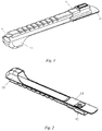
Fig. 1 is a structural view showing the front side of a finger motion aid in a first embodiment; -
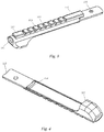
Fig. 2 is a structural view showing the back side of the finger motion aid in the first embodiment; -
Fig. 3 is a structural view showing the front side of a rubber member in the first embodiment; -
Fig. 4 is a structural view showing the back side of the rubber member in the first embodiment; -
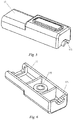
Fig. 5 is a structural view showing the front side of a plastic cover in the first embodiment; -
Fig. 6 is a structural view showing the back side of the plastic cover in the first embodiment; -
Fig. 7 is a structural view of a hook-and-loop fastener in the first embodiment; -
Fig. 8 is a cross-section view of the finger motion aid in the first embodiment; -
Fig. 9 is a structural view of a rehabilitation hand having finger motion aids in a second embodiment; -
Fig. 10 is a structural view of a controller in the second embodiment; -
Fig. 11 is a state diagram of a protective gear when folded in the second embodiment; -
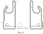
Fig. 12 is a structural view showing the front side of the protective gear when unfolded in the second embodiment; and -
Fig. 13 is a structural view showing the back side of the protective gear when unfolded in the second embodiment. - The above and other technical features and advantages of the present invention are described in more detail below with reference to the accompanying drawings.
- A finger motion aid, as shown in
Figs. 1 and 2 , comprises arubber member 11, aplastic cover 12, a hook-and-loop fastener 13 and a chip 14. - The
rubber member 11 is worn on a finger, and the chip 14 is placed in therubber member 11. After a control signal is received by the chip 14, therubber member 11 is controlled to bend and stretch, thereby driving a patient's finger to bend and stretch. Therubber member 11 is made of a plastic material, and because the initial state of the patient's fingers is bent, the tensile property of therubber member 11 is required to be strong. When a retraction command is received by the chip 14 to force therubber member 11 to retract, the patient's finger is passively stretched to do rehabilitation training, and in that case, therubber member 11 is required to have a good retraction property. - The
rubber member 11 is as shown inFigs. 3 and 4 , a finger sleeve is provided at a front end of therubber member 11, and therubber member 11 is worn on the patient's finger by extending same into the finger sleeve. The finger sleeve has a segment of a flat surface 117 at a position in which the finger sleeve is in contact with a finger pad for supporting the finger. The finger sleeve has an open end 111 and the patient's finger can extend from the open end 111 to facilitate enhancing the touch sense of the patient's finger. An elongated space, which is formed by afirst bridge 112, a plurality ofintermediate bridges 113, a plurality ofgrooves 114 and alast bridge 115, is provided on a front face of therubber member 11, and the chip 14 is placed in the elongated space. The width of the elongated space is greater than the width of the chip. Therubber member 11 worn on the finger can be bent and deformed as the finger of the person is deformed and bent. The width of the elongated space being greater than the width of the chip allows reduced deformation of the chip in the elongated space. Thebridge 112 and thebridge 115 are slightly longer in length, the length of thebridge 112 is in the range of approximately 12-17 mm, and the length of thebridge 115 is in the range of approximately 17-20 mm, thereby preventing the chip 14 from exiting from thebridge 112 and thebridge 115 during bending. There are at least threebridges 113 between thebridge 112 and thebridge 115 that have the width of about 6 mm. There is agroove 114 between twobridges 113 that has the width of 3 mm. The arrangement of thegroove 114 is for the purpose of adding the flexibility of therubber member 11 and thus allowing therubber member 11 to be more closely fitted to the patient's finger during bending and stretching of therubber member 11 so as to assist the patient's finger motion. The curve radian of a curved surface 118 on the back side of therubber member 11 is greater than that of acurved surface 119, and the curved surface 118 is more closely fitted to the patient's finger when therubber member 11 is bent and retracted. Thecurved surface 119 has a smaller curve radian and thus is convenient to fit with the hook-and-loop fastener 13. - The
plastic cover 12, as shown inFigs. 5 and 6 , is used for fixing an electric wire between the chip 14 and the controller to prevent, due to the chip 14 moving together with the movement of the electric wire, therubber member 11 from deviating from the patient's finger and affecting the assistance motion effect. The electric wire connected to the chip 14 is connected to the controller through ahole 121. A hole 122, ahole 116 and a hole 131 (as shown inFig. 7 ) are fixed together by a screw, as shown inFig. 8 . - The hook-and-
loop fastener 13 has a smaller curve radian and thus is convenient to be bonded with a protective gear. One side of the hook-and-loop fastener is fixedly connected to therubber member 11 and theplastic cover 12 by the screw at the hole 131, and the other side thereof is bonded to the protective gear by means of a bonding face. - The finger motion aid suitable for each of the fingers is identical in structure, except that the length of the finger is different and thus the length of the rubber member also varies. The lengths of the fingers of a man and a woman are also different and the fingers of persons of the same gender are different depending on the heights of the persons. As long as the above-mentioned finger motion aid is made into different models, the needs of various persons can be met.
- In the finger motion aid, the control signal is received by the chip, so that the chip is bent and stretched. By placing the chip into the rubber member, the rubber member worn on the patient's finger drives the patient's finger to move as the chip moves, thus assisting the patient's fingers to exercise and gradually recover to health.
- A rehabilitation hand having the finger motion aid as described above, as shown in
Fig. 9 , comprises at least one of a thumb motion aid 1, an indexfinger motion aid 2, a middle finger motion aid 3, a ring finger motion aid 4 and a little finger motion aid 5, and further comprises a controller 6 and a protective gear 7. - The finger motion aids according to the first embodiment can be worn on five fingers of a hand, which are respectively referred to as the thumb motion aid 1, the index
finger motion aid 2, the middle finger motion aid 3, the ring finger motion aid 4 and the little finger motion aid 5. The finger motion aids worn on the fingers are different in length because of the different lengths of the five fingers, and the differences are mainly featured by the different numbers of thebridges 113 and thegrooves 114. Except for that, there is no difference in the structure for the finger motion aids. The finger motion aids are respectively bonded to the protective gear 7 by means of the hook-and-loop fasteners, are convenient to disassemble and assemble, are easy to adjust, and are suitable for various deformed fingers. - The controller 6 is positioned at the back of the hand of the protective gear 7 to facilitate operation and fixed bonding to the protective gear 7. The controller 6 is provided with five identical electric wire sockets 61, and chips on the thumb motion aid 1, the index
finger motion aid 2, the middle finger motion aid 3, the ring finger motion aid 4 and the little finger motion aid 5 are respectively connected to the five electric wire sockets 61 on the controller 6 via electric wires. The controller 6 is further provided with a power switch 62 for controlling power on and off of the controller 6. The controller 6 is further provided with apower socket 63 for connecting with an external power source to energize the controller 6. The controller 6 is used to receive an active assistance signal (a professional rehabilitation person wears a rehabilitation hand to actively perform bending and stretching actions), and synchronously transmit the signal to the chips on the five finger motion aids. Upon receipt of the synchronous signal by the chips on the five finger motion aids, the bending and stretching actions of the same intensity as performed by the professional rehabilitation person are synchronously performed to do rehabilitation training. - The protective gear 7, as shown in
Figs. 11 to 13 , is worn on a palm and a wrist.Fig. 11 shows a state in which the protective gear is folded and the thumb is extended from a hole 71.Figs. 12 and13 respectively show two states of front and back sides of the protective gear 7 when it is unfolded. On the front side, there is a hook-and-loop fastener 72. The hook-and-loop fastener 72 is bonded to the surface of the protective gear when the protective gear is folded for binding and fixation. Ahard sheet 73 is embedded in one end of the protective gear to facilitate operation when the protective gear is folded and bound to the palm and the wrist and to increase the binding tightness. The hard sheet may be a hard structure, such as a steel plate or an aluminum sheet. An end portion 74 has a certain degree of curvature and is disposed such that the hook-and-loop fastener on the end portion 74 is bonded to the protective gear at a position that is close to the thumb, so as not to affect bonding of the indexfinger motion aid 2 to the protective gear 7. The width of a position 75 is relatively large and thus the width of an end portion 76 is reduced, so as to facilitate bonding of the thumb motion aid 1 to the protective gear 7. The protective gear 7 is required to be breathable, dirt-resistant and lightweight, and is convenient for the patient to wear for a long time. In addition, the protective gear 7 is required to be elastic and flexible, and is convenient to wear. The surface of the protective gear 7 is to be bonded with the hook-and-loop fastener, so as to facilitate fixing the finger motion aids of the five fingers. The material of the protective gear 7 may be composite waterproof stretch flannelette, and other materials that accord with the property of the protective gear may be used. - When in use, the protective gear 7 is first worn on the palm and the wrist, then the controller 6 is fixed at the back of the hand of the protective gear 7, and then the five finger motion aids are respectively worn and bonded; and the five finger motion aids are connected to the controller through electric wires, and a power supply of the controller is turned on, so that finger motions can be performed synchronously with the professional rehabilitation person to assist rehabilitation of the patient.
- The patient may wear a finger motion aid for a specific finger depending on a paralysis condition of the finger. If a certain finger is not paralyzed or deformed, it may not wear the finger motion aid, but a finger that is not able to be stretched may wear the finger motion aid.
The preferred embodiments of the present invention have been described above, and are merely illustrative and not restrictive to the present invention. It will be understood by those skilled in the art that many changes, modifications and even equivalents may be made within the scope of the present invention as defined by the appended claims, but would fall within the scope of protection of the present invention.
Claims (6)
- A finger motion aid, comprising:a rubber member (11) for receiving a finger of a hand of a patient;a plastic cover (12);a finger sleeve is provided at a front end of the rubber member (11), the finger sleeve has an open end, the finger of the patient can extend through the open end, and the finger motion aid can be removably secured on the finger by means of the finger sleeve; an elongated space, which is formed by a first bridge (112), a last bridge (115), a plurality of intermediate bridges and a plurality of grooves (114), is provided on a top face of the rubber member (11), and a chip (14) is located in the elongated space; the width of the elongated space is greater than the width of the chip (14);a back side of the rubber member (11) has a curve radian that complements a shape of the finger; andthe plastic cover (12) is disposed on and fixedly connected to the rubber member (11), whereby the finger motion aid further comprises a controller (6) electrically connected to the chip, characterized in thatthe chip (14) in the rubber member (11) is a flexible chip substantially coextensive in length with the rubber member (11), whereby the chip (14) bends and stretches in response to a signal transmitted from the controller (6), the controller is electronically operable with a protective gear (7) worn by a guide hand of a rehabilitation assistant, so that when fingers of the guide hand are bent and stretched, the chip in the rubber member drives the finger of the patient to bend and stretch along a length of the rubber member (11) in synchrony with corresponding finger movement of the guide hand.
- The finger motion aid according to claim 1, characterized in that the length of each of the first bridge (112) and the last bridge (115) is greater than the length of each of the intermediate bridges to prevent the chip (14) from exiting from the first bridge (112) and the last bridge (115).
- The finger motion aid according to claim 2, characterized in that the finger sleeve has a segment of a flat surface (117) at a position in which the finger sleeve is in contact with a finger pad for supporting the finger.
- The finger motion aid according to claim 1, characterized in that the finger motion aid further comprises a hook-and-loop fastener, which is disposed underneath and fixedly connected to the rubber member (11).
- A rehabilitation hand having the finger motion aid according to any one of claims 1-4, the rehabilitation hand comprising at least one of a thumb motion aid, an index finger motion aid, a middle finger motion aid, a ring finger motion aid and a little finger motion aid, and further comprising a protective gear (7), characterized in that the controller (6) is disposed on and fixedly connected to the protective gear (7);
the controller (6) is electrically connected to chips (14) on the thumb motion aid, the index finger motion aid, the middle finger motion aid, the ring finger motion aid and the little finger motion aid, respectively; an active assistance signal is received by the controller (6) and synchronously transmitted to the chips (14) on the five finger motion aids, so that the chips (14) on the five finger motion aids are forced to synchronously perform an action of the same intensity as performed by a professional rehabilitation person;
hook-and-loop fasteners on the thumb motion aid, the index finger motion aid, the middle finger motion aid, the ring finger motion aid and the little finger motion aid are respectively bonded to the protective gear (7); and
the protective gear (7) is fixed on a wrist and a palm. - The rehabilitation hand according to claim 5, characterized in that the protective gear (7) is embedded with a hard sheet at one end to facilitate wearing the protective gear (7) on the wrist and the palm.
Applications Claiming Priority (2)
| Application Number | Priority Date | Filing Date | Title |
|---|---|---|---|
| CN201710552260.3A CN107157713B (en) | 2017-07-07 | 2017-07-07 | A kind of finger motion auxiliary member and the rehabilitation hand with the auxiliary member |
| PCT/CN2018/094198 WO2019007313A1 (en) | 2017-07-07 | 2018-07-03 | Finger movement aid and rehabilitation hand comprising same |
Publications (3)
| Publication Number | Publication Date |
|---|---|
| EP3632395A1 EP3632395A1 (en) | 2020-04-08 |
| EP3632395A4 EP3632395A4 (en) | 2020-06-17 |
| EP3632395B1 true EP3632395B1 (en) | 2021-06-16 |
Family
ID=59823289
Family Applications (1)
| Application Number | Title | Priority Date | Filing Date |
|---|---|---|---|
| EP18828345.1A Active EP3632395B1 (en) | 2017-07-07 | 2018-07-03 | Finger movement aid and rehabilitation hand comprising same |
Country Status (6)
| Country | Link |
|---|---|
| US (1) | US10993869B2 (en) |
| EP (1) | EP3632395B1 (en) |
| JP (1) | JP6802394B2 (en) |
| CN (1) | CN107157713B (en) |
| ES (1) | ES2881619T3 (en) |
| WO (1) | WO2019007313A1 (en) |
Families Citing this family (8)
| Publication number | Priority date | Publication date | Assignee | Title |
|---|---|---|---|---|
| CN107157713B (en) | 2017-07-07 | 2018-08-07 | 北京恒通信佳科技发展有限公司 | A kind of finger motion auxiliary member and the rehabilitation hand with the auxiliary member |
| CN110151493B (en) * | 2019-06-24 | 2024-01-19 | 深圳睿瀚医疗科技有限公司 | Five-finger linkage grasping manipulator |
| CN110478195A (en) * | 2019-09-11 | 2019-11-22 | 中山长曜医疗器材有限公司 | A kind of sensor device and integral type finger joint recovery gloves |
| USD942023S1 (en) * | 2019-10-21 | 2022-01-25 | Neofect Co., Ltd. | Hand rehabilitation training apparatus |
| TWI760117B (en) * | 2021-02-24 | 2022-04-01 | 財團法人鞋類暨運動休閒科技研發中心 | Rehabilitation device |
| CN113456424B (en) * | 2021-07-08 | 2023-11-10 | 青岛市胶州中心医院 | Wearable medical rehabilitation finger training device |
| US12303447B2 (en) * | 2022-01-19 | 2025-05-20 | Animo Bionics Corp. | Telekinetic bionic glove assembly |
| CN114587941A (en) * | 2022-04-07 | 2022-06-07 | 荆门市中医医院(荆门市石化医院) | A kind of exercise aid device for rehabilitation nursing |
Family Cites Families (43)
| Publication number | Priority date | Publication date | Assignee | Title |
|---|---|---|---|---|
| US3581740A (en) * | 1969-09-02 | 1971-06-01 | Kuss & Co R L | Inflatable device for arthritic therapy |
| US3756222A (en) * | 1971-12-27 | 1973-09-04 | Univ Kansas State | Electrically driven hand exerciser |
| US3937215A (en) * | 1975-06-03 | 1976-02-10 | The United States Of America As Represented By The United States National Aeronautics And Space Administration Office Of General Counsel-Code Gp | Therapeutic hand exerciser |
| US4671258A (en) * | 1984-01-12 | 1987-06-09 | Barthlome Donald E | Therapeutic multiple joint exerciser |
| US5178137A (en) * | 1990-03-16 | 1993-01-12 | Motus, Inc. | Segmented dynamic splint |
| US5103807A (en) * | 1991-04-26 | 1992-04-14 | John Makaran | Shape memory alloy orthotic device |
| US5261393A (en) * | 1992-09-17 | 1993-11-16 | Norman Weinzweig | Removable flexible finger covering with fingertip connector clip |
| US5697892A (en) * | 1995-09-13 | 1997-12-16 | Sutter Corporation | Continuous passive motion device for the hand and a method of using the same |
| US6010468A (en) * | 1998-03-05 | 2000-01-04 | The Discovery Group, Llc | Foot flexion device |
| US7001352B2 (en) * | 2002-02-25 | 2006-02-21 | Saebo, Inc. | Dynamic resting hand splint |
| WO2006063347A2 (en) * | 2004-12-10 | 2006-06-15 | Saebo, Inc. | Dynamic hand splints |
| SE530293C2 (en) * | 2006-09-01 | 2008-04-22 | Hans Von Holst | Finger glove for use by e.g. manual worker, has artificial tendons fixed to or connected to yoke, where pulling force exerted on artificial tendons of glove finger bends finger enclosed in glove finger inwards towards palm |
| CN101433491B (en) * | 2008-12-05 | 2010-12-22 | 华中科技大学 | Multi-degree-of-freedom wearable hand function rehabilitation training robot and its control system |
| JP4716456B2 (en) * | 2009-10-05 | 2011-07-06 | 圭治郎 山本 | Joint motion support device |
| DE202009017473U1 (en) | 2009-12-23 | 2011-05-05 | Puma Aktiengesellschaft Rudolf Dassler Sport | Reinforcing element for a glove and glove, in particular goalkeeper glove, with such a reinforcing element |
| WO2011117901A1 (en) * | 2010-03-23 | 2011-09-29 | Idrogenet S.R.L. | A hand rehabilitation device |
| US20120059290A1 (en) * | 2010-09-02 | 2012-03-08 | Yip Joanne Yiu Wan | Wearable device for finger rehabilitation |
| US8622939B2 (en) * | 2010-09-03 | 2014-01-07 | Bes Rehab Ltd. | Apparatus for manipulating joints of a limb |
| CN101940522B (en) * | 2010-09-28 | 2013-09-11 | 陈招富 | Microcomputer controlled finger movement device |
| JP5920805B2 (en) * | 2011-05-31 | 2016-05-18 | 国立大学法人電気通信大学 | Finger extension exercise support device |
| US9120220B2 (en) * | 2012-02-29 | 2015-09-01 | GM Global Technology Operations LLC | Control of a glove-based grasp assist device |
| US9764190B2 (en) * | 2012-06-13 | 2017-09-19 | Saebo, Inc. | Dynamic hand splints |
| US9387112B2 (en) * | 2013-02-28 | 2016-07-12 | Marvin Frank Bryant | Myoelectric hand orthosis |
| US10184500B2 (en) * | 2013-10-29 | 2019-01-22 | President And Fellows Of Harvard College | Multi-segment reinforced actuators and applications |
| WO2015095459A1 (en) * | 2013-12-18 | 2015-06-25 | Board Of Regents, The University Of Texas System | Robotic finger exoskeleton |
| US10248200B2 (en) * | 2014-03-02 | 2019-04-02 | Drexel University | Wearable devices, wearable robotic devices, gloves, and systems, methods, and computer program products interacting with the same |
| US10478370B2 (en) * | 2014-06-30 | 2019-11-19 | Rehabilitation Institute Of Chicago | Actuated glove orthosis and related methods |
| CN204121369U (en) * | 2014-08-06 | 2015-01-28 | 张晓雲 | Maintenance and rehabilitation device for the function of the metacarpophalangeal joints of the hand |
| EP3226824B1 (en) * | 2014-12-04 | 2019-06-19 | Telerobot Labs S.r.l. | Aid device for the movement and/or rehabilitation of one or more fingers of a hand |
| US10912701B2 (en) * | 2015-01-07 | 2021-02-09 | The Board Of Regents Of The University Of Texas System | Fluid-driven actuators and related methods |
| CN107249833A (en) * | 2015-01-12 | 2017-10-13 | 哈佛学院院长及董事 | For software robot and the sensor of soft actuator |
| KR101541082B1 (en) * | 2015-01-23 | 2015-08-03 | 주식회사 네오펙트 | System and method for rehabilitation exercise of the hands |
| CN104586608B (en) * | 2015-02-05 | 2017-04-05 | 华南理工大学 | The wearable power-assisted finger controlled based on myoelectricity and its control method |
| US9897492B2 (en) * | 2015-05-06 | 2018-02-20 | K-Jump Health Co., Ltd. | Method for manufacturing temperature measure units of thermometers |
| CN204910720U (en) | 2015-07-06 | 2015-12-30 | 陈元森 | Side insert finger insert and its glove holder combination |
| CN205181730U (en) * | 2015-12-22 | 2016-04-27 | 崔国华 | Hand rehabilitative apparatus |
| CA3015906A1 (en) * | 2016-02-25 | 2017-08-31 | Cornell University | Waveguides for use in sensors or displays |
| CN205758934U (en) * | 2016-04-01 | 2016-12-07 | 北京所乐思国际商务有限公司 | A kind of easy donning joint motions auxiliary device |
| CN205698416U (en) | 2016-04-01 | 2016-11-23 | 北京所乐思国际商务有限公司 | A kind of joint motions auxiliary device of independent subjoint |
| CN106625733A (en) | 2017-02-24 | 2017-05-10 | 张帆 | Novel flexible finger |
| US11129766B2 (en) * | 2017-04-14 | 2021-09-28 | The Chinese University Of Hong Kong | Flexibly driven robotic hands |
| US20180335842A1 (en) * | 2017-05-19 | 2018-11-22 | Axonvr Corporation | Haptic feedback glove |
| CN107157713B (en) | 2017-07-07 | 2018-08-07 | 北京恒通信佳科技发展有限公司 | A kind of finger motion auxiliary member and the rehabilitation hand with the auxiliary member |
-
2017
- 2017-07-07 CN CN201710552260.3A patent/CN107157713B/en active Active
-
2018
- 2018-07-03 EP EP18828345.1A patent/EP3632395B1/en active Active
- 2018-07-03 ES ES18828345T patent/ES2881619T3/en active Active
- 2018-07-03 US US16/626,536 patent/US10993869B2/en active Active
- 2018-07-03 WO PCT/CN2018/094198 patent/WO2019007313A1/en not_active Ceased
- 2018-07-03 JP JP2019568337A patent/JP6802394B2/en active Active
Also Published As
| Publication number | Publication date |
|---|---|
| CN107157713A (en) | 2017-09-15 |
| EP3632395A1 (en) | 2020-04-08 |
| CN107157713B (en) | 2018-08-07 |
| US10993869B2 (en) | 2021-05-04 |
| JP6802394B2 (en) | 2020-12-16 |
| ES2881619T3 (en) | 2021-11-30 |
| US20200281797A1 (en) | 2020-09-10 |
| WO2019007313A1 (en) | 2019-01-10 |
| EP3632395A4 (en) | 2020-06-17 |
| JP2020526244A (en) | 2020-08-31 |
Similar Documents
| Publication | Publication Date | Title |
|---|---|---|
| US10993869B2 (en) | Finger motion aid and rehabilitation hand having same | |
| ES2742326T3 (en) | Apparatus and method to rehabilitate an injured limb | |
| CN102811690B (en) | hand rehabilitation device | |
| CN105457236B (en) | Rehabilitation training hand and recovery training method | |
| EP3226824B1 (en) | Aid device for the movement and/or rehabilitation of one or more fingers of a hand | |
| JP6734927B2 (en) | Motion support device | |
| CN110731880B (en) | A flexible rehabilitation exoskeleton glove | |
| EP3414061B1 (en) | A device for enhancing a user's grasping capability | |
| US8622939B2 (en) | Apparatus for manipulating joints of a limb | |
| WO2019007314A1 (en) | Knuckle rehabilitation exercise aid | |
| CN111374862B (en) | A hybrid drive bionic upper limb rehabilitation training device | |
| CN104983546A (en) | Stewart type wearable wrist rehabilitation robot | |
| KR20150062456A (en) | Training robotic device for the finger | |
| CN102824244B (en) | Non-invasive dynamic finger bone traction brace | |
| CN203777261U (en) | Hand metacarpal finger rehabilitation exercise device | |
| JP6372912B2 (en) | Rehabilitation assistance device | |
| CN104771288A (en) | Hand metacarpal finger rehabilitation practice method and device thereof | |
| TW201526948A (en) | Hand palm and finger rehabilitation practicing method and device | |
| CN110665192B (en) | Recovered type ectoskeleton gloves robot | |
| CN217245400U (en) | All-round touch perception gloves | |
| CN208710407U (en) | A kind of finger movement auxiliary member and the rehabilitation hand with the auxiliary member | |
| CN116650278A (en) | Active and passive rehabilitation gloves for flexible hand joints | |
| CN207822367U (en) | A kind of adjustable finger rehabilitation training device | |
| CN115813718B (en) | A soft rehabilitation glove | |
| Stellin et al. | Development and test of fex, a fingers extending exoskeleton for rehabilitation and regaining mobility |
Legal Events
| Date | Code | Title | Description |
|---|---|---|---|
| STAA | Information on the status of an ep patent application or granted ep patent |
Free format text: STATUS: THE INTERNATIONAL PUBLICATION HAS BEEN MADE |
|
| PUAI | Public reference made under article 153(3) epc to a published international application that has entered the european phase |
Free format text: ORIGINAL CODE: 0009012 |
|
| STAA | Information on the status of an ep patent application or granted ep patent |
Free format text: STATUS: REQUEST FOR EXAMINATION WAS MADE |
|
| 17P | Request for examination filed |
Effective date: 20191230 |
|
| AK | Designated contracting states |
Kind code of ref document: A1 Designated state(s): AL AT BE BG CH CY CZ DE DK EE ES FI FR GB GR HR HU IE IS IT LI LT LU LV MC MK MT NL NO PL PT RO RS SE SI SK SM TR |
|
| AX | Request for extension of the european patent |
Extension state: BA ME |
|
| R17P | Request for examination filed (corrected) |
Effective date: 20191230 |
|
| RIN1 | Information on inventor provided before grant (corrected) |
Inventor name: YAMAMOTO, KEIJIRON Inventor name: YANG, KEQIANG Inventor name: MAO, ZHENWEI |
|
| A4 | Supplementary search report drawn up and despatched |
Effective date: 20200513 |
|
| RIC1 | Information provided on ipc code assigned before grant |
Ipc: A61H 1/02 20060101AFI20200508BHEP |
|
| RIN1 | Information on inventor provided before grant (corrected) |
Inventor name: YAMAMOTO, KEIJIRON Inventor name: YANG, KEQIANG Inventor name: MAO, ZHENWEI |
|
| DAV | Request for validation of the european patent (deleted) | ||
| DAX | Request for extension of the european patent (deleted) | ||
| GRAP | Despatch of communication of intention to grant a patent |
Free format text: ORIGINAL CODE: EPIDOSNIGR1 |
|
| STAA | Information on the status of an ep patent application or granted ep patent |
Free format text: STATUS: GRANT OF PATENT IS INTENDED |
|
| INTG | Intention to grant announced |
Effective date: 20210201 |
|
| GRAS | Grant fee paid |
Free format text: ORIGINAL CODE: EPIDOSNIGR3 |
|
| GRAA | (expected) grant |
Free format text: ORIGINAL CODE: 0009210 |
|
| STAA | Information on the status of an ep patent application or granted ep patent |
Free format text: STATUS: THE PATENT HAS BEEN GRANTED |
|
| AK | Designated contracting states |
Kind code of ref document: B1 Designated state(s): AL AT BE BG CH CY CZ DE DK EE ES FI FR GB GR HR HU IE IS IT LI LT LU LV MC MK MT NL NO PL PT RO RS SE SI SK SM TR |
|
| REG | Reference to a national code |
Ref country code: GB Ref legal event code: FG4D |
|
| REG | Reference to a national code |
Ref country code: CH Ref legal event code: EP |
|
| REG | Reference to a national code |
Ref country code: DE Ref legal event code: R096 Ref document number: 602018018819 Country of ref document: DE |
|
| REG | Reference to a national code |
Ref country code: AT Ref legal event code: REF Ref document number: 1401721 Country of ref document: AT Kind code of ref document: T Effective date: 20210715 |
|
| REG | Reference to a national code |
Ref country code: IE Ref legal event code: FG4D |
|
| REG | Reference to a national code |
Ref country code: LT Ref legal event code: MG9D |
|
| PG25 | Lapsed in a contracting state [announced via postgrant information from national office to epo] |
Ref country code: LT Free format text: LAPSE BECAUSE OF FAILURE TO SUBMIT A TRANSLATION OF THE DESCRIPTION OR TO PAY THE FEE WITHIN THE PRESCRIBED TIME-LIMIT Effective date: 20210616 Ref country code: HR Free format text: LAPSE BECAUSE OF FAILURE TO SUBMIT A TRANSLATION OF THE DESCRIPTION OR TO PAY THE FEE WITHIN THE PRESCRIBED TIME-LIMIT Effective date: 20210616 Ref country code: FI Free format text: LAPSE BECAUSE OF FAILURE TO SUBMIT A TRANSLATION OF THE DESCRIPTION OR TO PAY THE FEE WITHIN THE PRESCRIBED TIME-LIMIT Effective date: 20210616 Ref country code: BG Free format text: LAPSE BECAUSE OF FAILURE TO SUBMIT A TRANSLATION OF THE DESCRIPTION OR TO PAY THE FEE WITHIN THE PRESCRIBED TIME-LIMIT Effective date: 20210916 |
|
| REG | Reference to a national code |
Ref country code: AT Ref legal event code: MK05 Ref document number: 1401721 Country of ref document: AT Kind code of ref document: T Effective date: 20210616 |
|
| REG | Reference to a national code |
Ref country code: NL Ref legal event code: MP Effective date: 20210616 |
|
| PG25 | Lapsed in a contracting state [announced via postgrant information from national office to epo] |
Ref country code: GR Free format text: LAPSE BECAUSE OF FAILURE TO SUBMIT A TRANSLATION OF THE DESCRIPTION OR TO PAY THE FEE WITHIN THE PRESCRIBED TIME-LIMIT Effective date: 20210917 Ref country code: NO Free format text: LAPSE BECAUSE OF FAILURE TO SUBMIT A TRANSLATION OF THE DESCRIPTION OR TO PAY THE FEE WITHIN THE PRESCRIBED TIME-LIMIT Effective date: 20210916 Ref country code: LV Free format text: LAPSE BECAUSE OF FAILURE TO SUBMIT A TRANSLATION OF THE DESCRIPTION OR TO PAY THE FEE WITHIN THE PRESCRIBED TIME-LIMIT Effective date: 20210616 Ref country code: SE Free format text: LAPSE BECAUSE OF FAILURE TO SUBMIT A TRANSLATION OF THE DESCRIPTION OR TO PAY THE FEE WITHIN THE PRESCRIBED TIME-LIMIT Effective date: 20210616 Ref country code: RS Free format text: LAPSE BECAUSE OF FAILURE TO SUBMIT A TRANSLATION OF THE DESCRIPTION OR TO PAY THE FEE WITHIN THE PRESCRIBED TIME-LIMIT Effective date: 20210616 |
|
| REG | Reference to a national code |
Ref country code: ES Ref legal event code: FG2A Ref document number: 2881619 Country of ref document: ES Kind code of ref document: T3 Effective date: 20211130 |
|
| PG25 | Lapsed in a contracting state [announced via postgrant information from national office to epo] |
Ref country code: SK Free format text: LAPSE BECAUSE OF FAILURE TO SUBMIT A TRANSLATION OF THE DESCRIPTION OR TO PAY THE FEE WITHIN THE PRESCRIBED TIME-LIMIT Effective date: 20210616 Ref country code: EE Free format text: LAPSE BECAUSE OF FAILURE TO SUBMIT A TRANSLATION OF THE DESCRIPTION OR TO PAY THE FEE WITHIN THE PRESCRIBED TIME-LIMIT Effective date: 20210616 Ref country code: SM Free format text: LAPSE BECAUSE OF FAILURE TO SUBMIT A TRANSLATION OF THE DESCRIPTION OR TO PAY THE FEE WITHIN THE PRESCRIBED TIME-LIMIT Effective date: 20210616 Ref country code: PT Free format text: LAPSE BECAUSE OF FAILURE TO SUBMIT A TRANSLATION OF THE DESCRIPTION OR TO PAY THE FEE WITHIN THE PRESCRIBED TIME-LIMIT Effective date: 20211018 Ref country code: NL Free format text: LAPSE BECAUSE OF FAILURE TO SUBMIT A TRANSLATION OF THE DESCRIPTION OR TO PAY THE FEE WITHIN THE PRESCRIBED TIME-LIMIT Effective date: 20210616 Ref country code: RO Free format text: LAPSE BECAUSE OF FAILURE TO SUBMIT A TRANSLATION OF THE DESCRIPTION OR TO PAY THE FEE WITHIN THE PRESCRIBED TIME-LIMIT Effective date: 20210616 Ref country code: CZ Free format text: LAPSE BECAUSE OF FAILURE TO SUBMIT A TRANSLATION OF THE DESCRIPTION OR TO PAY THE FEE WITHIN THE PRESCRIBED TIME-LIMIT Effective date: 20210616 Ref country code: AT Free format text: LAPSE BECAUSE OF FAILURE TO SUBMIT A TRANSLATION OF THE DESCRIPTION OR TO PAY THE FEE WITHIN THE PRESCRIBED TIME-LIMIT Effective date: 20210616 |
|
| PG25 | Lapsed in a contracting state [announced via postgrant information from national office to epo] |
Ref country code: PL Free format text: LAPSE BECAUSE OF FAILURE TO SUBMIT A TRANSLATION OF THE DESCRIPTION OR TO PAY THE FEE WITHIN THE PRESCRIBED TIME-LIMIT Effective date: 20210616 |
|
| REG | Reference to a national code |
Ref country code: CH Ref legal event code: PL |
|
| REG | Reference to a national code |
Ref country code: DE Ref legal event code: R097 Ref document number: 602018018819 Country of ref document: DE |
|
| PG25 | Lapsed in a contracting state [announced via postgrant information from national office to epo] |
Ref country code: MC Free format text: LAPSE BECAUSE OF FAILURE TO SUBMIT A TRANSLATION OF THE DESCRIPTION OR TO PAY THE FEE WITHIN THE PRESCRIBED TIME-LIMIT Effective date: 20210616 |
|
| REG | Reference to a national code |
Ref country code: BE Ref legal event code: MM Effective date: 20210731 |
|
| PLBE | No opposition filed within time limit |
Free format text: ORIGINAL CODE: 0009261 |
|
| STAA | Information on the status of an ep patent application or granted ep patent |
Free format text: STATUS: NO OPPOSITION FILED WITHIN TIME LIMIT |
|
| PG25 | Lapsed in a contracting state [announced via postgrant information from national office to epo] |
Ref country code: LI Free format text: LAPSE BECAUSE OF NON-PAYMENT OF DUE FEES Effective date: 20210731 Ref country code: DK Free format text: LAPSE BECAUSE OF FAILURE TO SUBMIT A TRANSLATION OF THE DESCRIPTION OR TO PAY THE FEE WITHIN THE PRESCRIBED TIME-LIMIT Effective date: 20210616 Ref country code: CH Free format text: LAPSE BECAUSE OF NON-PAYMENT OF DUE FEES Effective date: 20210731 |
|
| 26N | No opposition filed |
Effective date: 20220317 |
|
| PG25 | Lapsed in a contracting state [announced via postgrant information from national office to epo] |
Ref country code: LU Free format text: LAPSE BECAUSE OF NON-PAYMENT OF DUE FEES Effective date: 20210703 Ref country code: AL Free format text: LAPSE BECAUSE OF FAILURE TO SUBMIT A TRANSLATION OF THE DESCRIPTION OR TO PAY THE FEE WITHIN THE PRESCRIBED TIME-LIMIT Effective date: 20210616 |
|
| PG25 | Lapsed in a contracting state [announced via postgrant information from national office to epo] |
Ref country code: IE Free format text: LAPSE BECAUSE OF NON-PAYMENT OF DUE FEES Effective date: 20210703 Ref country code: BE Free format text: LAPSE BECAUSE OF NON-PAYMENT OF DUE FEES Effective date: 20210731 |
|
| PG25 | Lapsed in a contracting state [announced via postgrant information from national office to epo] |
Ref country code: CY Free format text: LAPSE BECAUSE OF FAILURE TO SUBMIT A TRANSLATION OF THE DESCRIPTION OR TO PAY THE FEE WITHIN THE PRESCRIBED TIME-LIMIT Effective date: 20210616 |
|
| PG25 | Lapsed in a contracting state [announced via postgrant information from national office to epo] |
Ref country code: HU Free format text: LAPSE BECAUSE OF FAILURE TO SUBMIT A TRANSLATION OF THE DESCRIPTION OR TO PAY THE FEE WITHIN THE PRESCRIBED TIME-LIMIT; INVALID AB INITIO Effective date: 20180703 |
|
| PG25 | Lapsed in a contracting state [announced via postgrant information from national office to epo] |
Ref country code: MK Free format text: LAPSE BECAUSE OF FAILURE TO SUBMIT A TRANSLATION OF THE DESCRIPTION OR TO PAY THE FEE WITHIN THE PRESCRIBED TIME-LIMIT Effective date: 20210616 |
|
| PG25 | Lapsed in a contracting state [announced via postgrant information from national office to epo] |
Ref country code: MT Free format text: LAPSE BECAUSE OF FAILURE TO SUBMIT A TRANSLATION OF THE DESCRIPTION OR TO PAY THE FEE WITHIN THE PRESCRIBED TIME-LIMIT Effective date: 20210616 |
|
| PG25 | Lapsed in a contracting state [announced via postgrant information from national office to epo] |
Ref country code: TR Free format text: LAPSE BECAUSE OF FAILURE TO SUBMIT A TRANSLATION OF THE DESCRIPTION OR TO PAY THE FEE WITHIN THE PRESCRIBED TIME-LIMIT Effective date: 20210616 |
|
| PGFP | Annual fee paid to national office [announced via postgrant information from national office to epo] |
Ref country code: DE Payment date: 20251118 Year of fee payment: 8 |
|
| PGFP | Annual fee paid to national office [announced via postgrant information from national office to epo] |
Ref country code: GB Payment date: 20251117 Year of fee payment: 8 |
|
| PGFP | Annual fee paid to national office [announced via postgrant information from national office to epo] |
Ref country code: IT Payment date: 20251121 Year of fee payment: 8 |
|
| PGFP | Annual fee paid to national office [announced via postgrant information from national office to epo] |
Ref country code: FR Payment date: 20251117 Year of fee payment: 8 |
|
| PGFP | Annual fee paid to national office [announced via postgrant information from national office to epo] |
Ref country code: ES Payment date: 20251121 Year of fee payment: 8 |