EP3632329A1 - Câble de rallonge pour un système à ultrasons - Google Patents
Câble de rallonge pour un système à ultrasons Download PDFInfo
- Publication number
- EP3632329A1 EP3632329A1 EP18198803.1A EP18198803A EP3632329A1 EP 3632329 A1 EP3632329 A1 EP 3632329A1 EP 18198803 A EP18198803 A EP 18198803A EP 3632329 A1 EP3632329 A1 EP 3632329A1
- Authority
- EP
- European Patent Office
- Prior art keywords
- electrical
- connector
- console
- ecct
- electrically connected
- Prior art date
- Legal status (The legal status is an assumption and is not a legal conclusion. Google has not performed a legal analysis and makes no representation as to the accuracy of the status listed.)
- Withdrawn
Links
Images

Classifications
-
- A—HUMAN NECESSITIES
- A61—MEDICAL OR VETERINARY SCIENCE; HYGIENE
- A61B—DIAGNOSIS; SURGERY; IDENTIFICATION
- A61B8/00—Diagnosis using ultrasonic, sonic or infrasonic waves
- A61B8/56—Details of data transmission or power supply
-
- A—HUMAN NECESSITIES
- A61—MEDICAL OR VETERINARY SCIENCE; HYGIENE
- A61B—DIAGNOSIS; SURGERY; IDENTIFICATION
- A61B8/00—Diagnosis using ultrasonic, sonic or infrasonic waves
- A61B8/08—Detecting organic movements or changes, e.g. tumours, cysts, swellings
- A61B8/0833—Detecting organic movements or changes, e.g. tumours, cysts, swellings involving detecting or locating foreign bodies or organic structures
- A61B8/0841—Detecting organic movements or changes, e.g. tumours, cysts, swellings involving detecting or locating foreign bodies or organic structures for locating instruments
-
- A—HUMAN NECESSITIES
- A61—MEDICAL OR VETERINARY SCIENCE; HYGIENE
- A61B—DIAGNOSIS; SURGERY; IDENTIFICATION
- A61B8/00—Diagnosis using ultrasonic, sonic or infrasonic waves
- A61B8/58—Testing, adjusting or calibrating the diagnostic device
-
- B—PERFORMING OPERATIONS; TRANSPORTING
- B06—GENERATING OR TRANSMITTING MECHANICAL VIBRATIONS IN GENERAL
- B06B—METHODS OR APPARATUS FOR GENERATING OR TRANSMITTING MECHANICAL VIBRATIONS OF INFRASONIC, SONIC, OR ULTRASONIC FREQUENCY, e.g. FOR PERFORMING MECHANICAL WORK IN GENERAL
- B06B1/00—Methods or apparatus for generating mechanical vibrations of infrasonic, sonic, or ultrasonic frequency
-
- H—ELECTRICITY
- H01—ELECTRIC ELEMENTS
- H01R—ELECTRICALLY-CONDUCTIVE CONNECTIONS; STRUCTURAL ASSOCIATIONS OF A PLURALITY OF MUTUALLY-INSULATED ELECTRICAL CONNECTING ELEMENTS; COUPLING DEVICES; CURRENT COLLECTORS
- H01R3/00—Electrically-conductive connections not otherwise provided for
Definitions
- the invention relates to an extension cable.
- the extension cable finds particular application in an ultrasound system.
- the ultrasound system is an ultrasound-based position tracking system and the extension cable is used to connect an ultrasound transducer to the ultrasound-based position tracking system.
- ultrasound transducers are increasingly used to gain more information about, or to treat, a patient's anatomy.
- medical devices may be equipped with an ultrasound transducer for use in sensing and actuation applications such as tracking, imaging, and treatment.
- an ultrasound detector is attached to a medical needle and used to track the needle position respective the ultrasound field of a beamforming ultrasound imaging probe based on the timing of ultrasound signals detected by the detector.
- Such ultrasound transducers may be provided with a connector that connects to a corresponding connector mounted on a console.
- the ultrasound signals may subsequently be processed in the console.
- Extension cables are in general known for this purpose.
- the present invention seeks to provide an improved extension cable for use in an ultrasound system.
- the extension cable may be used to electrically connect an ultrasound transducer to a console.
- an extension cable for use in an ultrasound system.
- the extension cable includes a first electrical connector for connecting to a corresponding ultrasound transducer connector, a second electrical connector for connecting to a corresponding console connector, an electrical circuit and an electrical cable.
- the electrical circuit is disposed between the first electrical connector and the electrical cable.
- the electrical cable is disposed between the electrical circuit and the second electrical connector for extending an electrical connection between the ultrasound transducer connector and the console connector.
- the electrical circuit is configured to provide a multiple-state output, the multiple states being voltage levels corresponding to each of i) the electrical circuit not being electrically connected to the console connector via the second electrical connector, ii) the electrical circuit being electrically connected to the console connector via the second electrical connector and the ultrasound transducer connector not being electrically connected to the first electrical connector, and iii) the electrical circuit being electrically connected to the console connector via the second electrical connector and the ultrasound transducer connector being electrically connected to the first electrical connector.
- the extension cable thus has the ability to determine a connection status of its first and/ or second electrical connectors with their corresponding ultrasound transducer and console connectors.
- a conventional extension cable is used to extend a desired path between such a console and ultrasound transducer a user relies upon observing a causality between inputs to the ultrasound transducer and a response observed via the console, to determine that the path has been extended correctly and the system is operating correctly. For example, if the ultrasound transducer is a detector and the console indicates detected ultrasound signal strength, the user relies upon seeing an indication of an expected signal strength on the console in response to an ultrasound test signal.
- such connectors have multiple failure modes including the failure of one or more of its terminals to contact a corresponding terminal in the counterpart connector.
- the electrical circuit further includes a memory configured to store a count value indicative of a) a number of times that a corresponding ultrasound transducer connector has been connected to the first electrical connector based a number of times the voltage level of the multiple state output transitions to the voltage level corresponding to iii) the electrical circuit being electrically connected to the console connector via the second electrical connector and the ultrasound transducer connector being electrically connected to the first electrical connector, and/ or b) a number of times that a corresponding console connector has been connected to the second electrical connector based on a number of times the voltage level of the multiple state output transitions to the voltage level corresponding to ii) the electrical circuit being electrically connected to the console connector via the second electrical connector and the ultrasound transducer connector not being electrically connected to the first electrical connector.
- the memory stores number of connection cycles between one or both of the extension cable's connectors and their corresponding ultrasound transducer and console connectors.
- the count of each of these connection cycles may be used to indicate the need to replace the extension cable and thereby reduce the chance of its failure.
- an extension cable is described with particular reference to an exemplary ultrasound-based position tracking system in which the extension cable connects an ultrasound transducer to a console by means of the extension cable's first and second electrical connectors, together with a corresponding ultrasound transducer connector and a corresponding console connector. It is however to be appreciated that the extension cable finds application in the ultrasound field in general, particularly the medical ultrasound field. Use of the extension cable in ultrasound sensing and actuation application areas such as position tracking, imaging, and treatment is thus also contemplated.
- ultrasound transducer in the specific form of an ultrasound detector, the term ultrasound transducer should be interpreted more broadly as an ultrasound detector, or an ultrasound emitter, or a device that is capable of both detecting and emitting ultrasound signals, or indeed a device that comprises both an ultrasound emitter and an ultrasound detector.
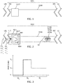
- Fig. 1 illustrates an extension cable that includes first electrical connector FEC, second electrical connector SEC, electrical circuit ECCT and electrical cable ECAB.
- Extension cable EXC1 includes first electrical connector FEC that is suitable FEC for connecting to corresponding ultrasound transducer connector UTC.
- Second electrical connector SEC is suitable for connecting to a corresponding console connector CC.
- Extension cable EXC1 is suitable for use in an ultrasound system in that its electrical connectors FEC, SEC are suitable for carrying electrical signals having frequencies that are typically used in ultrasound applications, i.e. up to a frequency of approximately 1 MHz in some instances, or up to approximately 2 - 10 MHz frequencies in other instances.
- Extension cable EXC1 also includes electrical circuit ECCT and electrical cable ECAB.
- Electrical cable ECAB may include electrical conductors, not shown in Fig. 1 , for communicating ultrasound signals between electrical connectors FEC and SEC.
- Electrical circuit ECCT is disposed between the first electrical connector FEC and the electrical cable ECAB, and electrical cable ECAB is disposed between electrical circuit ECCT and second electrical connector SEC in order to extend an electrical connection between ultrasound transducer connector UTC and console connector CC.
- electrical circuit ECCT is configured to provide a multiple-state output MSOP, the multiple states being voltage levels V 1 , V 2 , V 3 corresponding to each of three connection states.
- the first connection state is that i) the electrical circuit ECCT is not electrically connected to console connector CC via second electrical connector SEC.
- the second connection state is that ii) electrical circuit ECCT is electrically connected to console connector CC via second electrical connector SEC and ultrasound transducer connector UTC is not electrically connected to first electrical connector FEC.
- the third connection state is that iii) electrical circuit ECCT is electrically connected to console connector CC via second electrical connector SEC and ultrasound transducer connector UTC is electrically connected to first electrical connector FEC.
- first electrical connector FEC and second electrical connector SEC are suitable for use as first electrical connector FEC and second electrical connector SEC.
- Connectors types such as USB, IEEE-488 GPIB, D-type, RJ-type, DB-type, coaxial and 8P8C are some non-limiting examples that are contemplated.
- the male or female counterpart is thus suitable for use as corresponding ultrasound transducer connector UTC and corresponding console connector CC.
- electrical circuit ECCT Various configurations of electrical circuit ECCT are contemplated for use in Fig. 1 to provide multiple-state output MSOP. Electrical circuits that include one or more active electronic component are contemplated. Electrical circuits that include only passive electrical components such as resistors, capacitors or diodes, are also contemplated.
- Fig. 4 illustrates an exemplary electrical circuit ECCT that includes an active electronic component TR 1 .
- Active electronic component TR 1 is a transistor in this exemplary configuration and is configured to operate as an electrical switch.
- first electrical conductor FCON and second electrical conductor SCON that form part of electrical cable ECAB provide a potential difference from the console connector CC to electrical circuit ECCT by means of corresponding terminals in console connector CC and second electrical connector SEC.
- Electrical circuit ECCT provides multiple-state output MSOP voltage levels V 1 , V 2 , V 3 at electrical output OP.
- FIG. 3 which illustrates various exemplary multiple-state output MSOP voltage levels V 1 , V 2 , V 3
- the exemplary electrical circuit ECCT of Fig. 1 operates in the following manner.
- a voltage level V 1 is provided at output OP.
- Voltage level V 1 may for example be 0V as illustrated in Fig. 3 during time period TP a due to the absence of any power to electrical circuit ECCT.
- the voltage level V 1 corresponding to the first connection state, i) is provided if the first electrical conductor (FCON) and the second electrical conductor (SCON) is not electrically connected to its corresponding terminal in the console connector (CC).
- electrical circuit ECCT may subsequently be electrically connected to console connector CC via second electrical connector SEC.
- first electrical conductor FCON and second electrical conductor SCON that form part of electrical cable ECAB are configured to provide the exemplary 5V potential difference from the console connector CC to the electrical circuit ECCT by means of corresponding terminals in console connector CC and second electrical connector SEC.
- the second connection state i.e.
- electrical circuit ECCT is electrically connected to console connector CC via second electrical connector SEC and ultrasound transducer connector UTC is not electrically connected to first electrical connector FEC, a voltage level V 2 is provided at output OP.
- resistors R 1 and R 2 pull-up the base of transistor TR 1 to the exemplary 5V potential of first electrical conductor FCON, which switches transistor TR 1 on.
- Output OP is set to a voltage level V 2 , which is determined in part by the relative values of resistors R 3 and R 4 in resistor divider R 3 - R 4 and in part by the current flowing from collector to emitter of TR 1 in its on state.
- first electrical connector FEC may include two or more measurement terminals TM 1 , TM 2 for connecting to corresponding terminals TM' 1 , TM' 2 in ultrasound transducer connector UTC. Measurement terminals TM 1 is connected to electrical circuit ECCT input IP.
- Corresponding terminals TM' 1 , TM' 2 in ultrasound transducer connector UTC are electrically connected together.
- measurement terminals TM 1 , TM 2 are electrically connected together, causing input IP and thus the base of transistor TR 1 to be connected to 0V.
- Transistor TR 1 thus switches off, causing the potential of output OP to be determined by the relative values of resistors R 3 and R 4 .
- input IP is therefore configured to detect whether the ultrasound transducer connector UTC is electrically connected to the first electrical connector FEC.
- corresponding voltage V 3 may for example be approximately 1V, as illustrated in Fig. 3 during time period TP c .
- Voltage level V 3 corresponding to the third connection state is therefore generated based on a value of an impedance measured between the two measurement terminals TM 1 , TM 2 .
- the absolute values of voltage levels V 1 , V 2 , V 3 may be adjusted by changing the potential difference applied to the circuit, or by changing the resistor values, or the on-state resistance of transistor TR 1 .
- a pullup resistor in console connector CC may be connected between an input that connects to electrical circuit ECCT output OP and the exemplary 5V potential of first electrical conductor FCON to further adjust the absolute values of voltage levels V 2 and V 3 by virtue of its effect as a resistive divider.
- there is no local power source permanently attached to electrical circuit ECCT on extension cable ECAB which reduces the technical complexity of the extension cable, in alternative configurations it is contemplated to use such a local power source.
- the voltage provided by such a local power source to electrical circuit ECCT may clearly also determine the absolute values of voltage levels V 1 , V 2 , V 3 .
- the example electrical circuit ECCT of Fig. 4 is only exemplary, and alternative circuits with alternative, or additional active components such as FET transistors, a microprocessor and so forth may also be used.
- Fig. 5 illustrates an exemplary electrical circuit ECCT that includes only passive electrical components.
- the electrical circuit ECCT of Fig. 5 may be used in place of ECCT in Fig. 1 .
- passive components in the form of resistors R a , R b , R c are connected as resistive dividers in order to provide the exemplary aforementioned voltage levels V 1 , V 2 and V 3 .
- a voltage level V 1 is provided at output OP.
- Voltage level V 1 may for example be 0V as illustrated in Fig.
- the voltage level V 1 corresponding to the first connection state, i) is provided if the first electrical conductor FCON and the second electrical conductor SCON is not electrically connected to its corresponding terminal in the console connector CC.
- a voltage level V 2 is provided at output OP.
- Voltage level V 2 may for example be approximately 2.5V as illustrated in Fig. 3 during time period TP b .
- first electrical connector FEC may include two or more measurement terminals TM 1 , TM 2 for connecting to corresponding terminals TM' 1 , TM' 2 in ultrasound transducer connector UTC.
- Corresponding terminals TM' 1 , TM' 2 in ultrasound transducer connector UTC are electrically connected together.
- input IP is connected to SCON by virtue of measurement terminals TM 1 , TM 2 being electrically connected together.
- This causes the voltage of output OP to be determined by the parallel combination of R a and R c , and the resistive divider this forms with R b .
- the voltage level V 3 corresponding to the third connection state is in electrical circuit ECCT in Fig. 5 provided based on a value of an impedance measured between the two measurement terminals TM 1 , TM 2 .
- a pullup resistor in console connector CC may be connected between an input that connects to electrical circuit ECCT output OP and the exemplary 5V potential of first electrical conductor FCON to further adjust the absolute values of voltage levels V 2 and V 3 by virtue of its effect as a resistive divider.
- the example electrical circuit ECCT of Fig. 5 is only exemplary, and alternative circuits with alternative, or additional passive components such as capacitors, diodes and so forth may also be used.
- Fig. 2 illustrates an extension cable EXC2 that includes first electrical connector FEC, second electrical connector SEC, electrical circuit ECCT, electrical cable ECAB and two measurement terminals TM 1 , TM 2 .
- Measurement terminals TM 1 , TM 2 may, as described above, be used to connect to corresponding terminals TM' 1 , TM' 2 in ultrasound transducer connector UTC.
- V 3 provides voltage level V 3 corresponding to iii) electrical circuit ECCT being electrically connected to console connector CC via second electrical connector SEC and ultrasound transducer connector UTC being electrically connected to first electrical connector FEC, based on a value of an impedance measured between the two measurement terminals TM 1 , TM 2 . Additional measurement terminals may be used in a similar manner.
- Electrical cable ECAB illustrated in Fig. 2 may optionally include first electrical conductor FCON and second electrical conductor SCON which are suitable for providing a potential difference from the console connector CC to the electrical circuit ECCT by means of corresponding terminals in the console connector and the second electrical connector.
- electrical cable ECAB may also include shield SH which is configured to shield each electrical conductor SCON, SCON.
- Shield SH may for example cover first electrical conductor FCON and second electrical conductor SCON in the form of a sheath.
- shield SH may be electrically connected to one of the first electrical conductor FCON and the second electrical conductor SCON in order to provide such electrical shielding.
- Such electrical shielding and conductors may also be used in electrical cable ECAB illustrated in Fig. 1 .
- extension cable EXC2 illustrated in Fig. 2 may optionally include a memory MEM.
- Memory MEM is preferably a non-volatile memory.
- Non-volatile random access memory i.e. NVRAM is one suitable example.
- Other suitable examples include flash memory Storage such as electrically erasable programmable read-only memory, i.e. EEPROM, solid-state drive, i.e. SSD, NAND, and so forth.
- Memory MEM may be used to store a count value indicative of a) a number of times that a corresponding ultrasound transducer connector UTC has been connected to the first electrical connector FEC based a number of times the voltage level of the multiple state output MSOP transitions to the voltage level V 3 corresponding to iii) the electrical circuit ECCT being electrically connected to the console connector CC via the second electrical connector SEC and the ultrasound transducer connector UTC being electrically connected to the first electrical connector FEC, and/ or b) a number of times that a corresponding console connector CC has been connected to the second electrical connector SEC based on a number of times the voltage level of the multiple state output MSOP transitions to the voltage level V 2 corresponding to ii) the electrical circuit ECCT being electrically connected to the console connector CC via the second electrical connector SEC and the ultrasound transducer connector UTC not being electrically connected to the first electrical connector FEC.
- Memory MEM may thus store number of connection cycles between one or both of the extension cable's connectors and their corresponding ultrasound transducer and console connectors. Advantageously counts of these connection cycles may be used to indicate the need to replace extension cable EXC2. In so doing the reliability of a system that uses extension cable EXC2 may be improved.
- the count value(s) for a) and b) above may optionally be determined by a counter within electrical circuit ECCT. Alternatively these count value(s) may be determined in a separate console when the console is connected to second electrical connector SEC via console connector CC.
- electrical cable ECAB may optionally also include third electrical conductor TCON that is in communication with electrical circuit ECCT for providing voltage levels V 1 , V 2 , V 3 of multiple-state output MSOP to the console by means of a corresponding terminal in each of the second electrical connector SEC and the console connector CC.
- the third electrical conductor TCON may also be in further communication with memory MEM for receiving the count value from the console CS.
- third electrical conductor TCON acts as a bidirectional signal path.
- Using a bidirectional signal path in this manner reduces the number of electrical conductors in electrical cable ECAB and thereby reduces its weight and improves its flexibility.
- Additional conductors such as optional conductor VCON illustrated in Fig. 2 may also be included within electrical cable ECAB.
- Such conductors may be used in alternative implementations to, for example, provide separate signal paths for communicating multiple state output MSOP to the console and for receiving the count value from the console CS, for communicating ultrasound signals between first electrical connector FEC and second electrical connector SEC, or for other purposes.
- electrical circuit ECCT may be provided with a housing HOU.
- Electrical circuit ECCT may be disposed within housing HOU and first electrical connector FEC may be attached to housing HOU to provide structural support to first electrical connector FEC.
- electrical circuit ECCT may also include an amplifier AMP.
- Amplifier AMP may for example be a charge amplifier or a current amplifier or a voltage amplifier. In one specific implementation the amplifier is a differential charge amplifier.
- Amplifier AMP may be used to amplify electrical signals received from an ultrasound transducer by means of first electrical connector FEC and ultrasound transducer connector UTC. The amplified output may subsequently be communicated to second electrical connector SEC by means of one or more conductors such as electrical conductor VCON. In so doing, the integrity of the ultrasound signals may be preserved following their transmission along the extent of electrical cable ECAB.
- first electrical connector FEC may include two transducer terminals TT 1 , TT 2 for receiving and/ or transmitting electrical signals via corresponding terminals TT' 1 , TT' 2 in ultrasound transducer connector UTC.
- Amplifier AMP is in electrical communication with transducer terminals TT 1 , TT 2 for amplifying the electrical signals. Additional transducer terminals may also be included in connectors UTC and FEC in a similar manner.
- Electrical cable may also include one or more electrical conductors, such as electrical conductor VCON, for transmitting amplified signals to second electrical connector SEC. Such electrical signals maybe further processed by a console, not illustrated in Fig. 2 , when connected to second electrical connector SEC via console connector CC.
- extension cable EXC1, EXC2 may be used in an ultrasound-based position tracking system.
- ultrasound transducer connector UTC is electrically connected to an ultrasound transducer.
- the ultrasound transducer may be a detector connected to ultrasound transducer connector UTC via transducer terminals TT 1 ', TT 2 ' such that when ultrasound transducer connector UTC is connected to first electrical connector FEC, and when second electrical connector SEC is connected to console connector CC, amplifier AMP amplifies detected ultrasound signals and transmits these via amplifier AMP and electrical cable ECAB to console connector CC that is connected to a console.
- the console may be in communication with a beamforming ultrasound imaging probe that is configured to generate an ultrasound field, and include a processor configured to: provide a reconstructed ultrasound image corresponding to the ultrasound field of the beamforming ultrasound imaging probe and to compute a position of the ultrasound transducer of the ultrasound detector respective the ultrasound field based on ultrasound signals transmitted between the beamforming ultrasound imaging probe and the ultrasound transducer, and to provide an icon in the reconstructed ultrasound image based on the computed position of the ultrasound transducer.
- a suitable technique for processing the detected signals and determining the transducer position based on the time of flight of detected ultrasound signals and corresponding beam of the beamforming ultrasound imaging probe in which a maximum signal is detected is disclosed in more detail in document " A Non-disruptive Technology for Robust 3D Tool Tracking for Ultrasound-Guided Interventions” by Jay Mung, Francois Vignon, and Ameet Jain, in MICCAI 2011, Part I, LNCS 6891, pp. 153-160, 2011, A. Martel, and T. Peters (Eds .).
- Fig. 6 illustrates a system SYS that includes extension cable EXC2, console CON and console connector CC.
- Console CON may optionally include the functionality of the aforementioned ultrasound-based position tracking system.
- System SYS comprising extension cable EXC2, console CON, and console connector CC.
- Console CON is connected to extension cable EXC2 via console connector CC and second electrical connector SEC.
- Console CON receives voltage levels V 1 , V 2 , V 3 via third electrical conductor TCON of extension cable EXC2, and shifts voltage level V 1 corresponding to i) the electrical circuit ECCT not being electrically connected to console connector CC via second electrical connector SEC by a predetermined voltage to an adjusted voltage level V' 1 .
- a voltage level shifter or pullup resistor may for example be used to provide this voltage shift.
- Console CON also includes counter CTR that generates a count value indicative of a) a number of times that corresponding ultrasound transducer connector UTC has been connected to first electrical connector FEC, and/ or b) a number of times that corresponding console connector CC has been connected to second electrical connector SEC.
- Counter CTR may be a dedicated counter integrated circuit or its functionality may be carried out by a processor. The count value(s) of counter CTR are based on voltage levels V 1 , V 2 , V 3 and adjusted voltage level V' 1 .
- Counter CTR also provides the count value(s) to memory MEM of electrical circuit ECCT via third electrical conductor TCON and console connector CC.
- console CON of system SYS may further include processor PROC.
- Processor PROC includes instructions which when executed by processor PROC cause processor PROC to process electrical signals received and/ or transmitted between processor console CON and amplifier AMP of electrical circuit ECCT. The instructions cause the processor PROC to process the electrical signals if the count value meets a first count condition, and to suspend processing of the electrical signals if the count value meets a second count condition.
- an arrangement in an alternative implementation is provided.
- the arrangement includes extension cable EXC1 or EXC2 of Fig. 1 or Fig. 2 respectively, console CON, and console connector CC.
- Console CON further includes processor PROC comprising instructions which when executed on processor PROC cause processor PROC to determine a status of a connection between first electrical connector FEC and corresponding ultrasound transducer connector UTC based on the actual voltage level of the multiple-state output MSOP.
- Processor PROC is further configured to i) indicate said status, e.g. to a user and/ or ii) process electrical signals received and/ or transmitted between the processor and the amplifier AMP of the electrical circuit ECCT based on said connection status.
- the present, or current connection status may for example be indicated on a display, for example as an icon or alternatively via an indicator lamp such as a light emitting diode.
- the display of the icon may for example be suspended if it is determined that the present status corresponds to connection state ii); i.e. electrical circuit ECCT being electrically connected to console connector CC via second electrical connector SEC and ultrasound transducer connector UTC not being electrically connected to first electrical connector FEC.
- connection state ii) i.e. electrical circuit ECCT being electrically connected to console connector CC via second electrical connector SEC and ultrasound transducer connector UTC not being electrically connected to first electrical connector FEC.
- this reduces the risk of misinterpreting the ultrasound transducer position when ultrasound transducer connector UTC is not electrically connected to first electrical connector FEC.
- an extension cable has been provided.
- the extension cable includes a first electrical connector for connecting to a corresponding ultrasound transducer connector, a second electrical connector for connecting to a corresponding console connector, an electrical circuit, and an electrical cable.
- the electrical circuit provides a multiple-state output, the multiple states being voltage levels corresponding to each of i) the electrical circuit not being electrically connected to the console connector, ii) the electrical circuit being electrically connected to the console connector and the ultrasound transducer connector not being electrically connected to the first electrical connector, and iii) the electrical circuit being electrically connected to the console connector and the ultrasound transducer connector being electrically connected to the first electrical connector.
- any of the method steps disclosed herein may be recorded in the form of instructions which when executed on a processor cause the processor to carry out such method steps.
- the instructions may be stored on a computer program product.
- the computer program product may be provided by dedicated hardware as well as hardware capable of executing software in association with appropriate software.
- the functions can be provided by a single dedicated processor, by a single shared processor, or by a plurality of individual processors, some of which can be shared.
- processor or “controller” should not be construed to refer exclusively to hardware capable of executing software, and can implicitly include, without limitation, digital signal processor "DSP” hardware, read only memory “ROM” for storing software, random access memory “RAM”, non-volatile storage, etc.
- DSP digital signal processor
- ROM read only memory
- RAM random access memory
- embodiments of the present invention can take the form of a computer program product accessible from a computer-usable or computer-readable storage medium providing program code for use by or in connection with a computer or any instruction execution system.
- a computer-usable or computer readable storage medium can be any apparatus that may include, store, communicate, propagate, or transport the program for use by or in connection with the instruction execution system, apparatus, or device.
- the medium can be an electronic, magnetic, optical, electromagnetic, infrared, or semiconductor system, or apparatus or device, or a propagation medium.
- Examples of a computer-readable medium include a semiconductor or solid state memory, magnetic tape, a removable computer diskette, a random access memory "RAM”, a read-only memory "ROM”, a rigid magnetic disk and an optical disk.
- Current examples of optical disks include compact disk - read only memory "CD-ROM”, compact disk - read/write "CD-R/W”, Blu-RayTM and DVD.
Priority Applications (6)
| Application Number | Priority Date | Filing Date | Title |
|---|---|---|---|
| EP18198803.1A EP3632329A1 (fr) | 2018-10-05 | 2018-10-05 | Câble de rallonge pour un système à ultrasons |
| EP19745155.2A EP3833261B1 (fr) | 2018-08-08 | 2019-07-30 | Câble de rallonge pour un système à ultrasons |
| CN201980052900.1A CN112584769A (zh) | 2018-08-08 | 2019-07-30 | 用于超声系统的延长线缆 |
| US17/265,864 US20210196241A1 (en) | 2018-08-08 | 2019-07-30 | Extension cable for an ultrasound system |
| JP2021502425A JP6984069B2 (ja) | 2018-08-08 | 2019-07-30 | 超音波システム用延長ケーブル |
| PCT/EP2019/070554 WO2020030479A1 (fr) | 2018-08-08 | 2019-07-30 | Câble d'extension pour système à ultrasons |
Applications Claiming Priority (1)
| Application Number | Priority Date | Filing Date | Title |
|---|---|---|---|
| EP18198803.1A EP3632329A1 (fr) | 2018-10-05 | 2018-10-05 | Câble de rallonge pour un système à ultrasons |
Publications (1)
| Publication Number | Publication Date |
|---|---|
| EP3632329A1 true EP3632329A1 (fr) | 2020-04-08 |
Family
ID=63787788
Family Applications (2)
| Application Number | Title | Priority Date | Filing Date |
|---|---|---|---|
| EP18198803.1A Withdrawn EP3632329A1 (fr) | 2018-08-08 | 2018-10-05 | Câble de rallonge pour un système à ultrasons |
| EP19745155.2A Active EP3833261B1 (fr) | 2018-08-08 | 2019-07-30 | Câble de rallonge pour un système à ultrasons |
Family Applications After (1)
| Application Number | Title | Priority Date | Filing Date |
|---|---|---|---|
| EP19745155.2A Active EP3833261B1 (fr) | 2018-08-08 | 2019-07-30 | Câble de rallonge pour un système à ultrasons |
Country Status (4)
| Country | Link |
|---|---|
| US (1) | US20210196241A1 (fr) |
| EP (2) | EP3632329A1 (fr) |
| JP (1) | JP6984069B2 (fr) |
| CN (1) | CN112584769A (fr) |
Citations (4)
| Publication number | Priority date | Publication date | Assignee | Title |
|---|---|---|---|---|
| JPH0320665A (ja) * | 1989-06-19 | 1991-01-29 | Hitachi Ltd | 超音波装置 |
| JP2009061211A (ja) * | 2007-09-10 | 2009-03-26 | Panasonic Corp | 超音波診断装置 |
| US20150032029A1 (en) * | 2009-12-04 | 2015-01-29 | Masimo Corporation | Calibration for multi-stage physiological monitors |
| EP3375378A1 (fr) * | 2017-03-17 | 2018-09-19 | Koninklijke Philips N.V. | Imagerie intravasculaire par ultrasons |
Family Cites Families (10)
| Publication number | Priority date | Publication date | Assignee | Title |
|---|---|---|---|---|
| US5865650A (en) * | 1996-10-22 | 1999-02-02 | Acuson Corporation | Ultrasound adapter |
| JP3722739B2 (ja) * | 2001-10-30 | 2005-11-30 | オリンパス株式会社 | 超音波内視鏡用中継ケーブル |
| US7998072B2 (en) * | 2003-12-19 | 2011-08-16 | Siemens Medical Solutions Usa, Inc. | Probe based digitizing or compression system and method for medical ultrasound |
| JP5046609B2 (ja) * | 2006-10-16 | 2012-10-10 | Hoya株式会社 | 超音波診断装置 |
| CN101677805B (zh) * | 2007-06-01 | 2013-05-29 | 皇家飞利浦电子股份有限公司 | 无线超声探头电缆 |
| JP5470933B2 (ja) * | 2009-03-13 | 2014-04-16 | 日立化成株式会社 | レーザ直接描画露光用感光性樹脂組成物、並びにこれを用いた感光性エレメント、レジストパターンの形成方法及びプリント配線板の製造方法 |
| CN103917889B (zh) * | 2011-09-12 | 2017-07-21 | B-K医疗公司 | 超声成像控制台 |
| JP6294067B2 (ja) * | 2013-12-18 | 2018-03-14 | キヤノンメディカルシステムズ株式会社 | 超音波診断装置 |
| JP6590601B2 (ja) * | 2015-09-04 | 2019-10-16 | キヤノン株式会社 | トランスデューサユニット、トランスデューサユニットを備えた音響波用プローブ、音響波用プローブを備えた光音響装置 |
| EP3370622B8 (fr) * | 2015-11-02 | 2020-04-01 | Koninklijke Philips N.V. | Distribution active d'énergie haute tension pour transducteurs ultrasonores |
-
2018
- 2018-10-05 EP EP18198803.1A patent/EP3632329A1/fr not_active Withdrawn
-
2019
- 2019-07-30 JP JP2021502425A patent/JP6984069B2/ja active Active
- 2019-07-30 US US17/265,864 patent/US20210196241A1/en not_active Abandoned
- 2019-07-30 EP EP19745155.2A patent/EP3833261B1/fr active Active
- 2019-07-30 CN CN201980052900.1A patent/CN112584769A/zh active Pending
Patent Citations (4)
| Publication number | Priority date | Publication date | Assignee | Title |
|---|---|---|---|---|
| JPH0320665A (ja) * | 1989-06-19 | 1991-01-29 | Hitachi Ltd | 超音波装置 |
| JP2009061211A (ja) * | 2007-09-10 | 2009-03-26 | Panasonic Corp | 超音波診断装置 |
| US20150032029A1 (en) * | 2009-12-04 | 2015-01-29 | Masimo Corporation | Calibration for multi-stage physiological monitors |
| EP3375378A1 (fr) * | 2017-03-17 | 2018-09-19 | Koninklijke Philips N.V. | Imagerie intravasculaire par ultrasons |
Non-Patent Citations (1)
| Title |
|---|
| JAY MUNG; FRANCOIS VIGNON; AMEET JAIN: "MICCAI 2011, Part I, LNCS 6891", 2011, article "A Non-disruptive Technology for Robust 3D Tool Tracking for Ultrasound-Guided Interventions", pages: 153 - 160 |
Also Published As
| Publication number | Publication date |
|---|---|
| JP6984069B2 (ja) | 2021-12-17 |
| US20210196241A1 (en) | 2021-07-01 |
| JP2021523803A (ja) | 2021-09-09 |
| CN112584769A (zh) | 2021-03-30 |
| EP3833261A1 (fr) | 2021-06-16 |
| EP3833261B1 (fr) | 2022-02-09 |
Similar Documents
| Publication | Publication Date | Title |
|---|---|---|
| CA2671630C (fr) | Blindage de poignee de catheter | |
| CN101563619A (zh) | 电缆检测系统 | |
| EP2838421B1 (fr) | Câble médical comprenant un circuit d'authentification | |
| US20170138998A1 (en) | Testing Device for Connection Interface and Related Testing Methods | |
| JP2015231515A (ja) | 動き検出部を有する磁気共鳴装置と磁気共鳴検査中に患者の動きを検出する方法 | |
| WO2021137851A1 (fr) | Appareil pour former une fistule | |
| CN106165213A (zh) | 用于针与压电聚合物传感器的连接器 | |
| EP3833261B1 (fr) | Câble de rallonge pour un système à ultrasons | |
| WO2020030479A1 (fr) | Câble d'extension pour système à ultrasons | |
| US10838017B2 (en) | Cable and associated continuity monitoring system and method | |
| US9453868B2 (en) | Test device, test method, and program | |
| KR20240007118A (ko) | 임피던스 보정된 진단 의료 디바이스들 | |
| CN106098105A (zh) | 固态硬盘测试装置 | |
| CN113533219A (zh) | 用于样本检测的测量装置及其安装方法 | |
| CN114615930A (zh) | 用于测量身体中的刺激的感测单元 | |
| US20150080750A1 (en) | Disposable Sensor Device and Monitoring System | |
| KR101653885B1 (ko) | 접속상태 표시기능이 마련된 체인지 어댑터 | |
| EP3912584A1 (fr) | Détection de l'asymétrie dans un dispositif à semi-conducteur bidirectionnel | |
| CN113687153A (zh) | 测试电极质量 | |
| EP3258255A1 (fr) | Système universel de reconnaissance de connexion | |
| JPWO2013140630A1 (ja) | 検査装置、検査方法およびプログラム |
Legal Events
| Date | Code | Title | Description |
|---|---|---|---|
| PUAI | Public reference made under article 153(3) epc to a published international application that has entered the european phase |
Free format text: ORIGINAL CODE: 0009012 |
|
| STAA | Information on the status of an ep patent application or granted ep patent |
Free format text: STATUS: THE APPLICATION HAS BEEN PUBLISHED |
|
| AK | Designated contracting states |
Kind code of ref document: A1 Designated state(s): AL AT BE BG CH CY CZ DE DK EE ES FI FR GB GR HR HU IE IS IT LI LT LU LV MC MK MT NL NO PL PT RO RS SE SI SK SM TR |
|
| AX | Request for extension of the european patent |
Extension state: BA ME |
|
| STAA | Information on the status of an ep patent application or granted ep patent |
Free format text: STATUS: THE APPLICATION IS DEEMED TO BE WITHDRAWN |
|
| 18D | Application deemed to be withdrawn |
Effective date: 20201009 |