EP3632166B1 - Sendeleistungs- und frequenzsprungkonfigurationen für übertragungen von steuerungsinformationen - Google Patents
Sendeleistungs- und frequenzsprungkonfigurationen für übertragungen von steuerungsinformationen Download PDFInfo
- Publication number
- EP3632166B1 EP3632166B1 EP18732546.9A EP18732546A EP3632166B1 EP 3632166 B1 EP3632166 B1 EP 3632166B1 EP 18732546 A EP18732546 A EP 18732546A EP 3632166 B1 EP3632166 B1 EP 3632166B1
- Authority
- EP
- European Patent Office
- Prior art keywords
- tti
- transmit power
- control information
- symbol
- uplink control
- Prior art date
- Legal status (The legal status is an assumption and is not a legal conclusion. Google has not performed a legal analysis and makes no representation as to the accuracy of the status listed.)
- Active
Links
- 230000005540 biological transmission Effects 0.000 title claims description 103
- 238000004891 communication Methods 0.000 claims description 120
- 238000000034 method Methods 0.000 claims description 84
- 230000006870 function Effects 0.000 description 21
- 238000005516 engineering process Methods 0.000 description 9
- 238000010586 diagram Methods 0.000 description 8
- 239000000969 carrier Substances 0.000 description 4
- 230000003287 optical effect Effects 0.000 description 3
- 230000002093 peripheral effect Effects 0.000 description 3
- 230000001360 synchronised effect Effects 0.000 description 3
- 125000004122 cyclic group Chemical group 0.000 description 2
- 230000001627 detrimental effect Effects 0.000 description 2
- 239000000835 fiber Substances 0.000 description 2
- 230000007774 longterm Effects 0.000 description 2
- 230000008520 organization Effects 0.000 description 2
- 239000002245 particle Substances 0.000 description 2
- 238000001774 stimulated Raman spectroscopy Methods 0.000 description 2
- 230000001413 cellular effect Effects 0.000 description 1
- 239000003795 chemical substances by application Substances 0.000 description 1
- 238000004590 computer program Methods 0.000 description 1
- 230000003993 interaction Effects 0.000 description 1
- 238000010295 mobile communication Methods 0.000 description 1
- 238000005070 sampling Methods 0.000 description 1
- 230000011664 signaling Effects 0.000 description 1
Images


Classifications
-
- H—ELECTRICITY
- H04—ELECTRIC COMMUNICATION TECHNIQUE
- H04L—TRANSMISSION OF DIGITAL INFORMATION, e.g. TELEGRAPHIC COMMUNICATION
- H04L5/00—Arrangements affording multiple use of the transmission path
- H04L5/003—Arrangements for allocating sub-channels of the transmission path
- H04L5/0048—Allocation of pilot signals, i.e. of signals known to the receiver
-
- H—ELECTRICITY
- H04—ELECTRIC COMMUNICATION TECHNIQUE
- H04W—WIRELESS COMMUNICATION NETWORKS
- H04W52/00—Power management, e.g. TPC [Transmission Power Control], power saving or power classes
- H04W52/04—TPC
- H04W52/06—TPC algorithms
- H04W52/14—Separate analysis of uplink or downlink
- H04W52/146—Uplink power control
-
- H—ELECTRICITY
- H04—ELECTRIC COMMUNICATION TECHNIQUE
- H04L—TRANSMISSION OF DIGITAL INFORMATION, e.g. TELEGRAPHIC COMMUNICATION
- H04L1/00—Arrangements for detecting or preventing errors in the information received
- H04L1/0001—Systems modifying transmission characteristics according to link quality, e.g. power backoff
- H04L1/0006—Systems modifying transmission characteristics according to link quality, e.g. power backoff by adapting the transmission format
- H04L1/0007—Systems modifying transmission characteristics according to link quality, e.g. power backoff by adapting the transmission format by modifying the frame length
-
- H—ELECTRICITY
- H04—ELECTRIC COMMUNICATION TECHNIQUE
- H04L—TRANSMISSION OF DIGITAL INFORMATION, e.g. TELEGRAPHIC COMMUNICATION
- H04L25/00—Baseband systems
- H04L25/02—Details ; arrangements for supplying electrical power along data transmission lines
- H04L25/0202—Channel estimation
- H04L25/0224—Channel estimation using sounding signals
- H04L25/0226—Channel estimation using sounding signals sounding signals per se
-
- H—ELECTRICITY
- H04—ELECTRIC COMMUNICATION TECHNIQUE
- H04L—TRANSMISSION OF DIGITAL INFORMATION, e.g. TELEGRAPHIC COMMUNICATION
- H04L5/00—Arrangements affording multiple use of the transmission path
- H04L5/0001—Arrangements for dividing the transmission path
- H04L5/0003—Two-dimensional division
- H04L5/0005—Time-frequency
- H04L5/0007—Time-frequency the frequencies being orthogonal, e.g. OFDM(A), DMT
- H04L5/001—Time-frequency the frequencies being orthogonal, e.g. OFDM(A), DMT the frequencies being arranged in component carriers
-
- H—ELECTRICITY
- H04—ELECTRIC COMMUNICATION TECHNIQUE
- H04L—TRANSMISSION OF DIGITAL INFORMATION, e.g. TELEGRAPHIC COMMUNICATION
- H04L5/00—Arrangements affording multiple use of the transmission path
- H04L5/003—Arrangements for allocating sub-channels of the transmission path
-
- H—ELECTRICITY
- H04—ELECTRIC COMMUNICATION TECHNIQUE
- H04L—TRANSMISSION OF DIGITAL INFORMATION, e.g. TELEGRAPHIC COMMUNICATION
- H04L5/00—Arrangements affording multiple use of the transmission path
- H04L5/003—Arrangements for allocating sub-channels of the transmission path
- H04L5/0044—Arrangements for allocating sub-channels of the transmission path allocation of payload
-
- H—ELECTRICITY
- H04—ELECTRIC COMMUNICATION TECHNIQUE
- H04L—TRANSMISSION OF DIGITAL INFORMATION, e.g. TELEGRAPHIC COMMUNICATION
- H04L5/00—Arrangements affording multiple use of the transmission path
- H04L5/003—Arrangements for allocating sub-channels of the transmission path
- H04L5/0048—Allocation of pilot signals, i.e. of signals known to the receiver
- H04L5/005—Allocation of pilot signals, i.e. of signals known to the receiver of common pilots, i.e. pilots destined for multiple users or terminals
-
- H—ELECTRICITY
- H04—ELECTRIC COMMUNICATION TECHNIQUE
- H04L—TRANSMISSION OF DIGITAL INFORMATION, e.g. TELEGRAPHIC COMMUNICATION
- H04L5/00—Arrangements affording multiple use of the transmission path
- H04L5/003—Arrangements for allocating sub-channels of the transmission path
- H04L5/0048—Allocation of pilot signals, i.e. of signals known to the receiver
- H04L5/0051—Allocation of pilot signals, i.e. of signals known to the receiver of dedicated pilots, i.e. pilots destined for a single user or terminal
-
- H—ELECTRICITY
- H04—ELECTRIC COMMUNICATION TECHNIQUE
- H04L—TRANSMISSION OF DIGITAL INFORMATION, e.g. TELEGRAPHIC COMMUNICATION
- H04L5/00—Arrangements affording multiple use of the transmission path
- H04L5/003—Arrangements for allocating sub-channels of the transmission path
- H04L5/0053—Allocation of signaling, i.e. of overhead other than pilot signals
-
- H—ELECTRICITY
- H04—ELECTRIC COMMUNICATION TECHNIQUE
- H04W—WIRELESS COMMUNICATION NETWORKS
- H04W52/00—Power management, e.g. TPC [Transmission Power Control], power saving or power classes
- H04W52/04—TPC
- H04W52/18—TPC being performed according to specific parameters
-
- H—ELECTRICITY
- H04—ELECTRIC COMMUNICATION TECHNIQUE
- H04W—WIRELESS COMMUNICATION NETWORKS
- H04W52/00—Power management, e.g. TPC [Transmission Power Control], power saving or power classes
- H04W52/04—TPC
- H04W52/30—TPC using constraints in the total amount of available transmission power
- H04W52/32—TPC of broadcast or control channels
- H04W52/325—Power control of control or pilot channels
-
- H—ELECTRICITY
- H04—ELECTRIC COMMUNICATION TECHNIQUE
- H04W—WIRELESS COMMUNICATION NETWORKS
- H04W52/00—Power management, e.g. TPC [Transmission Power Control], power saving or power classes
- H04W52/04—TPC
- H04W52/30—TPC using constraints in the total amount of available transmission power
- H04W52/34—TPC management, i.e. sharing limited amount of power among users or channels or data types, e.g. cell loading
- H04W52/346—TPC management, i.e. sharing limited amount of power among users or channels or data types, e.g. cell loading distributing total power among users or channels
-
- H—ELECTRICITY
- H04—ELECTRIC COMMUNICATION TECHNIQUE
- H04W—WIRELESS COMMUNICATION NETWORKS
- H04W52/00—Power management, e.g. TPC [Transmission Power Control], power saving or power classes
- H04W52/04—TPC
- H04W52/30—TPC using constraints in the total amount of available transmission power
- H04W52/36—TPC using constraints in the total amount of available transmission power with a discrete range or set of values, e.g. step size, ramping or offsets
-
- H—ELECTRICITY
- H04—ELECTRIC COMMUNICATION TECHNIQUE
- H04W—WIRELESS COMMUNICATION NETWORKS
- H04W72/00—Local resource management
- H04W72/04—Wireless resource allocation
- H04W72/044—Wireless resource allocation based on the type of the allocated resource
- H04W72/0473—Wireless resource allocation based on the type of the allocated resource the resource being transmission power
-
- H—ELECTRICITY
- H04—ELECTRIC COMMUNICATION TECHNIQUE
- H04W—WIRELESS COMMUNICATION NETWORKS
- H04W72/00—Local resource management
- H04W72/20—Control channels or signalling for resource management
- H04W72/21—Control channels or signalling for resource management in the uplink direction of a wireless link, i.e. towards the network
-
- H—ELECTRICITY
- H04—ELECTRIC COMMUNICATION TECHNIQUE
- H04W—WIRELESS COMMUNICATION NETWORKS
- H04W72/00—Local resource management
- H04W72/50—Allocation or scheduling criteria for wireless resources
- H04W72/535—Allocation or scheduling criteria for wireless resources based on resource usage policies
-
- H—ELECTRICITY
- H04—ELECTRIC COMMUNICATION TECHNIQUE
- H04L—TRANSMISSION OF DIGITAL INFORMATION, e.g. TELEGRAPHIC COMMUNICATION
- H04L27/00—Modulated-carrier systems
- H04L27/26—Systems using multi-frequency codes
- H04L27/2601—Multicarrier modulation systems
- H04L27/2602—Signal structure
- H04L27/261—Details of reference signals
- H04L27/2613—Structure of the reference signals
Definitions
- the following relates generally to wireless communication and more specifically to transmit power and frequency hopping configurations for control information transmissions.
- Wireless communications systems are widely deployed to provide various types of communication content such as voice, video, packet data, messaging, broadcast, and so on. These systems may be capable of supporting communication with multiple users by sharing the available system resources (e.g., time, frequency, and power).
- multiple-access systems include code division multiple access (CDMA) systems, time division multiple access (TDMA) systems, frequency division multiple access (FDMA) systems, and orthogonal frequency division multiple access (OFDMA) systems, (e.g., a Long Term Evolution (LTE) system, or a New Radio (NR) system).
- CDMA code division multiple access
- TDMA time division multiple access
- FDMA frequency division multiple access
- OFDMA orthogonal frequency division multiple access
- LTE Long Term Evolution
- NR New Radio
- a wireless multiple-access communications system may include a number of base stations or access network nodes, each simultaneously supporting communication for multiple communication devices, which may be otherwise known as user equipment (UE).
- UE user equipment
- a base station and a UE may communicate during transmission time intervals (TTIs) having different lengths.
- TTIs transmission time intervals
- a base station and a UE may communicate during shortened TTIs (sTTIs) spanning two symbols and sTTIs spanning three symbols.
- sTTIs shortened TTIs
- WO 2016/040290 A1 describes a method for determining the duration of a TTI based on for example the timing of a transmission, the amount of data or the type of data.
- Some wireless communications systems may support communication between a base station and a user equipment (UE) during transmission time intervals (TTIs) having different lengths.
- TTIs transmission time intervals
- the techniques described herein allow a UE to utilize appropriate configurations for communicating during a shortened TTI (sTTI) of a particular length allocated for uplink communication (e.g., uplink control information transmissions).
- sTTI shortened TTI
- the UE adjusts a transmit power to use for transmitting uplink control information according to claim 1.
- the UE may determine a frequency hopping pattern to use for transmitting uplink control information during an sTTI based on whether a portion of the sTTI is allocated for another transmission (e.g., a sounding reference signal (SRS) transmission).
- SRS sounding reference signal
- a method for wireless communication in a system that supports multiple TTI lengths is described according to claim 1.
- a non-transitory computer readable medium for wireless communication in a system that supports multiple TTI lengths is described according to claim 15.
- adjusting the transmit power includes using a same transmit power for transmitting uplink control information during each symbol of the TTI.
- the TTI includes three (3) symbols.
- the adjusted transmit power includes a same transmit power used for transmitting uplink control information during a TTI including two symbols.
- Some examples of the method, apparatus, and non-transitory computer-readable medium described above may further include processes, features, means, or instructions for receiving an indication of the transmit power for transmitting uplink control information during each symbol of the TTI, where the first transmit power and the second transmit power may be adjusted based at least in part on the indication.
- the indication includes a power offset parameter.
- Some examples of the method, apparatus, and non-transitory computer-readable medium described above may further include processes, features, means, or instructions for determining that none of the symbols of the TTI may be allocated for an SRS transmission. Some examples of the method, apparatus, and non-transitory computer-readable medium described above may further include processes, features, means, or instructions for using a first transmit power for transmitting the uplink control information during a first symbol of the TTI, using a second transmit power for transmitting the uplink control information during a second symbol of the TTI, and using a third transmit power for transmitting the uplink control information during a third symbol of the TTI, where each of the first transmit power, the second transmit power, and the third transmit power includes a fraction (e.g., one third (1/3) when the transmit power in each symbol is given by dividing the adjusted transmit power by the number of symbols) of the adjusted transmit power for transmitting the uplink control information during the TTI.
- a fraction e.g., one third (1/3) when the transmit power in each symbol is
- Some examples of the method, apparatus, and non-transitory computer-readable medium described above may further include processes, features, means, or instructions for receiving an indication of the transmit power for transmitting uplink control information during each symbol of the TTI, where the first transmit power, the second transmit power, and the third transmit power may be adjusted based at least in part on the indication.
- the indication includes a power offset parameter.
- the control region spans one symbol of the TTI.
- the adjusted transmit power may be a same transmit power used for transmitting uplink control information during each symbol of a TTI including two symbols. In some examples of the method, apparatus, and non-transitory computer-readable medium described above, the adjusted transmit power may be greater than a transmit power used for transmitting uplink control information during each symbol of a TTI including two symbols.
- Some examples of the method, apparatus, and non-transitory computer-readable medium described above may further include processes, features, means, or instructions for receiving an indication of the transmit power for transmitting uplink control information during the TTI, where the transmit power may be adjusted based at least in part on the indication.
- the indication includes a power offset parameter.
- the length of the TTI allocated for uplink communication may be determined based at least in part on an index of the TTI or a type of service associated with the TTI.
- the method may include identifying a control region of a TTI allocated for uplink communication, identifying a frequency hopping pattern for transmitting uplink control information in the control region of the TTI based at least in part on whether a portion of the TTI is allocated for an SRS transmission, and transmitting the uplink control information in the control region of the TTI based at least in part on the identified frequency hopping pattern.
- the apparatus may include means for identifying a control region of a TTI allocated for uplink communication, means for identifying a frequency hopping pattern for transmitting uplink control information in the control region of the TTI based at least in part on whether a portion of the TTI is allocated for a SRS transmission, and means for transmitting the uplink control information in the control region of the TTI based at least in part on the identified frequency hopping pattern.
- the apparatus may include a processor, memory in electronic communication with the processor, and instructions stored in the memory.
- the instructions may be operable to cause the processor to identify a control region of a TTI allocated for uplink communication, identify a frequency hopping pattern for transmitting uplink control information in the control region of the TTI based at least in part on whether a portion of the TTI is allocated for a SRS transmission, and transmit the uplink control information in the control region of the TTI based at least in part on the identified frequency hopping pattern.
- the non-transitory computer-readable medium may include instructions operable to cause a processor to identify a control region of a TTI allocated for uplink communication, identify a frequency hopping pattern for transmitting uplink control information in the control region of the TTI based at least in part on whether a portion of the TTI is allocated for a SRS transmission, and transmit the uplink control information in the control region of the TTI based at least in part on the identified frequency hopping pattern.
- one symbol of the TTI may be allocated for the SRS transmission and the TTI includes three (3) symbols.
- transmitting the uplink control information based at least in part on the identified frequency hopping pattern includes transmitting uplink control information on a first frequency region of a system bandwidth during a first symbol of the TTI and transmitting uplink control information on a second frequency region of the system bandwidth during a second symbol of the TTI.
- Wireless communications systems described herein support efficient techniques for configuring a user equipment (UE) to communicate on a set of resources based on the structure of the resources or based on whether a portion of the resources is allocated for another transmission (e.g., a sounding reference signal (SRS) transmission).
- UE user equipment
- SRS sounding reference signal
- Some wireless communications systems may support communication between a base station and a UE during transmission time intervals (TTIs) (or shortened TTIs (sTTIs)) with different lengths.
- TTIs transmission time intervals
- sTTIs shortened TTIs
- a UE may be scheduled to transmit uplink control information during an sTTI with one length, and, in another instance, the UE may be scheduled to transmit uplink control information during an sTTI with a different length.
- a UE may transmit uplink control information in TTIs with different lengths using the same transmit power configuration. Further, the UE utilizes the same transmit power configuration to transmit uplink control information during an sTTI regardless of whether a portion of the TTI is allocated for another transmission (e.g., an SRS transmission).
- the UE may transmit the uplink control information using an insufficient amount of power or using excessive power.
- the UE may transmit the uplink control information using an insufficient amount of power or using excessive power.
- the use of an excessive amount of power for an uplink control information transmission may be detrimental to the battery life of the UE.
- a UE may use the same frequency hopping configuration for an uplink control information transmission during an sTTI regardless of whether a portion of the sTTI is allocated for another transmission, and this may result in inefficiencies in a wireless communications system. For example, if a UE is configured to use the same frequency hopping configuration for transmitting uplink control information during a three symbol sTTI regardless of whether a symbol in the sTTI is allocated for an SRS transmission, the UE may transmit on the same frequency region of a system bandwidth in the two remaining symbols (i.e., the symbols not used for the SRS transmission). That is, the UE may not transmit on different frequency regions during the two remaining symbols (i.e., no frequency hopping).
- the uplink control information transmission may have a lower signal-to-interference-plus-noise ratio (SINR) due to the lack of diversity in the uplink transmission, and, as a result, there may be a lower chance that the uplink control information transmission is received.
- SINR signal-to-interference-plus-noise ratio
- a wireless communications system may support efficient techniques for configuring a UE to transmit uplink control information on a set of resources based on the structure of the resources and whether a portion of the resources is allocated for another transmission.
- the UE may determine a transmit power configuration to transmit uplink control information during an sTTI based on a length of the sTTI and, in some examples, based on whether a portion of the sTTI is allocated for another transmission.
- the UE may determine a frequency hopping pattern for transmitting the uplink control information during an sTTI based on whether a portion of the sTTI is allocated for another transmission.
- FIG. 1 illustrates an example of a wireless communications system 100 in accordance with various aspects of the present disclosure.
- the wireless communications system 100 includes base stations 105, UEs 115, and a core network 130.
- the wireless communications system 100 may be a 5th Generation (5G)/New Radio (NR) or long term evolution (LTE) (or LTE-Advanced (LTE-A)) network.
- wireless communications system 100 may support enhanced broadband communications, ultra-reliable (i.e., mission critical) communications, low latency communications, and communications with low-cost and low-complexity devices.
- ultra-reliable i.e., mission critical
- Base stations 105 may wirelessly communicate with UEs 115 via one or more base station antennas. Each base station 105 may provide communication coverage for a respective geographic coverage area 110.
- Communication links 125 shown in wireless communications system 100 may include uplink transmissions from a UE 115 to a base station 105, or downlink transmissions from a base station 105 to a UE 115.
- Control information and data may be multiplexed on an uplink or downlink channel according to various techniques. Control information and data may be multiplexed on a downlink channel, for example, using time division multiplexing (TDM) techniques, frequency division multiplexing (FDM) techniques, or hybrid TDM-FDM techniques.
- TDM time division multiplexing
- FDM frequency division multiplexing
- hybrid TDM-FDM techniques hybrid TDM-FDM techniques.
- the control information transmitted during a TTI of a downlink channel may be distributed between different control regions in a cascaded manner (e.g., between a common control region and one or more
- UEs 115 may be dispersed throughout the wireless communications system 100, and each UE 115 may be stationary or mobile.
- a UE 115 may also be referred to as a mobile station, a subscriber station, a mobile unit, a subscriber unit, a wireless unit, a remote unit, a mobile device, a wireless device, a wireless communications device, a remote device, a mobile subscriber station, an access terminal, a mobile terminal, a wireless terminal, a remote terminal, a handset, a user agent, a mobile client, a client, or some other suitable terminology.
- a UE 115 may be a cellular phone, a personal digital assistant (PDA), a wireless modem, a wireless communication device, a handheld device, a tablet computer, a laptop computer, a cordless phone, a personal electronic device, a handheld device, a personal computer, a wireless local loop (WLL) station, an Internet of Things (IoT) device, an Internet of Everything (IoE) device, a machine type communication (MTC) device, an appliance, an automobile, or the like.
- PDA personal digital assistant
- WLL wireless local loop
- IoT Internet of Things
- IoE Internet of Everything
- MTC machine type communication
- Base stations 105 may communicate with the core network 130 and with one another. For example, base stations 105 may interface with the core network 130 through backhaul links 132 (e.g., S1, etc.). Base stations 105 may communicate with one another over backhaul links 134 (e.g., X2, etc.) either directly or indirectly (e.g., through core network 130). Base stations 105 may perform radio configuration and scheduling for communication with UEs 115, or may operate under the control of a base station controller (not shown). In some examples, base stations 105 may be macro cells, small cells, hot spots, or the like. Base stations 105 may also be referred to as evolved NodeBs (eNBs) or gNBs 105.
- eNBs evolved NodeBs
- gNBs 105 evolved NodeBs
- SFN system frame number
- Each frame may include ten 1ms subframes numbered from 0 to 9.
- a subframe may be further divided into two .5ms slots, each of which contains 6 or 7 modulation symbol periods (depending on the length of the cyclic prefix prepended to each symbol). Excluding the cyclic prefix, each symbol contains 2048 sample periods.
- a symbol described herein may correspond to an orthogonal frequency division multiplexing (OFDM) symbol, a single-carrier frequency division multiplexing (SC-FDM) symbol, a Discrete Fourier Transform-spread-OFDM (DFT-s-OFDM) symbol, etc.
- OFDM orthogonal frequency division multiplexing
- SC-FDM single-carrier frequency division multiplexing
- DFT-s-OFDM Discrete Fourier Transform-spread-OFDM
- a TTI may be defined as the smallest unit of time in which a base station 105 may schedule a UE 115 for uplink or downlink transmissions.
- a base station 105 may allocate one or more TTIs for downlink communication with a UE 115.
- the UE 115 may then monitor the one or more TTIs to receive downlink signals from the base station 105.
- a subframe may be the basic unit of scheduling or TTI.
- a different, reduced-duration TTI e.g., an sTTI
- Wireless communications system 100 may employ various TTI durations, including those that facilitate low latency and mobile broadband (MBB) communications, in addition to other types of communication associated with LTE and NR
- a subframe may include six sTTIs with the first and last sTTIs in the subframe spanning three symbols and the other sTTIs spanning two symbols. Accordingly, the number of symbols spanned by a shortened physical uplink shared channel (sPUSCH) or a shortened physical uplink control channel (sPUCCH) may be based on the length of an sTTI.
- sPUSCH shortened physical uplink shared channel
- sPUCCH shortened physical uplink control channel
- an sPUCCH format with a sequence based sPUCCH without demodulation reference signals (DMRSs) may be supported for up to two HARQ bits (i.e., a low payload size) in a two symbol sTTI and a three symbol sTTI.
- DMRSs demodulation reference signals
- a UE 115 may be configured to use frequency hopping for transmissions of uplink control information on the sPUCCH.
- different sPUCCH formats may be supported for larger payload sizes (e.g., more than two bits).
- the number of symbols spanned by the sPUCCH in an sTTI may depend on the index of the sTTI or a type of service (e.g., low latency service) for which the sTTI is allocated. That is, the number of symbols spanned by the sPUCCH in an sTTI may depend on or correspond to the number of symbols in the sTTI.
- a resource element may consist of one symbol period and one subcarrier (e.g., a 15 kHz frequency range).
- the numerology employed within a system i.e., symbol size, subcarrier size, or TTI duration
- the numerology may be selected or determined in view of an inherent tradeoff between latency for low latency applications and efficiency for other applications, for example. Accordingly, the duration of time slots allocated for MBB communications may be greater than the duration of time slots allocated for low latency communications (e.g., mini-slots).
- the duration of time slots allocated for low latency communications may be greater than the duration of other time slots allocated for low latency communications (e.g., two symbol sTTIs).
- a UE 115 may operate using a same configuration (e.g., transmit power configuration) regardless of the duration of a TTI, and this may be detrimental to a wireless communications system.
- a UE 115 may be configured by a base station 105 to transmit SRSs to the base station 105.
- the SRSs may allow the base station 105 to perform channel estimation such that the base station 105 may be able to efficiently allocate resources to the UE 115 for uplink transmissions.
- a base station 105 may schedule an SRS transmission during the last symbol of a subframe (or the last symbol of a last sTTI in the subframe).
- a UE 115 may be configured to operate using the same configurations regardless of whether this symbol is allocated for an SRS transmission, and this may result in inefficiencies in a wireless communications system.
- Wireless communications system 100 may support efficient techniques for configuring a UE 115 for uplink communication based on the resources allocated for uplink communication.
- a base station 105 may configure a UE 115 with an appropriate uplink transmit power for an uplink transmission based on the length of an sTTI allocated for the uplink transmission. Accordingly, the UE may be able to transmit uplink signals (e.g., uplink control information) reliably by utilizing sufficient power for the uplink transmission while avoiding the use of excessive power for the transmission.
- a base station 105 may configure a UE 115 with a frequency hopping pattern for an uplink transmission to allow for a more diverse uplink transmission. The frequency hopping pattern may depend on whether a symbol in an sTTI allocated for the uplink transmission is allocated for another transmission.
- FIG. 2 illustrates an example of a wireless communications system 200 in accordance with various aspects of the present disclosure.
- Wireless communications system 200 may implement aspects of wireless communications system 100.
- Wireless communications system 200 includes base station 105-a and UE 115-a, which may be examples of the corresponding devices described with reference to FIG. 1 .
- Base station 105-a may be in communication with one or more UEs 115 within geographic coverage area 110-a.
- base station 105-a may be in communication with UE 115-a on resources of a carrier 205.
- base station 105-a may configure UE 115-a to transmit uplink control information on resources of carrier 205.
- base station 105-a may configure UE 115-a to transmit uplink control information during sTTIs 215 of a subframe 210, where each sTTI 215 spans a number of symbols 220.
- subframe 210 may include six sTTIs 215 with two of the sTTIs 215 spanning three symbols 220 and the remaining four sTTIs 215 spanning two symbols 220.
- wireless communications system 200 may support efficient techniques for configuring UE 115-a appropriately for transmitting the uplink control information during each sTTI 215 based on a structure of the sTTI 215 and whether symbols 220 within the sTTI 215 are allocated for other transmissions (e.g., SRS transmissions). That is, UE 115-a may determine a transmit power configuration for an uplink control information transmission based on the length of an sTTI allocated for the uplink control information transmission or based on a number of symbols allocated for the uplink control information transmission.
- base station 105-a may provide an appropriate transmit power configuration for UE 115-a to use to transmit uplink control information to base station 105-a.
- UE 115-a is configured to determine a transmit power for an uplink transmission of control information based on a length of an sTTI allocated for the uplink transmission (e.g., which may be based on a type of service for which the sTTI is allocated or based on the index of the sTTI).
- UE 115-a determines a transmit power to use to transmit the control information in each symbol of an sTTI.
- the UE 115-a uses the same transmit power to transmit control information in each symbol of an sTTI regardless of the length of the sTTI.
- the UE 115-a may use more power to transmit control information in a three symbol sTTI than a two symbol sTTI.
- the UE 115-a may use the same amount of power to transmit control information in the three symbol sTTI as the two symbol sTTI.
- UE 115-a may determine a transmit power to use to transmit the control information in the sTTI.
- the UE 115-a is configured to use the same transmit power for uplink transmissions of control information in a two symbol sTTI and a three symbol sTTI.
- the UE 115-a may use the same amount of power to transmit the control information in each symbol of the three symbol sTTI and each symbol of the two symbol sTTI.
- the UE 115-a may use less power to transmit the control information in each symbol of the three symbol sTTI when compared to the power used to transmit control information in each symbol of a two symbol sTTI.
- the energy per bit of the uplink transmission in a three-symbol sTTI may be the same as the energy per bit of a similar uplink transmission in a two symbol sTTI (i.e., when the same number of bits are transmitted in the two-symbol sTTI and the three symbol sTTI).
- a base station 105-a may signal different power offset parameters depending on whether a symbol in an sTTI is allocated for an SRS transmission. Specifically, the base station 105-a may transmit a first power offset parameter if none of the symbols of the sTTI are allocated for an SRS transmission, where the first power offset parameter indicates a transmit power for the UE 115-a to use to transmit the control information in each symbol of the sTTI. And the base station 105-a may transmit a second power offset parameter if one symbol of the sTTI is allocated for an SRS transmission, where the second power offset parameter indicates a different transmit power for the UE 115-a to use to transmit the control information in each symbol of the sTTI.
- a UE 115-a may be scheduled to transmit control information in a one symbol sPUCCH of an sTTI. Accordingly, in one example, the UE 115-a may transmit control information in a one symbol sPUCCH using the same transmit power used to transmit control information in each symbol of a two symbol sPUCCH.
- the UE 115-a may boost the transmit power used to transmit control information in a one symbol sPUCCH as compared to the transmit power used to transmit control information in each symbol of a two symbol sPUCCH.
- base station 105-a may transmit a separate power offset parameter to configure a UE 115-a with a transmit power to use to transmit control information in a one symbol sPUCCH (i.e., separate from a power offset parameter used to configure the UE 115-a to transmit control information in sPUCCHs spanning more than one symbol).
- FIG. 3 illustrates examples of multiple uplink transmissions 300 using different frequency hopping patterns in accordance with various aspects of the present disclosure, which however do not fall under the scope of the present invention.
- a UE 115 transmits uplink control information during the last sTTI of a subframe (i.e., sTTI n+5) on multiple resources blocks 305.
- sTTI n+5 contains three symbols 310 and is thus referred to as a three symbol sTTI.
- a UE 115 is provided with different frequency hopping configurations based on whether a symbol in the three symbol sTTI is allocated for an SRS transmission. That is, the UE 115 may identify a frequency hopping pattern for transmitting uplink control information based on whether a symbol of the sTTI is allocated for an SRS transmission.
- a UE 115 transmits uplink control information in an sPUCCH that spans all three symbols 310-a of the sTTI according to a first frequency hopping pattern.
- the UE 115 transmits control information on a first frequency region 315-a of a system bandwidth during a first symbol.
- the UE 115 transmits control information on a second frequency region 320-a of a system bandwidth during a second symbol and a third symbol. Since the UE 115 transmits on one frequency region in the first symbol and on another frequency region in the second and third symbols, the frequency hopping pattern is ⁇ 1, 2 ⁇ .
- a UE 115 transmits uplink control information in an sPUCCH that spans all three symbols 310-b of the sTTI according to a second frequency hopping pattern.
- the UE 115 transmits control information on a first frequency region 315-b of a system bandwidth during a first symbol and a second symbol.
- the UE 115 transmits control information on a second frequency region 320-b of a system bandwidth during a third symbol. Since the UE 115 transmits on one frequency region in the first and second symbols and on another frequency region in the third symbol, the frequency hopping pattern is ⁇ 2, 1 ⁇ .
- a UE 115 transmits uplink control information in an sPUCCH that spans two symbols 310-c of the sTTI, since the last symbol of the sTTI is allocated for an SRS transmission.
- UE 115 may determine that the last symbol of the sTTI is allocated for the SRS transmission, and the UE 115 may identify a frequency hopping pattern based on the last symbol of the sTTI being allocated for the SRS transmission.
- the UE 115 transmits control information on a first frequency region 315-c of a system bandwidth during a first symbol and on a second frequency region 320-c of a system bandwidth during a second symbol.
- the frequency hopping pattern is ⁇ 1, 1 ⁇ .
- the ⁇ 1, 1 ⁇ frequency hopping pattern may correspond to a ⁇ 1, 2 ⁇ frequency hopping pattern, where the last symbol of the sTTI is not used for the uplink transmission.
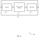
- FIG. 4 shows a block diagram 400 of a wireless device 405 in accordance with various aspects of the present disclosure.
- Wireless device 405 may be an example of aspects of a UE 115 as described herein.
- Wireless device 405 may include receiver 410, communications manager 415, and transmitter 420.
- Wireless device 405 may also include a processor. Each of these components may be in communication with one another (e.g., via one or more buses).
- Receiver 410 may receive information such as packets, user data, or control information associated with various information channels (e.g., control channels, data channels, and information related to transmit power and frequency hopping configurations for control information transmissions, etc.). Information may be passed on to other components of the device.
- the receiver 410 may be an example of aspects of the transceiver 635 described with reference to FIG. 6 .
- the receiver 410 may utilize a single antenna or a set of antennas.
- Communications manager 415 may be an example of aspects of the communications manager 615 described with reference to FIG. 6 .
- Communications manager 415 and/or at least some of its various sub-components may be implemented in hardware, software executed by a processor, firmware, or any combination thereof. If implemented in software executed by a processor, the functions of the communications manager 415 and/or at least some of its various sub-components may be executed by a general-purpose processor, a digital signal processor (DSP), an application-specific integrated circuit (ASIC), a field-programmable gate array (FPGA) or other programmable logic device, discrete gate or transistor logic, discrete hardware components, or any combination thereof designed to perform the functions described in the present disclosure.
- DSP digital signal processor
- ASIC application-specific integrated circuit
- FPGA field-programmable gate array
- the communications manager 415 and/or at least some of its various sub-components may be physically located at various positions, including being distributed such that portions of functions are implemented at different physical locations by one or more physical devices.
- communications manager 415 and/or at least some of its various sub-components may be a separate and distinct component in accordance with various aspects of the present disclosure.
- communications manager 415 and/or at least some of its various sub-components may be combined with one or more other hardware components, including but not limited to an I/O component, a transceiver, a network server, another computing device, one or more other components described in the present disclosure, or a combination thereof in accordance with various aspects of the present disclosure.
- Communications manager 415 may identify a control region of a TTI allocated for uplink communication, determine a length of the TTI allocated for uplink communication, and adjust a transmit power for transmitting uplink control information in the control region of the TTI based on the length of the TTI.
- the communications manager 415 may also identify a control region of a TTI allocated for uplink communication, identify a frequency hopping pattern for transmitting uplink control information in the control region of the TTI based on whether a portion of the TTI is allocated for an SRS transmission, and transmit the uplink control information in the control region of the TTI based on the identified frequency hopping pattern.
- Transmitter 420 may transmit signals generated by other components of the device.
- the transmitter 420 may be collocated with a receiver 410 in a transceiver module.
- the transmitter 420 may be an example of aspects of the transceiver 635 described with reference to FIG. 6 .
- the transmitter 420 may utilize a single antenna or a set of antennas.
- transmitter 420 may transmit the uplink control information in the control region of the TTI using the adjusted transmit power.
- FIG. 5 shows a block diagram 500 of a wireless device 505 in accordance with various aspects of the present disclosure.
- Wireless device 505 may be an example of aspects of a wireless device 405 or a UE 115 as described with reference to FIG. 4 .
- Wireless device 505 may include receiver 510, communications manager 515, and transmitter 520.
- Wireless device 505 may also include a processor. Each of these components may be in communication with one another (e.g., via one or more buses).
- Receiver 510 may receive information such as packets, user data, or control information associated with various information channels (e.g., control channels, data channels, and information related to transmit power and frequency hopping configurations for control information transmissions, etc.). Information may be passed on to other components of the device.
- the receiver 510 may be an example of aspects of the transceiver 635 described with reference to FIG. 6 .
- the receiver 510 may utilize a single antenna or a set of antennas.
- Communications manager 515 may be an example of aspects of the communications manager 615 described with reference to FIG. 6 .
- Communications manager 515 may include control region identifier 525, TTI length determiner 530, transmit power manager 535, SRS manager 540, and frequency hopping manager 545.
- Control region identifier 525 may identify a control region of a TTI allocated for uplink communication.
- the TTI includes three (3) symbols.
- the control region spans one symbol of the TTI.
- the length of the TTI allocated for uplink communication is determined based on an index of the TTI or a type of service associated with the TTI.
- TTI length determiner 530 may determine a length of the TTI allocated for uplink communication.
- Transmit power manager 535 may adjust a transmit power for transmitting uplink control information in the control region of the TTI based on the length of the TTI. In some aspects, transmit power manager 535 may use a first transmit power for transmitting the uplink control information during a first symbol of the TTI and use a second transmit power for transmitting the uplink control information during a second symbol of the TTI, where the first transmit power and the second transmit power are the same. In some aspects, transmit power manager 535 may receive an indication of the transmit power for transmitting uplink control information during each symbol of the TTI, where the first transmit power and the second transmit power are adjusted based on the indication. In some aspects, the indication includes a power offset parameter.
- transmit power manager 535 may use a first transmit power for transmitting the uplink control information during a first symbol of the TTI, use a second transmit power for transmitting the uplink control information during a second symbol of the TTI, and use a third transmit power for transmitting the uplink control information during a third symbol of the TTI, where each of the first transmit power, the second transmit power, and the third transmit power includes a fraction (e.g., one third (1/3)) of the adjusted transmit power for transmitting the uplink control information during the TTI.
- transmit power manager 535 may receive an indication of the transmit power for transmitting uplink control information during each symbol of the TTI, where the first transmit power, the second transmit power, and the third transmit power are adjusted based on the indication.
- the indication includes a power offset parameter.
- the adjusted transmit power includes a same transmit power used for transmitting uplink control information during a TTI including two symbols. In some aspects, adjusting the transmit power includes using a same transmit power for transmitting uplink control information during each symbol of the TTI. In some aspects, the adjusted transmit power is a same transmit power used for transmitting uplink control information during each symbol of a TTI including two symbols. In some aspects, the adjusted transmit power is greater than a transmit power used for transmitting uplink control information during each symbol of a TTI including two symbols. In some aspects, transmit power manager 535 may receive an indication of the transmit power for transmitting uplink control information during the TTI, where the transmit power is adjusted based on the indication. In some aspects, the indication includes a power offset parameter.
- SRS manager 540 may determine that one symbol of the TTI is allocated for a SRS transmission or determine that none of the symbols of the TTI are allocated for a SRS transmission. In some aspects, SRS manager 540 may determine whether a portion of the TTI is allocated for a SRS transmission. In some aspects, one symbol of the TTI is allocated for the SRS transmission and the TTI includes three (3) symbols.
- Frequency hopping manager 545 may identify a frequency hopping pattern for transmitting uplink control information in the control region of the TTI based on whether a portion of the TTI is allocated for an SRS transmission. In some aspects, which however do not fall under the scope of the present invention, frequency hopping manager 545 may transmit the uplink control information in the control region of the TTI based on the identified frequency hopping pattern. In some aspects, which however do not fall under the scope of the present invention, transmitting the uplink control information based on the identified frequency hopping pattern includes transmitting uplink control information on a first frequency region of a system bandwidth during a first symbol of the TTI, and transmitting uplink control information on a second frequency region of the system bandwidth during a second symbol of the TTI.
- Transmitter 520 may transmit signals generated by other components of the device.
- the transmitter 520 may be collocated with a receiver 510 in a transceiver module.
- the transmitter 520 may be an example of aspects of the transceiver 635 described with reference to FIG. 6 .
- the transmitter 520 may utilize a single antenna or a set of antennas.
- FIG. 6 shows a diagram of a system 600 including a device 605 in accordance with various aspects of the present disclosure.
- Device 605 may be an example of or include the components of wireless device 405, wireless device 505, or a UE 115 as described above, e.g., with reference to FIGs. 4 and 5 .
- Device 605 may include components for bi-directional voice and data communications including components for transmitting and receiving communications, including communications manager 615, processor 620, memory 625, software 630, transceiver 635, antenna 640, and I/O controller 645. These components may be in electronic communication via one or more buses (e.g., bus 610).
- Device 605 may communicate wirelessly with one or more base stations 105.
- Processor 620 may include an intelligent hardware device, (e.g., a general-purpose processor, a DSP, a central processing unit (CPU), a microcontroller, an ASIC, an FPGA, a programmable logic device, a discrete gate or transistor logic component, a discrete hardware component, or any combination thereof).
- processor 620 may be configured to operate a memory array using a memory controller.
- a memory controller may be integrated into processor 620.
- Processor 620 may be configured to execute computer-readable instructions stored in a memory to perform various functions (e.g., functions or tasks supporting transmit power and frequency hopping configurations for control information transmissions).
- Memory 625 may include random access memory (RAM) and read only memory (ROM).
- the memory 625 may store computer-readable, computer-executable software 630 including instructions that, when executed, cause the processor to perform various functions described herein.
- the memory 625 may contain, among other things, a basic input/output system (BIOS) which may control basic hardware or software operation such as the interaction with peripheral components or devices.
- BIOS basic input/output system
- Software 630 may include code to implement aspects of the present disclosure, including code to support transmit power and frequency hopping configurations for control information transmissions.
- Software 630 may be stored in a non-transitory computer-readable medium such as system memory or other memory.
- the software 630 may not be directly executable by the processor but may cause a computer (e.g., when compiled and executed) to perform functions described herein.
- Transceiver 635 may communicate bi-directionally, via one or more antennas, wired, or wireless links as described above.
- the transceiver 635 may represent a wireless transceiver and may communicate bi-directionally with another wireless transceiver.
- the transceiver 635 may also include a modem to modulate the packets and provide the modulated packets to the antennas for transmission, and to demodulate packets received from the antennas.
- the wireless device may include a single antenna 640. However, in some aspects the device may have more than one antenna 640, which may be capable of concurrently transmitting or receiving multiple wireless transmissions.
- I/O controller 645 may manage input and output signals for device 605. I/O controller 645 may also manage peripherals not integrated into device 605. In some aspects, I/O controller 645 may represent a physical connection or port to an external peripheral. In some aspects, I/O controller 645 may utilize an operating system such as iOS ® , ANDROID ® , MS-DOS ® , MS-WINDOWS ® , OS/2 ® , UNIX ® , LINUX ® , or another known operating system. In other aspects, I/O controller 645 may represent or interact with a modem, a keyboard, a mouse, a touchscreen, or a similar device. In some aspects, I/O controller 645 may be implemented as part of a processor. In some aspects, a user may interact with device 605 via I/O controller 645 or via hardware components controlled by I/O controller 645.
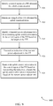
- FIG. 7 shows a flowchart illustrating a method 700 in accordance with various aspects of the present disclosure.
- the operations of method 700 may be implemented by a UE 115 or its components as described herein.
- the operations of method 700 may be performed by a communications manager as described with reference to FIGs. 4 through 6 .
- a UE 115 may execute a set of codes to control the functional elements of the device to perform the functions described below. Additionally, the UE 115 may perform aspects of the functions described below using special-purpose hardware.
- the UE 115 identifies a control region of a TTI allocated for uplink communication.
- the operations of block 705 may be performed according to the methods described herein. In certain examples, aspects of the operations of block 705 may be performed by a control region identifier as described with reference to FIGs. 4 through 6 .
- the UE 115 determines a length of the TTI allocated for uplink communication.
- the operations of block 710 may be performed according to the methods described herein. In certain examples, aspects of the operations of block 710 may be performed by a TTI length determiner as described with reference to FIGs. 4 through 6 .
- the UE 115 adjusts a transmit power for transmitting uplink control information in the control region of the TTI based at least in part on the length of the TTI.
- the operations of block 715 may be performed according to the methods described herein. In certain examples, aspects of the operations of block 715 may be performed by a transmit power manager as described with reference to FIGs. 4 through 6 .
- the UE 115 transmits the uplink control information in the control region of the TTI using the adjusted transmit power.
- the operations of block 720 may be performed according to the methods described herein. In certain examples, aspects of the operations of block 720 may be performed by a transmitter as described with reference to FIGs. 4 through 6 .
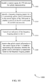
- FIG. 8 shows a flowchart illustrating a method 800 in accordance with various aspects of the present disclosure, which however do not fall under the scope of the present invention.
- the operations of method 800 may be implemented by a UE 115 or its components as described herein.
- the operations of method 800 may be performed by a communications manager as described with reference to FIGs. 4 through 6 .
- a UE 115 may execute a set of codes to control the functional elements of the device to perform the functions described below. Additionally, the UE 115 may perform aspects of the functions described below using special-purpose hardware.
- the UE 115 may identify a control region of a TTI allocated for uplink communication.
- the operations of block 805 may be performed according to the methods described herein. In certain examples, aspects of the operations of block 805 may be performed by a control region identifier as described with reference to FIGs. 4 through 6 .
- the UE 115 may identify a frequency hopping pattern for transmitting uplink control information in the control region of the TTI based at least in part on whether a portion of the TTI is allocated for a SRS transmission.
- the operations of block 810 may be performed according to the methods described herein. In certain examples, aspects of the operations of block 810 may be performed by a frequency hopping manager as described with reference to FIGs. 4 through 6 .
- the UE 115 may transmit the uplink control information in the control region of the TTI based at least in part on the identified frequency hopping pattern.
- the operations of block 815 may be performed according to the methods described herein. In certain examples, aspects of the operations of block 815 may be performed by a frequency hopping manager as described with reference to FIGs. 4 through 6 .
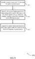
- FIG. 9 shows a flowchart illustrating a method 900 in accordance with various aspects of the present disclosure.
- the operations of method 900 may be implemented by a base station 105 or its components as described herein.
- a base station 105 may execute a set of codes to control the functional elements of the device to perform the functions described below. Additionally, the base station 105 may perform aspects of the functions described below using special-purpose hardware.
- the base station 105 identifies a control region of a TTI allocated for uplink communication.
- the base station 105 determines a length of the TTI allocated for uplink communication.
- the base station 105 identifies a transmit power adjustment for a UE 115 transmitting uplink control information in the control region of the TTI based at least in part on the length of the TTI.
- the base station 105 may transmit an indication of the transmit power adjustment to the UE 115.
- the base station 105 receives the uplink control information in the control region of the TTI based at least in part on transmitting the indication, where the uplink control information is transmitted based at least in part on the transmit power adjustment.
- the operations of blocks 905, 910, 915, 920, and 925 may be performed according to the methods described herein.
- FIG. 10 shows a flowchart illustrating a method 1000 in accordance with various aspects of the present disclosure, which however do not fall under the scope of the present invention.
- the operations of method 1000 may be implemented by a base station 105 or its components as described herein.
- a base station 105 may execute a set of codes to control the functional elements of the device to perform the functions described below. Additionally, the base station 105 may perform aspects of the functions described below using special-purpose hardware.
- the base station 105 may identify a control region of a TTI allocated for uplink communication.
- the base station 105 may identify a frequency hopping pattern for a UE transmitting uplink control information in the control region of the TTI based at least in part on whether a portion of the TTI is allocated for an SRS transmission.
- the base station 105 may transmit an indication of the frequency hopping pattern to the UE.
- the base station 105 may receive the uplink control information in the control region of the TTI based at least in part on transmitting the indication, where the uplink control information is transmitted based at least in part on the frequency hopping pattern.
- the operations of blocks 1005, 1010, 1015, 1020, and 1025 may be performed according to the methods described herein.
- CDMA code division multiple access
- TDMA time division multiple access
- FDMA frequency division multiple access
- OFDMA orthogonal frequency division multiple access
- SC-FDMA single carrier frequency division multiple access
- CDMA2000 covers IS-2000, IS-95, and IS-856 standards.
- IS-2000 Releases may be commonly referred to as CDMA2000 IX, IX, etc.
- IS-856 (TIA-856) is commonly referred to as CDMA2000 1xEV-DO, High Rate Packet Data (HRPD), etc.
- UTRA includes Wideband CDMA (WCDMA) and other variants of CDMA.
- WCDMA Wideband CDMA
- a TDMA system may implement a radio technology such as Global System for Mobile Communications (GSM).
- GSM Global System for Mobile Communications
- An OFDMA system may implement a radio technology such as Ultra Mobile Broadband (UMB), Evolved UTRA (E-UTRA), Institute of Electrical and Electronics Engineers (IEEE) 802.11 (Wi-Fi), IEEE 802.16 (WiMAX), IEEE 802.20, Flash-OFDM, etc.
- UMB Ultra Mobile Broadband
- E-UTRA Evolved UTRA
- IEEE Institute of Electrical and Electronics Engineers
- Wi-Fi Wi-Fi
- WiMAX IEEE 802.16
- IEEE 802.20 Flash-OFDM
- UMB Ultra Mobile Broadband
- E-UTRA Evolved UTRA
- IEEE 802.11 Wi-Fi
- WiMAX IEEE 802.16
- Flash-OFDM Flash-OFDM
- UTRA and E-UTRA are part of Universal Mobile Telecommunications System (UMTS).
- LTE and LTE-A are releases of UMTS that use E-UTRA.
- LTE or NR may be described for purposes of example, and LTE or NR terminology may be used in much of the description, the techniques described herein are applicable beyond LTE or NR applications.
- the term evolved node B may be generally used to describe the base stations.
- the wireless communications system or systems described herein may include a heterogeneous LTE/LTE-A or NR network in which different types of eNBs provide coverage for various geographical regions.
- each eNB, next generation NodeB (gNB), or base station may provide communication coverage for a macro cell, a small cell, or other types of cell.
- the term "cell” may be used to describe a base station, a carrier or component carrier associated with a base station, or a coverage area (e.g., sector, etc.) of a carrier or base station, depending on context.
- Base stations may include or may be referred to by those skilled in the art as a base transceiver station, a radio base station, an access point, a radio transceiver, a NodeB, eNodeB (eNB), gNB, Home NodeB, a Home eNodeB, or some other suitable terminology.
- the geographic coverage area for a base station may be divided into sectors making up only a portion of the coverage area.
- the wireless communications system or systems described herein may include base stations of different types (e.g., macro or small cell base stations).
- the UEs described herein may be able to communicate with various types of base stations and network equipment including macro eNBs, small cell eNBs, gNBs, relay base stations, and the like. There may be overlapping geographic coverage areas for different technologies.
- a macro cell generally covers a relatively large geographic area (e.g., several kilometers in radius) and may allow unrestricted access by UEs with service subscriptions with the network provider.
- a small cell is a lower-powered base station, as compared with a macro cell, that may operate in the same or different (e.g., licensed, unlicensed, etc.) frequency bands as macro cells.
- Small cells may include pico cells, femto cells, and micro cells according to various examples.
- a pico cell for example, may cover a small geographic area and may allow unrestricted access by UEs with service subscriptions with the network provider.
- a femto cell may also cover a small geographic area (e.g., a home) and may provide restricted access by UEs having an association with the femto cell (e.g., UEs in a closed subscriber group (CSG), UEs for users in the home, and the like).
- An eNB for a macro cell may be referred to as a macro eNB.
- An eNB for a small cell may be referred to as a small cell eNB, a pico eNB, a femto eNB, or a home eNB.
- An eNB may support one or multiple (e.g., two, three, four, and the like) cells (e.g., component carriers).
- the wireless communications system or systems described herein may support synchronous or asynchronous operation.
- the base stations may have similar frame timing, and transmissions from different base stations may be approximately aligned in time.
- the base stations may have different frame timing, and transmissions from different base stations may not be aligned in time.
- the techniques described herein may be used for either synchronous or asynchronous operations.
- Information and signals described herein may be represented using any of a variety of different technologies and techniques.
- data, instructions, commands, information, signals, bits, symbols, and chips that may be referenced throughout the above description may be represented by voltages, currents, electromagnetic waves, magnetic fields or particles, optical fields or particles, or any combination thereof.
- a general-purpose processor may be a microprocessor, but in the alternative, the processor may be any conventional processor, controller, microcontroller, or state machine.
- a processor may also be implemented as a combination of computing devices (e.g., a combination of a DSP and a microprocessor, multiple microprocessors, one or more microprocessors in conjunction with a DSP core, or any other such configuration).
- the functions described herein may be implemented in hardware, software executed by a processor, firmware, or any combination thereof. If implemented in software executed by a processor, the functions may be stored on or transmitted over as one or more instructions or code on a computer-readable medium. Other examples and implementations are within the scope of the disclosure and appended claims. For example, due to the nature of software, functions described above can be implemented using software executed by a processor, hardware, firmware, hardwiring, or combinations of any of these. Features implementing functions may also be physically located at various positions, including being distributed such that portions of functions are implemented at different physical locations.
- Computer-readable media includes both non-transitory computer storage media and communication media including any medium that facilitates transfer of a computer program from one place to another.
- a non-transitory storage medium may be any available medium that can be accessed by a general purpose or special purpose computer.
- non-transitory computer-readable media may comprise RAM, ROM, electrically erasable programmable read only memory (EEPROM), compact disk (CD) ROM or other optical disk storage, magnetic disk storage or other magnetic storage devices, or any other non-transitory medium that can be used to carry or store desired program code means in the form of instructions or data structures and that can be accessed by a general-purpose or special-purpose computer, or a general-purpose or special-purpose processor.
- RAM random access memory
- ROM read only memory
- EEPROM electrically erasable programmable read only memory
- CD compact disk
- magnetic disk storage or other magnetic storage devices or any other non-transitory medium that can be used to carry or store desired program code means in the form of instructions or data structures
- any connection is properly termed a computer-readable medium.
- the software is transmitted from a website, server, or other remote source using a coaxial cable, fiber optic cable, twisted pair, digital subscriber line (DSL), or wireless technologies such as infrared, radio, and microwave
- the coaxial cable, fiber optic cable, twisted pair, DSL, or wireless technologies such as infrared, radio, and microwave are included in the definition of medium.
- Disk and disc include CD, laser disc, optical disc, digital versatile disc (DVD), floppy disk and Blu-ray disc where disks usually reproduce data magnetically, while discs reproduce data optically with lasers. Combinations of the above are also included within the scope of computer-readable media.
Landscapes
- Engineering & Computer Science (AREA)
- Signal Processing (AREA)
- Computer Networks & Wireless Communication (AREA)
- Power Engineering (AREA)
- Quality & Reliability (AREA)
- Mobile Radio Communication Systems (AREA)
Claims (15)
- Ein Verfahren für Drahtloskommunikation in einem System, das mehrere Sendezeitintervall- bzw. TTI-Längen (TTI = transmission time interval) unterstützt, das Folgendes aufweist:Identifizieren (705) einer Steuerregion eines TTI, das für Uplink- bzw. Aufwärtsstreckenkommunikation zugeteilt ist;Bestimmen (710) einer Länge des TTI, das für Aufwärtsstreckenkommunikation zugeteilt ist;Anpassen (715) einer Sendeleistung zum Senden von Aufwärtsstreckensteuerinformation in der Steuerregion des TTI basierend wenigstens teilweise auf der Länge des TTI, so dass eine Sendeleistung, die zum Senden von Aufwärtsstreckensteuerinformation in jedem Symbol des TTI genutzt wird, die gleiche ist wie eine Sendeleistung, die zum Senden von Aufwärtsstreckensteuerinformation in jedem Symbol eines anderen TTI genutzt wird, das eine unterschiedliche Länge hat; undSenden (720) der Aufwärtsstreckensteuerinformation in der Steuerregion des TTI unter Nutzung der angepassten Sendeleistung.
- Verfahren nach Anspruch 1, wobei das Anpassen der Sendeleistung Folgendes aufweist:
Nutzen einer gleichen Sendeleistung zum Senden von Aufwärtsstreckensteuerinformation während jedes Symbols des TTI. - Verfahren nach Anspruch 1, wobei das TTI drei Symbole aufweist.
- Verfahren nach Anspruch 3, wobei die angepasste Sendeleistung, die zum Senden von Aufwärtsstreckensteuerinformation während des TTI genutzt wird, das drei Symbole aufweist, eine gleiche Sendeleistung aufweist, die zum Senden von Aufwärtsstreckensteuerinformation während eines TTI genutzt wird, das zwei Symbole aufweist.
- Verfahren nach Anspruch 3, das weiter Folgendes aufweist:
Bestimmen, dass ein Symbol des TTI für eine Sondierungsreferenzsignal- bzw. SRS-Sendung (SRS = sounding reference signal) zugeteilt ist. - Verfahren nach Anspruch 5, das weiter Folgendes aufweist:Nutzen einer ersten Sendeleistung zum Senden der Aufwärtsstreckensteuerinformation während eines ersten Symbols des TTI und Nutzen einer zweiten Sendeleistung zum Senden der Aufwärtsstreckensteuerinformation während eines zweiten Symbols des TTI,wobei die erste Sendeleistung und die zweite Sendeleistung die gleiche sind.
- Verfahren nach Anspruch 6, das weiter Folgendes aufweist:
Empfangen einer Anzeige der Sendeleistung zum Senden von Aufwärtsstreckensteuerinformation während jedes Symbols des TTI, wobei die erste Sendeleistung und die zweite Sendeleistung basierend wenigstens teilweise auf der Anzeige angepasst werden. - Verfahren nach Anspruch 7, wobei die Anzeige einen Leistungsversatzparameter aufweist.
- Verfahren nach Anspruch 3, das weiter Folgendes aufweist:
Bestimmen, dass keines der Symbole des TTI für eine Sondierungsreferenzsignal- bzw. SRS-Sendung (SRS = sounding reference signal) zugeteilt ist. - Verfahren nach Anspruch 9, das weiter Folgendes aufweist:Nutzen einer ersten Sendeleistung zum Senden der Aufwärtsstreckensteuerinformation während eines ersten Symbols des TTI, Nutzen einer zweiten Sendeleistung zum Senden der Aufwärtsstreckensteuerinformation während eines zweiten Symbols des TTI und Nutzen einer dritten Sendeleistung zum Senden der Aufwärtsstreckensteuerinformation während eines dritten Symbols des TTI,wobei jedes von der ersten Sendeleistung, der zweiten Sendeleistung und der dritten Sendeleistung einen Bruchteil der angepassten Sendeleistung zum Senden der Aufwärtsstreckensteuerinformation während des TTI aufweist.
- Verfahren nach Anspruch 10, das weiter Folgendes aufweist:
Empfangen einer Anzeige der Sendeleistung zum Senden von Aufwärtsstreckensteuerinformation während jedes Symbols des TTI, wobei die erste Sendeleistung, die zweite Sendeleistung und die dritte Sendeleistung basierend wenigstens teilweise auf der Anzeige angepasst werden. - Verfahren nach Anspruch 1, wobei die Steuerregion ein Symbol des TTI überspannt.
- Verfahren nach Anspruch 1, wobei die Länge des TTI, das für Aufwärtsstreckenkommunikation zugeteilt ist, basierend wenigstens teilweise auf einem Index des TTI oder einem Typ von Dienst, der mit dem TTI assoziiert ist, bestimmt wird.
- Eine Vorrichtung für Drahtloskommunikation in einem System, das mehrere Sendezeitintervall- bzw. TTI-Längen unterstützt, die Mittel aufweist zum Ausführen aller Verfahrensschritte nach einem der Ansprüche 1 bis 13.
- Ein nicht transitorisches computerlesbares Medium, das Code für Drahtloskommunikation in einem System speichert, das mehrere Sendezeitintervall- bzw. TTI-Längen (TTI = transmission time interval) unterstützt, wobei der Code, wenn er durch einen Prozessor ausgeführt wird, das Verfahren nach einem der Ansprüche 1 bis 13 durchführt.
Applications Claiming Priority (3)
| Application Number | Priority Date | Filing Date | Title |
|---|---|---|---|
| US201762511921P | 2017-05-26 | 2017-05-26 | |
| US15/988,144 US10931484B2 (en) | 2017-05-26 | 2018-05-24 | Transmit power and frequency hopping configurations for control information transmissions |
| PCT/US2018/034732 WO2018218200A1 (en) | 2017-05-26 | 2018-05-25 | Transmit power and frequency hopping configurations for control information transmissions |
Publications (2)
| Publication Number | Publication Date |
|---|---|
| EP3632166A1 EP3632166A1 (de) | 2020-04-08 |
| EP3632166B1 true EP3632166B1 (de) | 2022-01-12 |
Family
ID=62683439
Family Applications (1)
| Application Number | Title | Priority Date | Filing Date |
|---|---|---|---|
| EP18732546.9A Active EP3632166B1 (de) | 2017-05-26 | 2018-05-25 | Sendeleistungs- und frequenzsprungkonfigurationen für übertragungen von steuerungsinformationen |
Country Status (10)
| Country | Link |
|---|---|
| US (1) | US10931484B2 (de) |
| EP (1) | EP3632166B1 (de) |
| JP (1) | JP7100671B2 (de) |
| KR (1) | KR20200012906A (de) |
| CN (2) | CN114245451B (de) |
| BR (1) | BR112019024575A2 (de) |
| CA (1) | CA3059792A1 (de) |
| ES (1) | ES2905593T3 (de) |
| TW (1) | TW201902269A (de) |
| WO (1) | WO2018218200A1 (de) |
Families Citing this family (9)
| Publication number | Priority date | Publication date | Assignee | Title |
|---|---|---|---|---|
| US10492151B2 (en) * | 2017-06-09 | 2019-11-26 | Qualcomm Incorporated | Power control in new radio systems |
| KR102379822B1 (ko) * | 2017-06-15 | 2022-03-30 | 삼성전자 주식회사 | 빔포밍 시스템에서 단말의 송신 전력 제어 방법 및 장치 |
| WO2018230901A1 (ko) | 2017-06-15 | 2018-12-20 | 삼성전자 주식회사 | 빔포밍 시스템에서 단말의 송신 전력 제어 방법 및 장치 |
| WO2019031907A1 (ko) * | 2017-08-10 | 2019-02-14 | 엘지전자 주식회사 | 무선 통신 시스템에서 단말이 상향링크 신호를 전송하는 방법 및 이를 지원하는 장치 |
| ES2959283T3 (es) * | 2017-09-15 | 2024-02-22 | Ntt Docomo Inc | Terminal de usuario y método de comunicación por radio |
| US10764833B2 (en) * | 2018-04-16 | 2020-09-01 | Qualcomm Incorporated | Uplink preemption or dynamic power control for mobile broadband and low latency communication multiplexing |
| CN111669205B (zh) * | 2019-03-07 | 2021-08-17 | 荣耀终端有限公司 | 一种信道测量方法及设备 |
| US11617139B2 (en) | 2019-08-27 | 2023-03-28 | Qualcomm Incorporated | Power control for repeated uplink transmissions |
| WO2021142655A1 (en) * | 2020-01-15 | 2021-07-22 | Lenovo (Beijing) Limited | Determining a length of sounding reference signal symbols |
Family Cites Families (14)
| Publication number | Priority date | Publication date | Assignee | Title |
|---|---|---|---|---|
| EP2600581A4 (de) * | 2010-07-26 | 2017-09-27 | LG Electronics Inc. | Verfahren und vorrichtung zur übertragung von klangreferenzsignalen und erweiterten uplink-steuerinformationen in einem drahtlosen kommunikationssystem |
| US9455772B2 (en) * | 2013-06-28 | 2016-09-27 | Huawei Technologies Co., Ltd. | System and method for network uplink measurement based operation using UE centric sounding |
| JP6789211B2 (ja) | 2014-09-08 | 2020-11-25 | インターデイジタル パテント ホールディングス インコーポレイテッド | 異なる送信時間間隔(tti)持続時間により動作するシステムおよび方法 |
| US9980257B2 (en) * | 2014-09-26 | 2018-05-22 | Qualcomm Incorporated | Ultra-low latency LTE reference signal transmission |
| US9749970B2 (en) | 2015-02-27 | 2017-08-29 | Qualcomm Incorporated | Power control and power headroom for component carrier |
| US10085255B2 (en) | 2015-09-02 | 2018-09-25 | Qualcomm Incorporated | Physical uplink control channel for low latency downlink communications |
| US11419110B2 (en) | 2015-11-03 | 2022-08-16 | Apple Inc. | Short transmission time interval (TTI) |
| US10271316B2 (en) | 2016-03-21 | 2019-04-23 | Sharp Kabushiki Kaisha | User equipments, base stations and methods |
| US10542503B2 (en) | 2016-04-01 | 2020-01-21 | Motorola Mobility Llc | Method and apparatus for scheduling uplink transmissions with reduced latency |
| WO2017171516A1 (ko) * | 2016-04-01 | 2017-10-05 | 엘지전자 주식회사 | 무선 통신 시스템에서 상향링크 제어 정보의 전송 또는 수신 방법 및 이를 위한 장치 |
| ES2824475T3 (es) | 2016-05-12 | 2021-05-12 | Asustek Comp Inc | Transmisión de enlace ascendente en intervalos de tiempo de transmisión acortados en un sistema de comunicación inalámbrico |
| EP3456126B1 (de) | 2016-05-13 | 2022-03-02 | Telefonaktiebolaget LM Ericsson (publ) | Konfiguration von uplink-übertragungen für eine drahtlose vorrichtung |
| CN106131963A (zh) * | 2016-06-12 | 2016-11-16 | 珠海市魅族科技有限公司 | 资源配置方法及装置、基站 |
| EP3520504B1 (de) * | 2016-09-30 | 2023-04-05 | Telefonaktiebolaget LM Ericsson (PUBL) | Systeme und verfahren zur leistungsregelung eines physikalischen kanals in einem kommunikationssystem |
-
2018
- 2018-05-24 US US15/988,144 patent/US10931484B2/en active Active
- 2018-05-25 CN CN202210105351.3A patent/CN114245451B/zh active Active
- 2018-05-25 KR KR1020197037695A patent/KR20200012906A/ko not_active Application Discontinuation
- 2018-05-25 BR BR112019024575A patent/BR112019024575A2/pt unknown
- 2018-05-25 WO PCT/US2018/034732 patent/WO2018218200A1/en active Application Filing
- 2018-05-25 CN CN201880033350.4A patent/CN110710279B/zh active Active
- 2018-05-25 CA CA3059792A patent/CA3059792A1/en active Pending
- 2018-05-25 ES ES18732546T patent/ES2905593T3/es active Active
- 2018-05-25 JP JP2019564871A patent/JP7100671B2/ja active Active
- 2018-05-25 TW TW107117915A patent/TW201902269A/zh unknown
- 2018-05-25 EP EP18732546.9A patent/EP3632166B1/de active Active
Also Published As
| Publication number | Publication date |
|---|---|
| BR112019024575A2 (pt) | 2020-06-09 |
| US10931484B2 (en) | 2021-02-23 |
| EP3632166A1 (de) | 2020-04-08 |
| CN114245451B (zh) | 2024-01-23 |
| WO2018218200A1 (en) | 2018-11-29 |
| CA3059792A1 (en) | 2018-11-29 |
| ES2905593T3 (es) | 2022-04-11 |
| KR20200012906A (ko) | 2020-02-05 |
| CN110710279A (zh) | 2020-01-17 |
| JP7100671B2 (ja) | 2022-07-13 |
| JP2020522168A (ja) | 2020-07-27 |
| US20180343148A1 (en) | 2018-11-29 |
| TW201902269A (zh) | 2019-01-01 |
| CN114245451A (zh) | 2022-03-25 |
| CN110710279B (zh) | 2022-06-28 |
Similar Documents
| Publication | Publication Date | Title |
|---|---|---|
| EP3632166B1 (de) | Sendeleistungs- und frequenzsprungkonfigurationen für übertragungen von steuerungsinformationen | |
| US11497007B2 (en) | Sounding reference signal configuration and transport block size scaling in low latency systems | |
| EP3535913B1 (de) | Dynamische referenzsignalkonfiguration für drahtlose kommunikation mit verkürzten übertragungszeitintervallen | |
| EP3539245B1 (de) | Referenzsignalmuster und gemeinsame nutzung von pilotsignalen für drahtloskommunikation mit verkürzten übertragungszeitintervallen | |
| EP3613166B1 (de) | Physikalische downlink-steuerkanalstruktur in systemen mit niedriger latenz | |
| US11412487B2 (en) | Uplink channel multiplexing and waveform selection | |
| US10448380B2 (en) | Split symbol control for aligned numerology | |
| CN109792351B (zh) | 参考信号设计的方法、装置和计算机可读介质 | |
| EP3620002B1 (de) | Vorwärtskompatibilität in new-radio-systemen |
Legal Events
| Date | Code | Title | Description |
|---|---|---|---|
| STAA | Information on the status of an ep patent application or granted ep patent |
Free format text: STATUS: UNKNOWN |
|
| STAA | Information on the status of an ep patent application or granted ep patent |
Free format text: STATUS: THE INTERNATIONAL PUBLICATION HAS BEEN MADE |
|
| PUAI | Public reference made under article 153(3) epc to a published international application that has entered the european phase |
Free format text: ORIGINAL CODE: 0009012 |
|
| STAA | Information on the status of an ep patent application or granted ep patent |
Free format text: STATUS: REQUEST FOR EXAMINATION WAS MADE |
|
| 17P | Request for examination filed |
Effective date: 20191028 |
|
| AK | Designated contracting states |
Kind code of ref document: A1 Designated state(s): AL AT BE BG CH CY CZ DE DK EE ES FI FR GB GR HR HU IE IS IT LI LT LU LV MC MK MT NL NO PL PT RO RS SE SI SK SM TR |
|
| AX | Request for extension of the european patent |
Extension state: BA ME |
|
| DAV | Request for validation of the european patent (deleted) | ||
| DAX | Request for extension of the european patent (deleted) | ||
| STAA | Information on the status of an ep patent application or granted ep patent |
Free format text: STATUS: EXAMINATION IS IN PROGRESS |
|
| STAA | Information on the status of an ep patent application or granted ep patent |
Free format text: STATUS: EXAMINATION IS IN PROGRESS |
|
| 17Q | First examination report despatched |
Effective date: 20201120 |
|
| GRAP | Despatch of communication of intention to grant a patent |
Free format text: ORIGINAL CODE: EPIDOSNIGR1 |
|
| STAA | Information on the status of an ep patent application or granted ep patent |
Free format text: STATUS: GRANT OF PATENT IS INTENDED |
|
| INTG | Intention to grant announced |
Effective date: 20210727 |
|
| GRAS | Grant fee paid |
Free format text: ORIGINAL CODE: EPIDOSNIGR3 |
|
| GRAA | (expected) grant |
Free format text: ORIGINAL CODE: 0009210 |
|
| STAA | Information on the status of an ep patent application or granted ep patent |
Free format text: STATUS: THE PATENT HAS BEEN GRANTED |
|
| AK | Designated contracting states |
Kind code of ref document: B1 Designated state(s): AL AT BE BG CH CY CZ DE DK EE ES FI FR GB GR HR HU IE IS IT LI LT LU LV MC MK MT NL NO PL PT RO RS SE SI SK SM TR |
|
| REG | Reference to a national code |
Ref country code: GB Ref legal event code: FG4D |
|
| REG | Reference to a national code |
Ref country code: CH Ref legal event code: EP |
|
| REG | Reference to a national code |
Ref country code: DE Ref legal event code: R096 Ref document number: 602018029522 Country of ref document: DE |
|
| REG | Reference to a national code |
Ref country code: IE Ref legal event code: FG4D |
|
| REG | Reference to a national code |
Ref country code: AT Ref legal event code: REF Ref document number: 1463186 Country of ref document: AT Kind code of ref document: T Effective date: 20220215 |
|
| REG | Reference to a national code |
Ref country code: NL Ref legal event code: FP |
|
| REG | Reference to a national code |
Ref country code: SE Ref legal event code: TRGR |
|
| REG | Reference to a national code |
Ref country code: NO Ref legal event code: T2 Effective date: 20220112 |
|
| REG | Reference to a national code |
Ref country code: ES Ref legal event code: FG2A Ref document number: 2905593 Country of ref document: ES Kind code of ref document: T3 Effective date: 20220411 |
|
| REG | Reference to a national code |
Ref country code: LT Ref legal event code: MG9D |
|
| REG | Reference to a national code |
Ref country code: AT Ref legal event code: MK05 Ref document number: 1463186 Country of ref document: AT Kind code of ref document: T Effective date: 20220112 |
|
| PG25 | Lapsed in a contracting state [announced via postgrant information from national office to epo] |
Ref country code: RS Free format text: LAPSE BECAUSE OF FAILURE TO SUBMIT A TRANSLATION OF THE DESCRIPTION OR TO PAY THE FEE WITHIN THE PRESCRIBED TIME-LIMIT Effective date: 20220112 Ref country code: PT Free format text: LAPSE BECAUSE OF FAILURE TO SUBMIT A TRANSLATION OF THE DESCRIPTION OR TO PAY THE FEE WITHIN THE PRESCRIBED TIME-LIMIT Effective date: 20220512 Ref country code: LT Free format text: LAPSE BECAUSE OF FAILURE TO SUBMIT A TRANSLATION OF THE DESCRIPTION OR TO PAY THE FEE WITHIN THE PRESCRIBED TIME-LIMIT Effective date: 20220112 Ref country code: HR Free format text: LAPSE BECAUSE OF FAILURE TO SUBMIT A TRANSLATION OF THE DESCRIPTION OR TO PAY THE FEE WITHIN THE PRESCRIBED TIME-LIMIT Effective date: 20220112 Ref country code: BG Free format text: LAPSE BECAUSE OF FAILURE TO SUBMIT A TRANSLATION OF THE DESCRIPTION OR TO PAY THE FEE WITHIN THE PRESCRIBED TIME-LIMIT Effective date: 20220412 |
|
| PGFP | Annual fee paid to national office [announced via postgrant information from national office to epo] |
Ref country code: NO Payment date: 20220425 Year of fee payment: 5 Ref country code: ES Payment date: 20220609 Year of fee payment: 5 |
|
| PG25 | Lapsed in a contracting state [announced via postgrant information from national office to epo] |
Ref country code: PL Free format text: LAPSE BECAUSE OF FAILURE TO SUBMIT A TRANSLATION OF THE DESCRIPTION OR TO PAY THE FEE WITHIN THE PRESCRIBED TIME-LIMIT Effective date: 20220112 Ref country code: LV Free format text: LAPSE BECAUSE OF FAILURE TO SUBMIT A TRANSLATION OF THE DESCRIPTION OR TO PAY THE FEE WITHIN THE PRESCRIBED TIME-LIMIT Effective date: 20220112 Ref country code: GR Free format text: LAPSE BECAUSE OF FAILURE TO SUBMIT A TRANSLATION OF THE DESCRIPTION OR TO PAY THE FEE WITHIN THE PRESCRIBED TIME-LIMIT Effective date: 20220413 Ref country code: FI Free format text: LAPSE BECAUSE OF FAILURE TO SUBMIT A TRANSLATION OF THE DESCRIPTION OR TO PAY THE FEE WITHIN THE PRESCRIBED TIME-LIMIT Effective date: 20220112 Ref country code: AT Free format text: LAPSE BECAUSE OF FAILURE TO SUBMIT A TRANSLATION OF THE DESCRIPTION OR TO PAY THE FEE WITHIN THE PRESCRIBED TIME-LIMIT Effective date: 20220112 |
|
| PGFP | Annual fee paid to national office [announced via postgrant information from national office to epo] |
Ref country code: CH Payment date: 20220413 Year of fee payment: 5 |
|
| PG25 | Lapsed in a contracting state [announced via postgrant information from national office to epo] |
Ref country code: IS Free format text: LAPSE BECAUSE OF FAILURE TO SUBMIT A TRANSLATION OF THE DESCRIPTION OR TO PAY THE FEE WITHIN THE PRESCRIBED TIME-LIMIT Effective date: 20220512 |
|
| REG | Reference to a national code |
Ref country code: DE Ref legal event code: R097 Ref document number: 602018029522 Country of ref document: DE |
|
| PG25 | Lapsed in a contracting state [announced via postgrant information from national office to epo] |
Ref country code: SM Free format text: LAPSE BECAUSE OF FAILURE TO SUBMIT A TRANSLATION OF THE DESCRIPTION OR TO PAY THE FEE WITHIN THE PRESCRIBED TIME-LIMIT Effective date: 20220112 Ref country code: SK Free format text: LAPSE BECAUSE OF FAILURE TO SUBMIT A TRANSLATION OF THE DESCRIPTION OR TO PAY THE FEE WITHIN THE PRESCRIBED TIME-LIMIT Effective date: 20220112 Ref country code: RO Free format text: LAPSE BECAUSE OF FAILURE TO SUBMIT A TRANSLATION OF THE DESCRIPTION OR TO PAY THE FEE WITHIN THE PRESCRIBED TIME-LIMIT Effective date: 20220112 Ref country code: EE Free format text: LAPSE BECAUSE OF FAILURE TO SUBMIT A TRANSLATION OF THE DESCRIPTION OR TO PAY THE FEE WITHIN THE PRESCRIBED TIME-LIMIT Effective date: 20220112 Ref country code: DK Free format text: LAPSE BECAUSE OF FAILURE TO SUBMIT A TRANSLATION OF THE DESCRIPTION OR TO PAY THE FEE WITHIN THE PRESCRIBED TIME-LIMIT Effective date: 20220112 Ref country code: CZ Free format text: LAPSE BECAUSE OF FAILURE TO SUBMIT A TRANSLATION OF THE DESCRIPTION OR TO PAY THE FEE WITHIN THE PRESCRIBED TIME-LIMIT Effective date: 20220112 |
|
| PLBE | No opposition filed within time limit |
Free format text: ORIGINAL CODE: 0009261 |
|
| STAA | Information on the status of an ep patent application or granted ep patent |
Free format text: STATUS: NO OPPOSITION FILED WITHIN TIME LIMIT |
|
| PG25 | Lapsed in a contracting state [announced via postgrant information from national office to epo] |
Ref country code: AL Free format text: LAPSE BECAUSE OF FAILURE TO SUBMIT A TRANSLATION OF THE DESCRIPTION OR TO PAY THE FEE WITHIN THE PRESCRIBED TIME-LIMIT Effective date: 20220112 |
|
| 26N | No opposition filed |
Effective date: 20221013 |
|
| REG | Reference to a national code |
Ref country code: BE Ref legal event code: MM Effective date: 20220531 |
|
| PG25 | Lapsed in a contracting state [announced via postgrant information from national office to epo] |
Ref country code: MC Free format text: LAPSE BECAUSE OF FAILURE TO SUBMIT A TRANSLATION OF THE DESCRIPTION OR TO PAY THE FEE WITHIN THE PRESCRIBED TIME-LIMIT Effective date: 20220112 Ref country code: LU Free format text: LAPSE BECAUSE OF NON-PAYMENT OF DUE FEES Effective date: 20220525 |
|
| PG25 | Lapsed in a contracting state [announced via postgrant information from national office to epo] |
Ref country code: SI Free format text: LAPSE BECAUSE OF FAILURE TO SUBMIT A TRANSLATION OF THE DESCRIPTION OR TO PAY THE FEE WITHIN THE PRESCRIBED TIME-LIMIT Effective date: 20220112 |
|
| PG25 | Lapsed in a contracting state [announced via postgrant information from national office to epo] |
Ref country code: IE Free format text: LAPSE BECAUSE OF NON-PAYMENT OF DUE FEES Effective date: 20220525 |
|
| PG25 | Lapsed in a contracting state [announced via postgrant information from national office to epo] |
Ref country code: BE Free format text: LAPSE BECAUSE OF NON-PAYMENT OF DUE FEES Effective date: 20220531 |
|
| PGFP | Annual fee paid to national office [announced via postgrant information from national office to epo] |
Ref country code: SE Payment date: 20230315 Year of fee payment: 6 |
|
| PG25 | Lapsed in a contracting state [announced via postgrant information from national office to epo] |
Ref country code: IT Free format text: LAPSE BECAUSE OF FAILURE TO SUBMIT A TRANSLATION OF THE DESCRIPTION OR TO PAY THE FEE WITHIN THE PRESCRIBED TIME-LIMIT Effective date: 20220112 |
|
| PGFP | Annual fee paid to national office [announced via postgrant information from national office to epo] |
Ref country code: FR Payment date: 20230412 Year of fee payment: 6 Ref country code: DE Payment date: 20230412 Year of fee payment: 6 |
|
| PGFP | Annual fee paid to national office [announced via postgrant information from national office to epo] |
Ref country code: GB Payment date: 20230412 Year of fee payment: 6 |
|
| REG | Reference to a national code |
Ref country code: NO Ref legal event code: MMEP |
|
| REG | Reference to a national code |
Ref country code: CH Ref legal event code: PL |
|
| PG25 | Lapsed in a contracting state [announced via postgrant information from national office to epo] |
Ref country code: NO Free format text: LAPSE BECAUSE OF NON-PAYMENT OF DUE FEES Effective date: 20230531 Ref country code: LI Free format text: LAPSE BECAUSE OF NON-PAYMENT OF DUE FEES Effective date: 20230531 Ref country code: CH Free format text: LAPSE BECAUSE OF NON-PAYMENT OF DUE FEES Effective date: 20230531 |
|
| PG25 | Lapsed in a contracting state [announced via postgrant information from national office to epo] |
Ref country code: MK Free format text: LAPSE BECAUSE OF FAILURE TO SUBMIT A TRANSLATION OF THE DESCRIPTION OR TO PAY THE FEE WITHIN THE PRESCRIBED TIME-LIMIT Effective date: 20220112 Ref country code: CY Free format text: LAPSE BECAUSE OF FAILURE TO SUBMIT A TRANSLATION OF THE DESCRIPTION OR TO PAY THE FEE WITHIN THE PRESCRIBED TIME-LIMIT Effective date: 20220112 |
|
| PGFP | Annual fee paid to national office [announced via postgrant information from national office to epo] |
Ref country code: NL Payment date: 20240415 Year of fee payment: 7 |