EP3632050B1 - Convertisseur de données de bus - Google Patents
Convertisseur de données de bus Download PDFInfo
- Publication number
- EP3632050B1 EP3632050B1 EP18725828.0A EP18725828A EP3632050B1 EP 3632050 B1 EP3632050 B1 EP 3632050B1 EP 18725828 A EP18725828 A EP 18725828A EP 3632050 B1 EP3632050 B1 EP 3632050B1
- Authority
- EP
- European Patent Office
- Prior art keywords
- data
- unit
- bus
- symbols
- local bus
- Prior art date
- Legal status (The legal status is an assumption and is not a legal conclusion. Google has not performed a legal analysis and makes no representation as to the accuracy of the status listed.)
- Active
Links
- 238000000034 method Methods 0.000 claims description 156
- 230000008569 process Effects 0.000 claims description 150
- 238000013523 data management Methods 0.000 claims description 60
- 238000012546 transfer Methods 0.000 claims description 42
- 230000001419 dependent effect Effects 0.000 claims description 8
- 230000008878 coupling Effects 0.000 claims description 2
- 238000010168 coupling process Methods 0.000 claims description 2
- 238000005859 coupling reaction Methods 0.000 claims description 2
- 238000012545 processing Methods 0.000 description 22
- 101100408464 Caenorhabditis elegans plc-1 gene Proteins 0.000 description 20
- 238000004891 communication Methods 0.000 description 12
- 238000011144 upstream manufacturing Methods 0.000 description 12
- 238000006243 chemical reaction Methods 0.000 description 10
- 238000010586 diagram Methods 0.000 description 8
- 230000005540 biological transmission Effects 0.000 description 7
- 230000008859 change Effects 0.000 description 5
- 230000006870 function Effects 0.000 description 5
- 238000005259 measurement Methods 0.000 description 5
- 230000001276 controlling effect Effects 0.000 description 4
- 239000004065 semiconductor Substances 0.000 description 4
- 238000007726 management method Methods 0.000 description 3
- 230000003287 optical effect Effects 0.000 description 3
- 230000009471 action Effects 0.000 description 2
- 230000008901 benefit Effects 0.000 description 2
- 230000003139 buffering effect Effects 0.000 description 2
- 238000005516 engineering process Methods 0.000 description 2
- 230000001105 regulatory effect Effects 0.000 description 2
- 230000000717 retained effect Effects 0.000 description 2
- 238000000926 separation method Methods 0.000 description 2
- 230000001360 synchronised effect Effects 0.000 description 2
- 230000007704 transition Effects 0.000 description 2
- 238000013519 translation Methods 0.000 description 2
- 238000012800 visualization Methods 0.000 description 2
- 230000001427 coherent effect Effects 0.000 description 1
- 125000004122 cyclic group Chemical group 0.000 description 1
- 230000001934 delay Effects 0.000 description 1
- 230000003111 delayed effect Effects 0.000 description 1
- 238000013461 design Methods 0.000 description 1
- 238000011156 evaluation Methods 0.000 description 1
- 208000025697 familial rhabdoid tumor Diseases 0.000 description 1
- 238000009434 installation Methods 0.000 description 1
- 238000012423 maintenance Methods 0.000 description 1
- 239000000463 material Substances 0.000 description 1
- 238000012544 monitoring process Methods 0.000 description 1
- 238000013439 planning Methods 0.000 description 1
- 230000001902 propagating effect Effects 0.000 description 1
- 230000008707 rearrangement Effects 0.000 description 1
Images


Classifications
-
- H—ELECTRICITY
- H04—ELECTRIC COMMUNICATION TECHNIQUE
- H04L—TRANSMISSION OF DIGITAL INFORMATION, e.g. TELEGRAPHIC COMMUNICATION
- H04L12/00—Data switching networks
- H04L12/28—Data switching networks characterised by path configuration, e.g. LAN [Local Area Networks] or WAN [Wide Area Networks]
- H04L12/40—Bus networks
- H04L12/40006—Architecture of a communication node
- H04L12/40019—Details regarding a bus master
-
- H—ELECTRICITY
- H04—ELECTRIC COMMUNICATION TECHNIQUE
- H04L—TRANSMISSION OF DIGITAL INFORMATION, e.g. TELEGRAPHIC COMMUNICATION
- H04L12/00—Data switching networks
- H04L12/28—Data switching networks characterised by path configuration, e.g. LAN [Local Area Networks] or WAN [Wide Area Networks]
- H04L12/46—Interconnection of networks
- H04L12/4604—LAN interconnection over a backbone network, e.g. Internet, Frame Relay
- H04L12/462—LAN interconnection over a bridge based backbone
- H04L12/4625—Single bridge functionality, e.g. connection of two networks over a single bridge
-
- H—ELECTRICITY
- H04—ELECTRIC COMMUNICATION TECHNIQUE
- H04L—TRANSMISSION OF DIGITAL INFORMATION, e.g. TELEGRAPHIC COMMUNICATION
- H04L12/00—Data switching networks
- H04L12/28—Data switching networks characterised by path configuration, e.g. LAN [Local Area Networks] or WAN [Wide Area Networks]
- H04L12/40—Bus networks
- H04L12/40006—Architecture of a communication node
- H04L12/40032—Details regarding a bus interface enhancer
-
- H—ELECTRICITY
- H04—ELECTRIC COMMUNICATION TECHNIQUE
- H04L—TRANSMISSION OF DIGITAL INFORMATION, e.g. TELEGRAPHIC COMMUNICATION
- H04L12/00—Data switching networks
- H04L12/28—Data switching networks characterised by path configuration, e.g. LAN [Local Area Networks] or WAN [Wide Area Networks]
- H04L12/42—Loop networks
- H04L12/422—Synchronisation for ring networks
-
- H—ELECTRICITY
- H04—ELECTRIC COMMUNICATION TECHNIQUE
- H04L—TRANSMISSION OF DIGITAL INFORMATION, e.g. TELEGRAPHIC COMMUNICATION
- H04L12/00—Data switching networks
- H04L12/54—Store-and-forward switching systems
- H04L12/56—Packet switching systems
- H04L12/5601—Transfer mode dependent, e.g. ATM
-
- H—ELECTRICITY
- H04—ELECTRIC COMMUNICATION TECHNIQUE
- H04L—TRANSMISSION OF DIGITAL INFORMATION, e.g. TELEGRAPHIC COMMUNICATION
- H04L12/00—Data switching networks
- H04L12/28—Data switching networks characterised by path configuration, e.g. LAN [Local Area Networks] or WAN [Wide Area Networks]
- H04L12/40—Bus networks
- H04L2012/4026—Bus for use in automation systems
-
- H—ELECTRICITY
- H04—ELECTRIC COMMUNICATION TECHNIQUE
- H04L—TRANSMISSION OF DIGITAL INFORMATION, e.g. TELEGRAPHIC COMMUNICATION
- H04L12/00—Data switching networks
- H04L12/54—Store-and-forward switching systems
- H04L12/56—Packet switching systems
- H04L12/5601—Transfer mode dependent, e.g. ATM
- H04L2012/5678—Traffic aspects, e.g. arbitration, load balancing, smoothing, buffer management
- H04L2012/5681—Buffer or queue management
Definitions
- the invention generally relates to a device for connecting a fieldbus to a local bus and in particular to a bus converter of data from a data stream of a fieldbus into a data stream of a local bus.
- Automation systems are used in particular to control industrial systems, buildings and means of transport.
- Several sensors and actuators are usually necessary to control an automation system. These monitor and control the process carried out by the system.
- the different sensors and actuators in an automation system are often referred to as automation devices.
- These automation devices can either be connected directly to a controller of the automation system, or can first be connected to input and output modules, which are often also referred to as I/O modules. These can then be connected directly to the controller.
- the automation devices can either be integrated directly into the I/O modules or can be connected to them via cable or wirelessly.
- the control of an automation system is usually accomplished with the help of one or more programmable logic controllers, PLCs.
- the PLCs can be arranged hierarchically or decentrally in an automation system. There are different performance classes for the PLCs, so that they can take on different controls and regulations depending on the computing and storage capacity.
- a PLC has inputs and outputs Operating system (firmware) and an interface through which a user program can be loaded. The user program determines how the outputs should be switched depending on the inputs.
- the inputs and outputs can be connected to the automation devices and/or the I/O modules and the process carried out by the automation system can be monitored or controlled using the logic stored in the user program. The process is monitored by the sensors and the process is controlled by the actuators.
- the control can also be referred to as a central control or central unit and takes over control of at least one automation device or I/O module connected to the control.
- the direct connection of the automation devices to the at least one controller or the I/O modules to the at least one controller is in the form of parallel wiring, i.e. one line is laid from each automation device or each I/O module to the higher-level controller. very complex. Especially as the degree of automation of an automation system increases, the cabling effort increases with parallel wiring. This involves a lot of effort in project planning, installation, commissioning and maintenance.
- bus systems are mostly used in automation technology with which the automation devices or the I/O modules can be connected to the control.
- Such participants in a bus system are also referred to as bus participants.
- the bus participants are often referred to as data bus participants.
- individual groups of automation devices or I/O modules are now often first connected to each other to form a local bus system using a specialized local bus and then at least one Participants of this local bus are connected to the bus system, which is connected to the controller.
- the local bus system can differ from the bus system that is used to establish the connection to the controller.
- the participant in a group of local bus participants connected to the control bus system is often referred to as the local bus master.
- the name head station of the local bus system is also used.
- this local bus master can contain additional logic, circuits or functionalities that are necessary for connecting to the control bus system.
- the local bus master itself can also contain a PLC. This participant can also have logic and circuits for implementation between the two bus systems.
- the local bus master can therefore also be designed as a gateway or bus converter and ensures that the data present in the format of a bus system is converted into the format of the local bus system and vice versa, as for example in WO 2013/1841115 A1 described.
- the local bus master is specialized in connecting the local bus to the higher-level bus.
- the local buses used are usually tailored to the specific application requirements of the automation devices or I/O modules or take their special hardware design into account.
- the groups of automation devices or I/O modules of the local bus system usually form a subgroup of the automation system for carrying out a specific task in the process carried out by the automation system.
- the data exchanged on the buses for the process is also often referred to as local bus data or process data because this data contains information for regulating or controlling the process carried out by the automation system.
- This data can include, among other things, measurement data, control data, status data and/or other information. Depending on the bus protocol used, this data can be preceded by other data ( header ) or appended ( tail ). This other data may include information regarding the data, or may include information regarding internal communication on the local bus.
- a variety of different pieces of information are known, which can be placed in front of or added to the data depending on the bus protocol used.
- the local bus participants connected to a local bus can also be referred to as data bus participants because they exchange data on the local bus.
- a data bus participant is used to control or monitor a process, in particular by outputting control signals, for example to actuators and/or by receiving measurement signals, for example from sensors.
- the data bus participant converts the control signals and/or measurement signals into data for the local bus or vice versa.
- a ring bus is a specialized form of local bus, such as: US 5,472,347 A known.
- the data bus participants for example the automation devices or I/O modules, are each connected to their directly neighboring data bus participants and data is forwarded in sequence from one data bus participant to the other.
- the data transmitted on the local bus can also be referred to as local bus data.
- the data is therefore not sent to all data bus participants at the same time, but rather one after the other, with a data bus participant receiving data from its upstream data bus participant and forwarding data to its downstream data bus participant. Between receiving the data and forwarding it, the data bus participant can process the data received.
- the data from the last data bus participant is forwarded back to the first data bus participant in sequence.
- the return can be done either through all data bus participants or past them using a bypass line. So the ring bus has a downward stream and an upward stream of data.
- the data in a ring bus is usually transmitted in the form of data packets that pass through all data bus participants.
- a data packet is passed on from one data bus participant to another.
- a data bus subscriber only receives a part of the data packet from its upstream data bus subscriber.
- the part is forwarded to the downstream data bus subscriber and at the same time a new part of the data packet is received by the upstream data bus subscriber. In this way, all parts of the data packet pass sequentially through all data bus participants.
- bus converters are used that convert the data streams from the controller into a local bus-compliant format.
- This rearrangement means that addressing can be omitted in such bus systems because the data is arranged in the local bus according to the physical position of the data bus participants.
- the data that is directed to the first data bus participant is placed in the first position in the local bus-compliant format
- the data that is directed to the second data bus participant in the local bus is placed in the second position in the local bus-compliant format, etc.
- This implementation and in particular the re-sorting takes place without major delays, powerful, high-clocked controllers are usually used in known systems. But even with these powerful controllers, lag can only be minimized to a certain extent. Powerful controllers also have several disadvantages: the controllers usually have to be actively cooled, have high power consumption and are expensive.
- the DE 103 04 637 A1 discloses a coupler for forwarding packets received from an Ethernet network to a local ring network, and vice versa.
- the object of the present invention is therefore to provide a device and a corresponding method with which the conversion of data from a fieldbus to a local bus and in particular to a ring bus occurs almost without delay and the implementation does not require complex hardware.
- the device according to the invention which can also be referred to as a bus converter or gateway, has a first unit which can be connected to a fieldbus and which is adapted to send and receive data via the fieldbus.
- a fieldbus can be any bus that can be used in an automation system and can be used to establish a connection to the controller, for example the PLC.
- the can Connection to the control can also be established via several different fieldbuses, the entire connection between the first unit according to the invention and the control should be understood as a fieldbus, even if this connection consists of several different fieldbuses.
- the first unit is adapted according to the invention to be connected to the fieldbus. For this purpose, the first unit can have an interface designed for the fieldbus.
- the interface can establish a connection to the fieldbus in a wired or wireless manner.
- a data stream can be received from the fieldbus and a data stream can be output to the fieldbus via the interface of the first unit or via the first unit.
- the first unit can also be referred to as a fieldbus core (FBC) due to its connectivity to the fieldbus.
- the FBC can be designed as an individual arithmetic-logical unit, as a computing core, or as a computing circuit that is designed as digital logic, which is in particular designed as at least part of a semiconductor chip.
- the FBC can be implemented in an application-specific integrated circuit (ASIC), or in a field programmable (logic ) gate array (FPGA), or in another programmable circuit ( PLD ), or in a discrete gate or transistor logic be implemented.
- ASIC application-specific integrated circuit
- FPGA field programmable gate array
- PLD programmable circuit
- the device according to the invention also has a second unit which can be connected to a local bus, in particular a ring bus, and which is adapted to send and receive data via the local bus in the form of at least one data packet.
- the data packets can also be referred to as telegrams.
- a data packet has, for example, header, payload and advantageously a checksum.
- a data packet is advantageously a communication data packet or a process data packet.
- a communication data packet does not contain any process data.
- a communication data packet advantageously contains data, in particular for programming and/or for controlling and/or for monitoring and/or for identifying at least one data bus participant.
- the communication data packet advantageously has an address that is assigned to at least one data bus subscriber. The data bus subscriber is preferably set up to evaluate the address.
- a process data packet has process data that is sent and/or received by the data bus participants of the local bus.
- the process data packet does not have an address for transmitting the process data to or from a data bus participant in the local bus.
- the process data are arranged, for example, in such a way that data bus participants can recognize the process data belonging to the respective data bus participant based on the respective position of the process data in the process data packet, for example one or more bits within an assigned coherent data block (1 byte).
- the process data packet advantageously has an identifier (IDE) which is assigned to the type of data packet, i.e. the process data packet, and can be identified by the data bus participant.
- IDE identifier
- the process data can also be referred to as local bus data.
- the protocols used on the fieldbus and the local bus can differ, so that the fieldbus-compliant format cannot be sent to the local bus without conversion and, conversely, the localbus-compliant format cannot be sent to the fieldbus without conversion.
- the second unit is adapted according to the invention to be connected to the local bus.
- the second unit can have an interface designed for the local bus.
- the interface can connect to the local bus in a wired or wireless manner.
- a data packet can be sent to the local bus and a data packet can be received from the local bus via the interface of the second unit or via the second unit.
- the second unit can also be referred to as a local bus core (LBC) due to its connectivity to the local bus.
- the LBC can be designed as an individual arithmetic-logical unit, as a computing core, or as a computing circuit that is designed as digital logic, which is in particular designed as at least part of a semiconductor chip.
- the LBC can be implemented in an ASIC, or in an FPGA, or in another PLD, or discrete gate or transistor logic.
- the device according to the invention also has a data management unit which is connected to the first and second units.
- the data management unit can also be referred to as a management unit (MU), but this can be done accordingly
- the direction in which it functions is referred to as a fieldbus management unit (FMU) or local bus management unit (LMU).
- the connection can advantageously be a parallel bus between the units, which is designed, for example, as a 32-bit parallel bus.
- the data management unit is adapted for the order-dependent transfer of first symbols from data received via the first unit (FBC) into the second unit (LBC). Sequence dependent in this context means that symbols are transferred from the first unit to the second unit according to the order they are received. The order depends on the incoming symbols.
- the symbols received via the fieldbus can be transferred to the second unit in the correct order.
- the order of the symbols received via the fieldbus is not changed or predominantly not changed, ie the symbols are also transferred to the second unit in the order in which they are received on the fieldbus. It can also be said that no reordering occurs because the order of the symbols is maintained. It can also be said that the symbols are transferred one to one.
- the transferred symbols can be process data that was received from the controller via the fieldbus in a fieldbus-compliant format.
- the fieldbus-compliant format can have process data as well as other data that is preceded, appended or superpositioned to the process data. For example, the other data is bus-specific and the process data is bus-neutral.
- the process data is preceded by other data, which can be referred to as the header and which is usually used for addressing and control. Other data that can be used to detect errors can also be attached to the process data.
- the process data is part of the payload part of the fieldbus -compliant format.
- the process data is designed to trigger a control, regulation or other reaction on the data bus participants of the local bus.
- fieldbus telegrams can be received via the fieldbus in which the process data is contained in the form of symbols with a fixed number of bits and the symbols are arranged in a first order in the fieldbus telegram.
- the data management unit can be adapted to transfer the symbols from the fieldbus telegram to the LBC, specifically in a second order.
- the first and second are correct
- the data management unit is adapted to only transfer the process data.
- the data management unit can be designed as an individual arithmetic-logical unit, as a computing core, or as a computing circuit which is designed as digital logic, which is in particular designed as at least part of a semiconductor chip.
- the data management unit may be implemented in an ASIC, or in an FPGA, or in another PLD, or discrete gate or transistor logic.
- the FBC, the LBC and the data management unit can also be implemented together in an ASIC, or in an FPGA, or in a PLD, or in discrete gate or transistor logic.
- a manipulation unit can be used to specifically change the process data by the local bus master.
- the local bus master advantageously has instructions that cause the process data to be changed.
- this data packet can be sent to the local bus in, for example, parts of 8 bits, i.e. 1 byte, and the individual parts of the data packet can successively be sent to the data bus participants of the local bus.
- a data bus subscriber always only receives a part of the data packet from its upstream data bus subscriber.
- the process data contained in this part has been processed by the data bus participant, the part is forwarded to the downstream data bus participant and at the same time a new part of the data packet is received from the upstream data bus participant.
- the LBC and the data bus participants of the local bus can be clock-synchronous, so that when the LBC sends a new part of the data packet to the local bus, the respective data bus participants also send the current part of the data packet to their downstream data bus participant.
- the last data bus participant in the local bus can send the part currently available to him back to the LBC, either again through all data bus participants, or via one Bypass line.
- the LBC can be synchronized to the clock of the fieldbus, ie the clock in which fieldbus telegrams are received from the fieldbus at the FBC.
- the LBC can be adapted to output the start of the data packet on the local bus before the first symbols have been fully received via the FBC.
- the sequence-dependent transfer of process data enables an accelerated conversion of a data stream from a fieldbus to a local bus and vice versa.
- All process data required for the data bus participants of the local bus is implemented bus-neutrally and with minimal delay time and minimal jitter. Since the implementation is always the same depending on the order, it is advantageous for the data bus participants to have knowledge of the order used, although the order can differ from the order of the physical position of the data bus participants in the local bus. Knowing the order makes it possible to program the data bus participants in such a way that they can take the process data addressed to them from the data packet without the process data having to be rearranged.
- the data bus participants can be programmed, for example, with a communication data packet that is sent by the second unit before the data packet that carries the process data.
- the data management unit is adapted to precede and/or append and/or insert additional symbols to the first symbols. It is conceivable that the other symbols are empty symbols that are used to take the integrity of the local bus into account if, for example, this does not allow gaps in the symbols or the LBC expects a certain number of symbols, but this number is not the same Number of the first symbols corresponds.
- the data management unit can also be adapted to insert further symbols into the first symbols.
- the data management unit can also be adapted to remove unnecessary symbols from the first symbols.
- the data management unit temporarily stores the first symbols.
- the data management unit can store the transferred symbols in a memory cache in order to make them available to a controller for evaluation.
- the controller is not set up to transfer data between FBC and LBC.
- By buffering it is possible, for example, to check the transferred symbols without interrupting the data streams.
- the buffering also enables a delta comparison of symbols to be carried out before they are sent on the local bus and after they are received from the local bus.
- the device according to the invention can have at least one volatile or non-volatile memory, for example a pseudo-static dynamic random access memory.
- any other means of retaining data for temporary storage can also be used.
- the means itself does not have to be part of the device, but can be kept external to it or be an additional module.
- the device and in particular the data management unit only needs to have access to this means.
- the LBC is adapted to generate a data packet having the first symbols and to send the data packet on the local bus.
- the data packet can be sent symbolically on the local bus.
- the LBC can make all the necessary protocol-specific adjustments to send the data packet on the local bus.
- the LBC is further adapted to receive a data packet from the local bus, wherein the received data packet can contain second symbols that differ from the first symbols.
- the LBC is further adapted to manipulate the first and/or second symbols. This manipulation can be done bit by bit and can be used to adapt the first and second symbols according to the respective transmission direction.
- the data management unit functions as a master unit.
- the data management unit has a first master interface that is connected to a slave interface of the FBC, and the data management unit has a second master interface that is connected to a slave interface of the LBC.
- the data management unit controls the transfer process of the first symbols between the FBC and the LBC by transferring symbols from the FBC requests via the first master interface and the requested symbols are transferred to the LBC via the second master interface.
- the data management unit has a first data transfer unit, DTU 0 , wherein the DTU 0 is adapted to read the first symbols from a buffer of the FBC based on first instructions via the first master interface and into a buffer via the second master interface of the LBC to write.
- the DTU 0 is further adapted to send the validity of the first symbols written via the second master interface to the LBC.
- the validity is displayed, for example, via a control signal, an identifier, a flag, or another code. Only when the validity is displayed are the first symbols sent from the LBC to the local bus. If no validity is determined, for example, the first symbols that were last received as valid can be transferred and sent again. Alternatively, in this case, default symbols or empty symbols can also be sent, which cause no or a defined control, regulation, etc. on the data bus participants. This prevents incorrectly transferred first symbols from being sent on the local bus, which could lead to incorrect controls, regulations, etc. of the data bus participants or the actuators connected to them.
- the data management unit can also have a second data transfer unit, DTU 1 , which is adapted, based on second instructions, to read second symbols from a buffer of the LBC via the second master interface and to write them into a buffer of the FBC via the first master interface .
- DTU 0 is accordingly adapted to transfer symbols from the fieldbus towards the local bus
- DTU 1 is adapted to transfer symbols from the local bus towards the fieldbus.
- the DTUs 0, 1 are preferably implemented separately from one another in terms of hardware, so that there is a separation between the transfer directions, and the hardware separation can allow parallel processing in both transfer directions, ie a simultaneous transfer in both directions can be guaranteed.
- the DTU 1 can be further adapted to write part of the second symbols into the buffer of the FBC only when the LBC sends the validity of the second symbols.
- This has the advantage that sending the second symbols to the controller via the fieldbus can be delayed until the validity of the second symbols has been checked.
- the reason for this is that the FBC only sends the second symbols from the buffer via the fieldbus when they are complete, for example only when the buffer has a certain filling has been reached, for example the fieldbus telegram is complete.
- the data management unit can also be adapted to transfer the second symbols based on a control signal from the LBC. Only when this control signal is present are the second symbols transferred.
- the first and second data transfer units DTU 0, 1 can also be referred to as copy units.
- the DTU 0 copies process data - selected from a data stream - received via the fieldbus into the buffer of the LBC.
- the DTU 1 copies process data - selected from a data stream - received via the local bus into the buffer of the FBC.
- the FBC and the LBC then send their buffer contents to the fieldbus and the local bus respectively.
- the FBC and LBC do not work bus-neutrally because they pack the corresponding buffer contents into a fieldbus or local bus-compliant format. This means that the FBC and the LBC are adapted to the respective bus systems. These units can therefore be designed to be interchangeable so that they can be changed according to the bus systems used.
- the copy units work bus-neutrally because they only copy the process data without taking other bus-specific information into account.
- the copy units copy the first and second process data depending on the order. This means that the copy units copy the process data in the order in which it is taken from the data streams. This means, for example, that the first process data is also copied to the LBC in the order in which it is received via the fieldbus. In reverse order, this means that the second process data is copied to the FBC in the order in which it is received via the local bus. It can also be said that the process data is copied between the FBC and the LBC by the copy units without changing their order.
- the device further has a computing unit for controlling the FBC and/or the data management unit and/or the LBC and for evaluating the first and second symbols.
- the computing unit can be a microcontroller that is connected to the FBC, the LBC and/or the data management unit via a parallel bus.
- the bus can be a 32-bit parallel bus.
- the computing unit can be adapted, the instructions according to those of the FBC, the LBC, and/or the data management unit works to program and change.
- the computing unit can be adapted to receive, read and evaluate data from the data management unit via the fieldbus or from the local bus.
- the computing unit can be adapted to read and evaluate the first symbols buffered by the data management unit, ie the buffered process data.
- the computing unit can also be adapted to control the LBC, in particular to write control data to the LBC for manipulating the process data.
- the first unit is adapted to check the validity of the data received via the fieldbus.
- the first unit can also be adapted to signal the validity of the received data.
- the second unit can be adapted to check the validity of the data received via the local bus.
- the second unit can also be adapted to signal the validity of the received data.
- data can only be transferred if a corresponding validity has been signaled.
- the validity of the data streams can, for example, be carried out using CRC checks. Both or just one unit can be adapted to check the corresponding validity.
- the first and second units can be adapted not to output data to the fieldbus or the local bus if the validity of the transferred data or the received data is not signaled by the respective other unit.
- the fieldbus connected to the first unit requires a continuous transmission of data, i.e. the transmission of data without a time interruption.
- the data last recognized as valid by the first unit can be sent on the fieldbus if otherwise the validity of the current data is not given.
- the device according to the invention further has a clock generator and/or timer for generating an internal timing and/or for forwarding it to the data bus participants of the local bus.
- the device according to the invention can have a synchronization unit for synchronizing the clock generator and / or timer to the clock of the fieldbus.
- the synchronization unit be adapted to detect transitions in the data streams received from the fieldbus and can use this to regulate the clock frequency of the internal clock signal and to set a defined phase position of the internal clock signal to the detected transitions.
- the timer of the device according to the invention can thus be synchronized, for example, with a timing used by the controller.
- the device according to the invention can also pass on this timing to the data bus participants of the local bus. This timing can be used when sending parts of the data packet on the local bus.
- the fieldbus is one from the group of ARCNET, AS-Interface, BACNet, BITBUS, ControlNet, Profibus / Profinet, EtherCAT, Ethernet/IP, Interbus, AS-Interface, CIP protocols, CANopen, CC -Link, Modbus, Modbus/TCP, P-NET, Lonworks, SERCOS, BACnet, Bitbus, Measurement Bus, Powerlink, DeviceNet, RTPS, DALI, EIB, FAIS-Bus, FIB-Bus, FlexRAY, HART, KNX, LCN, LIN, LON, P-Net, T-Bus, VARAN.
- the fieldbus uses a different bus protocol.
- the protocol used by the fieldbus only needs to allow the process data to be clearly distinguished from the non-process data, i.e. the other data contained in the data stream.
- the protocol must clearly specify at which position in the data stream the process data is located and at which position the non-process data is located.
- the protocol must allow the position of the process data to be determined based on other information in the data stream. Determining the position of the process data in the data stream is necessary so that the process data can be selected from the data stream.
- the first unit is designed as a first logic circuit and the second unit is designed as a second logic circuit.
- the first and second logic units are adapted to be operated independently of one another. This means that the two logic circuits can carry out different arithmetic operations at the same time. This is accomplished by a separate hardware implementation of the first and second logic circuits.
- the first unit is adapted to receive a serial data stream from the fieldbus and to output a serial data stream on the fieldbus.
- the second unit is adapted to output a serial data stream to the local bus and to receive a serial data stream from the local bus.
- the first and second units are preferably adapted to convert the serial data stream into a parallel data stream.
- the first and second units are preferably connected to the data management unit via a parallel bus.
- These parallel buses can be designed as a 32-bit parallel bus. This means that within the device according to the invention, the symbols of the respective data streams are forwarded in parallel.
- the respective parallel buses can also be sections of a single parallel bus.
- the above-mentioned object is also achieved by a method for transferring data between a fieldbus and a local bus, in particular a ring bus, with at least one data bus subscriber being connected to the local bus.
- the method according to the invention involves receiving data via the fieldbus at a first unit, the received data containing first symbols, order-dependent transfer of the first symbols to a second unit and sending a data packet on the local bus from the second unit containing the first symbols.
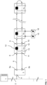
- FIG. 1 shows a schematic block diagram of an automation system. It will be understood by those skilled in the art that the automation system shown is only an example and that all elements, modules, components, participants and units belonging to the automation system can be designed differently but can still fulfill the basic functionalities described here.
- the automation system shown has a higher-level controller 1, which can be implemented, for example, with a programmable logic controller, PLC.
- PLC programmable logic controller
- Such a PLC 1 basically serves to control and regulate the process carried out by the automation system.
- PLCs 1 in automation systems also take on more advanced functions, such as visualization, alarming and recording of all data relating to the process and as such the PLC 1 acts as a human-machine interface.
- a PLC 1 usually has a modular structure and consists of individual components, each of which fulfills a different task.
- a PLC 1 usually consists of a central computing module (with one or more main processors and memory modules) and several modules with inputs and outputs.
- Such modular PLC 1 can be easily expanded by adding modules. It depends on the complexity of the process and the complexity of the structure of the automation system which modules must be integrated into the PLC 1. In today's automation systems, the PLC 1 is usually no longer an independent system, but rather the PLC 1 is connected to the Internet or intranet via appropriate interfaces - not shown here. This means that the PLC 1 is part of a network via which or from which the PLC 1 can receive information, instructions, programming, etc. For example, the PLC 1 can receive information about materials supplied to the process via a connection to a computer located on the intranet or Internet, so that the process can be optimally controlled, for example by knowing their number or nature.
- the PLC 1 is controlled by a user through access from the intranet or Internet.
- a user can use a computer, also called a master computer, to access the PLC 1 and check, change or correct its user programming.
- access to the PLC 1 is possible from one or more remote control centers or control centers.
- the master computers can, if necessary, have visualization devices for displaying process sequences.
- the PLC 1 is connected to automation devices. In order to keep the wiring effort to a minimum, bus systems are used for these connections.
- the PLC 1 is connected to a local bus master 3 of a subordinate local bus system by means of a higher-level bus 2, which in the exemplary embodiment shown here can be a field bus.
- a local bus master 3 of a local bus can be connected to the higher-level bus 2, as in the exemplary embodiment shown here, but also any other participants - not shown here - which are designed for communication with the PLC 1.
- the higher-level bus 2 is connected to the local bus master 3.
- the local bus master 3 has a first interface 4, which is designed in such a way that it communicates with the higher-level bus 2 can be connected.
- the interface 4 can, for example, have a receptacle in the form of a socket and the higher-level bus 2 can have a plug that can be received by the socket.
- the plug and the socket can be, for example, a modular plug and a modular socket, ie each wire of the higher-level bus 2 is electrically or optically connected to a connection in the modular socket.
- an interface 4 should be designed so that the local bus master 3 can be connected electrically or optically to the higher-level bus 2.
- the person skilled in the art is familiar with screw, rotary, click or plug connections, with the help of which an electrical or optical connection can be established.
- a male plug is usually held by a female counterpart.
- This recording usually not only creates the electrical or optical connection, but also ensures that the two parts are mechanically coupled and can only be separated from each other with the application of a certain force.
- the higher-level bus 2 is hard-wired to the interface 4.
- the local bus master 3 in the exemplary embodiment shown here has a further second interface in order to connect the local bus master 3 to the local bus.
- Data bus participants 7a, 7b, ..., 7n are connected to the local bus or form it.
- the local bus is advantageously designed in such a way that a data packet sent by the local bus master 3 is transmitted through all data bus participants 7a, 7b, ..., 7n connected to the local bus and back to the local bus master 3.
- a data bus subscriber 7a, 7b, ..., 7n always only receives a part of the data packet from its upstream data bus subscriber 7a, 7b, ..., 7n.
- the local bus is advantageously designed in a ring-shaped structure. Such local buses can also be referred to as ring bus 6.
- the local bus can alternatively also be designed in a strand-shaped or star-shaped manner or from a combination or mixed form of the aforementioned.
- the data packets are sent and received via the second interface of the local bus master 3.
- the second interface is divided into a first part 5a and a second part 5b.
- the first part 5a of the second interface establishes the downlink in the ring bus 6 and the second part 5b of the second interface establishes the uplink in the ring bus 6.
- the exemplary embodiment shown here has the data bus participants 7a, 7b, ..., 7n in the exemplary embodiment shown here.
- these data bus participants 7a, 7b, ..., 7n each have an interface 8 in order to receive data from an upstream or preceding data bus participant 7a, 7b, ..., 7n.
- data bus participant 7a it receives data from the upstream local bus master 3 via the interface 8.
- the data bus participants 7a, 7b, ..., 7n in the exemplary embodiment shown here each have an interface 9 in order to send data to a downstream or to forward the following data bus participants 7a, 7b, ..., 7n.
- interfaces 8 and 9 serve to propagate data in the downward direction of the ring bus 6, ie away from the local bus master 3.
- the data bus participants 7a, 7b, ..., 7n in this exemplary embodiment also have interfaces 10 and 11 for propagating data in the upward direction of the ring bus 6, ie to the local bus master 3.
- interface 10 is designed to receive data from the downstream or subsequent data bus subscriber 7b and interface 11 is designed to forward data to the upstream or preceding data bus subscriber, here the local bus master 3. So it can also be said that interfaces 9 and 11 are transmitter interfaces, whereas interfaces 8 and 10 are receiver interfaces.
- connections of the interfaces and the PLC 1 or the data bus participants 7a, 7b, ..., 7n are implemented using cables or circuit boards for direct or indirect contacting using electrical contacts.
- Another alternative is that the individual Connections are made wirelessly and the interfaces provide the necessary implementations to the radio standards used.
- the local bus master 3 is therefore arranged decentrally from the data bus participants 7a, 7b, ..., 7n
- the data bus participants 7a, 7b, ..., 7n and the local bus master 3 - which also represents a data bus participant of the ring bus 6 - can also be directly connected to one another.
- contacts of one data bus participant can engage in corresponding receptacles or receiving contacts of a directly adjacent data bus participant in order to establish an electrical connection between the data bus participants so that data can be sent in the downward and upward direction.
- the data bus participants 7a, 7b, ..., 7n can have receptacles on the side facing away from the master and contacts on the side facing the master. If the data bus participants 7a, 7b, ..., 7n are then lined up accordingly, the contacts of one data bus participant 7a, 7b, ..., 7n each engage in the receptacles of the other data bus participant 7a, 7b, ..., 7n and an electrical connection can be created.
- the local bus master 3 then has corresponding contacts on the side which engage in the receptacles of the first data bus subscriber 7a in order to create an electrical connection between the interfaces 5a and 8 or the interfaces 5b and 11.
- the person skilled in the art is also aware of other options, for example pressure contacts, knife and fork contacts, as to how two data bus participants 7a, 7b, ..., 7n arranged directly next to one another can establish an electrical or optical connection.
- the data bus participants 7a, 7b, ..., 7n and the local bus master 3 are to be connected directly to one another, they can also have mechanical receptacles or mechanical fastening means with which the individual data bus participants 7a, 7b, ..., 7n and the local bus master 3 can be connected to each other.
- a data bus subscriber 7a, 7b, ..., 7n can have a projection on one side and an undercut on the other side. If the data bus participants 7a, 7b, ..., 7n are then lined up next to one another, a projection engages in an undercut in the other data bus participant 7a, 7b, ..., 7n, so that a mechanical coupling is created.
- the data bus participants 7a, 7b, ..., 7n can also be arranged on a common receptacle, for example a top-hat rail.
- the data bus participants 7a, 7b, ..., 7n can have corresponding fastening means for fastening to the top-hat rail.
- the data bus participants 7a, 7b, ..., 7n can also have, for example, releasably connectable fastening means with which the data bus participants 7a, 7b, ..., 7n can be attached either to the top-hat rail or to another receptacle.
- the detachably connectable fastening means can be exchangeable and a corresponding fastening means for the desired receptacle can be connected to the data bus participants 7a, 7b, ..., 7n so that they can be fastened to the desired receptacle.
- the data bus participants 7a, 7b, ..., 7n in the in Figure 1 shown embodiment also has a processing unit 12.
- This processing unit 12 can be an arithmetic-logical unit or another type of arithmetic unit with the help of which data can be processed.
- the processing unit 12 is preferably an integral part of the data bus subscriber 7a, 7b, ..., 7n in order to ensure particularly fast and time-synchronized processing of the data.
- the processing unit 12 can also be referred to as the overall circuit of the data bus subscriber. This means that the processing device 12 receives data via inputs 8 and 10 and outputs data on outputs 9 and 11. Furthermore, the processing device 12 can receive or output data from the inputs and outputs 13 and 14. Furthermore, the processing unit 12 has access to a memory - not shown here - of the data bus subscriber 7a, 7b, ..., 7n in which, for example, data, process data or instruction lists are stored.
- the processing unit 12 can be designed to process received data and output data.
- Data to be processed can be received either from an upstream data bus subscriber or from inputs 13 of the data bus subscriber 7a, 7b, ..., 7n.
- the inputs 13 of the data bus subscriber 7a, 7b, ..., 7n can be connected to sensors 15, which send, for example, measurement data, status data, etc.
- Processed data can be output either to a downstream data bus subscriber or to outputs 14 of the data bus subscriber 7a, 7b, ..., 7n.
- the outputs 14 of the data bus subscriber 7a, 7b, ..., 7n can be connected to actuators 16, which, for example, carry out a specific action with the help of the data sent to them. If data processing is also to take place in the upward direction, data can also be received by a downstream data bus participant 7a, 7b, ..., 7n and processed data can be sent to an upstream data bus participant 7a, 7b, ..., 7n.
- the data bus participants 7a, 7b, ..., 7n are only shown with one input 13 and one output 14 and only data bus participant 7b is connected to sensor 15 and actuator 16.
- the data bus participants 7a, 7b, ..., 7n can have a large number of inputs and outputs 13 and 14, and can be connected to a large number of different sensors 15 and actuators 16.
- the feature that characterizes the sensors 15 is that the sensors 15 record data or signals and send them to the data bus participants 7a, 7b, ..., 7n, whereas actuators 16 receive data or signals from the data bus participants 7a, 7b, ..., 7n receive and perform an action based on this data or signal.
- the interfaces 8, 9, 10 and 11 can be integrated in a module unit and the data bus participants 7a, 7b, ..., 7n can be plugged onto this module unit.
- the module units can also be referred to as basic elements of the ring bus 6.
- the ring bus infrastructure is built up by the module units and the data bus participants 7a, 7b, ..., 7n are interchangeable, so that the ring bus 6 can be set up with any data bus participants 7a, 7b, ..., 7n.
- With the help of the module units it is also ensured that even if a data bus participant 7a, 7b, ..., 7n is removed, the communication between the remaining data bus participants 7a, 7b, ..., 7n is not interrupted because the communication via the existing modular units happens.
- the data bus participants 7a, 7b, ..., 7n shown in this exemplary embodiment are also often referred to as I/O modules due to their inputs and outputs 13, 14, which can be connected to sensors 15 or actuators 16. Also If the data bus participants 7a, 7b, ..., 7n are shown as spatially separated from the sensors 15 or actuators 16 in the exemplary embodiment shown here, the sensors 15 or actuators 16 can also be integrated in the I/O module.
- the ring bus 6 shown in the exemplary embodiment shown here is based on cycle frame communication.
- a cycle frame can be defined, for example, as a recurring (cyclic), preferably equidistant time interval in which data can be transferred on the ring bus 6.
- the cycle frame has, for example, at least one start identifier (SOC) and a time range for transmitting data.
- SOC start identifier
- Several start identifiers (SOC) of successive cycle frames are advantageously at a time equidistant from one another.
- the time range mentioned is intended for the transmission of data that can be transmitted within the cycle frame in the form of data packets.
- the start identifier (SOC) and the data packets are transmitted via the ring bus 6 and pass through all data bus participants 7a, 7b, ..., 7n.
- the cycle frame is advantageously initiated by the local bus master 3 in the ring bus 6.
- the start identifier (SOC) is separate, i.e. transferable as an independent symbol or advantageously contained in a start data package (SOC package).
- the cycle frame advantageously also has a trailer.
- the trailer has a variable length and follows the data transmission time range, preferably up to the following start identifier (SOC) of the next cycle frame.
- SOC start identifier
- the trailer advantageously has idle data.
- Each data packet is sent from the local bus master 3 in the downward direction to the first data bus subscriber 7a of the ring bus 6.
- the data bus subscriber 7a then processes the part and then forwards the part to the next data bus subscriber 7b via interface 9, preferably at the same time the first data bus subscriber 7a receives a second part of the data packet, etc.
- the size of the parts of the data packet i.e. the denomination of the data packet, depends on the recording capacity of the data bus participants 7a, 7b, ..., 7n, for example a fixed number of bits, for example 8 bits of the data packet, can be present on the data bus participants 7a, 7b, ..., 7n at the same time for processing.
- the data packet accordingly passes through the data bus participants 7a, 7b, ..., 7n in units, pieces, or parts, for example in parts or symbols of 8 bits.
- the part of the data packet that has been processed by the last data bus participant, in the exemplary embodiment shown here, data bus participant 7n then passes through the ring bus 6 in the upward direction, so that the parts, starting from the last data bus participant 7n, are sent back in the direction of the local bus master 3 through all data bus participants 7a, 7b, ..., 7n upwards.
- the last data bus participant 7n either has a switchable bridge that connects the interface 9 to the interface 10 or a switchable bridge - not shown here - is connected to the last data bus participant 7n, which takes over the function of the parts of the data packet from the interface 9 to route to interface 10.
- the interface 10 of the data bus subscriber 7n can also be connected directly to the interface 5b of the local bus master 3 using a bypass line - not shown here.
- the units of the data packet or data packets can be looped back to the local bus master 3 by the individual data bus participants 7a, 7b, ..., 7n, as in the exemplary embodiment shown here, without any further processing taking place.
- the units of the data packet are processed again in the upward direction, so that the data packet can be processed twice, once in the downward direction to the last data bus subscriber 7n and once in the upward direction to the local bus master 3.
- processing can take place in the upward direction by signal refreshing and/or phase shifting.
- the processing is accomplished with the aid of instruction lists, the instruction lists containing sets of instructions which are sent by the processing unit 12 of the data bus subscriber 7a , 7b, ..., 7n can be executed.
- the instruction lists themselves can be sent to the individual data bus participants 7a, 7b, ..., 7n in an initialization phase by the local bus master 3 or can advantageously be sent to the data bus participants 7a, 7b, ..., 7n during ongoing communication, so that programming of the data bus participants 7a, 7b, ..., 7n takes place without interrupting communication.
- the instruction list index informs the data bus participant which stored instruction list should be used.
- An instruction list index is therefore assigned to an instruction list or vice versa, so that the instruction list to be used can be identified with the help of the instruction list index.
- the instruction list index preferably has a value that is assigned to an instruction list, for example the value indicates a specific instruction list or its storage location.
- the value itself can be the memory address where the instruction list is stored or where at least a first instruction of the instruction list is stored.
- the value can also indicate a memory area in which the corresponding instruction list is stored.
- the value of the instruction list index can also be used, for example, as input to a translation table ( lookup table, LUT).
- the value of the instruction list index is the input value of the conversion table.
- the output value of the translation table may be the memory address of the first instruction in the associated instruction list or otherwise identify the instruction list.
- the conversion table can be stored in software and hardware technology in the form of, for example, logic and a unique conversion from one input value to one Specify the initial value, where the initial value provides an indication of the instruction list to be used. It depends on the conversion table how a connection is established between the instruction list index and the instruction list.
- the instruction list to be used by the data bus subscriber can be clearly identified, ie found, via the instruction list index.
- the instruction list index can be inserted into the data packet before the process data to be processed, so that the data bus participants 7a, 7b, ..., 7n can use the corresponding instruction list according to the order of the process data in the data packet.
- the instruction lists have instructions that are adapted to the order of the process data in the data package.
- the instruction lists can, for example, have a "SKIP" instruction for process data that is not addressed to the data bus subscriber 7a, 7b, ..., 7n, i.e.
- the instruction list for process data that is addressed to the data bus participant 7a, 7b, ..., 7n can have corresponding instructions for processing the process data.
- the processing of the process data can thus be decoupled from the actual position of the process data in the data packet, since the data bus participants are adapted to the order of the process data in the data packet using the instruction lists.
- the local bus master 3 is used in the exemplary embodiment shown here.
- the device responsible for the implementation in the local bus master 3 is in Figure 2 shown.
- FIG. 2 shows a block diagram of an exemplary embodiment of the device according to the invention arranged in the local bus master 3.
- the local bus master 3 is connected to the fieldbus 2 via the interface 4 and to the ring bus 6 via the interface 5.
- the interface 4 can accordingly also be referred to as a fieldbus interface, whereas the Interface 5 can be referred to as a local bus interface.
- Processing units can be connected to the interfaces 4, 5, a first unit 17 can be connected to the fieldbus interface 4, which can also be referred to as a fieldbus core (FBC), and a second unit 19 can be connected to the local bus interface 5, which can also be referred to as Local bus core (LBC) can be called.
- FBC fieldbus core
- LBC Local bus core
- the FBC 17 and the LBC 19 are connected to a data management unit 18 via a parallel bus.
- the parallel bus can be a 32-bit parallel bus and a computing unit, for example a microcontroller, ⁇ C or a processor, which is able to control the FBC 17, the data management unit 18, and the LBC 19, can also be connected to this.
- the data management unit 18 is adapted to transfer first symbols from the FBC 17 to the LBC 19 in a sequence-dependent manner, for example in an unchanged order, so that they can be sent to the ring bus 6 via the local bus interface 5 contained in at least one data packet.
- the first symbols can be process data that was received via the fieldbus 2 via the interface 4 at the FBC 17.
- the LBC 19 can be adapted to generate successive, local bus-compliant data packets for transmitting the process data on the local bus 6 and to insert the process data received from the data management unit 18 into the corresponding data packet.
- the order of the process data can be retained, that is, the process data has the same order in the data packet in the local bus as the order in which the process data was received at the FBC 17 via the fieldbus interface 4.
- 17 fieldbus telegrams from the fieldbus 2 are received at the FBC via the fieldbus interface 4; the fieldbus telegrams have process data in the form of first symbols with a fixed number of bits, for example 8 bits, i.e. 1 byte. These first symbols are arranged in a first order in the fieldbus telegram.
- the data management unit 18 is adapted to copy the process data from the FBC 17 to the LBC 19.
- the LBC 19 is adapted to generate a data packet of the local bus 6, the data packet containing the first symbols of the process data in a second order and the first order and the second order of the symbols matching.
- the data bus participants 7a, 7b, ..., 7n are connected using instruction lists and a Instruction list index set up to evaluate the process data in the data package.
- the instruction list index is placed in front of the process data in the data package.
- the data management unit 18 is adapted to transfer second symbols from the LBC 19 in a sequence-dependent manner, for example unchanged to the FBC 17, so that these can be sent to the fieldbus 2 via the fieldbus interface 4. The second symbols have been received from the local bus 6 at the LBC 19 via the local bus interface 5.
- the local bus interface 5 is divided into two parts, namely parts 5a and 5b, with data being sent in the downward direction to the local bus 6 via part 5a and in the downward direction via part 5b Upward direction can be received from local bus 6.
- the data management unit 18 also has a first and second master interface 18a and 18b.
- the first master interface 18a is connected to a slave interface 17a of the FBC 17. That is, the data management unit 18 and the FBC 17 are in a master-slave relationship, in this case the control comes from the data management unit 18.
- the data management unit 18 therefore reads data from the FBC 17 or writes data into the FBC 17 at a time specified by the data management unit 18.
- the second master interface 18b of the data management unit 18 is connected to a slave interface 19a of the LBC 19.
- the data management unit 18 and the LBC 19 also have a master-slave relationship. This means that the data management unit 18 controls the transfer of data between the FBC 17 and the LBC 19, particularly in both directions.
- the data management unit 18 and the LBC 19 are connected via a further line 25.
- Validity information regarding the transferred symbols can be exchanged between the data management unit 18 and the LBC 19 via this further line 25. This validity information can then be used to delay the sending of the first and second symbols on the fieldbus 2 and the local bus 6, respectively.
- connections between the units are advantageously designed as buses.
- a bus can advantageously be a 32-bit parallel bus.
- the connection can be any other connection that allows the above-described data transfer between the units.
- Figure 3a shows a schematic block diagram of an exemplary embodiment of the device according to the invention implemented in a local bus master 3 of a ring bus 6.
- the first interface 4 of the local bus master 3 receives a fieldbus telegram 20 from the fieldbus 2.
- This fieldbus telegram 20 contains an example of 10 bytes, represented by square boxes , where each box represents 1 byte, i.e. 8 bits. Only the four boxes shown in black, which correspond to 4 bytes, contain first process data 21.
- the other 6 bytes of the fieldbus telegram 20 are information corresponding to the bus protocol used on the fieldbus 2.
- the first process data 21 is also marked here as [1], [ 2], [3] and [4], which symbolizes their order.
- the first process data 21 are selected from the fieldbus telegram 20 by the FBC 17 and stored, for example, in a buffer - not shown here. The selection can consist of the FBC 17 only transferring the process data 21 to a buffer, but ignoring the other bytes of the fieldbus telegram 20.
- the data management unit 18 has a first data transfer unit 22, which reads the process data 21 from the buffer of the FBC 17 via the master-slave interface connection 17a, 18a and then transfers the process data 21 into a buffer - not shown here LBC 19 writes over the master-slave interface connection 18b, 19a.
- the first data transfer unit 22 copies process data 21 from the FBC 17 into the LBC 19. The copying can be done according to instructions and the first data transfer unit 22 can be adapted to precede and/or append further data to the process data 21 and/or between the process data 21 to insert.
- the LBC 19 can be adapted to provide additional data to the process data 21 to prefix and/or append and/or to insert between the process data 21 and/or to change the process data 21.
- the further data from the LBC 19 can be used to convert the process data 21 into a local bus-compliant format, for example into a data packet that can be sent to the local bus 6.
- the process data 21 is preceded by a symbol and a symbol is added to generate a data packet 24 which carries the process data 21.
- the first data transfer unit 22 can be further adapted to communicate the validity of the process data 21 to the LBC 19 after copying the process data 21 into the LBC 19.
- the validity can be communicated via the connection 25. Only when the LBC 19 receives a signal that the copied process data 21 is valid can the LBC 19 send it in the downward direction to the local bus 6 via the local bus interface 5a.
- the validity of the process data 21 is determined, for example, using a CRC or a valid bit.
- parts of the data packet 24 generated by the LBC 19 can be sent to the local bus 6 even before the validity display.
- the parts of the data packet 24 are the data bus participants 7a, 7b, ..., 7n - as in Figure 1 shown - run through successively, ie at any given time only a part of the data packet 24 is sent by the local bus master 3, which is then forwarded by the individual data bus participants 7a, 7b, ..., 7n.
- the LBC 19 can send the part of the data packet 24 to the local bus 6 that contains the process data or other information before the validity display.
- the LBC 19 can already send the attached symbol as the first part of the data packet 24 to the local bus 6.
- the first data transfer unit 22 thus copies process data 21 from the fieldbus 2 to the local bus 6.
- the order [1], [2], [3], [4] of the process data 21 is retained, that is, the order of the process data 21 is the same in the fieldbus telegram 20 and in the data packet 24 of the local bus 6.
- the Process data 21 is copied bus-neutrally, that is, without the bus-specific information with which the process data 21 is received. In the exemplary embodiment shown here, the preceding two symbols and the added four symbols of the fieldbus telegram 20 are not copied.
- Figure 3b shows a schematic block diagram of an exemplary embodiment of the device according to the invention implemented in a local bus master 3 of a ring bus 6.
- the second interface 5b of the local bus master 3 receives a data packet 26.
- the data packet 26 contains an example of 6 bytes, represented by square boxes, each Box represents 1 byte, i.e. 8 bits. Only the four boxes shown in black, which correspond to 4 bytes, contain second process data 27.
- the other 2 bytes of the data packet 26 are information corresponding to the bus protocol used on the local bus 6.
- the second process data 27 are also marked here as [1'], [2'], [3'] and [4'], which symbolizes their order.
- the second process data 27 can be based on the first process data 21 - as in Figure 3a shown - and can represent the process data 21 after it has passed through, ie its processing, through the local bus 6.
- the process data 27 are selected from the data packet 26 by the LBC 19 and stored, for example, in a buffer - not shown here.
- the selection can consist of the LBC 19 only transferring the process data 27 to a buffer, but ignoring the other bytes of the data packet 26.
- the data management unit 18 has a second data transfer unit 23, which reads the process data 27 from the buffer of the LBC 19 via the master-slave interface connection 18b, 19a and then the process data 27 into a buffer of the FBC 17 via the master -Slave interface connection 17a, 18a writes. Ie the second data transfer unit 23 copies process data 27 from the LBC 19 into the FBC 17. The copying can be done according to instructions and the second data transfer unit 23 can be adapted to precede and/or append further data to the process data 27 and/or between the process data 27 to insert and/or change the process data. Alternatively or additionally, the FBC 17 can be adapted to precede and/or append further data to the process data 27 and/or between them Insert process data 27.
- the further data from the FBC 17 can be used to convert the process data 27 into a fieldbus-compliant format, for example in Fedbus telegram 28 of the fieldbus 2.
- the process data 27 is preceded by two symbols and four symbols are added to generate one Fieldbus telegram 28, which carries the process data 27.
- the person skilled in the art is aware that even if only a specific number of symbols are prefixed and appended to the process data 27, this can also be any number of symbols, with the number depending solely on the fieldbus telegram format used, which is on the fieldbus 2 is used.
- the second data transfer unit 23 can be further adapted to copy only part of the process data 27 into the FBC 17 and to copy the remaining process data 27 only after receiving a validity indication from the LBC 19 via the connection 25. This allows the second data transfer unit 23 to control the time at which the fieldbus telegram 28 is sent by the FBC 17, because this is always sent directly when the fieldbus telegram 28 is completely filled with process data 27. If this is not yet the case, no fieldbus telegram 28 will be sent. This allows control between the second data transfer unit 23 and the FBC 17 without the need for a further connection.
- the validity of the process data 27 is determined using a CRC.
- the components of the device according to the invention described in the described exemplary embodiment as separate units, modules or interfaces can be implemented as separate hardware or can be integrated on the same semiconductor chip and their function can be implemented by hardware consisting of logic gates.
- the units, modules, or interfaces can be implemented on an FPGA/ASIC.
Claims (18)
- Un dispositif (3) pour le couplage d'un bus de terrain (2) avec un bus local (6), le dispositif (3) incluant :une première unité (17) reliable au bus de terrain (2) et adaptée pour l'émission et la réception de données dans un format conforme au bus de terrain par l'intermédiaire du bus de terrain (2),la première unité (17) étant adaptée pour sélectionner des premiers symboles à partir des données reçues ;une deuxième unité (19) reliable au bus local (6) et adaptée pour l'émission et la réception de données par l'intermédiaire du bus local (6) dans au moins un paquet de données (24) ;une unité de gestion de données (18) qui est reliée à la première unité (17) et à la deuxième unité (19), l'unité de gestion de données (18) étant adaptée pour le transfert, en fonction de l'ordre, seulement des premiers symboles (21) sélectionnés par la première unité (17) vers la deuxième unité (19), les premiers symboles sélectionnés (21) étant seulement des données de processus ; etla deuxième unité (19) étant adaptée pour émettre l'au moins un paquet de données (24) contenant les premiers symboles (21) sur le bus local (6).
- Le dispositif (3) selon la revendication 1, dans lequel l'unité de gestion de données (18) est adaptée pour faire précéder et/ou ajouter des symboles supplémentaires aux premiers symboles (21).
- Le dispositif (3) selon une des revendications précédentes, dans lequel l'unité de gestion de données (18) est adaptée pour mettre les premiers symboles (21) en mémoire tampon.
- Le dispositif (3) selon une des revendications précédentes, dans lequel la deuxième unité (19) est adaptée pour générer l'au moins un paquet de données (24) comportant les premiers symboles (21).
- Le dispositif (3) selon une des revendications précédentes, dans lequel l'au moins un paquet de données (24) contient des deuxièmes symboles (27).
- Le dispositif (3) selon la revendication 5, dans lequel la deuxième unité (19) est également adaptée pour la manipulation des deuxièmes symboles (27).
- Le dispositif (3) selon une des revendications précédentes, dans lequel la deuxième unité (19) est également adaptée pour la manipulation des premiers symboles (21).
- Le dispositif (3) selon la revendication 4, dans lequel le bus local (6) est un bus en anneau, et des temps de cycles d'un cadre cyclique pour l'au moins un paquet de données (24) sont adaptés aux temps de cycles du bus de terrain (2).
- Le dispositif (3) selon une des revendications précédentes, dans lequel l'unité de gestion de données (18) comporte une première interface maîtresse (18a) qui est reliée à une interface esclave (17a) de la première unité (17),
et/ou
dans lequel l'unité de gestion de données (18) comporte une deuxième interface maîtresse (18b) qui est reliée à une interface esclave (19a) de la deuxième unité (19). - Le dispositif (3) selon la revendication 9, dans lequel l'unité de gestion de données (18) comporte une première unité de transfert de données (22), la première unité de transfert de données (22) étant adaptée, sur la base de premières instructions, pour lire par l'intermédiaire de la première interface maîtresse (18a) les premiers symboles (21) à partir d'une mémoire tampon de la première unité (17) et, par l'intermédiaire de la deuxième interface maîtresse (18b), pour les écrire dans une mémoire tampon de la deuxième unité (19) .
- Le dispositif (3) selon la revendication 10, dans lequel l'unité de gestion de données (18) est adaptée pour émettre les premiers symboles reçus (21) au moyen de la première unité de transfert de données (22) par l'intermédiaire de la deuxième interface maîtresse (18b) vers la deuxième unité (19) s'il y a validité des premiers symboles reçus (21).
- Le dispositif (3) selon une des revendications 9 à 11, dans lequel l'unité de gestion de données (18) comporte une deuxième unité de transfert de données (23), la deuxième unité de transfert de données (23) étant adaptée, sur la base de deuxièmes instructions, pour lire par l'intermédiaire de la deuxième interface maîtresse (18b) des deuxièmes symboles (27) sur une mémoire tampon de la deuxième unité (19) et, par l'intermédiaire de la première interface maîtresse (18a), pour les écrire dans une mémoire tampon de la première unité (17).
- Le dispositif (3) selon la revendication 12, dans lequel l'unité de gestion de données (18) est adaptée pour écrire les deuxièmes symboles (27), au moyen de la deuxième unité de transfert de données (23), par l'intermédiaire de la première interface maîtresse (18a) dans la mémoire tampon de la première unité (17) si une validité des deuxièmes symboles (27) est donnée.
- Le dispositif (3) selon une des revendications précédentes, comprenant en outre :une unité de calcul adaptée pourcommander la première unité (17) et/ou l'unité de gestion de données (18) et/ou la deuxième unité (19) ; et/ou pour analyser les premiers et deuxièmes symboles (21, 27).
- Le dispositif (3) selon une des revendications précédentes, dans lequel la première unité (17) est adaptée pour vérifier la validité des données reçues par l'intermédiaire du bus de terrain (2), et la deuxième unité (19) est adaptée pour vérifier la validité des paquets de données reçus par l'intermédiaire du bus local (6).
- Le dispositif (3) selon une des revendications précédentes,dans lequel la première unité (17) est adaptée pour l'émission et la réception en série de données par l'intermédiaire du bus de terrain (2) ;dans lequel la deuxième unité (19) est adaptée pour l'émission et la réception en série de données par l'intermédiaire du bus local (6) ;dans lequel l'unité de gestion de données (18) est reliée à la première unité (17) par l'intermédiaire d'un bus parallèle ; etdans lequel l'unité de gestion de données (18) est reliée à la deuxième unité (19) par l'intermédiaire d'un bus parallèle.
- Le dispositif (3) selon une des revendications précédentes,dans lequel la première unité (17) est conformée en un premier circuit logique pour la communication avec le bus de terrain (2) ;dans lequel la deuxième unité (19) est conformée en un deuxième circuit logique pour la communication avec le bus local (6) ; etdans lequel le premier circuit logique et le deuxième circuit logique sont agencés pour effectuer des opérations de calcul indépendantes les unes des autres.
- Un procédé pour le transfert de données entre un bus de terrain (2) et un bus local (6), au moins un participant de bus de données (7a, 7b, ..., 7n) étant relié au bus local (6), le procédé comprenant :la réception de données par l'intermédiaire du bus de terrain (2) au niveau d'une première unité (17), les données reçues contenant des premiers symboles (21) dans un format conforme au bus de terrain ;la sélection par la première unité (17) des premiers symboles (21) à partir des données reçues, les premiers symboles (21) étant seulement des données de processus ;le transfert, en fonction de l'ordre, seulement des premiers symboles (21) vers une deuxième unité (19) ; etl'émission d'au moins un paquet de données (24) sur le bus local (6) par la deuxième unité (19) contenant les premiers symboles (21) transférés.
Applications Claiming Priority (2)
| Application Number | Priority Date | Filing Date | Title |
|---|---|---|---|
| DE102017208824.9A DE102017208824B4 (de) | 2017-05-24 | 2017-05-24 | Busumsetzer |
| PCT/EP2018/062971 WO2018215305A1 (fr) | 2017-05-24 | 2018-05-17 | Convertisseur de données de bus |
Publications (2)
| Publication Number | Publication Date |
|---|---|
| EP3632050A1 EP3632050A1 (fr) | 2020-04-08 |
| EP3632050B1 true EP3632050B1 (fr) | 2024-01-31 |
Family
ID=62200454
Family Applications (1)
| Application Number | Title | Priority Date | Filing Date |
|---|---|---|---|
| EP18725828.0A Active EP3632050B1 (fr) | 2017-05-24 | 2018-05-17 | Convertisseur de données de bus |
Country Status (5)
| Country | Link |
|---|---|
| US (2) | US11558217B2 (fr) |
| EP (1) | EP3632050B1 (fr) |
| CN (2) | CN116232800A (fr) |
| DE (1) | DE102017208824B4 (fr) |
| WO (1) | WO2018215305A1 (fr) |
Families Citing this family (3)
| Publication number | Priority date | Publication date | Assignee | Title |
|---|---|---|---|---|
| CN113542090B (zh) * | 2020-04-14 | 2023-07-14 | 宁波弘讯科技股份有限公司 | 一种EtherCAT主从站一体网桥控制器及控制方法 |
| US20210117359A1 (en) * | 2020-12-24 | 2021-04-22 | Krishna Kumar Nagar | User Signals for Data Transmission Over a Bus Interface Protocol |
| DE102022120561A1 (de) | 2022-08-16 | 2024-02-22 | Turck Holding Gmbh | MODULBUS-Segment und Verfahren zur Automation einer Behandlungsanlage |
Citations (2)
| Publication number | Priority date | Publication date | Assignee | Title |
|---|---|---|---|---|
| US20040054829A1 (en) * | 2001-06-25 | 2004-03-18 | White William A. | Method, system and program for the transmission of modbus messages between networks |
| DE10304637A1 (de) * | 2003-02-04 | 2004-08-19 | Elektro Beckhoff Gmbh Unternehmensbereich Industrie Elektronik | Netzwerk-Koppler, Netzwerk und Datenverarbeitungsverfahren für Ethernet-Telegramme |
Family Cites Families (21)
| Publication number | Priority date | Publication date | Assignee | Title |
|---|---|---|---|---|
| US5472347A (en) | 1993-09-17 | 1995-12-05 | Allen-Bradley Company, Inc. | System for interconnecting I/O modules for data communications over a common backplane |
| JP3543647B2 (ja) * | 1998-10-27 | 2004-07-14 | セイコーエプソン株式会社 | データ転送制御装置及び電子機器 |
| DE19955330A1 (de) | 1999-11-17 | 2001-05-31 | Siemens Ag | Verfahren zur Übertragung von Daten sowie Koppelgerät |
| DE10163342A1 (de) * | 2001-12-21 | 2003-07-10 | Elektro Beckhoff Gmbh Unterneh | Datenübertragungsverfahren, serielles Bussystem und Anschalteinheit für einen passiven Busteilnehmer |
| US20040063438A1 (en) | 2002-10-01 | 2004-04-01 | Hsu Yun-Hsiang Kenny | Wireless point to multipoint system |
| US20080123522A1 (en) * | 2006-07-28 | 2008-05-29 | David Charles Elliott | Redundancy coupler for industrial communications networks |
| CN101529820B (zh) * | 2006-11-03 | 2013-06-19 | 索尤若驱动有限及两合公司 | 用于总线仲裁的方法和装置、变频器和加工设备 |
| DE102008018633B4 (de) | 2008-04-11 | 2013-10-10 | Phoenix Contact Gmbh & Co. Kg | Verfahren, Buskomponenten und Steuerungssystem zur Ethernet-basierten Steuerung eines Automatisierungssystems |
| DE102008053534B3 (de) * | 2008-10-28 | 2010-01-14 | Atmel Automotive Gmbh | Sklavenschaltung eines LIN-Busses und Verfahren zum Betrieb |
| DE102010020446B4 (de) * | 2010-05-12 | 2012-12-06 | Wago Verwaltungsgesellschaft Mbh | Automatisierungsgerät und Verfahren zur beschleunigten Verarbeitung von selektierten Prozessdaten |
| CN102170430B (zh) * | 2011-03-24 | 2013-06-19 | 华中科技大学 | 一种多端口多网络协议转换器 |
| US20150156286A1 (en) * | 2012-06-07 | 2015-06-04 | Schneider Electric Industries Sas | Message tunneling in an industrial network |
| CN103293995B (zh) * | 2013-06-09 | 2016-01-20 | 南车株洲电力机车研究所有限公司 | 基于微控制器的现场总线通信模块 |
| MX2016004507A (es) | 2013-10-11 | 2016-08-19 | Raise Production Inc | Sistema de valvula de cruce y metodo para produccion de gas. |
| WO2015103469A1 (fr) * | 2014-01-03 | 2015-07-09 | Brian Vogt | Réseau de bus de terrain avec une boucle à deux fils |
| US9749164B2 (en) * | 2014-07-23 | 2017-08-29 | Massachusetts Institute Of Technology | Asynchronous digital communication |
| US20160217242A1 (en) * | 2015-01-23 | 2016-07-28 | Garrett Beaubien | System and Method of Fieldbus Vitual Device Instantiation and Simulation of Segment |
| DE102015101057B4 (de) * | 2015-01-26 | 2017-03-02 | Endress + Hauser Process Solutions Ag | Gerätezugriff mittels eines generischen Kommunikationstreibers |
| EP3086498A1 (fr) | 2015-04-24 | 2016-10-26 | Alcatel Lucent | Procédé et appareil pour générer un deuxième paquet de données à partir d'un premier paquet |
| JP6717059B2 (ja) * | 2016-06-06 | 2020-07-01 | オムロン株式会社 | 制御システム |
| DE102017002805B4 (de) * | 2017-03-23 | 2018-10-04 | WAGO Verwaltungsgesellschaft mit beschränkter Haftung | Verfahren zum Betrieb eines Bussystems eines Automatisierungssystems |
-
2017
- 2017-05-24 DE DE102017208824.9A patent/DE102017208824B4/de active Active
-
2018
- 2018-05-17 CN CN202310261919.5A patent/CN116232800A/zh active Pending
- 2018-05-17 WO PCT/EP2018/062971 patent/WO2018215305A1/fr active Application Filing
- 2018-05-17 EP EP18725828.0A patent/EP3632050B1/fr active Active
- 2018-05-17 CN CN201880034583.6A patent/CN110663227B/zh active Active
-
2019
- 2019-11-25 US US16/694,432 patent/US11558217B2/en active Active
-
2023
- 2023-01-04 US US18/093,105 patent/US11929848B2/en active Active
Patent Citations (2)
| Publication number | Priority date | Publication date | Assignee | Title |
|---|---|---|---|---|
| US20040054829A1 (en) * | 2001-06-25 | 2004-03-18 | White William A. | Method, system and program for the transmission of modbus messages between networks |
| DE10304637A1 (de) * | 2003-02-04 | 2004-08-19 | Elektro Beckhoff Gmbh Unternehmensbereich Industrie Elektronik | Netzwerk-Koppler, Netzwerk und Datenverarbeitungsverfahren für Ethernet-Telegramme |
Also Published As
| Publication number | Publication date |
|---|---|
| DE102017208824A1 (de) | 2018-11-29 |
| WO2018215305A1 (fr) | 2018-11-29 |
| CN110663227A (zh) | 2020-01-07 |
| US11929848B2 (en) | 2024-03-12 |
| US11558217B2 (en) | 2023-01-17 |
| US20200092133A1 (en) | 2020-03-19 |
| CN110663227B (zh) | 2023-05-12 |
| CN116232800A (zh) | 2023-06-06 |
| DE102017208824B4 (de) | 2022-12-29 |
| EP3632050A1 (fr) | 2020-04-08 |
| US20230139414A1 (en) | 2023-05-04 |
Similar Documents
| Publication | Publication Date | Title |
|---|---|---|
| EP1368942B1 (fr) | Procede et systeme pour coupler des reseaux de donnees | |
| EP3632040B1 (fr) | Traitement de données de processus | |
| EP3632050B1 (fr) | Convertisseur de données de bus | |
| EP1502400A2 (fr) | Procede et systeme de transmission de donnees par des reseaux de donnees commutables | |
| EP1435027B1 (fr) | Procede pour transmettre un telegramme de donnees entre un domaine en temps reel et un domaine non en temps reel et unite de couplage | |
| EP3632056B1 (fr) | Intitialisation d'un bus local | |
| EP3632054B1 (fr) | Determination de noeuds d'un bus de données local | |
| EP3972205B1 (fr) | Traitement des données de processus | |
| EP1371184B1 (fr) | Circuit de commutation electronique et procede destines a une interface de communication avec memoire tampon intermediaire | |
| EP3631630B1 (fr) | Traitement distribué de données de processus | |
| EP3632055B1 (fr) | Transmission de données sur un bus local | |
| EP1371185A2 (fr) | Procede et circuit electronique pour interface de communication dans des composants d'automatisation | |
| DE102017012250B4 (de) | Übertragen von Daten auf einem Lokalbus | |
| EP1593235A1 (fr) | Systeme de communication deterministe | |
| WO2018215295A1 (fr) | Initialisation d'abonnés de bus de données | |
| WO2002078252A2 (fr) | Circuit electronique et procede pour interface de communication a memoire tampon pseudo-transit | |
| WO2018215293A1 (fr) | Préchargement d'instructions |
Legal Events
| Date | Code | Title | Description |
|---|---|---|---|
| STAA | Information on the status of an ep patent application or granted ep patent |
Free format text: STATUS: UNKNOWN |
|
| STAA | Information on the status of an ep patent application or granted ep patent |
Free format text: STATUS: THE INTERNATIONAL PUBLICATION HAS BEEN MADE |
|
| PUAI | Public reference made under article 153(3) epc to a published international application that has entered the european phase |
Free format text: ORIGINAL CODE: 0009012 |
|
| STAA | Information on the status of an ep patent application or granted ep patent |
Free format text: STATUS: REQUEST FOR EXAMINATION WAS MADE |
|
| 17P | Request for examination filed |
Effective date: 20191112 |
|
| AK | Designated contracting states |
Kind code of ref document: A1 Designated state(s): AL AT BE BG CH CY CZ DE DK EE ES FI FR GB GR HR HU IE IS IT LI LT LU LV MC MK MT NL NO PL PT RO RS SE SI SK SM TR |
|
| AX | Request for extension of the european patent |
Extension state: BA ME |
|
| DAV | Request for validation of the european patent (deleted) | ||
| DAX | Request for extension of the european patent (deleted) | ||
| STAA | Information on the status of an ep patent application or granted ep patent |
Free format text: STATUS: EXAMINATION IS IN PROGRESS |
|
| 17Q | First examination report despatched |
Effective date: 20211221 |
|
| P01 | Opt-out of the competence of the unified patent court (upc) registered |
Effective date: 20230522 |
|
| REG | Reference to a national code |
Ref country code: DE Ref legal event code: R079 Ref document number: 502018014059 Country of ref document: DE Free format text: PREVIOUS MAIN CLASS: H04L0012400000 Ipc: H04L0012420000 Ref country code: DE Ref legal event code: R079 Free format text: PREVIOUS MAIN CLASS: H04L0012400000 Ipc: H04L0012420000 |
|
| GRAP | Despatch of communication of intention to grant a patent |
Free format text: ORIGINAL CODE: EPIDOSNIGR1 |
|
| STAA | Information on the status of an ep patent application or granted ep patent |
Free format text: STATUS: GRANT OF PATENT IS INTENDED |
|
| RIC1 | Information provided on ipc code assigned before grant |
Ipc: H04L 12/46 20060101ALI20230717BHEP Ipc: H04L 12/40 20060101ALI20230717BHEP Ipc: H04L 12/42 20060101AFI20230717BHEP |
|
| INTG | Intention to grant announced |
Effective date: 20230823 |
|
| GRAS | Grant fee paid |
Free format text: ORIGINAL CODE: EPIDOSNIGR3 |
|
| GRAA | (expected) grant |
Free format text: ORIGINAL CODE: 0009210 |
|
| STAA | Information on the status of an ep patent application or granted ep patent |
Free format text: STATUS: THE PATENT HAS BEEN GRANTED |
|
| AK | Designated contracting states |
Kind code of ref document: B1 Designated state(s): AL AT BE BG CH CY CZ DE DK EE ES FI FR GB GR HR HU IE IS IT LI LT LU LV MC MK MT NL NO PL PT RO RS SE SI SK SM TR |
|
| REG | Reference to a national code |
Ref country code: GB Ref legal event code: FG4D Free format text: NOT ENGLISH Ref country code: CH Ref legal event code: EP |
|
| REG | Reference to a national code |
Ref country code: DE Ref legal event code: R096 Ref document number: 502018014059 Country of ref document: DE |
|
| REG | Reference to a national code |
Ref country code: IE Ref legal event code: FG4D Free format text: LANGUAGE OF EP DOCUMENT: GERMAN |