EP3632050B1 - Bus converter - Google Patents
Bus converter Download PDFInfo
- Publication number
- EP3632050B1 EP3632050B1 EP18725828.0A EP18725828A EP3632050B1 EP 3632050 B1 EP3632050 B1 EP 3632050B1 EP 18725828 A EP18725828 A EP 18725828A EP 3632050 B1 EP3632050 B1 EP 3632050B1
- Authority
- EP
- European Patent Office
- Prior art keywords
- data
- unit
- bus
- symbols
- local bus
- Prior art date
- Legal status (The legal status is an assumption and is not a legal conclusion. Google has not performed a legal analysis and makes no representation as to the accuracy of the status listed.)
- Active
Links
- 238000000034 method Methods 0.000 claims description 156
- 230000008569 process Effects 0.000 claims description 150
- 238000013523 data management Methods 0.000 claims description 60
- 238000012546 transfer Methods 0.000 claims description 42
- 230000001419 dependent effect Effects 0.000 claims description 8
- 230000008878 coupling Effects 0.000 claims description 2
- 238000010168 coupling process Methods 0.000 claims description 2
- 238000005859 coupling reaction Methods 0.000 claims description 2
- 238000012545 processing Methods 0.000 description 22
- 101100408464 Caenorhabditis elegans plc-1 gene Proteins 0.000 description 20
- 238000004891 communication Methods 0.000 description 12
- 238000011144 upstream manufacturing Methods 0.000 description 12
- 238000006243 chemical reaction Methods 0.000 description 10
- 238000010586 diagram Methods 0.000 description 8
- 230000005540 biological transmission Effects 0.000 description 7
- 230000008859 change Effects 0.000 description 5
- 230000006870 function Effects 0.000 description 5
- 238000005259 measurement Methods 0.000 description 5
- 230000001276 controlling effect Effects 0.000 description 4
- 239000004065 semiconductor Substances 0.000 description 4
- 238000007726 management method Methods 0.000 description 3
- 230000003287 optical effect Effects 0.000 description 3
- 230000009471 action Effects 0.000 description 2
- 230000008901 benefit Effects 0.000 description 2
- 230000003139 buffering effect Effects 0.000 description 2
- 238000005516 engineering process Methods 0.000 description 2
- 230000001105 regulatory effect Effects 0.000 description 2
- 230000000717 retained effect Effects 0.000 description 2
- 238000000926 separation method Methods 0.000 description 2
- 230000001360 synchronised effect Effects 0.000 description 2
- 230000007704 transition Effects 0.000 description 2
- 238000013519 translation Methods 0.000 description 2
- 238000012800 visualization Methods 0.000 description 2
- 230000001427 coherent effect Effects 0.000 description 1
- 125000004122 cyclic group Chemical group 0.000 description 1
- 230000001934 delay Effects 0.000 description 1
- 230000003111 delayed effect Effects 0.000 description 1
- 238000013461 design Methods 0.000 description 1
- 238000011156 evaluation Methods 0.000 description 1
- 208000025697 familial rhabdoid tumor Diseases 0.000 description 1
- 238000009434 installation Methods 0.000 description 1
- 238000012423 maintenance Methods 0.000 description 1
- 239000000463 material Substances 0.000 description 1
- 238000012544 monitoring process Methods 0.000 description 1
- 238000013439 planning Methods 0.000 description 1
- 230000001902 propagating effect Effects 0.000 description 1
- 230000008707 rearrangement Effects 0.000 description 1
Images


Classifications
-
- H—ELECTRICITY
- H04—ELECTRIC COMMUNICATION TECHNIQUE
- H04L—TRANSMISSION OF DIGITAL INFORMATION, e.g. TELEGRAPHIC COMMUNICATION
- H04L12/00—Data switching networks
- H04L12/28—Data switching networks characterised by path configuration, e.g. LAN [Local Area Networks] or WAN [Wide Area Networks]
- H04L12/40—Bus networks
- H04L12/40006—Architecture of a communication node
- H04L12/40019—Details regarding a bus master
-
- H—ELECTRICITY
- H04—ELECTRIC COMMUNICATION TECHNIQUE
- H04L—TRANSMISSION OF DIGITAL INFORMATION, e.g. TELEGRAPHIC COMMUNICATION
- H04L12/00—Data switching networks
- H04L12/28—Data switching networks characterised by path configuration, e.g. LAN [Local Area Networks] or WAN [Wide Area Networks]
- H04L12/46—Interconnection of networks
- H04L12/4604—LAN interconnection over a backbone network, e.g. Internet, Frame Relay
- H04L12/462—LAN interconnection over a bridge based backbone
- H04L12/4625—Single bridge functionality, e.g. connection of two networks over a single bridge
-
- H—ELECTRICITY
- H04—ELECTRIC COMMUNICATION TECHNIQUE
- H04L—TRANSMISSION OF DIGITAL INFORMATION, e.g. TELEGRAPHIC COMMUNICATION
- H04L12/00—Data switching networks
- H04L12/28—Data switching networks characterised by path configuration, e.g. LAN [Local Area Networks] or WAN [Wide Area Networks]
- H04L12/40—Bus networks
- H04L12/40006—Architecture of a communication node
- H04L12/40032—Details regarding a bus interface enhancer
-
- H—ELECTRICITY
- H04—ELECTRIC COMMUNICATION TECHNIQUE
- H04L—TRANSMISSION OF DIGITAL INFORMATION, e.g. TELEGRAPHIC COMMUNICATION
- H04L12/00—Data switching networks
- H04L12/28—Data switching networks characterised by path configuration, e.g. LAN [Local Area Networks] or WAN [Wide Area Networks]
- H04L12/42—Loop networks
- H04L12/422—Synchronisation for ring networks
-
- H—ELECTRICITY
- H04—ELECTRIC COMMUNICATION TECHNIQUE
- H04L—TRANSMISSION OF DIGITAL INFORMATION, e.g. TELEGRAPHIC COMMUNICATION
- H04L12/00—Data switching networks
- H04L12/54—Store-and-forward switching systems
- H04L12/56—Packet switching systems
- H04L12/5601—Transfer mode dependent, e.g. ATM
-
- H—ELECTRICITY
- H04—ELECTRIC COMMUNICATION TECHNIQUE
- H04L—TRANSMISSION OF DIGITAL INFORMATION, e.g. TELEGRAPHIC COMMUNICATION
- H04L12/00—Data switching networks
- H04L12/28—Data switching networks characterised by path configuration, e.g. LAN [Local Area Networks] or WAN [Wide Area Networks]
- H04L12/40—Bus networks
- H04L2012/4026—Bus for use in automation systems
-
- H—ELECTRICITY
- H04—ELECTRIC COMMUNICATION TECHNIQUE
- H04L—TRANSMISSION OF DIGITAL INFORMATION, e.g. TELEGRAPHIC COMMUNICATION
- H04L12/00—Data switching networks
- H04L12/54—Store-and-forward switching systems
- H04L12/56—Packet switching systems
- H04L12/5601—Transfer mode dependent, e.g. ATM
- H04L2012/5678—Traffic aspects, e.g. arbitration, load balancing, smoothing, buffer management
- H04L2012/5681—Buffer or queue management
Definitions
- the invention generally relates to a device for connecting a fieldbus to a local bus and in particular to a bus converter of data from a data stream of a fieldbus into a data stream of a local bus.
- Automation systems are used in particular to control industrial systems, buildings and means of transport.
- Several sensors and actuators are usually necessary to control an automation system. These monitor and control the process carried out by the system.
- the different sensors and actuators in an automation system are often referred to as automation devices.
- These automation devices can either be connected directly to a controller of the automation system, or can first be connected to input and output modules, which are often also referred to as I/O modules. These can then be connected directly to the controller.
- the automation devices can either be integrated directly into the I/O modules or can be connected to them via cable or wirelessly.
- the control of an automation system is usually accomplished with the help of one or more programmable logic controllers, PLCs.
- the PLCs can be arranged hierarchically or decentrally in an automation system. There are different performance classes for the PLCs, so that they can take on different controls and regulations depending on the computing and storage capacity.
- a PLC has inputs and outputs Operating system (firmware) and an interface through which a user program can be loaded. The user program determines how the outputs should be switched depending on the inputs.
- the inputs and outputs can be connected to the automation devices and/or the I/O modules and the process carried out by the automation system can be monitored or controlled using the logic stored in the user program. The process is monitored by the sensors and the process is controlled by the actuators.
- the control can also be referred to as a central control or central unit and takes over control of at least one automation device or I/O module connected to the control.
- the direct connection of the automation devices to the at least one controller or the I/O modules to the at least one controller is in the form of parallel wiring, i.e. one line is laid from each automation device or each I/O module to the higher-level controller. very complex. Especially as the degree of automation of an automation system increases, the cabling effort increases with parallel wiring. This involves a lot of effort in project planning, installation, commissioning and maintenance.
- bus systems are mostly used in automation technology with which the automation devices or the I/O modules can be connected to the control.
- Such participants in a bus system are also referred to as bus participants.
- the bus participants are often referred to as data bus participants.
- individual groups of automation devices or I/O modules are now often first connected to each other to form a local bus system using a specialized local bus and then at least one Participants of this local bus are connected to the bus system, which is connected to the controller.
- the local bus system can differ from the bus system that is used to establish the connection to the controller.
- the participant in a group of local bus participants connected to the control bus system is often referred to as the local bus master.
- the name head station of the local bus system is also used.
- this local bus master can contain additional logic, circuits or functionalities that are necessary for connecting to the control bus system.
- the local bus master itself can also contain a PLC. This participant can also have logic and circuits for implementation between the two bus systems.
- the local bus master can therefore also be designed as a gateway or bus converter and ensures that the data present in the format of a bus system is converted into the format of the local bus system and vice versa, as for example in WO 2013/1841115 A1 described.
- the local bus master is specialized in connecting the local bus to the higher-level bus.
- the local buses used are usually tailored to the specific application requirements of the automation devices or I/O modules or take their special hardware design into account.
- the groups of automation devices or I/O modules of the local bus system usually form a subgroup of the automation system for carrying out a specific task in the process carried out by the automation system.
- the data exchanged on the buses for the process is also often referred to as local bus data or process data because this data contains information for regulating or controlling the process carried out by the automation system.
- This data can include, among other things, measurement data, control data, status data and/or other information. Depending on the bus protocol used, this data can be preceded by other data ( header ) or appended ( tail ). This other data may include information regarding the data, or may include information regarding internal communication on the local bus.
- a variety of different pieces of information are known, which can be placed in front of or added to the data depending on the bus protocol used.
- the local bus participants connected to a local bus can also be referred to as data bus participants because they exchange data on the local bus.
- a data bus participant is used to control or monitor a process, in particular by outputting control signals, for example to actuators and/or by receiving measurement signals, for example from sensors.
- the data bus participant converts the control signals and/or measurement signals into data for the local bus or vice versa.
- a ring bus is a specialized form of local bus, such as: US 5,472,347 A known.
- the data bus participants for example the automation devices or I/O modules, are each connected to their directly neighboring data bus participants and data is forwarded in sequence from one data bus participant to the other.
- the data transmitted on the local bus can also be referred to as local bus data.
- the data is therefore not sent to all data bus participants at the same time, but rather one after the other, with a data bus participant receiving data from its upstream data bus participant and forwarding data to its downstream data bus participant. Between receiving the data and forwarding it, the data bus participant can process the data received.
- the data from the last data bus participant is forwarded back to the first data bus participant in sequence.
- the return can be done either through all data bus participants or past them using a bypass line. So the ring bus has a downward stream and an upward stream of data.
- the data in a ring bus is usually transmitted in the form of data packets that pass through all data bus participants.
- a data packet is passed on from one data bus participant to another.
- a data bus subscriber only receives a part of the data packet from its upstream data bus subscriber.
- the part is forwarded to the downstream data bus subscriber and at the same time a new part of the data packet is received by the upstream data bus subscriber. In this way, all parts of the data packet pass sequentially through all data bus participants.
- bus converters are used that convert the data streams from the controller into a local bus-compliant format.
- This rearrangement means that addressing can be omitted in such bus systems because the data is arranged in the local bus according to the physical position of the data bus participants.
- the data that is directed to the first data bus participant is placed in the first position in the local bus-compliant format
- the data that is directed to the second data bus participant in the local bus is placed in the second position in the local bus-compliant format, etc.
- This implementation and in particular the re-sorting takes place without major delays, powerful, high-clocked controllers are usually used in known systems. But even with these powerful controllers, lag can only be minimized to a certain extent. Powerful controllers also have several disadvantages: the controllers usually have to be actively cooled, have high power consumption and are expensive.
- the DE 103 04 637 A1 discloses a coupler for forwarding packets received from an Ethernet network to a local ring network, and vice versa.
- the object of the present invention is therefore to provide a device and a corresponding method with which the conversion of data from a fieldbus to a local bus and in particular to a ring bus occurs almost without delay and the implementation does not require complex hardware.
- the device according to the invention which can also be referred to as a bus converter or gateway, has a first unit which can be connected to a fieldbus and which is adapted to send and receive data via the fieldbus.
- a fieldbus can be any bus that can be used in an automation system and can be used to establish a connection to the controller, for example the PLC.
- the can Connection to the control can also be established via several different fieldbuses, the entire connection between the first unit according to the invention and the control should be understood as a fieldbus, even if this connection consists of several different fieldbuses.
- the first unit is adapted according to the invention to be connected to the fieldbus. For this purpose, the first unit can have an interface designed for the fieldbus.
- the interface can establish a connection to the fieldbus in a wired or wireless manner.
- a data stream can be received from the fieldbus and a data stream can be output to the fieldbus via the interface of the first unit or via the first unit.
- the first unit can also be referred to as a fieldbus core (FBC) due to its connectivity to the fieldbus.
- the FBC can be designed as an individual arithmetic-logical unit, as a computing core, or as a computing circuit that is designed as digital logic, which is in particular designed as at least part of a semiconductor chip.
- the FBC can be implemented in an application-specific integrated circuit (ASIC), or in a field programmable (logic ) gate array (FPGA), or in another programmable circuit ( PLD ), or in a discrete gate or transistor logic be implemented.
- ASIC application-specific integrated circuit
- FPGA field programmable gate array
- PLD programmable circuit
- the device according to the invention also has a second unit which can be connected to a local bus, in particular a ring bus, and which is adapted to send and receive data via the local bus in the form of at least one data packet.
- the data packets can also be referred to as telegrams.
- a data packet has, for example, header, payload and advantageously a checksum.
- a data packet is advantageously a communication data packet or a process data packet.
- a communication data packet does not contain any process data.
- a communication data packet advantageously contains data, in particular for programming and/or for controlling and/or for monitoring and/or for identifying at least one data bus participant.
- the communication data packet advantageously has an address that is assigned to at least one data bus subscriber. The data bus subscriber is preferably set up to evaluate the address.
- a process data packet has process data that is sent and/or received by the data bus participants of the local bus.
- the process data packet does not have an address for transmitting the process data to or from a data bus participant in the local bus.
- the process data are arranged, for example, in such a way that data bus participants can recognize the process data belonging to the respective data bus participant based on the respective position of the process data in the process data packet, for example one or more bits within an assigned coherent data block (1 byte).
- the process data packet advantageously has an identifier (IDE) which is assigned to the type of data packet, i.e. the process data packet, and can be identified by the data bus participant.
- IDE identifier
- the process data can also be referred to as local bus data.
- the protocols used on the fieldbus and the local bus can differ, so that the fieldbus-compliant format cannot be sent to the local bus without conversion and, conversely, the localbus-compliant format cannot be sent to the fieldbus without conversion.
- the second unit is adapted according to the invention to be connected to the local bus.
- the second unit can have an interface designed for the local bus.
- the interface can connect to the local bus in a wired or wireless manner.
- a data packet can be sent to the local bus and a data packet can be received from the local bus via the interface of the second unit or via the second unit.
- the second unit can also be referred to as a local bus core (LBC) due to its connectivity to the local bus.
- the LBC can be designed as an individual arithmetic-logical unit, as a computing core, or as a computing circuit that is designed as digital logic, which is in particular designed as at least part of a semiconductor chip.
- the LBC can be implemented in an ASIC, or in an FPGA, or in another PLD, or discrete gate or transistor logic.
- the device according to the invention also has a data management unit which is connected to the first and second units.
- the data management unit can also be referred to as a management unit (MU), but this can be done accordingly
- the direction in which it functions is referred to as a fieldbus management unit (FMU) or local bus management unit (LMU).
- the connection can advantageously be a parallel bus between the units, which is designed, for example, as a 32-bit parallel bus.
- the data management unit is adapted for the order-dependent transfer of first symbols from data received via the first unit (FBC) into the second unit (LBC). Sequence dependent in this context means that symbols are transferred from the first unit to the second unit according to the order they are received. The order depends on the incoming symbols.
- the symbols received via the fieldbus can be transferred to the second unit in the correct order.
- the order of the symbols received via the fieldbus is not changed or predominantly not changed, ie the symbols are also transferred to the second unit in the order in which they are received on the fieldbus. It can also be said that no reordering occurs because the order of the symbols is maintained. It can also be said that the symbols are transferred one to one.
- the transferred symbols can be process data that was received from the controller via the fieldbus in a fieldbus-compliant format.
- the fieldbus-compliant format can have process data as well as other data that is preceded, appended or superpositioned to the process data. For example, the other data is bus-specific and the process data is bus-neutral.
- the process data is preceded by other data, which can be referred to as the header and which is usually used for addressing and control. Other data that can be used to detect errors can also be attached to the process data.
- the process data is part of the payload part of the fieldbus -compliant format.
- the process data is designed to trigger a control, regulation or other reaction on the data bus participants of the local bus.
- fieldbus telegrams can be received via the fieldbus in which the process data is contained in the form of symbols with a fixed number of bits and the symbols are arranged in a first order in the fieldbus telegram.
- the data management unit can be adapted to transfer the symbols from the fieldbus telegram to the LBC, specifically in a second order.
- the first and second are correct
- the data management unit is adapted to only transfer the process data.
- the data management unit can be designed as an individual arithmetic-logical unit, as a computing core, or as a computing circuit which is designed as digital logic, which is in particular designed as at least part of a semiconductor chip.
- the data management unit may be implemented in an ASIC, or in an FPGA, or in another PLD, or discrete gate or transistor logic.
- the FBC, the LBC and the data management unit can also be implemented together in an ASIC, or in an FPGA, or in a PLD, or in discrete gate or transistor logic.
- a manipulation unit can be used to specifically change the process data by the local bus master.
- the local bus master advantageously has instructions that cause the process data to be changed.
- this data packet can be sent to the local bus in, for example, parts of 8 bits, i.e. 1 byte, and the individual parts of the data packet can successively be sent to the data bus participants of the local bus.
- a data bus subscriber always only receives a part of the data packet from its upstream data bus subscriber.
- the process data contained in this part has been processed by the data bus participant, the part is forwarded to the downstream data bus participant and at the same time a new part of the data packet is received from the upstream data bus participant.
- the LBC and the data bus participants of the local bus can be clock-synchronous, so that when the LBC sends a new part of the data packet to the local bus, the respective data bus participants also send the current part of the data packet to their downstream data bus participant.
- the last data bus participant in the local bus can send the part currently available to him back to the LBC, either again through all data bus participants, or via one Bypass line.
- the LBC can be synchronized to the clock of the fieldbus, ie the clock in which fieldbus telegrams are received from the fieldbus at the FBC.
- the LBC can be adapted to output the start of the data packet on the local bus before the first symbols have been fully received via the FBC.
- the sequence-dependent transfer of process data enables an accelerated conversion of a data stream from a fieldbus to a local bus and vice versa.
- All process data required for the data bus participants of the local bus is implemented bus-neutrally and with minimal delay time and minimal jitter. Since the implementation is always the same depending on the order, it is advantageous for the data bus participants to have knowledge of the order used, although the order can differ from the order of the physical position of the data bus participants in the local bus. Knowing the order makes it possible to program the data bus participants in such a way that they can take the process data addressed to them from the data packet without the process data having to be rearranged.
- the data bus participants can be programmed, for example, with a communication data packet that is sent by the second unit before the data packet that carries the process data.
- the data management unit is adapted to precede and/or append and/or insert additional symbols to the first symbols. It is conceivable that the other symbols are empty symbols that are used to take the integrity of the local bus into account if, for example, this does not allow gaps in the symbols or the LBC expects a certain number of symbols, but this number is not the same Number of the first symbols corresponds.
- the data management unit can also be adapted to insert further symbols into the first symbols.
- the data management unit can also be adapted to remove unnecessary symbols from the first symbols.
- the data management unit temporarily stores the first symbols.
- the data management unit can store the transferred symbols in a memory cache in order to make them available to a controller for evaluation.
- the controller is not set up to transfer data between FBC and LBC.
- By buffering it is possible, for example, to check the transferred symbols without interrupting the data streams.
- the buffering also enables a delta comparison of symbols to be carried out before they are sent on the local bus and after they are received from the local bus.
- the device according to the invention can have at least one volatile or non-volatile memory, for example a pseudo-static dynamic random access memory.
- any other means of retaining data for temporary storage can also be used.
- the means itself does not have to be part of the device, but can be kept external to it or be an additional module.
- the device and in particular the data management unit only needs to have access to this means.
- the LBC is adapted to generate a data packet having the first symbols and to send the data packet on the local bus.
- the data packet can be sent symbolically on the local bus.
- the LBC can make all the necessary protocol-specific adjustments to send the data packet on the local bus.
- the LBC is further adapted to receive a data packet from the local bus, wherein the received data packet can contain second symbols that differ from the first symbols.
- the LBC is further adapted to manipulate the first and/or second symbols. This manipulation can be done bit by bit and can be used to adapt the first and second symbols according to the respective transmission direction.
- the data management unit functions as a master unit.
- the data management unit has a first master interface that is connected to a slave interface of the FBC, and the data management unit has a second master interface that is connected to a slave interface of the LBC.
- the data management unit controls the transfer process of the first symbols between the FBC and the LBC by transferring symbols from the FBC requests via the first master interface and the requested symbols are transferred to the LBC via the second master interface.
- the data management unit has a first data transfer unit, DTU 0 , wherein the DTU 0 is adapted to read the first symbols from a buffer of the FBC based on first instructions via the first master interface and into a buffer via the second master interface of the LBC to write.
- the DTU 0 is further adapted to send the validity of the first symbols written via the second master interface to the LBC.
- the validity is displayed, for example, via a control signal, an identifier, a flag, or another code. Only when the validity is displayed are the first symbols sent from the LBC to the local bus. If no validity is determined, for example, the first symbols that were last received as valid can be transferred and sent again. Alternatively, in this case, default symbols or empty symbols can also be sent, which cause no or a defined control, regulation, etc. on the data bus participants. This prevents incorrectly transferred first symbols from being sent on the local bus, which could lead to incorrect controls, regulations, etc. of the data bus participants or the actuators connected to them.
- the data management unit can also have a second data transfer unit, DTU 1 , which is adapted, based on second instructions, to read second symbols from a buffer of the LBC via the second master interface and to write them into a buffer of the FBC via the first master interface .
- DTU 0 is accordingly adapted to transfer symbols from the fieldbus towards the local bus
- DTU 1 is adapted to transfer symbols from the local bus towards the fieldbus.
- the DTUs 0, 1 are preferably implemented separately from one another in terms of hardware, so that there is a separation between the transfer directions, and the hardware separation can allow parallel processing in both transfer directions, ie a simultaneous transfer in both directions can be guaranteed.
- the DTU 1 can be further adapted to write part of the second symbols into the buffer of the FBC only when the LBC sends the validity of the second symbols.
- This has the advantage that sending the second symbols to the controller via the fieldbus can be delayed until the validity of the second symbols has been checked.
- the reason for this is that the FBC only sends the second symbols from the buffer via the fieldbus when they are complete, for example only when the buffer has a certain filling has been reached, for example the fieldbus telegram is complete.
- the data management unit can also be adapted to transfer the second symbols based on a control signal from the LBC. Only when this control signal is present are the second symbols transferred.
- the first and second data transfer units DTU 0, 1 can also be referred to as copy units.
- the DTU 0 copies process data - selected from a data stream - received via the fieldbus into the buffer of the LBC.
- the DTU 1 copies process data - selected from a data stream - received via the local bus into the buffer of the FBC.
- the FBC and the LBC then send their buffer contents to the fieldbus and the local bus respectively.
- the FBC and LBC do not work bus-neutrally because they pack the corresponding buffer contents into a fieldbus or local bus-compliant format. This means that the FBC and the LBC are adapted to the respective bus systems. These units can therefore be designed to be interchangeable so that they can be changed according to the bus systems used.
- the copy units work bus-neutrally because they only copy the process data without taking other bus-specific information into account.
- the copy units copy the first and second process data depending on the order. This means that the copy units copy the process data in the order in which it is taken from the data streams. This means, for example, that the first process data is also copied to the LBC in the order in which it is received via the fieldbus. In reverse order, this means that the second process data is copied to the FBC in the order in which it is received via the local bus. It can also be said that the process data is copied between the FBC and the LBC by the copy units without changing their order.
- the device further has a computing unit for controlling the FBC and/or the data management unit and/or the LBC and for evaluating the first and second symbols.
- the computing unit can be a microcontroller that is connected to the FBC, the LBC and/or the data management unit via a parallel bus.
- the bus can be a 32-bit parallel bus.
- the computing unit can be adapted, the instructions according to those of the FBC, the LBC, and/or the data management unit works to program and change.
- the computing unit can be adapted to receive, read and evaluate data from the data management unit via the fieldbus or from the local bus.
- the computing unit can be adapted to read and evaluate the first symbols buffered by the data management unit, ie the buffered process data.
- the computing unit can also be adapted to control the LBC, in particular to write control data to the LBC for manipulating the process data.
- the first unit is adapted to check the validity of the data received via the fieldbus.
- the first unit can also be adapted to signal the validity of the received data.
- the second unit can be adapted to check the validity of the data received via the local bus.
- the second unit can also be adapted to signal the validity of the received data.
- data can only be transferred if a corresponding validity has been signaled.
- the validity of the data streams can, for example, be carried out using CRC checks. Both or just one unit can be adapted to check the corresponding validity.
- the first and second units can be adapted not to output data to the fieldbus or the local bus if the validity of the transferred data or the received data is not signaled by the respective other unit.
- the fieldbus connected to the first unit requires a continuous transmission of data, i.e. the transmission of data without a time interruption.
- the data last recognized as valid by the first unit can be sent on the fieldbus if otherwise the validity of the current data is not given.
- the device according to the invention further has a clock generator and/or timer for generating an internal timing and/or for forwarding it to the data bus participants of the local bus.
- the device according to the invention can have a synchronization unit for synchronizing the clock generator and / or timer to the clock of the fieldbus.
- the synchronization unit be adapted to detect transitions in the data streams received from the fieldbus and can use this to regulate the clock frequency of the internal clock signal and to set a defined phase position of the internal clock signal to the detected transitions.
- the timer of the device according to the invention can thus be synchronized, for example, with a timing used by the controller.
- the device according to the invention can also pass on this timing to the data bus participants of the local bus. This timing can be used when sending parts of the data packet on the local bus.
- the fieldbus is one from the group of ARCNET, AS-Interface, BACNet, BITBUS, ControlNet, Profibus / Profinet, EtherCAT, Ethernet/IP, Interbus, AS-Interface, CIP protocols, CANopen, CC -Link, Modbus, Modbus/TCP, P-NET, Lonworks, SERCOS, BACnet, Bitbus, Measurement Bus, Powerlink, DeviceNet, RTPS, DALI, EIB, FAIS-Bus, FIB-Bus, FlexRAY, HART, KNX, LCN, LIN, LON, P-Net, T-Bus, VARAN.
- the fieldbus uses a different bus protocol.
- the protocol used by the fieldbus only needs to allow the process data to be clearly distinguished from the non-process data, i.e. the other data contained in the data stream.
- the protocol must clearly specify at which position in the data stream the process data is located and at which position the non-process data is located.
- the protocol must allow the position of the process data to be determined based on other information in the data stream. Determining the position of the process data in the data stream is necessary so that the process data can be selected from the data stream.
- the first unit is designed as a first logic circuit and the second unit is designed as a second logic circuit.
- the first and second logic units are adapted to be operated independently of one another. This means that the two logic circuits can carry out different arithmetic operations at the same time. This is accomplished by a separate hardware implementation of the first and second logic circuits.
- the first unit is adapted to receive a serial data stream from the fieldbus and to output a serial data stream on the fieldbus.
- the second unit is adapted to output a serial data stream to the local bus and to receive a serial data stream from the local bus.
- the first and second units are preferably adapted to convert the serial data stream into a parallel data stream.
- the first and second units are preferably connected to the data management unit via a parallel bus.
- These parallel buses can be designed as a 32-bit parallel bus. This means that within the device according to the invention, the symbols of the respective data streams are forwarded in parallel.
- the respective parallel buses can also be sections of a single parallel bus.
- the above-mentioned object is also achieved by a method for transferring data between a fieldbus and a local bus, in particular a ring bus, with at least one data bus subscriber being connected to the local bus.
- the method according to the invention involves receiving data via the fieldbus at a first unit, the received data containing first symbols, order-dependent transfer of the first symbols to a second unit and sending a data packet on the local bus from the second unit containing the first symbols.
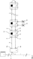
- FIG. 1 shows a schematic block diagram of an automation system. It will be understood by those skilled in the art that the automation system shown is only an example and that all elements, modules, components, participants and units belonging to the automation system can be designed differently but can still fulfill the basic functionalities described here.
- the automation system shown has a higher-level controller 1, which can be implemented, for example, with a programmable logic controller, PLC.
- PLC programmable logic controller
- Such a PLC 1 basically serves to control and regulate the process carried out by the automation system.
- PLCs 1 in automation systems also take on more advanced functions, such as visualization, alarming and recording of all data relating to the process and as such the PLC 1 acts as a human-machine interface.
- a PLC 1 usually has a modular structure and consists of individual components, each of which fulfills a different task.
- a PLC 1 usually consists of a central computing module (with one or more main processors and memory modules) and several modules with inputs and outputs.
- Such modular PLC 1 can be easily expanded by adding modules. It depends on the complexity of the process and the complexity of the structure of the automation system which modules must be integrated into the PLC 1. In today's automation systems, the PLC 1 is usually no longer an independent system, but rather the PLC 1 is connected to the Internet or intranet via appropriate interfaces - not shown here. This means that the PLC 1 is part of a network via which or from which the PLC 1 can receive information, instructions, programming, etc. For example, the PLC 1 can receive information about materials supplied to the process via a connection to a computer located on the intranet or Internet, so that the process can be optimally controlled, for example by knowing their number or nature.
- the PLC 1 is controlled by a user through access from the intranet or Internet.
- a user can use a computer, also called a master computer, to access the PLC 1 and check, change or correct its user programming.
- access to the PLC 1 is possible from one or more remote control centers or control centers.
- the master computers can, if necessary, have visualization devices for displaying process sequences.
- the PLC 1 is connected to automation devices. In order to keep the wiring effort to a minimum, bus systems are used for these connections.
- the PLC 1 is connected to a local bus master 3 of a subordinate local bus system by means of a higher-level bus 2, which in the exemplary embodiment shown here can be a field bus.
- a local bus master 3 of a local bus can be connected to the higher-level bus 2, as in the exemplary embodiment shown here, but also any other participants - not shown here - which are designed for communication with the PLC 1.
- the higher-level bus 2 is connected to the local bus master 3.
- the local bus master 3 has a first interface 4, which is designed in such a way that it communicates with the higher-level bus 2 can be connected.
- the interface 4 can, for example, have a receptacle in the form of a socket and the higher-level bus 2 can have a plug that can be received by the socket.
- the plug and the socket can be, for example, a modular plug and a modular socket, ie each wire of the higher-level bus 2 is electrically or optically connected to a connection in the modular socket.
- an interface 4 should be designed so that the local bus master 3 can be connected electrically or optically to the higher-level bus 2.
- the person skilled in the art is familiar with screw, rotary, click or plug connections, with the help of which an electrical or optical connection can be established.
- a male plug is usually held by a female counterpart.
- This recording usually not only creates the electrical or optical connection, but also ensures that the two parts are mechanically coupled and can only be separated from each other with the application of a certain force.
- the higher-level bus 2 is hard-wired to the interface 4.
- the local bus master 3 in the exemplary embodiment shown here has a further second interface in order to connect the local bus master 3 to the local bus.
- Data bus participants 7a, 7b, ..., 7n are connected to the local bus or form it.
- the local bus is advantageously designed in such a way that a data packet sent by the local bus master 3 is transmitted through all data bus participants 7a, 7b, ..., 7n connected to the local bus and back to the local bus master 3.
- a data bus subscriber 7a, 7b, ..., 7n always only receives a part of the data packet from its upstream data bus subscriber 7a, 7b, ..., 7n.
- the local bus is advantageously designed in a ring-shaped structure. Such local buses can also be referred to as ring bus 6.
- the local bus can alternatively also be designed in a strand-shaped or star-shaped manner or from a combination or mixed form of the aforementioned.
- the data packets are sent and received via the second interface of the local bus master 3.
- the second interface is divided into a first part 5a and a second part 5b.
- the first part 5a of the second interface establishes the downlink in the ring bus 6 and the second part 5b of the second interface establishes the uplink in the ring bus 6.
- the exemplary embodiment shown here has the data bus participants 7a, 7b, ..., 7n in the exemplary embodiment shown here.
- these data bus participants 7a, 7b, ..., 7n each have an interface 8 in order to receive data from an upstream or preceding data bus participant 7a, 7b, ..., 7n.
- data bus participant 7a it receives data from the upstream local bus master 3 via the interface 8.
- the data bus participants 7a, 7b, ..., 7n in the exemplary embodiment shown here each have an interface 9 in order to send data to a downstream or to forward the following data bus participants 7a, 7b, ..., 7n.
- interfaces 8 and 9 serve to propagate data in the downward direction of the ring bus 6, ie away from the local bus master 3.
- the data bus participants 7a, 7b, ..., 7n in this exemplary embodiment also have interfaces 10 and 11 for propagating data in the upward direction of the ring bus 6, ie to the local bus master 3.
- interface 10 is designed to receive data from the downstream or subsequent data bus subscriber 7b and interface 11 is designed to forward data to the upstream or preceding data bus subscriber, here the local bus master 3. So it can also be said that interfaces 9 and 11 are transmitter interfaces, whereas interfaces 8 and 10 are receiver interfaces.
- connections of the interfaces and the PLC 1 or the data bus participants 7a, 7b, ..., 7n are implemented using cables or circuit boards for direct or indirect contacting using electrical contacts.
- Another alternative is that the individual Connections are made wirelessly and the interfaces provide the necessary implementations to the radio standards used.
- the local bus master 3 is therefore arranged decentrally from the data bus participants 7a, 7b, ..., 7n
- the data bus participants 7a, 7b, ..., 7n and the local bus master 3 - which also represents a data bus participant of the ring bus 6 - can also be directly connected to one another.
- contacts of one data bus participant can engage in corresponding receptacles or receiving contacts of a directly adjacent data bus participant in order to establish an electrical connection between the data bus participants so that data can be sent in the downward and upward direction.
- the data bus participants 7a, 7b, ..., 7n can have receptacles on the side facing away from the master and contacts on the side facing the master. If the data bus participants 7a, 7b, ..., 7n are then lined up accordingly, the contacts of one data bus participant 7a, 7b, ..., 7n each engage in the receptacles of the other data bus participant 7a, 7b, ..., 7n and an electrical connection can be created.
- the local bus master 3 then has corresponding contacts on the side which engage in the receptacles of the first data bus subscriber 7a in order to create an electrical connection between the interfaces 5a and 8 or the interfaces 5b and 11.
- the person skilled in the art is also aware of other options, for example pressure contacts, knife and fork contacts, as to how two data bus participants 7a, 7b, ..., 7n arranged directly next to one another can establish an electrical or optical connection.
- the data bus participants 7a, 7b, ..., 7n and the local bus master 3 are to be connected directly to one another, they can also have mechanical receptacles or mechanical fastening means with which the individual data bus participants 7a, 7b, ..., 7n and the local bus master 3 can be connected to each other.
- a data bus subscriber 7a, 7b, ..., 7n can have a projection on one side and an undercut on the other side. If the data bus participants 7a, 7b, ..., 7n are then lined up next to one another, a projection engages in an undercut in the other data bus participant 7a, 7b, ..., 7n, so that a mechanical coupling is created.
- the data bus participants 7a, 7b, ..., 7n can also be arranged on a common receptacle, for example a top-hat rail.
- the data bus participants 7a, 7b, ..., 7n can have corresponding fastening means for fastening to the top-hat rail.
- the data bus participants 7a, 7b, ..., 7n can also have, for example, releasably connectable fastening means with which the data bus participants 7a, 7b, ..., 7n can be attached either to the top-hat rail or to another receptacle.
- the detachably connectable fastening means can be exchangeable and a corresponding fastening means for the desired receptacle can be connected to the data bus participants 7a, 7b, ..., 7n so that they can be fastened to the desired receptacle.
- the data bus participants 7a, 7b, ..., 7n in the in Figure 1 shown embodiment also has a processing unit 12.
- This processing unit 12 can be an arithmetic-logical unit or another type of arithmetic unit with the help of which data can be processed.
- the processing unit 12 is preferably an integral part of the data bus subscriber 7a, 7b, ..., 7n in order to ensure particularly fast and time-synchronized processing of the data.
- the processing unit 12 can also be referred to as the overall circuit of the data bus subscriber. This means that the processing device 12 receives data via inputs 8 and 10 and outputs data on outputs 9 and 11. Furthermore, the processing device 12 can receive or output data from the inputs and outputs 13 and 14. Furthermore, the processing unit 12 has access to a memory - not shown here - of the data bus subscriber 7a, 7b, ..., 7n in which, for example, data, process data or instruction lists are stored.
- the processing unit 12 can be designed to process received data and output data.
- Data to be processed can be received either from an upstream data bus subscriber or from inputs 13 of the data bus subscriber 7a, 7b, ..., 7n.
- the inputs 13 of the data bus subscriber 7a, 7b, ..., 7n can be connected to sensors 15, which send, for example, measurement data, status data, etc.
- Processed data can be output either to a downstream data bus subscriber or to outputs 14 of the data bus subscriber 7a, 7b, ..., 7n.
- the outputs 14 of the data bus subscriber 7a, 7b, ..., 7n can be connected to actuators 16, which, for example, carry out a specific action with the help of the data sent to them. If data processing is also to take place in the upward direction, data can also be received by a downstream data bus participant 7a, 7b, ..., 7n and processed data can be sent to an upstream data bus participant 7a, 7b, ..., 7n.
- the data bus participants 7a, 7b, ..., 7n are only shown with one input 13 and one output 14 and only data bus participant 7b is connected to sensor 15 and actuator 16.
- the data bus participants 7a, 7b, ..., 7n can have a large number of inputs and outputs 13 and 14, and can be connected to a large number of different sensors 15 and actuators 16.
- the feature that characterizes the sensors 15 is that the sensors 15 record data or signals and send them to the data bus participants 7a, 7b, ..., 7n, whereas actuators 16 receive data or signals from the data bus participants 7a, 7b, ..., 7n receive and perform an action based on this data or signal.
- the interfaces 8, 9, 10 and 11 can be integrated in a module unit and the data bus participants 7a, 7b, ..., 7n can be plugged onto this module unit.
- the module units can also be referred to as basic elements of the ring bus 6.
- the ring bus infrastructure is built up by the module units and the data bus participants 7a, 7b, ..., 7n are interchangeable, so that the ring bus 6 can be set up with any data bus participants 7a, 7b, ..., 7n.
- With the help of the module units it is also ensured that even if a data bus participant 7a, 7b, ..., 7n is removed, the communication between the remaining data bus participants 7a, 7b, ..., 7n is not interrupted because the communication via the existing modular units happens.
- the data bus participants 7a, 7b, ..., 7n shown in this exemplary embodiment are also often referred to as I/O modules due to their inputs and outputs 13, 14, which can be connected to sensors 15 or actuators 16. Also If the data bus participants 7a, 7b, ..., 7n are shown as spatially separated from the sensors 15 or actuators 16 in the exemplary embodiment shown here, the sensors 15 or actuators 16 can also be integrated in the I/O module.
- the ring bus 6 shown in the exemplary embodiment shown here is based on cycle frame communication.
- a cycle frame can be defined, for example, as a recurring (cyclic), preferably equidistant time interval in which data can be transferred on the ring bus 6.
- the cycle frame has, for example, at least one start identifier (SOC) and a time range for transmitting data.
- SOC start identifier
- Several start identifiers (SOC) of successive cycle frames are advantageously at a time equidistant from one another.
- the time range mentioned is intended for the transmission of data that can be transmitted within the cycle frame in the form of data packets.
- the start identifier (SOC) and the data packets are transmitted via the ring bus 6 and pass through all data bus participants 7a, 7b, ..., 7n.
- the cycle frame is advantageously initiated by the local bus master 3 in the ring bus 6.
- the start identifier (SOC) is separate, i.e. transferable as an independent symbol or advantageously contained in a start data package (SOC package).
- the cycle frame advantageously also has a trailer.
- the trailer has a variable length and follows the data transmission time range, preferably up to the following start identifier (SOC) of the next cycle frame.
- SOC start identifier
- the trailer advantageously has idle data.
- Each data packet is sent from the local bus master 3 in the downward direction to the first data bus subscriber 7a of the ring bus 6.
- the data bus subscriber 7a then processes the part and then forwards the part to the next data bus subscriber 7b via interface 9, preferably at the same time the first data bus subscriber 7a receives a second part of the data packet, etc.
- the size of the parts of the data packet i.e. the denomination of the data packet, depends on the recording capacity of the data bus participants 7a, 7b, ..., 7n, for example a fixed number of bits, for example 8 bits of the data packet, can be present on the data bus participants 7a, 7b, ..., 7n at the same time for processing.
- the data packet accordingly passes through the data bus participants 7a, 7b, ..., 7n in units, pieces, or parts, for example in parts or symbols of 8 bits.
- the part of the data packet that has been processed by the last data bus participant, in the exemplary embodiment shown here, data bus participant 7n then passes through the ring bus 6 in the upward direction, so that the parts, starting from the last data bus participant 7n, are sent back in the direction of the local bus master 3 through all data bus participants 7a, 7b, ..., 7n upwards.
- the last data bus participant 7n either has a switchable bridge that connects the interface 9 to the interface 10 or a switchable bridge - not shown here - is connected to the last data bus participant 7n, which takes over the function of the parts of the data packet from the interface 9 to route to interface 10.
- the interface 10 of the data bus subscriber 7n can also be connected directly to the interface 5b of the local bus master 3 using a bypass line - not shown here.
- the units of the data packet or data packets can be looped back to the local bus master 3 by the individual data bus participants 7a, 7b, ..., 7n, as in the exemplary embodiment shown here, without any further processing taking place.
- the units of the data packet are processed again in the upward direction, so that the data packet can be processed twice, once in the downward direction to the last data bus subscriber 7n and once in the upward direction to the local bus master 3.
- processing can take place in the upward direction by signal refreshing and/or phase shifting.
- the processing is accomplished with the aid of instruction lists, the instruction lists containing sets of instructions which are sent by the processing unit 12 of the data bus subscriber 7a , 7b, ..., 7n can be executed.
- the instruction lists themselves can be sent to the individual data bus participants 7a, 7b, ..., 7n in an initialization phase by the local bus master 3 or can advantageously be sent to the data bus participants 7a, 7b, ..., 7n during ongoing communication, so that programming of the data bus participants 7a, 7b, ..., 7n takes place without interrupting communication.
- the instruction list index informs the data bus participant which stored instruction list should be used.
- An instruction list index is therefore assigned to an instruction list or vice versa, so that the instruction list to be used can be identified with the help of the instruction list index.
- the instruction list index preferably has a value that is assigned to an instruction list, for example the value indicates a specific instruction list or its storage location.
- the value itself can be the memory address where the instruction list is stored or where at least a first instruction of the instruction list is stored.
- the value can also indicate a memory area in which the corresponding instruction list is stored.
- the value of the instruction list index can also be used, for example, as input to a translation table ( lookup table, LUT).
- the value of the instruction list index is the input value of the conversion table.
- the output value of the translation table may be the memory address of the first instruction in the associated instruction list or otherwise identify the instruction list.
- the conversion table can be stored in software and hardware technology in the form of, for example, logic and a unique conversion from one input value to one Specify the initial value, where the initial value provides an indication of the instruction list to be used. It depends on the conversion table how a connection is established between the instruction list index and the instruction list.
- the instruction list to be used by the data bus subscriber can be clearly identified, ie found, via the instruction list index.
- the instruction list index can be inserted into the data packet before the process data to be processed, so that the data bus participants 7a, 7b, ..., 7n can use the corresponding instruction list according to the order of the process data in the data packet.
- the instruction lists have instructions that are adapted to the order of the process data in the data package.
- the instruction lists can, for example, have a "SKIP" instruction for process data that is not addressed to the data bus subscriber 7a, 7b, ..., 7n, i.e.
- the instruction list for process data that is addressed to the data bus participant 7a, 7b, ..., 7n can have corresponding instructions for processing the process data.
- the processing of the process data can thus be decoupled from the actual position of the process data in the data packet, since the data bus participants are adapted to the order of the process data in the data packet using the instruction lists.
- the local bus master 3 is used in the exemplary embodiment shown here.
- the device responsible for the implementation in the local bus master 3 is in Figure 2 shown.
- FIG. 2 shows a block diagram of an exemplary embodiment of the device according to the invention arranged in the local bus master 3.
- the local bus master 3 is connected to the fieldbus 2 via the interface 4 and to the ring bus 6 via the interface 5.
- the interface 4 can accordingly also be referred to as a fieldbus interface, whereas the Interface 5 can be referred to as a local bus interface.
- Processing units can be connected to the interfaces 4, 5, a first unit 17 can be connected to the fieldbus interface 4, which can also be referred to as a fieldbus core (FBC), and a second unit 19 can be connected to the local bus interface 5, which can also be referred to as Local bus core (LBC) can be called.
- FBC fieldbus core
- LBC Local bus core
- the FBC 17 and the LBC 19 are connected to a data management unit 18 via a parallel bus.
- the parallel bus can be a 32-bit parallel bus and a computing unit, for example a microcontroller, ⁇ C or a processor, which is able to control the FBC 17, the data management unit 18, and the LBC 19, can also be connected to this.
- the data management unit 18 is adapted to transfer first symbols from the FBC 17 to the LBC 19 in a sequence-dependent manner, for example in an unchanged order, so that they can be sent to the ring bus 6 via the local bus interface 5 contained in at least one data packet.
- the first symbols can be process data that was received via the fieldbus 2 via the interface 4 at the FBC 17.
- the LBC 19 can be adapted to generate successive, local bus-compliant data packets for transmitting the process data on the local bus 6 and to insert the process data received from the data management unit 18 into the corresponding data packet.
- the order of the process data can be retained, that is, the process data has the same order in the data packet in the local bus as the order in which the process data was received at the FBC 17 via the fieldbus interface 4.
- 17 fieldbus telegrams from the fieldbus 2 are received at the FBC via the fieldbus interface 4; the fieldbus telegrams have process data in the form of first symbols with a fixed number of bits, for example 8 bits, i.e. 1 byte. These first symbols are arranged in a first order in the fieldbus telegram.
- the data management unit 18 is adapted to copy the process data from the FBC 17 to the LBC 19.
- the LBC 19 is adapted to generate a data packet of the local bus 6, the data packet containing the first symbols of the process data in a second order and the first order and the second order of the symbols matching.
- the data bus participants 7a, 7b, ..., 7n are connected using instruction lists and a Instruction list index set up to evaluate the process data in the data package.
- the instruction list index is placed in front of the process data in the data package.
- the data management unit 18 is adapted to transfer second symbols from the LBC 19 in a sequence-dependent manner, for example unchanged to the FBC 17, so that these can be sent to the fieldbus 2 via the fieldbus interface 4. The second symbols have been received from the local bus 6 at the LBC 19 via the local bus interface 5.
- the local bus interface 5 is divided into two parts, namely parts 5a and 5b, with data being sent in the downward direction to the local bus 6 via part 5a and in the downward direction via part 5b Upward direction can be received from local bus 6.
- the data management unit 18 also has a first and second master interface 18a and 18b.
- the first master interface 18a is connected to a slave interface 17a of the FBC 17. That is, the data management unit 18 and the FBC 17 are in a master-slave relationship, in this case the control comes from the data management unit 18.
- the data management unit 18 therefore reads data from the FBC 17 or writes data into the FBC 17 at a time specified by the data management unit 18.
- the second master interface 18b of the data management unit 18 is connected to a slave interface 19a of the LBC 19.
- the data management unit 18 and the LBC 19 also have a master-slave relationship. This means that the data management unit 18 controls the transfer of data between the FBC 17 and the LBC 19, particularly in both directions.
- the data management unit 18 and the LBC 19 are connected via a further line 25.
- Validity information regarding the transferred symbols can be exchanged between the data management unit 18 and the LBC 19 via this further line 25. This validity information can then be used to delay the sending of the first and second symbols on the fieldbus 2 and the local bus 6, respectively.
- connections between the units are advantageously designed as buses.
- a bus can advantageously be a 32-bit parallel bus.
- the connection can be any other connection that allows the above-described data transfer between the units.
- Figure 3a shows a schematic block diagram of an exemplary embodiment of the device according to the invention implemented in a local bus master 3 of a ring bus 6.
- the first interface 4 of the local bus master 3 receives a fieldbus telegram 20 from the fieldbus 2.
- This fieldbus telegram 20 contains an example of 10 bytes, represented by square boxes , where each box represents 1 byte, i.e. 8 bits. Only the four boxes shown in black, which correspond to 4 bytes, contain first process data 21.
- the other 6 bytes of the fieldbus telegram 20 are information corresponding to the bus protocol used on the fieldbus 2.
- the first process data 21 is also marked here as [1], [ 2], [3] and [4], which symbolizes their order.
- the first process data 21 are selected from the fieldbus telegram 20 by the FBC 17 and stored, for example, in a buffer - not shown here. The selection can consist of the FBC 17 only transferring the process data 21 to a buffer, but ignoring the other bytes of the fieldbus telegram 20.
- the data management unit 18 has a first data transfer unit 22, which reads the process data 21 from the buffer of the FBC 17 via the master-slave interface connection 17a, 18a and then transfers the process data 21 into a buffer - not shown here LBC 19 writes over the master-slave interface connection 18b, 19a.
- the first data transfer unit 22 copies process data 21 from the FBC 17 into the LBC 19. The copying can be done according to instructions and the first data transfer unit 22 can be adapted to precede and/or append further data to the process data 21 and/or between the process data 21 to insert.
- the LBC 19 can be adapted to provide additional data to the process data 21 to prefix and/or append and/or to insert between the process data 21 and/or to change the process data 21.
- the further data from the LBC 19 can be used to convert the process data 21 into a local bus-compliant format, for example into a data packet that can be sent to the local bus 6.
- the process data 21 is preceded by a symbol and a symbol is added to generate a data packet 24 which carries the process data 21.
- the first data transfer unit 22 can be further adapted to communicate the validity of the process data 21 to the LBC 19 after copying the process data 21 into the LBC 19.
- the validity can be communicated via the connection 25. Only when the LBC 19 receives a signal that the copied process data 21 is valid can the LBC 19 send it in the downward direction to the local bus 6 via the local bus interface 5a.
- the validity of the process data 21 is determined, for example, using a CRC or a valid bit.
- parts of the data packet 24 generated by the LBC 19 can be sent to the local bus 6 even before the validity display.
- the parts of the data packet 24 are the data bus participants 7a, 7b, ..., 7n - as in Figure 1 shown - run through successively, ie at any given time only a part of the data packet 24 is sent by the local bus master 3, which is then forwarded by the individual data bus participants 7a, 7b, ..., 7n.
- the LBC 19 can send the part of the data packet 24 to the local bus 6 that contains the process data or other information before the validity display.
- the LBC 19 can already send the attached symbol as the first part of the data packet 24 to the local bus 6.
- the first data transfer unit 22 thus copies process data 21 from the fieldbus 2 to the local bus 6.
- the order [1], [2], [3], [4] of the process data 21 is retained, that is, the order of the process data 21 is the same in the fieldbus telegram 20 and in the data packet 24 of the local bus 6.
- the Process data 21 is copied bus-neutrally, that is, without the bus-specific information with which the process data 21 is received. In the exemplary embodiment shown here, the preceding two symbols and the added four symbols of the fieldbus telegram 20 are not copied.
- Figure 3b shows a schematic block diagram of an exemplary embodiment of the device according to the invention implemented in a local bus master 3 of a ring bus 6.
- the second interface 5b of the local bus master 3 receives a data packet 26.
- the data packet 26 contains an example of 6 bytes, represented by square boxes, each Box represents 1 byte, i.e. 8 bits. Only the four boxes shown in black, which correspond to 4 bytes, contain second process data 27.
- the other 2 bytes of the data packet 26 are information corresponding to the bus protocol used on the local bus 6.
- the second process data 27 are also marked here as [1'], [2'], [3'] and [4'], which symbolizes their order.
- the second process data 27 can be based on the first process data 21 - as in Figure 3a shown - and can represent the process data 21 after it has passed through, ie its processing, through the local bus 6.
- the process data 27 are selected from the data packet 26 by the LBC 19 and stored, for example, in a buffer - not shown here.
- the selection can consist of the LBC 19 only transferring the process data 27 to a buffer, but ignoring the other bytes of the data packet 26.
- the data management unit 18 has a second data transfer unit 23, which reads the process data 27 from the buffer of the LBC 19 via the master-slave interface connection 18b, 19a and then the process data 27 into a buffer of the FBC 17 via the master -Slave interface connection 17a, 18a writes. Ie the second data transfer unit 23 copies process data 27 from the LBC 19 into the FBC 17. The copying can be done according to instructions and the second data transfer unit 23 can be adapted to precede and/or append further data to the process data 27 and/or between the process data 27 to insert and/or change the process data. Alternatively or additionally, the FBC 17 can be adapted to precede and/or append further data to the process data 27 and/or between them Insert process data 27.
- the further data from the FBC 17 can be used to convert the process data 27 into a fieldbus-compliant format, for example in Fedbus telegram 28 of the fieldbus 2.
- the process data 27 is preceded by two symbols and four symbols are added to generate one Fieldbus telegram 28, which carries the process data 27.
- the person skilled in the art is aware that even if only a specific number of symbols are prefixed and appended to the process data 27, this can also be any number of symbols, with the number depending solely on the fieldbus telegram format used, which is on the fieldbus 2 is used.
- the second data transfer unit 23 can be further adapted to copy only part of the process data 27 into the FBC 17 and to copy the remaining process data 27 only after receiving a validity indication from the LBC 19 via the connection 25. This allows the second data transfer unit 23 to control the time at which the fieldbus telegram 28 is sent by the FBC 17, because this is always sent directly when the fieldbus telegram 28 is completely filled with process data 27. If this is not yet the case, no fieldbus telegram 28 will be sent. This allows control between the second data transfer unit 23 and the FBC 17 without the need for a further connection.
- the validity of the process data 27 is determined using a CRC.
- the components of the device according to the invention described in the described exemplary embodiment as separate units, modules or interfaces can be implemented as separate hardware or can be integrated on the same semiconductor chip and their function can be implemented by hardware consisting of logic gates.
- the units, modules, or interfaces can be implemented on an FPGA/ASIC.
Description
Die Erfindung betrifft im Allgemeinen eine Vorrichtung zum Verbinden eines Feldbusses mit einem Lokalbus und im Speziellen einen Busumsetzer von Daten aus einem Datenstrom eines Feldbusses in einen Datenstrom eines Lokalbusses.The invention generally relates to a device for connecting a fieldbus to a local bus and in particular to a bus converter of data from a data stream of a fieldbus into a data stream of a local bus.
Vorrichtungen zum Verbinden zweier Bussysteme werden zumeist in Automatisierungsanlagen verwendet.Devices for connecting two bus systems are mostly used in automation systems.
Automatisierungsanlagen werden insbesondere zur Steuerung von industriellen Anlagen, Gebäuden sowie von Verkehrsmitteln eingesetzt. Für die Steuerung einer Automatisierungsanlage sind zumeist mehrere Sensoren und Aktoren notwendig. Diese überwachen und steuern den von der Anlage ausgeführten Prozess. Die unterschiedlichen Sensoren und Aktoren einer Automatisierungsanlage werden dabei häufig auch als Automatisierungsgeräte bezeichnet.Automation systems are used in particular to control industrial systems, buildings and means of transport. Several sensors and actuators are usually necessary to control an automation system. These monitor and control the process carried out by the system. The different sensors and actuators in an automation system are often referred to as automation devices.
Diese Automatisierungsgeräte können entweder direkt mit einer Steuerung der Automatisierungsanlage verbunden werden, oder können zunächst mit Ein- und Ausgangsmodulen, die häufig auch als E/A-Module bezeichnet werden, verbunden werden. Diese können dann wiederum direkt mit der Steuerung verbunden werden. Die Automatisierungsgeräte können dabei entweder direkt in den E/A-Modulen integriert sein oder können mit diesen über Kabel oder kabellos verbunden sein.These automation devices can either be connected directly to a controller of the automation system, or can first be connected to input and output modules, which are often also referred to as I/O modules. These can then be connected directly to the controller. The automation devices can either be integrated directly into the I/O modules or can be connected to them via cable or wirelessly.
Die Steuerung einer Automatisierungsanlage wird in der Regel mit Hilfe einer oder mehrerer speicherprogrammierbaren Steuerungen, SPS, bewerkstelligt. Die SPSs können dabei hierarchisch oder dezentral in einer Automatisierungsanlage angeordnet sein. Dabei gibt es bei den SPS unterschiedliche Leistungsklassen, so dass diese je nach Rechen- und Speicherkapazität unterschiedliche Steuerungen und Regelungen übernehmen können. Eine SPS hat im einfachsten Fall Eingänge, Ausgänge, ein Betriebssystem (Firmware) und eine Schnittstelle, über die ein Anwenderprogramm geladen werden kann. Das Anwenderprogramm legt fest, wie die Ausgänge in Abhängigkeit von den Eingängen geschaltet werden sollen. Dabei können die Eingänge und Ausgänge mit den Automatisierungsgeräten und/oder den E/A-Modulen verbunden werden und anhand der im Anwenderprogramm hinterlegten Logik kann der Prozess, der von der Automatisierungsanlage durchgeführt wird, überwacht beziehungsweise gesteuert werden. Dabei wird die Überwachung des Prozesses durch die Sensoren bewerkstelligt und die Steuerung des Prozesses durch die Aktoren. Die Steuerung kann auch als zentrale Steuerung oder Zentraleinheit bezeichnet werden und übernimmt zumindest für ein mit der Steuerung verbundenes Automatisierungsgerät oder E/A-Modul die Steuerung.The control of an automation system is usually accomplished with the help of one or more programmable logic controllers, PLCs. The PLCs can be arranged hierarchically or decentrally in an automation system. There are different performance classes for the PLCs, so that they can take on different controls and regulations depending on the computing and storage capacity. In the simplest case, a PLC has inputs and outputs Operating system (firmware) and an interface through which a user program can be loaded. The user program determines how the outputs should be switched depending on the inputs. The inputs and outputs can be connected to the automation devices and/or the I/O modules and the process carried out by the automation system can be monitored or controlled using the logic stored in the user program. The process is monitored by the sensors and the process is controlled by the actuators. The control can also be referred to as a central control or central unit and takes over control of at least one automation device or I/O module connected to the control.
Allerdings ist das direkte Verbinden der Automatisierungsgeräte mit der zumindest einen Steuerung oder der E/A-Module mit der zumindest einen Steuerung in Form einer parallelen Verdrahtung, d.h. von jedem Automatisierungsgerät oder jedem E/A-Modul wird je eine Leitung zur übergeordneten Steuerung verlegt, sehr aufwendig. Gerade bei steigendem Automatisierungsgrad einer Automatisierungsanlage wächst der Verkabelungsaufwand bei paralleler Verdrahtung. Dies ist mit großem Aufwand bei der Projektierung, Installation, Inbetriebnahme und Wartung verbunden.However, the direct connection of the automation devices to the at least one controller or the I/O modules to the at least one controller is in the form of parallel wiring, i.e. one line is laid from each automation device or each I/O module to the higher-level controller. very complex. Especially as the degree of automation of an automation system increases, the cabling effort increases with parallel wiring. This involves a lot of effort in project planning, installation, commissioning and maintenance.
Daher werden heutzutage in der Automatisierungstechnik zumeist Bussysteme eingesetzt, mit denen die Automatisierungsgeräte beziehungsweise die E/A-Module an die Steuerung angeschlossen werden können. Derartige Teilnehmer eines Bussystems werden auch als Busteilnehmer bezeichnet. Weil auf dem Bussystem Daten ausgetauscht werden, werden die Busteilnehmer auch häufig als Datenbusteilnehmer bezeichnet. Um die Anbindung der einzelnen Automatisierungsgeräte beziehungsweise der E/A-Module mit dem Bussystem noch weiter zu vereinfachen, werden heutzutage häufig einzelne Gruppen von Automatisierungsgeräten beziehungsweise E/A-Modulen mit Hilfe eines spezialisierten Lokalbusses zunächst untereinander zu einem Lokalbussystem verbunden und anschließend wird zumindest ein Teilnehmer dieses Lokalbusses mit dem Bussystem verbunden, welches mit der Steuerung verbunden ist. Dabei kann sich das Lokalbussystem von dem Bussystem unterscheiden, welches eingesetzt wird, um die Verbindung mit der Steuerung zu realisieren.Therefore, nowadays bus systems are mostly used in automation technology with which the automation devices or the I/O modules can be connected to the control. Such participants in a bus system are also referred to as bus participants. Because data is exchanged on the bus system, the bus participants are often referred to as data bus participants. In order to further simplify the connection of the individual automation devices or I/O modules to the bus system, individual groups of automation devices or I/O modules are now often first connected to each other to form a local bus system using a specialized local bus and then at least one Participants of this local bus are connected to the bus system, which is connected to the controller. The local bus system can differ from the bus system that is used to establish the connection to the controller.
Der mit dem Bussystem der Steuerung verbundene Teilnehmer einer Gruppe von Lokalbusteilnehmern wird häufig auch als Lokalbusmaster bezeichnet. Alternativ wird auch die Bezeichnung Kopfstation des Lokalbussystems verwendet. Dieser Lokalbusmaster kann gegenüber anderen Lokalbusteilnehmer weitere Logiken, Schaltungen oder Funktionalitäten beinhalten, die zur Anbindung an das Bussystem der Steuerung notwendig sind. Auch kann der Lokalbusmaster selbst eine SPS beinhalten. Auch kann dieser Teilnehmer Logiken und Schaltungen zur Umsetzung zwischen den zwei Bussystemen aufweisen. Der Lokalbusmaster kann daher auch als Gateway oder Busumsetzer ausgebildet sein und sorgt für eine Umsetzung der im Format des einen Bussystems vorliegenden Daten in das Format des Lokalbussystems und umgekehrt, wie zum Beispiel in
Die zum Einsatz kommenden Lokalbusse sind zumeist auf die speziellen Einsatzerfordernisse der Automatisierungsgeräte beziehungsweise E/A-Module abgestimmt oder berücksichtigen deren spezielle Hardwareausgestaltung. Dabei bilden die Gruppen an Automatisierungsgeräten beziehungsweise E/A-Modulen des Lokalbussystems zumeist eine Untergruppe der Automatisierungsanlage zur Ausführung einer speziellen Aufgabe in dem von der Automatisierungsanlage ausgeführten Prozess. Die auf den Bussen ausgetauschten Daten für den Prozess werden auch häufig als Lokalbusdaten oder Prozessdaten bezeichnet, weil diese Daten Informationen zur Regelung beziehungsweise Steuerung des von der Automatisierungsanlage ausgeführten Prozesses beinhaltet. Diese Daten können dabei unter anderem Messdaten, Steuerungsdaten, Zustandsdaten und/oder andere Informationen umfassen. Entsprechend des verwendeten Busprotokolls können diesen Daten andere Daten vorangestellt (engl. Header) oder angehängt (engl. Tail) sein. Diese anderen Daten können Informationen bezüglich der Daten beinhalten, oder Informationen bezüglich einer internen Kommunikation auf dem Lokalbus beinhalten. Hierbei ist eine Vielzahl von unterschiedlichen Informationen bekannt, die entsprechend des verwendeten Busprotokolls den Daten vorangestellt oder angefügt werden können. Die an einen Lokalbus angeschlossenen Lokalbusteilnehmer können auch als Datenbusteilnehmer bezeichnet werden, weil diese Daten auf dem Lokalbus austauschen. Ein Datenbusteilnehmer dient dabei zum Steuern oder Überwachen eines Prozesses, insbesondere durch eine Ausgabe von Steuersignalen z.B. an Aktoren und/oder durch einen Empfang von Messsignalen z.B. von Sensoren. Der Datenbusteilnehmer setzt die Steuersignale und/oder Messsignale in Daten für den Lokalbus um oder umgekehrt.The local buses used are usually tailored to the specific application requirements of the automation devices or I/O modules or take their special hardware design into account. The groups of automation devices or I/O modules of the local bus system usually form a subgroup of the automation system for carrying out a specific task in the process carried out by the automation system. The data exchanged on the buses for the process is also often referred to as local bus data or process data because this data contains information for regulating or controlling the process carried out by the automation system. This data can include, among other things, measurement data, control data, status data and/or other information. Depending on the bus protocol used, this data can be preceded by other data ( header ) or appended ( tail ). This other data may include information regarding the data, or may include information regarding internal communication on the local bus. A variety of different pieces of information are known, which can be placed in front of or added to the data depending on the bus protocol used. The local bus participants connected to a local bus can also be referred to as data bus participants because they exchange data on the local bus. A data bus participant is used to control or monitor a process, in particular by outputting control signals, for example to actuators and/or by receiving measurement signals, for example from sensors. The data bus participant converts the control signals and/or measurement signals into data for the local bus or vice versa.
Ein Ringbus ist dabei eine spezialisierte Form eines Lokalbusses, wie zum Beispiel aus
In einem Ringbus wird ein Datenpaket von einem zum anderen Datenbusteilnehmer weitergegeben. Dabei empfängt zu jeder gegebenen Zeit ein Datenbusteilnehmer von seinem vorgelagerten Datenbusteilnehmer immer nur einen Teil des Datenpakets. Wenn die in diesem Teil enthaltenen Daten vom Datenbusteilnehmer verarbeitet worden sind, wird der Teil an den nachgelagerten Datenbusteilnehmer weitergeleitet und gleichzeitig wird von dem vorgelagerten Datenbusteilnehmer ein neuer Teil des Datenpakets empfangen. Auf diese Weise passieren alle Teile des Datenpakets sequentiell alle Datenbusteilnehmer.In a ring bus, a data packet is passed on from one data bus participant to another. At any given time, a data bus subscriber only receives a part of the data packet from its upstream data bus subscriber. When the data contained in this part has been processed by the data bus subscriber, the part is forwarded to the downstream data bus subscriber and at the same time a new part of the data packet is received by the upstream data bus subscriber. In this way, all parts of the data packet pass sequentially through all data bus participants.
In den bekannten Ringbussystemen oder auch anderen Lokalbussystemen werden Busumsetzer verwendet, die die Datenströme von der Steuerung in ein lokalbuskonformes Format umsetzen. Dabei werden zumeist leistungsstarke Controller verwendet, die die Daten stammend von der Steuerung derart umsortieren, dass diese entsprechend der Reihenfolge der Datenbusteilnehmer am Lokalbus in einem lokalbuskonformen Format vorliegen. D.h. die Reihenfolge der Daten nach der Umsortierung entspricht der Reihenfolge in der die Datenbusteilnehmer am Lokalbus angeordnet sind. Durch diese Umsortierung kann in derartigen Bussystemen eine Adressierung entfallen, weil die Daten entsprechend der physikalischen Position der Datenbusteilnehmer im Lokalbus angeordnet sind. Zum Beispiel werden die Daten, die an den ersten Datenbusteilnehmer gerichtet sind, an die erste Stelle im lokalbuskonformen Format gesetzt, die Daten die, an den zweiten Datenbusteilnehmer im Lokalbus gerichtet sind, werden an die zweite Stelle im lokalbuskonformen Format gesetzt usw. Damit diese Umsetzung und insbesondere die Umsortierung ohne größere Verzögerungen stattfindet, werden in bekannten Systemen zumeist leistungsstarke, hochgetaktete Controller eingesetzt. Aber auch mit diesen leistungsstarken Controllern kann eine Verzögerung nur bis zu einem gewissen Grad minimiert werden. Leistungsstarke Controller bringen auch mehrere Nachteile mit sich, die Controller müssen zumeist aktiv gekühlt werden, haben eine hohe Leistungsaufnahme und sind kostspielig.In the known ring bus systems or other local bus systems, bus converters are used that convert the data streams from the controller into a local bus-compliant format. This usually involves powerful controllers used, which rearrange the data coming from the controller in such a way that it is available in a local bus-compliant format according to the order of the data bus participants on the local bus. This means that the order of the data after the re-sorting corresponds to the order in which the data bus participants are arranged on the local bus. This rearrangement means that addressing can be omitted in such bus systems because the data is arranged in the local bus according to the physical position of the data bus participants. For example, the data that is directed to the first data bus participant is placed in the first position in the local bus-compliant format, the data that is directed to the second data bus participant in the local bus is placed in the second position in the local bus-compliant format, etc. This implementation and in particular the re-sorting takes place without major delays, powerful, high-clocked controllers are usually used in known systems. But even with these powerful controllers, lag can only be minimized to a certain extent. Powerful controllers also have several disadvantages: the controllers usually have to be actively cooled, have high power consumption and are expensive.
Die
Aufgabe der vorliegenden Erfindung ist es daher, eine Vorrichtung und ein entsprechendes Verfahren bereitzustellen, mit dem die Umsetzung von Daten von einem Feldbus in einen Lokalbus und insbesondere in einen Ringbus nahezu verzögerungsfrei geschieht und die Umsetzung ohne komplexe Hardware auskommt.The object of the present invention is therefore to provide a device and a corresponding method with which the conversion of data from a fieldbus to a local bus and in particular to a ring bus occurs almost without delay and the implementation does not require complex hardware.
Diese Aufgabe wird mit der Vorrichtung und dem Verfahren entsprechend der unabhängigen Ansprüche gelöst. Vorteilhafte Ausführungsformen sind in den Unteransprüchen beschrieben.This task is solved with the device and the method according to the independent claims. Advantageous embodiments are described in the subclaims.
Dabei weist die erfindungsgemäße Vorrichtung, die auch als Busumsetzer oder Gateway bezeichnet werden kann, eine erste Einheit auf, die mit einem Feldbus verbindbar ist und die angepasst ist zum Senden und zum Empfangen von Daten über den Feldbus. Ein Feldbus kann dabei jeder Bus sein, der in einer Automatisierungsanlage eingesetzt werden kann und mit dessen Hilfe eine Verbindung zur Steuerung, beispielsweise der SPS, hergestellt werden kann. Dabei kann die Verbindung zur Steuerung auch über mehrere unterschiedliche Feldbusse hergestellt werden, die Gesamtheit der Verbindung zwischen erfindungsgemäßer erster Einheit und Steuerung soll dabei als ein Feldbus verstanden werden auch wenn diese Verbindung aus mehreren unterschiedlichen Feldbussen besteht. Die erste Einheit ist erfindungsgemäß angepasst, um mit dem Feldbus verbunden zu werden. Hierzu kann die erste Einheit eine für den Feldbus ausgelegte Schnittstelle aufweisen. Die Schnittstelle kann kabelgebunden oder kabellos eine Verbindung mit dem Feldbus herstellen. Über die Schnittstelle der ersten Einheit beziehungsweise über die erste Einheit kann ein Datenstrom von dem Feldbus empfangen werden und ein Datenstrom auf den Feldbus ausgegeben werden. Die erste Einheit kann auf Grund ihrer Konnektivität zum Feldbus auch als Feldbuscore (FBC) bezeichnet werden. Der FBC kann ausgebildet sein als eine individuelle arithmetische-logische Einheit, als Rechenkern, oder als Rechenschaltung die als digitale Logik ausgestaltet ist, die insbesondere zumindest als ein Teil eines Halbleiterchips ausgebildet ist. Der FBC kann in einem anwendungsspezifischen integrierten Schaltkreis (engl. ASIC), oder in einer Feld programmierbaren (Logik-)Gatter-Anordnung (engl. FPGA), oder in einer anderen programmierbare Schaltung (engl. PLD), oder einer diskreten Gatter oder Transistorlogik implementiert sein.The device according to the invention, which can also be referred to as a bus converter or gateway, has a first unit which can be connected to a fieldbus and which is adapted to send and receive data via the fieldbus. A fieldbus can be any bus that can be used in an automation system and can be used to establish a connection to the controller, for example the PLC. The can Connection to the control can also be established via several different fieldbuses, the entire connection between the first unit according to the invention and the control should be understood as a fieldbus, even if this connection consists of several different fieldbuses. The first unit is adapted according to the invention to be connected to the fieldbus. For this purpose, the first unit can have an interface designed for the fieldbus. The interface can establish a connection to the fieldbus in a wired or wireless manner. A data stream can be received from the fieldbus and a data stream can be output to the fieldbus via the interface of the first unit or via the first unit. The first unit can also be referred to as a fieldbus core (FBC) due to its connectivity to the fieldbus. The FBC can be designed as an individual arithmetic-logical unit, as a computing core, or as a computing circuit that is designed as digital logic, which is in particular designed as at least part of a semiconductor chip. The FBC can be implemented in an application-specific integrated circuit (ASIC), or in a field programmable (logic ) gate array (FPGA), or in another programmable circuit ( PLD ), or in a discrete gate or transistor logic be implemented.
Des Weiteren weist die erfindungsgemäße Vorrichtung auch eine zweite Einheit auf, die mit einem Lokalbus, insbesondere einem Ringbus verbindbar ist und die angepasst ist zum Senden und zum Empfangen von Daten über den Lokalbus in Form zumindest eines Datenpakets. Die Datenpakete können auch als Telegramme bezeichnet werden. Ein Datenpaket weist beispielsweise Header, Payload und vorteilhafterweise eine Prüfsumme auf. Ein Datenpaket ist vorteilhafterweise ein Kommunikationsdatenpaket oder ein Prozessdatenpaket.Furthermore, the device according to the invention also has a second unit which can be connected to a local bus, in particular a ring bus, and which is adapted to send and receive data via the local bus in the form of at least one data packet. The data packets can also be referred to as telegrams. A data packet has, for example, header, payload and advantageously a checksum. A data packet is advantageously a communication data packet or a process data packet.
Ein Kommunikationsdatenpaket enthält keine Prozessdaten. Vorteilhafterweise enthält ein Kommunikationsdatenpaket Daten insbesondere zum Programmieren und/oder zum Steuern und/oder zum Überwachen und/oder zum Identifizieren zumindest eines Datenbusteilnehmers. Vorteilhafterweise weist das Kommunikationsdatenpaket eine Adresse auf, die mindestens einem Datenbusteilnehmer zugeordnet ist. Vorzugsweise ist der Datenbusteilnehmer eingerichtet, die Adresse auszuwerten.A communication data packet does not contain any process data. A communication data packet advantageously contains data, in particular for programming and/or for controlling and/or for monitoring and/or for identifying at least one data bus participant. The communication data packet advantageously has an address that is assigned to at least one data bus subscriber. The data bus subscriber is preferably set up to evaluate the address.
Ein Prozessdatenpaket weist Prozessdaten auf, die von den Datenbusteilnehmern des Lokalbusses gesendet und/oder empfangen werden. Vorteilhafterweise weist das Prozessdatenpaket keine Adresse zur Übertragung der Prozessdaten an einen oder von einem Datenbusteilnehmer im Lokalbus auf. In dem Prozessdatenpaket sind die Prozessdaten beispielsweise derart angeordnet, dass Datenbusteilnehmer auf Grund der jeweiligen Position der Prozessdaten in dem Prozessdatenpaket, beispielsweise ein oder mehrere Bits innerhalb eines zugeordneten zusammenhängenden Datenblocks (1 Byte), diejenigen dem jeweiligen Datenbusteilnehmer zugehörigen Prozessdaten erkennen können. Vorteilhafterweise weist das Prozessdatenpaket eine Kennung (IDE) auf, die dem Typ des Datenpakets, also dem Prozessdatenpaket zugeordnet und durch den Datenbusteilnehmer identifizierbar ist. Die Prozessdaten können auch als Lokalbusdaten bezeichnet werden.A process data packet has process data that is sent and/or received by the data bus participants of the local bus. Advantageously, the process data packet does not have an address for transmitting the process data to or from a data bus participant in the local bus. In the process data packet, the process data are arranged, for example, in such a way that data bus participants can recognize the process data belonging to the respective data bus participant based on the respective position of the process data in the process data packet, for example one or more bits within an assigned coherent data block (1 byte). The process data packet advantageously has an identifier (IDE) which is assigned to the type of data packet, i.e. the process data packet, and can be identified by the data bus participant. The process data can also be referred to as local bus data.
Die Protokolle, die auf dem Feldbus und dem Lokalbus verwendet werden, können sich unterscheiden, so dass das feldbuskonforme Format nicht ohne Umsetzung auf den Lokalbus gesendet werden kann sowie umgekehrt das lokalbuskonforme Format nicht ohne Umsetzung auf den Feldbus gesendet werden kann.The protocols used on the fieldbus and the local bus can differ, so that the fieldbus-compliant format cannot be sent to the local bus without conversion and, conversely, the localbus-compliant format cannot be sent to the fieldbus without conversion.
Die zweite Einheit ist erfindungsgemäß angepasst, um mit dem Lokalbus verbunden zu werden. Hierzu kann die zweite Einheit eine für den Lokalbus ausgelegte Schnittstelle aufweisen. Die Schnittstelle kann kabelgebunden oder kabellos eine Verbindung mit dem Lokalbus herstellen. Über die Schnittstelle der zweiten Einheit beziehungsweise über die zweite Einheit kann ein Datenpaket auf den Lokalbus gesendet werden und ein Datenpaket von dem Lokalbus empfangen werden. Die zweite Einheit kann auf Grund ihrer Konnektivität zum Lokalbus auch als Lokalbuscore (LBC) bezeichnet werden. Der LBC kann ausgebildet sein als eine individuelle arithmetische-logische Einheit, als Rechenkern, oder als Rechenschaltung die als digitale Logik ausgestaltet ist, die insbesondere zumindest als ein Teil eines Halbleiterchips ausgebildet ist. Der LBC kann in einem ASIC, oder in einem FPGA, oder in einer anderen PLD, oder einer diskreten Gatter oder Transistorlogik implementiert sein.The second unit is adapted according to the invention to be connected to the local bus. For this purpose, the second unit can have an interface designed for the local bus. The interface can connect to the local bus in a wired or wireless manner. A data packet can be sent to the local bus and a data packet can be received from the local bus via the interface of the second unit or via the second unit. The second unit can also be referred to as a local bus core (LBC) due to its connectivity to the local bus. The LBC can be designed as an individual arithmetic-logical unit, as a computing core, or as a computing circuit that is designed as digital logic, which is in particular designed as at least part of a semiconductor chip. The LBC can be implemented in an ASIC, or in an FPGA, or in another PLD, or discrete gate or transistor logic.
Die erfindungsgemäße Vorrichtung weist auch eine Datenverwaltungseinheit auf die mit der ersten und zweiten Einheit verbunden ist. Die Datenverwaltungseinheit kann auch als Managementeinheit (MU) bezeichnet werden, dabei kann diese entsprechend ihrer Richtung in der diese fungiert als Feldbus-Managementeinheit (FMU) oder Lokalbus-Managementeinheit (LMU) bezeichnet werden. Die Verbindung kann vorteilhafterweise ein paralleler Bus zwischen den Einheiten sein, der beispielsweise als ein 32-bit Parallelbus ausgestaltet ist. Die Datenverwaltungseinheit ist angepasst zum reihenfolgenabhängigen Transferieren von ersten Symbolen aus Daten empfangen über die erste Einheit (FBC) in die zweite Einheit (LBC). Reihenfolgenabhängig in diesem Zusammenhang meint, dass Symbole entsprechend ihrer Reihenfolge empfangen von der ersten Einheit in die zweite Einheit transferiert werden. Die Reihenfolge richtet sich also nach den ankommenden Symbolen. Beispielsweise können die Symbole empfangen über den Feldbus reihenfolgerichtig in die zweite Einheit transferiert werden. Beispielsweise wird dabei die Reihenfolge der über den Feldbus empfangenen Symbole nicht geändert oder überwiegend nicht geändert, d.h. die Symbole werden in der Reihenfolge in der sie auf dem Feldbus empfangen werden auch in die zweite Einheit transferiert. Es kann auch gesagt werden, dass keine Umsortierung stattfindet, weil die Reihenfolge der Symbole beibehalten wird. Es kann auch davon gesprochen werden, dass die Symbole eins zu eins transferiert werden. Dabei kann es sich bei den transferierten Symbolen um Prozessdaten handeln, die von der Steuerung über den Feldbus in einem feldbuskonformen Format empfangen wurden. Dabei kann das feldbuskonforme Format Prozessdaten sowie andere Daten, die den Prozessdaten vorangestellt, angefügt, oder superpositioniert sind, aufweisen. Dabei sind die anderen Daten beispielsweise busspezifisch und die Prozessdaten sind busneutral. Zumeist werden in einem feldbuskonformen Format den Prozessdaten andere Daten vorangestellt, die als Kopfteil bezeichnet werden können und die zumeist der Adressierung und Steuerung dienen. Den Prozessdaten können auch weitere andere Daten angefügt sein, die zur Fehlererkennung genutzt werden können. Die Prozessdaten sind ein Bestandteil des Nutzdatenteils (engl. Payload) des feldbuskonformen Formats. Die Prozessdaten sind dazu ausgelegt an den Datenbusteilnehmern des Lokalbusses eine Steuerung, Regelung oder anderweitige Reaktion hervorzurufen. Über den Feldbus können beispielsweise Feldbustelegramme empfangen werden, in denen die Prozessdaten in Form von Symbolen mit einer festen Anzahl von Bits enthalten sind und wobei die Symbole in einer ersten Reihenfolge im Feldbustelegramm angeordnet sind. Die Datenverwaltungseinheit kann dabei angepasst sein, die Symbole aus dem Feldbustelegramm in den LBC zu transferieren und zwar in eine zweite Reihenfolge. Vorzugsweise stimmen die erste und zweiteThe device according to the invention also has a data management unit which is connected to the first and second units. The data management unit can also be referred to as a management unit (MU), but this can be done accordingly The direction in which it functions is referred to as a fieldbus management unit (FMU) or local bus management unit (LMU). The connection can advantageously be a parallel bus between the units, which is designed, for example, as a 32-bit parallel bus. The data management unit is adapted for the order-dependent transfer of first symbols from data received via the first unit (FBC) into the second unit (LBC). Sequence dependent in this context means that symbols are transferred from the first unit to the second unit according to the order they are received. The order depends on the incoming symbols. For example, the symbols received via the fieldbus can be transferred to the second unit in the correct order. For example, the order of the symbols received via the fieldbus is not changed or predominantly not changed, ie the symbols are also transferred to the second unit in the order in which they are received on the fieldbus. It can also be said that no reordering occurs because the order of the symbols is maintained. It can also be said that the symbols are transferred one to one. The transferred symbols can be process data that was received from the controller via the fieldbus in a fieldbus-compliant format. The fieldbus-compliant format can have process data as well as other data that is preceded, appended or superpositioned to the process data. For example, the other data is bus-specific and the process data is bus-neutral. In most cases, in a fieldbus-compliant format, the process data is preceded by other data, which can be referred to as the header and which is usually used for addressing and control. Other data that can be used to detect errors can also be attached to the process data. The process data is part of the payload part of the fieldbus -compliant format. The process data is designed to trigger a control, regulation or other reaction on the data bus participants of the local bus. For example, fieldbus telegrams can be received via the fieldbus in which the process data is contained in the form of symbols with a fixed number of bits and the symbols are arranged in a first order in the fieldbus telegram. The data management unit can be adapted to transfer the symbols from the fieldbus telegram to the LBC, specifically in a second order. Preferably the first and second are correct
Reihenfolge der Symbole dabei überein. Die Datenverwaltungseinheit ist erfindungsgemäß angepasst, nur die Prozessdaten zu transferieren. D.h. bereits die erste Einheit ist angepasst, die Prozessdaten aus dem feldbuskonformen Format beziehungsweise dem Feldbustelegramm zu selektieren. Die Datenverwaltungseinheit kann ausgebildet sein als eine individuelle arithmetische-logische Einheit, als Rechenkern, oder als Rechenschaltung die als digitale Logik ausgestaltet ist, die insbesondere zumindest als ein Teil eines Halbleiterchips ausgebildet ist. Die Datenverwaltungseinheit kann in einem ASIC, oder in einem FPGA, oder in einer anderen PLD, oder einer diskreten Gatter oder Transistorlogik implementiert sein. Der FBC, der LBC und die Datenverwaltungseinheit können auch in einem ASIC, oder in einem FPGA, oder in einer PLD, oder in einer diskreten Gatter oder Transistorlogik gemeinsam implementiert sein. Insbesondere nach der Transferierung kann mittels einer Manipulationseinheit vorgesehen sein, die Prozessdaten durch den Lokalbusmaster gezielt zu ändern. Hierzu weist der Lokalbusmaster vorteilhafterweise Instruktionen auf, die ein Ändern der Prozessdaten bewirken.The order of the symbols corresponds. According to the invention, the data management unit is adapted to only transfer the process data. This means that the first unit is already adapted to select the process data from the fieldbus-compliant format or the fieldbus telegram. The data management unit can be designed as an individual arithmetic-logical unit, as a computing core, or as a computing circuit which is designed as digital logic, which is in particular designed as at least part of a semiconductor chip. The data management unit may be implemented in an ASIC, or in an FPGA, or in another PLD, or discrete gate or transistor logic. The FBC, the LBC and the data management unit can also be implemented together in an ASIC, or in an FPGA, or in a PLD, or in discrete gate or transistor logic. In particular, after the transfer, a manipulation unit can be used to specifically change the process data by the local bus master. For this purpose, the local bus master advantageously has instructions that cause the process data to be changed.
Nachdem die ersten Symbole in den LBC transferiert wurden und ein Datenpaket erzeugt wurde, der die transferierten Symbole trägt, kann dieses Datenpaket in beispielsweise Teilen von 8 Bits, also 1 Byte, auf den Lokalbus gesendet werden und die einzelnen Teile des Datenpakets können sukzessive die Datenbusteilnehmer des Lokalbusses durchlaufen. D.h. zu jeder gegebenen Zeit empfängt ein Datenbusteilnehmer von seinem vorgelagerten Datenbusteilnehmer immer nur einen Teil des Datenpakets. Wenn die in diesem Teil enthaltenen Prozessdaten vom Datenbusteilnehmer verarbeitet worden sind, wird der Teil an den nachgelagerten Datenbusteilnehmer weitergeleitet und gleichzeitig wird von dem vorgelagerten Datenbusteilnehmer ein neuer Teil des Datenpakets empfangen. Dabei können der LBC und die Datenbusteilnehmer des Lokalbusses taktsynchron sein, so dass wenn der LBC einen neuen Teil des Datenpakets auf den Lokalbus sendet, auch die jeweiligen Datenbusteilnehmer den gerade vorliegenden Teil des Datenpakets an ihren nachgelagerten Datenbusteilnehmer senden. Der letzte Datenbusteilnehmer im Lokalbus kann dabei den ihm gerade vorliegenden Teil zurück an den LBC senden, entweder erneut durch alle Datenbusteilnehmer hindurch, oder über eine Bypassleitung. Der LBC kann dabei synchronisiert sein auf den Takt des Feldbusses, d.h. auf den Takt in dem Feldbustelegramme von dem Feldbus am FBC empfangen werden. Dabei kann der LBC angepasst sein, den Beginn des Datenpakets bereits auf dem Lokalbus auszugeben, bevor die ersten Symbole vollständig über den FBC empfangen wurden.After the first symbols have been transferred to the LBC and a data packet has been generated that carries the transferred symbols, this data packet can be sent to the local bus in, for example, parts of 8 bits, i.e. 1 byte, and the individual parts of the data packet can successively be sent to the data bus participants of the local bus. This means that at any given time, a data bus subscriber always only receives a part of the data packet from its upstream data bus subscriber. When the process data contained in this part has been processed by the data bus participant, the part is forwarded to the downstream data bus participant and at the same time a new part of the data packet is received from the upstream data bus participant. The LBC and the data bus participants of the local bus can be clock-synchronous, so that when the LBC sends a new part of the data packet to the local bus, the respective data bus participants also send the current part of the data packet to their downstream data bus participant. The last data bus participant in the local bus can send the part currently available to him back to the LBC, either again through all data bus participants, or via one Bypass line. The LBC can be synchronized to the clock of the fieldbus, ie the clock in which fieldbus telegrams are received from the fieldbus at the FBC. The LBC can be adapted to output the start of the data packet on the local bus before the first symbols have been fully received via the FBC.
Mit der erfindungsgemäßen Vorrichtung wird durch das reihenfolgenabhängige Transferieren von Prozessdaten eine beschleunigte Umsetzung von einem Datenstrom von einem Feldbus auf einen Lokalbus und umgekehrt ermöglicht. Die Umsetzung aller für die Datenbusteilnehmer des Lokalbusses notwendigen Prozessdaten erfolgt dabei busneutral und mit minimaler Verzögerungszeit und minimalem Jitter. Da die Umsetzung reihenfolgenabhängig aber immer gleich geschieht, ist es vorteilhaft, dass die Datenbusteilnehmer Kenntnis über die verwendete Reihenfolge haben, wobei die Reihenfolge abweichen kann von der Reihenfolge der physikalischen Position der Datenbusteilnehmer im Lokalbus. Die Kenntnis der Reihenfolge erlaubt es, die Datenbusteilnehmer derart zu programmieren, dass sich diese die an sie gerichteten Prozessdaten aus dem Datenpaket entnehmen können, ohne dass die Prozessdaten hierzu umsortiert werden müssten. Die Programmierung der Datenbusteilnehmer kann dabei beispielsweise mit einem Kommunikationsdatenpaket geschehen, welches von der zweiten Einheit vor dem Datenpaket gesendet wird, welches die Prozessdaten trägt.With the device according to the invention, the sequence-dependent transfer of process data enables an accelerated conversion of a data stream from a fieldbus to a local bus and vice versa. All process data required for the data bus participants of the local bus is implemented bus-neutrally and with minimal delay time and minimal jitter. Since the implementation is always the same depending on the order, it is advantageous for the data bus participants to have knowledge of the order used, although the order can differ from the order of the physical position of the data bus participants in the local bus. Knowing the order makes it possible to program the data bus participants in such a way that they can take the process data addressed to them from the data packet without the process data having to be rearranged. The data bus participants can be programmed, for example, with a communication data packet that is sent by the second unit before the data packet that carries the process data.
In einer bevorzugten Ausführungsform der erfindungsgemäßen Vorrichtung ist die Datenverwaltungseinheit angepasst, den ersten Symbolen zusätzliche Symbole voranzustellen und/oder anzufügen und/oder einzufügen. Es ist dabei denkbar, dass die weiteren Symbole Leersymbole sind, die verwendet werden, um der Integrität auf dem Lokalbus Rechnung zu tragen, wenn dieser beispielswiese keine Lücken in den Symbolen erlaubt oder der LBC eine gewisse Anzahl an Symbolen erwartet, diese Anzahl aber nicht der Anzahl der ersten Symbole entspricht. Die Datenverwaltungseinheit kann dabei auch angepasst sein in die ersten Symbole weitere Symbole einzufügen. Die Datenverwaltungseinheit kann auch angepasst sein nicht benötigte Symbole aus den ersten Symbolen zu entfernen.In a preferred embodiment of the device according to the invention, the data management unit is adapted to precede and/or append and/or insert additional symbols to the first symbols. It is conceivable that the other symbols are empty symbols that are used to take the integrity of the local bus into account if, for example, this does not allow gaps in the symbols or the LBC expects a certain number of symbols, but this number is not the same Number of the first symbols corresponds. The data management unit can also be adapted to insert further symbols into the first symbols. The data management unit can also be adapted to remove unnecessary symbols from the first symbols.
In einer weiteren bevorzugten Ausführungsform der erfindungsgemäßen Vorrichtung speichert die Datenverwaltungseinheit die ersten Symbole zwischen. Beispielsweise kann die Datenverwaltungseinheit die transferierten Symbole in einem Speicher zwischenspeichern, um diese einem Controller für eine Auswertung zur Verfügung zu stellen. Dabei ist der Controller nicht zur Transferierung der Daten zwischen FBC und LBC eingerichtet. Durch die Zwischenspeicherung ist es beispielsweise möglich, die transferierten Symbole auch ohne die Unterbrechung der Datenströme zu überprüfen. Des Weiteren ermöglicht die Zwischenspeicherung auch, dass ein Deltaabgleich von Symbolen vor dem Senden auf dem Lokalbus und nach dem Empfangen von dem Lokalbus durchgeführt wird. Für die Zwischenspeicherung der transferierten Symbole kann die erfindungsgemäße Vorrichtung zumindest einen flüchtigen oder nicht flüchtigen Speicher aufweisen, beispielsweise einem Pseudo-Static Dynamic Random Access Memory. Dem Fachmann ist aber bekannt, dass auch jedes andere Mittel zum Vorhalten von Daten zur Zwischenspeicherung verwendet werden kann. Dabei muss das Mittel selbst nicht Teil der Vorrichtung sein, sondern kann von dieser extern vorgehalten sein oder ein Zusatzmodul sein. Die Vorrichtung und insbesondere die Datenverwaltungseinheit muss nur Zugriff auf dieses Mittel haben.In a further preferred embodiment of the device according to the invention, the data management unit temporarily stores the first symbols. For example, the data management unit can store the transferred symbols in a memory cache in order to make them available to a controller for evaluation. The controller is not set up to transfer data between FBC and LBC. By buffering it is possible, for example, to check the transferred symbols without interrupting the data streams. Furthermore, the buffering also enables a delta comparison of symbols to be carried out before they are sent on the local bus and after they are received from the local bus. For the temporary storage of the transferred symbols, the device according to the invention can have at least one volatile or non-volatile memory, for example a pseudo-static dynamic random access memory. However, it is known to those skilled in the art that any other means of retaining data for temporary storage can also be used. The means itself does not have to be part of the device, but can be kept external to it or be an additional module. The device and in particular the data management unit only needs to have access to this means.
In einer weiteren bevorzugten Ausführungsform der erfindungsgemäßen Vorrichtung ist der LBC angepasst zum Erzeugen eines Datenpakets aufweisend die ersten Symbole und zum Senden des Datenpakets auf dem Lokalbus. Dabei kann das Datenpaket symbolweise auf dem Lokalbus gesendet werden. Der LBC kann dabei alle nötigen protokollspezifischen Anpassungen zum Senden des Datenpakets auf dem Lokalbus vornehmen. Der LBC ist des Weiteren angepasst ein Datenpaket von dem Lokalbus zu empfangen, wobei das empfangene Datenpaket zweite Symbole enthalten kann, die sich unterscheiden von den ersten Symbolen. Der LBC ist des Weiteren angepasst die ersten und/oder zweiten Symbole zu manipulieren. Dieses Manipulieren kann bitweise geschehen und kann verwendet werden, um die ersten und zweiten Symbole entsprechend der jeweiligen Senderichtung anzupassen.In a further preferred embodiment of the device according to the invention, the LBC is adapted to generate a data packet having the first symbols and to send the data packet on the local bus. The data packet can be sent symbolically on the local bus. The LBC can make all the necessary protocol-specific adjustments to send the data packet on the local bus. The LBC is further adapted to receive a data packet from the local bus, wherein the received data packet can contain second symbols that differ from the first symbols. The LBC is further adapted to manipulate the first and/or second symbols. This manipulation can be done bit by bit and can be used to adapt the first and second symbols according to the respective transmission direction.
In einer weiteren bevorzugten Ausführungsform der erfindungsgemäßen Vorrichtung fungiert die Datenverwaltungseinheit als Mastereinheit. Dabei weist die Datenverwaltungseinheit eine erste Master-Schnittstelle auf, die mit einer Slave-Schnittstelle des FBC verbunden ist, und die Datenverwaltungseinheit weist eine zweite Master-Schnittstelle auf, die mit einer Slave-Schnittstelle des LBC verbunden ist. D.h. die Datenverwaltungseinheit steuert den Transferprozess der ersten Symbole zwischen dem FBC und dem LBC, indem die Datenverwaltungseinheit Symbole von dem FBC über die erste Master-Schnittstelle anfordert und die angeforderten Symbole über die zweite Master-Schnittstelle an den LBC transferiert. Dabei weist die Datenverwaltungseinheit eine erste Datentransfereinheit, DTU0, auf, wobei die DTU0 angepasst ist, basierend auf ersten Instruktionen über die erste Master-Schnittstelle die ersten Symbole aus einem Buffer des FBC zu lesen und über die zweite Master-Schnittstelle in einen Buffer des LBC zu schreiben. Dabei ist die DTU0 weiter angepasst, die Gültigkeit der über die zweite Master-Schnittstelle geschriebenen ersten Symbole an den LBC zu senden. Die Gültigkeit wird dabei beispielsweise über ein Steuersignal, einen Kenner, eine Flag, oder einen anderen Code angezeigt. Erst wenn die Gültigkeit angezeigt wird, werden die ersten Symbole von dem LBC auf den Lokalbus gesendet. Wenn keine Gültigkeit festgestellt wird, so können beispielsweise die zuletzt als gültig empfangenen ersten Symbole erneut transferiert und gesendet werden. Alternativ können in diesem Fall aber auch Default-Symbole oder Leer-Symbole gesendet werden, die keine oder eine definierte Steuerung, Regelung usw. an den Datenbusteilnehmern hervorrufen. Dies verhindert, dass fehlerhaft transferierte erste Symbole auf dem Lokalbus gesendet werden, die dort zu fehlerhaften Steuerungen, Regelungen usw. der Datenbusteilnehmer beziehungsweise der damit verbundenen Aktoren führen könnten. Die Datenverwaltungseinheit kann auch eine zweite Datentransfereinheit, DTU1, aufweisen, die angepasst ist, basierend auf zweiten Instruktionen über die zweite Master-Schnittstelle zweite Symbole aus einem Buffer des LBC zu lesen und über die erste Master-Schnittstelle in einen Buffer des FBC zu schreiben. Die DTU0 ist dementsprechend angepasst Symbole vom Feldbus in Richtung Lokalbus zu transferieren, wohingegen die DTU1 angepasst ist Symbole vom Lokalbus in Richtung Feldbus zu transferieren. Die DTUs0, 1 sind vorzugsweise hardwaremäßig getrennt voneinander implementiert, so dass eine Trennung zwischen den Transferrichtungen vorhanden ist und die hardwaremäßige Trennung kann eine parallele Verarbeitung in beide Transferrichtungen erlauben, d.h. ein zeitgleicher Transfer in beide Richtungen kann gewährleistet werden. Die DTU1 kann weiter angepasst sein einen Teil der zweiten Symbole erst dann in den Buffer des FBC zu schreiben, wenn der LBC die Gültigkeit der zweiten Symbole sendet. Dies hat den Vorteil, dass das Senden der zweiten Symbole an die Steuerung über den Feldbus so lange hinausgezögert werden kann, bis die Gültigkeit der zweiten Symbole überprüft ist. Dies ist darin begründet, dass der FBC erst dann die zweiten Symbole aus dem Buffer über den Feldbus sendet, wenn diese komplett sind, also beispielsweise erst dann, wenn der Buffer eine bestimmte Füllung erreicht hat, also zum Beispiel das Feldbustelegramm vollständig ist. Des Weiteren kann die Datenverwaltungseinheit auch angepasst sein zum Transferieren der zweiten Symbole basierend auf einem Steuersignal des LBC. Erst wenn dieses Steuersignal vorliegt werden die zweiten Symbole transferiert.In a further preferred embodiment of the device according to the invention, the data management unit functions as a master unit. The data management unit has a first master interface that is connected to a slave interface of the FBC, and the data management unit has a second master interface that is connected to a slave interface of the LBC. Ie the data management unit controls the transfer process of the first symbols between the FBC and the LBC by transferring symbols from the FBC requests via the first master interface and the requested symbols are transferred to the LBC via the second master interface. The data management unit has a first data transfer unit, DTU 0 , wherein the DTU 0 is adapted to read the first symbols from a buffer of the FBC based on first instructions via the first master interface and into a buffer via the second master interface of the LBC to write. The DTU 0 is further adapted to send the validity of the first symbols written via the second master interface to the LBC. The validity is displayed, for example, via a control signal, an identifier, a flag, or another code. Only when the validity is displayed are the first symbols sent from the LBC to the local bus. If no validity is determined, for example, the first symbols that were last received as valid can be transferred and sent again. Alternatively, in this case, default symbols or empty symbols can also be sent, which cause no or a defined control, regulation, etc. on the data bus participants. This prevents incorrectly transferred first symbols from being sent on the local bus, which could lead to incorrect controls, regulations, etc. of the data bus participants or the actuators connected to them. The data management unit can also have a second data transfer unit, DTU 1 , which is adapted, based on second instructions, to read second symbols from a buffer of the LBC via the second master interface and to write them into a buffer of the FBC via the first master interface . DTU 0 is accordingly adapted to transfer symbols from the fieldbus towards the local bus, whereas DTU 1 is adapted to transfer symbols from the local bus towards the fieldbus. The DTUs 0, 1 are preferably implemented separately from one another in terms of hardware, so that there is a separation between the transfer directions, and the hardware separation can allow parallel processing in both transfer directions, ie a simultaneous transfer in both directions can be guaranteed. The DTU 1 can be further adapted to write part of the second symbols into the buffer of the FBC only when the LBC sends the validity of the second symbols. This has the advantage that sending the second symbols to the controller via the fieldbus can be delayed until the validity of the second symbols has been checked. The reason for this is that the FBC only sends the second symbols from the buffer via the fieldbus when they are complete, for example only when the buffer has a certain filling has been reached, for example the fieldbus telegram is complete. Furthermore, the data management unit can also be adapted to transfer the second symbols based on a control signal from the LBC. Only when this control signal is present are the second symbols transferred.
Die erste und zweite Datentransfereinheit DTU0, 1 können auch als Kopiereinheiten bezeichnet werden. Dabei kopiert die DTU0 Prozessdaten - selektiert aus einem Datenstrom - empfangen über den Feldbus in den Buffer des LBC. Die DTU1 kopiert Prozessdaten - selektiert aus einem Datenstrom - empfangen über den Lokalbus in den Buffer des FBC. Der FBC und der LBC senden dann jeweils ihren Bufferinhalt auf den Feldbus beziehungsweise den Lokalbus. Der FBC und der LBC arbeiten dabei nicht busneutral, weil diese die entsprechenden Bufferinhalte in ein feldbus- oder lokalbuskonformes Format verpacken. D.h. der FBC und der LBC sind an die jeweiligen Bussysteme angepasst. Diese Einheiten können daher auswechselbar ausgestaltet werden, so dass diese entsprechend der verwendeten Bussysteme gewechselt werden können. Die Kopiereinheiten arbeiten aber busneutral, weil diese nur die Prozessdaten kopieren, ohne dass dabei andere busspezifische Informationen beachtet werden. Die Kopiereinheiten kopieren die ersten und zweiten Prozessdaten dabei aber reihenfolgenabhängig. Dies bedeutet, die Kopiereinheiten kopieren die Prozessdaten der Reihenfolge nach, wie diese den Datenströmen entnommen werden. Dies bedeutet zum Beispiel, dass die ersten Prozessdaten in der Reihenfolge wie diese über den Feldbus empfangenen werden auch in den LBC kopiert werden. In umgekehrter Reihenfolge bedeutet dies, dass die zweiten Prozessdaten in der Reihenfolge wie diese über den Lokalbus empfangen werden in den FBC kopiert werden. Hierbei kann auch gesagt werden, dass die Prozessdaten also ohne deren Reihenfolge zu ändern zwischen der FBC und der LBC durch die Kopiereinheiten kopiert werden.The first and second data transfer units DTU 0, 1 can also be referred to as copy units. The DTU 0 copies process data - selected from a data stream - received via the fieldbus into the buffer of the LBC. The DTU 1 copies process data - selected from a data stream - received via the local bus into the buffer of the FBC. The FBC and the LBC then send their buffer contents to the fieldbus and the local bus respectively. The FBC and LBC do not work bus-neutrally because they pack the corresponding buffer contents into a fieldbus or local bus-compliant format. This means that the FBC and the LBC are adapted to the respective bus systems. These units can therefore be designed to be interchangeable so that they can be changed according to the bus systems used. However, the copy units work bus-neutrally because they only copy the process data without taking other bus-specific information into account. The copy units copy the first and second process data depending on the order. This means that the copy units copy the process data in the order in which it is taken from the data streams. This means, for example, that the first process data is also copied to the LBC in the order in which it is received via the fieldbus. In reverse order, this means that the second process data is copied to the FBC in the order in which it is received via the local bus. It can also be said that the process data is copied between the FBC and the LBC by the copy units without changing their order.
In einer weiteren bevorzugten Ausführungsform der erfindungsgemäßen Vorrichtung weist die Vorrichtung weiter eine Recheneinheit auf, zum Steuern des FBC und/oder der Datenverwaltungseinheit und/oder des LBC sowie zum Auswerten von den ersten und zweiten Symbolen. Die Recheneinheit kann ein Mikrocontroller sein, der über einen Parallelbus mit dem FBC, dem LBC und/oder der Datenverwaltungseinheit verbunden ist. Beispielsweise kann der Bus ein 32-bit Parallelbus sein. Die Recheneinheit kann angepasst sein, die Instruktionen nach denen der FBC, der LBC, und/oder die Datenverwaltungseinheit arbeitet zu programmieren und zu ändern. Des Weiteren kann die Recheneinheit angepasst sein, Daten über den Feldbus oder aus dem Lokalbus aus der Datenverwaltungseinheit zu empfangen auszulesen und auszuwerten. Weiter kann die Recheneinheit angepasst sein, die von der Datenverwaltungseinheit zwischengespeicherten ersten Symbole, d.h. die zwischengespeicherten Prozessdaten auszulesen und auszuwerten. Auch kann die Recheneinheit angepasst sein, den LBC zu steuern, insbesondere Steuerdaten zur Manipulation der Prozessdaten in den LBC zu schreiben.In a further preferred embodiment of the device according to the invention, the device further has a computing unit for controlling the FBC and/or the data management unit and/or the LBC and for evaluating the first and second symbols. The computing unit can be a microcontroller that is connected to the FBC, the LBC and/or the data management unit via a parallel bus. For example, the bus can be a 32-bit parallel bus. The computing unit can be adapted, the instructions according to those of the FBC, the LBC, and/or the data management unit works to program and change. Furthermore, the computing unit can be adapted to receive, read and evaluate data from the data management unit via the fieldbus or from the local bus. Furthermore, the computing unit can be adapted to read and evaluate the first symbols buffered by the data management unit, ie the buffered process data. The computing unit can also be adapted to control the LBC, in particular to write control data to the LBC for manipulating the process data.
In einer weiteren bevorzugten Ausführungsform der erfindungsgemäßen Vorrichtung ist die erste Einheit angepasst die Gültigkeit der über den Feldbus empfangenen Daten zu überprüfen. Die erste Einheit kann auch angepasst sein die Gültigkeit der empfangenen Daten zu signalisieren. Die zweite Einheit kann angepasst sein die Gültigkeit der über den Lokalbus empfangenen Daten zu überprüfen. Die zweite Einheit kann auch angepasst sein die Gültigkeit der empfangenen Daten zu signalisieren. Beispielsweise können Daten nur dann transferiert werden, wenn eine entsprechende Gültigkeit signalisiert wurde. Die Gültigkeit der Datenströme kann beispielsweise anhand von CRC Überprüfungen stattfinden. Dabei können beide oder nur eine Einheit angepasst sein die entsprechende Gültigkeit zu überprüfen. Die erste und die zweite Einheit können angepasst sein, Daten nicht auf den Feldbus bzw. den Lokalbus auszugeben, wenn die Gültigkeit der transferierten Daten oder der empfangenen Daten nicht signalisiert wird von der jeweiligen anderen Einheit. Dabei kann es vorkommen, dass der an der ersten Einheit angeschlossene Feldbus eine kontinuierliche Sendung von Daten verlangt, also das Senden von Daten ohne zeitliche Unterbrechung, in diesem Fall können die zuletzt von der ersten Einheit als gültig erkannten Daten auf dem Feldbus gesendet werden, wenn ansonsten die Gültigkeit der momentanen Daten nicht gegebene ist.In a further preferred embodiment of the device according to the invention, the first unit is adapted to check the validity of the data received via the fieldbus. The first unit can also be adapted to signal the validity of the received data. The second unit can be adapted to check the validity of the data received via the local bus. The second unit can also be adapted to signal the validity of the received data. For example, data can only be transferred if a corresponding validity has been signaled. The validity of the data streams can, for example, be carried out using CRC checks. Both or just one unit can be adapted to check the corresponding validity. The first and second units can be adapted not to output data to the fieldbus or the local bus if the validity of the transferred data or the received data is not signaled by the respective other unit. It can happen that the fieldbus connected to the first unit requires a continuous transmission of data, i.e. the transmission of data without a time interruption. In this case, the data last recognized as valid by the first unit can be sent on the fieldbus if otherwise the validity of the current data is not given.
In einer weiteren bevorzugten Ausführungsform der erfindungsgemäßen Vorrichtung weist diese weiter einen Taktgeber und/oder Zeitgeber auf, zur Erzeugung einer internen Zeitgebung und/oder zur Weitergabe an die Datenbusteilnehmer des Lokalbusses. Des Weiteren kann die erfindungsgemäße Vorrichtung eine Synchronisationseinheit aufweisen, zur Synchronisation des Taktgebers und/oder Zeitgebers auf den Takt des Feldbusses. Zum Beispiel kann die Synchronisationseinheit angepasst sein zur Detektion von Transitionen in dem vom Feldbus empfangenen Datenströmen und kann diese zur Regelung der Taktfrequenz des internen Taktsignals nutzen und zur Einstellung einer definierten Phasenlage des internen Taktsignals zu den detektierten Transitionen. Der Zeitgeber der erfindungsgemäßen Vorrichtung kann somit zum Beispiel mit einer von der Steuerung verwendeten Zeitgebung synchronisiert sein. Diese Zeitgebung kann die erfindungsgemäße Vorrichtung auch an die Datenbusteilnehmer des Lokalbusses weitergeben. Diese Zeitgebung kann verwendet werden beim Senden von Teilen des Datenpakets auf dem Lokalbus.In a further preferred embodiment of the device according to the invention, it further has a clock generator and/or timer for generating an internal timing and/or for forwarding it to the data bus participants of the local bus. Furthermore, the device according to the invention can have a synchronization unit for synchronizing the clock generator and / or timer to the clock of the fieldbus. For example, the synchronization unit be adapted to detect transitions in the data streams received from the fieldbus and can use this to regulate the clock frequency of the internal clock signal and to set a defined phase position of the internal clock signal to the detected transitions. The timer of the device according to the invention can thus be synchronized, for example, with a timing used by the controller. The device according to the invention can also pass on this timing to the data bus participants of the local bus. This timing can be used when sending parts of the data packet on the local bus.
In einer bevorzugten Ausführungsform der erfindungsgemäßen Vorrichtung ist der Feldbus einer aus der Gruppe von ARCNET, AS-Interface, BACNet, BITBUS, ControlNet, Profibus / Profinet, EtherCAT, Ethernet/IP, Interbus, AS-Interface, CIP-Protokolle, CANopen, CC-Link, Modbus, Modbus/TCP, P-NET, Lonworks, SERCOS, BACnet, Bitbus, Measurement Bus, Powerlink, DeviceNet, RTPS, DALI, EIB, FAIS-Bus, FIB-Bus, FlexRAY, HART, KNX, LCN, LIN, LON, P-Net, T-Bus, VARAN. Es ist aber auch denkbar, dass der Feldbus ein anderes Busprotokoll verwendet. Das vom Feldbus verwendete Protokoll muss es nur erlauben, dass die Prozessdaten eindeutig von den nicht-Prozessdaten, also den weiteren im Datenstrom enthaltenen Daten, unterschieden werden können. Hierzu muss beispielsweise durch das Protokoll eindeutig vorgegeben sein, an welcher Position im Datenstrom sich Prozessdaten und an welcher Position sich nicht-Prozessdaten befinden. Alternativ oder zusätzlich muss das Protokoll erlauben, wenn die Prozessdaten nicht immer an der gleichen Position im Datenstrom anzutreffen sind, die Position der Prozessdaten anhand anderer Informationen im Datenstrom zu bestimmen. Die Positionsbestimmung der Prozessdaten im Datenstrom ist notwendig, so dass die Prozessdaten aus dem Datenstrom selektiert werden können.In a preferred embodiment of the device according to the invention, the fieldbus is one from the group of ARCNET, AS-Interface, BACNet, BITBUS, ControlNet, Profibus / Profinet, EtherCAT, Ethernet/IP, Interbus, AS-Interface, CIP protocols, CANopen, CC -Link, Modbus, Modbus/TCP, P-NET, Lonworks, SERCOS, BACnet, Bitbus, Measurement Bus, Powerlink, DeviceNet, RTPS, DALI, EIB, FAIS-Bus, FIB-Bus, FlexRAY, HART, KNX, LCN, LIN, LON, P-Net, T-Bus, VARAN. However, it is also conceivable that the fieldbus uses a different bus protocol. The protocol used by the fieldbus only needs to allow the process data to be clearly distinguished from the non-process data, i.e. the other data contained in the data stream. For this purpose, for example, the protocol must clearly specify at which position in the data stream the process data is located and at which position the non-process data is located. Alternatively or additionally, if the process data is not always found at the same position in the data stream, the protocol must allow the position of the process data to be determined based on other information in the data stream. Determining the position of the process data in the data stream is necessary so that the process data can be selected from the data stream.
In einer bevorzugten Ausführungsform der erfindungsgemäßen Vorrichtung ist die erste Einheit als erste Logikschaltung ausgebildet und die zweite Einheit ist als zweite Logikschaltung ausgebildet. Dabei sind die erste und zweite Logikeinheit angepasst voneinander unabhängig betrieben zu werden. D.h. die beiden Logikschaltungen können unterschiedliche Rechenoperationen zeitgleich durchführen. Dies wird bewerkstelligt durch eine getrennte Hardware Implementation der ersten und zweiten Logikschaltung.In a preferred embodiment of the device according to the invention, the first unit is designed as a first logic circuit and the second unit is designed as a second logic circuit. The first and second logic units are adapted to be operated independently of one another. This means that the two logic circuits can carry out different arithmetic operations at the same time. This is accomplished by a separate hardware implementation of the first and second logic circuits.
In einer weiteren bevorzugten Ausführungsform der erfindungsgemäßen Vorrichtung ist die erste Einheit angepasst einen seriellen Datenstrom vom Feldbus zu empfangen und einen seriellen Datenstrom auf dem Feldbus auszugeben. Die zweite Einheit ist angepasst einen seriellen Datenstrom auf den Lokalbus auszugeben und einen seriellen Datenstrom von dem Lokalbus zu empfangen. Die erste und zweite Einheit sind vorzugsweise angepasst, den seriellen Datenstrom in einen parallelen Datenstrom umzuwandeln. Vorzugsweise sind die erste und zweite Einheit mit der Datenverwaltungseinheit über jeweils einen Parallelbus verbunden . Diese Parallelbusse könne als 32-bit Parallelbus ausgestaltet sein. D.h. innerhalb der erfindungsgemäßen Vorrichtung findet eine parallele Weiterleitung der Symbole der jeweiligen Datenströme statt. Die jeweiligen Parallelbusse können auch Abschnitte eines einzigen Parallelbusses sein.In a further preferred embodiment of the device according to the invention, the first unit is adapted to receive a serial data stream from the fieldbus and to output a serial data stream on the fieldbus. The second unit is adapted to output a serial data stream to the local bus and to receive a serial data stream from the local bus. The first and second units are preferably adapted to convert the serial data stream into a parallel data stream. The first and second units are preferably connected to the data management unit via a parallel bus. These parallel buses can be designed as a 32-bit parallel bus. This means that within the device according to the invention, the symbols of the respective data streams are forwarded in parallel. The respective parallel buses can also be sections of a single parallel bus.
Die oben genannte Aufgabe wird auch gelöst durch ein Verfahren zum Transferiren von Daten zwischen einem Feldbus und einem Lokalbus, insbesondere einem Ringbus, wobei an den Lokalbus mindestens ein Datenbusteilnehmer angeschlossen ist. Das erfindungsgemäße Verfahren weist auf das Empfangen von Daten über den Feldbus an einer ersten Einheit wobei die empfangenen Daten erste Symbole enthalten, reihenfolgenabhängiges Transferieren der ersten Symbole in eine zweite Einheit und Senden eines Datenpakets auf dem Lokalbus von der zweiten Einheit beinhaltend die ersten Symbole.The above-mentioned object is also achieved by a method for transferring data between a fieldbus and a local bus, in particular a ring bus, with at least one data bus subscriber being connected to the local bus. The method according to the invention involves receiving data via the fieldbus at a first unit, the received data containing first symbols, order-dependent transfer of the first symbols to a second unit and sending a data packet on the local bus from the second unit containing the first symbols.
Die Erfindung wird nachfolgend anhand eines Ausführungsbeispiels mit den beigefügten Zeichnungen näher erläutert. Aus dem beschriebenen Ausführungsbeispiel ergeben sich weitere Einzelheiten, Merkmale und Vorteile des Gegenstands der Erfindung. Es zeigen:
- Fig. 1
- ein schematisches Blockdiagramm einer beispielhaften Automatisierungsanlage mit einer speicherprogrammierbaren Steuerung, einem Feldbus, einem Ausführungsbeispiel der erfindungsgemäßen Vorrichtung sowie einem beispielhaften Ringbus;
- Fig. 2
- ein schematisches Blockdiagramm eines Ausführungsbeispiels der erfindungsgemäßen Vorrichtung;
- Fig. 3a
- ein schematisches Blockdiagramm eines Ausführungsbeispiels der erfindungsgemäßen Vorrichtung mit transferierten ersten Symbolen vom Feldbus in den Ringbus; und
- Fig. 3b
- ein schematisches Blockdiagramm eines Ausführungsbeispiels der erfindungsgemäßen Vorrichtung mit transferierten zweiten Symbolen vom Ringbus in den Feldbus.
- Fig. 1
- a schematic block diagram of an exemplary automation system with a programmable logic controller, a fieldbus, an embodiment of the device according to the invention and an exemplary ring bus;
- Fig. 2
- a schematic block diagram of an embodiment of the device according to the invention;
- Fig. 3a
- a schematic block diagram of an exemplary embodiment of the device according to the invention with transferred first symbols from the fieldbus to the ring bus; and
- Fig. 3b
- a schematic block diagram of an exemplary embodiment of the device according to the invention with transferred second symbols from the ring bus to the field bus.
Die in
Derartige modular aufgebaute SPS 1 lassen sich durch Hinzufügen von Baugruppen leicht erweitern. Hierbei hängt es von der Komplexität des Prozesses und der Komplexität des Aufbaus der Automatisierungsanlage ab, welche Baugruppen in der SPS 1 integriert sein müssen. In heutigen Automatisierungsanlagen ist die SPS 1 auch zumeist kein unabhängiges System mehr, sondern die SPS 1 ist über entsprechende Schnittstellen - hier nicht dargestellt - mit dem Internet oder Intranet verbunden. Dies bedeutet, die SPS 1 ist Teil eines Netzwerks über welches oder von welchem die SPS 1 Informationen, Instruktionen, Programmierungen etc. erhalten kann. Zum Beispiel kann die SPS 1 über eine Verbindung zu einem sich im Intranet oder Internet befindlichen Computer Informationen über dem Prozess zugeführte Materialien bekommen, so dass beispielsweise durch die Kenntnis deren Anzahl oder Beschaffenheit der Prozess optimal gesteuert werden kann. Es ist auch denkbar, dass die SPS 1 durch einen Zugriff aus dem Intranet oder Internet von einem Anwender gesteuert wird. So kann beispielsweise ein Anwender mit Hilfe eines Computers, auch Leitrechner genannt, auf die SPS 1 zugreifen und deren Anwenderprogrammierung überprüfen, ändern, oder korrigieren. Dementsprechend ist der Zugriff auf die SPS 1 von einer oder mehreren Fernwarten oder Leitstellen möglich. Die Leitrechner können gegebenenfalls Visualisierungseinrichtungen zur Darstellung von Prozessabläufen haben.Such
Zur Steuerung des Prozesses der Automatisierungsanlage ist die SPS 1 mit Automatisierungsgeräten verbunden. Um den Verdrahtungsaufwand gering zu halten werden für diese Verbindungen Bussysteme verwendet. In dem in
Der übergeordnete Bus 2 ist in dem hier gezeigten Ausführungsbeispiel mit dem Lokalbusmaster 3 verbunden. Hierzu weist der Lokalbusmaster 3 eine erste Schnittstelle 4 auf, die derart ausgelegt ist, dass diese mit dem übergeordneten Bus 2 verbunden werden kann. Die Schnittstelle 4 kann hierzu beispielsweise eine Aufnahme in Form einer Buchse aufweisen und der übergeordnete Bus 2 kann einen Stecker aufweisen, der von der Buchse aufgenommen werden kann. Dabei können der Stecker und die Buchse zum Beispiel ein Modularstecker und eine Modularbuchse sein, d.h. jede Ader des übergeordneten Busses 2 wird mit einer Verbindung in der Modularbuchse elektrisch oder optisch verbunden. Dem Fachmann sind aber auch andere Möglichkeiten bekannt, wie eine Schnittstelle 4 auszulegen ist, so dass der Lokalbusmaster 3 elektrisch oder optisch mit dem übergeordneten Bus 2 verbunden werden kann. Dem Fachmann sind dabei, Schraub-, Dreh-, Klick- oder Steckverbindungen bekannt, mit deren Hilfe sich eine elektrische oder optische Verbindung herstellen lassen kann. Dabei wird zumeist ein männlicher Stecker von einem weiblichen Gegenstück aufgenommen. Diese Aufnahme stellt zumeist nicht nur die elektrische oder optische Verbindung her, sondern sorgt auch dafür, dass die beiden Teile mechanisch gekoppelt werden und nur mit Aufwendung einer bestimmten Kraft wieder voneinander gelöst werden können. Es ist aber auch denkbar, dass der übergeordnete Bus 2 fest mit der Schnittstelle 4 verdrahtet ist.In the exemplary embodiment shown here, the higher-
Der Lokalbusmaster 3 in dem hier gezeigten Ausführungsbeispiel weist eine weitere zweite Schnittstelle auf, um den Lokalbusmaster 3 mit dem Lokalbus zu verbinden. An den Lokalbus sind Datenbusteilnehmer 7a, 7b, ..., 7n angeschlossen bzw. bilden diesen. Der Lokalbus ist vorteilhafterweise derart ausgebildet, dass ein vom Lokalbusmaster 3 gesendetes Datenpaket durch alle mit dem Lokalbus verbundenen Datenbusteilnehmer 7a, 7b, ..., 7n und an den Lokalbusmaster 3 zurück übertragen wird. Dabei empfängt ein Datenbusteilnehmer 7a, 7b, ..., 7n von seinem vorgelagerten Datenbusteilnehmer 7a, 7b, ..., 7n immer nur einen Teil des Datenpakets. Nach einer Zeitspanne in der die in diesem Teil enthaltenen Daten vom Datenbusteilnehmer 7a, 7b, ..., 7n verarbeitet werden können, wird der Teil an den nachgelagerten Datenbusteilnehmer 7a, 7b, ..., 7n weitergeleitet und gleichzeitig wird von dem vorgelagerten Datenbusteilnehmer 7a, 7b, ..., 7n ein neuer Teil des Datenpakets empfangen. Auf diese Weise passieren alle Teile des Datenpakets sequentiell alle Datenbusteilnehmer 7a, 7b, ..., 7n. Der Lokalbus ist vorteilhafterweise in einer ringförmigen Struktur ausgebildet. Derartige Lokalbusse können auch als Ringbus 6 bezeichnet werden. Der Lokalbus kann alternativ auch strangförmig oder sternförmig oder aus einer Kombination oder Mischform der zuvor genannten ausgebildet sein. Das Senden und Empfangen der Datenpakete wird dabei über die zweite Schnittstelle des Lokalbusmasters 3 bewerkstelligt. In dem hier gezeigten Ausführungsbeispiel teilt sich die zweite Schnittstelle in einen ersten Teil 5a und einen zweiten Teil 5b auf. Der erste Teil 5a der zweiten Schnittstelle stellt die Abwärtsverbindung im Ringbus 6 her und der zweite Teil 5b der zweiten Schnittstelle stellt die Aufwärtsverbindung im Ringbus 6 her.The
Der Ringbus 6, dessen Datensenderichtung mit Pfeilen in dem in
In dem hier gezeigten Ausführungsbeispiel werden die Verbindungen der Schnittstellen und der SPS 1 beziehungsweise den Datenbusteilnehmern 7a, 7b, ..., 7n mit Hilfe von Kabeln oder Leiterplatten zur direkten oder indirekten Kontaktierung mittels elektrischen Kontakten realisiert. Eine andere Alternative ist, dass die einzelnen Verbindungen kabellos hergestellt werden, und die Schnittstellen die notwendigen Umsetzungen auf die verwendeten Funkstandards bereitstellen.In the exemplary embodiment shown here, the connections of the interfaces and the
Auch wenn der Lokalbusmaster 3 und die einzelnen Datenbusteilnehmer 7a, 7b, ..., 7n in dem hier gezeigten Ausführungsbeispiel voneinander beabstandet gezeigt sind, der Lokalbusmaster 3 also dezentral angeordnet ist von den Datenbusteilnehmern 7a, 7b, ..., 7n, ist dem Fachmann bewusst, dass die Datenbusteilnehmer 7a, 7b, ..., 7n und der Lokalbusmaster 3 - der auch einen Datenbusteilnehmer des Ringbusses 6 darstellt - auch direkt miteinander verbunden werden können. Dabei können beispielsweise Kontakte des einen Datenbusteilnehmers in entsprechende Aufnahmen oder Aufnahmekontakte eines direkt benachbarten Datenbusteilnehmers greifen, um so eine elektrische Verbindung zwischen den Datenbusteilnehmern herzustellen, damit Daten in Abwärts- und Aufwärtsrichtung gesendet werden können. Beispielsweise können die Datenbusteilnehmer 7a, 7b, ...,7n an der dem Master abgewandten Seite Aufnahmen und an der dem Master zugewandten Seite Kontakte aufweisen. Werden die Datenbusteilnehmer 7a, 7b, ...,7n dann entsprechend aneinandergereiht, so greifen die Kontakte des einen Datenbusteilnehmers 7a, 7b, ..., 7n jeweils in die Aufnahmen des anderen Datenbusteilnehmers 7a, 7b, ..., 7n ein und es kann eine elektrische Verbindung erzeugt werden. Der Lokalbusmaster 3 weist dann entsprechend Kontakte an der Seite auf, die in die Aufnahmen des ersten Datenbusteilnehmers 7a greifen, um so zwischen den Schnittstellen 5a und 8 beziehungsweise den Schnittstellen 5b und 11 eine elektrische Verbindung zu erzeugen. Dem Fachmann sind aber auch noch andere Möglichkeiten, z.B. Druckkontakte, Messer- und Gabelkontakte bekannt, wie zwei direkt aneinander angeordnete Datenbusteilnehmer 7a, 7b, ..., 7n eine elektrische oder optische Verbindung herstellen können.Even if the
Im Falle dessen, dass die Datenbusteilnehmer 7a, 7b, ..., 7n und der Lokalbusmaster 3 direkt miteinander verbunden werden sollen, können diese auch mechanische Aufnahmen oder mechanische Befestigungsmittel aufweisen, mit denen die einzelnen Datenbusteilnehmer 7a, 7b, ..., 7n und der Lokalbusmaster 3 miteinander verbunden werden können. Hierbei kann zum Beispiel ein Datenbusteilnehmer 7a, 7b, ..., 7n an einer Seite einen Vorsprung aufweisen und an der anderen Seite eine Hinterschneidung aufweisen. Werden die Datenbusteilnehmer 7a, 7b, ..., 7n dann aneinandergereiht, so greift ein Vorsprung in eine Hinterschneidung des anderen Datenbusteilnehmers 7a, 7b, ..., 7n ein, so dass eine mechanische Kopplung entsteht. Zur einfachen Aneinanderreihung der Datenbusteilnehmer 7a, 7b, ..., 7n können diese auch auf einer gemeinsamen Aufnahme, zum Beispiel einer Hutschiene angeordnet werden. Zur Befestigung auf der Hutschiene können die Datenbusteilnehmer 7a, 7b, ..., 7n entsprechende Befestigungsmittel aufweisen. Alternativ oder zusätzlich können die Datenbusteilnehmer 7a, 7b, ..., 7n auch beispielsweise lösbar verbindbare Befestigungsmittel aufweisen, mit denen die Datenbusteilnehmer 7a, 7b, ..., 7n entweder an der Hutschiene oder an einer anderen Aufnahme befestigt werden können. Dazu kann das lösbar verbindbare Befestigungsmittel austauschbar sein und ein entsprechendes Befestigungsmittel für die gewünschte Aufnahme kann mit den Datenbusteilnehmern 7a, 7b, ..., 7n verbunden werden, so dass diese an der gewünschten Aufnahme befestigt werden können.If the
Des Weiteren weisen die Datenbusteilnehmer 7a, 7b, ..., 7n in dem in
Die Verarbeitungseinheit 12 kann auch als Gesamtschaltung des Datenbusteilnehmers bezeichnet werden. D.h. die Verarbeitungseinrichtung 12 empfängt Daten über die Eingänge 8 und 10 und gibt Daten auf den Ausgängen 9 und 11 aus. Des Weiteren kann die Verarbeitungseinrichtung 12 Daten von den Ein-/und Ausgängen 13 und 14 empfangen beziehungsweise ausgeben. Weiterhin hat die Verarbeitungseinheit 12 Zugriff auf einen Speicher - hier nicht gezeigt - des Datenbusteilnehmers 7a, 7b, ..., 7n in dem beispielsweise Daten, Prozessdaten, oder Instruktionslisten gespeichert sind.The
Die Verarbeitungseinheit 12 kann dazu ausgelegt sein, empfangene Daten zu verarbeiten und Daten auszugeben. Empfangen werden können zu verarbeitende Daten entweder von einem vorgelagerten Datenbusteilnehmer oder von Eingängen 13 des Datenbusteilnehmers 7a, 7b, ..., 7n. Dabei können die Eingänge 13 des Datenbusteilnehmers 7a, 7b, ..., 7n mit Sensoren 15 verbunden sein, die zum Beispiel Messdaten, Zustandsdaten, etc. senden. Ausgegeben werden können verarbeitete Daten entweder an einen nachgelagerten Datenbusteilnehmer oder an Ausgängen 14 des Datenbusteilnehmers 7a, 7b, ..., 7n. Dabei können die Ausgänge 14 des Datenbusteilnehmers 7a, 7b, ..., 7n mit Aktoren 16 verbunden sein, die zum Beispiel mit Hilfe der an sie gerichteten Daten eine bestimmte Aktion durchführen. Wenn in Aufwärtsrichtung auch eine Verarbeitung der Daten stattfinden soll, so können Daten auch von einem nachgelagerten Datenbusteilnehmer 7a, 7b, ..., 7n empfangen werden und verarbeitete Daten an einen vorgelagerten Datenbusteilnehmer 7a, 7b, ..., 7n gesendet werden.The
Einfachheitshalber sind in dem hier gezeigten Ausführungsbeispiel die Datenbusteilnehmer 7a, 7b, ..., 7n nur mit einem Eingang 13 und einem Ausgang 14 gezeigt und auch nur Datenbusteilnehmer 7b ist mit Sensor 15 und Aktor 16 verbunden. Es ist dem Fachmann aber bewusst, dass die Datenbusteilnehmer 7a, 7b, ..., 7n eine Vielzahl von Ein- und Ausgängen 13 und 14 aufweisen können, und mit einer Vielzahl von unterschiedlichen Sensoren 15 und Aktoren 16 verbunden werden können. Dabei ist das die Sensoren 15 charakterisierende Merkmal, dass die Sensoren 15 Daten oder Signale aufnehmen und an den Datenbusteilnehmer 7a, 7b, ..., 7n senden, wohingegen Aktoren 16 Daten oder Signale von den Datenbusteilnehmern 7a, 7b, ..., 7n empfangen und basierend auf diesen Daten oder Signalen eine Aktion ausführen.For the sake of simplicity, in the exemplary embodiment shown here, the
Alternativ können die Schnittstellen 8, 9, 10 und 11 in einer Moduleinheit integriert sein und die Datenbusteilnehmer 7a, 7b, ..., 7n auf diese Moduleinheit aufgesteckt werden können. Die Moduleinheiten können auch als Basiselemente des Ringbusses 6 bezeichnet werden. Die Ringbusinfrastruktur wird dabei durch die Moduleinheiten aufgebaut und die Datenbusteilnehmer 7a, 7b, ..., 7n sind auswechselbar, so dass der Ringbus 6 mit beliebigen Datenbusteilnehmern 7a, 7b, ..., 7n aufgebaut werden kann. Mit Hilfe der Moduleinheiten ist auch sichergestellt, dass auch wenn ein Datenbusteilnehmer 7a, 7b, ..., 7n entfernt wird, die Kommunikation zwischen den restlichen Datenbusteilnehmern 7a, 7b, ..., 7n nicht unterbrochen wird, weil die Kommunikation über die noch vorhandenen Moduleinheiten geschieht.Alternatively, the
Die in diesem Ausführungsbeispiel gezeigten Datenbusteilnehmer 7a, 7b, ..., 7n werden auf Grund ihrer Ein- und Ausgänge 13, 14, die mit Sensoren 15 beziehungsweise Aktoren 16 verbunden werden können, auch häufig als E/A-Module bezeichnet. Auch wenn die Datenbusteilnehmer 7a, 7b, ..., 7n in dem hier gezeigten Ausführungsbeispiel als räumlich getrennt von den Sensoren 15 beziehungsweise Aktoren 16 dargestellt sind, so können die Sensoren 15 beziehungsweise Aktoren 16 auch in dem E/A-Modul integriert sein.The
Der in dem hier gezeigten Ausführungsbeispiel gezeigte Ringbus 6 basiert auf einer Zyklusrahmenkommunikation.The
Ein Zyklusrahmen kann dabei beispielsweise als ein wiederkehrendes (zyklisches) vorzugsweise äquidistantes Zeitintervall, in dem Daten auf dem Ringbus 6 übertragbar sind, definiert werden. Der Zyklusrahmen weist beispielsweise zumindest eine Startkennung (SOC) und einen Zeitbereich zur Übertragung von Daten auf. Mehrere Startkennungen (SOC) aufeinander folgender Zyklusrahmen sind dabei vorteilhafterweise in einem zeitlich äquidistanten Abstand zueinander. Der genannte Zeitbereich ist für die Übertragung der Daten vorgesehen, die innerhalb des Zyklusrahmens in Form von Datenpaketen übertragen werden können. Die Startkennung (SOC) und die Datenpakete werden über den Ringbus 6 übertragen und durchlaufen alle Datenbusteilnehmer 7a, 7b, ..., 7n. Vorteilhafterweise wird der Zyklusrahmen durch den Lokalbusmaster 3 im Ringbus 6 initiiert. Die Startkennung (SOC) ist separat, also als eigenständiges Symbol übertragbar oder vorteilhafterweise in einem Startdatenpaket (SOC-Paket) enthalten.A cycle frame can be defined, for example, as a recurring (cyclic), preferably equidistant time interval in which data can be transferred on the
Innerhalb des Zeitbereichs des Zyklusrahmens werden keine, ein oder mehrere Datenpakete übertragen. Vorteilhafterweise werden in einem Zyklusrahmen Leerlauf-Daten (Idle-Data) eingefügt, insbesondere angrenzend an zumindest ein Datenpaket. Vorteilhafterweise bewirkt die Übertragung der Datenpakete und/oder der Leerlauf-Daten ein ununterbrochenes Signal auf dem Ringbus 6. Das Signal ermöglicht es den Datenbusteilnehmern 7a, 7b, ..., 7n, sich auf dieses zeitlich zu synchronisieren. Vorteilhafterweise weist der Zyklusrahmen zusätzlich einen Trailer auf. Der Trailer hat eine variable Länge und folgt auf den Zeitbereich zur Datenübertragung vorzugsweise bis zur folgenden Startkennung (SOC) des nächsten Zyklusrahmens. Vorteilhafterweise weist der Trailer Leerlauf-Daten auf. Jedes Datenpaket wird von dem Lokalbusmaster 3 in Abwärtsrichtung an den ersten Datenbusteilnehmer 7a des Ringbusses 6 gesendet. Dieser empfängt einen ersten Teil des Datenpakets über die Schnittstelle 8. Ein derartiger Teil des Datenpakets wird im Folgenden auch als Stück oder Einheit bezeichnet. Der Datenbusteilnehmer 7a führt dann eine Verarbeitung des Teils aus, und leitet den Teil dann an den nächsten Datenbusteilnehmer 7b über Schnittstelle 9 weiter, vorzugsweise gleichzeitig empfängt der erste Datenbusteilnehmer 7a einen zweiten Teil des Datenpakets usw. Die Größe der Teile des Datenpakets, also die Stückelung des Datenpakets, hängt dabei von der Aufnahmekapazität der Datenbusteilnehmer 7a, 7b, ..., 7n ab, beispielsweise können zur Verarbeitung gleichzeitig eine feste Anzahl von Bits, beispielsweise 8 Bits des Datenpakets am Datenbusteilnehmer 7a, 7b, ..., 7n vorliegen.Within the time range of the cycle frame, none, one or more data packets are transmitted. Idle data is advantageously inserted into a cycle frame, in particular adjacent to at least one data packet. Advantageously, the transmission of the data packets and/or the idle data causes an uninterrupted signal on the
Das Datenpaket durchläuft dementsprechend einheitenweise, stückchenweise, oder Teile weise, zum Beispiel in Teilen oder Symbolen von 8 Bits, die Datenbusteilnehmer 7a, 7b, ..., 7n. Der Teil des Datenpakets, welches vom letzten Datenbusteilnehmer, in dem hier gezeigten Ausführungsbeispiel Datenbusteilnehmer 7n, verarbeitet worden ist, durchläuft dann in Aufwärtsrichtung den Ringbus 6, so dass die Teile ausgehend von dem letzten Datenbusteilnehmer 7n wieder in Richtung Lokalbusmaster 3 durch alle Datenbusteilnehmer 7a, 7b, ..., 7n aufwärts gesendet werden. Hierzu weist der letzte Datenbusteilnehmer 7n entweder eine schaltbare Brücke auf, die die Schnittstelle 9 mit der Schnittstelle 10 verbindet oder an den letzten Datenbusteilnehmer 7n wird eine schaltbare Brücke - hier nicht gezeigt - angeschlossen, die die Funktion übernimmt die Teile des Datenpakets von der Schnittstelle 9 auf die Schnittstelle 10 zu leiten. Alternativ kann die Schnittstelle 10 des Datenbusteilnehmers 7n auch mit Hilfe einer Bypassleitung - hier nicht gezeigt - direkt mit der Schnittstelle 5b des Lokalbusmasters 3 verbunden werden.The data packet accordingly passes through the
In der Aufwärtsrichtung können die Einheiten des Datenpakets beziehungsweise der Datenpakete, wie in dem hier gezeigten Ausführungsbeispiel durch die einzelnen Datenbusteilnehmer 7a, 7b, ..., 7n zurück an den Lokalbusmaster 3 geschleift werden, ohne dass eine weitere Verarbeitung stattfindet. Es ist aber auch denkbar, dass in der Aufwärtsrichtung erneut eine Verarbeitung der Einheiten des Datenpakets stattfindet, so dass das Datenpaket zweimal verarbeitet werden kann, einmal auf der Abwärtsrichtung zum letzten Datenbusteilnehmer 7n und einmal in Aufwärtsrichtung zum Lokalbusmaster 3. Beispielsweise kann in Aufwärtsrichtung eine Verarbeitung durch Signalauffrischung und/oder Phasenschiebung erfolgen.In the upward direction, the units of the data packet or data packets can be looped back to the
Bei der Verarbeitung der Datenpakete in Abwärtsrichtung, d.h. von dem Lokalbusmaster 3 weg, oder in Aufwärtsrichtung, d.h. zum Lokalbusmaster 3 hin, wird die Verarbeitung mit Hilfe von Instruktionslisten bewerkstelligt, wobei die Instruktionslisten Sätze von Instruktionen beinhalten, die von der Verarbeitungseinheit 12 der Datenbusteilnehmer 7a, 7b, ..., 7n ausgeführt werden können. Die Instruktionslisten selbst können den einzelnen Datenbusteilnehmern 7a, 7b, ..., 7n in einer Initialisierungsphase vom Lokalbusmaster 3 zugesandt werden oder vorteilhaft während der laufenden Kommunikation den Datenbusteilnehmern 7a, 7b, ..., 7n zugesandt werden, so dass eine Programmierung der Datenbusteilnehmer 7a, 7b, ..., 7n ohne Unterbrechung der Kommunikation stattfindet.When processing the data packets in the downward direction, i.e. away from the
Welche der Instruktionslisten die Datenbusteilnehmer 7a, 7b, ..., 7n verwenden sollen kann den Datenbusteilnehmern 7a, 7b, ..., 7n anhand von einem Instruktionslistenindex mitgeteilt werden. Dieser Instruktionslistenindex informiert den Datenbusteilnehmer darüber, welche gespeicherte Instruktionsliste verwendet werden soll. Ein Instruktionslistenindex ist also einer Instruktionsliste zugeordnet oder umgekehrt, so dass mit Hilfe des Instruktionslistenindexes die zu verwendende Instruktionsliste identifiziert werden kann. Hierzu weist der Instruktionslistenindex bevorzugt einen Wert auf, der zugeordnet ist zu einer Instruktionsliste, beispielsweise weist der Wert auf eine bestimmte Instruktionsliste hin oder auf deren Speicherplatz. Dazu kann der Wert selbst die Speicheradresse sein, wo die Instruktionsliste gespeichert ist oder wo zumindest eine erste Instruktion der Instruktionsliste gespeichert ist. Alternativ oder zusätzlich kann der Wert auch auf einen Speicherbereich hinweisen, in dem die entsprechende Instruktionsliste abgespeichert ist. In den zuvor genannten Fällen kann auch von einer direkten Zuordnung gesprochen werden. Der Wert des Instruktionslistenindex kann beispielsweise aber auch verwendet werden, als Eingabe einer Umsetzungstabelle (engl. Lookup-Tabelle, LUT). Dabei ist der Wert des Instruktionslistenindex der Eingangswert der Umsetzungstabelle. Der Ausgangswert der Umsetzungstabelle kann die Speicheradresse der ersten Instruktion in der zugehörigen Instruktionsliste sein oder anderweitig die Instruktionsliste identifizieren. Die Umsetzungstabelle kann softwaretechnisch sowie hardwaretechnisch in Form von beispielsweise Logiken hinterlegt sein und eine eineindeutige Umsetzung von einem Eingangswert in einen Ausgangswert angeben, wobei der Ausgangswert einen Hinweis auf die zu verwendende Instruktionsliste gibt. Dabei hängt es von der Umsetzungstabelle ab, wie ein Zusammenhang zwischen dem Instruktionslistenindex und der Instruktionsliste hergestellt wird. Bei der Verwendung einer Umsetzungstabelle kann auch von einer indirekten Zuordnung gesprochen werden. Bei der direkten sowie indirekten Zuordnung ist aber über den Instruktionslistenindex die von dem Datenbusteilnehmer zu verwendende Instruktionsliste eineindeutig identifizierbar, d.h. auffindbar. Der Instruktionslistenindex kann vor den zu verarbeitenden Prozessdaten in das Datenpaket eingefügt werden, so dass die Datenbusteilnehmer 7a, 7b, ..., 7n entsprechend der Reihenfolge der Prozessdaten im Datenpaket die entsprechende Instruktionsliste verwenden können. Die Instruktionslisten weisen dabei Instruktionen auf, die an die Reihenfolge der Prozessdaten im Datenpaket angepasst sind. Die Instruktionslisten können dabei beispielsweise für Prozessdaten, die nicht an den Datenbusteilnehmer 7a, 7b, ..., 7n gerichtet sind eine "SKIP" Instruktion aufweisen, also den Datenbusteilnehmer 7a, 7b, ..., 7n anweisen den entsprechenden Teil des Datenpakets zu überspringen, wohingegen die Instruktionsliste für Prozessdaten, die an den Datenbusteilnehmer 7a, 7b, ..., 7n gerichtet sind entsprechende Instruktionen zur verarbeiten der Prozessdaten aufweisen kann. Die Verarbeitung der Prozessdaten kann damit entkoppelt werden von der tatsächlichen Position der Prozessdaten im Datenpaket, da die Datenbusteilnehmer mit Hilfe der Instruktionslisten angepasst werden an die Reihenfolge der Prozessdaten im Datenpaket.Which of the instruction lists the
Für die Umsetzung zwischen dem übergeordneten Bus 2, der auch als Feldbus bezeichnet werden kann und dem Ringbus 6 wird in dem hier gezeigten Ausführungsbeispiel der Lokalbusmaster 3 verwendet. Die für die Umsetzung im Lokalbusmaster 3 verantwortliche Vorrichtung ist in
Der FBC 17 und der LBC 19 sind über einen Parallelbus mit einer Datenverwaltungseinheit 18 verbunden. Der Parallelbus kann ein 32-bit Parallelbus sein und an diesen kann auch eine Recheneinheit, beispielsweise ein Mikrocontroller, µC oder ein Prozessor, angeschlossen sein, der in der Lage ist den FBC 17, die Datenverwaltungseinheit 18, und den LBC 19 zu steuern.The
Die Datenverwaltungseinheit 18 ist angepasst erste Symbole von dem FBC 17 reihenfolgenabhängig, zum Beispiel in unveränderter Reihenfolge, an den LBC 19 zu transferieren, so dass diese auf den Ringbus 6 über die Lokalbusschnittstelle 5 enhalten in zumindest einem Datenpaket gesendet werden können. Die ersten Symbole können dabei Prozessdaten sein, die über den Feldbus 2 über die Schnittstelle 4 an dem FBC 17 empfangen wurden. Der LBC 19 kann angepasst sein, aufeinander folgende, lokalbuskonforme Datenpakete zur Übertragung der Prozessdaten auf dem Lokalbus 6 zu erzeugen und die von der Datenverwaltungseinheit 18 erhaltenen Prozessdaten in das entsprechende Datenpaket einzufügen. Dabei kann die Reihenfolge der Prozessdaten beibehalten werden, d.h. die Prozessdaten weisen im Datenpaket im Lokalbus die gleiche Reihenfolge auf, wie die Reihenfolge in der die Prozessdaten über die Feldbusschnittstelle 4 an dem FBC 17 empfangen wurden. Mit anderen Worten, über die Feldbusschnittstelle 4 werden an dem FBC 17 Feldbustelegramme des Feldbusses 2 empfangen, die Feldbustelegramme weisen Prozessdaten in Form von ersten Symbolen mit einer festen Anzahl von Bits auf, zum Beispiel 8 Bits, also 1 Byte. Diese ersten Symbole sind in einer ersten Reihenfolge im Feldbustelegramm angeordnet. Die Datenverwaltungseinheit 18 ist angepasst, die Prozessdaten von dem FBC 17 in den LBC 19 zu kopieren. Der LBC 19 ist angepasst ein Datenpaket des Lokalbusses 6 zu erzeugen, wobei in dem Datenpaket die ersten Symbole der Prozessdaten in einer zweiten Reihenfolge enthalten sind und wobei die erste Reihenfolge und die zweite Reihenfolge der Symbole übereinstimmen. Die Datenbusteilnehmer 7a, 7b, ..., 7n sind mittels Instruktionslisten und einem Instruktionslistenindex eingerichtet, die Prozessdaten im Datenpaket auszuwerten. Hierzu ist beispielsweise der Instruktionslistenindex den Prozessdaten im Datenpaket vorangestellt. Umgekehrt ist die Datenverwaltungseinheit 18 angepasst zweite Symbole von dem LBC 19 reihenfolgenabhängig, zum Beispiel unverändert an den FBC 17 zu transferieren, so dass diese auf den Feldbus 2 über die Feldbusschnittstelle 4 gesendet werden können. Dabei sind die zweiten Symbole über die Lokalbusschnittstelle 5 von dem Lokalbus 6 an dem LBC 19 empfangen worden. Wenn es sich bei dem Lokalbus 6 um einen Ringbus handelt, dann ist die Lokalbusschnittstelle 5 in zwei Teile aufgeteilt, nämlich in die Teile 5a und 5b, wobei Daten über den Teil 5a in Abwärtsrichtung auf den Lokalbus 6 gesendet werden und über den Teil 5b in Aufwärtsrichtung vom Lokalbus 6 empfangen werden.The
Die Datenverwaltungseinheit 18 weist in dem hier gezeigten Ausführungsbeispiel auch eine erste und zweite Master-Schnittstelle 18a und 18b auf. Die erste Master-Schnittstelle 18a ist dabei verbunden mit einer Slave-Schnittstelle 17a des FBC 17. D.h. die Datenverwaltungseinheit 18 und der FBC 17 stehen in einer Master-Slave Beziehung, in diesem Fall geht die Steuerung also von der Datenverwaltungseinheit 18 aus. Die Datenverwaltungseinheit 18 liest also zu einer von der Datenverwaltungseinheit 18 vorgegebene Zeit Daten von dem FBC 17 beziehungsweise schreibt Daten in den FBC 17. Die zweite Master-Schnittstelle 18b der Datenverwaltungseinheit 18 ist mit einer Slave-Schnittstelle 19a des LBC 19 verbunden. Auch die Datenverwaltungseinheit 18 und der LBC 19 stehen in einer Master-Slave Beziehung. D.h. die Datenverwaltungseinheit 18 beherrscht den Transfer der Daten zwischen dem FBC 17 und dem LBC 19 insbesondere in beiden Richtungen.In the exemplary embodiment shown here, the
Des Weiteren sind die Datenverwaltungseinheit 18 und der LBC 19 in dem hier gezeigten Ausführungsbeispiel über eine weitere Leitung 25 verbunden, über diese weitere Leitung 25 können zwischen der Datenverwaltungseinheit 18 und der LBC 19 Gültigkeitsinformationen bzgl. der transferierten Symbole ausgetauscht werden. Diese Gültigkeitsinformationen können dann verwendet werden, um das Senden der ersten und zweiten Symbole auf den Feldbus 2 beziehungsweise dem Lokalbus 6 hinauszuzögern.Furthermore, in the exemplary embodiment shown here, the
Vorteilhafterweise sind die Verbindungen zwischen den Einheiten als Busse ausgebildet. Dabei kann ein Bus vorteilhafterweise ein 32-bit Parallelbus sein. Die Verbindung kann alternativ auch jede andere Verbindung sein, die den oben beschriebenen Datentransfer zwischen den Einheiten erlaubt.The connections between the units are advantageously designed as buses. A bus can advantageously be a 32-bit parallel bus. Alternatively, the connection can be any other connection that allows the above-described data transfer between the units.
Die Datenverwaltungseinheit 18 weist in dem hier gezeigten Ausführungsbeispiel eine erste Datentransfereinheit 22 auf, die die Prozessdaten 21 aus dem Buffer des FBC 17 liest über die Master-Slave-Schnittstellenverbindung 17a, 18a und die Prozessdaten 21 dann in einen Buffer - hier nicht gezeigt - des LBC 19 über die Master-Slave-Schnittstellenverbindung 18b, 19a schreibt. D.h. die erste Datentransfereinheit 22 kopiert Prozessdaten 21 von dem FBC 17 in den LBC 19. Das Kopieren kann dabei entsprechend von Instruktionen geschehen und die erste Datentransfereinheit 22 kann angepasst sein den Prozessdaten 21 weitere Daten voranzustellen und/oder anzuhängen und/oder zwischen die Prozessdaten 21 einzufügen. Alternativ oder zusätzlich kann der LBC 19 dazu angepasst sein, den Prozessdaten 21 weitere Daten voranzustellen und/oder anzuhängen und/oder zwischen die Prozessdaten 21 einzufügen und/oder die Prozessdaten 21 zu ändern. Beispielsweise können die weiteren Daten von dem LBC 19 verwendet werden, die Prozessdaten 21 in ein lokalbuskonformes Format zu überführen, beispielsweise in ein Datenpaket, welches auf den Lokalbusses 6 gesendet werden kann. In dem hier gezeigten Ausführungsbeispiel werden den Prozessdaten 21 jeweils ein Symbol vorangestellt und ein Symbol angefügt, zur Erzeugung eines Datenpakets 24, welches die Prozessdaten 21 trägt. Dem Fachmann ist bewusst, dass auch wenn hier nur ein Symbol den Prozessdaten 21 vorangestellt und angefügt wird, auch eine beliebige Anzahl von Symbolen vorangestellt und/oder angefügt werden können und dass sich dies einzig und allein danach richtet, welches Datenpaketformat auf dem Lokalbus 6 verwendet wird. Die erste Datentransfereinheit 22 kann weiter angepasst sein, die Gültigkeit der Prozessdaten 21 dem LBC 19 mitzuteilen und zwar nach dem Kopieren der Prozessdaten 21 in den LBC 19. Dabei kann die Gültigkeit über die Verbindung 25 mitgeteilt werden. Erst wenn der LBC 19 signalisiert bekommt, dass die kopierten Prozessdaten 21 gültig sind, so kann der LBC 19 diese über die Lokalbusschnittstelle 5a in Abwärtsrichtung auf den Lokalbus 6 senden. Die Gültigkeit der Prozessdaten 21 wird dabei beispielsweise anhand einer CRC oder einem Valid-Bit bestimmt.In the exemplary embodiment shown here, the
Dem Fachmann ist klar, dass auch bereits vor der Gültigkeitsanzeige Teile des von dem LBC 19 erzeugten Datenpakets 24 auf den Lokalbus 6 gesendet werden können. Insbesondere, wenn die Teile des Datenpakets 24 die Datenbusteilnehmer 7a, 7b, ..., 7n - wie in
Die erste Datentransfereinheit 22 kopiert somit Prozessdaten 21 von dem Feldbus 2 auf den Lokalbus 6. Dabei bleibt bei diesem Kopiervorgang die Reihenfolge [1], [2], [3], [4] der Prozessdaten 21 erhalten, d.h. die Reihenfolge der Prozessdaten 21 ist im Feldbustelegramm 20 sowie im Datenpaket 24 des Lokalbusses 6 die gleiche. Die Prozessdaten 21 werden dabei busneutral kopiert, d.h. ohne die busspezifischen Informationen mit denen die Prozessdaten 21 empfangen werden. In dem hier gezeigten Ausführungsbeispiels werden also die vorangestellten zwei Symbole und die angefügten vier Symbole des Feldbustelegrams 20 nicht kopiert.The first
Die Datenverwaltungseinheit 18 weist in dem hier gezeigten Ausführungsbeispiel eine zweite Datentransfereinheit 23 auf, die die Prozessdaten 27 aus dem Buffer des LBC 19 liest über die Master-Slave-Schnittstellenverbindung 18b, 19a und die Prozessdaten 27 dann in einen Buffer des FBC 17 über die Master-Slave-Schnittstellenverbindung 17a, 18a schreibt. D.h. die zweite Datentransfereinheit 23 kopiert Prozessdaten 27 von dem LBC 19 in den FBC 17. Das Kopieren kann dabei entsprechend von Instruktionen geschehen und die zweite Datentransfereinheit 23 kann angepasst sein den Prozessdaten 27 weitere Daten voranzustellen und/oder anzuhängen und/oder zwischen die Prozessdaten 27 einzufügen und/oder die Prozessdaten zu ändern. Alternativ oder zusätzlich kann der FBC 17 dazu angepasst sein, den Prozessdaten 27 weitere Daten voranzustellen und/oder anzuhängen und/oder zwischen die Prozessdaten 27 einzufügen. Beispielsweise können die weiteren Daten von der FBC 17 verwendet werden, die Prozessdaten 27 in ein feldbuskonformes Format zu überführen, beispielsweise in Fedbustelegramm 28 des Feldbusses 2. In dem hier gezeigten Ausführungsbeispiel werden den Prozessdaten 27 zwei Symbole vorangestellt und vier Symbole angefügt, zur Erzeugung eines Feldbustelegramms 28, welches die Prozessdaten 27 trägt. Dem Fachmann ist bewusst, dass auch wenn hier nur eine spezielle Anzahl an Symbol den Prozessdaten 27 vorangestellt und angefügt werden, dies auch eine beliebige Anzahl von Symbolen sein kann, wobei sich die Anzahl einzig und allein nach dem verwendeten Feldbustelegramformat richtet, welches auf dem Feldbus 2 verwendet wird. Die zweite Datentransfereinheit 23 kann weiter angepasst sein, nur einen Teil der Prozessdaten 27 in den FBC 17 zu kopieren und erst mit Erhalt einer Gültigkeitsanzeige von dem LBC 19 über die Verbindung 25 die restlichen Prozessdaten 27 zu kopieren. Hierdurch kann die zweite Datentransfereinheit 23 den Zeitpunkt steuern, zu welchem das Feldbustelegramm 28 durch den FBC 17 gesendet wird, weil dieses immer direkt dann gesendet wird, wenn das Feldbustelegramm 28 vollständig mit Prozessdaten 27 aufgefüllt ist. Ist dies noch nicht der Fall, so wird auch noch kein Feldbustelegramm 28 gesendet. Dies erlaubt eine Steuerung zwischen der zweiten Datentransfereinheit 23 und dem FBC 17, ohne dass hierfür eine weitere Verbindung nötig ist. Die Gültigkeit der Prozessdaten 27 wird dabei anhand einer CRC bestimmt.In the exemplary embodiment shown here, the
Die in dem beschriebenen Ausführungsbeispiel als separate Einheiten, Module oder Schnittstellen beschriebenen Bauteile der erfindungsgemäßen Vorrichtung können als separate Hardware implementiert sein oder können auf demselben Halbleiterchip integriert sein und deren Funktion kann durch eine Hardware aus Logikgattern implementiert sein. Zum Beispiel können die Einheiten, Module, oder Schnittstellen auf einem FPGA/ASIC implementiert sein.The components of the device according to the invention described in the described exemplary embodiment as separate units, modules or interfaces can be implemented as separate hardware or can be integrated on the same semiconductor chip and their function can be implemented by hardware consisting of logic gates. For example, the units, modules, or interfaces can be implemented on an FPGA/ASIC.
- 11
- speicherprogrammierbare Steuerung (SPS)programmable logic controller (PLC)
- 22
- übergeordneter Busparent bus
- 33
- LokalbusmasterLocal bus master
- 44
- erste Schnittstellefirst interface
- 5a,b5a,b
- zweite Schnittstellesecond interface
- 66
- RingbusRing bus
- 7a, b, n7a, b, n
- DatenbusteilnehmerData bus participant
- 88th
- erste Abwärtsdatenschnittstellefirst downlink data interface
- 99
- zweite Abwärtsdatenschnittstellesecond downlink data interface
- 1010
- erste Aufwärtsdatenschnittstellefirst uplink data interface
- 1111
- zweite Aufwärtsdatenschnittstellesecond uplink data interface
- 1212
- VerarbeitungseinheitProcessing unit
- 13, 1413, 14
- Ein-/AusgängeInputs/outputs
- 1515
- Sensorsensor
- 1616
- AktorActor
- 1717
- erste Einheit (Feldbuscore, FBC)first unit (fieldbus core, FBC)
- 17a17a
- Slave-Schnittstelle der ersten EinheitSlave interface of the first unit
- 1818
- DatenverwaltungseinheitData management unit
- 18a, b18a, b
- erste und zweite Master-Schnittstelle der Datenverwaltungseinheitfirst and second master interface of the data management unit
- 1919
- zweite Einheit (Lokalbuscore, LBC)second unit (local bus core, LBC)
- 19a19a
- Slave-Schnittstelle der zweiten EinheitSecond unit slave interface
- 2020
- empfangenes Feldbustelegrammreceived fieldbus telegram
- 2121
- erste Prozessdatenfirst process data
- 2222
- erste Datentransfereinheit (DTU0)first data transfer unit (DTU 0 )
- 2323
- zweite Datentransfereinheit (DTU1)second data transfer unit (DTU 1 )
- 2424
- Datenpaket (Abwärtsrichtung)Data packet (downward direction)
- 2525
- Verbindung zur GültigkeitsanzeigeConnection to the validity display
- 2626
- Datenpaket (Aufwärtsrichtung)Data packet (upward direction)
- 2727
- zweite Prozessdatensecond process data
- 2828
- gesendetes Feldbustelegrammsent fieldbus telegram
Claims (18)
- An apparatus (3) for coupling a fieldbus (2) to a local bus (6), the apparatus (3) comprising:a first unit (17), connectable to the fieldbus (2) and adapted to send and receive data in a fieldbus compatible format via the fieldbus (2), wherein the first unit (17) is adapted to select first symbols from the received data;a second unit (19), connectable to the local bus (6) and adapted to send and receive data via the local bus (6) in at least one data packet (24); anda data management unit (18) connected to the first unit (17) and the second unit (19), the data management unit (18) being adapted to transfer only the first symbols (21) selected from the received data by the first unit (17) in a sequence-dependent manner to the second unit (19), wherein the first symbols (21) only comprise process data; andwherein the second unit (19) is adapted to send the one data packet (24) including the first symbols (21) on the local bus (6).
- The apparatus (3) according to claim 1, wherein the data management unit (18) is adapted to prepend and/or append additional symbols to the first symbols (21).
- The apparatus (3) according to any of the preceding claims, wherein the data management unit (18) is adapted to temporarily store the first symbols (21).
- The apparatus (3) according to any of the preceding claims, wherein the second unit (19) is adapted to generate the at least one data packet (24) comprising the first symbols (21).
- The apparatus (3) according to any of the preceding claims, wherein the at least one data packet (24) comprises second two symbols (27)
- The apparatus (3) according to claim 5, wherein the second unit (19) is further adapted to manipulate the second symbols (27).
- The apparatus (3) according to any of the preceding claims, wherein the second unit (19) is further adapted to manipulate the first symbols (21).
- The apparatus (3) according to claim 4, wherein the local bus (6) is a ringbus and wherein cycle times of a cycle frame for the at least one data packet (24) are adapted to the cycle times of the fieldbus (2).
- The apparatus (3) according to any of the preceding claims, wherein the data management unit (18) comprises a first master interface (18a) that is connected to a slave interface (17a) of the first unit (17), and/or wherein the data management unit (18) comprises a second master interface (18b) that is connected to a slave interface (19a) of the second unit (19).
- The apparatus (3) according to claim 9, wherein the data management unit (18) comprises a first data transfer unit (22), and wherein the first data transfer unit (22) is adapted to read the first symbols (21) from a buffer of the first unit (17) via the first master interface (18a) based on first instructions, and write the first symbols (21) into a buffer of the second unit (19) via the second master interface (18b).
- The apparatus (3) according to claim 10, wherein the data management unit (18) is adapted to send the received first symbols (21) using the first data transfer unit (22) via the second master interface (18b) to the second unit (19), when a validity of the received first symbols (21) is indicated.
- The apparatus (3) according to any of claims 9 to 11, wherein the data management unit (18) comprises a second data transfer unit (23), and wherein the second data transfer unit (23) is adapted to read second symbols (27) from a buffer of the second unit (19) via the second master interface (18b) based on second instructions, and to write the second symbols (27) into a buffer of the first unit (17) via the first master interface (18a).
- The apparatus (3) according claims12, wherein the data management unit (18) is adapted to write the second symbols (27) into the buffer of the first unit (17) via the first master interface (18a) using the second data transfer unit (23) when a validity of the second symbols (27) is indicated.
- The apparatus (3) according to any of the preceding claims, further comprising a computing unit adapted to control the first unit (17) and/or the data management unit (18) and/or the second unit (19) and/or to evaluate the first and second symbols (21, 27).
- The apparatus (3) according to any of the preceding claims, wherein the first unit (17) is adapted to check the validity of data received via the fieldbus (2), and the second unit (19) is adapted to check the validity of data packets received via the local bus (6).
- The apparatus (3) according to any of the preceding claims, wherein the first unit (17) is adapted for serially sending and receiving of data via the fieldbus (2), wherein the second unit (19) is adapted for serially sending and receiving of data via the local bus (6),wherein the data management unit (18) is connected to the first unit (17) via a parallel bus, andwherein the data management unit (18) is connected to the second unit (19) via a parallel bus.
- The apparatus (3) according to any of the preceding claims, wherein the first unit (17) is a first logic circuit for communicating with the fieldbus (2);wherein the second unit (19) is a second logic circuit for communicating with the local bus (6), andwherein the first logic circuit and the second logic circuit are adapted to perform computational operations independent from one another.
- A method for transferring data between a fieldbus (2) and a local bus (6),
wherein at least one data bus subscriber (7a, 7b, ..., 7n) is connected to the local bus (6), the method comprising:receiving data at a first unit (17) via the fieldbus (2), the received data comprising first symbols (21) in a fieldbus compatible format;selecting, by the first unit (17), the first symbols (21) from the received data, wherein the first symbols (21) comprise only process data;transferring the first symbols (21) in a sequence dependent manner into a second unit (19); andsending, by the second unit (19), at least one data packet (24) including the transferred first symbols (21) on the local bus (6).
Applications Claiming Priority (2)
| Application Number | Priority Date | Filing Date | Title |
|---|---|---|---|
| DE102017208824.9A DE102017208824B4 (en) | 2017-05-24 | 2017-05-24 | bus converter |
| PCT/EP2018/062971 WO2018215305A1 (en) | 2017-05-24 | 2018-05-17 | Bus converter |
Publications (2)
| Publication Number | Publication Date |
|---|---|
| EP3632050A1 EP3632050A1 (en) | 2020-04-08 |
| EP3632050B1 true EP3632050B1 (en) | 2024-01-31 |
Family
ID=62200454
Family Applications (1)
| Application Number | Title | Priority Date | Filing Date |
|---|---|---|---|
| EP18725828.0A Active EP3632050B1 (en) | 2017-05-24 | 2018-05-17 | Bus converter |
Country Status (5)
| Country | Link |
|---|---|
| US (2) | US11558217B2 (en) |
| EP (1) | EP3632050B1 (en) |
| CN (2) | CN110663227B (en) |
| DE (1) | DE102017208824B4 (en) |
| WO (1) | WO2018215305A1 (en) |
Families Citing this family (3)
| Publication number | Priority date | Publication date | Assignee | Title |
|---|---|---|---|---|
| CN113542090B (en) * | 2020-04-14 | 2023-07-14 | 宁波弘讯科技股份有限公司 | EtherCAT master-slave station integrated network bridge controller and control method |
| US20210117359A1 (en) * | 2020-12-24 | 2021-04-22 | Krishna Kumar Nagar | User Signals for Data Transmission Over a Bus Interface Protocol |
| DE102022120561A1 (en) | 2022-08-16 | 2024-02-22 | Turck Holding Gmbh | MODULBUS segment and method for automating a treatment system |
Citations (2)
| Publication number | Priority date | Publication date | Assignee | Title |
|---|---|---|---|---|
| US20040054829A1 (en) * | 2001-06-25 | 2004-03-18 | White William A. | Method, system and program for the transmission of modbus messages between networks |
| DE10304637A1 (en) * | 2003-02-04 | 2004-08-19 | Elektro Beckhoff Gmbh Unternehmensbereich Industrie Elektronik | Network coupler, network and data processing method for Ethernet telegrams |
Family Cites Families (21)
| Publication number | Priority date | Publication date | Assignee | Title |
|---|---|---|---|---|
| US5472347A (en) | 1993-09-17 | 1995-12-05 | Allen-Bradley Company, Inc. | System for interconnecting I/O modules for data communications over a common backplane |
| JP3543647B2 (en) * | 1998-10-27 | 2004-07-14 | セイコーエプソン株式会社 | Data transfer control device and electronic equipment |
| DE19955330A1 (en) | 1999-11-17 | 2001-05-31 | Siemens Ag | Data transmission between field bus and communications network |
| DE10163342A1 (en) * | 2001-12-21 | 2003-07-10 | Elektro Beckhoff Gmbh Unterneh | Data transmission method, serial bus system and connection unit for a passive bus device |
| US20040063438A1 (en) | 2002-10-01 | 2004-04-01 | Hsu Yun-Hsiang Kenny | Wireless point to multipoint system |
| US20080123522A1 (en) * | 2006-07-28 | 2008-05-29 | David Charles Elliott | Redundancy coupler for industrial communications networks |
| DE202007019510U1 (en) * | 2006-11-03 | 2013-02-15 | Sew-Eurodrive Gmbh & Co. Kg | Device for bus arbitration, inverter and manufacturing plant |
| DE102008018633B4 (en) | 2008-04-11 | 2013-10-10 | Phoenix Contact Gmbh & Co. Kg | Method, bus components and control system for Ethernet-based control of an automation system |
| DE102008053534B3 (en) * | 2008-10-28 | 2010-01-14 | Atmel Automotive Gmbh | Slave circuit operating method for local interconnect network bus of motor vehicle, involves operating slave circuit in sleep mode when time period of exceeding of threshold value of bus voltage is not associated to normal mode command |
| DE102010020446B4 (en) * | 2010-05-12 | 2012-12-06 | Wago Verwaltungsgesellschaft Mbh | Automation device and method for accelerated processing of selected process data |
| CN102170430B (en) * | 2011-03-24 | 2013-06-19 | 华中科技大学 | Multi-port multi-network protocol converter |
| EP2865139A1 (en) * | 2012-06-07 | 2015-04-29 | Schneider Electric Industries SAS | Message tunneling in an industrial network |
| CN103293995B (en) * | 2013-06-09 | 2016-01-20 | 南车株洲电力机车研究所有限公司 | Based on the fieldbus communications module of microcontroller |
| US10612350B2 (en) | 2013-10-11 | 2020-04-07 | Raise Production Inc. | Crossover valve system and method for gas production |
| EP3090511A1 (en) * | 2014-01-03 | 2016-11-09 | Phoenix Contact Development & Manufacturing, Inc. | Fieldbus network with two-wire loop |
| WO2016014853A1 (en) * | 2014-07-23 | 2016-01-28 | Massachusetts Institute Of Technology | Asynchronous digital communication |
| US20160217242A1 (en) * | 2015-01-23 | 2016-07-28 | Garrett Beaubien | System and Method of Fieldbus Vitual Device Instantiation and Simulation of Segment |
| DE102015101057B4 (en) * | 2015-01-26 | 2017-03-02 | Endress + Hauser Process Solutions Ag | Device access by means of a generic communication driver |
| EP3086498A1 (en) | 2015-04-24 | 2016-10-26 | Alcatel Lucent | A method and an apparatus for generating a second data packet from a first data packet |
| JP6717059B2 (en) * | 2016-06-06 | 2020-07-01 | オムロン株式会社 | Control system |
| DE102017002805B4 (en) * | 2017-03-23 | 2018-10-04 | WAGO Verwaltungsgesellschaft mit beschränkter Haftung | Method for operating a bus system of an automation system |
-
2017
- 2017-05-24 DE DE102017208824.9A patent/DE102017208824B4/en active Active
-
2018
- 2018-05-17 CN CN201880034583.6A patent/CN110663227B/en active Active
- 2018-05-17 EP EP18725828.0A patent/EP3632050B1/en active Active
- 2018-05-17 CN CN202310261919.5A patent/CN116232800A/en active Pending
- 2018-05-17 WO PCT/EP2018/062971 patent/WO2018215305A1/en active Application Filing
-
2019
- 2019-11-25 US US16/694,432 patent/US11558217B2/en active Active
-
2023
- 2023-01-04 US US18/093,105 patent/US11929848B2/en active Active
Patent Citations (2)
| Publication number | Priority date | Publication date | Assignee | Title |
|---|---|---|---|---|
| US20040054829A1 (en) * | 2001-06-25 | 2004-03-18 | White William A. | Method, system and program for the transmission of modbus messages between networks |
| DE10304637A1 (en) * | 2003-02-04 | 2004-08-19 | Elektro Beckhoff Gmbh Unternehmensbereich Industrie Elektronik | Network coupler, network and data processing method for Ethernet telegrams |
Also Published As
| Publication number | Publication date |
|---|---|
| CN116232800A (en) | 2023-06-06 |
| CN110663227B (en) | 2023-05-12 |
| US11929848B2 (en) | 2024-03-12 |
| DE102017208824B4 (en) | 2022-12-29 |
| EP3632050A1 (en) | 2020-04-08 |
| CN110663227A (en) | 2020-01-07 |
| US11558217B2 (en) | 2023-01-17 |
| WO2018215305A1 (en) | 2018-11-29 |
| DE102017208824A1 (en) | 2018-11-29 |
| US20230139414A1 (en) | 2023-05-04 |
| US20200092133A1 (en) | 2020-03-19 |
Similar Documents
| Publication | Publication Date | Title |
|---|---|---|
| EP1368942B1 (en) | Method and system for coupling data networks | |
| EP3632040B1 (en) | Processing of process data | |
| EP3632050B1 (en) | Bus converter | |
| DE10220334A1 (en) | Method and system for the transmission of data via switchable data networks | |
| EP1435027B1 (en) | Method for transmitting a data telegram between a real-time domain and a non-real-time domain and a coupling unit | |
| EP3632056B1 (en) | Initalization of a local bus | |
| EP3632054B1 (en) | Determination of nodes of a local data bus | |
| EP3972205B1 (en) | Processing of process data | |
| EP1371184B1 (en) | Electronic switching circuit and method for a communication interface with buffer storage | |
| EP3631630B1 (en) | Distributed processing of process data | |
| EP3632055B1 (en) | Transmission of data on a local bus | |
| EP1371185A2 (en) | Method and electronic switching circuit for a scalable communication interface in automation components | |
| DE102017012250B4 (en) | Transfer of data on a local bus | |
| EP1593235A1 (en) | Deterministic communications system | |
| WO2018215295A1 (en) | Initialization of data bus subscribers | |
| WO2002078252A2 (en) | Electronic switching circuit and method for a communication interface having a cut-through buffer memory | |
| WO2018215293A1 (en) | Pre-loading of instructions |
Legal Events
| Date | Code | Title | Description |
|---|---|---|---|
| STAA | Information on the status of an ep patent application or granted ep patent |
Free format text: STATUS: UNKNOWN |
|
| STAA | Information on the status of an ep patent application or granted ep patent |
Free format text: STATUS: THE INTERNATIONAL PUBLICATION HAS BEEN MADE |
|
| PUAI | Public reference made under article 153(3) epc to a published international application that has entered the european phase |
Free format text: ORIGINAL CODE: 0009012 |
|
| STAA | Information on the status of an ep patent application or granted ep patent |
Free format text: STATUS: REQUEST FOR EXAMINATION WAS MADE |
|
| 17P | Request for examination filed |
Effective date: 20191112 |
|
| AK | Designated contracting states |
Kind code of ref document: A1 Designated state(s): AL AT BE BG CH CY CZ DE DK EE ES FI FR GB GR HR HU IE IS IT LI LT LU LV MC MK MT NL NO PL PT RO RS SE SI SK SM TR |
|
| AX | Request for extension of the european patent |
Extension state: BA ME |
|
| DAV | Request for validation of the european patent (deleted) | ||
| DAX | Request for extension of the european patent (deleted) | ||
| STAA | Information on the status of an ep patent application or granted ep patent |
Free format text: STATUS: EXAMINATION IS IN PROGRESS |
|
| 17Q | First examination report despatched |
Effective date: 20211221 |
|
| P01 | Opt-out of the competence of the unified patent court (upc) registered |
Effective date: 20230522 |
|
| REG | Reference to a national code |
Ref country code: DE Ref legal event code: R079 Ref document number: 502018014059 Country of ref document: DE Free format text: PREVIOUS MAIN CLASS: H04L0012400000 Ipc: H04L0012420000 Ref country code: DE Ref legal event code: R079 Free format text: PREVIOUS MAIN CLASS: H04L0012400000 Ipc: H04L0012420000 |
|
| GRAP | Despatch of communication of intention to grant a patent |
Free format text: ORIGINAL CODE: EPIDOSNIGR1 |
|
| STAA | Information on the status of an ep patent application or granted ep patent |
Free format text: STATUS: GRANT OF PATENT IS INTENDED |
|
| RIC1 | Information provided on ipc code assigned before grant |
Ipc: H04L 12/46 20060101ALI20230717BHEP Ipc: H04L 12/40 20060101ALI20230717BHEP Ipc: H04L 12/42 20060101AFI20230717BHEP |
|
| INTG | Intention to grant announced |
Effective date: 20230823 |
|
| GRAS | Grant fee paid |
Free format text: ORIGINAL CODE: EPIDOSNIGR3 |
|
| GRAA | (expected) grant |
Free format text: ORIGINAL CODE: 0009210 |
|
| STAA | Information on the status of an ep patent application or granted ep patent |
Free format text: STATUS: THE PATENT HAS BEEN GRANTED |
|
| AK | Designated contracting states |
Kind code of ref document: B1 Designated state(s): AL AT BE BG CH CY CZ DE DK EE ES FI FR GB GR HR HU IE IS IT LI LT LU LV MC MK MT NL NO PL PT RO RS SE SI SK SM TR |
|
| REG | Reference to a national code |
Ref country code: GB Ref legal event code: FG4D Free format text: NOT ENGLISH Ref country code: CH Ref legal event code: EP |
|
| REG | Reference to a national code |
Ref country code: DE Ref legal event code: R096 Ref document number: 502018014059 Country of ref document: DE |
|
| REG | Reference to a national code |
Ref country code: IE Ref legal event code: FG4D Free format text: LANGUAGE OF EP DOCUMENT: GERMAN |