EP3630550B1 - Dispositif de maintien d'une couverture d'insonorisation de traverse inferieure de baie et de tablier avant - Google Patents
Dispositif de maintien d'une couverture d'insonorisation de traverse inferieure de baie et de tablier avant Download PDFInfo
- Publication number
- EP3630550B1 EP3630550B1 EP18723900.9A EP18723900A EP3630550B1 EP 3630550 B1 EP3630550 B1 EP 3630550B1 EP 18723900 A EP18723900 A EP 18723900A EP 3630550 B1 EP3630550 B1 EP 3630550B1
- Authority
- EP
- European Patent Office
- Prior art keywords
- wall
- extension
- facade
- restraint
- extending
- Prior art date
- Legal status (The legal status is an assumption and is not a legal conclusion. Google has not performed a legal analysis and makes no representation as to the accuracy of the status listed.)
- Active
Links
Images


Classifications
-
- B—PERFORMING OPERATIONS; TRANSPORTING
- B60—VEHICLES IN GENERAL
- B60R—VEHICLES, VEHICLE FITTINGS, OR VEHICLE PARTS, NOT OTHERWISE PROVIDED FOR
- B60R13/00—Elements for body-finishing, identifying, or decorating; Arrangements or adaptations for advertising purposes
- B60R13/08—Insulating elements, e.g. for sound insulation
- B60R13/0815—Acoustic or thermal insulation of passenger compartments
- B60R13/083—Acoustic or thermal insulation of passenger compartments for fire walls or floors
-
- B—PERFORMING OPERATIONS; TRANSPORTING
- B60—VEHICLES IN GENERAL
- B60R—VEHICLES, VEHICLE FITTINGS, OR VEHICLE PARTS, NOT OTHERWISE PROVIDED FOR
- B60R16/00—Electric or fluid circuits specially adapted for vehicles and not otherwise provided for; Arrangement of elements of electric or fluid circuits specially adapted for vehicles and not otherwise provided for
- B60R16/02—Electric or fluid circuits specially adapted for vehicles and not otherwise provided for; Arrangement of elements of electric or fluid circuits specially adapted for vehicles and not otherwise provided for electric constitutive elements
- B60R16/0207—Wire harnesses
- B60R16/0215—Protecting, fastening and routing means therefor
Definitions
- the present invention relates to the arrangement of the electrical harnesses running between the dashboard, the front apron and the lower bay cross member.
- the invention relates in particular to a device for maintaining such a soundproofing blanket.
- US5601899 A describes, according to the preamble of claim 1, a device for maintaining a soundproofing cover of the lower cross member of the bay and of the front apron.
- the figure 1 shows a partial perspective view of the left front part of the passenger compartment of a motor vehicle separated from the engine compartment by a front apron 1 and a lower bay cross member 2.
- the lower cross member of the bay 2 is a body structure element formed from a piece of stamped sheet metal extending transversely along the lower edge of the opening of the windshield.
- the front apron 1 also extends transversely, being located substantially under the lower bay cross member 2 which it connects to the vehicle floor.
- This apron 1 is fixed to the lower cross member of the bay 2 permanently, for example by welding their junction edges.
- the lower bay cross member 2 and the apron 1 are covered with a soundproofing blanket 3 making it possible to prevent the propagation in the passenger compartment of sound waves coming from the engine compartment.
- This soundproofing blanket 3 is generally kept pressed against the lower bay cross member 2 by means of a plurality of mushroom-shaped fastening pins 4 each comprising a circular retaining wall 5 and a hollow mounting member (not visible in this figure) extending from this retaining wall 5, this member passing through a bore (not visible) of the form complementary provided in the upper panel 3A of the soundproofing cover 3 and being snapped onto a stud (not visible) projecting inside this hole from the upper face of the bay cross member 2.
- the front area of the passenger compartment also accommodates a dashboard cross member 6 supporting the dashboard (not shown to facilitate reading) as well as various equipment such as than the steering column, the airbag device or even the pedals (this equipment not being shown either).
- This dashboard cross member 6 comprises a transverse tubular body 7 at both ends of which are arranged fixing brackets 8 which are fixed by screwing on two lateral sheet metal supports 9 integral with the body structure of the vehicle and located near the feet. fronts 10.
- Such a dashboard cross member 6 further comprises metal inserts 11, 12 welded to the tubular body 7 or to the fixing brackets 8 and intended to allow the dashboard and associated equipment to be fixed.
- This front zone of the passenger compartment is crossed by several electrical harnesses 13, 14 intended to supply certain electrical devices of the vehicle housed in the roof or in the passenger compartment of the vehicle such as the side safety cushions or the illuminated ceiling lights.
- Such pinching may cause the malfunction of some of the electrical devices (the seat cushions, for example, which may be triggered unexpectedly) and require complete disassembly of the dashboard to remedy this.
- the present invention therefore aims to avoid the pinching of the electrical harnesses traveling in the front zone of the passenger compartment between the front apron and the dashboard.
- a device for maintaining a soundproofing cover of the lower cross member of the bay and of the front apron of a motor vehicle comprising a retaining wall and a hollow mounting member extending from said retaining wall.
- said device being adapted to occupy a service configuration in which said mounting member passes through a bore made in said cover by being snapped onto a stud projecting inside said bore from said lower bay cross member so that said cover of soundproofing is sandwiched between said retaining wall and said lower bay cross member; characterized in that it further comprises at least one attachment wall rigidly connected to said retaining wall and provided with at least one receiving interface for a clamp for clamping an electrical harness.
- the device according to the invention thus makes it possible to ensure, in addition to a first conventional function of maintaining the soundproofing cover against the lower bay cross member, a second function of fixing point for at least one clamping clip. 'an electrical harness running in the front area of the passenger compartment behind the front apron.
- the invention also relates, in a second aspect, to an assembly comprising such a holding device as well as at least one clamp for clamping an electrical harness fixed to a said receiving interface.
- the holding device 20 is intended to be mounted as a replacement for a pin such as 4 to maintain the soundproofing element 3 against the lower cross member of the bay 2. .
- front By convention, the terms “front”, “rear”, “external”, “longitudinal” and “transverse” are defined with respect to its conventional mounting position inside a motor vehicle.
- the holding device 20 is advantageously made in one piece by molding from a thermoplastic polymer such as polypropylene, polyamide or ABS (Acrylonitrile Butadiene Styrene).
- a thermoplastic polymer such as polypropylene, polyamide or ABS (Acrylonitrile Butadiene Styrene).
- This device 20 comprises a main body 30 intended to partially cover the soundproofing cover 3, as well as an extension 40 extending in the extension of this body 30 behind the latter and from its outer lateral end.
- the main body 30 comprises an inclined retaining wall 31 intended to come into contact with the device 20 in its service configuration illustrated by the figures. figures 2 to 4 , against the external face of the upper panel 3A of the soundproofing cover 3 covering the lower cross member of the bay 2.
- This main body 30 also comprises a hollow mounting barrel 32 projecting perpendicularly from the underside of the retaining wall 31 near its front end and intended to pass through a hole of complementary shape 15 made in the upper panel 3A of the cover d. 'soundproofing 3 ( figure 4 ).
- this shaft 32 is provided with resilient tabs 33 projecting radially and intended to allow it to be snapped onto a stud 16 projecting inside the bore 15 from the upper face of the lower cross member of the bay 2 (see figure 4 ).
- the soundproofing cover 3 is found sandwiched between the retaining wall 31 and the lower bay cross member 2 so as to ensure its retention.
- the retaining wall 31 is dimensioned longitudinally so that, in this service configuration, its rear edge opens directly into the vertical panel 3B of the soundproofing cover 3 covering the front apron 1 ( figure 4 ).
- the main body 30 further comprises a substantially planar rear face 34 extending vertically from the rear edge of the retaining wall 31 and arranged to conform to the outer face of the vertical panel 3B, so as to prevent any pivoting of the body 30 (and therefore of the holding device 20 as a whole) in at least a first direction of rotation about the axis of the stud 5.
- the extension 40 which extends at an angle towards the rear and on the external side of the main body 30, comprises an inclined plane roof 41 extending the retaining wall 31 of this body as well as two walls 42, 43 extending vertically. from the rear edge of the roof 31 in the extension of one another.
- first vertical wall 42 extends towards the rear in a manner substantially perpendicular to the facade 34 of the main body 30, extending it from its outer lateral edge, while the second vertical wall 43 extends obliquely towards the front. 'rear and on the external side in the extension of the first wall 42.
- the extension 40 also has a rectangular cutout 44 ( figure 5 ).
- This cutout 44 is shaped so as to fit together by correspondence of shape on a lateral support 9 when the device comes to occupy its service configuration.
- the first vertical wall 42 also comprises a reception interface for an attachment clip 50 (here of the type to be wrapped) serving to ensure the maintenance of the roof electrical harness 13 against this wall 42, as illustrated in the figures. figures 2 to 6 .
- This reception interface is in this case constituted by an oblong orifice 45 formed in this wall 42 and intended to allow the locking of the fir-type base 51 of the clip 50 ( figure 6 ).
- the second vertical wall 43 also comprises a reception interface for an attachment clip 60 (here of the type to be wrapped) serving to ensure the maintenance of the passenger compartment electrical harness 14 against this wall 43, as illustrated in the figures. figures 2 to 4 .
- This reception interface is in this case constituted by a circular orifice 46 formed in this wall 43 and intended to allow the locking of the base of the fir tree type 61 of the clip 60 ( figure 6 ).
- orifices 45, 46 of different shapes makes it possible to avoid any risk of error by the operator on the assembly line during the installation of the clips 50, 60.
- the holding device is shaped differently.
- the different walls constituting the main body and the extension can thus have different shapes and dimensions.
- This holding device can also be devoid of an extension such as 40.
- the reception interface (s) for the attachment clips are then provided directly on the rear facade of the main body.
Landscapes
- Engineering & Computer Science (AREA)
- Mechanical Engineering (AREA)
- Physics & Mathematics (AREA)
- Acoustics & Sound (AREA)
- Body Structure For Vehicles (AREA)
- Vehicle Interior And Exterior Ornaments, Soundproofing, And Insulation (AREA)
Description
- La présente invention concerne l'agencement des faisceaux électriques cheminant entre la planche de bord, le tablier avant et la traverse inférieure de baie.
- L'invention vise en particulier un dispositif de maintien d'une telle couverture d'insonorisation
-
US5601899 A décrit, selon le préambule de la revendication 1, un dispositif de maintien d'une couverture d'insonorisation de traverse inférieure de baie et de tablier avant. - La
figure 1 représente une vue partielle en perspective de la partie avant gauche de l'habitacle d'un véhicule automobile séparé du compartiment moteur par un tablier avant 1 et une traverse inférieure de baie 2. - La traverse inférieure de baie 2 est un élément de structure de caisse formée d'une pièce de tôle emboutie s'étendant transversalement le long du bord inférieur de l'ouverture du pare-brise. Le tablier avant 1 s'étend également transversalement en étant situé sensiblement sous la traverse inférieure de baie 2 qu'il relie au plancher du véhicule.
- Ce tablier 1 est fixé sur la traverse inférieure de baie 2 de manière définitive, par exemple par soudage de leurs bords de jonction.
- La traverse inférieure de baie 2 et le tablier 1 sont recouverts d'une couverture d'insonorisation 3 permettant d'éviter la propagation dans l'habitacle des ondes sonores en provenance du compartiment moteur.
- Cette couverture d'insonorisation 3 est généralement maintenue plaquée contre la traverse inférieure de baie 2 par l'intermédiaire d'une pluralité de pions d'attache en forme de champignon 4 comportant chacun une paroi circulaire de retenue 5 et un organe de montage creux (non visible sur cette figure) s'étendant depuis cette paroi de retenue 5, cet organe traversant un perçage (non visible) de forme complémentaire ménagé dans le panneau supérieur 3A de la couverture d'insonorisation 3 et étant encliqueté sur un goujon (non visible) saillant à l'intérieur de ce perçage depuis la face supérieure de la traverse de baie 2.
- A proximité de cette traverse inférieure de baie 2 et de ce tablier avant 1, la zone avant de l'habitacle accueille également une traverse de planche de bord 6 soutenant la planche de bord (non représentée pour faciliter la lecture) ainsi que divers équipements tels que la colonne de direction, le dispositif de coussin gonflable ou encore le pédalier (ces équipements n'étant pas non plus représentés).
- Cette traverse de planche de bord 6 comporte un corps tubulaire transversal 7 aux deux extrémités duquel sont agencés des étriers de fixation 8 venant se fixer par vissage sur deux supports latéraux 9 en tôle solidaires de la structure de caisse du véhicule et situés à proximité des pieds avants 10.
- Une telle traverse de planche de bord 6 comprend en outre des inserts métalliques 11, 12 soudés sur le corps tubulaire 7 ou sur les étriers de fixation 8 et destinés à permettre la fixation de la planche de bord et des équipements associés.
- Cette zone avant de l'habitacle est traversée par plusieurs faisceaux électriques 13, 14 destinés à alimenter certains dispositifs électriques du véhicule logés dans le pavillon ou dans l'habitacle du véhicule tels que les coussins de sécurité latéraux ou les plafonniers lumineux.
- Le nombre de ces dispositifs ne cessant de croître, les diamètres de ces faisceaux électriques augmentent en conséquence ainsi que les risques de pincement de ces derniers par les inserts métalliques 11, 12 lors de la mise en place de l'ensemble traverse de planche de bord 6 / planche de bord.
- De tels pincements peuvent entrainer le dysfonctionnement de certains des dispositifs électriques (les coussins de sécurité pouvant par exemple se déclencher de manière intempestive) et nécessitent un démontage complet de la planche de bord pour y remédier.
- Par ailleurs, pour des raisons évidentes d'étanchéité, il n'est pas possible de pratiquer des trous de fixation pour des agrafes de bridage dans le tablier 1 ou dans la traverse inférieure de baie 2.
- D'autres interfaces de fixation de type goujon ne sont pas plus envisageables car l'épaisseur de la tôle est trop importante pour y réaliser des soudures.
- La présente invention vise donc à éviter le pincement des faisceaux électriques cheminant dans la zone avant de l'habitacle entre le tablier avant et la planche de bord.
- Elle propose à cet effet un dispositif de maintien d'une couverture d'insonorisation de traverse inférieure de baie et de tablier avant d'un véhicule automobile, comportant une paroi de retenue et un organe de montage creux s'étendant depuis ladite paroi de retenue, ledit dispositif étant apte à occuper une configuration de service dans laquelle ledit organe de montage traverse un perçage ménagé dans ladite couverture en étant encliqueté sur un goujon saillant à l'intérieur dudit perçage depuis ladite traverse inférieure de baie de sorte que ladite couverture d'insonorisation soit prise en sandwich entre ladite paroi de retenue et ladite traverse inférieure de baie ;
caractérisé en ce qu'il comporte en outre au moins une paroi d'attache reliée rigidement à ladite paroi de retenue et dotée d'au moins une interface d'accueil pour une agrafe de bridage d'un faisceau électrique. - Le dispositif selon l'invention permet ainsi d'assurer, en plus d'une première fonction classique de maintien de la couverture d'insonorisation contre la traverse inférieure de baie, une seconde fonction de point de fixation pour au moins une agrafe de bridage d'un faisceau électrique cheminant dans la zone avant de l'habitacle en arrière du tablier avant.
- L'utilisation d'un ou plusieurs de ces dispositifs permet ainsi d'éviter tout risque de pincement de tels faisceaux électriques par des inserts métalliques liés à la traverse de planche de bord lors du montage du sous-ensemble traverse de planche de bord / planche de bord dans l'habitacle.
- Selon des caractéristiques préférées dudit dispositif de maintien, prises seules ou en combinaison :
- chaque dite interface d'accueil comprend au moins un orifice ;
- ledit dispositif comporte un corps principal comprenant ladite paroi de retenue et une façade s'étendant verticalement depuis le bord arrière de ladite paroi de retenue, ladite façade étant conformée de sorte à s'étendre parallèlement audit tablier avant dans ladite configuration de service en épousant une portion de ladite couverture d'insonorisation ;
- ladite façade constitue une dite paroi d'attache ;
- ledit dispositif comporte une extension comportant au moins un premier muret vertical prolongeant ladite façade du corps principal vers l'arrière depuis l'un de ses bords latéraux ;
- ladite extension comporte en outre un second muret vertical s'étendant en biais vers l'arrière dans le prolongement dudit premier muret vertical ;
- au moins un dit muret vertical constitue une dite paroi d'attache ;
- ladite extension présente une découpe ménagée dans un dit muret et conformée de sorte à, dans ladite configuration de service, s'emboîter par correspondance de forme sur un élément support solidaire de la structure de caisse dudit véhicule ; et/ou
- ledit dispositif est venu de moulage d'une seule pièce à partir d'un matériau thermoplastique.
- L'invention vise également sous un second aspect, un ensemble comportant un tel dispositif de maintien ainsi qu'au moins une agrafe de bridage d'un faisceau électrique fixée sur une dite interface d'accueil.
- L'exposé de l'invention sera maintenant poursuivi par la description détaillée d'un exemple de réalisation, donnée ci-après à titre illustratif mais non limitatif, en référence aux dessins annexés, sur lesquels :
- la
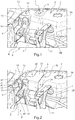
figure 2 est une vue une vue partielle en perspective de la partie avant gauche de l'habitacle d'un véhicule automobile dans laquelle est implantée un dispositif de maintien selon l'invention ; - la
figure 3 représente une vue de dessus de la zone de lafigure 2 ; - la
figure 4 est une vue en perspective partiellement arrachée de la zone d'implantation du dispositif de maintien selon l'invention ; - la
figure 5 représente une vue en perspective du dispositif de maintien selon l'invention ; et - la
figure 6 est une vue de dessous du dispositif de maintien selon l'invention. - Dans la suite et sur les
figures 2 à 4 , on a gardé les mêmes références pour les éléments identiques ou similaires à ceux présents sur lafigure 1 commentée dans la partie introductive de cette demande. - Tel qu'illustré sur ces figures, le dispositif de maintien 20 selon l'invention est destiné à être monté en remplacement d'un pion tel que 4 pour assurer le maintien de l'élément d'insonorisation 3 contre la traverse inférieure de baie 2.
- On va maintenant le décrire en détails en référence aux
figures 5 et 6 sur lesquelles il est monté seul. - Par convention, les termes « avant », « arrière », « externe », « longitudinal » et « transversal » sont définis par rapport à sa position de montage conventionnelle à l'intérieur d'un véhicule automobile.
- Le dispositif de maintien 20 est avantageusement venu de matière d'une seule pièce par moulage à partir d'un polymère thermoplastique tel que tel que le polypropylène, le polyamide ou l'ABS (Acrylonitrile Butadiène Styrène).
- Ce dispositif 20 comporte un corps principal 30 destiné à recouvrir partiellement la couverture d'insonorisation 3, ainsi qu'une extension 40 s'étendant dans le prolongement de ce corps 30 en arrière de ce dernier et depuis son extrémité latérale externe.
- Le corps principal 30 comprend une paroi de retenue inclinée 31 destinée à venir se plaquer, lors de la mise en place du dispositif 20 dans sa configuration de service illustrée par les
figures 2 à 4 , contre la face externe du panneau supérieur 3A de la couverture d'insonorisation 3 recouvrant la traverse inférieure de baie 2. - Ce corps principal 30 comporte également un fût de montage creux 32 saillant perpendiculairement depuis la face inférieure de la paroi de retenue 31 à proximité de son extrémité avant et prévu pour traverser un perçage de forme complémentaire 15 ménagé dans le panneau supérieur 3A de la couverture d'insonorisation 3 (
figure 4 ). - Comme illustré sur la
figure 5 , ce fût 32 est doté de pattes élastiques 33 saillant radialement et destinées à permettre son encliquetage sur un goujon 16 saillant à l'intérieur du perçage 15 depuis la face supérieure de la traverse inférieure de baie 2 (voirfigure 4 ). - Lorsque le dispositif 20 occupe sa configuration de service, la couverture d'insonorisation 3 se retrouve prise en sandwich entre la paroi de retenue 31 et la traverse inférieure de baie 2 de sorte à assurer son maintien.
- La paroi de retenue 31 est dimensionnée longitudinalement de sorte que, dans cette configuration de service, son bord arrière débouche à l'aplomb du panneau vertical 3B de la couverture d'insonorisation 3 recouvrant le tablier avant 1 (
figure 4 ). - Le corps principal 30 comprend en outre une façade arrière sensiblement plane 34 s'étendant verticalement depuis le bord arrière de la paroi de retenue 31 et agencée pour épouser la face externe du panneau vertical 3B, de sorte à empêcher tout pivotement du corps 30 (et donc du dispositif de maintien 20 dans son ensemble) selon au moins un premier sens de rotation autour de l'axe du goujon 5.
- L'extension 40, qui s'étend en biais vers l'arrière et du côté externe du corps principal 30, comporte un toit plan incliné 41 prolongeant la paroi de retenue 31 de ce corps ainsi que deux murets 42, 43 s'étendant verticalement depuis le bord arrière du toit 31 dans le prolongement l'une de l'autre.
- Plus précisément, le premier muret vertical 42 s'étend vers l'arrière de manière sensiblement perpendiculaire à la façade 34 du corps principal 30 en la prolongeant depuis son bord latéral externe, tandis que le second muret vertical 43 s'étend en biais vers l'arrière et du côté externe dans le prolongement du premier muret 42.
- Au niveau du coin inférieur arrière du second muret vertical 43, l'extension 40 présente en outre une découpe rectangulaire 44 (
figure 5 ). - Cette découpe 44 est conformée de sorte à s'emboîter par correspondance de forme sur un support latéral 9 lorsque le dispositif vient occuper sa configuration de service.
- La coopération entre cette découpe 44 et le support latéral 9 permet d'empêcher tout déplacement vertical du dispositif 20 ainsi que tout pivotement de ce dernier selon le second sens de rotation autour de l'axe du goujon 5.
- Le premier muret vertical 42 comprend en outre une interface d'accueil pour une agrafe d'attache 50 (ici de type à enrubanner) servant à assurer le maintien du faisceau électrique de pavillon 13 contre ce muret 42, tel qu'illustré sur les
figures 2 à 6 . - Cette interface d'accueil est en l'espèce constituée par un orifice oblong 45 ménagé dans ce muret 42 et destiné à permettre l'encliquetage de l'embase de type sapin 51 de l'agrafe 50 (
figure 6 ). - Le second muret vertical 43 comprend également une interface d'accueil pour une agrafe d'attache 60 (ici de type à enrubanner) servant à assurer le maintien du faisceau électrique d'habitacle 14 contre ce muret 43, tel qu'illustré sur les
figures 2 à 4 . - Cette interface d'accueil est en l'espèce constituée par un orifice circulaire 46 ménagé dans ce muret 43 et destiné à permettre l'encliquetage de l'embase de type sapin 61 de l'agrafe 60 (
figure 6 ). - Le fait de prévoir des orifices 45, 46 de formes différentes permet d'éviter tour risque d'erreur par l'opérateur sur la ligne de montage lors de la mise en place des agrafes 50, 60.
- Selon des variantes de réalisation non représentées de l'invention, le dispositif de maintien est conformé différemment.
- Les différentes parois constituant le corps principal et l'extension peuvent ainsi présenter des formes et des dimensions différentes.
- Ce dispositif de maintien peut également être dépourvu d'extension telle que 40. Dans un tel cas de figure, la ou les interfaces d'accueil pour les agrafes d'attache sont alors ménagées directement sur la façade arrière du corps principal.
Claims (10)
- Dispositif de maintien d'une couverture d'insonorisation (3) de traverse inférieure de baie (2) et de tablier avant (1) d'un véhicule automobile, comportant une paroi de retenue (31) et un organe de montage creux (32) s'étendant depuis ladite paroi de retenue (31), ledit dispositif étant apte à occuper une configuration de service dans laquelle ledit organe de montage (32) traverse un perçage (15) ménagé dans ladite couverture (3) en étant encliqueté sur un goujon (5) saillant à l'intérieur dudit perçage (15) depuis ladite traverse inférieure de baie (2) de sorte que ladite couverture d'insonorisation (3) soit prise en sandwich entre ladite paroi de retenue (31) et ladite traverse inférieure de baie (2) ;
caractérisé en ce qu'il comporte en outre au moins une paroi d'attache (42, 43) reliée rigidement à ladite paroi de retenue (31) et dotée d'au moins une interface d'accueil (45, 46) pour une agrafe de bridage (50, 60) d'un faisceau électrique (13, 14). - Dispositif de maintien selon la revendication 1, caractérisé en ce que chaque dite interface d'accueil comprend au moins un orifice (45, 46).
- Dispositif de maintien selon l'une des revendications 1 ou 2, caractérisé en ce qu'il comporte un corps principal (30) comprenant ladite paroi de retenue (31) et une façade (32) s'étendant verticalement depuis le bord arrière de ladite paroi de retenue (31), ladite façade (32) étant conformée de sorte à s'étendre parallèlement audit tablier avant (1) dans ladite configuration de service en épousant une portion de ladite couverture d'insonorisation (3).
- Dispositif de maintien selon la revendication 3, caractérisé en ce que ladite façade constitue une dite paroi d'attache.
- Dispositif de maintien selon l'une des revendications 3 ou 4, caractérisé en ce qu'il comporte une extension (40) comportant au moins un premier muret vertical (42) prolongeant ladite façade (32) du corps principal (30) vers l'arrière depuis l'un de ses bords latéraux.
- Dispositif de maintien selon la revendication 5, caractérisé en ce que ladite extension (40) comporte en outre un second muret vertical (43) s'étendant en biais vers l'arrière dans le prolongement dudit premier muret vertical (42).
- Dispositif de maintien selon l'une des revendications 5 ou 6, caractérisé en ce qu'au moins un dit muret vertical (42, 43) de ladite extension (40) constitue une dite paroi d'attache.
- Dispositif de maintien selon l'une des revendications 5 à 7, caractérisé en ce que ladite extension (40) présente une découpe (44) ménagée dans un dit muret (43) et conformée de sorte à, dans ladite configuration de service, s'emboîter par correspondance de forme sur un élément support (9) solidaire de la structure de caisse dudit véhicule.
- Dispositif de maintien selon l'une des revendications 1 à 8, caractérisé en ce qu'il est venu de moulage d'une seule pièce à partir d'un matériau thermoplastique.
- Ensemble comportant un dispositif de maintien conforme à l'une des revendications 1 à 9 ainsi qu'au moins une agrafe de bridage (50, 60) d'un faisceau électrique (13, 14) fixée sur une dite interface d'accueil (45, 46).
Applications Claiming Priority (2)
| Application Number | Priority Date | Filing Date | Title |
|---|---|---|---|
| FR1754553A FR3066749B1 (fr) | 2017-05-23 | 2017-05-23 | Dispositif de maintien d’une couverture d’insonorisation de traverse inferieure de baie et de tablier avant. |
| PCT/FR2018/050870 WO2018215706A1 (fr) | 2017-05-23 | 2018-04-06 | Dispositif de maintien d'une couverture d'insonorisation de traverse inferieure de baie et de tablier avant |
Publications (2)
| Publication Number | Publication Date |
|---|---|
| EP3630550A1 EP3630550A1 (fr) | 2020-04-08 |
| EP3630550B1 true EP3630550B1 (fr) | 2021-03-17 |
Family
ID=59297106
Family Applications (1)
| Application Number | Title | Priority Date | Filing Date |
|---|---|---|---|
| EP18723900.9A Active EP3630550B1 (fr) | 2017-05-23 | 2018-04-06 | Dispositif de maintien d'une couverture d'insonorisation de traverse inferieure de baie et de tablier avant |
Country Status (4)
| Country | Link |
|---|---|
| EP (1) | EP3630550B1 (fr) |
| ES (1) | ES2871377T3 (fr) |
| FR (1) | FR3066749B1 (fr) |
| WO (1) | WO2018215706A1 (fr) |
Families Citing this family (3)
| Publication number | Priority date | Publication date | Assignee | Title |
|---|---|---|---|---|
| FR3095490B1 (fr) * | 2019-04-29 | 2021-04-16 | Psa Automobiles Sa | Support de fixation multifonction pour la fixation d’éléments de raccordement sur un moteur thermique |
| FR3111306B1 (fr) * | 2020-06-16 | 2022-12-16 | Psa Automobiles Sa | Dispositif d’attache et de guidage pour câble ou tuyau cheminant sur le plancher d’un véhicule |
| FR3147998A1 (fr) * | 2023-04-21 | 2024-10-25 | Renault S.A.S | Support multifonction pour véhicule automobile |
Family Cites Families (4)
| Publication number | Priority date | Publication date | Assignee | Title |
|---|---|---|---|---|
| US5601899A (en) * | 1995-03-17 | 1997-02-11 | Cascade Engineering, Inc. | Sheet with integral fastener |
| FR2812064B1 (fr) * | 2000-07-19 | 2003-01-03 | Renault | Dispositif de fixation d'element de cablage ou analogue sur materiau mou, notamment insonorisant pour voiture |
| FR2899301B1 (fr) * | 2006-04-04 | 2008-05-16 | Renault Sas | Dispositif de solidarisation de cables electriques sur un support dans un vehicule automobile |
| FR3000622A1 (fr) * | 2013-01-02 | 2014-07-04 | Peugeot Citroen Automobiles Sa | Agrafe d'attache pour le montage d'un cable sur un support |
-
2017
- 2017-05-23 FR FR1754553A patent/FR3066749B1/fr not_active Expired - Fee Related
-
2018
- 2018-04-06 EP EP18723900.9A patent/EP3630550B1/fr active Active
- 2018-04-06 ES ES18723900T patent/ES2871377T3/es active Active
- 2018-04-06 WO PCT/FR2018/050870 patent/WO2018215706A1/fr not_active Ceased
Non-Patent Citations (1)
| Title |
|---|
| None * |
Also Published As
| Publication number | Publication date |
|---|---|
| FR3066749A1 (fr) | 2018-11-30 |
| FR3066749B1 (fr) | 2019-06-07 |
| BR112019024596A2 (pt) | 2020-06-09 |
| WO2018215706A1 (fr) | 2018-11-29 |
| EP3630550A1 (fr) | 2020-04-08 |
| ES2871377T3 (es) | 2021-10-28 |
Similar Documents
| Publication | Publication Date | Title |
|---|---|---|
| EP3630550B1 (fr) | Dispositif de maintien d'une couverture d'insonorisation de traverse inferieure de baie et de tablier avant | |
| EP2678194B1 (fr) | Support d'enrouleur de ceinture de securite | |
| EP3735363B1 (fr) | Dispositif d'attache et de guidage pour faisceaux éléctriques cheminant entre un longeron et sa garniture d'habillage | |
| EP3835136B1 (fr) | Ensemble pour la fixation d'une batterie a bord d'un véhicule comportant une bride de fixation avec une patte d'indexation et de détrompage | |
| EP1787869B1 (fr) | Véhicule comportant un dispositif de guidage et d'évacuation de l'eau | |
| EP3154826B1 (fr) | Agencement d'un élément de garniture de planche de bord d'un véhicule automobile sur un élément de support de cette planche de bord | |
| FR2868371A1 (fr) | Ensemble de montage d'une barre de toit longitudinale sur un toit d'un vehicule automobile | |
| EP1717106B1 (fr) | Agencement pour le support dans un véhicule automobile d'un boîtier électronique | |
| EP4103431B1 (fr) | Support pour au moins un haut-parleur latéral arrière de véhicule | |
| FR3111306A1 (fr) | Dispositif d’attache et de guidage pour câble ou tuyau cheminant sur le plancher d’un véhicule | |
| FR3041302A1 (fr) | Barre anti-rapprochement de vehicule automobile agencee pour la reception d’un faisceau de raccordement electrique. | |
| FR2886894A1 (fr) | Systeme de fixation d'une console centrale de vehicule | |
| EP0375509B1 (fr) | Dispositif de fixation de tubes rigides et de nappes souples sur un véhicule automobile | |
| EP2132062B1 (fr) | Assemblage de fixation d'un module de coussin de securite sur une structure mecaniquement resistante de la planche de bord | |
| FR3148329A1 (fr) | Dispositif de câblage pour un véhicule automobile | |
| FR3139109A1 (fr) | Dispositif d’appui pour pied de véhicule automobile et véhicule automobile équipé d’un tel dispositif | |
| FR3152456A1 (fr) | Dispositif de fixation d’un module de sécurité | |
| WO2024069065A1 (fr) | Caisse pour véhicule automobile comprenant un longeronnet avec une pièce de renfort | |
| FR3152768A1 (fr) | Dispositif d’emblème pour élément de carrosserie avant d’un véhicule automobile | |
| WO2016146922A1 (fr) | Structure de planche de bord d'un habitacle de vehicule automobile | |
| EP1645492B1 (fr) | Dispositif de fixation d'un protecteur de roue sur la structure d'un véhicule automobile, avec moyens de filtration des vibrations | |
| FR3124479A1 (fr) | Élément de garniture de seuil de porte d’un véhicule automobile permettant la fixation d’un tapis d’habitacle et structure de plancher de véhicule comportant un tél élément | |
| WO2021105577A1 (fr) | Déflecteur pour coussin gonflable de sécurité de type rideau | |
| FR2986758A1 (fr) | Support de fixation d'une barre de toit, ensemble de fixation et vehicule correspondants | |
| FR3094938A1 (fr) | Console de pavillon pour véhicule automobile |
Legal Events
| Date | Code | Title | Description |
|---|---|---|---|
| STAA | Information on the status of an ep patent application or granted ep patent |
Free format text: STATUS: UNKNOWN |
|
| STAA | Information on the status of an ep patent application or granted ep patent |
Free format text: STATUS: THE INTERNATIONAL PUBLICATION HAS BEEN MADE |
|
| PUAI | Public reference made under article 153(3) epc to a published international application that has entered the european phase |
Free format text: ORIGINAL CODE: 0009012 |
|
| STAA | Information on the status of an ep patent application or granted ep patent |
Free format text: STATUS: REQUEST FOR EXAMINATION WAS MADE |
|
| 17P | Request for examination filed |
Effective date: 20191115 |
|
| AK | Designated contracting states |
Kind code of ref document: A1 Designated state(s): AL AT BE BG CH CY CZ DE DK EE ES FI FR GB GR HR HU IE IS IT LI LT LU LV MC MK MT NL NO PL PT RO RS SE SI SK SM TR |
|
| AX | Request for extension of the european patent |
Extension state: BA ME |
|
| DAX | Request for extension of the european patent (deleted) | ||
| RAV | Requested validation state of the european patent: fee paid |
Extension state: MA Effective date: 20191115 |
|
| GRAP | Despatch of communication of intention to grant a patent |
Free format text: ORIGINAL CODE: EPIDOSNIGR1 |
|
| STAA | Information on the status of an ep patent application or granted ep patent |
Free format text: STATUS: GRANT OF PATENT IS INTENDED |
|
| INTG | Intention to grant announced |
Effective date: 20201012 |
|
| RAP1 | Party data changed (applicant data changed or rights of an application transferred) |
Owner name: PSA AUTOMOBILES SA |
|
| GRAS | Grant fee paid |
Free format text: ORIGINAL CODE: EPIDOSNIGR3 |
|
| GRAA | (expected) grant |
Free format text: ORIGINAL CODE: 0009210 |
|
| STAA | Information on the status of an ep patent application or granted ep patent |
Free format text: STATUS: THE PATENT HAS BEEN GRANTED |
|
| AK | Designated contracting states |
Kind code of ref document: B1 Designated state(s): AL AT BE BG CH CY CZ DE DK EE ES FI FR GB GR HR HU IE IS IT LI LT LU LV MC MK MT NL NO PL PT RO RS SE SI SK SM TR |
|
| REG | Reference to a national code |
Ref country code: GB Ref legal event code: FG4D Free format text: NOT ENGLISH |
|
| REG | Reference to a national code |
Ref country code: CH Ref legal event code: EP |
|
| REG | Reference to a national code |
Ref country code: DE Ref legal event code: R096 Ref document number: 602018014091 Country of ref document: DE |
|
| REG | Reference to a national code |
Ref country code: IE Ref legal event code: FG4D Free format text: LANGUAGE OF EP DOCUMENT: FRENCH |
|
| REG | Reference to a national code |
Ref country code: AT Ref legal event code: REF Ref document number: 1371947 Country of ref document: AT Kind code of ref document: T Effective date: 20210415 |
|
| REG | Reference to a national code |
Ref country code: DE Ref legal event code: R084 Ref document number: 602018014091 Country of ref document: DE |
|
| REG | Reference to a national code |
Ref country code: SK Ref legal event code: T3 Ref document number: E 36878 Country of ref document: SK |
|
| REG | Reference to a national code |
Ref country code: LT Ref legal event code: MG9D |
|
| REG | Reference to a national code |
Ref country code: GB Ref legal event code: 746 Effective date: 20210705 |
|
| PG25 | Lapsed in a contracting state [announced via postgrant information from national office to epo] |
Ref country code: BG Free format text: LAPSE BECAUSE OF FAILURE TO SUBMIT A TRANSLATION OF THE DESCRIPTION OR TO PAY THE FEE WITHIN THE PRESCRIBED TIME-LIMIT Effective date: 20210617 Ref country code: FI Free format text: LAPSE BECAUSE OF FAILURE TO SUBMIT A TRANSLATION OF THE DESCRIPTION OR TO PAY THE FEE WITHIN THE PRESCRIBED TIME-LIMIT Effective date: 20210317 Ref country code: GR Free format text: LAPSE BECAUSE OF FAILURE TO SUBMIT A TRANSLATION OF THE DESCRIPTION OR TO PAY THE FEE WITHIN THE PRESCRIBED TIME-LIMIT Effective date: 20210618 Ref country code: HR Free format text: LAPSE BECAUSE OF FAILURE TO SUBMIT A TRANSLATION OF THE DESCRIPTION OR TO PAY THE FEE WITHIN THE PRESCRIBED TIME-LIMIT Effective date: 20210317 Ref country code: NO Free format text: LAPSE BECAUSE OF FAILURE TO SUBMIT A TRANSLATION OF THE DESCRIPTION OR TO PAY THE FEE WITHIN THE PRESCRIBED TIME-LIMIT Effective date: 20210617 |
|
| REG | Reference to a national code |
Ref country code: AT Ref legal event code: MK05 Ref document number: 1371947 Country of ref document: AT Kind code of ref document: T Effective date: 20210317 |
|
| REG | Reference to a national code |
Ref country code: NL Ref legal event code: MP Effective date: 20210317 |
|
| PG25 | Lapsed in a contracting state [announced via postgrant information from national office to epo] |
Ref country code: SE Free format text: LAPSE BECAUSE OF FAILURE TO SUBMIT A TRANSLATION OF THE DESCRIPTION OR TO PAY THE FEE WITHIN THE PRESCRIBED TIME-LIMIT Effective date: 20210317 Ref country code: LV Free format text: LAPSE BECAUSE OF FAILURE TO SUBMIT A TRANSLATION OF THE DESCRIPTION OR TO PAY THE FEE WITHIN THE PRESCRIBED TIME-LIMIT Effective date: 20210317 Ref country code: RS Free format text: LAPSE BECAUSE OF FAILURE TO SUBMIT A TRANSLATION OF THE DESCRIPTION OR TO PAY THE FEE WITHIN THE PRESCRIBED TIME-LIMIT Effective date: 20210317 |
|
| REG | Reference to a national code |
Ref country code: ES Ref legal event code: GC2A Effective date: 20210825 |
|
| PG25 | Lapsed in a contracting state [announced via postgrant information from national office to epo] |
Ref country code: NL Free format text: LAPSE BECAUSE OF FAILURE TO SUBMIT A TRANSLATION OF THE DESCRIPTION OR TO PAY THE FEE WITHIN THE PRESCRIBED TIME-LIMIT Effective date: 20210317 |
|
| REG | Reference to a national code |
Ref country code: ES Ref legal event code: FG2A Ref document number: 2871377 Country of ref document: ES Kind code of ref document: T3 Effective date: 20211028 |
|
| PG25 | Lapsed in a contracting state [announced via postgrant information from national office to epo] |
Ref country code: LT Free format text: LAPSE BECAUSE OF FAILURE TO SUBMIT A TRANSLATION OF THE DESCRIPTION OR TO PAY THE FEE WITHIN THE PRESCRIBED TIME-LIMIT Effective date: 20210317 Ref country code: EE Free format text: LAPSE BECAUSE OF FAILURE TO SUBMIT A TRANSLATION OF THE DESCRIPTION OR TO PAY THE FEE WITHIN THE PRESCRIBED TIME-LIMIT Effective date: 20210317 Ref country code: CZ Free format text: LAPSE BECAUSE OF FAILURE TO SUBMIT A TRANSLATION OF THE DESCRIPTION OR TO PAY THE FEE WITHIN THE PRESCRIBED TIME-LIMIT Effective date: 20210317 Ref country code: AT Free format text: LAPSE BECAUSE OF FAILURE TO SUBMIT A TRANSLATION OF THE DESCRIPTION OR TO PAY THE FEE WITHIN THE PRESCRIBED TIME-LIMIT Effective date: 20210317 Ref country code: SM Free format text: LAPSE BECAUSE OF FAILURE TO SUBMIT A TRANSLATION OF THE DESCRIPTION OR TO PAY THE FEE WITHIN THE PRESCRIBED TIME-LIMIT Effective date: 20210317 |
|
| PG25 | Lapsed in a contracting state [announced via postgrant information from national office to epo] |
Ref country code: IS Free format text: LAPSE BECAUSE OF FAILURE TO SUBMIT A TRANSLATION OF THE DESCRIPTION OR TO PAY THE FEE WITHIN THE PRESCRIBED TIME-LIMIT Effective date: 20210717 Ref country code: PL Free format text: LAPSE BECAUSE OF FAILURE TO SUBMIT A TRANSLATION OF THE DESCRIPTION OR TO PAY THE FEE WITHIN THE PRESCRIBED TIME-LIMIT Effective date: 20210317 Ref country code: PT Free format text: LAPSE BECAUSE OF FAILURE TO SUBMIT A TRANSLATION OF THE DESCRIPTION OR TO PAY THE FEE WITHIN THE PRESCRIBED TIME-LIMIT Effective date: 20210719 Ref country code: RO Free format text: LAPSE BECAUSE OF FAILURE TO SUBMIT A TRANSLATION OF THE DESCRIPTION OR TO PAY THE FEE WITHIN THE PRESCRIBED TIME-LIMIT Effective date: 20210317 |
|
| REG | Reference to a national code |
Ref country code: DE Ref legal event code: R097 Ref document number: 602018014091 Country of ref document: DE |
|
| PG25 | Lapsed in a contracting state [announced via postgrant information from national office to epo] |
Ref country code: LU Free format text: LAPSE BECAUSE OF NON-PAYMENT OF DUE FEES Effective date: 20210406 |
|
| REG | Reference to a national code |
Ref country code: BE Ref legal event code: MM Effective date: 20210430 |
|
| PLBE | No opposition filed within time limit |
Free format text: ORIGINAL CODE: 0009261 |
|
| STAA | Information on the status of an ep patent application or granted ep patent |
Free format text: STATUS: NO OPPOSITION FILED WITHIN TIME LIMIT |
|
| PG25 | Lapsed in a contracting state [announced via postgrant information from national office to epo] |
Ref country code: DK Free format text: LAPSE BECAUSE OF FAILURE TO SUBMIT A TRANSLATION OF THE DESCRIPTION OR TO PAY THE FEE WITHIN THE PRESCRIBED TIME-LIMIT Effective date: 20210317 Ref country code: CH Free format text: LAPSE BECAUSE OF NON-PAYMENT OF DUE FEES Effective date: 20210430 Ref country code: AL Free format text: LAPSE BECAUSE OF FAILURE TO SUBMIT A TRANSLATION OF THE DESCRIPTION OR TO PAY THE FEE WITHIN THE PRESCRIBED TIME-LIMIT Effective date: 20210317 Ref country code: MC Free format text: LAPSE BECAUSE OF FAILURE TO SUBMIT A TRANSLATION OF THE DESCRIPTION OR TO PAY THE FEE WITHIN THE PRESCRIBED TIME-LIMIT Effective date: 20210317 Ref country code: LI Free format text: LAPSE BECAUSE OF NON-PAYMENT OF DUE FEES Effective date: 20210430 |
|
| 26N | No opposition filed |
Effective date: 20211220 |
|
| PG25 | Lapsed in a contracting state [announced via postgrant information from national office to epo] |
Ref country code: SI Free format text: LAPSE BECAUSE OF FAILURE TO SUBMIT A TRANSLATION OF THE DESCRIPTION OR TO PAY THE FEE WITHIN THE PRESCRIBED TIME-LIMIT Effective date: 20210317 |
|
| PG25 | Lapsed in a contracting state [announced via postgrant information from national office to epo] |
Ref country code: IT Free format text: LAPSE BECAUSE OF FAILURE TO SUBMIT A TRANSLATION OF THE DESCRIPTION OR TO PAY THE FEE WITHIN THE PRESCRIBED TIME-LIMIT Effective date: 20210317 Ref country code: IE Free format text: LAPSE BECAUSE OF NON-PAYMENT OF DUE FEES Effective date: 20210406 |
|
| PG25 | Lapsed in a contracting state [announced via postgrant information from national office to epo] |
Ref country code: IS Free format text: LAPSE BECAUSE OF FAILURE TO SUBMIT A TRANSLATION OF THE DESCRIPTION OR TO PAY THE FEE WITHIN THE PRESCRIBED TIME-LIMIT Effective date: 20210717 |
|
| PG25 | Lapsed in a contracting state [announced via postgrant information from national office to epo] |
Ref country code: BE Free format text: LAPSE BECAUSE OF NON-PAYMENT OF DUE FEES Effective date: 20210430 |
|
| PG25 | Lapsed in a contracting state [announced via postgrant information from national office to epo] |
Ref country code: CY Free format text: LAPSE BECAUSE OF FAILURE TO SUBMIT A TRANSLATION OF THE DESCRIPTION OR TO PAY THE FEE WITHIN THE PRESCRIBED TIME-LIMIT Effective date: 20210317 |
|
| PG25 | Lapsed in a contracting state [announced via postgrant information from national office to epo] |
Ref country code: HU Free format text: LAPSE BECAUSE OF FAILURE TO SUBMIT A TRANSLATION OF THE DESCRIPTION OR TO PAY THE FEE WITHIN THE PRESCRIBED TIME-LIMIT; INVALID AB INITIO Effective date: 20180406 |
|
| REG | Reference to a national code |
Ref country code: DE Ref legal event code: R081 Ref document number: 602018014091 Country of ref document: DE Owner name: STELLANTIS AUTO SAS, FR Free format text: FORMER OWNER: PSA AUTOMOBILES SA, POISSY, FR |
|
| PG25 | Lapsed in a contracting state [announced via postgrant information from national office to epo] |
Ref country code: MK Free format text: LAPSE BECAUSE OF FAILURE TO SUBMIT A TRANSLATION OF THE DESCRIPTION OR TO PAY THE FEE WITHIN THE PRESCRIBED TIME-LIMIT Effective date: 20210317 |
|
| VS25 | Lapsed in a validation state [announced via postgrant information from nat. office to epo] |
Ref country code: MA Free format text: LAPSE BECAUSE OF FAILURE TO SUBMIT A TRANSLATION OF THE DESCRIPTION OR TO PAY THE FEE WITHIN THE PRESCRIBED TIME-LIMIT Effective date: 20210317 |
|
| PG25 | Lapsed in a contracting state [announced via postgrant information from national office to epo] |
Ref country code: MT Free format text: LAPSE BECAUSE OF FAILURE TO SUBMIT A TRANSLATION OF THE DESCRIPTION OR TO PAY THE FEE WITHIN THE PRESCRIBED TIME-LIMIT Effective date: 20210317 |
|
| PGFP | Annual fee paid to national office [announced via postgrant information from national office to epo] |
Ref country code: DE Payment date: 20250319 Year of fee payment: 8 |
|
| PGFP | Annual fee paid to national office [announced via postgrant information from national office to epo] |
Ref country code: ES Payment date: 20250502 Year of fee payment: 8 |
|
| PG25 | Lapsed in a contracting state [announced via postgrant information from national office to epo] |
Ref country code: TR Free format text: LAPSE BECAUSE OF FAILURE TO SUBMIT A TRANSLATION OF THE DESCRIPTION OR TO PAY THE FEE WITHIN THE PRESCRIBED TIME-LIMIT Effective date: 20210317 |
|
| PGFP | Annual fee paid to national office [announced via postgrant information from national office to epo] |
Ref country code: GB Payment date: 20260319 Year of fee payment: 9 |
|
| PGFP | Annual fee paid to national office [announced via postgrant information from national office to epo] |
Ref country code: FR Payment date: 20260320 Year of fee payment: 9 |
|
| PGFP | Annual fee paid to national office [announced via postgrant information from national office to epo] |
Ref country code: SK Payment date: 20260325 Year of fee payment: 9 |