EP3630368B1 - Aerosol device and method for providing an aerosol - Google Patents
Aerosol device and method for providing an aerosol Download PDFInfo
- Publication number
- EP3630368B1 EP3630368B1 EP18726134.2A EP18726134A EP3630368B1 EP 3630368 B1 EP3630368 B1 EP 3630368B1 EP 18726134 A EP18726134 A EP 18726134A EP 3630368 B1 EP3630368 B1 EP 3630368B1
- Authority
- EP
- European Patent Office
- Prior art keywords
- aerosol
- interior space
- housing
- flow
- liquid
- Prior art date
- Legal status (The legal status is an assumption and is not a legal conclusion. Google has not performed a legal analysis and makes no representation as to the accuracy of the status listed.)
- Active
Links
- 239000000443 aerosol Substances 0.000 title claims description 369
- 238000000034 method Methods 0.000 title claims description 14
- 239000007788 liquid Substances 0.000 claims description 98
- 238000009826 distribution Methods 0.000 claims description 32
- 239000000654 additive Substances 0.000 claims description 27
- 230000000996 additive effect Effects 0.000 claims description 27
- 230000005484 gravity Effects 0.000 claims description 12
- 238000000926 separation method Methods 0.000 claims description 9
- 239000007921 spray Substances 0.000 claims description 6
- 238000000605 extraction Methods 0.000 claims description 5
- 230000006735 deficit Effects 0.000 claims description 3
- 239000012530 fluid Substances 0.000 claims description 2
- 238000005507 spraying Methods 0.000 claims description 2
- 239000000126 substance Substances 0.000 claims description 2
- 239000007789 gas Substances 0.000 description 37
- 238000005192 partition Methods 0.000 description 21
- 238000005461 lubrication Methods 0.000 description 6
- 239000000203 mixture Substances 0.000 description 6
- 239000000314 lubricant Substances 0.000 description 5
- CURLTUGMZLYLDI-UHFFFAOYSA-N Carbon dioxide Chemical compound O=C=O CURLTUGMZLYLDI-UHFFFAOYSA-N 0.000 description 4
- 238000007599 discharging Methods 0.000 description 4
- 230000002349 favourable effect Effects 0.000 description 4
- 238000007373 indentation Methods 0.000 description 4
- 230000001105 regulatory effect Effects 0.000 description 4
- IJGRMHOSHXDMSA-UHFFFAOYSA-N Atomic nitrogen Chemical compound N#N IJGRMHOSHXDMSA-UHFFFAOYSA-N 0.000 description 3
- 230000001050 lubricating effect Effects 0.000 description 3
- 229910002092 carbon dioxide Inorganic materials 0.000 description 2
- 239000001569 carbon dioxide Substances 0.000 description 2
- 230000000694 effects Effects 0.000 description 2
- 239000007787 solid Substances 0.000 description 2
- FGRBYDKOBBBPOI-UHFFFAOYSA-N 10,10-dioxo-2-[4-(N-phenylanilino)phenyl]thioxanthen-9-one Chemical compound O=C1c2ccccc2S(=O)(=O)c2ccc(cc12)-c1ccc(cc1)N(c1ccccc1)c1ccccc1 FGRBYDKOBBBPOI-UHFFFAOYSA-N 0.000 description 1
- 241000237942 Conidae Species 0.000 description 1
- 239000003570 air Substances 0.000 description 1
- 230000015572 biosynthetic process Effects 0.000 description 1
- 229910052757 nitrogen Inorganic materials 0.000 description 1
- JCXJVPUVTGWSNB-UHFFFAOYSA-N nitrogen dioxide Inorganic materials O=[N]=O JCXJVPUVTGWSNB-UHFFFAOYSA-N 0.000 description 1
- 239000002245 particle Substances 0.000 description 1
- 238000007493 shaping process Methods 0.000 description 1
- 239000013589 supplement Substances 0.000 description 1
- 239000000725 suspension Substances 0.000 description 1
- 230000007704 transition Effects 0.000 description 1
Images


Classifications
-
- B—PERFORMING OPERATIONS; TRANSPORTING
- B05—SPRAYING OR ATOMISING IN GENERAL; APPLYING FLUENT MATERIALS TO SURFACES, IN GENERAL
- B05B—SPRAYING APPARATUS; ATOMISING APPARATUS; NOZZLES
- B05B7/00—Spraying apparatus for discharge of liquids or other fluent materials from two or more sources, e.g. of liquid and air, of powder and gas
- B05B7/0012—Apparatus for achieving spraying before discharge from the apparatus
-
- B—PERFORMING OPERATIONS; TRANSPORTING
- B05—SPRAYING OR ATOMISING IN GENERAL; APPLYING FLUENT MATERIALS TO SURFACES, IN GENERAL
- B05B—SPRAYING APPARATUS; ATOMISING APPARATUS; NOZZLES
- B05B14/00—Arrangements for collecting, re-using or eliminating excess spraying material
-
- B—PERFORMING OPERATIONS; TRANSPORTING
- B05—SPRAYING OR ATOMISING IN GENERAL; APPLYING FLUENT MATERIALS TO SURFACES, IN GENERAL
- B05B—SPRAYING APPARATUS; ATOMISING APPARATUS; NOZZLES
- B05B7/00—Spraying apparatus for discharge of liquids or other fluent materials from two or more sources, e.g. of liquid and air, of powder and gas
- B05B7/02—Spray pistols; Apparatus for discharge
- B05B7/04—Spray pistols; Apparatus for discharge with arrangements for mixing liquids or other fluent materials before discharge
- B05B7/0416—Spray pistols; Apparatus for discharge with arrangements for mixing liquids or other fluent materials before discharge with arrangements for mixing one gas and one liquid
-
- B—PERFORMING OPERATIONS; TRANSPORTING
- B23—MACHINE TOOLS; METAL-WORKING NOT OTHERWISE PROVIDED FOR
- B23Q—DETAILS, COMPONENTS, OR ACCESSORIES FOR MACHINE TOOLS, e.g. ARRANGEMENTS FOR COPYING OR CONTROLLING; MACHINE TOOLS IN GENERAL CHARACTERISED BY THE CONSTRUCTION OF PARTICULAR DETAILS OR COMPONENTS; COMBINATIONS OR ASSOCIATIONS OF METAL-WORKING MACHINES, NOT DIRECTED TO A PARTICULAR RESULT
- B23Q11/00—Accessories fitted to machine tools for keeping tools or parts of the machine in good working condition or for cooling work; Safety devices specially combined with or arranged in, or specially adapted for use in connection with, machine tools
- B23Q11/10—Arrangements for cooling or lubricating tools or work
- B23Q11/1038—Arrangements for cooling or lubricating tools or work using cutting liquids with special characteristics, e.g. flow rate, quality
- B23Q11/1046—Arrangements for cooling or lubricating tools or work using cutting liquids with special characteristics, e.g. flow rate, quality using a minimal quantity of lubricant
-
- Y—GENERAL TAGGING OF NEW TECHNOLOGICAL DEVELOPMENTS; GENERAL TAGGING OF CROSS-SECTIONAL TECHNOLOGIES SPANNING OVER SEVERAL SECTIONS OF THE IPC; TECHNICAL SUBJECTS COVERED BY FORMER USPC CROSS-REFERENCE ART COLLECTIONS [XRACs] AND DIGESTS
- Y02—TECHNOLOGIES OR APPLICATIONS FOR MITIGATION OR ADAPTATION AGAINST CLIMATE CHANGE
- Y02P—CLIMATE CHANGE MITIGATION TECHNOLOGIES IN THE PRODUCTION OR PROCESSING OF GOODS
- Y02P70/00—Climate change mitigation technologies in the production process for final industrial or consumer products
- Y02P70/10—Greenhouse gas [GHG] capture, material saving, heat recovery or other energy efficient measures, e.g. motor control, characterised by manufacturing processes, e.g. for rolling metal or metal working
Definitions
- the present invention relates to an aerosol device and a method for providing an aerosol.
- Aerosol devices and methods for providing aerosols are used, for example, in the field of tool lubrication.
- use in lubricating systems for example so-called minimum quantity lubricating systems, can be provided.
- the object of the present invention is to provide an aerosol device which makes it possible to provide an aerosol with an optimized composition, in particular an optimized droplet size distribution (liquid droplet size distribution, particle size distribution).
- the aerosol device includes an aerosol housing.
- the aerosol device comprises one or more aerosol nozzles for generating an aerosol flow from a transport gas and a liquid, the one or more aerosol nozzles being directed into an interior space of the aerosol housing and/or being arranged in the aerosol housing.
- the aerosol device comprises one or more transport channel connections for connecting one or more transport channels, by means of which the aerosol can be discharged from the interior of the aerosol housing.
- the aerosol device comprises a separating device for separating liquid droplets from the aerosol, with the separating device being arranged between the one or more aerosol nozzles on the one hand and the one or more transport channels on the other hand with respect to a flow direction of the aerosol.
- a transport channel is in particular a line.
- a transport channel is a flexible tube.
- the aerosol can be transported in particular to a delivery location by means of the transport channel.
- the transport channels can be dimensioned identically.
- the separating device preferably comprises a centrifugal separator and/or a deflection separator.
- the separating device is in particular size-selective, for example in such a way that, based on a droplet size distribution of the liquid in the aerosol, larger liquid droplets are separated and comparatively smaller liquid droplets are transported further in the transport gas.
- Liquid droplets are preferably separated on an outer wall of the aerosol housing.
- the interior of the aerosol housing is at least approximately rotationally symmetrical.
- one or more aerosol nozzles are directed at least approximately tangentially into the interior space, so that in particular an annular or spiral or helically rotating aerosol gas flow can be generated in the interior space of the aerosol housing.
- Separation on the outer wall of the aerosol housing preferably results from the fact that due to the centrifugal force that occurs, heavier liquid droplets are transported radially outwards and finally adhere to the outer wall.
- the interior of the aerosol housing includes an annular flow area and a central area.
- the annular flow area is in particular that area in which the annular or spiral or helical rotating aerosol gas flow is formed.
- the ring flow area essentially surrounds the central area in a ring shape.
- the one or more aerosol nozzles are directed into the annular flow area.
- the one or more transport channel connections are directly adjacent to the central area.
- Aerosol can thus be removed directly from the interior of the aerosol housing from the central area.
- the annular flow area and the central area are spatially separated from one another by means of a partition.
- the partition is essentially in the form of a hollow cylinder, for example in the form of a hollow circular cylinder.
- the partition is preferably attached to the aerosol housing.
- the partition wall is fixed to a top wall of the aerosol housing and extends downwards in the direction of gravity, starting from the top wall.
- a connection between the top wall and the partition wall in the area of the top wall is preferably impermeable to fluids.
- the dividing wall preferably protrudes freely into the interior of the aerosol housing, so that the dividing wall can be flowed around, in particular at a lower end of the dividing wall with respect to the direction of gravity.
- the partition wall preferably surrounds the central area and is surrounded by the annular flow area.
- partition wall, an outer wall of the aerosol housing, a delivery device to be described later and/or an aerosol chamber floor to be described later are arranged and/or formed concentrically and/or coaxially with respect to a longitudinal center plane of the housing.
- One or more transport channel connections are preferably arranged and/or formed in the top wall of the aerosol housing.
- One or more transport channel connections are arranged and/or formed in particular on an upper end section of the central area.
- one or more outlet nozzles which in particular are part of the one or more transport channel connections, protrude into the interior, preferably protrude into the central area of the interior.
- One or more outlet openings are preferably arranged and/or formed in the top wall of the aerosol housing.
- One or more outlet openings are arranged and/or formed in particular on an upper end section of the central area.
- the outlet openings preferably each comprise a funnel-shaped inflow area or are each formed at least in sections as a funnel-shaped inflow area.
- the outlet openings are formed by a separate component which is connected, for example, to the aerosol housing, in particular the top wall, and/or is fixed to the aerosol housing, in particular the top wall.
- the separate component is in particular designed in one piece.
- the separate component is in particular a removal element.
- the removal element is an essentially cylindrical element which has in particular one, two, three, four or more than four outlet openings.
- the extraction element preferably has an inflow side facing the interior of the aerosol housing when the extraction element is in the installed state.
- the inflow side can be provided, for example, with an indentation, in particular an indentation in the shape of a segment of a sphere or a segment of a sphere.
- One or more removal areas, in particular funnel-shaped removal areas, of the outlet openings are preferably arranged in this indentation.
- One or more transport channel connections and/or fastening points for fastening the removal element are preferably arranged and/or formed on a side opposite the indentation and/or on a side of the removal element facing away from the interior and/or the top wall.
- the removal element can be fixed to the ceiling wall in particular by means of a screw connection.
- the removal element preferably comprises a receiving area for receiving and/or fixing and/or arranging the partition.
- the aerosol device includes a delivery device for delivering an additive, in particular a liquid, to the interior of the aerosol housing.
- the delivery device is in particular a different device from the one or more aerosol nozzles.
- the delivery device comprises or is formed from an additional aerosol nozzle and/or a spray nozzle for spraying in a liquid and/or a drop generator for introducing drops of liquid.
- an additive in particular a liquid, can be supplied to the aerosol outside the annular flow area and/or downstream of the separating device with respect to a flow direction of the aerosol.
- the delivery device is arranged in the direction of gravity directly below the central area of the interior space of the aerosol housing and/or directed into the central area.
- liquid droplets can be fed to the aerosol by means of the feed device, with the liquid droplets being larger than the liquid droplets still remaining in the aerosol downstream of the separating device, for example by a factor of at least approximately 5, in particular at least approximately 10, for example at least approximately 50.
- the aerosol housing preferably comprises an aerosol area, in which the aerosol is guided, and a collection area, in which liquid separated from the aerosol is collected.
- the collection area is arranged directly below the aerosol area.
- An aerosol compartment floor preferably separates the aerosol area from the collection area.
- An opening in particular an annular opening, is preferably provided in an edge area of the aerosol base adjacent to the outer wall, so that liquid separated in the aerosol area can flow off into the collection area.
- the floor of the aerosol chamber is, for example, arranged and/or designed in the shape of a cone or a cone shell.
- the aerosol chamber floor is preferably designed in such a way that it generates and/or intensifies a cyclone effect within the aerosol housing.
- the delivery device is arranged in the aerosol chamber floor.
- the aerosol device comprises a plurality of transport channel connections and/or transport channels which have different diameters from one another, so that in particular different aerosol variants can optionally be used different droplet size distributions of the aerosol can in particular be discharged and/or transported with as little impairment as possible.
- the phrase "as free as possible of impairments" means in particular that the droplet size distribution of the aerosol at an initial region of the transport channels facing the aerosol housing corresponds at least approximately to a droplet size distribution of the aerosol at an end of the transport channels facing away from the aerosol housing. "At least approximately” denotes a deviation of at most approximately 20%, for example at most approximately 10%, of the values that are decisive for the droplet size distribution.
- the aerosol device comprises a control device, by means of which a droplet size distribution and/or a volume flow of the aerosol generated and/or provided can be adjusted in a targeted manner.
- control device can be used in particular to influence the one or more aerosol nozzles and/or the supply device for supplying the additive, in particular the liquid.
- an aerosol can be generated in a targeted manner by means of the one or more aerosol nozzles and optimized in terms of the droplet size distribution by the targeted supply of the additive by means of the supply device.
- control device can preferably also ensure that the aerosol generated in the aerosol housing reaches the delivery location with a composition that is as unchanged as possible.
- One or more transport channels, the aerosol housing, in particular an outer wall and/or the partition wall and/or the aerosol chamber floor, and/or the feed device and/or the one or more aerosol nozzles can preferably be temperature-controlled, for example can be cooled or heated.
- either the transport gas and/or the liquid and/or the additive and/or the aerosol can preferably optionally be temperature-controlled, in particular cooled or heated.
- the liquid used to generate the aerosol by means of one or more aerosol nozzles can be provided as an additive that can be supplied by means of the supply device.
- Such a liquid is in particular a lubricant, for example oil.
- the additive comprises or is formed from a gas, in particular air, nitrogen, carbon dioxide (CO 2 ).
- the additive is liquid or solid, for example the additive can thereby be used to cool the aerosol.
- the additive is, for example, liquid nitrogen or carbon dioxide (CO 2 ) in the solid state (so-called CO 2 snow).
- a pressure in the interior of the aerosol housing can preferably be set, controlled and/or regulated by means of the control device.
- the pressure can be varied to adapt, set and/or control the aerosol quantity, the droplet size distribution, the aerosol mass flow and/or the aerosol volume flow.
- the pressure in the interior of the aerosol housing is, for example, at least approximately 10 bar, in particular at least approximately 15 bar, preferably at least approximately 20 bar, in particular before and/or during the generation of aerosol and/or before and/or during the provision of aerosol.
- the pressure in the interior of the aerosol housing is preferably at most approximately 35 bar, in particular at most approximately 30 bar at most about 25 bar.
- the aerosol device can be operated in a pressure range between approximately 10 bar and approximately 25 bar.
- transport gas for example atomizing air
- the aerosol which can be generated in particular by means of the aerosol nozzles and is available after flowing through the separating device, preferably has a droplet size distribution in which the most frequently occurring droplet size is preferably less than 10 ⁇ m, in particular less than 5 ⁇ m, for example less than 1 ⁇ m.
- Liquid droplets preferably have a droplet size distribution in which the most frequently occurring droplet size is greater than 20 ⁇ m, in particular greater than 50 ⁇ m, preferably greater than 100 ⁇ m.
- liquid droplets supplied by means of the feed device preferably form wall liquid, in particular wall oil, which is guided, in particular flows, along the walls in the transport channels.
- the droplets in the aerosol are preferably transported with the transport gas and do not come into contact with a wall of the transport channel.
- the aerosol device according to the invention is particularly suitable for use in a minimum quantity lubrication system.
- Such a minimum quantity lubrication system can be used in particular in a machine tool.
- the present invention therefore also relates to a minimum quantity lubrication system and a machine tool which includes such a minimum quantity lubrication system.
- the present invention also relates to a method for providing an aerosol.
- the object of the invention is to provide an aerosol with an optimized composition.
- this object is achieved by a method according to the independent method claim.
- the interior of the aerosol housing comprises an annular flow area and a central area, with the annular flow area and the central area being spatially separated from one another by means of a partition and with the annular flow area surrounding the central area in the form of a ring, with the aerosol in the annular flow area of the interior initially being used to separate Liquid droplets are guided in a ring flow or spiral flow or helical flow, then into the within the Ring flow or spiral flow or helical flow arranged central region of the interior is deflected and finally fed to the one or more transport channel connections.
- the deflection takes place in particular at a lower end of the partition with respect to the direction of gravity.
- the additive is supplied to the aerosol in such a way that a median of the droplet size distribution of the additive is at least one order of magnitude greater than the median of the droplet size distribution of the aerosol.
- the aerosol discharged from the interior of the aerosol housing preferably includes liquid droplets generated by the one or more aerosol nozzles on the one hand and liquid droplets generated by the feed device on the other hand.
- An average diameter of the liquid droplets is preferably at least approximately 10 times, in particular at least approximately 50 times, an average diameter of the liquid droplets.
- the liquid droplets are preferably introduced into the interior in such a way that they are guided to the one or more transport channel connections and finally to the transport channels together with the aerosol or only by means of transport gas.
- the aerosol is preferably provided at a delivery location.
- the provision location is preferably arranged at a common end of a number of transport channels.
- different numbers of transport channels and/or differently dimensioned transport channels are preferably used to provide the aerosol at the delivery location.
- the transport channels preferably all connect at the same time or at least several at the same time the interior of the aerosol housing with the deployment location. In order to select one or more transport channels for providing an aerosol with a desired droplet size distribution, it is therefore preferably not necessary to exchange a transport channel or to supplement or remove a transport channel. It can preferably be switched easily, for example by means of a valve device, between individual transport channels and/or a plurality of transport channels and optionally between individual transport channels.
- one or more transport channels are used to provide the lubricant at the point of delivery. If a significantly smaller quantity of lubricant is now required for a short time, one can preferably switch to one or more other transport channels, in particular to prevent further transport of the liquid droplets and/or liquid droplets still being transported in the one or more transport channels.
- an undesired subsequent conveyance of large drops of liquid, in particular wall oil, to the delivery location can be avoided by switching to another transport channel or several other transport channels.
- the aerosol device according to the invention is in particular a so-called 1-channel system in which transport gas on the one hand and liquid, in particular in the form of liquid droplets, on the other hand, are conveyed together starting from the aerosol device and are therefore not materially separated.
- the aerosol device is particularly suitable for use in cutting machine tools.
- an aerosol is preferably to be understood as meaning a substance mixture which comprises a gas, in particular transport gas, and liquid droplets, in particular oil droplets.
- a suspension time of the liquid droplets is preferably at least approximately 5 seconds, for example at least approximately 10 seconds, preferably at least approximately 15 seconds.
- a conveying speed of the aerosol in the transport channels is preferably at most approximately 50 m/s, in particular at most approximately 40 m/s, preferably at most approximately 30 m/s.
- liquid which, for example, was introduced exclusively via the supply device into the interior of the aerosol housing.
- the one or more aerosol nozzles on the one hand and the delivery device on the other hand can be switched on and off separately from one another.
- the one or more aerosol nozzles on the one hand and the delivery device on the other hand can be switched on or off either individually or together.
- Several aerosol nozzles are preferably controlled by means of several valves.
- valves are preferably provided, which control different numbers of aerosol nozzles.
- All aerosol nozzles are preferably optimized for minimum transport gas consumption and for optimizing the aerosol composition, in particular the droplet size distribution, in particular in order to generate maximum aerosol density.
- the aerosol device can optionally generate different aerosol volume flows and/or aerosol mass flows for one or more delivery locations by selectively switching on or off one or more aerosol nozzles, in particular without impairing the aerosol quality, in particular a droplet size distribution.
- the aerosol device preferably comprises a separating device, which in particular comprises one or more flow-through bodies.
- a flow-through body is in particular an object through which aerosol flows during operation of the aerosol device.
- a flow-through body can be a perforated plate element, for example.
- cascaded perforated plate elements are provided, through which the aerosol can flow, in particular one after the other.
- a flow deflection can be achieved by means of one or more flow-through bodies.
- a perforated plate element can, for example, be designed essentially in the shape of a truncated cone or in the shape of a cone.
- a perforated plate element is preferably a perforated plate.
- a flow-through body forms or includes a brush separator.
- a brush separator comprises in particular a multiplicity of bristles and/or projections, for example rod-shaped projections, around which aerosol flows during operation of the aerosol device, in particular for influencing a (liquid) droplet size distribution.
- One or more flow-through bodies are arranged in particular in a spatial area surrounded by the partition wall, in particular in a central area.
- the partition wall preferably surrounds the one or more flow-through bodies in a substantially ring-shaped and/or cylinder-jacket-shaped manner.
- the illustrated embodiment of an aerosol device denoted as a whole by 100 is, for example, part of a minimum quantity lubrication system for lubricating tools.
- the aerosol device 100 can be provided, for example, as part of a machine tool.
- the aerosol device 100 comprises an aerosol housing 102 in which an aerosol to be provided is generated.
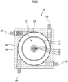
- the aerosol device 100 also includes a plurality of aerosol nozzles 104 which are directed into an interior space 106 of the aerosol housing 102 .
- the aerosol nozzles 104 are arranged in particular in an upper region of the aerosol housing 102 with respect to the direction of gravity.
- the aerosol nozzles 104 are arranged essentially tangentially to an outer wall 108 of the aerosol housing 102 .
- the aerosol nozzles 104 thus enable, in particular, the formation of an annular flow within the interior space 106 of the aerosol housing 102.
- the interior 106 of the aerosol housing 102 is divided into several areas.
- the interior space 106 includes an annular flow area 110 into which the aerosol nozzles 104 open.
- the annular flow area 110 surrounds a central area 112 of the interior space 106.
- annular flow area 110 and the central area 112 are separated from one another by means of a partition wall 114 .
- the separating wall 114 is in particular a separating cylinder 116.
- the partition wall 114 is arranged in particular on a top wall 118 of the aerosol housing 102 and extends downwards in the direction of gravity, starting from the top wall 118 .
- the interior 106 of the aerosol housing 102 also includes a collection area 120 in which liquid separated from the aerosol, in particular oil, can collect.
- the annular flow area 110 and the central area 112 are part of an aerosol space or aerosol area 122 of the interior space 106.
- the aerosol area 122 and the collection area 120 are separated from one another in particular by means of an aerosol chamber floor 124 .
- the aerosol chamber floor 124 is in particular a horizontal partition which delimits the collection area 120 at the top.
- the aerosol chamber floor 124 is particularly permeable, so that liquid separated in the aerosol area 122 can reach the collecting area 120 downwards.
- an annular gap is formed between the outer wall 108 of the aerosol housing 102 and the aerosol chamber floor 124 .
- the annular gap is in particular a drainage gap 126.
- the collection area 120 forms, in particular, a liquid reservoir 128. Liquid is supplied from the liquid reservoir 128 to the aerosol nozzles 104, in particular via one or more liquid lines 130.
- the aerosol device 100 preferably comprises a transport gas source 132, by means of which a transport gas, in particular compressed air, is provided.
- a transport gas in particular compressed air
- One or more valve devices 134 are used to supply the transport gas to the aerosol nozzles 104.
- valve devices 134 are, in particular, aerosol valves 136.
- connection between the aerosol valves 136 and the aerosol nozzles 104 is formed in particular by gas lines 138 .
- an additional gas duct 140 of the aerosol device 100 can be provided.
- the additional gas duct 140 makes it possible, in particular, to supply additional transport gas from the transport gas source 132 into the central region 112 of the interior space 106.
- a proportional valve 142 can be provided in a gas line 138 of the additional gas guide 140 in order to vary a volume flow of the transport gas supplied via the additional gas guide 140 .
- one or more manometers 144 are also used to monitor and/or control the aerosol device 100.
- the aerosol device 100 preferably comprises a control device 146, by means of which in particular the entire aerosol device 100 can be controlled and/or regulated.
- the aerosol device 100 also preferably includes a delivery device 148 for delivering an additive to the aerosol generated in the aerosol housing 102 .
- the delivery device 148 is arranged in particular in the aerosol chamber floor 124 and/or directed into the central region 112 of the interior 106 .
- the delivery device 148 preferably comprises an aerosol nozzle 150 and/or a spray nozzle 152.
- a finely nebulized liquid in particular can be metered into the central area 112 and the aerosol arranged therein.
- a liquid in droplet form with droplet sizes that are large compared to the aerosol can be introduced into the central region 112 and the aerosol and/or transport gas guided therein.
- valve device 134 embodied as a wall oil valve 154
- the quantity of the additive supplied via the feed device 148 can preferably be controlled and/or regulated.
- a droplet size of an aerosol or spray supplied via the supply device 148 can preferably be adjusted in this way.
- the aerosol device 100 further comprises one or more transport channel connectors 156 for connecting one or more transport channels 158.
- the aerosol generated in the interior 106 of the aerosol housing 102 can be discharged via these transport channel connections 156 and the transport channels 158 and supplied to a (not shown) supply location.
- the transport channel connections 156 and/or the transport channels 158 can have one or more outlet nozzles 159 which in particular protrude into the interior space 106 of the aerosol housing 102 .
- aerosol can be taken up and discharged directly in the central area 112 .
- the illustrated embodiment of the aerosol device 100 works as follows: An aerosol is generated from a transport gas and a liquid, in particular oil, by means of the aerosol nozzles 104 and introduced into the annular flow region 110 of the interior 106 of the aerosol housing 102 .
- the tangential arrangement and/or orientation of the aerosol nozzles 104 preferably results in a ring-shaped or helical or spiral-shaped aerosol flow in the annular flow area 110 .
- the aerosol flows in particular around the partition wall 114 and downwards in the direction of gravity.
- the separated liquid then flows along the outer wall 108 and through the drainage gap 126 into the collection area 120.
- An additive is supplied to the aerosol via the supply device 148 .
- This additive is in particular the same liquid as was already used to generate the aerosol in the aerosol nozzles 104 .
- the feed device 148 preferably produces droplets with a comparatively large diameter.
- the droplets generated by means of the feed device 148 are larger than the liquid droplets deposited on the outer wall 108 of the aerosol initially generated by means of the aerosol nozzles 104 .
- the aerosol device 100 thus comprises a separating device 160, which is designed in particular as a centrifugal separator 162 and/or deflection separator 164 in order to initially separate liquid droplets that are in an undesirable size range and are generated by the aerosol nozzles 104.
- a separating device 160 which is designed in particular as a centrifugal separator 162 and/or deflection separator 164 in order to initially separate liquid droplets that are in an undesirable size range and are generated by the aerosol nozzles 104.
- drops of liquid are then fed in, which are preferably larger, in particular by at least one Order of magnitude greater than the liquid droplets separated by means of the separating device 160 .
- the combination of aerosol nozzles 104 and feed device 148 can thus produce a very specific droplet size distribution in the central area 112 .
- the aerosol nozzles 104 and the delivery device 148 can optionally be switched on and/or switched off alternatively or together in order ultimately to be able to optionally generate different droplet size distributions in the central area 112 .
- the aerosol arranged in the central area 112 can be guided via the transport channel connections 156 and the transport channels 158 to one or more delivery locations.
- this transport of the aerosol to the place of delivery can be adapted to the droplet size distribution in order ultimately to also ensure a desired aerosol composition at the place of delivery.
- one in the Figures 6 to 8 illustrated alternative embodiment of an aerosol device 100 differs from that in FIGS Figures 1 to 5 illustrated embodiment essentially in that the separating device 160 alternatively or in addition to the features of the separating device 160 described so far according to the in the Figures 1 to 5 illustrated embodiment comprises one or more flow-through bodies 166.
- the flow-through bodies 166 are arranged in particular in the interior 106 of the aerosol housing 102 and are preferably surrounded by the partition 114, in particular the separating cylinder 116.
- the flow-through bodies 166 are preferably arranged one behind the other with respect to a flow direction of the aerosol in the interior space 106, so that the flow-through bodies 166 are flowed through successively with the aerosol.
- Each flow-through body 166 is designed, for example, as a perforated plate element 168, in particular as a perforated plate 170.
- Each flow-through body 166 is preferably designed essentially in the shape of the jacket of a cone and/or the jacket of a truncated cone, with a tip (cone tip) preferably pointing downwards in the direction of gravity.
- the flow-through bodies 166 are preferably fixed in the interior 106 and/or fixed relative to one another by means of one or more support elements 172 .
- the flow-through bodies 166 preferably have a large number of through-openings through which the aerosol flows, as a result of which separation of liquid can ultimately be achieved.
- a suitable selection of the hole diameter preferably results in a desired influencing and/or selection of the (liquid) droplet size distribution.
- the aerosol chamber floor 124 is essentially in the form of a truncated cone or the shape of a truncated cone, with a cone tip 174 of the aerosol chamber floor 124 preferably pointing downwards in the direction of gravity.
- a cyclone effect within the interior 106 of the aerosol housing 102 can preferably be generated and/or intensified by means of the aerosol chamber floor 124 .
- a drainage gap 126 or a drainage opening is then preferably arranged on a radially inner area of the aerosol chamber floor 124 facing the cone tip 174 .
- a top wall 118 of the aerosol housing 102 is preferably flow-optimized by one or more additional components or by suitable shaping.
- the aerosol device 100 preferably comprises a removal element 176, by means of which the aerosol can be discharged from the interior 106 of the aerosol housing 102, in particular while largely avoiding air turbulence and/or flow deflections.
- the removal element 176 which is separately in the Figures 7 and 8 is shown, for this purpose is in particular a substantially cylindrical component, which comprises a receiving area 178 for receiving the partition wall 114 and/or can be fixed to the top wall 118 of the aerosol housing 102 by means of one or more fastening points 180.
- the removal element 176 includes, in particular, several, for example four, funnel-shaped inflow areas 182, which are part of outlet openings 184 for discharging the aerosol from the interior 106.
- the outlet openings 184 in particular border on transport channel connections 156 and/or transport channels 158 .
- Each transport channel 158 and/or each transport channel connection 156 is preferably assigned an outlet opening 184 with a separate inflow area 182 .
- the extraction element 176 has in particular rounded inflow areas 182, in particular without edges, corners or other flow-influencing sections.
- the aerosol can thus be fed from the interior 106 to the transport channels 158 particularly efficiently and with little turbulence by means of the inflow regions 182 of the extraction element 176 .
- the inflow regions 182 can open into a depression in the removal element 176 in the form of a segment of a sphere on their side facing the interior space 106 .
- one inside 9 illustrated further alternative embodiment of an aerosol device 100 differs from that in FIGS Figures 6 to 8
- the brush separator 186 comprises in particular a multiplicity of rod-shaped projections which are connected to one another in particular centrally.
- the rod-shaped projections in particular bristles, are preferably aligned at an angle to the direction of gravity. As a result, it is preferably possible for separated liquid to flow off easily. In particular, the liquid flows together centrally in the radial direction and along the support element 172 for mounting the brush separator 186 downwards in the direction of the aerosol chamber floor 124 and finally into the collection area 120.
- the brush separator 186 from the embodiment according to FIG 9 at the in the Figures 1 to 5 illustrated embodiment may be provided.
Description
Die vorliegende Erfindung betrifft eine Aerosolvorrichtung und ein Verfahren zum Bereitstellen eines Aerosols. Aerosolvorrichtungen und Verfahren zum Bereitstellen von Aerosolen kommen beispielsweise auf dem Gebiet der Werkzeugschmierung zum Einsatz. Insbesondere kann eine Verwendung in Schmiersystemen, beispielsweise sogenannten Minimalmengenschmiersystemen, vorgesehen sein.The present invention relates to an aerosol device and a method for providing an aerosol. Aerosol devices and methods for providing aerosols are used, for example, in the field of tool lubrication. In particular, use in lubricating systems, for example so-called minimum quantity lubricating systems, can be provided.
Aerosolvorrichtungen und Verfahren zum Bereitstellen von Aerosolen sind beispielsweise aus folgenden Druckschriften bekannt:
-
DE 103 49 642 A1 DE 101 04 012 C2 DE 101 01 889 A1 DE 102 17 927 B4 -
DE 20 2015 102 484 U1 DE 20 2009 017 542 U1 DE 10 2009 060 454 A1 EP 2 839 882 A1 EP 2 574 424 B1 EP 2 574 423 A1 DE 20 2013 103 529 U1 EP 2 338 587 A1 -
WO 03/002263 A1 US 5,800,598 A EP 0 608 176 A1 US 2005/017092 A1 -
US 2009/230215 A1 US 6,290,024 B1 DE 27 55 060 A1 US 3,515,676 A -
EP 0 941 769 A1
-
DE 103 49 642 A1 DE 101 04 012 C2 DE 101 01 889 A1 DE 102 17 927 B4 -
DE 20 2015 102 484 U1 DE 20 2009 017 542 U1 DE 10 2009 060 454 A1 EP 2 839 882 A1 EP 2 574 424 B1 EP 2 574 423 A1 DE 20 2013 103 529 U1 EP 2 338 587 A1 -
WO 03/002263 A1 US 5,800,598A EP 0 608 176 A1 U.S. 2005/017092 A1 -
U.S. 2009/230215 A1 US 6,290,024 B1 DE 27 55 060 A1 US 3,515,676A -
EP 0 941 769 A1
Der vorliegenden Erfindung liegt die Aufgabe zugrunde, eine Aerosolvorrichtung bereitzustellen, welche die Bereitstellung eines Aerosols mit optimierter Zusammensetzung, insbesondere optimierter Tröpfchengrößenverteilung (Liquidtröpfchengrößenverteilung, Teilchengrößenverteilung), ermöglicht.The object of the present invention is to provide an aerosol device which makes it possible to provide an aerosol with an optimized composition, in particular an optimized droplet size distribution (liquid droplet size distribution, particle size distribution).
Diese Aufgabe wird erfindungsgemäß durch eine Aerosolvorrichtung gemäß dem unabhängigen Vorrichtungsanspruch gelöst.According to the invention, this object is achieved by an aerosol device according to the independent device claim.
Die Aerosolvorrichtung umfasst ein Aerosolgehäuse.The aerosol device includes an aerosol housing.
Ferner umfasst die Aerosolvorrichtung eine oder mehrere Aerosoldüsen zur Erzeugung eines Aerosolstroms aus einem Transportgas und einem Liquid, wobei die eine oder die mehreren Aerosoldüsen in einen Innenraum des Aerosolgehäuses hineingerichtet und/oder in dem Aerosolgehäuse angeordnet sind.Furthermore, the aerosol device comprises one or more aerosol nozzles for generating an aerosol flow from a transport gas and a liquid, the one or more aerosol nozzles being directed into an interior space of the aerosol housing and/or being arranged in the aerosol housing.
Die Aerosolvorrichtung umfasst einen oder mehrere Transportkanalanschlüsse zum Anschließen eines oder mehrerer Transportkanäle, mittels welcher das Aerosol aus dem Innenraum des Aerosolgehäuses abführbar ist.The aerosol device comprises one or more transport channel connections for connecting one or more transport channels, by means of which the aerosol can be discharged from the interior of the aerosol housing.
Erfindungsgemäß ist vorgesehen, dass die Aerosolvorrichtung eine Abscheidevorrichtung zum Abscheiden von Liquidtröpfchen aus dem Aerosol umfasst, wobei die Abscheidevorrichtung bezüglich einer Strömungsrichtung des Aerosols zwischen der einen oder den mehreren Aerosoldüsen einerseits und dem einen oder den mehreren Transportkanälen andererseits angeordnet ist.According to the invention, it is provided that the aerosol device comprises a separating device for separating liquid droplets from the aerosol, with the separating device being arranged between the one or more aerosol nozzles on the one hand and the one or more transport channels on the other hand with respect to a flow direction of the aerosol.
Ein Transportkanal ist insbesondere eine Leitung. Beispielsweise ist ein Transportkanal ein flexibler Schlauch.A transport channel is in particular a line. For example, a transport channel is a flexible tube.
Mittels des Transportkanals ist das Aerosol insbesondere zu einem Bereitstellungsort transportierbar.The aerosol can be transported in particular to a delivery location by means of the transport channel.
Günstig kann es sein, wenn mehrere Transportkanäle vorgesehen sind, welche einerseits an dem Aerosolgehäuse festgelegt sind und andererseits an einem gemeinsamen Bereitstellungsort enden.It can be advantageous if several transport channels are provided, which on the one hand are fixed to the aerosol housing and on the other hand end at a common supply location.
Die Transportkanäle können dabei identisch dimensioniert sein.The transport channels can be dimensioned identically.
Vorzugsweise sind jedoch mehrere Transportkanäle mit unterschiedlichen Dimensionen vorgesehen. Hierdurch kann insbesondere eine optimierte Förderung des Aerosols bei unterschiedlichen Tröpfchengrößenverteilungen, Volumenströmen und/oder Massenströmen realisiert werden.However, several transport channels with different dimensions are preferably provided. In this way, in particular, an optimized delivery of the aerosol can be realized with different droplet size distributions, volume flows and/or mass flows.
Die Abscheidevorrichtung umfasst vorzugsweise einen Zentrifugenabscheider und/oder einen Umlenkabscheider.The separating device preferably comprises a centrifugal separator and/or a deflection separator.
Die Abscheidevorrichtung ist insbesondere größenselektiv, beispielsweise derart, dass bezogen auf eine Tröpfchengrößenverteilung des Liquids im Aerosol größere Liquidtröpfchen abgeschieden werden und vergleichsweise kleinere Liquidtröpfchen im Transportgas weitertransportiert werden.The separating device is in particular size-selective, for example in such a way that, based on a droplet size distribution of the liquid in the aerosol, larger liquid droplets are separated and comparatively smaller liquid droplets are transported further in the transport gas.
Die Abscheidung von Liquidtröpfchen erfolgt vorzugsweise an einer Außenwandung des Aerosolgehäuses.Liquid droplets are preferably separated on an outer wall of the aerosol housing.
Günstig kann es sein, wenn der Innenraum des Aerosolgehäuses zumindest näherungsweise rotationssymmetrisch ausgebildet ist.It can be favorable if the interior of the aerosol housing is at least approximately rotationally symmetrical.
Alternativ oder ergänzend hierzu kann vorgesehen sein, dass eine oder mehrere Aerosoldüsen zumindest näherungsweise tangential in den Innenraum hineingerichtet sind, so dass insbesondere ein ringförmig oder spiralförmig oder helikal rotierender Aerosolgasstrom im Innenraum des Aerosolgehäuses erzeugbar ist.Alternatively or in addition to this, it can be provided that one or more aerosol nozzles are directed at least approximately tangentially into the interior space, so that in particular an annular or spiral or helically rotating aerosol gas flow can be generated in the interior space of the aerosol housing.
Eine Abscheidung an der Außenwandung des Aerosolgehäuses ergibt sich vorzugsweise dadurch, dass aufgrund der auftretenden Zentrifugalkraft schwerere Liquidtröpfchen radial nach außen befördert werden und schließlich an der Außenwandung anhaften.Separation on the outer wall of the aerosol housing preferably results from the fact that due to the centrifugal force that occurs, heavier liquid droplets are transported radially outwards and finally adhere to the outer wall.
Der Innenraum des Aerosolgehäuses umfasst einen Ringstrombereich und einen Zentralbereich.The interior of the aerosol housing includes an annular flow area and a central area.
Der Ringstrombereich ist insbesondere derjenige Bereich, in welchem sich der ringförmig oder spiralförmig oder helikal rotierende Aerosolgasstrom ausbildet.The annular flow area is in particular that area in which the annular or spiral or helical rotating aerosol gas flow is formed.
Der Ringstrombereich umgibt den Zentralbereich im Wesentlichen ringförmig.The ring flow area essentially surrounds the central area in a ring shape.
Die eine oder die mehreren Aerosoldüsen sind in den Ringstrombereich hineingerichtet. Der eine oder die mehreren Transportkanalanschlüsse grenzen unmittelbar an den Zentralbereich an.The one or more aerosol nozzles are directed into the annular flow area. The one or more transport channel connections are directly adjacent to the central area.
Somit ist direkt aus dem Zentralbereich Aerosol aus dem Innenraum des Aerosolgehäuses entnehmbar.Aerosol can thus be removed directly from the interior of the aerosol housing from the central area.
Der Ringstrombereich und der Zentralbereich sind mittels einer Trennwandung räumlich voneinander getrennt.The annular flow area and the central area are spatially separated from one another by means of a partition.
Insbesondere ist die Trennwandung im Wesentlichen hohlzylinderförmig, beispielsweise hohlkreiszylinderförmig, ausgebildet.In particular, the partition is essentially in the form of a hollow cylinder, for example in the form of a hollow circular cylinder.
Die Trennwandung ist vorzugsweise an dem Aerosolgehäuse festgelegt.The partition is preferably attached to the aerosol housing.
Insbesondere ist die Trennwandung an einer Deckenwandung des Aerosolgehäuses festgelegt und erstreckt sich ausgehend von der Deckenwandung in der Schwerkraftrichtung nach unten.In particular, the partition wall is fixed to a top wall of the aerosol housing and extends downwards in the direction of gravity, starting from the top wall.
Eine Verbindung zwischen der Deckenwandung und der Trennwandung im Bereich der Deckenwandung ist vorzugsweise fluidundurchlässig.A connection between the top wall and the partition wall in the area of the top wall is preferably impermeable to fluids.
Vorzugsweise ragt die Trennwandung frei in den Innenraum des Aerosolgehäuses hinein, so dass die Trennwandung insbesondere an einem bezüglich der Schwerkraftrichtung unteren Ende der Trennwandung umströmbar ist.The dividing wall preferably protrudes freely into the interior of the aerosol housing, so that the dividing wall can be flowed around, in particular at a lower end of the dividing wall with respect to the direction of gravity.
Die Trennwandung umgibt vorzugsweise den Zentralbereich und ist von dem Ringstrombereich umgeben.The partition wall preferably surrounds the central area and is surrounded by the annular flow area.
Günstig kann es sein, wenn die Trennwandung, eine Außenwandung des Aerosolgehäuses, eine noch zu beschreibende Zuführvorrichtung und/oder ein noch zu beschreibender Aerosolraumboden konzentrisch und/oder koaxial bezüglich einer Gehäuselängsmittelebene angeordnet und/oder ausgebildet sind.It can be advantageous if the partition wall, an outer wall of the aerosol housing, a delivery device to be described later and/or an aerosol chamber floor to be described later are arranged and/or formed concentrically and/or coaxially with respect to a longitudinal center plane of the housing.
Ein oder mehrere Transportkanalanschlüsse sind vorzugsweise in der Deckenwandung des Aerosolgehäuses angeordnet und/oder ausgebildet.One or more transport channel connections are preferably arranged and/or formed in the top wall of the aerosol housing.
Ein oder mehrere Transportkanalanschlüsse sind insbesondere an einem oberen Endabschnitt des Zentralbereichs angeordnet und/oder ausgebildet.One or more transport channel connections are arranged and/or formed in particular on an upper end section of the central area.
Es kann vorgesehen sein, dass ein oder mehrere Auslassstutzen, welche insbesondere Bestandteil des einen oder der mehreren Transportkanalanschlüsse sind, in den Innenraum hineinragen, vorzugsweise in den Zentralbereich des Innenraums hineinragen.It can be provided that one or more outlet nozzles, which in particular are part of the one or more transport channel connections, protrude into the interior, preferably protrude into the central area of the interior.
Ein oder mehrere Auslassöffnungen sind vorzugsweise in der Deckenwandung des Aerosolgehäuses angeordnet und/oder ausgebildet.One or more outlet openings are preferably arranged and/or formed in the top wall of the aerosol housing.
Ein oder mehrere Auslassöffnungen sind insbesondere an einem oberen Endabschnitt des Zentralbereichs angeordnet und/oder ausgebildet.One or more outlet openings are arranged and/or formed in particular on an upper end section of the central area.
Es kann vorgesehen sein, dass ein oder mehrere Auslassöffnungen, an welche sich insbesondere ein oder mehrere Transportkanalanschlüsse und/oder ein oder mehrere Transportkanäle anschließen, bündig und/oder kantenfrei und/oder mit einem fließenden Übergang an eine Deckenwandung des Aerosolgehäuses angrenzen und/oder in die Deckenwandung des Aerosolgehäuses integriert sind und/oder an die Trennwandung des Aerosolgehäuses angrenzen und/oder in die Trennwandung des Aerosolgehäuses integriert sind.Provision can be made for one or more outlet openings, to which in particular one or more transport channel connections and/or one or more transport channels are connected, to border flush and/or without edges and/or with a smooth transition to a top wall of the aerosol housing and/or in are integrated into the top wall of the aerosol housing and/or adjoin the dividing wall of the aerosol housing and/or are integrated into the dividing wall of the aerosol housing.
Die Auslassöffnungen umfassen vorzugsweise jeweils einen trichterförmigen Einströmbereich oder sind jeweils zumindest abschnittsweise als ein trichterförmiger Einströmbereich ausgebildet.The outlet openings preferably each comprise a funnel-shaped inflow area or are each formed at least in sections as a funnel-shaped inflow area.
Insbesondere sind die Auslassöffnungen durch ein separates Bauteil gebildet, welches beispielsweise mit dem Aerosolgehäuse, insbesondere der Deckenwandung, verbunden und/oder an dem Aerosolgehäuse, insbesondere der Deckenwandung, festgelegt ist.In particular, the outlet openings are formed by a separate component which is connected, for example, to the aerosol housing, in particular the top wall, and/or is fixed to the aerosol housing, in particular the top wall.
Das separate Bauteil ist insbesondere einstückig ausgebildet.The separate component is in particular designed in one piece.
Das separate Bauteil ist insbesondere ein Entnahmeelement.The separate component is in particular a removal element.
Günstig kann es sein, wenn das Entnahmeelement ein im Wesentlichen zylindrisches Element ist, welches insbesondere eine, zwei, drei, vier oder mehr als vier Auslassöffnungen aufweist.It can be favorable if the removal element is an essentially cylindrical element which has in particular one, two, three, four or more than four outlet openings.
Das Entnahmeelement weist vorzugsweise eine im montierten Zustand des Entnahmeelements dem Innenraum des Aerosolgehäuses zugewandte Einströmseite auf.The extraction element preferably has an inflow side facing the interior of the aerosol housing when the extraction element is in the installed state.
Die Einströmseite kann beispielsweise mit einer Einbuchtung, insbesondere einer kugelsegment- oder kugelabschnittsförmigen Einbuchtung, versehen sein.The inflow side can be provided, for example, with an indentation, in particular an indentation in the shape of a segment of a sphere or a segment of a sphere.
In dieser Einbuchtung sind vorzugsweise ein oder mehrere Entnahmebereiche, insbesondere trichterförmige Entnahmebereiche, der Auslassöffnungen angeordnet.One or more removal areas, in particular funnel-shaped removal areas, of the outlet openings are preferably arranged in this indentation.
An einer der Einbuchtung gegenüberliegenden Seite und/oder an einer dem Innenraum abgewandten Seite und/oder der Deckenwandung zugewandten Seite des Entnahmeelements sind vorzugsweise ein oder mehrere Transportkanalanschlüsse und/oder Befestigungsstellen zur Befestigung des Entnahmeelements angeordnet und/oder ausgebildet.One or more transport channel connections and/or fastening points for fastening the removal element are preferably arranged and/or formed on a side opposite the indentation and/or on a side of the removal element facing away from the interior and/or the top wall.
Das Entnahmeelement kann insbesondere mittels einer Schraubverbindung an der Deckenwandung festgelegt werden.The removal element can be fixed to the ceiling wall in particular by means of a screw connection.
Vorzugsweise umfasst das Entnahmeelement einen Aufnahmebereich zur Aufnahme und/oder Festlegung und/oder Anordnung der Trennwandung.The removal element preferably comprises a receiving area for receiving and/or fixing and/or arranging the partition.
Die Aerosolvorrichtung umfasst eine Zuführvorrichtung zum Zuführen eines Zusatzstoffs, insbesondere eines Liquids, zu dem Innenraum des Aerosolgehäuses.The aerosol device includes a delivery device for delivering an additive, in particular a liquid, to the interior of the aerosol housing.
Die Zuführvorrichtung ist insbesondere eine von der einen oder den mehreren Aerosoldüsen verschiedene Vorrichtung.The delivery device is in particular a different device from the one or more aerosol nozzles.
Beispielsweise kann vorgesehen sein, dass die Zuführvorrichtung eine zusätzliche Aerosoldüse und/oder eine Sprühdüse zum Einsprühen eines Liquids und/oder einen Tropfenerzeuger zum Einleiten von Liquidtropfen umfasst oder hieraus gebildet ist.For example, it can be provided that the delivery device comprises or is formed from an additional aerosol nozzle and/or a spray nozzle for spraying in a liquid and/or a drop generator for introducing drops of liquid.
Mittels der Zuführvorrichtung ist ein Zusatzstoff, insbesondere ein Liquid außerhalb des Ringstrombereichs und/oder bezüglich einer Strömungsrichtung des Aerosols stromabwärts der Abscheidevorrichtung zu dem Aerosol zuführbar.By means of the supply device, an additive, in particular a liquid, can be supplied to the aerosol outside the annular flow area and/or downstream of the separating device with respect to a flow direction of the aerosol.
Die Zuführvorrichtung ist in Schwerkraftrichtung direkt unter dem Zentralbereich des Innenraums des Aerosolgehäuses angeordnet und/oder in den Zentralbereich hineingerichtet.The delivery device is arranged in the direction of gravity directly below the central area of the interior space of the aerosol housing and/or directed into the central area.
Mittels der Zuführvorrichtung sind insbesondere Liquidtropfen zu dem Aerosol zuführbar, wobei die Liquidtropfen im Vergleich zu den stromabwärts der Abscheidevorrichtung noch im Aerosol verbliebenen Liquidtröpfchen größer dimensioniert sind, beispielsweise um einen Faktor von mindestens ungefähr 5, insbesondere mindestens ungefähr 10, beispielsweise mindestens ungefähr 50.In particular, liquid droplets can be fed to the aerosol by means of the feed device, with the liquid droplets being larger than the liquid droplets still remaining in the aerosol downstream of the separating device, for example by a factor of at least approximately 5, in particular at least approximately 10, for example at least approximately 50.
Das Aerosolgehäuse umfasst vorzugsweise einen Aerosolbereich, in welchem das Aerosol geführt wird, und einen Sammelbereich, in welchem aus dem Aerosol abgeschiedenes Liquid gesammelt wird. Insbesondere ist der Sammelbereich direkt unter dem Aerosolbereich angeordnet.The aerosol housing preferably comprises an aerosol area, in which the aerosol is guided, and a collection area, in which liquid separated from the aerosol is collected. In particular, the collection area is arranged directly below the aerosol area.
Ein Aerosolraumboden trennt vorzugsweise den Aerosolbereich von dem Sammelbereich.An aerosol compartment floor preferably separates the aerosol area from the collection area.
In einem an die Außenwandung angrenzenden Randbereich des Aerosolbodens ist vorzugsweise eine Öffnung, insbesondere eine ringförmige Öffnung, vorgesehen, so dass im Aerosolbereich abgeschiedenes Liquid in den Sammelbereich abfließen kann.An opening, in particular an annular opening, is preferably provided in an edge area of the aerosol base adjacent to the outer wall, so that liquid separated in the aerosol area can flow off into the collection area.
Der Aerosolraumboden ist beispielsweise kegelförmig oder kegelmantelförmig angeordnet und/oder ausgebildet.The floor of the aerosol chamber is, for example, arranged and/or designed in the shape of a cone or a cone shell.
Der Aerosolraumboden ist vorzugsweise so gestaltet, dass dieser eine Zyklonwirkung innerhalb des Aerosolgehäuses erzeugt und/oder verstärkt.The aerosol chamber floor is preferably designed in such a way that it generates and/or intensifies a cyclone effect within the aerosol housing.
Vorteilhaft kann es sein, wenn die Zuführvorrichtung in dem Aerosolraumboden angeordnet ist.It can be advantageous if the delivery device is arranged in the aerosol chamber floor.
Günstig kann es sein, wenn die Aerosolvorrichtung mehrere Transportkanalanschlüsse und/oder Transportkanäle umfasst, welche voneinander verschiedene Durchmesser aufweisen, so dass insbesondere wahlweise verschiedene Aerosolvarianten mit unterschiedlichen Tröpfchengrößenverteilungen des Aerosols insbesondere möglichst beeinträchtigungsfrei abführbar und/oder transportierbar sind.It can be advantageous if the aerosol device comprises a plurality of transport channel connections and/or transport channels which have different diameters from one another, so that in particular different aerosol variants can optionally be used different droplet size distributions of the aerosol can in particular be discharged and/or transported with as little impairment as possible.
Unter der Formulierung "möglichst beeinträchtigungsfrei" ist insbesondere zu verstehen, dass die Tröpfchengrößenverteilung des Aerosols an einem dem Aerosolgehäuse zugewandten Anfangsbereich der Transportkanäle zumindest näherungsweise einer Tröpfchengrößenverteilung des Aerosols an einem dem Aerosolgehäuse abgewandten Ende der Transportkanäle entspricht. "Zumindest näherungsweise" bezeichnet dabei eine Abweichung von höchstens ungefähr 20 %, beispielsweise höchstens ungefähr 10 %, der für die Tröpfchengrößenverteilung maßgeblichen Werte.The phrase "as free as possible of impairments" means in particular that the droplet size distribution of the aerosol at an initial region of the transport channels facing the aerosol housing corresponds at least approximately to a droplet size distribution of the aerosol at an end of the transport channels facing away from the aerosol housing. "At least approximately" denotes a deviation of at most approximately 20%, for example at most approximately 10%, of the values that are decisive for the droplet size distribution.
Günstig kann es sein, wenn die Aerosolvorrichtung eine Steuervorrichtung umfasst, mittels welcher eine Tröpfchengrößenverteilung und/oder ein Volumenstrom des erzeugten und/oder bereitgestellten Aerosols gezielt einstellbar ist.It can be favorable if the aerosol device comprises a control device, by means of which a droplet size distribution and/or a volume flow of the aerosol generated and/or provided can be adjusted in a targeted manner.
Mittels der Steuervorrichtung ist hierzu insbesondere Einfluss nehmbar auf die eine oder die mehreren Aerosoldüsen und/oder die Zuführvorrichtung zur Zuführung des Zusatzstoffs, insbesondere des Liquids.For this purpose, the control device can be used in particular to influence the one or more aerosol nozzles and/or the supply device for supplying the additive, in particular the liquid.
Beispielsweise kann mittels der Steuervorrichtung gezielt ein Aerosol mittels der einen oder der mehreren Aerosoldüsen erzeugt und durch gezielte Zuführung des Zusatzstoffs mittels der Zuführvorrichtung hinsichtlich der Tröpfchengrößenverteilung optimiert werden.For example, by means of the control device, an aerosol can be generated in a targeted manner by means of the one or more aerosol nozzles and optimized in terms of the droplet size distribution by the targeted supply of the additive by means of the supply device.
Durch geeignete Auswahl der Transportkanäle zur Zuführung des so erzeugten Aerosols an einen Bereitstellungsort kann mittels der Steuervorrichtung vorzugsweise zudem gewährleistet werden, dass das im Aerosolgehäuse erzeugte Aerosol in möglichst unveränderter Zusammensetzung bis zum Bereitstellungsort gelangt.By suitably selecting the transport channels for supplying the aerosol generated in this way to a delivery location, the control device can preferably also ensure that the aerosol generated in the aerosol housing reaches the delivery location with a composition that is as unchanged as possible.
Mittels der Steuervorrichtung ist das Aerosol hinsichtlich seiner Tröpfchengrößenverteilung und/oder des Volumenstroms vorzugsweise durch Folgendes einstellbar, insbesondere steuerbar und/oder regelbar:
- Variation der Volumenströme und/oder der Drücke des Transportgases oder des Liquids für die eine oder die mehreren Aerosoldüsen; und/oder
- Variation eines Volumenstroms und/oder eines Drucks eines zusätzlich zu dem Transportgas in den Innenraum eingeleiteten Zusatzgasstroms; und/oder
- Variation eines Volumenstroms und/oder eines Drucks eines zusätzlich über eine Zuführvorrichtung zugeführten Zusatzstoffs, insbesondere Liquids; und/oder
- Auswahl einzelner oder mehrerer Transportkanalanschlüsse und/oder Transportkanäle zur Abführung des Aerosols.
- Varying the volume flows and/or the pressures of the transport gas or the liquid for the one or more aerosol nozzles; and or
- variation of a volume flow and/or a pressure of an additional gas flow introduced into the interior space in addition to the transport gas; and or
- Variation of a volume flow and/or a pressure of an additive, in particular a liquid, additionally supplied via a supply device; and or
- Selection of one or more transport channel connections and/or transport channels for discharging the aerosol.
Ein oder mehrere Transportkanäle, das Aerosolgehäuse, insbesondere eine Außenwandung und/oder die Trennwandung und/oder der Aerosolraumboden, und/oder die Zuführvorrichtung und/oder die eine oder die mehreren Aerosoldüsen sind vorzugsweise temperierbar, beispielsweise kühlbar oder heizbar. Hierdurch kann vorzugsweise wahlweise entweder das Transportgas und/oder das Liquid und/oder der Zusatzstoff und/oder das Aerosol temperiert, insbesondere gekühlt oder erhitzt, werden.One or more transport channels, the aerosol housing, in particular an outer wall and/or the partition wall and/or the aerosol chamber floor, and/or the feed device and/or the one or more aerosol nozzles can preferably be temperature-controlled, for example can be cooled or heated. As a result, either the transport gas and/or the liquid and/or the additive and/or the aerosol can preferably optionally be temperature-controlled, in particular cooled or heated.
Als Zusatzstoff, welcher mittels der Zuführvorrichtung zuführbar ist, kann einerseits das zur Erzeugung des Aerosols mittels der einen oder der mehreren Aerosoldüsen verwendete Liquid vorgesehen sein.On the one hand, the liquid used to generate the aerosol by means of one or more aerosol nozzles can be provided as an additive that can be supplied by means of the supply device.
Ein solches Liquid ist insbesondere ein Schmiermittel, beispielsweise Öl.Such a liquid is in particular a lubricant, for example oil.
Alternativ oder ergänzend hierzu kann vorgesehen sein, dass der Zusatzstoff ein Gas, insbesondere Luft, Stickstoff, Kohlenstoffdioxid (CO2), umfasst oder hieraus gebildet ist.Alternatively or additionally, it can be provided that the additive comprises or is formed from a gas, in particular air, nitrogen, carbon dioxide (CO 2 ).
Zudem kann vorgesehen sein, dass der Zusatzstoff flüssig oder fest ist, beispielsweise kann der Zusatzstoff hierdurch zur Kühlung des Aerosols verwendet werden. Der Zusatzstoff ist beispielsweise Flüssigstickstoff oder Kohlenstoffdioxid (CO2) im festen Aggregatzustand (sogenannter CO2-Schnee).In addition, it can be provided that the additive is liquid or solid, for example the additive can thereby be used to cool the aerosol. The additive is, for example, liquid nitrogen or carbon dioxide (CO 2 ) in the solid state (so-called CO 2 snow).
Ein Druck im Innenraum des Aerosolgehäuses kann vorzugsweise mittels der Steuervorrichtung eingestellt, gesteuert und/oder geregelt werden. Insbesondere kann eine Druckvariation zur Anpassung, Einstellung und/oder Steuerung der Aerosolmenge, der Tröpfchengrößenverteilung, des Aerosolmassenstroms und/oder des Aerosolvolumenstroms erfolgen.A pressure in the interior of the aerosol housing can preferably be set, controlled and/or regulated by means of the control device. In particular, the pressure can be varied to adapt, set and/or control the aerosol quantity, the droplet size distribution, the aerosol mass flow and/or the aerosol volume flow.
Der Druck im Innenraum des Aerosolgehäuses beträgt insbesondere vor und/oder während der Erzeugung von Aerosol und/oder vor und/oder während der Bereitstellung von Aerosol beispielsweise mindestens ungefähr 10 bar, insbesondere mindestens ungefähr 15 bar, vorzugsweise mindestens ungefähr 20 bar.The pressure in the interior of the aerosol housing is, for example, at least approximately 10 bar, in particular at least approximately 15 bar, preferably at least approximately 20 bar, in particular before and/or during the generation of aerosol and/or before and/or during the provision of aerosol.
Alternativ oder ergänzend hierzu kann vorgesehen sein, dass der Druck im Innenraum des Aerosolgehäuses insbesondere vor und/oder während der Erzeugung von Aerosol und/oder vor und/oder während der Bereitstellung von Aerosol beispielsweise höchstens ungefähr 35 bar, insbesondere höchstens ungefähr 30 bar, vorzugsweise höchstens ungefähr 25 bar, beträgt.Alternatively or additionally, it can be provided that the pressure in the interior of the aerosol housing, in particular before and/or during the generation of aerosol and/or before and/or during the provision of aerosol, is preferably at most approximately 35 bar, in particular at most approximately 30 bar at most about 25 bar.
Insbesondere kann ein Betrieb der Aerosolvorrichtung in einem Druckbereich zwischen ungefähr 10 bar und ungefähr 25 bar realisiert werden.In particular, the aerosol device can be operated in a pressure range between approximately 10 bar and approximately 25 bar.
Zur Erzeugung des Drucks kann insbesondere geeignet komprimiertes und/oder unter Druck gesetztes Gas, insbesondere Transportgas, beispielsweise Zerstäubungsluft, zu dem Innenraum des Aerosolgehäuses zugeführt werden.In order to generate the pressure, in particular suitably compressed and/or pressurized gas, in particular transport gas, for example atomizing air, can be supplied to the interior of the aerosol housing.
Das Aerosol, welches insbesondere mittels der Aerosoldüsen erzeugbar und nach Durchströmen der Abscheidevorrichtung erhältlich ist, weist vorzugsweise eine Tröpfchengrößenverteilung auf, bei welcher die am häufigsten auftretende Tröpfchengröße vorzugsweise geringer als 10 µm insbesondere geringer als 5 µm, beispielsweise geringer als 1 µm, ist.The aerosol, which can be generated in particular by means of the aerosol nozzles and is available after flowing through the separating device, preferably has a droplet size distribution in which the most frequently occurring droplet size is preferably less than 10 μm, in particular less than 5 μm, for example less than 1 μm.
Hiervon zu unterscheiden sind insbesondere Liquidtropfen, welche beispielsweise mittels der Zuführvorrichtung erzeugbar sind. Liquidtropfen weisen vorzugsweise eine Tröpfchengrößenverteilung auf, bei welcher die am häufigsten auftretende Tröpfchengröße größer 20 µm, insbesondere größer 50 µm, vorzugsweise größer 100 µm, beträgt.This is to be distinguished from liquid droplets in particular, which can be produced, for example, by means of the feed device. Liquid droplets preferably have a droplet size distribution in which the most frequently occurring droplet size is greater than 20 μm, in particular greater than 50 μm, preferably greater than 100 μm.
Beispielsweise mittels der Zuführvorrichtung zugeführte Liquidtropfen bilden vorzugsweise Wandliquid, insbesondere Wandöl, welches in den Transportkanälen an den Wänden entlang geführt wird, insbesondere strömt.For example, liquid droplets supplied by means of the feed device preferably form wall liquid, in particular wall oil, which is guided, in particular flows, along the walls in the transport channels.
Die im Aerosol befindlichen Tröpfchen werden vorzugsweise mit dem Transportgas mittransportiert und kommen nicht mit einer Wand des Transportkanals in Kontakt.The droplets in the aerosol are preferably transported with the transport gas and do not come into contact with a wall of the transport channel.
Die erfindungsgemäße Aerosolvorrichtung eignet sich insbesondere zur Verwendung in einem Minimalmengenschmiersystem.The aerosol device according to the invention is particularly suitable for use in a minimum quantity lubrication system.
Ein solches Minimalmengenschmiersystem kann insbesondere in einer Werkzeugmaschine zum Einsatz kommen.Such a minimum quantity lubrication system can be used in particular in a machine tool.
Die vorliegende Erfindung betrifft daher auch ein Minimalschmiermengensystem sowie eine Werkzeugmaschine, welche ein solches Minimalmengenschmiersystem umfasst.The present invention therefore also relates to a minimum quantity lubrication system and a machine tool which includes such a minimum quantity lubrication system.
Die vorliegende Erfindung betrifft ferner ein Verfahren zum Bereitstellen eines Aerosols.The present invention also relates to a method for providing an aerosol.
Der Erfindung liegt diesbezüglich die Aufgabe zugrunde, ein Aerosol mit optimierter Zusammensetzung bereitzustellen.In this regard, the object of the invention is to provide an aerosol with an optimized composition.
Diese Aufgabe wird erfindungsgemäß durch ein Verfahren gemäß dem unabhängigen Verfahrensanspruch gelöst.According to the invention, this object is achieved by a method according to the independent method claim.
Das erfindungsgemäße Verfahren umfasst Folgendes:
- Erzeugen eines Aerosols mittels einer oder mehrerer Aerosoldüsen, wobei das Aerosol in einen Innenraum eines Aerosolgehäuses einströmt;
- Abscheiden von Liquidtröpfchen aus dem Aerosol mittels einer in dem Innenraum des Aerosolgehäuses angeordneten Abscheidevorrichtung;
- Abführen des Aerosols aus dem Innenraum über einen oder mehrere Transportkanalanschlüsse zum Anschließen eines oder mehrerer Transportkanäle.
- generating an aerosol by means of one or more aerosol nozzles, the aerosol flowing into an interior space of an aerosol housing;
- separating liquid droplets from the aerosol by means of a separating device arranged in the interior of the aerosol housing;
- Discharging the aerosol from the interior via one or more transport channel connections for connecting one or more transport channels.
Erfindungsgemäß ist vorgesehen, dass der Innenraum des Aerosolgehäuses einen Ringstrombereich und einen Zentralbereich umfasst, wobei der Ringstrombereich und der Zentralbereich mittels einer Trennwandung räumlich voneinander getrennt sind und wobei der Ringstrombereich den Zentralbereich ringförmig umgibt, wobei das Aerosol in dem Ringstrombereich des Innenraums zunächst zum Abscheiden von Liquidtröpfchen in einem Ringstrom oder Spiralstrom oder Helikalstrom geführt, dann in den innerhalb des Ringstroms oder Spiralstroms oder Helikalstroms angeordneten Zentralbereich des Innenraums umgelenkt und schließlich dem einen oder den mehreren Transportkanalanschlüssen zugeführt wird. Die Umlenkung erfolgt insbesondere an einem bezüglich der Schwerkraftrichtung unteren Ende der Trennwandung.According to the invention, it is provided that the interior of the aerosol housing comprises an annular flow area and a central area, with the annular flow area and the central area being spatially separated from one another by means of a partition and with the annular flow area surrounding the central area in the form of a ring, with the aerosol in the annular flow area of the interior initially being used to separate Liquid droplets are guided in a ring flow or spiral flow or helical flow, then into the within the Ring flow or spiral flow or helical flow arranged central region of the interior is deflected and finally fed to the one or more transport channel connections. The deflection takes place in particular at a lower end of the partition with respect to the direction of gravity.
Günstig kann es sein, wenn dem im Innenraum des Aerosolgehäuses, insbesondere in dem Zentralbereich des Innenraums des Aerosolgehäuses, geführten Aerosol ein Zusatzstoff, insbesondere ein Liquid, zugeführt wird.It can be favorable if an additive, in particular a liquid, is supplied to the aerosol guided in the interior of the aerosol housing, in particular in the central region of the interior of the aerosol housing.
Insbesondere wird der Zusatzstoff derart zu dem Aerosol zugeführt, dass ein Median der Tröpfchengrößenverteilung des Zusatzstoffs mindestens eine Größenordnung über dem Median der Tröpfchengrößenverteilung des Aerosols liegt.In particular, the additive is supplied to the aerosol in such a way that a median of the droplet size distribution of the additive is at least one order of magnitude greater than the median of the droplet size distribution of the aerosol.
Das aus dem Innenraum des Aerosolgehäuses abgeführte Aerosol umfasst vorzugsweise einerseits Liquidtröpfchen, welche mittels der einen oder der mehreren Aerosoldüsen erzeugt wurden, und andererseits Liquidtropfen, welche mittels der Zuführvorrichtung erzeugt wurden.The aerosol discharged from the interior of the aerosol housing preferably includes liquid droplets generated by the one or more aerosol nozzles on the one hand and liquid droplets generated by the feed device on the other hand.
Ein mittlerer Durchmesser der Liquidtropfen beträgt vorzugsweise mindestens ungefähr das 10-Fache, insbesondere mindestens ungefähr das 50-Fache, eines mittleren Durchmessers der Liquidtröpfchen.An average diameter of the liquid droplets is preferably at least approximately 10 times, in particular at least approximately 50 times, an average diameter of the liquid droplets.
Die Liquidtropfen werden vorzugsweise derart in den Innenraum eingeleitet, dass diese zusammen mit dem Aerosol oder lediglich mittels Transportgas zu dem einen oder den mehreren Transportkanalanschlüssen und schließlich den Transportkanälen geführt werden.The liquid droplets are preferably introduced into the interior in such a way that they are guided to the one or more transport channel connections and finally to the transport channels together with the aerosol or only by means of transport gas.
Bei dem erfindungsgemäßen Verfahren ist vorzugsweise vorgesehen, dass mittels einer Steuervorrichtung wahlweise die Tröpfchengrößenverteilung des Aerosols variiert wird, insbesondere durch
- a) Variation der Volumenströme und/oder der Drücke des Transportgases und/oder des Liquids für die eine oder die mehreren Aerosoldüsen; und/oder
- b) Variation eines Volumenstroms und/oder eines Drucks eines zusätzlich zu dem Transportgas in den Innenraum eingeleiteten Zusatzgasstroms; und/oder
- c) Variation eines Volumenstroms und/oder eines Drucks eines zusätzlich über eine Zuführvorrichtung zugeführten Zusatzstoffs, insbesondere Liquids; und/oder
- d) Auswahl einzelner oder mehrerer Transportkanalanschlüsse und/oder Transportkanäle zur Abführung des Aerosols.
- a) variation of the volume flows and/or the pressures of the transport gas and/or the liquid for the one or more aerosol nozzles; and or
- b) variation of a volumetric flow and/or a pressure of an additional gas flow introduced into the interior space in addition to the transport gas; and or
- c) variation of a volume flow and/or a pressure of an additive, in particular a liquid, additionally supplied via a supply device; and or
- d) Selection of one or more transport channel connections and/or transport channels for discharging the aerosol.
Das Aerosol wird vorzugsweise an einem Bereitstellungsort bereitgestellt.The aerosol is preferably provided at a delivery location.
Der Bereitstellungsort ist vorzugsweise an einem gemeinsamen Ende mehrerer Transportkanäle angeordnet.The provision location is preferably arranged at a common end of a number of transport channels.
Abhängig von einem gewünschten Liquidvolumenstrom und/oder Liquidmassenstrom und/oder Aerosolvolumenstrom und/oder Aerosolmassenstrom und/oder abhängig von einer gewünschten Tröpfchengrößenverteilung des Aerosols werden vorzugsweise unterschiedliche Anzahlen von Transportkanälen und/oder unterschiedlich dimensionierte Transportkanäle zur Bereitstellung des Aerosols an dem Bereitstellungsort verwendet.Depending on a desired liquid volume flow and/or liquid mass flow and/or aerosol volume flow and/or aerosol mass flow and/or depending on a desired droplet size distribution of the aerosol, different numbers of transport channels and/or differently dimensioned transport channels are preferably used to provide the aerosol at the delivery location.
Die Transportkanäle verbinden vorzugsweise alle gleichzeitig oder zumindest mehrere gleichzeitig den Innenraum des Aerosolgehäuses mit dem Bereitstellungsort. Zur Auswahl eines oder mehrerer Transportkanäle zur Bereitstellung eines Aerosols mit einer gewünschten Tröpfchengrößenverteilung ist somit vorzugsweise kein Austausch eines Transportkanals oder eine Ergänzung oder Entfernung eines Transportkanals erforderlich. Es kann vorzugsweise einfach, beispielsweise mittels einer Ventilvorrichtung, umgeschaltet werden zwischen einzelnen Transportkanälen und/oder mehreren Transportkanälen sowie wahlweise zwischen einzelnen der Transportkanäle.The transport channels preferably all connect at the same time or at least several at the same time the interior of the aerosol housing with the deployment location. In order to select one or more transport channels for providing an aerosol with a desired droplet size distribution, it is therefore preferably not necessary to exchange a transport channel or to supplement or remove a transport channel. It can preferably be switched easily, for example by means of a valve device, between individual transport channels and/or a plurality of transport channels and optionally between individual transport channels.
Beispielsweise kann vorgesehen sein, dass in einem Betrieb der Aerosolvorrichtung, in welchem eine große Schmiermittelmenge benötigt wird, welche insbesondere über eine große Menge von zugeführtem Zusatzstoff bereitgestellt wird, ein oder mehrere Transportkanäle zur Bereitstellung des Schmiermittels an dem Bereitstellungsort verwendet werden. Wenn nun kurzfristig eine deutlich geringere Schmiermittelmenge benötigt wird, kann vorzugsweise auf ein oder mehrere andere Transportkanäle umgeschaltet werden, insbesondere um die weitere Förderung der noch in den einen oder den mehreren Transportkanälen geförderten Liquidtröpfchen und/oder Liquidtropfen zu unterbinden.For example, it can be provided that when the aerosol device is operated in which a large quantity of lubricant is required, which is provided in particular by a large quantity of additive supplied, one or more transport channels are used to provide the lubricant at the point of delivery. If a significantly smaller quantity of lubricant is now required for a short time, one can preferably switch to one or more other transport channels, in particular to prevent further transport of the liquid droplets and/or liquid droplets still being transported in the one or more transport channels.
Insbesondere kann eine unerwünschte Nachförderung von großen Liquidtropfen, insbesondere Wandöl, zu dem Bereitstellungsort durch die Umschaltung auf einen anderen Transportkanal oder mehrere andere Transportkanäle vermieden werden.In particular, an undesired subsequent conveyance of large drops of liquid, in particular wall oil, to the delivery location can be avoided by switching to another transport channel or several other transport channels.
Die erfindungsgemäße Aerosolvorrichtung ist insbesondere ein sogenanntes 1-KanalSystem, in welchem die Förderung von Transportgas einerseits und Liquid, insbesondere in Form von Liquidtröpfchen, andererseits ausgehend von der Aerosolvorrichtung gemeinsam und somit stofflich nicht getrennt erfolgt.The aerosol device according to the invention is in particular a so-called 1-channel system in which transport gas on the one hand and liquid, in particular in the form of liquid droplets, on the other hand, are conveyed together starting from the aerosol device and are therefore not materially separated.
Die Aerosolvorrichtung eignet sich insbesondere zur Verwendung in zerspanenden Werkzeugmaschinen.The aerosol device is particularly suitable for use in cutting machine tools.
Als Aerosol ist vorliegend vorzugsweise ein Stoffgemisch zu verstehen, welches ein Gas, insbesondere Transportgas, und Liquidtröpfchen, insbesondere Öltröpfchen, umfasst. Eine Schwebezeit der Liquidtröpfchen beträgt vorzugsweise mindestens ungefähr 5 Sekunden, beispielsweise mindestens ungefähr 10 Sekunden, vorzugsweise mindestens ungefähr 15 Sekunden.In the present case, an aerosol is preferably to be understood as meaning a substance mixture which comprises a gas, in particular transport gas, and liquid droplets, in particular oil droplets. A suspension time of the liquid droplets is preferably at least approximately 5 seconds, for example at least approximately 10 seconds, preferably at least approximately 15 seconds.
Eine Fördergeschwindigkeit des Aerosols in den Transportkanälen beträgt vorzugsweise höchstens ungefähr 50 m/Sek, insbesondere höchstens ungefähr 40 m/Sek, vorzugsweise höchstens ungefähr 30 m/Sek.A conveying speed of the aerosol in the transport channels is preferably at most approximately 50 m/s, in particular at most approximately 40 m/s, preferably at most approximately 30 m/s.
Insbesondere dann, wenn große Liquidmengen, insbesondere Schmiermittelmengen, bereitgestellt werden sollen, kann dies durch Zuführung von Liquid realisiert werden, welches beispielsweise ausschließlich über die Zuführvorrichtung in den Innenraum des Aerosolgehäuses eingeleitet wurde. Zur zügigen Förderung des Liquids kann dann beispielsweise eine Fördergeschwindigkeit von mindestens ungefähr 60 m/Sek, vorzugsweise mindestens ungefähr 80 m/Sek, insbesondere mindestens ungefähr 100 m/Sek, vorgesehen sein.In particular when large amounts of liquid, in particular amounts of lubricant, are to be provided, this can be realized by supplying liquid which, for example, was introduced exclusively via the supply device into the interior of the aerosol housing. A conveying speed of at least approximately 60 m/s, preferably at least approximately 80 m/s, in particular at least approximately 100 m/s, can then be provided for rapid conveyance of the liquid.
Vorzugsweise kann zwischen a) einem reinen Aerosolbetrieb ohne die Zuführung des Zusatzstoffs, b) einem reinen Zusatzstoffbetrieb und c) einem Mischbetrieb, in welchem sowohl Aerosol als auch Zusatzstoff zugeführt wird, umgeschaltet werden.It is preferably possible to switch between a) pure aerosol operation without supplying the additive, b) pure additive operation and c) mixed operation in which both aerosol and additive are supplied.
Beispielsweise kann vorgesehen sein, dass die eine oder die mehreren Aerosoldüsen einerseits und die Zuführvorrichtung andererseits getrennt voneinander zu- und abschaltbar sind.For example, it can be provided that the one or more aerosol nozzles on the one hand and the delivery device on the other hand can be switched on and off separately from one another.
Insbesondere sind die eine oder mehreren Aerosoldüsen einerseits und die Zuführvorrichtung andererseits wahlweise einzeln oder auch gemeinsam zuschaltbar oder abschaltbar.In particular, the one or more aerosol nozzles on the one hand and the delivery device on the other hand can be switched on or off either individually or together.
Die Ansteuerung mehrerer Aerosoldüsen erfolgt vorzugsweise mittels mehrerer Ventile.Several aerosol nozzles are preferably controlled by means of several valves.
Vorzugsweise sind mehrere Ventile vorgesehen, welche unterschiedliche Anzahlen der Aerosoldüsen ansteuern.Several valves are preferably provided, which control different numbers of aerosol nozzles.
Sämtliche Aerosoldüsen sind vorzugsweise auf minimalen Transportgasverbrauch sowie zur Optimierung der Aerosolzusammensetzung, insbesondere der Tröpfchengrößenverteilung, optimiert, insbesondere um eine maximale Aerosoldichte zu erzeugen.All aerosol nozzles are preferably optimized for minimum transport gas consumption and for optimizing the aerosol composition, in particular the droplet size distribution, in particular in order to generate maximum aerosol density.
Die Aerosolvorrichtung kann durch gezielte Zuschaltung oder Abschaltung einzelner oder mehrerer Aerosoldüsen wahlweise unterschiedliche Aerosolvolumenströme und/oder Aerosolmassenströme für einen oder mehrere Bereitstellungsorte erzeugen, insbesondere ohne die Aerosolqualität, insbesondere eine Tröpfchengrößenverteilung, zu beeinträchtigen.The aerosol device can optionally generate different aerosol volume flows and/or aerosol mass flows for one or more delivery locations by selectively switching on or off one or more aerosol nozzles, in particular without impairing the aerosol quality, in particular a droplet size distribution.
Die Aerosolvorrichtung umfasst vorzugsweise eine Abscheidevorrichtung, welche insbesondere einen oder mehrere Durchströmungskörper umfasst.The aerosol device preferably comprises a separating device, which in particular comprises one or more flow-through bodies.
Ein Durchströmungskörper ist insbesondere ein Objekt, welches im Betrieb der Aerosolvorrichtung mit Aerosol durchströmt wird.A flow-through body is in particular an object through which aerosol flows during operation of the aerosol device.
Aufgrund des Durchströmens ergibt sich vorzugsweise eine Abscheidung und/oder eine Größenselektion zur Beeinflussung der (Liquid-) Tröpfchengrößenverteilung.Because of the flow, there is preferably a separation and/or a size selection for influencing the (liquid) droplet size distribution.
Ein Durchströmungskörper kann beispielsweise ein Lochplattenelement sein.A flow-through body can be a perforated plate element, for example.
Insbesondere sind mehrere kaskadiert angeordnete Lochplattenelemente vorgesehen, welche insbesondere nacheinander mit dem Aerosol durchströmbar sind.In particular, several cascaded perforated plate elements are provided, through which the aerosol can flow, in particular one after the other.
Alternativ oder ergänzend hierzu kann eine Strömungsumlenkung mittels eines oder mehrerer Durchströmungskörper erzielt werden.As an alternative or in addition to this, a flow deflection can be achieved by means of one or more flow-through bodies.
Ein Lochplattenelement kann beispielsweise im Wesentlichen kegelstumpfmantelförmig oder kegelmantelförmig ausgebildet sein.A perforated plate element can, for example, be designed essentially in the shape of a truncated cone or in the shape of a cone.
Vorzugsweise ist ein Lochplattenelement ein Lochblech.A perforated plate element is preferably a perforated plate.
Alternativ oder ergänzend hierzu kann vorgesehen sein, dass ein Durchströmungskörper einen Bürstenabscheider bildet oder umfasst.As an alternative or in addition to this, it can be provided that a flow-through body forms or includes a brush separator.
Ein Bürstenabscheider umfasst insbesondere eine Vielzahl von Borsten und/oder Vorsprüngen, beispielsweise stabförmigen Vorsprüngen, welche im Betrieb der Aerosolvorrichtung von Aerosol umströmt werden, insbesondere zur Beeinflussung einer (Liquid-)Tröpfchengrößenverteilung.A brush separator comprises in particular a multiplicity of bristles and/or projections, for example rod-shaped projections, around which aerosol flows during operation of the aerosol device, in particular for influencing a (liquid) droplet size distribution.
Ein oder mehrere Durchströmungskörper sind insbesondere in einem von der Trennwandung umgebenen Raumbereich, insbesondere einem Zentralbereich, angeordnet.One or more flow-through bodies are arranged in particular in a spatial area surrounded by the partition wall, in particular in a central area.
Vorzugsweise umgibt die Trennwandung den einen oder die mehreren Durchströmungskörper im Wesentlichen ringförmig und/oder zylindermantelförmig.The partition wall preferably surrounds the one or more flow-through bodies in a substantially ring-shaped and/or cylinder-jacket-shaped manner.
Weitere bevorzugte Merkmale und/oder Vorteile der Erfindung sind Gegenstand der nachfolgenden Beschreibung und der zeichnerischen Darstellung eines Ausführungsbeispiels.Further preferred features and/or advantages of the invention are the subject of the following description and the graphic representation of an exemplary embodiment.
In den Zeichnungen zeigen:
- Fig. 1
- eine schematische Darstellung einer Aerosolvorrichtung;
- Fig. 2
- eine schematische perspektivische Darstellung eines Aerosolgehäuses der Aerosolvorrichtung aus
Fig. 1 ; - Fig. 3
- einen schematischen vertikalen Längsschnitt durch das Aerosolgehäuse aus
Fig. 2 ; - Fig. 4
- einen weiteren schematischen vertikalen Längsschnitt durch das Aerosolgehäuse aus
Fig. 2 ; - Fig. 5
- einen schematischen horizontalen Schnitt durch das Aerosolgehäuse aus
Fig. 2 ; - Fig. 6
- einen der
Fig. 4 entsprechenden schematischen vertikalen Längsschnitt durch eine alternative Ausgestaltung der Aerosolvorrichtung; - Fig. 7
- eine schematische teiltransparente Darstellung eines Entnahmeelements des Aerosolgehäuses;
- Fig. 8
- eine schematische Draufsicht auf eine Unterseite des Entnahmeelements aus
Fig. 7 ; und - Fig. 9
- einen der
Fig. 4 entsprechenden schematischen vertikalen Längsschnitt durch eine weitere alternative Ausgestaltung der Aerosolvorrichtung.
- 1
- a schematic representation of an aerosol device;
- 2
- a schematic perspective view of an aerosol housing of the aerosol device
1 ; - 3
- a schematic vertical longitudinal section through the aerosol housing
2 ; - 4
- Another schematic vertical longitudinal section through the aerosol housing
2 ; - figure 5
- a schematic horizontal section through the aerosol housing
2 ; - 6
- one of the
4 corresponding schematic vertical longitudinal section through an alternative embodiment of the aerosol device; - 7
- a schematic, partially transparent representation of a removal element of the aerosol housing;
- 8
- a schematic plan view of an underside of the removal element
7 ; and - 9
- one of the
4 corresponding schematic vertical longitudinal section through a further alternative embodiment of the aerosol device.
Gleiche oder funktional äquivalente Elemente sind in sämtlichen Figuren mit denselben Bezugszeichen versehen.Identical or functionally equivalent elements are provided with the same reference symbols in all figures.
Eine in den
Die Aerosolvorrichtung 100 kann beispielsweise als Bestandteil einer Werkzeugmaschine vorgesehen sein.The
Die Aerosolvorrichtung 100 umfasst ein Aerosolgehäuse 102, in welchem ein bereitzustellendes Aerosol erzeugt wird.The
Die Aerosolvorrichtung 100 umfasst ferner mehrere Aerosoldüsen 104, welche in einen Innenraum 106 des Aerosolgehäuses 102 hinein gerichtet sind.The
Die Aerosoldüsen 104 sind dabei insbesondere in einem bezüglich der Schwerkraftrichtung oberen Bereich des Aerosolgehäuses 102 angeordnet.The aerosol nozzles 104 are arranged in particular in an upper region of the
Wie insbesondere
Die Aerosoldüsen 104 ermöglichen somit insbesondere die Ausbildung eines Ringstroms innerhalb des Innenraums 106 des Aerosolgehäuses 102.The aerosol nozzles 104 thus enable, in particular, the formation of an annular flow within the
Der Innenraum 106 des Aerosolgehäuses 102 ist in mehrere Bereiche unterteilt.The
Insbesondere umfasst der Innenraum 106 einen Ringstrombereich 110, in welchen die Aerosoldüsen 104 münden.In particular, the
Der Ringstrombereich 110 umgibt einen Zentralbereich 112 des Innenraums 106.The
Insbesondere sind der Ringstrombereich 110 und der Zentralbereich 112 mittels einer Trennwandung 114 voneinander getrennt.In particular, the
Die Trennwandung 114 ist insbesondere ein Trennzylinder 116.The separating
Die Trennwandung 114 ist insbesondere an einer Deckenwandung 118 des Aerosolgehäuses 102 angeordnet und erstreckt sich ausgehend von der Deckenwandung 118 in der Schwerkraftrichtung nach unten.The
Der Innenraum 106 des Aerosolgehäuses 102 umfasst ferner einen Sammelbereich 120, in welchem sich aus dem Aerosol abgeschiedenes Liquid, insbesondere Öl, sammeln kann.The
Der Ringstrombereich 110 und der Zentralbereich 112 sind Bestandteil eines Aerosolraums oder Aerosolbereichs 122 des Innenraums 106.The
Der Aerosolbereich 122 und der Sammelbereich 120 sind insbesondere mittels eines Aerosolraumbodens 124 voneinander getrennt.The
Der Aerosolraumboden 124 ist insbesondere eine horizontale Trennwandung, welche den Sammelbereich 120 nach oben hin begrenzt.The
Der Aerosolraumboden 124 ist insbesondere durchlässig, so dass im Aerosolbereich 122 abgeschiedenes Liquid nach unten in den Sammelbereich 120 gelangen kann. Beispielsweise ist zwischen der Außenwandung 108 des Aerosolgehäuses 102 und dem Aerosolraumboden 124 ein Ringspalt gebildet.The
Der Ringspalt ist insbesondere ein Ablaufspalt 126.The annular gap is in particular a
Der Sammelbereich 120 bildet insbesondere ein Liquidreservoir 128. Aus dem Liquidreservoir 128 wird insbesondere über eine oder mehrere Liquidleitungen 130 Liquid zu den Aerosoldüsen 104 zugeführt.The
Ferner umfasst die Aerosolvorrichtung 100 vorzugsweise eine Transportgasquelle 132, mittels welcher ein Transportgas, insbesondere Druckluft, bereitgestellt wird.Furthermore, the
Ein oder mehrere Ventilvorrichtungen 134 dienen der Zuführung des Transportgases zu den Aerosoldüsen 104.One or
Diese Ventilvorrichtungen 134 sind insbesondere Aerosolventile 136.These
Die Verbindung zwischen den Aerosolventilen 136 und den Aerosoldüsen 104 sind insbesondere durch Gasleitungen 138 gebildet.The connection between the
Ferner kann eine Zusatzgasführung 140 der Aerosolvorrichtung 100 vorgesehen sein.Furthermore, an
Die Zusatzgasführung 140 ermöglicht insbesondere die Zuführung von zusätzlichem Transportgas von der Transportgasquelle 132 in den Zentralbereich 112 des Innenraums 106.The
Zur Variation eines Volumenstroms des über die Zusatzgasführung 140 zugeführten Transportgases kann insbesondere ein Proportionalventil 142 in einer Gasleitung 138 der Zusatzgasführung 140 vorgesehen sein.In particular, a
Ein oder mehrere Manometer 144 dienen schließlich noch der Überwachung und/oder Steuerung der Aerosolvorrichtung 100.Finally, one or
Zudem umfasst die Aerosolvorrichtung 100 vorzugsweise eine Steuervorrichtung 146, mittels welcher insbesondere die gesamte Aerosolvorrichtung 100 steuerbar und/oder regelbar ist.In addition, the
Die Aerosolvorrichtung 100 umfasst zudem vorzugsweise eine Zuführvorrichtung 148 zur Zuführung eines Zusatzstoffs zu dem im Aerosolgehäuse 102 erzeugten Aerosol.The
Die Zuführvorrichtung 148 ist insbesondere in dem Aerosolraumboden 124 angeordnet und/oder in den Zentralbereich 112 des Innenraums 106 hineingerichtet.The
Die Zuführvorrichtung 148 umfasst vorzugsweise eine Aerosoldüse 150 und/oder eine Sprühdüse 152.The
Mittels einer Aerosoldüse 150 kann insbesondere ein fein vernebeltes Liquid in den Zentralbereich 112 und das darin angeordnete Aerosol eindosiert werden.By means of an
Mittels der Sprühdüse 152 kann vorzugsweise ein Liquid in Tropfenform mit im Vergleich zum Aerosol großen Tropfengrößen in den Zentralbereich 112 und das darin geführte Aerosol und/oder Transportgas eingeleitet werden.By means of the
Mittels einer als Wandölventil 154 ausgebildeten Ventilvorrichtung 134 kann vorzugsweise die Menge des über die Zuführvorrichtung 148 zugeführten Zusatzstoffs gesteuert und/oder geregelt werden. Ferner ist hierdurch vorzugsweise eine Tröpfchengröße eines über die Zuführvorrichtung 148 zugeführten Aerosols oder Sprays einstellbar.By means of a
Die Aerosolvorrichtung 100 umfasst ferner ein oder mehrere Transportkanalanschlüsse 156 zum Anschließen eines oder mehrerer Transportkanäle 158.The
Über diese Transportkanalanschlüsse 156 sowie die Transportkanäle 158 kann insbesondere das im Innenraum 106 des Aerosolgehäuses 102 erzeugte Aerosol abgeführt und zu einem (nicht dargestellten) Bereitstellungsort zugeführt werden.In particular, the aerosol generated in the
Wie insbesondere
Hierdurch kann insbesondere direkt im Zentralbereich 112 Aerosol aufgenommen und abgeführt werden.In this way, in particular, aerosol can be taken up and discharged directly in the
Die in den
Mittels der Aerosoldüsen 104 wird aus einem Transportgas und einem Liquid, insbesondere Öl, ein Aerosol erzeugt und in den Ringstrombereich 110 des Innenraums 106 des Aerosolgehäuses 102 eingeleitet.The in the
An aerosol is generated from a transport gas and a liquid, in particular oil, by means of the
Durch die tangentiale Anordnung und/oder Ausrichtung der Aerosoldüsen 104 ergibt sich im Ringstrombereich 110 vorzugsweise eine ringförmige oder helikale oder spiralförmige Aerosolströmung.The tangential arrangement and/or orientation of the
Das Aerosol strömt dabei insbesondere um die Trennwandung 114 herum und in der Schwerkraftrichtung nach unten.The aerosol flows in particular around the
Aufgrund der sich einstellenden Strömung ergibt sich eine Zentrifugalkraft, welche die größeren Tröpfchen im Aerosol radial nach außen zwingt, bis diese mit der Außenwandung 108 in Kontakt kommen und hieran abgeschieden werden.Due to the resulting flow, there is a centrifugal force which forces the larger droplets in the aerosol radially outwards until they come into contact with the
Das abgeschiedene Liquid fließt dann an der Außenwandung 108 entlang und durch den Ablaufspalt 126 hindurch in den Sammelbereich 120.The separated liquid then flows along the
Im Aerosol verbleibt dann ein Anteil der Tröpfchen mit geringerem Durchmesser.A portion of the droplets with a smaller diameter then remains in the aerosol.
Dieses Aerosol strömt dann unter der Trennwandung 114 hindurch in den Zentralbereich 112.This aerosol then flows under the
Über die Zuführvorrichtung 148 wird dem Aerosol dabei ein Zusatzstoff zugeführt.An additive is supplied to the aerosol via the
Dieser Zusatzstoff ist insbesondere dasselbe Liquid, wie es bereits zur Aerosolerzeugung in den Aerosoldüsen 104 verwendet wurde.This additive is in particular the same liquid as was already used to generate the aerosol in the
Die Zuführvorrichtung 148 erzeugt dabei jedoch vorzugsweise Tropfen mit vergleichsweise großem Durchmesser. Insbesondere sind die mittels der Zuführvorrichtung 148 erzeugten Tropfen größer als die an der Außenwandung 108 abgeschiedenen Liquidtröpfchen des zunächst mittels der Aerosoldüsen 104 erzeugten Aerosols.However, the
Die Aerosolvorrichtung 100 umfasst somit eine Abscheidevorrichtung 160, welche insbesondere als Zentrifugenabscheider 162 und/oder Umlenkabscheider 164 ausgebildet ist, um zunächst mittels der Aerosoldüsen 104 erzeugte Liquidtröpfchen, die in einem unerwünschten Größenbereich liegen, abzuscheiden.The
Mittels der Zuführvorrichtung 148 werden dann im Anschluss beispielsweise Liquidtropfen zugeführt, welche vorzugsweise größer sind, insbesondere um mindestens eine Größenordnung größer, als die mittels der Abscheidevorrichtung 160 abgeschiedenen Liquidtröpfchen.By means of the
Durch die Kombination aus Aerosoldüsen 104 und Zuführvorrichtung 148 kann somit eine sehr spezielle Tröpfchengrößenverteilung im Zentralbereich 112 erzeugt werden.The combination of
Die Aerosoldüsen 104 und die Zuführvorrichtung 148 sind dabei wahlweise alternativ oder gemeinsam anschaltbar und/oder abschaltbar, um letztlich wahlweise verschiedene Tröpfchengrößenverteilungen im Zentralbereich 112 erzeugen zu können.The aerosol nozzles 104 and the
Das im Zentralbereich 112 angeordnete Aerosol kann schließlich über die Transportkanalanschlüsse 156 und die Transportkanäle 158 an einen oder mehrere Bereitstellungsorte geführt werden.Finally, the aerosol arranged in the
Insbesondere dann, wenn unterschiedlich dimensionierte Transportkanäle 158 vorgesehen sind, kann dieser Transport des Aerosols zum Bereitstellungsort an die Tröpfchengrößenverteilung angepasst werden, um letztlich auch am Bereitstellungsort eine gewünschte Aerosolzusammensetzung zu gewährleisten.In particular when differently dimensioned
Eine in den
Die Durchströmungskörper 166 sind insbesondere in dem Innenraum 106 des Aerosolgehäuses 102 angeordnet und vorzugsweise von der Trennwandung 114, insbesondere dem Trennzylinder 116, umgeben.The flow-through
Die Durchströmungskörper 166 sind vorzugsweise bezüglich einer Strömungsrichtung des Aerosols im Innenraum 106 hintereinander angeordnet, so dass die Durchströmungskörper 166 nacheinander mit dem Aerosol durchströmt werden.The flow-through
Jeder Durchströmungskörper 166 ist beispielsweise als ein Lochplattenelement 168, insbesondere als ein Lochblech 170, ausgebildet.Each flow-through
Vorzugsweise ist jeder Durchströmungskörper 166 im Wesentlichen kegelmantelförmig und/oder kegelstumpfmantelförmig ausgebildet, wobei eine Spitze (Kegelspitze) vorzugsweise in der Schwerkraftrichtung nach unten zeigt.Each flow-through
Die Durchströmungskörper 166 sind vorzugsweise mittels eines oder mehrerer Auflageelemente 172 in dem Innenraum 106 festgelegt und/oder relativ zueinander festgelegt.The flow-through
Die Durchströmungskörper 166 weisen vorzugsweise eine Vielzahl von Durchtrittsöffnungen auf, welche von dem Aerosol durchströmt werden, wodurch letztendlich eine Abscheidung von Liquid erzielt werden kann.The flow-through
Durch geeignete Auswahl der Lochdurchmesser ergibt sich vorzugsweise eine gewünschte Beeinflussung und/oder Auswahl der (Liquid-)Tröpfchengrößenverteilung.A suitable selection of the hole diameter preferably results in a desired influencing and/or selection of the (liquid) droplet size distribution.
Bei der in den
Mittels des Aerosolraumbodens 124 kann vorzugsweise eine Zyklonwirkung innerhalb des Innenraums 106 des Aerosolgehäuses 102 erzeugt und/oder verstärkt werden.A cyclone effect within the
Ein Ablaufspalt 126 oder eine Ablauföffnung ist dann vorzugsweise an einem der Kegelspitze 174 zugewandten radial inneren Bereich des Aerosolraumbodens 124 angeordnet.A
Ferner unterscheidet sich die in den
Insbesondere eine Deckenwandung 118 des Aerosolgehäuses 102 ist hierbei vorzugsweise durch ein oder mehrere Zusatzbauteile oder durch geeignete Formgebung strömungsoptimiert.In particular, a
Vorzugsweise umfasst die Aerosolvorrichtung 100 ein Entnahmeelement 176, mittels welchem das Aerosol aus dem Innenraum 106 des Aerosolgehäuses 102 abgeführt werden kann, insbesondere unter weitestgehender Vermeidung von Luftwirbeln und/oder Strömungsumlenkungen.The
Das Entnahmeelement 176, welches separat in den
Das Entnahmeelement 176 umfasst insbesondere mehrere, beispielsweise vier, trichterförmige Einströmbereiche 182, welche Bestandteil von Auslassöffnungen 184 zur Abführung des Aerosols aus dem Innenraum 106 sind.The
Die Auslassöffnungen 184 grenzen insbesondere an Transportkanalanschlüsse 156 und/oder Transportkanäle 158 an.The
Vorzugsweise ist jedem Transportkanal 158 und/oder jedem Transportkanalanschluss 156 eine Auslassöffnung 184 mit separatem Einströmbereich 182 zugeordnet.Each
Das Entnahmeelement 176 weist insbesondere abgerundete Einströmbereiche 182 auf, insbesondere ohne Kanten, Ecken oder sonstige strömungsbeeinflussende Abschnitte.The
Mittels der Einströmbereiche 182 des Entnahmeelements 176 kann den Transportkanälen 158 somit besonders effizient und verwirbelungsarm das Aerosol aus dem Innenraum 106 zugeführt werden.The aerosol can thus be fed from the interior 106 to the
Die Einströmbereiche 182 können an ihrer dem Innenraum 106 zugewandten Seite in eine kugelabschnittförmige Vertiefung des Entnahmeelements 176 münden.The
Hierdurch kann ebenfalls die Verwirbelung oder sonstige Störung einer Strömung reduziert oder ganz vermieden werden.As a result, the turbulence or other disturbance of a flow can also be reduced or completely avoided.
Im Übrigen stimmt die in den
Eine in
Der Bürstenabscheider 186 umfasst insbesondere eine Vielzahl von stabförmigen Vorsprüngen, welche insbesondere zentral miteinander verbunden sind.The
Die stabförmigen Vorsprünge, insbesondere Borsten, sind vorzugsweise schräg zur Schwerkraftrichtung ausgerichtet. Hierdurch kann vorzugsweise ein einfaches Abfließen von abgeschiedenem Liquid ermöglicht werden. Insbesondere fließt das Liquid in radialer Richtung mittig zusammen und längs des Auflageelements 172 zur Lagerung des Bürstenabscheiders 186 nach unten in Richtung des Aerosolraumbodens 124 und schließlich in den Sammelbereich 120.The rod-shaped projections, in particular bristles, are preferably aligned at an angle to the direction of gravity. As a result, it is preferably possible for separated liquid to flow off easily. In particular, the liquid flows together centrally in the radial direction and along the
Im Übrigen stimmt die in
Beispielsweise kann auch der Bürstenabscheider 186 aus der Ausführungsform gemäß
- 100100
- Aerosolvorrichtungaerosol device
- 102102
- Aerosolgehäuseaerosol case
- 104104
- Aerosoldüseaerosol nozzle
- 106106
- Innenrauminner space
- 108108
- Außenwandungouter wall
- 110110
- Ringstrombereichring flow area
- 112112
- Zentralbereichcentral area
- 114114
- Trennwandungpartition
- 116116
- Trennzylinderseparation cylinder
- 118118
- Deckenwandungceiling wall
- 120120
- Sammelbereichcollection area
- 122122
- Aerosolbereichaerosol area
- 124124
- Aerosolraumbodenaerosol room floor
- 126126
- Ablaufspaltdrainage gap
- 128128
- Liquidreservoirliquid reservoir
- 130130
- Liquidleitungliquid line
- 132132
- Transportgasquelletransport gas source
- 134134
- Ventilvorrichtungvalve device
- 136136
- Aerosolventilaerosol valve
- 138138
- Gasleitunggas line
- 140140
- Zusatzgasführungauxiliary gas flow
- 142142
- Proportionalventilproportional valve
- 144144
- Manometermanometer
- 146146
- Steuervorrichtungcontrol device
- 148148
- Zuführvorrichtungfeeding device
- 150150
- Aerosoldüseaerosol nozzle
- 152152
- Sprühdüsespray nozzle
- 154154
- Wandölventilwall oil valve
- 156156
- Transportkanalanschlusstransport channel connection
- 158158
- Transportkanaltransport channel
- 159159
- Auslassstutzenoutlet nozzle
- 160160
- Abscheidevorrichtungseparating device
- 162162
- Zentrifugenabscheidercentrifugal separator
- 164164
- Umlenkabscheiderdeflection separator
- 166166
- Durchströmungskörperflow body
- 168168
- Lochplattenelementperforated plate element
- 170170
- Lochblechperforated plate
- 172172
- Auflageelementsupport element
- 174174
- Kegelspitzecone tip
- 176176
- Entnahmeelementremoval element
- 178178
- Aufnahmebereichrecording area
- 180180
- Befestigungsstelleattachment point
- 182182
- Einströmbereichinflow area
- 184184
- Auslassöffnungexhaust port
- 186186
- Bürstenabscheiderbrush separator
Claims (14)
- An aerosol device (100) comprising:- an aerosol housing (102);- one or more aerosol nozzles (104) for generating an aerosol flow from a transport gas and a liquid, wherein the one or more aerosol nozzles (104) are directed into an interior space (106) of the aerosol housing (102) and/or are arranged within the aerosol housing (102);- one or more transport channel connections (156) for connecting one or more transport channels (158), by means of which the aerosol can be discharged from the interior space (106) of the aerosol housing (102),wherein the aerosol device (100) comprises a separation device (160) for separating liquid droplets from the aerosol, wherein the separation device (160) is arranged with respect to a flow direction of the aerosol between the one or more aerosol nozzles (104) on the one hand and the one or more transport channels (158) on the other hand, wherein the interior space (106) of the aerosol housing (102) comprises an annular flow region (110) and a central region (112),wherein the annular flow region (110) and the central region (112) are spatially separated from one another by means of a separating wall (114) and wherein the annular flow region (110) annularly surrounds the central region (112),wherein the one or more aerosol nozzles (104) are directed into the annular flow region (110), and wherein the one or more transport channel connections (156) are immediately adjacent to the central region (112),characterized in thatthe aerosol device (100) comprises a supply device (148) for supplying an additive, in particular the liquid, to the interior space (106) of the aerosol housing (102), and in that the supply device (148) is arranged in the direction of gravity directly below the central region (112) of the interior space (106) of the aerosol housing (102) and/or is directed into the central region (112).
- The aerosol device (100) according to claim 1, characterized in thata) the separation device (160) comprises a centrifuge separator (162) and/or a deflector separator (164); and/orb) the separation device (160) comprises one or more flow-through bodies, in particular a brush separator and/or one or more perforated plate elements.
- The aerosol device (100) according to claim 1 or 2, characterized in that the interior space (106) of the aerosol housing (102) is designed to be at least approximately rotationally symmetrical and/or in that the one or more aerosol nozzles (104) are directed at least approximately tangentially into the interior space (106), such that, in particular, an annularly or spirally or helically rotating aerosol gas flow can be generated in the interior space (106) of the aerosol housing (102).
- The aerosol device (100) according to any one of the claims 1 to 3,
characterized in that the separating wall (114) is designed to be hollow-cylindrical. - The aerosol device (100) according to any one of the claims 1 to 4,
characterized in thata) the aerosol device (100) comprises an additional aerosol nozzle (150) and/or a spray nozzle (152) for spraying a liquid and/or a drop generator for introducing liquid drops; and/orb) the supply device (148) is arranged in an aerosol chamber base (124), which separates an aerosol region (122) of the interior space (106) of the aerosol housing (102) serving to guide the aerosol from a collection region (120) of the interior space (106) serving to intake liquid. - The aerosol device (100) according to any one of the claims 1 to 4,
characterized in that an aerosol chamber base (124), which downwardly closes off an aerosol region (122) of the interior space (106) of the aerosol housing (102) serving to guide the aerosol, has a cone envelope shape or a truncated cone envelope shape, wherein a cone tip of the cone envelope shape or truncated cone envelope shape is directed downwardly. - The aerosol device (100) according to any one of the claims 1 to 6,
characterized in that multiple transport channel connections (156) and/or transport channels (158) have diameters that differ from one another, such that, in particular, different aerosol variants with different droplet size distributions can be selectively discharged and/or transported, in particular as far as possible without impairment. - The aerosol device (100) according to any one of the claims 1 to 7,
characterized in that the aerosol device (100) comprises a control device (146) by means of which a droplet size distribution and/or a volume flow of the generated and/or provided aerosol can be selectively adjusted, in particular by:a) varying the volume flows and/or the pressures of the transport gas and/or the liquid for the one or more aerosol nozzles (150); and/orb) varying a volume flow and/or a pressure of an auxiliary gas flow introduced into the interior space (106) in addition to the transport gas; and/orc) varying a volume flow and/or a pressure of an additive, in particular the liquid, additionally supplied via the supply device (148); and/ord) selecting single or multiple transport channel connections (156) and/or transport channels (158) to discharge the aerosol. - The aerosol device (100) of any one of the claims 1 to 8, characterized in that an extraction region of the aerosol housing (102), to which one or more transport channels (158) connect or which comprises or forms one or more transport channel connections (156), comprises one or more funnel-shaped outlet openings.
- A method of providing an aerosol comprising:- generating an aerosol from a transport gas and a liquid using one or more aerosol nozzles (150), wherein the aerosol flows into an interior space (106) of an aerosol housing (102);- separating liquid droplets from the aerosol by means of a separation device (160) arranged in the interior space (106) of the aerosol housing (102)- removing aerosol from the interior space (106) via one or more transport channel connections (156) to connect one or more transport channels (158),wherein the interior space (106) of the aerosol housing (102) comprises an annular flow region (110) and a central region (112),wherein the annular flow region (110) and the central region (112) are spatially separated from one another by means of a separating wall (114) and wherein the annular flow region (110) annularly surrounds the central region (112),wherein the one or more aerosol nozzles (104) are directed into the annular flow region (110), wherein the one or more transport channel connections (156) are immediately adjacent to the central region (112),and wherein the aerosol in the annular flow region (110) of the interior space (106) is first directed to separate liquid droplets in an annular flow or spiral flow or helical flow, then redirected into the central region (112) of the interior space (106) arranged within the annular flow or spiral flow or helical flow and finally delivered to the one or more transport channel connections (156),characterized in thatthe aerosol device (100) comprises a supply device (148) for supplying an additive, in particular the liquid, to the interior space (106) of the aerosol housing (102), and in that the supply device (148) is arranged in the direction of gravity directly below the central region (112) of the interior space (106) of the aerosol housing (102) and/or is directed into the central region (112).
- The method according to claim 10, characterized in that an additive, in particular the liquid, is supplied to the aerosol guided in the interior space (106) of the aerosol housing (102), in particular in the central region (112) of the interior space (106) of the aerosol housing (102).
- The method according to claim 10 or 11, characterized in that the aerosol discharged from the interior space (106) of the aerosol housing (102) comprises, on the one hand, liquid droplets generated by means of the one or more aerosol nozzles (104) and, on the other hand, liquid droplets generated by means of a supply device (148), wherein an average diameter of the liquid droplets is at least about 10 times, preferably at least about 50 times, an average diameter of the liquid droplets.
- The method according to any one of the claims 10 to 12, characterized in that, by means of a control device (146), the droplet size distribution of the aerosol is selectively varied, in particular bya) varying the volume flows and/or pressures of the transport gas and/or fluid for the one or more aerosol nozzles (104); and/orb) varying a volume flow and/or a pressure of an auxiliary gas flow introduced into the interior space (106) in addition to the transport gas; and/orc) varying a volume flow and/or a pressure of an additional substance, in particular liquids, supplied via a supply device (148); and/ord) selecting single or multiple transport channel connections (156) and/or transport channels (158) to discharge the aerosol.
- The method according to any one of the claims 10 to 13, characterized in that the aerosol is provided at a provision location that is arranged at a common end of multiple transport channels (158), wherein different numbers of transport channels (158) and/or differently dimensioned transport channels (158) are used to provide the aerosol at the provision location depending on a desired liquid volume flow and/or liquid mass flow and/or aerosol volume flow and/or aerosol mass flow and/or depending on a desired droplet size distribution of the aerosol.
Applications Claiming Priority (2)
| Application Number | Priority Date | Filing Date | Title |
|---|---|---|---|
| DE102017209068.5A DE102017209068A1 (en) | 2017-05-30 | 2017-05-30 | An aerosol device and method for providing an aerosol |
| PCT/EP2018/063106 WO2018219693A1 (en) | 2017-05-30 | 2018-05-18 | Aerosol device and method for providing an aerosol |
Publications (2)
| Publication Number | Publication Date |
|---|---|
| EP3630368A1 EP3630368A1 (en) | 2020-04-08 |
| EP3630368B1 true EP3630368B1 (en) | 2023-09-06 |
Family
ID=62217985
Family Applications (1)
| Application Number | Title | Priority Date | Filing Date |
|---|---|---|---|
| EP18726134.2A Active EP3630368B1 (en) | 2017-05-30 | 2018-05-18 | Aerosol device and method for providing an aerosol |
Country Status (7)
| Country | Link |
|---|---|
| US (1) | US11724270B2 (en) |
| EP (1) | EP3630368B1 (en) |
| KR (1) | KR20200011981A (en) |
| CN (1) | CN110678269B (en) |
| DE (1) | DE102017209068A1 (en) |
| ES (1) | ES2965415T3 (en) |
| WO (1) | WO2018219693A1 (en) |
Families Citing this family (3)
| Publication number | Priority date | Publication date | Assignee | Title |
|---|---|---|---|---|
| IT201900006072A1 (en) * | 2019-04-18 | 2020-10-18 | Dropsa Spa | Air / oil mist generator |
| IT201900006082A1 (en) * | 2019-04-18 | 2020-10-18 | Dropsa Spa | Air / oil mist generator |
| CN113899613B (en) * | 2021-10-08 | 2022-10-21 | 浙江大学 | Nano aerosol enrichment device and method based on vapor supersaturation growth technology |
Citations (1)
| Publication number | Priority date | Publication date | Assignee | Title |
|---|---|---|---|---|
| EP0941769A1 (en) * | 1996-11-29 | 1999-09-15 | Fuji Koeki Co., Ltd | Liquid coater |
Family Cites Families (29)
| Publication number | Priority date | Publication date | Assignee | Title |
|---|---|---|---|---|
| US3515676A (en) * | 1967-09-18 | 1970-06-02 | Eaton Yale & Towne | Oil fog generating device |
| US4116387A (en) * | 1976-05-11 | 1978-09-26 | Eastfield Corporation | Mist generator |
| CA2093804C (en) * | 1990-10-11 | 2002-07-09 | Stefan J. Surzycki | Process and apparatus for fragmenting biomaterials |
| US5125480B1 (en) * | 1990-12-10 | 1995-04-04 | Lubrication Syst Co Texas Inc | Lubrication system |
| FR2700482B1 (en) * | 1993-01-19 | 1995-06-23 | Bma Technologies | MICRO-DIFFUSER FOR FOG OF LIQUID PARTICLES. |
| US5609798A (en) * | 1995-06-07 | 1997-03-11 | Msp Corporation | High output PSL aerosol generator |
| TW305239U (en) * | 1996-06-28 | 1997-05-11 | Ind Tech Res Inst | Generating apparatus of gaseous glue capable of distributing particles with narrow diameters |
| DE19654321A1 (en) * | 1996-12-24 | 1998-06-25 | Pe Product Engineering Gmbh | Aerosol generating device |
| US6290024B1 (en) * | 2000-03-03 | 2001-09-18 | Lubrication Systems Company Of Texas, Inc. | Oil mist generating system |
| DE10101889A1 (en) | 2001-01-16 | 2002-07-18 | Steidle Gmbh | Device for extracting very fine particles from fluid material mixtures, has output line arranged in cylindrical chamber top surface so essentially only finest particles pass out of chamber |
| DE10164735C2 (en) | 2001-01-31 | 2003-05-15 | Vogel Willi Ag | Process for aerosol production |
| JP4647845B2 (en) * | 2001-06-29 | 2011-03-09 | 正明 池田 | Ultrafine particle generator |
| JP2003062491A (en) * | 2001-08-29 | 2003-03-04 | Japan Aviation Electronics Industry Ltd | Minute-amount spray-application apparatus for high- viscosity liquid |
| DE10217927B4 (en) | 2002-04-22 | 2005-05-12 | Grausam, Ingo | Device for generating an aerosol |
| DE10349642A1 (en) * | 2003-10-21 | 2005-05-19 | Bielomatik Leuze Gmbh + Co Kg | Device for aerosol generation and injector unit |
| DE10352947A1 (en) * | 2003-11-11 | 2005-06-09 | Willy Vogel Aktiengesellschaft | Production of aerosol for cooling and lubricating workpiece, tool or machine element comprises controlling injector pressure of aerosol generator during aerosol production depending on parameter given by aerosol consumer |
| US7086611B2 (en) * | 2004-10-19 | 2006-08-08 | Ingo Grausam | Device for producing an aerosol |
| DE102008013540A1 (en) * | 2008-03-11 | 2009-09-24 | Microjet Gmbh | Device for generating and spraying an aerosol |
| DE102009060454B8 (en) | 2009-12-24 | 2018-10-18 | Hpm Technologie Gmbh | Device for aerosol production |
| DE202009017542U1 (en) | 2009-12-24 | 2011-05-05 | Rother Technologie Gmbh & Co. Kg | Device for aerosol production |
| FR2968582B1 (en) * | 2010-12-08 | 2018-05-25 | Commissariat A L'energie Atomique Et Aux Energies Alternatives | METHOD AND DEVICE FOR GENERATING DROPS OF LOW GENERATING SPEED AND MODULAR GRANULOMETRIC SPECTRUM |
| DE102011083666A1 (en) | 2011-09-29 | 2013-04-04 | Rother Technologie Gmbh & Co. Kg | Process for cooling aerosols |
| CN103041480B (en) * | 2011-10-12 | 2014-11-12 | 泰博科技股份有限公司 | Atomization device and nozzle thereof |
| CN202778307U (en) * | 2012-07-30 | 2013-03-13 | 天津开发区合普工贸有限公司 | Concentration-precisely-controlled ultra-small-grain-diameter aerosol generation equipment |
| DE102013108458B3 (en) | 2013-08-06 | 2014-08-14 | Rother Technologie Gmbh & Co. Kg | Device for aerosol production |
| DE202013103529U1 (en) | 2013-08-06 | 2013-08-22 | Rother Technologie Gmbh & Co. Kg | Device for aerosol production |
| DE202014006157U1 (en) * | 2014-07-30 | 2015-11-03 | Bielomatik Leuze Gmbh + Co. Kg | Device for equalizing and dividing liquid streams and for supplying lubricant |
| DE202015102484U1 (en) | 2015-05-13 | 2016-08-17 | Knoll Maschinenbau Gmbh | Single-channel minimal quantity lubrication system |
| JP2018130224A (en) * | 2017-02-14 | 2018-08-23 | 株式会社フェザーグラス | Inhalation device |
-
2017
- 2017-05-30 DE DE102017209068.5A patent/DE102017209068A1/en active Pending
-
2018
- 2018-05-18 ES ES18726134T patent/ES2965415T3/en active Active
- 2018-05-18 KR KR1020197038552A patent/KR20200011981A/en not_active Application Discontinuation
- 2018-05-18 WO PCT/EP2018/063106 patent/WO2018219693A1/en active Application Filing
- 2018-05-18 EP EP18726134.2A patent/EP3630368B1/en active Active
- 2018-05-18 CN CN201880032448.8A patent/CN110678269B/en active Active
-
2019
- 2019-11-28 US US16/699,036 patent/US11724270B2/en active Active
Patent Citations (1)
| Publication number | Priority date | Publication date | Assignee | Title |
|---|---|---|---|---|
| EP0941769A1 (en) * | 1996-11-29 | 1999-09-15 | Fuji Koeki Co., Ltd | Liquid coater |
Also Published As
| Publication number | Publication date |
|---|---|
| ES2965415T3 (en) | 2024-04-15 |
| US20200094274A1 (en) | 2020-03-26 |
| KR20200011981A (en) | 2020-02-04 |
| CN110678269B (en) | 2021-12-21 |
| CN110678269A (en) | 2020-01-10 |
| DE102017209068A1 (en) | 2018-12-06 |
| WO2018219693A1 (en) | 2018-12-06 |
| EP3630368A1 (en) | 2020-04-08 |
| US11724270B2 (en) | 2023-08-15 |
Similar Documents
| Publication | Publication Date | Title |
|---|---|---|
| EP3630368B1 (en) | Aerosol device and method for providing an aerosol | |
| EP2629816B1 (en) | Method and apparatus for separating adult stem cells from adipose tissue | |
| EP2190587B1 (en) | Multi-hole or cluster nozzle | |
| DE3141610A1 (en) | METHOD AND DEVICE FOR CLASSIFYING PARTICLES | |
| WO2011039190A1 (en) | Device, flotation machine equipped therewith, and methods for the operation thereof | |
| EP0698409A1 (en) | Device for the separation of oil aerosols from air | |
| EP3042724B1 (en) | Method for generating a spray jet and dual material nozzle | |
| WO2002060592A1 (en) | Device and method for producing an aerosol | |
| DE2731279A1 (en) | METHOD AND DEVICE FOR DIVIDING A FLOWING LIQUID-GAS MIXTURE INTO SEVERAL SUBSTREAMS | |
| EP1034023A1 (en) | Method for cleaning candles in a candle filter | |
| WO2009007319A1 (en) | Flushing apparatus for a vacuum toilet having a nozzle arrangement | |
| EP3277435B1 (en) | Distribution system for powder air mixture | |
| DE19681441C2 (en) | Schmierstoffnebeldüse | |
| EP2692445A2 (en) | Stirring ball mill | |
| WO2005041700A2 (en) | Method and device for sifting tobacco | |
| EP1161293B1 (en) | Cleaning device | |
| EP1733785B1 (en) | Apparatus and set for mixing a granular solid material or a liquid with a liquid | |
| EP3473393B1 (en) | Collection and discharge device for the cutting media beam of a liquid cutter unit and liquid cutter unit | |
| WO2012168103A2 (en) | Gas introduction system and use thereof, and also a method for maximizing gas-introduction performance | |
| DE102017115845B4 (en) | Milk frother | |
| EP3015367B1 (en) | Disposal device for an aircraft and aircraft having the disposal device | |
| EP0250881A1 (en) | Process for applying a fluent material to the inner side of a hollow body, and apparatus for carrying out the process | |
| EP3704923A1 (en) | Assembly for an agricultural seeding machine, method for separating seed grains in an arrangement for an agricultural seeding machine and seeding machine | |
| DE202018103856U1 (en) | Smoke guiding system for a hookah | |
| WO2011116892A1 (en) | Two-component internal mixing nozzle arrangement and method for atomizing a liquid |
Legal Events
| Date | Code | Title | Description |
|---|---|---|---|
| STAA | Information on the status of an ep patent application or granted ep patent |
Free format text: STATUS: UNKNOWN |
|
| STAA | Information on the status of an ep patent application or granted ep patent |
Free format text: STATUS: THE INTERNATIONAL PUBLICATION HAS BEEN MADE |
|
| PUAI | Public reference made under article 153(3) epc to a published international application that has entered the european phase |
Free format text: ORIGINAL CODE: 0009012 |
|
| STAA | Information on the status of an ep patent application or granted ep patent |
Free format text: STATUS: REQUEST FOR EXAMINATION WAS MADE |
|
| 17P | Request for examination filed |
Effective date: 20191126 |
|
| AK | Designated contracting states |
Kind code of ref document: A1 Designated state(s): AL AT BE BG CH CY CZ DE DK EE ES FI FR GB GR HR HU IE IS IT LI LT LU LV MC MK MT NL NO PL PT RO RS SE SI SK SM TR |
|
| AX | Request for extension of the european patent |
Extension state: BA ME |
|
| DAV | Request for validation of the european patent (deleted) | ||
| DAX | Request for extension of the european patent (deleted) | ||
| STAA | Information on the status of an ep patent application or granted ep patent |
Free format text: STATUS: EXAMINATION IS IN PROGRESS |
|
| STAA | Information on the status of an ep patent application or granted ep patent |
Free format text: STATUS: EXAMINATION IS IN PROGRESS |
|
| 17Q | First examination report despatched |
Effective date: 20201111 |
|
| 19U | Interruption of proceedings before grant |
Effective date: 20200101 |
|
| 19W | Proceedings resumed before grant after interruption of proceedings |
Effective date: 20210301 |
|
| 17Q | First examination report despatched |
Effective date: 20210305 |
|
| RAP3 | Party data changed (applicant data changed or rights of an application transferred) |
Owner name: BIELOMATIK SCHMIERTECHNIK GMBH |
|
| RAP3 | Party data changed (applicant data changed or rights of an application transferred) |
Owner name: DROPSA BM GERMANY GMBH |
|
| GRAP | Despatch of communication of intention to grant a patent |
Free format text: ORIGINAL CODE: EPIDOSNIGR1 |
|
| STAA | Information on the status of an ep patent application or granted ep patent |
Free format text: STATUS: GRANT OF PATENT IS INTENDED |
|
| RIC1 | Information provided on ipc code assigned before grant |
Ipc: B23Q 11/10 20060101ALN20230316BHEP Ipc: B05B 14/00 20180101ALI20230316BHEP Ipc: B05B 7/00 20060101AFI20230316BHEP |
|
| RIC1 | Information provided on ipc code assigned before grant |
Ipc: B23Q 11/10 20060101ALN20230320BHEP Ipc: B05B 14/00 20180101ALI20230320BHEP Ipc: B05B 7/00 20060101AFI20230320BHEP |
|
| INTG | Intention to grant announced |
Effective date: 20230403 |
|
| GRAS | Grant fee paid |
Free format text: ORIGINAL CODE: EPIDOSNIGR3 |
|
| GRAA | (expected) grant |
Free format text: ORIGINAL CODE: 0009210 |
|
| STAA | Information on the status of an ep patent application or granted ep patent |
Free format text: STATUS: THE PATENT HAS BEEN GRANTED |
|
| AK | Designated contracting states |
Kind code of ref document: B1 Designated state(s): AL AT BE BG CH CY CZ DE DK EE ES FI FR GB GR HR HU IE IS IT LI LT LU LV MC MK MT NL NO PL PT RO RS SE SI SK SM TR |
|
| REG | Reference to a national code |
Ref country code: GB Ref legal event code: FG4D Free format text: NOT ENGLISH |
|
| REG | Reference to a national code |
Ref country code: CH Ref legal event code: EP |
|
| REG | Reference to a national code |
Ref country code: IE Ref legal event code: FG4D Free format text: LANGUAGE OF EP DOCUMENT: GERMAN |
|
| REG | Reference to a national code |
Ref country code: DE Ref legal event code: R096 Ref document number: 502018013188 Country of ref document: DE |
|
| P01 | Opt-out of the competence of the unified patent court (upc) registered |
Effective date: 20231027 |
|
| REG | Reference to a national code |
Ref country code: LT Ref legal event code: MG9D |
|
| REG | Reference to a national code |
Ref country code: NL Ref legal event code: MP Effective date: 20230906 |
|
| PG25 | Lapsed in a contracting state [announced via postgrant information from national office to epo] |
Ref country code: GR Free format text: LAPSE BECAUSE OF FAILURE TO SUBMIT A TRANSLATION OF THE DESCRIPTION OR TO PAY THE FEE WITHIN THE PRESCRIBED TIME-LIMIT Effective date: 20231207 |
|
| PG25 | Lapsed in a contracting state [announced via postgrant information from national office to epo] |
Ref country code: SE Free format text: LAPSE BECAUSE OF FAILURE TO SUBMIT A TRANSLATION OF THE DESCRIPTION OR TO PAY THE FEE WITHIN THE PRESCRIBED TIME-LIMIT Effective date: 20230906 Ref country code: RS Free format text: LAPSE BECAUSE OF FAILURE TO SUBMIT A TRANSLATION OF THE DESCRIPTION OR TO PAY THE FEE WITHIN THE PRESCRIBED TIME-LIMIT Effective date: 20230906 Ref country code: NO Free format text: LAPSE BECAUSE OF FAILURE TO SUBMIT A TRANSLATION OF THE DESCRIPTION OR TO PAY THE FEE WITHIN THE PRESCRIBED TIME-LIMIT Effective date: 20231206 Ref country code: LV Free format text: LAPSE BECAUSE OF FAILURE TO SUBMIT A TRANSLATION OF THE DESCRIPTION OR TO PAY THE FEE WITHIN THE PRESCRIBED TIME-LIMIT Effective date: 20230906 Ref country code: LT Free format text: LAPSE BECAUSE OF FAILURE TO SUBMIT A TRANSLATION OF THE DESCRIPTION OR TO PAY THE FEE WITHIN THE PRESCRIBED TIME-LIMIT Effective date: 20230906 Ref country code: HR Free format text: LAPSE BECAUSE OF FAILURE TO SUBMIT A TRANSLATION OF THE DESCRIPTION OR TO PAY THE FEE WITHIN THE PRESCRIBED TIME-LIMIT Effective date: 20230906 Ref country code: GR Free format text: LAPSE BECAUSE OF FAILURE TO SUBMIT A TRANSLATION OF THE DESCRIPTION OR TO PAY THE FEE WITHIN THE PRESCRIBED TIME-LIMIT Effective date: 20231207 Ref country code: FI Free format text: LAPSE BECAUSE OF FAILURE TO SUBMIT A TRANSLATION OF THE DESCRIPTION OR TO PAY THE FEE WITHIN THE PRESCRIBED TIME-LIMIT Effective date: 20230906 |
|
| PG25 | Lapsed in a contracting state [announced via postgrant information from national office to epo] |
Ref country code: NL Free format text: LAPSE BECAUSE OF FAILURE TO SUBMIT A TRANSLATION OF THE DESCRIPTION OR TO PAY THE FEE WITHIN THE PRESCRIBED TIME-LIMIT Effective date: 20230906 |
|
| PG25 | Lapsed in a contracting state [announced via postgrant information from national office to epo] |
Ref country code: IS Free format text: LAPSE BECAUSE OF FAILURE TO SUBMIT A TRANSLATION OF THE DESCRIPTION OR TO PAY THE FEE WITHIN THE PRESCRIBED TIME-LIMIT Effective date: 20240106 |
|
| REG | Reference to a national code |
Ref country code: ES Ref legal event code: FG2A Ref document number: 2965415 Country of ref document: ES Kind code of ref document: T3 Effective date: 20240415 |