EP3630366B1 - Wascharmatur - Google Patents
Wascharmatur Download PDFInfo
- Publication number
- EP3630366B1 EP3630366B1 EP18730064.5A EP18730064A EP3630366B1 EP 3630366 B1 EP3630366 B1 EP 3630366B1 EP 18730064 A EP18730064 A EP 18730064A EP 3630366 B1 EP3630366 B1 EP 3630366B1
- Authority
- EP
- European Patent Office
- Prior art keywords
- dispersing
- nozzle
- outlet
- spray
- barrier
- Prior art date
- Legal status (The legal status is an assumption and is not a legal conclusion. Google has not performed a legal analysis and makes no representation as to the accuracy of the status listed.)
- Active
Links
Images


Classifications
-
- B—PERFORMING OPERATIONS; TRANSPORTING
- B05—SPRAYING OR ATOMISING IN GENERAL; APPLYING FLUENT MATERIALS TO SURFACES, IN GENERAL
- B05B—SPRAYING APPARATUS; ATOMISING APPARATUS; NOZZLES
- B05B1/00—Nozzles, spray heads or other outlets, with or without auxiliary devices such as valves, heating means
- B05B1/14—Nozzles, spray heads or other outlets, with or without auxiliary devices such as valves, heating means with multiple outlet openings; with strainers in or outside the outlet opening
- B05B1/18—Roses; Shower heads
- B05B1/185—Roses; Shower heads characterised by their outlet element; Mounting arrangements therefor
-
- E—FIXED CONSTRUCTIONS
- E03—WATER SUPPLY; SEWERAGE
- E03C—DOMESTIC PLUMBING INSTALLATIONS FOR FRESH WATER OR WASTE WATER; SINKS
- E03C1/00—Domestic plumbing installations for fresh water or waste water; Sinks
- E03C1/02—Plumbing installations for fresh water
- E03C1/04—Water-basin installations specially adapted to wash-basins or baths
- E03C1/0404—Constructional or functional features of the spout
- E03C1/0405—Constructional or functional features of the spout enabling multiple spray patterns
-
- B—PERFORMING OPERATIONS; TRANSPORTING
- B05—SPRAYING OR ATOMISING IN GENERAL; APPLYING FLUENT MATERIALS TO SURFACES, IN GENERAL
- B05B—SPRAYING APPARATUS; ATOMISING APPARATUS; NOZZLES
- B05B1/00—Nozzles, spray heads or other outlets, with or without auxiliary devices such as valves, heating means
- B05B1/14—Nozzles, spray heads or other outlets, with or without auxiliary devices such as valves, heating means with multiple outlet openings; with strainers in or outside the outlet opening
- B05B1/18—Roses; Shower heads
-
- B—PERFORMING OPERATIONS; TRANSPORTING
- B05—SPRAYING OR ATOMISING IN GENERAL; APPLYING FLUENT MATERIALS TO SURFACES, IN GENERAL
- B05B—SPRAYING APPARATUS; ATOMISING APPARATUS; NOZZLES
- B05B1/00—Nozzles, spray heads or other outlets, with or without auxiliary devices such as valves, heating means
- B05B1/26—Nozzles, spray heads or other outlets, with or without auxiliary devices such as valves, heating means with means for mechanically breaking-up or deflecting the jet after discharge, e.g. with fixed deflectors; Breaking-up the discharged liquid or other fluent material by impinging jets
- B05B1/262—Nozzles, spray heads or other outlets, with or without auxiliary devices such as valves, heating means with means for mechanically breaking-up or deflecting the jet after discharge, e.g. with fixed deflectors; Breaking-up the discharged liquid or other fluent material by impinging jets with fixed deflectors
-
- B—PERFORMING OPERATIONS; TRANSPORTING
- B05—SPRAYING OR ATOMISING IN GENERAL; APPLYING FLUENT MATERIALS TO SURFACES, IN GENERAL
- B05B—SPRAYING APPARATUS; ATOMISING APPARATUS; NOZZLES
- B05B3/00—Spraying or sprinkling apparatus with moving outlet elements or moving deflecting elements
- B05B3/008—Spraying or sprinkling apparatus with moving outlet elements or moving deflecting elements comprising a wobbling or nutating element, e.g. rotating about an axis describing a cone during spraying
-
- B—PERFORMING OPERATIONS; TRANSPORTING
- B05—SPRAYING OR ATOMISING IN GENERAL; APPLYING FLUENT MATERIALS TO SURFACES, IN GENERAL
- B05B—SPRAYING APPARATUS; ATOMISING APPARATUS; NOZZLES
- B05B3/00—Spraying or sprinkling apparatus with moving outlet elements or moving deflecting elements
- B05B3/02—Spraying or sprinkling apparatus with moving outlet elements or moving deflecting elements with rotating elements
- B05B3/04—Spraying or sprinkling apparatus with moving outlet elements or moving deflecting elements with rotating elements driven by the liquid or other fluent material discharged, e.g. the liquid actuating a motor before passing to the outlet
- B05B3/0417—Spraying or sprinkling apparatus with moving outlet elements or moving deflecting elements with rotating elements driven by the liquid or other fluent material discharged, e.g. the liquid actuating a motor before passing to the outlet comprising a liquid driven rotor, e.g. a turbine
-
- E—FIXED CONSTRUCTIONS
- E03—WATER SUPPLY; SEWERAGE
- E03C—DOMESTIC PLUMBING INSTALLATIONS FOR FRESH WATER OR WASTE WATER; SINKS
- E03C1/00—Domestic plumbing installations for fresh water or waste water; Sinks
- E03C1/02—Plumbing installations for fresh water
- E03C1/04—Water-basin installations specially adapted to wash-basins or baths
- E03C1/0408—Water installations especially for showers
-
- E—FIXED CONSTRUCTIONS
- E03—WATER SUPPLY; SEWERAGE
- E03C—DOMESTIC PLUMBING INSTALLATIONS FOR FRESH WATER OR WASTE WATER; SINKS
- E03C1/00—Domestic plumbing installations for fresh water or waste water; Sinks
- E03C1/02—Plumbing installations for fresh water
- E03C1/08—Jet regulators or jet guides, e.g. anti-splash devices
Definitions
- the present invention relates to an ablutionary fitting.
- the present invention relates to ablutionary fittings that provide sprays with controllable patterns and characteristics. More particularly, the present invention relates to shower heads that provide particular sprays with controllable patterns and characteristics.
- shower heads which form a spray pattern are known.
- the spray pattern is formed by a plate having an arrangement of holes. Water is forced through the holes, so that the spray pattern follows the arrangement of holes.
- GB 1 314 584A discloses a shower head according to the prior art.
- an ablutionary fitting including: an outlet for providing a stream of water; and a dispersing barrier arranged in the stream, such that the liquid passing through the dispersing barrier is broken up into a plurality of smaller streams, forming a spray, wherein the smaller streams are at least in part directed by the dispersing barrier.
- the ablutionary fitting a provides a spray pattern which can be controlled in a number of ways, to alter the characteristics and pattern of the spray.
- the dispersing barrier comprises a mesh.
- the mesh may be formed of a first set of substantially parallel wires running in a first direction, and a second set of substantially parallel wires running in a second direction, substantially perpendicular to the first direction.
- the first set of wires may comprise wires of a first shape cross section, and the second set of wires may comprise wires of a second shape cross section, different to the first.
- the first set of wires may comprise wires having a first size; and the second set of wires may comprise wires having a second size, different to the first size, the size of the wires being measured as the largest dimension of the wire.
- the first set of wires and second set of wires may be arranged in an interlacing weave pattern; and the weave pattern at least in part determines the characteristics and pattern of the spray.
- the weave pattern may be selected from a list including the following: twill weave; plain weave; betamesh weave; robusta weave; duplex weave; and square weave.
- controllable parameters of the mesh such as direction of the wires, cross-section and size of the wires, the interweaving patterns (or not) and the like can all be used to control the effect, pattern and feel of the spray.
- the first set of wires may be provided in a first plane, and second set of wires may be provided in a second plane, adjacent the first plane. This can be used to control the characteristics and pattern of the spray, and also allows the sets of wires to be separated, to remove dirt and clogs.
- the dispersing barrier comprises a plate, having a plurality of through passages, the through passages angled with respect to a surface of the plane.
- the use of a plate with though passages provides an alternative way to control the pattern of the spray, by varying the arrangement, number and size of through passages.
- the outlet may comprise a nozzle having an outlet aperture arranged to form the stream as a jet.
- a jet allows sprays to be formed with a low pressure water supply, reducing water consumption.
- the nozzle is arranged to move.
- the movement is a rotation about an axis substantially perpendicular to a plane of the dispersing barrier, wherein rotation optionally includes continuous rotation in a clockwise or anti-clockwise direction about the axis, or oscillation about the axis, or a combination of both to produce an orbital motion.
- the movement may include wobbling and translational movement.
- the nozzle and/or dispersing barrier may be able to move at different speeds, and wherein the speed of movement, at least in part, controls the characteristics and pattern of the spray.
- the different types and speeds of movement can be used to control the characteristics and pattern of the spray.
- the nozzle may include a plurality of outlet apertures, each outlet aperture arranged to provide a jet, wherein the number of the outlet apertures at least in part determines the characteristics and pattern of the spray.
- the outlet apertures may be arranged over the surface of the nozzle, wherein the pattern of the outlet apertures at least in part determines the characteristics and pattern of the spray.
- the outlet apertures may be arranged asymmetrically on the nozzle.
- Each outlet aperture may form a first angle between a first axis perpendicular to a plane defined by the dispersing barrier and an axis perpendicular to the outlet aperture, and wherein at least some of the plurality of outlet apertures form different first angles to each other, wherein the first angle of each outlet aperture at least in part determines the characteristics and pattern of the spray.
- the circumferential position of each outlet aperture may be described by a second angle defined as a rotational angle in the plane of the dispersing barrier, wherein at least some of the plurality of outlet apertures form different second angles to each other, wherein the second angle of each outlet aperture at least in part determines the characteristics and pattern of the spray.
- At least some of the outlet apertures are of different size and/or shape to each other, wherein the size and/or shape of each outlet aperture at least in part determines the characteristics and pattern of the spray.
- the different parameters that can be varied in then nozzle including number, size and position of the outlet apertures can be used to control the characteristics and pattern of the spray.
- the ablutionary fitting may include two or more nozzles, each arranged to provide one or more jets.
- the number of nozzles can also be used to control the characteristics and pattern of the spray.
- Each nozzle may be arranged to move independently of the others.
- the surface of the nozzle may be perpendicular to the direction of the passageway, in the region of the outlet aperture. This helps to provide smooth jets to the dispersing barrier.
- the dispersing barrier may be spaced from the outlet, and optionally the ablutionary fitting including holding means for holding the dispersing barrier in a spaced arrangement with the outlet, such that the dispersing barrier is provided a distance in front of the outlet.
- the ablutionary fitting may comprise first spacer means arranged to alter the distance between the dispersing barrier and the outlet, wherein the distance that the dispersing barrier is held in front of the outlet at least in part determines the characteristics and pattern of the spray.
- the spacing of the dispersing barrier from the outlet can be used to control the characteristics and pattern of the spray. By altering the spacing, focal points can be created in the pattern of the spray, and the focal points can be moved.
- the ablutionary fitting may comprise two or more dispersing barriers. At least some of the dispersing barriers may be arranged consecutively, such that liquid passes through the dispersing barriers in series, optionally wherein at least some of the dispersing barriers are non-parallel to each other.
- the ablutionary fitting may include second spacer means for altering the distance between the dispersing barriers, wherein the distance between the dispersing barriers at least in part determines the characteristics and pattern of the spray. Alternatively, the distance between the dispersing barriers may be fixed.
- dispersing barriers in series and altering the spacing of the dispersing barriers (or the spacing of the dispersing barriers to the nozzle) can be used to control the characteristics and pattern of the spray. By altering the spacing, focal points can be created in the pattern of the spray, and the focal points can be moved.
- At least some of the dispersing barriers may be arranged in the same plane, and the dispersing barriers may form different patterns in the spray.
- the ablutionary fitting may include means for selecting one of the dispersing barriers arranged in the same plane, such that the stream of liquid passes through the selected dispersing barrier.
- One or more of the dispersing barriers may be tilted or tiltable relative to the plane.
- the dispersing barriers arranged in the same plane may be joined together, to form a single, or combined, dispersing barrier with varying characteristics in different regions.
- a first set of dispersing barriers may be arranged in a first plane, and a second set of dispersing barriers may be arranged in a second plane, such that a selected dispersing barrier from the first set and a selected dispersing barrier from the second set are arranged consecutively, such that liquid passes through the selected dispersing dispersing barriers in series.
- the ablutionary fitting may include means for selecting one of the dispersing barriers in the first set, such that the stream of liquid passes through the selected dispersing barrier from the first set, and means for selecting one of the dispersing barriers in the second set, such that the stream of liquid passes through the selected dispersing barrier from the second set, wherein the dispersing barrier from the first set can be selected independently from the dispersing barrier from the second set.
- the dispersing barrier may have a regular repeating pattern including a plurality of openings, the size and shape of each opening at least in part determining the characteristics and pattern of the spray.
- the edges of the openings may be arranged to cause the spray to be formed by the Coanda effect.
- the dispersing barrier may be resiliently deformable.
- the dispersing barrier may be arranged to resiliently deform under pressure of the stream. Deformation of the dispersing barrier may be used to control the characteristics and pattern of the spray.
- the dispersing barrier may define a plane, the plane substantially perpendicular to the stream of water.
- the dispersing barrier may define a plane, the plane substantially non-perpendicular to the stream of water.
- the arrangement of the dispersing barrier relative to the stream of water may be used to control the characteristics and pattern of the spray.
- At least part of the dispersing barrier may project away from the plane, such that the dispersing barrier is three dimensional.
- the use of three dimensional dispersing barriers may be used to control the characteristics and pattern of the spray.
- the ablutionary fitting may include air induction means for mixing air into the stream of water.
- the mixing of air into the stream may reduce water consumption in creating the spray.
- the ablutionary fitting may comprise a shower head.
- a nozzle for an ablutionary fitting having: two or more outlet apertures, each outlet aperture for forming a jet of liquid; and through passages connecting each outlet aperture to an inlet area formed in a base of the nozzle.
- the nozzle can be used to form one or more jets, in different patterns.
- the nozzle is arranged to move.
- the speed of movement of the nozzle may be controllable.
- the movement may be caused by water passing through the nozzle.
- the movement is a rotation, about a longitudinal axis of the nozzle. Rotation may include continuous rotation in a clockwise or anti-clockwise direction about the axis, or oscillation about the axis, or a combination of both to produce an orbital motion. Movement may include wobbling and/or translational movement.
- the movement of the nozzle can be used to control the patterns and characteristics of the jets formed.
- the outlet apertures may be arranged over the surface of the nozzle.
- the surface of the nozzle may be perpendicular to the direction of the through passage, in the region of the outlet aperture. This helps to provide smooth jets.
- the outlet apertures may be arranged asymmetrically on the nozzle.
- the nozzle may extend in a longitudinal direction defining a central axis, passing through the centre of the nozzle, wherein each through passage forms a first angle between the central axis, and an axis defined by the through passage, wherein at least some of the plurality of through passages may form different first angles to each other.
- Each outlet aperture forms a second angle, defining a rotational position about the central axis, wherein at least some of the plurality of outlet apertures may form different second angles to each other.
- At least some of the outlet apertures may be of different size and/or shape to each other.
- the arrangement and size of the apertures can be used to control the patterns and characteristics of the jets formed.
- an ablutionary fitting including: a nozzle having an outlet aperture arranged to form a jet; and a mesh arranged in the jet, such that the liquid passing through the dispersing barrier is broken up into a plurality of smaller streams, forming a spray, wherein the smaller streams are at least in part directed by the mesh, wherein the nozzle is arranged to rotate about an axis substantially perpendicular to a plane of the mesh, wherein the rotation at least in part determines the characteristics and pattern of the spray.
- an ablutionary fitting including: a nozzle having an outlet aperture arranged to form a jet; a mesh arranged in the jet, such that the liquid passing through the dispersing barrier is broken up into a plurality of smaller streams, forming a spray, wherein the smaller streams are at least in part directed by the mesh; holding means for holding the dispersing barrier in a spaced arrangement with the nozzle, such that the dispersing barrier is provided a distance in front of the outlet; and spacer means arranged to alter the distance between the dispersing barrier and the outlet, wherein the distance that the dispersing barrier is held in front of the outlet at least in part determines the characteristics and pattern of the spray.
- an ablutionary fitting including: a nozzle having an outlet aperture arranged to form a jet; and two or more meshes arranged in the jet, wherein the meshes are arranged consecutively, such that liquid passes through the meshes in series and liquid passing through the dispersing barrier is broken up into a plurality of smaller streams, forming a spray, wherein the smaller streams are at least in part directed by the meshes.
- an ablutionary fitting including: a nozzle having an outlet aperture arranged to form a jet; and a mesh arranged in the jet, such that the liquid passing through the dispersing barrier is broken up into a plurality of smaller streams, forming a spray, wherein the smaller streams are at least in part directed by the mesh.
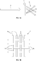
- FIG 1A schematically illustrates how a barrier 1 can be used to form a spray 5 from a jet 3 of water.
- the barrier 1 is a wire mesh.
- a jet 3 is formed when a water supply is forced through a narrow opening, increasing the velocity of the water.
- the jet 3 is directed at the wire mesh 1, which is formed as a grid of wires 7, as shown in Figure 1B .
- the mesh 1 acts to break up the jet 3, to create the spray pattern 5.
- the spray pattern 5 is formed because of the Coanda effect, amongst other things.
- the water from the jet 3 attaches to the curved surfaces of the wires 7 in the mesh 5.
- the water in the jet 3 remains attached to the wires 7 as it passes along the surfaces curved away from the initial direction of the jet 3.
- the water from the jet 3 detaches from the surface of the wire 7 erratically, e.g. at a later time or later position/point. Since the jet 3 is directed across an area of the mesh 1, this happens at a number of points, creating a spray 5.
- the spray 5 has a largely random pattern, as small pressure differences mean the behaviour of the water is not predictable.
- the mesh 1 is formed of a number of wires 7 that pass over and under each other to form an interlaced weave.
- the wires 7 in the mesh 1 are formed of a compliant material such as rubber, and are elastically deformable. Since the wires 7 are elastically deformable, the mesh 1 itself is also elastically deformable.
- the wires 7 can have any shape cross section with curved edges, such that they exhibit the Coanda effect.
- the wires 7 may be circular, or elliptical in cross section.
- the wires 7 may be between 0.1 mm and 10mm, in diameter. Where the wires are not circular, the diameter is measured as the largest diameter.
- the weave is made up of a first set of parallel wires 7a running in a first direction, and a second set of parallel wires 7b running in a second direction, approximately perpendicular to the first direction.
- the first set 7a and second set 7b are interlaced to form the weave.
- Openings 9 are formed between the wires 7. Depending on the tightness of the weave, openings 9 of varying size are formed.
- the openings 9 may be between 0.1 mm and 10 mm in size.
- a mesh 1 could be used to form a spray pattern 5 in an ablutionary fitting.
- An embodiment will now be described in which the mesh 1 is incorporated into a shower head 11.
- the same teaching may be applied to taps, mixer taps, bidets, pull out sprays for showers or sinks (including kitchen sinks), or other types of ablutionary fittings.
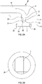
- FIG 2A illustrates an example of a cut-through cross section of a shower head 11 that incorporates a mesh 1 to form a spray 5 as discussed above.
- the shower head 11 is incorporated into a handset 27 (only part is shown).
- the handset 27 may be connected to a hose or other water supply system (not shown), and may be held above a bath or shower tray (not shown).
- the shower head 11 is formed by a housing 15 defining a volume 13.
- a water conduit 17 is provided, to deliver water into the handset 27.
- a nozzle 21 is provided at the end of the conduit 17.
- the nozzle 21 is substantially cylindrical shaped with a flat base 31, and a curved top surface 33, extending in a longitudinal direction.
- the nozzle 21 includes a narrow passage 19, extending between an inlet 35 in the base 31, and an outlet aperture 29 in the top surface 33.
- the passage 19 extends through the nozzle 21, along a centre line C of the nozzle 21.
- the centre line C runs through the centre of the nozzle 21, perpendicular to the base 31.
- the nozzle 21 forms a jet of water 5 directed at an opening 23 in the housing 15 through which the water exits the shower head 11.
- a mesh 1 is provided over the opening 23, to form a spray pattern 5, and is secured in place by a holder 25.
- Figure 2B shows the mesh 1 and holder 25 in end-on view, towards the mesh 1, along the centre line C.
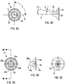
- Figures 2C and 2D show an alternative example for the arrangement of the nozzle 21 and passage 19.
- Figure 2C shows the outer surface 33 of the nozzle 21, in plan view along the centre line C.
- Figure 2D shows a cross section through the nozzle 21 to show the passage 19.
- the passage 19 does not extend centrally through the nozzle 21, and forms a first angle between the passage 19 and the centre line C, when viewed in cross section.
- This first angle is shown as angle a in Figure 2D .
- the first angle is defined between the centre line C and a second axis C′′′.
- the second axis C′′′ extends from the centre of the base 31 of the nozzle 21 (where the centre line C meets the base 31), parallel to the passage 19.
- the first angle may be between 0 degrees and 45 degrees.
- the passage may extend at any circumferential position around the centre line C, measured by a second angle between an origin axis C', perpendicular to the central axis C, and an axis C" perpendicular to the central axis C and passing through the opening 19, in the plane of the opening 19.
- the second angle is shown as angle b in Figure 2C , and can be between 0 and 350 degrees.
- the variation of the first angle and the second angle means that the outlet apertures 29 may be provided at any position on the outer surface 33 of the nozzle 21.
- any suitable shape may be used for the nozzle 21.
- Spray effects can include one or more of the shape profile of a spray, the pressure of a spray, the time varying profile (frequency) of a spray.
- passage 19 and outlet aperture 29, may have any diameter or size between 0.1mm and 10mm.
- the diameter is shown as d in Figure 2D .
- the nozzle 21 is provided with a single outlet aperture 29 in the outer surface 33, and a single passage 19.
- a plurality of passages 19 and outlet apertures 29 may be provided between the inlet 35 on the base 31, and a plurality of outlet apertures 29 in the outer surface 33 of the nozzle 21.
- the nozzle 21 may include any number of outlet apertures 29 in its outer surface 33.
- any one or more of the first angle, second angle and diameter may be varied as discussed above.
- spray effects can include one or more of the shape profile of a spray, the pressure of a spray, the time varying profile (frequency) of a spray.
- the first angle may depend on the size of the outlet aperture 29, such that larger outlet apertures 29 extend further away from the centre line C than smaller outlet apertures 29, or vice versa.
- the second angle of each passage 19 may be arranged such that the outlet apertures 29 are evenly distributed around the surface 33 of the nozzle.
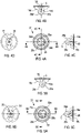
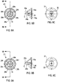
- Figures 3A to 3C show a first example of a nozzle 21 including four outlet apertures 29a-d, such that it forms four jets 3.
- Figure 3A shows the outer surface 33 of the nozzle 21, in plan view along the centre line C.
- Figure 3B shows cross sections through the nozzle 21 to show two of the passages 19a, c, and
- Figure 3C shows the base 31 of the nozzle 21, in plan view along the centre line C.
- each of the passages 19a-d and outlet apertures 29a-d have a diameter of 2.5mm.
- Each of the passages 19a-d is arranged at an angle of 13.7 degrees to the centre line (the first angle).
- the passages 19a-d are arranged so that the apertures 29a-d are evenly distributed around the surface 33 of the nozzle 21. Therefore, the second angle of the first passage 19a is 0 degrees, the second angle of the second passage 19b is 90 degrees, the second angle of the third passage 19c is 180 degrees, and the second angle of the fourth passage is 270 degrees.
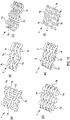
- Figures 4A to 4D show a second example of a nozzle 21 including four outlet apertures 29a-d, such that it forms four jets 3.
- Figure 4A shows the outer surface 33 of the nozzle 21, in plan view along the centre line C.
- Figures 4B and 4C shows cross sections through the nozzle 21 to show the four passages 19a-d, and Figure 4D shows the base 31 of the nozzle 21, in plan view along the centre line C.
- the first passage 19a has a diameter of 3mm
- the second passage 19b has a diameter of 2.5mm
- the third passage 19c has a diameter of 2mm
- the fourth passage 19d has a diameter of 1.5mm.
- the outlet apertures 29a-d are the same size as the passages 19a-d.
- the four passages 19a-d diverge from the centre line C at the first angle.
- the first angle for the first passage 19a is 18.4 degrees
- the first angle for the second passage 19b is 15.4 degrees
- the first angle for the third passage 19c is 12.4 degrees
- the first angle for the fourth passage 19d is 9.4 degrees. Therefore, the smaller outlet apertures 29 are close to the centre of the outer surface 33.
- the passages 19a-d are arranged so that the outlet apertures 29a-d are evenly distributed around the surface 33 of the nozzle 21. Therefore, the second angle of the first passage 19a is 0 degrees, the second angle of the second passage 19b is 90 degrees, the second angle of the third passage 19c is 180 degrees, and the second angle of the fourth passage is 270 degrees.
- Figures 5A to 5D show a third example of a nozzle 21 including four outlet apertures 29a-d, such that it forms four jets 3.
- Figure 5A shows the outer surface 33 of the nozzle 21, in plan view along the centre line C.
- Figures 5B and 5C shows cross sections through the nozzle 21 to show the four passages 19a-d, and Figure 5D shows the base 31 of the nozzle 21, in plan view along the centre line C.
- the first passage 19a has a diameter of 1.5mm
- the second passage 19b has a diameter of 2mm
- the third passage 19c has a diameter of 2.5mm
- the fourth passage 19d has a diameter of 3mm.
- the outlet apertures 29a-d are the same size as the passages 19a-d.
- the four passages 19a-d diverge from the centre line C at the first angle.
- the first angle for the first passage 19a is 18.4 degrees
- the first angle for the second passage 19b is 15.4 degrees
- the first angle for the third passage 19c is 12.4 degrees
- the first angle for the fourth passage 19d is 9.4 degrees. Therefore, the larger outlet apertures 29 are close to the centre of the outer surface 33.
- the passages 19a-d are arranged so that the outlet apertures 29a-d are evenly distributed around the surface 33 of the nozzle 21. Therefore, the second angle of the first passage 19a is 0 degrees, the second angle of the second passage 19b is 90 degrees, the second angle of the third passage 19c is 180 degrees, and the second angle of the fourth passage is 270 degrees.
- Figures 6A to 6D show a fourth example of a nozzle 21 including four outlet apertures 29a-d, such that it forms four jets 3.
- Figure 6A shows the outer surface 33 of the nozzle 21, in plan view along the centre line C.
- Figures 6B and 6C shows cross sections through the nozzle 21 to show the four passages 19a-d, and Figure 6D shows the base 31 of the nozzle 21, in plan view along the centre line C.
- each of the passages 19a-d and outlet apertures 29a-d have a diameter of 2.5mm.
- the four passages 19a-d diverge from the centre line C at the first angle.
- the first angle for the first passage 19a is 18.4 degrees
- the first angle for the second passage 19b is 15.4 degrees
- the first angle for the third passage 19c is 12.4 degrees
- the first angle for the fourth passage 19d is 9.4 degrees. Therefore, the outlet apertures 29 get closer to the centre of the surface 33, as they move around the surface 33.
- the passages 19a-d are arranged so that the outlet apertures 29a-d are evenly distributed around the surface 33 of the nozzle 21. Therefore, the second angle of the first passage 19a is 0 degrees, the second angle of the second passage 19b is 90 degrees, the second angle of the third passage 19c is 180 degrees, and the second angle of the fourth passage is 270 degrees.
- Figures 7A to 7C show a first example of a nozzle 21 including six outlet apertures 29a-f, such that it forms six jets 3.
- Figure 7A shows the outer surface 33 of the nozzle 21, in plan view along the centre line C.
- Figure 7B shows cross sections through the nozzle 21 to show the passages 19a-f, and
- Figure 7C shows the base 31 of the nozzle 21, in plan view along the centre line C.
- each of the passages 19a-f and outlet apertures 29a-f have a diameter of 2mm.
- Each of the passages 29a-f is also arranged at an angle of 13.7 degrees to the centre line (the first angle).
- the passages 19a-f are arranged so that the outlet apertures 29a-f are evenly distributed around the surface 33 of the nozzle 21. Therefore, the second angle of the first passage 19a is 0 degrees, the second angle of the second passage 19b is 60 degrees, the second angle of the third passage 19c is 120 degrees, the second angle of the fourth passage 19d is 180 degrees, the second angle of the fifth passage 19e is 240 degrees, and the second angle of the sixth passage 19f is 300 degrees.
- Figures 8A to 8C show a second example of a nozzle 21 including six outlet apertures 29a-f, such that it forms six jets 3.
- Figure 8A shows the outer surface 33 of the nozzle 21, in plan view along the centre line C.
- Figure 8B shows cross sections through the nozzle to show the passages 19a-f, and
- Figure 8C shows the base 31 of the nozzle 21, in plan view along the centre line C.
- the outlet apertures 29a-d are arranged in two groups.
- the first group is formed by the first 29a, second 29b and third 29c outlet apertures.
- the second group is formed by the fourth 29d, fifth 29e and sixth 29f outlet apertures.
- the outlet apertures in the first group 29a-c have a diameter of 1.8mm, and are arranged at an angle of 4.5 degrees to the centre line (the first angle).
- the outlet apertures in the second group 29d-f have a diameter of 2.5mm, and are arranged at an angle of 13.7 degrees to the centre line (the first angle).
- the passages 19a-f are arranged so that the outlet apertures 29a-f are evenly distributed around the surface 33 of the nozzle 21, with the first and second groups alternating. Therefore, the second angle of the first passage 19a is 0 degrees, the second angle of the second passage 19b is 120 degrees, the second angle of the third passage 19c is 240 degrees, the second angle of the fourth passage 19d is 60 degrees, the second angle of the fifth passage 19e is 180 degrees, and the second angle of the sixth passage 19f is 300 degrees.
- Figures 9A to 9C show a first third of a nozzle 21 including six outlet apertures 29a-f, such that it forms six jets 3.
- Figure 9A shows the outer surface 33 of the nozzle 21, in plan view along the centre line C.
- Figure 9B shows cross sections through the nozzle 21 to show the passages 19a-f, and
- Figure 9C shows the base 31 of the nozzle 21, in plan view along the centre line C.
- the outlet apertures 29 have a diameter of 0.85mm.
- the outlet apertures 29a-f are arranged in two groups.
- the first group is formed by the first 29a, second 29b and third 29c outlet apertures.
- the second group is formed by the fourth 29d, fifth 29e and sixth 29f outlet apertures.
- the outlet apertures in the first group 29a-c are arranged at an angle of 4.5 degrees to the centre line (the first angle).
- the outlet apertures in the second group 29d-f are arranged at an angle of 13.7 degrees to the centre line (the first angle).
- the passages 19a-f are arranged so that the outlet apertures 29a-f are evenly distributed around the surface 33 of the nozzle 21, with the first and second groups alternating. Therefore, the second angle of the first passage 19a is 0 degrees, the second angle of the second passage 19b is 120 degrees, the second angle of the third passage 19c is 240 degrees, the second angle of the fourth passage 19d is 60 degrees, the second angle of the fifth passage 19e is 180 degrees, and the second angle of the sixth passage 19f is 300 degrees.
- a recessed inlet area 35 is formed in the base 31.
- Each of the passageways 19a-f opens into the inlet area 35, such that they do not intersect. This provides smooth jets 3 for delivery to the mesh(es) 1.
- the passageways 19a-f may intersect before the inlet area 35.
- the or each passageway 19a-f may be offset relative to the centre line, C, i.e. the second axis C'" does not extend from the centre of the base 31 of the nozzle 21.
- the outlet apertures 29 and passages 19 arc circular.
- the outlet apertures 29 may have different shapes, such as elongate oval openings, triangular, square and other suitable shapes.
- all the outlet apertures 29 have the same shape, however, this need not be the case.
- the nozzles 21 discussed above are given by way of example only. It will be appreciated that, as discussed previously, the nozzle 21 may include any number of openings 29 and passageways 19. Furthermore, for each passageway 19, the first angle may be between 0 degrees and 45 degrees, and the second angle may be between 0 and 350 degrees.
- the sides of the passageways 19 are parallel to each other, such that the diameter of the passageway 19 is the same along its length.
- the passageways may narrow or widen towards the outlet apertures 29.
- the nozzle includes a curved top surface 33.
- the top surface 33 may also be flat, angular, or any other shape.
- the surface 33 may be modified near the outlet apertures 29.
- the portion of the body adjacent the aperture may partially obstruct the flow of water out of the aperture.
- the nozzle 21 may be modified so that in the region of the outlet apertures 29, the top surface 33 of the nozzle 21 is flattened so that there is a region of the surface 33 which is perpendicular to the direction of the passageway 19.
- the nozzle may be shaped in any manner so as not to introduce turbulence into the flow through the nozzle 21. It will also be appreciated that this feature is optional.
- a single nozzle 21 is provided. However, it will be appreciated that in some examples, multiple nozzles 21 may be provided.
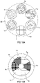
- Figures 10(a) to (f) show examples of different weave patterns that may be used in the mesh 1.
- the mesh 1 is sized to fit into the whole of the opening 23 of the shower head 11, as shown in Figure 2B , but Figures 10(a) to 3(f) only show a section, to illustrate the weaves.
- Figure 10(a) illustrates an example of a twilled weave.
- each wire in the second set 7b passes under two or more wires of the first set 7a, and then over one or more wires in the first set 7b.
- the adjacent wires in the second set 7b follow the same pattern, but the overlap is shifted along by one wire 7a.
- the wires 7 are all of the same size and shape, and each wire in the second set 7b passes over two wires in the first set 7a, then under two wires in the first set 7a.
- the shift is such that where a wire in the second set 7b goes under two wires of the first set 7a, the next wire in the second set 7b goes over the first of the wires in the first set 7a, under the next two wires in the first set 7a, and over the fourth. This shift continues down the pattern to give a diagonal effect.
- Figure 10(b), (c) and (d) illustrate examples of a plain weave, a betamesh weave and a Robusta weave respectively.
- each wire in the second set 7b passes over one wire in the first set 7a, then under a wire in the first set 7a. Adjacent wires in the second set 7b alternate in pattern. In the example shown, the wires 7 are all of the same shape.
- the wires in the first set 7a and the wires in the second set 7b are the same size.
- the wires in the second set 7b gradually increase in size, relative to the wires in the first set 7a, for the betamesh and Robusta.
- Figure 10(e) illustrates an example of a duplex weave. This is similar to the plain weave or twill weave, except each wire in the second set 7a passes over two wires in the first set 7a and then under two wires in the first set 7b, and the shift between adjacent wires in the second set 7b is doubled, so that the pattern of the wires in the second set 7b alternates rather than steps.
- Figure 10(f) illustrates an example of a square weave. This is the same as the plain weave, with the spacing between the wires 7 increased to provide larger openings 9.
- weave patterns given above are given by way of example only. It will be appreciated that any suitable weave pattern may be used.
- first set of wires 7a and second set of wires 7b are the same shape and material, although the size varies. It will be appreciated that the different sets 7a,b may comprise wires of different shape and/or different material.
- the first set of wires 7a is perpendicular to the second set of wires 7b. It will be appreciated that this may not necessarily be the case. Furthermore, in the above example, the wires in the first set of wires 7a are all parallel to each other, and the wires in the second set of wires 7b are all parallel to each other. It will also be appreciated that this may not necessarily be the case.
- the wires may taper towards and/or away from each other. This creates a variation in the opening 9 size across the mesh 1.
- the mesh 1 is a two dimensional structure (not considering the variation due to the weave).
- the mesh 1 may be shaped in three dimensions.
- Figures 11(a) to (d) illustrate different examples of three dimensional shaped meshes 1.
- the mesh 1 may be dome shaped, as in Figure 11(c) and 11(d) , conical, cylindrical, a tapered cylinder, top hat, or pyramidal, as in Figure 11(b) .
- the three dimensional shape may be less regular, such as a star, as in Figure 11(a) , or flower shaped.
- the mesh 1 may be rippled.
- the three dimensional mesh 1 may be of constant width along its length, or it may taper inwardly or outwardly from the base to the tip.
- the entire mesh 1 may be shaped as described above.
- the mesh 1 may include one or more planar regions, with the three dimensional pattern projecting out from other regions.
- the mesh 1 may include a single domed region, or a number of bumps.
- the spray 5 formed where the jet 3 passes the three dimensional region will have different characteristics to the spray 5 formed in the planar region.
- the jet 3 may pass through both planar and three dimensional regions at the same time, so different regions of the spray have different characteristics, or may only pass through one of the regions at a time.
- the three dimensional shape of the mesh may project towards or away from the nozzle 21 in the shower head 11.
- the three dimensional shape may be derived as the permanent structure of the mesh 1. This may be achieved using a support frame or anchor points (not shown) to hold the shape of the mesh 1.
- the mesh 1 forms a circular disc.
- the mesh may be any shape.
- the mesh 1 may be in the form of an annular ring.
- the nozzle 21 may be arranged to rotate about the centre line C. In order to rotate, the nozzle 21 must be mounted in such a manner that in can rotate about the centre line C.
- the nozzle 21 may be mounted on a shaft (not shown) secured to the shower head 11.
- the rotation is driven by a turbine (not shown) driven by the incoming water.
- the turbine may be of the axial or radial type.
- the velocity of the water and distribution of the passageways 19 drives the rotation.
- the turbine is positioned upstream of the nozzle 21, so the water drives the turbine before entering the nozzle 21.
- lobes are provided in the passageways 19.
- the lobes are formed from formations in the passageways 19 and are asymmetric in structure. Therefore, when water is incident on the lobes, it causes the nozzle 21 to rotate.
- rotation may be driven by a motor or the like (not shown).
- Rotation of the nozzle 21 can create different patterns in the spray 5.
- the speed of rotation may also be controlled to vary the pattern of the spray 5.
- the speed of rotation may be varied by varying the water velocity, gearing systems and the like.
- Means for controlling water velocity is known.
- the water velocity may be controlled by gradually opening and closing a valve leading to the shower head 11.
- the speed of rotation may also be altered by varying the amount of water hitting the turbine, or by varying the number and size of blades and/or a gearing system.
- the speed of rotation may also be controlled by varying the speed of the motor.
- the nozzle 21 simply rotates around its central axis C.
- the rotation may be a continuous rotation around a single axis in either direction.
- the nozzle may rotate back and forth to create an oscillation.
- the movement may include both rotation and oscillation to produce an orbital motion.
- each nozzle 21 may be able to move independently of the others. Therefore, the nozzles 21 may rotate in opposite directions at the same or different speeds. In other examples, the nozzles may rotate in the same direction.
- Rotation about the central axis is just one way in which the nozzle 21 may move.
- the nozzle 21 may rotated about different axes.
- the entire nozzle 21 may move in a translation movement.
- the translation movement may be in any direction or path.
- the entire nozzle may move in a circle.
- the nozzle 21 may wobble about a central point.
- the nozzle 21 may move in one or more of the ways discussed above at once. In addition to the speed of rotation, the speed of all of the movements may be varied. The movements are all caused by the water velocity, and so altering the water velocity can control the speed of movement.
- the mesh 1 may also be arranged to rotate about the central axis.
- the mesh 1 may also wobble, oscillate or move in other ways.
- the movement of the mesh 1 can be driven in the same way as the movement of the nozzle 21.
- a driving system may be needed to couple the mesh to the water stream that drives the rotation.
- the movement of the mesh is optional, and may be provided instead of or as well as the movement of the nozzle 21. As with movement of the nozzle, movement of the mesh 1 will alter the pattern in the spray 5.
- the mesh 1 is resiliently deformable in some embodiments.
- the mesh 1 may be planar when not in use, and deformed by the pressure of the jet 3, to provide a three dimensional state. Once the jet 3 is removed, the mesh 1 reverts to the planar state. This may still use a support frame, or not.
- the elasticity of the wires 7 and tightness of the weave can be used to control whether, and by how much, the mesh 1 deforms.
- the deformation may be local to the region in which the jet 5 hits the mesh 1. Therefore, in examples with a rotating jet 5, the deformation may create a wave effect in the mesh 1, which in turn also affects the spray 5. In other examples, the mesh 1 may deform into shapes that in part form the pattern of the spray.
- the mesh 1 is mounted in the shower head 11 by a holder 25.
- a spacer mechanism (not shown) is provided to alter the distance between the mesh 1 and the nozzle 21, upon user actuation.
- the distance between the mesh 1 and the nozzle 21 may be between 0.1mm and 500mm. In some examples, the distance may be between 0.1mm and 200mm. Optionally, the distance may be between 0.1mm and 100mm.
- the spacer mechanism may be provided by any suitable mechanism such as a cam mechanism, a screw thread interacting with an engaging screw thread in the housing 15 of the shower head 11, a lever or a ratchet.
- the spacer mechanism moves the mesh 1 to alter the distance between the nozzle 21 and the mesh 1.
- the spacer mechanism may move the nozzle 21.
- the pattern of the spray 5 may have one or more focal and or divergent points, where the separate streams in the spray 5 converge, diverge or create some other effect. Varying the distance between the nozzle 21 and the mesh 1 will vary these point(s).
- a planar or 3D mesh defines a plane.
- the plane of the mesh 1 is perpendicular to the centreline C of the nozzle 21. In other examples, this may not be this case, or the angle between the centreline C of the nozzle 21 and the plane of the mesh 1 can be varied. This may be tilting the nozzle 21 and/or the mesh 1.
- Figure 12 illustrates an alternative arrangement for the shower head 11.
- first mesh 1a in the stream of the jet 3 from the nozzle 21.
- the first mesh 1 breaks the jet 3 into a smaller spray 5.
- the resulting spray 5 from the first mesh 1a hits a second mesh 1b, which further breaks down the spray 5.
- a series of two meshes 1a, b is formed.
- the meshes 1a, b in the series act to sequentially break the jet into a fine spray 5.
- the first mesh 1a breaks the jet 3 into a spray 5
- the second mesh 1b breaks the spray 5 into a finer spray 5.
- the meshes 1a, b in the series may be of different weave and/or may have different size openings 9 and/or may be formed of different size and shape wires 7.
- the meshes 1 a, b may be the same.
- the meshes 1a, b may be aligned, so that the first set of wires 7a in each mesh 1a, b in the series are parallel.
- the meshes 1a, b may be rotated around an axis through the centre of the series (i.e. down the path the stream 3 follows) relative to one another.
- the distance between the first mesh 1a and the nozzle 21 is shown by x in Figure 12 .
- x should be at least 0.1mm, and at most 500mm.
- the distance between the first mesh 1a and the second mesh 1b is shown by y in Figure 12 .
- y should be at least 0.1mm. At most x + y is also 500mm, so that the second mesh 1b is at most 500mm from the nozzle 21.
- x and y may both be between 0.1mm and 200mm.
- x and y may be between 0.1mm and 100mm.
- One or both of the meshes 1a, b may be moveable, in a similar manner as discussed above. This further alters the convergent and divergent effects of the spray 5, with a first spacer mechanism provided to move the first mesh 1a, and a second spacer mechanism provided to move the second mesh.
- the spacer mechanisms provide a system for moving the meshes 1a,b and varying the spray 5 characteristics.
- each mesh 1 may be moved independently, such that both of the meshes 1a, b are moveable relative to each other, and the nozzle 21.
- the meshes 1a, b may be in a fixed relationship so that they move together as a unit, and only x is varied.
- the minimum and maximum distances between the first mesh 1a and the nozzle 21, are as discussed above.
- one of the meshes 1a, b may be moveable, relative to the nozzle 21 and the other meshes 1a, b, whilst the other mesh 1a, b is fixed in position.
- the moveable mesh 1a, b may the mesh 1a closest to the nozzle 21. In other cases, it may the mesh 1b further from the nozzle 21.
- the minimum and maximum distance between the first mesh 1a and the nozzle 21, the minimum distance between the meshes 1a, b and the maximum distance between the nozzle 21 and the second mesh 1b are as discussed above.
- the nozzle 21 may be the nozzle 21 that is moved, instead of or as well as than the meshes 1a, b, so the distance between the nozzle 21 and the barrier(s) can also be varied by moving the nozzle 21.
- the distance (x) between the barrier 1 and the nozzle 21 may be varied by moving the nozzle 21 and/or by moving the barrier 1.
- the spacing between each of the barriers 1 may be varied by moving the barriers 1.
- the nozzle 21 may also optionally be moved to vary the distance between the nozzle 21 and the barriers 1.
- the spacing between the barriers 1 may be fixed, but the distance between the nozzle 21 and the barriers 1 can be varied by moving the nozzle 21 and/or moving the barriers 1 as a set.
- the planes of the meshes 1 are parallel to each other, and perpendicular to the centreline C of the nozzle. In other examples, the meshes 1 may be arranged at different angles to each other, and/or to the centreline of the nozzle 21.
- any number of meshes 1 may be provided in a series, and some or all of the meshes 1 may be moveable via spacer means, as discussed above, to vary the spray 5.
- the minimum and maximum distance between the first mesh 1a and the nozzle 21, the minimum distance between the meshes 1 is as discussed above.
- the spacing between the meshes 1 is as discussed above. As discussed above, where meshes 1 are provided in a series, they act to sequentially break down the spray 5.
- Any suitable nozzle 21 may be used with a series of meshes 1.
- the holder 25 there is a single mesh 1 in each plane. In other words, the jet 3 only passes through a single mesh 1 at any given distance from the nozzle 21. It will be appreciated that in some examples, as shown in Figure 13A , the holder 25 may include a number of different meshes 1a-f arranged over the surface of the holder 25.
- Each of the meshes 1 in the group may have a different weave and/or opening size and/or wire size, such that each mesh 1 creates a different effect in the spray 5.
- some of the meshes 1 may be three dimensional, or include three dimensional areas.
- one or more nozzles 21 may be provided and/or arranged such that water is provided through all meshes 1a-f, creating a variety of patterns.
- nozzle(s) 21 may be provided and/or arranged such that a chosen one or more of the meshes 1a-f held in the holder 25 is used, without using all meshes 1.
- the holder 25 may be arranged to move the meshes 1 to bring the selected mesh(es) 1 into register with the nozzle(s) 21. This may be through any suitable mechanism such as a cam mechanism, a screw thread, a lever or a ratchet.
- one or more of the meshes may be omitted, so that the shower head opens directly to the nozzle 21 at that point.
- each of the meshes 1a-f may be able to tilt relative to the plane in which they are held, or may be fixed in a tilted position.
- each holder 25 may be arranged in series, each having one or more meshes 1.
- each holder 25 may be arranged to select one of the meshes 1 for the stream 3 of water to pass through.
- the mesh 1 from the first holder 25 may be independently selected from the mesh 1 from the second holder 25. Therefore, in the example where each holder 25 includes six meshes 1, thirty six different combinations are provided, each providing a different pattern in the output spray 5.
- the distance between the holders 25 may be altered, as discussed above for single meshes 1 in series.
- one of the holders 25, for example the first, may have a single mesh 1.
- the mesh 1 may be formed of a single continuous mesh 1, with regions 1a-f having different weave and/or opening size and/or wire size, such that the different regions produce different effects in the spray 5.
- some of the regions 1a-f may be three dimensional, or include three dimensional areas.
- the nozzles 21 and regions may be arranged such that the jet 3 only passes through a single region, or a subset of the regions, at once, and the holder 25 may be moveable in some way to bring the different regions into register with the water. As discussed above, one or more of the regions may not include any mesh 1.
- the shower head 11 may include an air induction feature that mixes the water stream from the nozzle 21 with air. This reduces the consumption of water.
- the air induction feature itself may affect the spray cffcct.
- the mesh 1 is described as being formed of interlaced wires. It will, however, be appreciated, however, that this is just one example of a mesh 1.
- the wires in the first direction 7a, and the wires in the second direction 7b may be arranged in different planes, provided adjacent to one another.
- the holder 25 may be arranged to allow the separate planes to be moved apart. This allows any material that is potentially clogging the mesh 1 to be removed.
- an anti-clog feature may be provided by having two or more relatively coarse meshes placed close together to provide the same effect as a single relatively fine mesh arrangement.
- the coarse meshes can be moved apart and water/fluid allowed to run through to release unwanted debris from the entire arrangement. It is easier for unwanted debris to pass through each separated coarse mesh while moved apart, than to pass through the effectively fine mesh when the constituent meshes are close together.
- the mesh may be provided by any sheet of material with holes formed in it, where the edge of the holes have a curved radius, arranged to encourage the Coanda effect.
- the mesh may be formed by etching, punching, drilling, laser cutting, or 3D printing (or additive manufacturing).
- a mesh 1 is used to break up a jet 3 and form a spray 5 based on the Coanda effect.
- the mesh 1 may be arranged to discourage the Coanda effect, for example by using square section wires.
- the mesh 1 is just one example of a barrier that can be used to break up a jet into a spray, and direct the resulting streams in the spray.
- any suitable dispersing barrier atomiser
- the barrier could comprise a plate, having through holes arranged at different angles to the plane of the surface of the barrier. This acts to break up the jet 3 and direct the resulting streams in the spray.
- the holder 25 is fixed in the shower head 11. However, it will be appreciated that this may not always be the case, and the holder 25 may be removably detachable in order to allow the holder 25 with the mesh 1 to be removed, and cleaned, or a different mesh 1 to be provided.
- the holder 25 may be made removable by any suitable means, such as screw threads, bayonet, clip fits, friction fit, snap fit and the like.
- the nozzle(s) 21 may be arranged so that the jet(s) 3 can be directed at a particular location on the mesh 1. This could be by moving the nozzle 21, or changing the angle of the nozzle 21. This can be controlled by a user, and may be used to form 3D shapes in different regions of a compliant mesh 1. The 3D shapes may be ripples, ridges or valleys, or any of the shapes described in relation to Figure 11 . This can also be used to direct the jet 3 to a particular mesh 1, or region of the mesh 1 (such as a 3D region). This can be used instead of or as well as movement of the selected mesh(es) 1 into register with the jet 3, as discussed above.
- the wires 7 are made from rubber. It will be appreciated that the wires 7 may be formed of any suitable resiliently deformable or compliant material, and may be elastic or not.
- the mesh 1 is held in a holder 25 separate to the housing 15 of the shower head 11. It will be appreciated that this is by way of example only. Any suitable holder 25 may be used to provide a means for holding the mesh 1.
- the shower head 11 and holder 25 are arranged to allow the distance between the nozzle 21 and mesh(es) 1 to be varied. It will be appreciated that any suitable mechanism may be used to modify this distance, and the holder 25 may be arranged in any way that allows the distance to be modified. Furthermore, in some examples, the distance between the nozzle 21 and the mesh 1 may be fixed, such that it cannot be varied.
- the construction of the shower head 11 discussed above is by way of example only.
- the shower head 11 may be of any suitable construction.
- the shower head 11 may be incorporated into a larger handset 27.
- the shower head 11 may be separate to the handset 27, and fixable by screw threads or other mechanism, or may be integrally incorporated into the handset 27.
- the shower head 11 may be fixed directly to a wall or ceiling water delivery outlet (not shown), and is not part of a handset 27.
- the water passes through the mesh 1 in the form of a jet 3.
- a jet 3 is a stream of water that is projected through a nozzle 21 aperture to focus it and usually results in an increase in velocity.
- the jet 3 is created by a nozzle 21.
- the jet may be created in any suitable way.
- the mesh(es) 1 may be used with any directed stream of water, not necessarily just a jet 3.
Landscapes
- Health & Medical Sciences (AREA)
- Life Sciences & Earth Sciences (AREA)
- Engineering & Computer Science (AREA)
- Hydrology & Water Resources (AREA)
- Public Health (AREA)
- Water Supply & Treatment (AREA)
- Nozzles (AREA)
Claims (15)
- Wascharmatur (11), die Folgendes einschließt:einen Auslass (29) zum Bereitstellen eines Wasserstroms (3); undeine Dispersionsbarriere (1), die im Weg des Wasserstroms (3) eingerichtet ist, und so angeordnet ist, dass der Wasserstrom (3) beim Passieren durch die Dispersionsbarriere (1) in eine Vielzahl kleinerer Ströme aufgespalten wird, die einen Sprühnebel (5) bilden, wobei die kleineren Ströme zumindest teilweise von der Dispersionsbarriere (1) gelenkt werden,dadurch gekennzeichnet, dass der Auslass (29) so eingerichtet ist, dass er sich um eine Achse dreht, die im Wesentlichen senkrecht zu einer Ebene der Dispersionsbarriere (1) verläuft, und wobei die Drehung des Auslasses (29) unabhängig von jeder Bewegung der Dispersionsbarriere (1) ist.
- Wascharmatur (11) nach Anspruch 1, wobei die Dispersionsbarriere (1) ein Netz umfasst.
- Wascharmatur (11) nach Anspruch 2, wobei das Netz aus einem ersten Satz von im Wesentlichen parallelen Drähten (7a), die in einer ersten Richtung verlaufen, und einem zweiten Satz von im Wesentlichen parallelen Drähten (7b), die in einer zweiten Richtung verlaufen, die im Wesentlichen senkrecht zur ersten Richtung verläuft, gebildet ist; wobei der erste Satz von Drähten (7a) Drähte (7) mit einem ersten Formquerschnitt und einer ersten Größe umfasst und der zweite Satz von Drähten (7b) Drähte (7) mit einem zweiten Formquerschnitt und einer zweiten Größe umfasst, wobei die Größe der Drähte (7) als die größte Abmessung des Drahts gemessen wird; und wobei der erste Formquerschnitt sich von dem zweiten Formquerschnitt unterscheidet und/oder die erste Größe sich von der zweiten Größe unterscheidet.
- Wascharmatur (11) nach einem vorstehenden Anspruch, wobei die Drehung des Auslasses (29) und/oder der Dispersionsbarriere (1) eine kontinuierliche Drehung im oder gegen den Uhrzeigersinn um die Achse oder eine Oszillation um die Achse oder eine Kombination aus beidem einschließt, um eine Orbitalbewegung zu erzeugen.
- Wascharmatur (11) nach einem vorstehenden Anspruch, wobei sich der Auslass (29) und/oder die Dispersionsbarriere (1) mit unterschiedlichen, von einem Benutzer steuerbaren Geschwindigkeiten bewegen kann und wobei die Bewegungsgeschwindigkeit zumindest teilweise die Eigenschaften und das Muster des Sprühnebels (5) steuert.
- Wascharmatur (11) nach einem vorstehenden Anspruch, wobei der Auslass (29) eine Düse (21) umfasst, die eine Auslassöffnung (29a-d) aufweist, die so eingerichtet ist, dass sie den Wasserstrom (3) als einen Strahl bildet.
- Wascharmatur (11) nach Anspruch 4, wobei die Düse (21) eine Vielzahl von Auslassöffnungen (29a-d) einschließt, wobei jede Auslassöffnung (29a-d) so eingerichtet ist, dass sie einen Strahl bereitstellt, wobei die Anzahl der Auslassöffnungen (29a-d) zumindest teilweise die Eigenschaften und das Muster des Sprühnebels (5) bestimmt, wobei optional:
jede Auslassöffnung (29a-d) einen ersten Winkel zwischen einer ersten Achse senkrecht zu einer durch die Dispersionsbarriere (1) definierten Ebene und einer Achse senkrecht zur Auslassöffnung (29a-d) bildet, und zumindest einige der Vielzahl von Auslassöffnungen (29a-d) unterschiedliche erste Winkel zueinander bilden, wobei der erste Winkel jeder Auslassöffnung (29a-d) zumindest teilweise die Eigenschaften und das Muster des Sprühnebels (5) bestimmt; und/oder die Umfangsposition jeder Auslassöffnung (29a-d) durch einen zweiten Winkel beschrieben wird, der als Drehwinkel in der Ebene der Dispersionsbarriere (1) definiert ist, wobei zumindest einige der Vielzahl von Auslassöffnungen (29a-d) unterschiedliche zweite Winkel zueinander bilden, wobei der zweite Winkel jeder Auslassöffnung (29a-d) zumindest teilweise die Eigenschaften und das Muster des Sprühnebels (5) bestimmt. - Wascharmatur (11) nach einem vorstehenden Anspruch, wobei die Dispersionsbarriere (1) von dem Auslass (29) beabstandet ist und die Wascharmatur (11) erste Abstandshaltermittel umfasst, die so eingerichtet sind, dass sie den Abstand zwischen der Dispersionsbarriere (1) und dem Auslass (29) verändern, wobei der Abstand, in dem die Dispersionsbarriere (1) vor dem Auslass (29) gehalten wird, zumindest teilweise die Eigenschaften und das Muster des Sprühnebels (5) bestimmt.
- Wascharmatur (11) nach einem vorstehenden Anspruch, umfassend zwei oder mehr Dispersionsbarrieren (1a-f), die aufeinanderfolgend eingerichtet sind, sodass die Flüssigkeit durch die Dispersionsbarrieren (1a-f) in Reihe passiert, wobei optional mindestens einige der Dispersionsbarrieren (1a-f) nicht parallel zueinander sind.
- Wascharmatur (11) nach Anspruch 9, die zweite Abstandshaltermittel zum Verändern des Abstands zwischen den Dispersionsbarrieren (1a-f) einschließt, wobei der Abstand zwischen den Dispersionsbarrieren (1a-f) zumindest teilweise die Eigenschaften und das Muster des Sprühnebels (5) bestimmt.
- Wascharmatur (11) nach einem vorstehenden Anspruch, umfassend zwei oder mehr Dispersionsbarrieren (1a-f), die in der gleichen Ebene eingerichtet sind, wobei die zwei oder mehr Dispersionsbarrieren (1a-f) in dergleichen Ebene unterschiedliche Muster in dem Sprühnebel (5) bilden, wobei die Wascharmatur (11) optional Mittel zum Auswählen einer der zwei oder mehr Dispersionsbarrieren (1a-f) einschließt, die in der gleichen Ebene eingerichtet sind, sodass der Flüssigkeitsstrom durch die ausgewählte Dispersionsbarriere (1a-f) passiert.
- Wascharmatur (11) nach Anspruch 11, wobei ein erster Satz von Dispersionsbarrieren (1a-f) in einer ersten Ebene eingerichtet ist und ein zweiter Satz von Dispersionsbarrieren (1a-f) in einer zweiten Ebene eingerichtet ist, sodass eine ausgewählte Dispersionsbarriere aus dem ersten Satz und eine ausgewählte Dispersionsbarriere (1a-f) aus dem zweiten Satz aufeinanderfolgend eingerichtet sind, sodass Flüssigkeit durch die ausgewählten Dispersionsbarrieren (1a-f) in Reihe passiert.
- Wascharmatur (11) nach einem vorstehenden Anspruch, wobei sich der Auslass (29) dreht, während die Dispersionsbarriere (1) feststehend ist.
- Wascharmatur (11) nach einem vorstehenden Anspruch, wobei der Auslass (29) und die Dispersionsbarriere (1) so eingerichtet sind, dass sie sich um eine Achse drehen, die im Wesentlichen senkrecht zu einer Ebene der Dispersionsbarriere (1) verläuft, sodass eine relative Drehung der Dispersionsbarriere (1) und des Auslasses (29) stattfindet.
- Wascharmatur (11) nach einem vorstehenden Anspruch, wobei der Auslass (29) und die Dispersionsbarriere (1) so eingerichtet sind, dass sie sich während der Verwendung der Wascharmatur (11) um eine Achse drehen, die im Wesentlichen senkrecht zu einer Ebene der Dispersionsbarriere (1) verläuft.
Applications Claiming Priority (2)
| Application Number | Priority Date | Filing Date | Title |
|---|---|---|---|
| GB1708850.1A GB2563076B (en) | 2017-06-02 | 2017-06-02 | Ablutionary fitting |
| PCT/GB2018/051484 WO2018220379A1 (en) | 2017-06-02 | 2018-05-31 | Ablutionary fitting |
Publications (3)
| Publication Number | Publication Date |
|---|---|
| EP3630366A1 EP3630366A1 (de) | 2020-04-08 |
| EP3630366B1 true EP3630366B1 (de) | 2022-11-02 |
| EP3630366B8 EP3630366B8 (de) | 2022-12-07 |
Family
ID=59349757
Family Applications (1)
| Application Number | Title | Priority Date | Filing Date |
|---|---|---|---|
| EP18730064.5A Active EP3630366B8 (de) | 2017-06-02 | 2018-05-31 | Wascharmatur |
Country Status (5)
| Country | Link |
|---|---|
| US (1) | US12366059B2 (de) |
| EP (1) | EP3630366B8 (de) |
| CN (1) | CN110709170A (de) |
| GB (1) | GB2563076B (de) |
| WO (1) | WO2018220379A1 (de) |
Families Citing this family (3)
| Publication number | Priority date | Publication date | Assignee | Title |
|---|---|---|---|---|
| CN119365657A (zh) * | 2022-05-06 | 2025-01-24 | 纽珀有限公司 | 卫生嵌件 |
| DE202022102502U1 (de) * | 2022-05-06 | 2023-08-21 | Neoperl Gmbh | Sanitäres Einsetzteil |
| US11660622B1 (en) * | 2022-10-20 | 2023-05-30 | Jiafu Feng | Faucet outlet screen filter |
Family Cites Families (26)
| Publication number | Priority date | Publication date | Assignee | Title |
|---|---|---|---|---|
| US2974877A (en) * | 1958-10-13 | 1961-03-14 | Rain Jet Corp | Shower heads |
| US3633824A (en) * | 1969-07-08 | 1972-01-11 | Elic P Aghnides | Spray-producing device in which the output jets are aerated |
| US3647144A (en) * | 1970-03-31 | 1972-03-07 | American Standard Inc | Swivel spray apparatus |
| US3791584A (en) * | 1972-08-25 | 1974-02-12 | Rain Jet Corp | Shower head |
| US4398669A (en) * | 1977-05-09 | 1983-08-16 | Teledyne Industries, Inc. | Fluid-spray discharge apparatus |
| JP3745779B2 (ja) * | 1993-09-28 | 2006-02-15 | 三機工業株式会社 | 水噴霧式空気浄化装置 |
| CN2282937Y (zh) * | 1995-08-31 | 1998-06-03 | 杨延相 | 可变喷孔截面积的喷雾淋浴喷头 |
| WO1997030619A1 (en) * | 1996-02-26 | 1997-08-28 | Matsushita Electric Industrial Co., Ltd. | Shower bath apparatus and spray nozzle |
| US6199771B1 (en) * | 1998-11-16 | 2001-03-13 | Moen Incorporated | Single chamber spray head with moving nozzle |
| US6245390B1 (en) * | 1999-09-10 | 2001-06-12 | Viatcheslav Baranovski | High-velocity thermal spray apparatus and method of forming materials |
| JP2002010942A (ja) * | 2000-06-29 | 2002-01-15 | Matsushita Electric Ind Co Ltd | シャワー装置 |
| CN2471420Y (zh) * | 2001-04-24 | 2002-01-16 | 郑建栋 | 一种多用途喷嘴 |
| US6719218B2 (en) * | 2001-06-25 | 2004-04-13 | Moen Incorporated | Multiple discharge shower head with revolving nozzle |
| US7111795B2 (en) * | 2004-05-14 | 2006-09-26 | Waxman Consumer Products Group, Inc. | Revolving spray shower head |
| ITMN20040015A1 (it) * | 2004-07-13 | 2004-10-13 | Bpa Srl | Regolatore di flusso |
| US8794543B2 (en) * | 2006-12-28 | 2014-08-05 | Water Pik, Inc. | Low-speed pulsating showerhead |
| CN102036643B (zh) * | 2008-05-20 | 2015-04-22 | 霍氏公司 | 一种紧急洗眼装置 |
| CN201446027U (zh) * | 2009-07-22 | 2010-05-05 | 余泽龙 | 一种具有多旋转按摩水柱的浴缸用按摩喷头 |
| CN101879483B (zh) * | 2010-01-27 | 2012-05-23 | 厦门松霖科技有限公司 | 折叠翻盖花洒 |
| CN202015664U (zh) * | 2010-12-01 | 2011-10-26 | 余章军 | 一种旋转水花的花洒 |
| CN202171044U (zh) * | 2011-08-18 | 2012-03-21 | 孙洪昌 | 节水方便喷雾洗脸专用水龙头 |
| WO2014142766A1 (en) * | 2013-03-12 | 2014-09-18 | Jeremić Dragan | Insert with rotating mesh and rotating mesh for aerators in sanitary batteries |
| DE102013207679B3 (de) * | 2013-04-26 | 2014-10-16 | Hansgrohe Se | Brausekopf mit drehbeweglicher Steuerscheibe |
| CN203737452U (zh) * | 2014-03-28 | 2014-07-30 | 浙江志高洁具有限公司 | 一种喷雾龙头嘴 |
| EP3265234B1 (de) * | 2015-03-06 | 2021-04-14 | Husqvarna AB | Sprühvorrichtung |
| CN106988384B (zh) * | 2017-05-09 | 2023-03-14 | 李军 | 射束起泡器 |
-
2017
- 2017-06-02 GB GB1708850.1A patent/GB2563076B/en active Active
-
2018
- 2018-05-31 EP EP18730064.5A patent/EP3630366B8/de active Active
- 2018-05-31 WO PCT/GB2018/051484 patent/WO2018220379A1/en not_active Ceased
- 2018-05-31 CN CN201880035912.9A patent/CN110709170A/zh active Pending
-
2019
- 2019-11-26 US US16/696,851 patent/US12366059B2/en active Active
Also Published As
| Publication number | Publication date |
|---|---|
| CN110709170A (zh) | 2020-01-17 |
| US20200181895A1 (en) | 2020-06-11 |
| WO2018220379A1 (en) | 2018-12-06 |
| US12366059B2 (en) | 2025-07-22 |
| GB201708850D0 (en) | 2017-07-19 |
| EP3630366A1 (de) | 2020-04-08 |
| GB2563076B (en) | 2022-05-11 |
| GB2563076A (en) | 2018-12-05 |
| EP3630366B8 (de) | 2022-12-07 |
Similar Documents
| Publication | Publication Date | Title |
|---|---|---|
| US12366059B2 (en) | Ablutionary fitting | |
| ES2637831T3 (es) | Salida para una instalación de lavado | |
| US6360965B1 (en) | Fluid delivery from a spray head having a moving nozzle | |
| CA2337336C (en) | Nutating fluid delivery apparatus | |
| CN103608121B (zh) | 淋浴头和淋浴装置 | |
| EP3150284B1 (de) | Abgabevorrichtung | |
| US6254013B1 (en) | Spray head for use with low pressure fluid sources | |
| CN103249492B (zh) | 用于喷射处于压力下的液体的设备 | |
| US20040164189A1 (en) | Fluid spray apparatus | |
| TWI617274B (zh) | 吐水裝置 | |
| EP3669998A1 (de) | Auslassvorrichtung und duschkopf | |
| WO2019084633A1 (en) | Nozzle for saving water | |
| EP1479444B1 (de) | Duschkopf mit optischen Eigenschaften | |
| US20240399395A1 (en) | Showerhead including spray nozzle and deflector | |
| CN109922890B (zh) | 喷淋头 | |
| WO2013131086A1 (en) | Selectable arc and range of coverage spray nozzle assembly with multiple fluidic fan spray nozzles | |
| WO2018061735A1 (ja) | 散水部材及び吐水装置 | |
| JP2017064097A (ja) | 吐水装置 | |
| JP7564396B1 (ja) | ナノバブル水生成機能を有する散水用ノズルガン | |
| KR101427165B1 (ko) | 샤워기 헤드 | |
| JP2017064100A (ja) | シャワーヘッド | |
| CN214262373U (zh) | 一种喷射出水装置及花洒 | |
| JP2018166685A (ja) | 吐水装置 | |
| US7152255B2 (en) | Swimming pool return flow nozzle | |
| US20040255373A1 (en) | Swimming pool return flow nozzle |
Legal Events
| Date | Code | Title | Description |
|---|---|---|---|
| STAA | Information on the status of an ep patent application or granted ep patent |
Free format text: STATUS: UNKNOWN |
|
| STAA | Information on the status of an ep patent application or granted ep patent |
Free format text: STATUS: THE INTERNATIONAL PUBLICATION HAS BEEN MADE |
|
| PUAI | Public reference made under article 153(3) epc to a published international application that has entered the european phase |
Free format text: ORIGINAL CODE: 0009012 |
|
| STAA | Information on the status of an ep patent application or granted ep patent |
Free format text: STATUS: REQUEST FOR EXAMINATION WAS MADE |
|
| 17P | Request for examination filed |
Effective date: 20191129 |
|
| AK | Designated contracting states |
Kind code of ref document: A1 Designated state(s): AL AT BE BG CH CY CZ DE DK EE ES FI FR GB GR HR HU IE IS IT LI LT LU LV MC MK MT NL NO PL PT RO RS SE SI SK SM TR |
|
| AX | Request for extension of the european patent |
Extension state: BA ME |
|
| DAV | Request for validation of the european patent (deleted) | ||
| DAX | Request for extension of the european patent (deleted) | ||
| REG | Reference to a national code |
Ref country code: HK Ref legal event code: DE Ref document number: 40017252 Country of ref document: HK |
|
| STAA | Information on the status of an ep patent application or granted ep patent |
Free format text: STATUS: EXAMINATION IS IN PROGRESS |
|
| 17Q | First examination report despatched |
Effective date: 20220103 |
|
| GRAP | Despatch of communication of intention to grant a patent |
Free format text: ORIGINAL CODE: EPIDOSNIGR1 |
|
| STAA | Information on the status of an ep patent application or granted ep patent |
Free format text: STATUS: GRANT OF PATENT IS INTENDED |
|
| RIC1 | Information provided on ipc code assigned before grant |
Ipc: E03C 1/08 20060101ALI20220722BHEP Ipc: E03C 1/04 20060101ALI20220722BHEP Ipc: B05B 3/00 20060101ALI20220722BHEP Ipc: B05B 3/04 20060101ALI20220722BHEP Ipc: B05B 1/26 20060101ALI20220722BHEP Ipc: B05B 1/18 20060101AFI20220722BHEP |
|
| INTG | Intention to grant announced |
Effective date: 20220818 |
|
| GRAS | Grant fee paid |
Free format text: ORIGINAL CODE: EPIDOSNIGR3 |
|
| GRAA | (expected) grant |
Free format text: ORIGINAL CODE: 0009210 |
|
| STAA | Information on the status of an ep patent application or granted ep patent |
Free format text: STATUS: THE PATENT HAS BEEN GRANTED |
|
| AK | Designated contracting states |
Kind code of ref document: B1 Designated state(s): AL AT BE BG CH CY CZ DE DK EE ES FI FR GB GR HR HU IE IS IT LI LT LU LV MC MK MT NL NO PL PT RO RS SE SI SK SM TR |
|
| REG | Reference to a national code |
Ref country code: GB Ref legal event code: FG4D |
|
| REG | Reference to a national code |
Ref country code: CH Ref legal event code: PK Free format text: BERICHTIGUNG B8 Ref country code: CH Ref legal event code: EP Ref country code: AT Ref legal event code: REF Ref document number: 1528359 Country of ref document: AT Kind code of ref document: T Effective date: 20221115 |
|
| RBV | Designated contracting states (corrected) |
Designated state(s): AL AT BE BG CH CY CZ DE DK EE ES FI FR GR HR HU IE IS IT LI LT LU LV MC MK MT NL NO PL PT RO RS SE SI SK SM TR |
|
| REG | Reference to a national code |
Ref country code: DE Ref legal event code: R096 Ref document number: 602018042545 Country of ref document: DE |
|
| REG | Reference to a national code |
Ref country code: IE Ref legal event code: FG4D |
|
| REG | Reference to a national code |
Ref country code: LT Ref legal event code: MG9D |
|
| REG | Reference to a national code |
Ref country code: NL Ref legal event code: MP Effective date: 20221102 |
|
| REG | Reference to a national code |
Ref country code: AT Ref legal event code: MK05 Ref document number: 1528359 Country of ref document: AT Kind code of ref document: T Effective date: 20221102 |
|
| PG25 | Lapsed in a contracting state [announced via postgrant information from national office to epo] |
Ref country code: SE Free format text: LAPSE BECAUSE OF FAILURE TO SUBMIT A TRANSLATION OF THE DESCRIPTION OR TO PAY THE FEE WITHIN THE PRESCRIBED TIME-LIMIT Effective date: 20221102 Ref country code: PT Free format text: LAPSE BECAUSE OF FAILURE TO SUBMIT A TRANSLATION OF THE DESCRIPTION OR TO PAY THE FEE WITHIN THE PRESCRIBED TIME-LIMIT Effective date: 20230302 Ref country code: NO Free format text: LAPSE BECAUSE OF FAILURE TO SUBMIT A TRANSLATION OF THE DESCRIPTION OR TO PAY THE FEE WITHIN THE PRESCRIBED TIME-LIMIT Effective date: 20230202 Ref country code: LT Free format text: LAPSE BECAUSE OF FAILURE TO SUBMIT A TRANSLATION OF THE DESCRIPTION OR TO PAY THE FEE WITHIN THE PRESCRIBED TIME-LIMIT Effective date: 20221102 Ref country code: FI Free format text: LAPSE BECAUSE OF FAILURE TO SUBMIT A TRANSLATION OF THE DESCRIPTION OR TO PAY THE FEE WITHIN THE PRESCRIBED TIME-LIMIT Effective date: 20221102 Ref country code: ES Free format text: LAPSE BECAUSE OF FAILURE TO SUBMIT A TRANSLATION OF THE DESCRIPTION OR TO PAY THE FEE WITHIN THE PRESCRIBED TIME-LIMIT Effective date: 20221102 Ref country code: AT Free format text: LAPSE BECAUSE OF FAILURE TO SUBMIT A TRANSLATION OF THE DESCRIPTION OR TO PAY THE FEE WITHIN THE PRESCRIBED TIME-LIMIT Effective date: 20221102 |
|
| PG25 | Lapsed in a contracting state [announced via postgrant information from national office to epo] |
Ref country code: RS Free format text: LAPSE BECAUSE OF FAILURE TO SUBMIT A TRANSLATION OF THE DESCRIPTION OR TO PAY THE FEE WITHIN THE PRESCRIBED TIME-LIMIT Effective date: 20221102 Ref country code: PL Free format text: LAPSE BECAUSE OF FAILURE TO SUBMIT A TRANSLATION OF THE DESCRIPTION OR TO PAY THE FEE WITHIN THE PRESCRIBED TIME-LIMIT Effective date: 20221102 Ref country code: LV Free format text: LAPSE BECAUSE OF FAILURE TO SUBMIT A TRANSLATION OF THE DESCRIPTION OR TO PAY THE FEE WITHIN THE PRESCRIBED TIME-LIMIT Effective date: 20221102 Ref country code: IS Free format text: LAPSE BECAUSE OF FAILURE TO SUBMIT A TRANSLATION OF THE DESCRIPTION OR TO PAY THE FEE WITHIN THE PRESCRIBED TIME-LIMIT Effective date: 20230302 Ref country code: HR Free format text: LAPSE BECAUSE OF FAILURE TO SUBMIT A TRANSLATION OF THE DESCRIPTION OR TO PAY THE FEE WITHIN THE PRESCRIBED TIME-LIMIT Effective date: 20221102 Ref country code: GR Free format text: LAPSE BECAUSE OF FAILURE TO SUBMIT A TRANSLATION OF THE DESCRIPTION OR TO PAY THE FEE WITHIN THE PRESCRIBED TIME-LIMIT Effective date: 20230203 |
|
| PG25 | Lapsed in a contracting state [announced via postgrant information from national office to epo] |
Ref country code: NL Free format text: LAPSE BECAUSE OF FAILURE TO SUBMIT A TRANSLATION OF THE DESCRIPTION OR TO PAY THE FEE WITHIN THE PRESCRIBED TIME-LIMIT Effective date: 20221102 |
|
| PG25 | Lapsed in a contracting state [announced via postgrant information from national office to epo] |
Ref country code: SM Free format text: LAPSE BECAUSE OF FAILURE TO SUBMIT A TRANSLATION OF THE DESCRIPTION OR TO PAY THE FEE WITHIN THE PRESCRIBED TIME-LIMIT Effective date: 20221102 Ref country code: RO Free format text: LAPSE BECAUSE OF FAILURE TO SUBMIT A TRANSLATION OF THE DESCRIPTION OR TO PAY THE FEE WITHIN THE PRESCRIBED TIME-LIMIT Effective date: 20221102 Ref country code: EE Free format text: LAPSE BECAUSE OF FAILURE TO SUBMIT A TRANSLATION OF THE DESCRIPTION OR TO PAY THE FEE WITHIN THE PRESCRIBED TIME-LIMIT Effective date: 20221102 Ref country code: DK Free format text: LAPSE BECAUSE OF FAILURE TO SUBMIT A TRANSLATION OF THE DESCRIPTION OR TO PAY THE FEE WITHIN THE PRESCRIBED TIME-LIMIT Effective date: 20221102 Ref country code: CZ Free format text: LAPSE BECAUSE OF FAILURE TO SUBMIT A TRANSLATION OF THE DESCRIPTION OR TO PAY THE FEE WITHIN THE PRESCRIBED TIME-LIMIT Effective date: 20221102 |
|
| REG | Reference to a national code |
Ref country code: DE Ref legal event code: R097 Ref document number: 602018042545 Country of ref document: DE |
|
| P01 | Opt-out of the competence of the unified patent court (upc) registered |
Effective date: 20230705 |
|
| PG25 | Lapsed in a contracting state [announced via postgrant information from national office to epo] |
Ref country code: SK Free format text: LAPSE BECAUSE OF FAILURE TO SUBMIT A TRANSLATION OF THE DESCRIPTION OR TO PAY THE FEE WITHIN THE PRESCRIBED TIME-LIMIT Effective date: 20221102 Ref country code: AL Free format text: LAPSE BECAUSE OF FAILURE TO SUBMIT A TRANSLATION OF THE DESCRIPTION OR TO PAY THE FEE WITHIN THE PRESCRIBED TIME-LIMIT Effective date: 20221102 |
|
| PLBE | No opposition filed within time limit |
Free format text: ORIGINAL CODE: 0009261 |
|
| STAA | Information on the status of an ep patent application or granted ep patent |
Free format text: STATUS: NO OPPOSITION FILED WITHIN TIME LIMIT |
|
| 26N | No opposition filed |
Effective date: 20230803 |
|
| PG25 | Lapsed in a contracting state [announced via postgrant information from national office to epo] |
Ref country code: SI Free format text: LAPSE BECAUSE OF FAILURE TO SUBMIT A TRANSLATION OF THE DESCRIPTION OR TO PAY THE FEE WITHIN THE PRESCRIBED TIME-LIMIT Effective date: 20221102 |
|
| REG | Reference to a national code |
Ref country code: CH Ref legal event code: PL |
|
| PG25 | Lapsed in a contracting state [announced via postgrant information from national office to epo] |
Ref country code: MC Free format text: LAPSE BECAUSE OF FAILURE TO SUBMIT A TRANSLATION OF THE DESCRIPTION OR TO PAY THE FEE WITHIN THE PRESCRIBED TIME-LIMIT Effective date: 20221102 |
|
| REG | Reference to a national code |
Ref country code: BE Ref legal event code: MM Effective date: 20230531 |
|
| PG25 | Lapsed in a contracting state [announced via postgrant information from national office to epo] |
Ref country code: MC Free format text: LAPSE BECAUSE OF FAILURE TO SUBMIT A TRANSLATION OF THE DESCRIPTION OR TO PAY THE FEE WITHIN THE PRESCRIBED TIME-LIMIT Effective date: 20221102 Ref country code: LU Free format text: LAPSE BECAUSE OF NON-PAYMENT OF DUE FEES Effective date: 20230531 Ref country code: LI Free format text: LAPSE BECAUSE OF NON-PAYMENT OF DUE FEES Effective date: 20230531 Ref country code: CH Free format text: LAPSE BECAUSE OF NON-PAYMENT OF DUE FEES Effective date: 20230531 |
|
| REG | Reference to a national code |
Ref country code: IE Ref legal event code: MM4A |
|
| PG25 | Lapsed in a contracting state [announced via postgrant information from national office to epo] |
Ref country code: IE Free format text: LAPSE BECAUSE OF NON-PAYMENT OF DUE FEES Effective date: 20230531 |
|
| PG25 | Lapsed in a contracting state [announced via postgrant information from national office to epo] |
Ref country code: IE Free format text: LAPSE BECAUSE OF NON-PAYMENT OF DUE FEES Effective date: 20230531 |
|
| PG25 | Lapsed in a contracting state [announced via postgrant information from national office to epo] |
Ref country code: IT Free format text: LAPSE BECAUSE OF FAILURE TO SUBMIT A TRANSLATION OF THE DESCRIPTION OR TO PAY THE FEE WITHIN THE PRESCRIBED TIME-LIMIT Effective date: 20221102 Ref country code: BE Free format text: LAPSE BECAUSE OF NON-PAYMENT OF DUE FEES Effective date: 20230531 |
|
| PG25 | Lapsed in a contracting state [announced via postgrant information from national office to epo] |
Ref country code: BG Free format text: LAPSE BECAUSE OF FAILURE TO SUBMIT A TRANSLATION OF THE DESCRIPTION OR TO PAY THE FEE WITHIN THE PRESCRIBED TIME-LIMIT Effective date: 20221102 |
|
| PG25 | Lapsed in a contracting state [announced via postgrant information from national office to epo] |
Ref country code: BG Free format text: LAPSE BECAUSE OF FAILURE TO SUBMIT A TRANSLATION OF THE DESCRIPTION OR TO PAY THE FEE WITHIN THE PRESCRIBED TIME-LIMIT Effective date: 20221102 |
|
| PGFP | Annual fee paid to national office [announced via postgrant information from national office to epo] |
Ref country code: DE Payment date: 20250528 Year of fee payment: 8 |
|
| PGFP | Annual fee paid to national office [announced via postgrant information from national office to epo] |
Ref country code: FR Payment date: 20250526 Year of fee payment: 8 |
|
| PG25 | Lapsed in a contracting state [announced via postgrant information from national office to epo] |
Ref country code: CY Free format text: LAPSE BECAUSE OF FAILURE TO SUBMIT A TRANSLATION OF THE DESCRIPTION OR TO PAY THE FEE WITHIN THE PRESCRIBED TIME-LIMIT; INVALID AB INITIO Effective date: 20180531 |
|
| PG25 | Lapsed in a contracting state [announced via postgrant information from national office to epo] |
Ref country code: HU Free format text: LAPSE BECAUSE OF FAILURE TO SUBMIT A TRANSLATION OF THE DESCRIPTION OR TO PAY THE FEE WITHIN THE PRESCRIBED TIME-LIMIT; INVALID AB INITIO Effective date: 20180531 |
|
| PG25 | Lapsed in a contracting state [announced via postgrant information from national office to epo] |
Ref country code: TR Free format text: LAPSE BECAUSE OF FAILURE TO SUBMIT A TRANSLATION OF THE DESCRIPTION OR TO PAY THE FEE WITHIN THE PRESCRIBED TIME-LIMIT Effective date: 20221102 |