EP3630276B1 - Always on receiver with offset correction for implant to implant communication in an implantable medical system - Google Patents
Always on receiver with offset correction for implant to implant communication in an implantable medical system Download PDFInfo
- Publication number
- EP3630276B1 EP3630276B1 EP18723186.5A EP18723186A EP3630276B1 EP 3630276 B1 EP3630276 B1 EP 3630276B1 EP 18723186 A EP18723186 A EP 18723186A EP 3630276 B1 EP3630276 B1 EP 3630276B1
- Authority
- EP
- European Patent Office
- Prior art keywords
- receiver
- enabled
- differential amplifiers
- imd
- differential
- Prior art date
- Legal status (The legal status is an assumption and is not a legal conclusion. Google has not performed a legal analysis and makes no representation as to the accuracy of the status listed.)
- Active
Links
Images


Classifications
-
- A—HUMAN NECESSITIES
- A61—MEDICAL OR VETERINARY SCIENCE; HYGIENE
- A61N—ELECTROTHERAPY; MAGNETOTHERAPY; RADIATION THERAPY; ULTRASOUND THERAPY
- A61N1/00—Electrotherapy; Circuits therefor
- A61N1/18—Applying electric currents by contact electrodes
- A61N1/32—Applying electric currents by contact electrodes alternating or intermittent currents
- A61N1/36—Applying electric currents by contact electrodes alternating or intermittent currents for stimulation
- A61N1/372—Arrangements in connection with the implantation of stimulators
- A61N1/378—Electrical supply
-
- A—HUMAN NECESSITIES
- A61—MEDICAL OR VETERINARY SCIENCE; HYGIENE
- A61N—ELECTROTHERAPY; MAGNETOTHERAPY; RADIATION THERAPY; ULTRASOUND THERAPY
- A61N1/00—Electrotherapy; Circuits therefor
- A61N1/18—Applying electric currents by contact electrodes
- A61N1/32—Applying electric currents by contact electrodes alternating or intermittent currents
- A61N1/36—Applying electric currents by contact electrodes alternating or intermittent currents for stimulation
- A61N1/372—Arrangements in connection with the implantation of stimulators
- A61N1/37205—Microstimulators, e.g. implantable through a cannula
-
- A—HUMAN NECESSITIES
- A61—MEDICAL OR VETERINARY SCIENCE; HYGIENE
- A61N—ELECTROTHERAPY; MAGNETOTHERAPY; RADIATION THERAPY; ULTRASOUND THERAPY
- A61N1/00—Electrotherapy; Circuits therefor
- A61N1/02—Details
- A61N1/04—Electrodes
- A61N1/05—Electrodes for implantation or insertion into the body, e.g. heart electrode
- A61N1/056—Transvascular endocardial electrode systems
-
- A—HUMAN NECESSITIES
- A61—MEDICAL OR VETERINARY SCIENCE; HYGIENE
- A61N—ELECTROTHERAPY; MAGNETOTHERAPY; RADIATION THERAPY; ULTRASOUND THERAPY
- A61N1/00—Electrotherapy; Circuits therefor
- A61N1/02—Details
- A61N1/04—Electrodes
- A61N1/05—Electrodes for implantation or insertion into the body, e.g. heart electrode
- A61N1/0587—Epicardial electrode systems; Endocardial electrodes piercing the pericardium
-
- A—HUMAN NECESSITIES
- A61—MEDICAL OR VETERINARY SCIENCE; HYGIENE
- A61N—ELECTROTHERAPY; MAGNETOTHERAPY; RADIATION THERAPY; ULTRASOUND THERAPY
- A61N1/00—Electrotherapy; Circuits therefor
- A61N1/18—Applying electric currents by contact electrodes
- A61N1/32—Applying electric currents by contact electrodes alternating or intermittent currents
- A61N1/36—Applying electric currents by contact electrodes alternating or intermittent currents for stimulation
- A61N1/362—Heart stimulators
- A61N1/37—Monitoring; Protecting
- A61N1/3702—Physiological parameters
- A61N1/3704—Circuits specially adapted therefor, e.g. for sensitivity control
-
- A—HUMAN NECESSITIES
- A61—MEDICAL OR VETERINARY SCIENCE; HYGIENE
- A61N—ELECTROTHERAPY; MAGNETOTHERAPY; RADIATION THERAPY; ULTRASOUND THERAPY
- A61N1/00—Electrotherapy; Circuits therefor
- A61N1/18—Applying electric currents by contact electrodes
- A61N1/32—Applying electric currents by contact electrodes alternating or intermittent currents
- A61N1/36—Applying electric currents by contact electrodes alternating or intermittent currents for stimulation
- A61N1/362—Heart stimulators
- A61N1/37—Monitoring; Protecting
- A61N1/3706—Pacemaker parameters
- A61N1/3708—Pacemaker parameters for power depletion
-
- A—HUMAN NECESSITIES
- A61—MEDICAL OR VETERINARY SCIENCE; HYGIENE
- A61N—ELECTROTHERAPY; MAGNETOTHERAPY; RADIATION THERAPY; ULTRASOUND THERAPY
- A61N1/00—Electrotherapy; Circuits therefor
- A61N1/18—Applying electric currents by contact electrodes
- A61N1/32—Applying electric currents by contact electrodes alternating or intermittent currents
- A61N1/36—Applying electric currents by contact electrodes alternating or intermittent currents for stimulation
- A61N1/372—Arrangements in connection with the implantation of stimulators
- A61N1/37211—Means for communicating with stimulators
- A61N1/37217—Means for communicating with stimulators characterised by the communication link, e.g. acoustic or tactile
- A61N1/37223—Circuits for electromagnetic coupling
-
- A—HUMAN NECESSITIES
- A61—MEDICAL OR VETERINARY SCIENCE; HYGIENE
- A61N—ELECTROTHERAPY; MAGNETOTHERAPY; RADIATION THERAPY; ULTRASOUND THERAPY
- A61N1/00—Electrotherapy; Circuits therefor
- A61N1/18—Applying electric currents by contact electrodes
- A61N1/32—Applying electric currents by contact electrodes alternating or intermittent currents
- A61N1/36—Applying electric currents by contact electrodes alternating or intermittent currents for stimulation
- A61N1/372—Arrangements in connection with the implantation of stimulators
- A61N1/37211—Means for communicating with stimulators
- A61N1/37235—Aspects of the external programmer
-
- A—HUMAN NECESSITIES
- A61—MEDICAL OR VETERINARY SCIENCE; HYGIENE
- A61N—ELECTROTHERAPY; MAGNETOTHERAPY; RADIATION THERAPY; ULTRASOUND THERAPY
- A61N1/00—Electrotherapy; Circuits therefor
- A61N1/18—Applying electric currents by contact electrodes
- A61N1/32—Applying electric currents by contact electrodes alternating or intermittent currents
- A61N1/36—Applying electric currents by contact electrodes alternating or intermittent currents for stimulation
- A61N1/372—Arrangements in connection with the implantation of stimulators
- A61N1/37211—Means for communicating with stimulators
- A61N1/37252—Details of algorithms or data aspects of communication system, e.g. handshaking, transmitting specific data or segmenting data
- A61N1/37288—Communication to several implantable medical devices within one patient
-
- A—HUMAN NECESSITIES
- A61—MEDICAL OR VETERINARY SCIENCE; HYGIENE
- A61N—ELECTROTHERAPY; MAGNETOTHERAPY; RADIATION THERAPY; ULTRASOUND THERAPY
- A61N1/00—Electrotherapy; Circuits therefor
- A61N1/18—Applying electric currents by contact electrodes
- A61N1/32—Applying electric currents by contact electrodes alternating or intermittent currents
- A61N1/36—Applying electric currents by contact electrodes alternating or intermittent currents for stimulation
- A61N1/372—Arrangements in connection with the implantation of stimulators
- A61N1/375—Constructional arrangements, e.g. casings
- A61N1/3756—Casings with electrodes thereon, e.g. leadless stimulators
-
- A—HUMAN NECESSITIES
- A61—MEDICAL OR VETERINARY SCIENCE; HYGIENE
- A61N—ELECTROTHERAPY; MAGNETOTHERAPY; RADIATION THERAPY; ULTRASOUND THERAPY
- A61N1/00—Electrotherapy; Circuits therefor
- A61N1/18—Applying electric currents by contact electrodes
- A61N1/32—Applying electric currents by contact electrodes alternating or intermittent currents
- A61N1/38—Applying electric currents by contact electrodes alternating or intermittent currents for producing shock effects
- A61N1/39—Heart defibrillators
- A61N1/3956—Implantable devices for applying electric shocks to the heart, e.g. for cardioversion
- A61N1/3962—Implantable devices for applying electric shocks to the heart, e.g. for cardioversion in combination with another heart therapy
-
- H—ELECTRICITY
- H03—ELECTRONIC CIRCUITRY
- H03F—AMPLIFIERS
- H03F3/00—Amplifiers with only discharge tubes or only semiconductor devices as amplifying elements
- H03F3/38—DC amplifiers with modulator at input and demodulator at output; Modulators or demodulators specially adapted for use in such amplifiers
-
- H—ELECTRICITY
- H03—ELECTRONIC CIRCUITRY
- H03F—AMPLIFIERS
- H03F3/00—Amplifiers with only discharge tubes or only semiconductor devices as amplifying elements
- H03F3/45—Differential amplifiers
-
- H—ELECTRICITY
- H04—ELECTRIC COMMUNICATION TECHNIQUE
- H04B—TRANSMISSION
- H04B13/00—Transmission systems characterised by the medium used for transmission, not provided for in groups H04B3/00 - H04B11/00
- H04B13/005—Transmission systems in which the medium consists of the human body
-
- A—HUMAN NECESSITIES
- A61—MEDICAL OR VETERINARY SCIENCE; HYGIENE
- A61N—ELECTROTHERAPY; MAGNETOTHERAPY; RADIATION THERAPY; ULTRASOUND THERAPY
- A61N1/00—Electrotherapy; Circuits therefor
- A61N1/02—Details
- A61N1/04—Electrodes
- A61N1/05—Electrodes for implantation or insertion into the body, e.g. heart electrode
- A61N1/056—Transvascular endocardial electrode systems
- A61N2001/0585—Coronary sinus electrodes
-
- H—ELECTRICITY
- H03—ELECTRONIC CIRCUITRY
- H03F—AMPLIFIERS
- H03F2200/00—Indexing scheme relating to amplifiers
- H03F2200/375—Circuitry to compensate the offset being present in an amplifier
Definitions
- Embodiments described herein generally relate to methods and systems for communication between implantable medical devices.
- Implantable medical devices and systems often rely on proper communications to operate correctly.
- implant-to-implant (i2i) communications are critical for proper synchronization and operation of the system.
- Such a system can utilize conductive communication, whereby i2i communication signals are received and transmitted using the same electrodes that are used for sensing and/or delivery of pacing therapy.
- conductive communication is utilized for i2i communication, a received signal is likely to have a low amplitude, e.g., be under 1mV in amplitude.
- a traditional differential amplifier as a receiver is not useful as the input offset voltage of a traditional differential amplifier will typically be greater than 1mV, e.g., likely 10mV or more with additional variation over time and temperature. Additionally, a traditional differential amplifier is very susceptible to input offset voltage drift, which is undesirable when attempting to detect low amplitude i2i signals.
- WO 2005/067563 discloses instruments and methods for tracking such instruments in a human patient.
- the instrument comprises an elongated flexible member having a distal section configured to be passed through a vessel and a lumen through the distal section.
- the instrument also comprises a magnetic marker having a transponder at the distal section, which comprises a circuit configured to be energized by a wirelessly transmitted magnetic excitation energy and to wirelessly transmit a magnetic location signal in response to the excitation energy.
- WO 2011/047271 discloses a method of operating a biosensor by measuring first and second working currents at first and second electrodes by using a first reference electrode and a first control amplifier. Third and fourth working currents are measured at the first and second working electrodes using a second reference electrode and a second control amplifier.
- WO 2012/101467 discloses a device comprising an array of cameras configured to each produce a signal indicative of radiation impinging on the respective camera.
- the field of view of each camera at least partially overlaps the field of view of at least one adjacent camera in the array to form a plurality of overlap regions.
- An energy conversion component converts first radiation impinging thereon into second radiation of lower energy that is detectable by the cameras.
- At least one computer processes signals from each of the cameras to generate at least one image by combining signals in the plurality of overlap regions.
- IMDs Implantable medical devices
- LP leadless pacemaker
- an IMD includes, inter alia, a receiver and a battery.
- the receiver includes first and second differential amplifiers, each of which is selectively enabled, each of which includes differential inputs, and each of which includes an output.
- the battery powers electrical components of the IMD, including the first and second differential amplifiers, while the electrical components are enabled.
- Each of the first and second differential amplifiers, while enabled, is configured to monitor for a predetermined signal within a frequency range.
- the predetermined signal can be, e.g., a wakeup signal within a frequency range. More specifically, the wakeup signal can be a low frequency wakeup pulse within a low frequency range, e.g., from 1 kHz to 100 kHz.
- each of the first and second differential amplifiers while enabled, drains current and thereby power from the battery.
- each of the first and second differential amplifiers while not enabled, drains substantially no current and thus substantially no power from the battery.
- Substantially no current and substantially no power mean respectively at least 100x less current and at least 100x less power than is consumed by a differential amplifier when it is enabled.
- each of the first and second differential amplifiers, while enabled is capable of being selectively put into an offset correction phase during which time the predetermined signal (e.g., a wakeup pulse) is not detectable by the differential amplifier.
- At any given time at least one of the first and second differential amplifiers of the receiver is enabled without being in the offset correction phase so that at least one of the first and second differential amplifiers is always monitoring for the predetermined signal within the frequency range. In this manner, the receiver is never blind to messages, including wakeup signals, sent by another IMD, such as another LP.
- the first and second differential amplifiers are simultaneously enabled for less than 20% of a time that only one of the first and second differential amplifiers is enabled. Additionally, one of the first and second differential amplifiers is in the offset correction phase for at least a majority of a time that the first and second differential amplifiers are simultaneously enabled. To further save battery power, in accordance with specific embodiments of the present technology, the first and second differential amplifiers are simultaneously enabled for less than 10% the time that only one of the first and second differential amplifiers is enabled.
- the IMD also includes first and second electrodes that are coupled to the differential inputs of each of the first and second differential amplifiers.
- the electrodes can be used for receiving implant-to-implant (i2i) communication signals.
- the electrodes can also be used for transmitting i2i communication signals.
- the same electrodes can also be used for delivering cardiac stimulation pulses, as well as for sensing intrinsic or evoked cardiac activity.
- the second receiver is configured to receive one or more i2i communication signals within a second frequency range that is higher than the first frequency range while the second receiver is enabled.
- the second receiver consumes more power than the first receiver while the second receiver is enabled, and thus, it is beneficial to keep the second receiver disabled except when it is needed.
- the IMD includes OR gate circuitry having inputs coupled to the outputs of the first and second differential amplifiers of the first receiver and having an output coupled to an enable terminal of the second receiver.
- Pulse conditioning circuitry is optionally coupled between the output of the OR gate circuitry and the enable terminal of the second receiver.
- the second differential amplifier while the first differential amplifier is enabled and in the offset correction phase, the second differential amplifier is enabled without being in the offset correction phase. Conversely, while the second differential amplifier is enabled and in the offset correction phase, the first differential amplifier is enabled without being in the offset correction phase.
- the predetermined signal e.g., the wakeup signal. This is why the receiver that includes the first and second differential amplifiers can be said to always be on.
- each of the first and second differential amplifiers is an auto-zero differential amplifier, and the offset correction phase is an auto-zero phase.
- each of the first and second differential amplifiers can be a chopper-stabilized differential amplifier, in which case the offset correction phase is a chopper-stabilization phase.
- the offset correction phase is a chopper-stabilization phase.
- Certain embodiments of the present technology are related to methods for use with an implantable medical device (IMD) having a receiver including first and second differential amplifiers, wherein each the first and second differential amplifiers includes differential inputs and an output, and wherein each of the first and second differential amplifiers is capable of being selectively put in an offset correction phase while enabled.
- IMD implantable medical device
- Such a method can include selectively enabling the first and second differential amplifiers such that at any given time at least one of the first and second differential amplifiers is enabled.
- Such a method can also include selectively putting the first and second differential amplifiers in an offset correction phase such that while the first differential amplifier is enabled and in the offset correction phase the second differential amplifier is enabled without being in the offset correction phase, and such that while the second differential amplifier is enabled and in the offset correction phase the first differential amplifier is enabled without being in the offset correction phase. Additionally, such a method can also include always using at least one of the first and second differential amplifiers to monitor for a predetermined signal (e.g., a wakeup signal) within a frequency range.
- a predetermined signal e.g., a wakeup signal
- the selectively enabling of the first and second differential amplifiers is performed such that the first and second differential amplifiers are simultaneously enabled for less than 20% (and more preferably, for less than 10%) of a time that only one of the first and second differential amplifiers is enabled.
- the receiver including the first and second differential amplifiers can be a first receiver, and the predetermined signal can be a wakeup signal within a first frequency range.
- the method can also include enabling a second receiver in response to the wakeup signal within the first frequency range being detected by at least one of the first and second differential amplifiers of the first receiver, wherein the second receiver consumes more power than the first receiver while the second receiver is enabled.
- the method can further include using the second receiver to receive one or more implant-to-implant (i2i) communication signals within a second frequency range that is higher than the first frequency range while the second receiver is enabled.
- a received signal is likely to have a low amplitude, e.g., be under 1mV in amplitude. Accordingly, in such a system the use of a traditional differential amplifier is not useful as the input offset voltage of the integrated amplifier will typically be greater than 1mV, e.g., likely 10mV or more with additional variation over time and temperature. Additionally, a traditional differential amplifier is very susceptible to input offset voltage drift, which is undesirable when attempting to detect low amplitude i2i signals.
- a single ended amplifier may instead be used.
- This type of receiver is very sensitive to power supply noise and may falsely trigger due to power supply and other noise sources.
- an auto-zeroed differential amplifier could be used remove the input offset voltage issue.
- the amplifier would be "blind" to i2i messages, meaning that the auto-zeroed differential amplifier may not detect an i2i message while being auto-zeroed. This may not be acceptable in a dual chamber pacemaker system, since this may result in synchrony between two implantable medical devices being lost, which may result in a dangerous situation.
- Certain embodiments of the present technology relate to a redundant parallel fully differential auto-zeroed system which combines the low input offset voltage, and thus, the high sensitivity of a low offset differential system but without the time period where the system is "blind" due to the auto-zero function. More generally, certain embodiments of the present invention utilize a pair of differential input amplifiers that are selectively enabled in and selectively offset corrected in antiphase in a manner that consumes only slightly more current than would be consumed by one differential input amplifier.
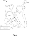
- FIG. 1 illustrates a system 100 that is configured to be implanted in a heart 101.
- the system 100 includes two or more leadless pacemakers (LPs) 102 and 104 located in different chambers of the heart.
- LP 102 is located in a right atrium, while LP 104 is located in a right ventricle.
- LPs 102 and 104 communicate with one another to inform one another of various local physiologic activities, such as local intrinsic events, local paced events and the like.
- LPs 102 and 104 may be constructed in a similar manner, but operate differently based upon which chamber LP 102 or 104 is located.
- the methods, devices and systems described herein include examples primarily in the context of LPs, it is understood that the methods, devices and systems described herein may be utilized with various other external and implanted devices.
- the methods, devices and systems may coordinate operation between various implantable medical devices (IMDs) implanted in a human, not just LPs.
- IMDs implantable medical devices
- Certain embodiments enable a first IMD to receive communications from at least a second IMD through conductive communication over at least a first channel. It should also be understood that the embodiments described herein can be used for communication between multiple IMDs, and are not limited to communication between just a first and second IMD.
- a block diagram shows an embodiment for portions of the electronics within LP 102, 104 configured to provide conductive communication through the sensing/pacing electrode.
- One or more of LPs 102 and 104 include at least two leadless electrodes 108 configured for delivering cardiac pacing pulses, sensing evoked and/or natural cardiac electrical signals, and uni-directional or bi-directional communication.
- LPs 102 and 104 may communicate over one common communication channel 105. More specifically, LPs 102 and 104 can communicate conductively over a common physical channel via the same electrodes 108 that are also used to deliver pacing pulses. Usage of the electrodes 108 for communication enables the one or more leadless cardiac pacemakers 102 and 104 to perform antenna-less and telemetry coilless communication.
- the receivers 120 and 122 can also be referred to, respectively, as a low frequency (LF) receiver 120 and a high frequency (HF) receiver 122, because the receiver 120 is configured to monitor for one or more signals within a relatively low frequency range (e.g., below 100 kHz) and the receiver 122 is configured to monitor for one or more signals within a relatively high frequency range (e.g., above 100 kHz).
- the receiver 120 (and more specifically, at least a portion thereof) is always enabled and monitoring for a wakeup notice, which can simply be a wakeup pulse, within a specific low frequency range (e.g., between 1 kHz and 100 kHz); and the receiver 122 is selectively enabled by the receiver 120.
- the high power receiver 122 is selectively enabled by the low power receiver 120, in response to the low power receiver 120 receiving a wakeup notice, so that the high power receiver 122 can receive the higher frequency signals, and thereby handle higher data throughput needed for effective i2i communications without unnecessarily and rapidly depleting the battery of the LP (which the high power receiver 122 may do if it were always enabled).
- the corresponding LP 102, 104 transmits an implant event message to the other LP 102, 104.
- the atrial LP 102 senses/paces an atrial event
- the atrial LP 102 transmits an implant event message including an event marker indicative of a nature of the event (e.g., intrinsic/sensed atrial event, paced atrial event).
- a ventricular LP 104 When a ventricular LP 104 senses/paces a ventricular event, the ventricular LP 104 transmits an implant event message including an event marker indicative of a nature of the event (e.g., intrinsic/sensed ventricular event, paced ventricular event). In certain embodiments, LP 102, 104 transmits an implant event message to the other LP 102, 104 preceding the actual pace pulse so that the remote LP can blank its sense inputs in anticipation of that remote pace pulse (to prevent inappropriate crosstalk sensing).
- an event marker indicative of a nature of the event e.g., intrinsic/sensed ventricular event, paced ventricular event.
- LP 102, 104 transmits an implant event message to the other LP 102, 104 preceding the actual pace pulse so that the remote LP can blank its sense inputs in anticipation of that remote pace pulse (to prevent inappropriate crosstalk sensing).
- each event message may include a leading trigger pulse (also referred to as an LP wakeup notice, wakeup pulse or wakeup signal) followed by an event marker.
- the notice trigger pulse (also referred to as the wakeup notice, wakeup pulse or wakeup signal) is transmitted over a first channel (e.g., with a pulse duration of approximately 10 ⁇ s to approximately 1ms and/or within a fundamental frequency range of approximately 1kHz to approximately 100kHz).
- the notice trigger pulse indicates that an event marker is about to be transmitted over a second channel (e.g., within a higher frequency range). The event marker can then be transmitted over the second channel.
- the event markers may include data indicative of one or more events (e.g., a sensed intrinsic atrial activation for an atrial located LP, a sensed intrinsic ventricular activation for a ventricular located LP).
- the event markers may include different markers for intrinsic and paced events.
- the event markers may also indicate start or end times for timers (e.g., an AV interval, a blanking interval, etc.).
- the implant event message may include a message segment that includes additional/secondary information.
- the LP that receives any implant to implant (i2i) communication from another LP (or other IMD) or from an external device may transmit a receive acknowledgement indicating that the receiving LP/IMD received the i2i communication, etc.
- LPs 102 and 104 For synchronous event signaling, LPs 102 and 104 maintain synchronization and regularly communicate at a specific interval. Synchronous event signaling allows the transmitter and receivers in each LP 102,104 to use limited (or minimal) power as each LP 102, 104 is only powered for a small fraction of the time in connection with transmission and reception. For example, LP 102, 104 may transmit/receive (Tx/Rx) communications in time slots having duration of 10-20 ⁇ s, where the Tx/Rx time slots occur periodically (e.g., every 10-20ms).
- Tx/Rx time slots having duration of 10-20 ⁇ s
- LPs 102 and 104 may lose synchronization, even in a synchronous event signaling scheme.
- features may be included in LPs 102 and 104 to maintain device synchronization, and when synchronization is lost, LPs 102 and 104 undergo operations to recover synchronization.
- synchronous event messages/signaling may introduce a delay between transmissions which causes a reaction lag at the receiving LP 102, 104. Accordingly, features may be implemented to account for the reaction lag.
- LPs 102 and 104 do not maintain communication synchronization.
- one or more of receivers 120 and 122 of LPs 102 and 104 may be "always on” (always awake) to search for incoming transmissions.
- maintaining LP receivers 120, 122 in an "always on” (always awake) state presents challenges as the received signal level often is low due to high channel attenuation caused by the patient's anatomy. Further, maintaining the receivers awake will deplete the battery 114 more quickly than may be desirable.
- the asynchronous event signaling methods avoid risks associated with losing synchronization between devices.
- the asynchronous event signaling methods utilize additional receiver current between transmissions.
- the channel attenuation may be estimated to have a gain of 1/500 to 1/10000.
- a gain factor may be 1/1000th.
- Transmit current is a design factor in addition to receiver current.
- the system may allocate one-half of the implant communication current budget to the transmitter (e.g., 0.5 ⁇ A for each transmitter).
- a transmitted voltage may be 2.5V.
- the event signal is attenuated as it propagates and would appear at LP 102, 104 receiver as an amplitude of approximately 0.25mV.
- a pulsed transmission scheme may be utilized in which communication transmissions occur correlated with an event.
- the pulsed transmission scheme may be simplified such that each transmission constitutes a single pulse of a select amplitude and width.
- LPs 102 and 104 may utilize multi-stage receivers that implement a staged receiver wakeup scheme in order to improve reliability yet remain power efficient.
- Each of LPs 102 and 104 may include first and second receivers 120 and 122 that operate with different first and second activation protocols and different first and second receive channels.
- first receiver 120 may be assigned a first activation protocol that is "always on” (also referred to as always awake) and that listens over a first receive channel that has a lower fundamental frequency range/pulse duration (e.g., 1kHz to 100kHz / 10 ⁇ s to approximately 1ms) as compared to the fundamental frequency range (e.g., greater than 100kHz / less than 10 ⁇ s per pulse) assigned to the second receive channel.
- a first activation protocol that is "always on” (also referred to as always awake) and that listens over a first receive channel that has a lower fundamental frequency range/pulse duration (e.g., 1kHz to 100kHz / 10 ⁇ s to approximately 1ms) as compared to the fundamental frequency range (e.g., greater than 100kHz / less than 10 ⁇ s per pulse) assigned to the second receive channel.
- the first receiver 120 may maintain the first channel active (awake) at all times (including when the second channel is inactive (asleep)) in order to listen for messages from a remote LP.
- the second receiver 122 may be assigned a second activation protocol that is a triggered protocol, in which the second receiver 122 becomes active (awake) in response to detection of trigger events over the first receive channel (e.g., when the incoming signal corresponds to the LP wakeup notice, activating the second channel at the local LP).
- the terms active, awake and enabled are used interchangeably herein.
- timing control circuitry may also be used for the timing of refractory periods, blanking intervals, noise detection windows, evoked response windows, alert intervals, marker channel timing, and so on.
- the processor or controller 112 can further include other dedicated circuitry and/or firmware/software components that assist in monitoring various conditions of the patient's heart and managing pacing therapies.
- the processor or controller 112 and the pulse generator 116 may be configured to transmit event messages, via the electrodes 108, in a manner that does not inadvertently capture the heart in the chamber where LP 102, 104 is located, such as when the associated chamber is not in a refractory state.
- a LP 102, 104 that receives an event message may enter an "event refractory" state (or event blanking state) following receipt of the event message.
- the event refractory/blanking state may be set to extend for a determined period of time after receipt of an event message in order to avoid the receiving LP 102, 104 from inadvertently sensing another signal as an event message that might otherwise cause retriggering.
- the receiving LP 102, 104 may detect a measurement pulse from another LP 102, 104 or programmer 109.
- LP 102, 104 may combine transmit operations with therapy.
- the transmit event marker may be configured to have similar characteristics in amplitude and pulse-width to a pacing pulse and LP 102, 104 may use the energy in the event messages to help capture the heart.
- a pacing pulse may normally be delivered with pacing parameters of 2.5V amplitude, 500 ohm impedance, 60 bpm pacing rate, 0.4 ms pulse-width.
- the foregoing pacing parameters correspond to a current draw of about 1.9 ⁇ A.
- the same LP 102, 104 may implement an event message utilizing event signaling parameters for amplitude, pulse-width, pulse rate, etc. that correspond to a current draw of approximately 0.5 ⁇ A for transmit.
- LP 102, 104 may deliver pacing pulses at relatively low amplitude.
- the power budget for event messages may be modified to be a larger portion of the overall device energy budget.
- LP 102, 104 increases an extent to which LP 102, 104 uses the event messages as part of the pacing therapy (also referred to as sharing "capture charge” and "transmit charge”).
- the nominal pacing voltage can be lowered to ⁇ 1.25 V
- a "supply halving" pacing charge circuit could reduce the battery current draw by approximately 50%.
- a 1.25V pace pulse would save 1.5 ⁇ A of pacing current budget.
- LP 102, 104 may use larger pulse-widths.
- a communication capacitor can be provided in LP 102, 104.
- the communication capacitor may be used to transmit event signals having higher voltage for the event message pulses to improve communication, such as when the LPs 102 and 104 experience difficulty sensing event messages.
- the high voltage event signaling may be used for implants with high signal attenuation or in the case of a retry for an ARQ (automatic repeat request) handshaking scheme.
- the individual LP 102 can comprise a hermetic housing 110 configured for placement on or attachment to the inside or outside of a cardiac chamber and at least two leadless electrodes 108 proximal to the housing 110 and configured for bidirectional communication with at least one other device 106 within or outside the body.
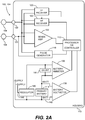
- FIG. 2A depicts a single LP 102 (or 104) and shows the LP's functional elements substantially enclosed in a hermetic housing 110.
- the LP 102 (or 104) has at least two electrodes 108 located within, on, or near the housing 110, for delivering pacing pulses to and sensing electrical activity from the muscle of the cardiac chamber, and for bidirectional communication with at least one other device within or outside the body.
- Hermetic feedthroughs 130, 131 conduct electrode signals through the housing 110.
- the housing 110 contains a primary battery 114 to supply power for pacing, sensing, and communication.
- the housing 110 also contains circuits 132 for sensing cardiac activity from the electrodes 108, receivers 120, 122 for receiving information from at least one other device via the electrodes 108, and the pulse generator 116 for generating pacing pulses for delivery via the electrodes 108 and also for transmitting information to at least one other device via the electrodes 108.
- the housing 110 can further contain circuits for monitoring device health, for example a battery current monitor 136 and a battery voltage monitor 138, and can contain circuits for controlling operations in a predetermined manner.
- an individual LP 102, 104 can be configured to deliver a pacing pulse with an event message encoded therein, with a code assigned according to pacemaker location and configured to transmit a message to one or more other leadless cardiac pacemakers via the event message coded pacing pulse.
- the pacemaker or pacemakers receiving the message are adapted to respond to the message in a predetermined manner depending on type and location of the event.
- information communicated on the incoming channel can also include an event message from another leadless cardiac pacemaker signifying that the other leadless cardiac pacemaker has sensed a heartbeat or has delivered a pacing pulse, and identifies the location of the other pacemaker.
- LP 104 may receive and relay an event message from LP 102 to the programmer.
- information communicated on the outgoing channel can also include a message to another leadless cardiac pacemaker or pacemakers, or to the ICD, that the sending leadless cardiac pacemaker has sensed a heartbeat or has delivered a pacing pulse at the location of the sending pacemaker.
- the cardiac pacing system 100 may comprise an implantable cardioverter-defibrillator (ICD) 106 in addition to leadless cardiac pacemaker 102, 104 configured for implantation in electrical contact with a cardiac chamber and for performing cardiac rhythm management functions in combination with the implantable ICD 106.
- ICD implantable cardioverter-defibrillator
- the implantable ICD 106 and the one or more leadless cardiac pacemakers 102, 104 configured for leadless intercommunication by information conduction through body tissue and/or wireless transmission between transmitters and receivers in accordance with the discussed herein.
- a cardiac pacing system 100 comprises at least one leadless cardiac pacemaker 102, 104 configured for implantation in electrical contact with a cardiac chamber and configured to perform cardiac pacing functions in combination with the co-implanted implantable cardioverter-defibrillator (ICD) 106.
- the leadless cardiac pacemaker or pacemakers 102 comprise at least two leadless electrodes 108 configured for delivering cardiac pacing pulses, sensing evoked and/or natural cardiac electrical signals, and transmitting information to the co-implanted ICD 106.
- a leadless cardiac pacemaker 102, 104 can comprise two or more leadless electrodes 108 configured for delivering cardiac pacing pulses, sensing evoked and/or natural cardiac electrical signals, and bidirectionally communicating with the co-implanted ICD 106.
- automatic identification of implanted chamber could enable the device and/or programmer to select and present the proper subset of pacing modes (e.g., AAI or VVI), and for the IPG to utilize the proper set of settings and algorithms (e.g., V-AutoCapture vs ACap-Confirm, sensing sensitivities, etc.).
- the proper subset of pacing modes e.g., AAI or VVI
- the IPG to utilize the proper set of settings and algorithms (e.g., V-AutoCapture vs ACap-Confirm, sensing sensitivities, etc.).
- the processor or controller 112 in one leadless cardiac pacemaker 102 can access signals on the electrodes 108 and can examine output pulse duration from another pacemaker for usage as a signature for determining triggering information validity and, for a signature arriving within predetermined limits, activating delivery of a pacing pulse following a predetermined delay of zero or more milliseconds.
- the predetermined delay can be preset at manufacture, programmed via an external programmer, or determined by adaptive monitoring to facilitate recognition of the triggering signal and discriminating the triggering signal from noise.
- the processor or controller 112 can examine output pulse waveform from another leadless cardiac pacemaker for usage as a signature for determining triggering information validity and, for a signature arriving within predetermined limits, activating delivery of a pacing pulse following a predetermined delay of zero or more milliseconds.
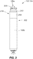
- FIG. 3 shows an LP 102, 104.
- the LP can include a hermetic housing 202 with electrodes 108a and 108b disposed thereon.
- electrode 108a can be separated from but surrounded partially by a fixation mechanism 205, and the electrode 108b can be disposed on the housing 202.
- the fixation mechanism 205 can be a fixation helix, a plurality of hooks, barbs, or other attaching features configured to attach the pacemaker to tissue, such as heart tissue.
- the electrodes 108a and 108b are examples of the electrodes 108 shown in and discussed above with reference to FIG. 2A .
- the housing can also include an electronics compartment 210 within the housing that contains the electronic components necessary for operation of the pacemaker, including, e.g., a pulse generator, receiver, a battery, and a processor for operation.
- the hermetic housing 202 can be adapted to be implanted on or in a human heart, and can be cylindrically shaped, rectangular, spherical, or any other appropriate shapes, for example.
- the housing can comprise a conductive, biocompatible, inert, and anodically safe material such as titanium, 316L stainless steel, or other similar materials.
- the housing can further comprise an insulator disposed on the conductive material to separate electrodes 108a and 108b.
- the insulator can be an insulative coating on a portion of the housing between the electrodes, and can comprise materials such as silicone, polyurethane, parylene, or another biocompatible electrical insulator commonly used for implantable medical devices.
- a single insulator 208 is disposed along the portion of the housing between electrodes 108a and 108b.
- the housing itself can comprise an insulator instead of a conductor, such as an alumina ceramic or other similar materials, and the electrodes can be disposed upon the housing.
- the electrodes 108a and 108b can comprise pace/sense electrodes, or return electrodes.
- a low-polarization coating can be applied to the electrodes, such as sintered platinum, platinum-iridium, iridium, iridium-oxide, titanium-nitride, carbon, or other materials commonly used to reduce polarization effects, for example.
- electrode 108a can be a pace/sense electrode and electrode 108b can be a return electrode.
- the electrode 108b can be a portion of the conductive housing 202 that does not include an insulator 208.
- a helical fixation mechanism 205 can enable insertion of the device endocardially or epicardially through a guiding catheter.
- a torqueable catheter can be used to rotate the housing and force the fixation device into heart tissue, thus affixing the fixation device (and also the electrode 108a in FIG. 3 ) into contact with stimulable tissue.
- Electrode 108b can serve as an indifferent electrode for sensing and pacing.
- the fixation mechanism may be coated partially or in full for electrical insulation, and a steroid-eluting matrix may be included on or near the device to minimize fibrotic reaction, as is known in conventional pacing electrode-leads.
- ventricular LP 104 shall be referred to as "vLP” and the atrial LP 102 shall be referred to as "aLP".
- LP 102, 104 that is designated as the master device may implement all or most dual-chamber diagnostic and therapy determination algorithms.
- the master device may implement all or most dual-chamber diagnostic and therapy determination algorithms.
- the vLP is a "master” device, while the aLP is a "slave” device.
- the aLP may be designated as the master device, while the vLP may be designated as the slave device.
- the master device orchestrates most or all decision-making and timing determinations (including, for example, rate-response changes).
- FIG. 4 is a timing diagram 400 demonstrating one example of an i2i communication for a paced event.
- the i2i communication may be transmitted, for example, from LP 102 to LP 104.
- an i2i transmission 402 is sent prior to delivery of a pace pulse 404 by the transmitting LP (e.g., LP 102).
- the transmitting LP e.g., LP 102
- the i2i transmission 402 includes an envelope 406 that may include one or more individual pulses.
- envelope 406 includes a low frequency pulse 408 followed by a high frequency pulse train 410.
- FIG. 5 is a timing diagram 500 demonstrating one example of an i2i communication for a sensed event.
- the i2i communication may be transmitted, for example, from LP 102 to LP 104.
- the transmitting LP e.g., LP 102
- a predetermined delay period, TdelayS after the detection, the transmitting LP transmits an i2i transmission 506 that lasts a predetermined period Ti2iS.
- the delay period may be, for example, between approximately 0.0 and 10.0 milliseconds (ms), particularly between approximately 0.1 ms and 2.0 ms, and more particularly approximately 1.0 ms.
- the first LP produces an AS/AP event marker to indicate that an atrial sensed (AS) event or atrial paced (AP) event has occurred or will occur in the immediate future.
- AS atrial sensed
- AP atrial paced
- the AS and AP event markers may be transmitted following the corresponding AS or AP event.
- the first LP may transmit the AP event marker slightly prior to delivering an atrial pacing pulse.
- the first and second LPs may operate in a "pure" master/slave relation, where the master LP delivers "command" markers in addition to or in place of "event” markers.
- a command marker directs the slave LP to perform an action such as to deliver a pacing pulse and the like.
- the slave LP delivers an immediate pacing pulse to the atrium when receiving an AP command marker from the master LP.
- an aLP when an aLP transmits an event message that includes an AS event marker (indicating that the aLP sensed an intrinsic atrial event), the vLP initiates an AV interval timer. If the aLP transmits an AS event marker for all sensed events, then the vLP would preferably first determine that a PVAB or PVARP interval is not active before initiating an AV interval timer. If however the aLP transmits an AS event marker only when an intrinsic signal is sensed outside of a PVAB or PVARP interval, then the vLP could initiate the AV interval timer upon receiving an AS event marker without first checking the PVAB or PVARP status.
- the foregoing event markers are examples of a subset of markers that may be used to enable the aLP and vLP to maintain full dual chamber functionality.
- the vLP may perform all dual-chamber algorithms, while the aLP may perform atrial-based hardware-related functions, such as PVAB, implemented locally within the aLP.
- the aLP is effectively treated as a remote 'wireless' atrial pace/sense electrode.
- the vLP may perform most but not all dual-chamber algorithms, while the aLP may perform a subset of diagnostic and therapeutic algorithms.
- vLP and aLP may equally perform diagnostic and therapeutic algorithms.
- decision responsibilities may be partitioned separately to one of the aLP or vLP. In other embodiments, decision responsibilities may involve joint inputs and responsibilities.
- the wakeup signal that the receiver 120 is configured to monitor for and detect for has a low amplitude that may be under 1mV. Accordingly, it would not be useful to implement the receiver 120 using a traditional differential amplifier because the input offset voltage of a traditional differential amplifier will typically be greater than 1mV (e.g., likely 10mV or more with additional variation over time and temperature). Additionally, a traditional differential amplifier is very susceptible to input offset voltage drift, which is undesirable when attempting to detect low amplitude signals of 1mV or less.
- the receiver 120 is shown as including two differential amplifiers 124a and 124b, each of which includes differential inputs and an output.
- the differential amplifiers 124a and 124b can be referred to collectively as the differential amplifiers 124, or individually as a differential amplifier 124.
- Each of the differential amplifiers 124 includes a respective enable terminal that allows each of the differential amplifiers 124 to be selectively enabled.
- Each of the differential amplifiers 124 while enabled, drains current (e.g., ⁇ 300nA) and thereby power from the battery.
- each of the differential amplifiers 124 can be referred to as an amplified difference signal.
- each of the differential amplifiers 124 can be configured to nominally output a LOW amplified difference signal (when the wakeup pulse is not detected) and output a HIGH amplified difference signal in response to the wakeup pulse being detected.
- each of the differential amplifiers 124 can be configured nominally output a HIGH amplified difference signal (when the wakeup pulse is not detected) and output a LOW amplified difference signal in response to the wakeup pulse being detected.
- the outputs of the differential amplifiers 124a and 124b are shown as being provided to respective inputs of an OR gate circuit 126, which is used to combine the outputs of the differential amplifiers 124a and 124b. More specifically, the output of the OR gate circuit 126 will go HIGH in response to at least one of the inputs to the OR gate circuit 126 going HIGH. One of the inputs to the OR gate circuit 126 will be HIGH when one of the differential amplifiers 124a and 124b detects the wakeup signal (e.g., the wakeup pulse) that the differential amplifiers 124a and 124b are each monitoring for.
- the wakeup signal e.g., the wakeup pulse
- the pulse conditioning circuit 128 can be configured to output a pulse of a specific amplitude and pulse-width in response to the input of the pulse conditioning circuit 128 going from LOW to HIGH and remaining HIGH for at least a predetermined period of time.
- Other variations are also possible, and within the scope of the embodiments of the present technology. More generally, other ways of combining the outputs of the differential amplifiers 124a and 124b into one signal, besides using the OR gate circuit 126, are possible and are within the scope of the embodiments of the present technology described herein.
- step 602 involves selectively enabling the first and second differential amplifiers such that at any given time at least one of the first and second differential amplifiers is enabled.
- step 602 is performed such that the first and second differential amplifiers are simultaneously enabled for less than 20% of a time that only one of the first and second differential amplifiers is enabled.
Landscapes
- Health & Medical Sciences (AREA)
- Engineering & Computer Science (AREA)
- Life Sciences & Earth Sciences (AREA)
- Biomedical Technology (AREA)
- Nuclear Medicine, Radiotherapy & Molecular Imaging (AREA)
- Radiology & Medical Imaging (AREA)
- Animal Behavior & Ethology (AREA)
- General Health & Medical Sciences (AREA)
- Public Health (AREA)
- Veterinary Medicine (AREA)
- Heart & Thoracic Surgery (AREA)
- Cardiology (AREA)
- Physics & Mathematics (AREA)
- Power Engineering (AREA)
- Biophysics (AREA)
- Computer Networks & Wireless Communication (AREA)
- Signal Processing (AREA)
- Acoustics & Sound (AREA)
- Electromagnetism (AREA)
- Vascular Medicine (AREA)
- Physiology (AREA)
- Electrotherapy Devices (AREA)
Applications Claiming Priority (2)
| Application Number | Priority Date | Filing Date | Title |
|---|---|---|---|
| US15/605,756 US10722724B2 (en) | 2017-05-25 | 2017-05-25 | Always on receiver with offset correction for implant to implant communication in an implantable medical system |
| PCT/US2018/028392 WO2018217340A1 (en) | 2017-05-25 | 2018-04-19 | Always on receiver with offset correction for implant to implant communication in an implantable medical system |
Publications (2)
| Publication Number | Publication Date |
|---|---|
| EP3630276A1 EP3630276A1 (en) | 2020-04-08 |
| EP3630276B1 true EP3630276B1 (en) | 2021-10-20 |
Family
ID=62117032
Family Applications (1)
| Application Number | Title | Priority Date | Filing Date |
|---|---|---|---|
| EP18723186.5A Active EP3630276B1 (en) | 2017-05-25 | 2018-04-19 | Always on receiver with offset correction for implant to implant communication in an implantable medical system |
Country Status (5)
| Country | Link |
|---|---|
| US (2) | US10722724B2 (enExample) |
| EP (1) | EP3630276B1 (enExample) |
| JP (1) | JP7026141B2 (enExample) |
| CN (1) | CN110536718B (enExample) |
| WO (1) | WO2018217340A1 (enExample) |
Families Citing this family (28)
| Publication number | Priority date | Publication date | Assignee | Title |
|---|---|---|---|---|
| US10758737B2 (en) | 2016-09-21 | 2020-09-01 | Cardiac Pacemakers, Inc. | Using sensor data from an intracardially implanted medical device to influence operation of an extracardially implantable cardioverter |
| WO2018057626A1 (en) | 2016-09-21 | 2018-03-29 | Cardiac Pacemakers, Inc. | Implantable cardiac monitor |
| WO2018081017A1 (en) | 2016-10-27 | 2018-05-03 | Cardiac Pacemakers, Inc. | Implantable medical device with pressure sensor |
| US10413733B2 (en) | 2016-10-27 | 2019-09-17 | Cardiac Pacemakers, Inc. | Implantable medical device with gyroscope |
| WO2018081133A1 (en) | 2016-10-27 | 2018-05-03 | Cardiac Pacemakers, Inc. | Implantable medical device having a sense channel with performance adjustment |
| US10737102B2 (en) | 2017-01-26 | 2020-08-11 | Cardiac Pacemakers, Inc. | Leadless implantable device with detachable fixation |
| US10905872B2 (en) | 2017-04-03 | 2021-02-02 | Cardiac Pacemakers, Inc. | Implantable medical device with a movable electrode biased toward an extended position |
| US10821288B2 (en) | 2017-04-03 | 2020-11-03 | Cardiac Pacemakers, Inc. | Cardiac pacemaker with pacing pulse energy adjustment based on sensed heart rate |
| US10722724B2 (en) | 2017-05-25 | 2020-07-28 | Pacesetter, Inc. | Always on receiver with offset correction for implant to implant communication in an implantable medical system |
| EP3668592B1 (en) | 2017-08-18 | 2021-11-17 | Cardiac Pacemakers, Inc. | Implantable medical device with pressure sensor |
| WO2019036568A1 (en) | 2017-08-18 | 2019-02-21 | Cardiac Pacemakers, Inc. | IMPLANTABLE MEDICAL DEVICE COMPRISING A FLOW CONCENTRATOR AND A RECEPTION COIL PROVIDED AROUND THE FLOW CONCENTRATOR |
| US11235163B2 (en) | 2017-09-20 | 2022-02-01 | Cardiac Pacemakers, Inc. | Implantable medical device with multiple modes of operation |
| US11185703B2 (en) | 2017-11-07 | 2021-11-30 | Cardiac Pacemakers, Inc. | Leadless cardiac pacemaker for bundle of his pacing |
| CN111432874A (zh) | 2017-12-01 | 2020-07-17 | 心脏起搏器股份公司 | 从心室植入的无引线心脏起搏器检测搜索窗口内心房收缩定时基准的方法和系统 |
| CN111417432B (zh) | 2017-12-01 | 2024-04-30 | 心脏起搏器股份公司 | 具有复归行为的无引线心脏起搏器 |
| EP3717063B1 (en) | 2017-12-01 | 2023-12-27 | Cardiac Pacemakers, Inc. | Systems for detecting atrial contraction timing fiducials and determining a cardiac interval from a ventricularly implanted leadless cardiac pacemaker |
| CN111417433B (zh) | 2017-12-01 | 2024-04-30 | 心脏起搏器股份公司 | 从心室植入的无引线心脏起搏器检测心室充盈期间心房收缩定时基准的方法和系统 |
| US11529523B2 (en) | 2018-01-04 | 2022-12-20 | Cardiac Pacemakers, Inc. | Handheld bridge device for providing a communication bridge between an implanted medical device and a smartphone |
| CN111556773A (zh) | 2018-01-04 | 2020-08-18 | 心脏起搏器股份公司 | 无逐搏通信的双腔起搏 |
| US11297569B2 (en) * | 2018-10-05 | 2022-04-05 | Qualcomm Incorporated | Wakeup signaling resource occasions |
| WO2020205401A1 (en) * | 2019-03-29 | 2020-10-08 | Cardiac Pacemakers, Inc. | Systems and methods for treating cardiac arrhythmias |
| EP3946556B1 (en) | 2019-03-29 | 2024-06-19 | Cardiac Pacemakers, Inc. | Systems for treating cardiac arrhythmias |
| EP3721789B1 (en) * | 2019-04-12 | 2023-07-26 | BIOTRONIK SE & Co. KG | Intra-cardiac communications to provide direct timing information without electrical interferences |
| WO2021050679A1 (en) | 2019-09-11 | 2021-03-18 | Cardiac Pacemakers, Inc. | Tools and systems for implanting and/or retrieving a leadless cardiac pacing device with helix fixation |
| WO2021050685A1 (en) | 2019-09-11 | 2021-03-18 | Cardiac Pacemakers, Inc. | Tools and systems for implanting and/or retrieving a leadless cardiac pacing device with helix fixation |
| US11722108B2 (en) | 2021-11-30 | 2023-08-08 | Pacesetter, Inc. | Fully-differential preamplifier |
| US12113649B2 (en) * | 2021-11-30 | 2024-10-08 | Pacesetter, Inc. | Fully-differential receiver for receiving conducted communication signals |
| CN114587374B (zh) * | 2022-03-18 | 2024-09-03 | 苏州无双医疗设备有限公司 | 一种植入式医疗设备及前端电路 |
Family Cites Families (16)
| Publication number | Priority date | Publication date | Assignee | Title |
|---|---|---|---|---|
| US4390020A (en) * | 1983-02-17 | 1983-06-28 | Medtronic, Inc. | Implantable medical device and power source depletion control therefor |
| SE9201602D0 (sv) * | 1992-05-21 | 1992-05-21 | Siemens Elema Ab | Anordning foer att minska stroemfoerbrukningen hos medicinsk, i maenniskokroppen implanterbar, elektrisk utrustning |
| US5713934A (en) | 1995-10-12 | 1998-02-03 | Pacesetter, Inc. | Evoked and spontaneous cardiac activity detection in a dual-chamber electronic pacemaker and method |
| US9623208B2 (en) | 2004-01-12 | 2017-04-18 | Varian Medical Systems, Inc. | Instruments with location markers and methods for tracking instruments through anatomical passageways |
| US9168383B2 (en) * | 2005-10-14 | 2015-10-27 | Pacesetter, Inc. | Leadless cardiac pacemaker with conducted communication |
| EP2496936B1 (en) | 2009-10-16 | 2018-02-21 | Microchips Biotech, Inc. | Multi-channel potentiostat for biosensor arrays and method of operation |
| WO2012101467A1 (en) | 2011-01-24 | 2012-08-02 | Tredefin S.A. | Efficient low noise differential amplifier, reutilizing the bias current |
| CN102901902A (zh) * | 2011-07-28 | 2013-01-30 | 飞思卡尔半导体公司 | 半导体器件的并联电源连接的测试方法 |
| US8805502B2 (en) * | 2011-12-27 | 2014-08-12 | Cardiac Pacemakers, Inc. | Managing cross therapy delivery in a multiple therapy implantable device |
| KR20150069936A (ko) * | 2013-12-16 | 2015-06-24 | 현대자동차주식회사 | 차동 증폭기의 오프셋 보정장치 및 방법 |
| US9692473B2 (en) * | 2014-05-16 | 2017-06-27 | Analog Devices, Inc. | Offset compensation in a receiver |
| US9561382B2 (en) * | 2014-11-03 | 2017-02-07 | Pacesetter, Inc. | System and method for low power communication between implantable devices |
| US9614481B2 (en) * | 2015-03-31 | 2017-04-04 | Analog Devices, Inc. | Apparatus and methods for chopping ripple reduction in amplifiers |
| KR102432873B1 (ko) * | 2016-02-05 | 2022-08-17 | 에스케이하이닉스 주식회사 | 리시버 회로 및 이를 이용하는 시스템 |
| CN105979655A (zh) * | 2016-06-22 | 2016-09-28 | 成都飞凯瑞科技有限公司 | 一种基于低通滤波电路的光控led用信号处理系统 |
| US10722724B2 (en) | 2017-05-25 | 2020-07-28 | Pacesetter, Inc. | Always on receiver with offset correction for implant to implant communication in an implantable medical system |
-
2017
- 2017-05-25 US US15/605,756 patent/US10722724B2/en active Active
-
2018
- 2018-04-19 EP EP18723186.5A patent/EP3630276B1/en active Active
- 2018-04-19 JP JP2019564081A patent/JP7026141B2/ja active Active
- 2018-04-19 WO PCT/US2018/028392 patent/WO2018217340A1/en not_active Ceased
- 2018-04-19 CN CN201880025389.1A patent/CN110536718B/zh active Active
-
2019
- 2019-11-14 US US16/684,270 patent/US11207534B2/en active Active
Also Published As
| Publication number | Publication date |
|---|---|
| US10722724B2 (en) | 2020-07-28 |
| JP2020520715A (ja) | 2020-07-16 |
| US11207534B2 (en) | 2021-12-28 |
| WO2018217340A1 (en) | 2018-11-29 |
| US20180339160A1 (en) | 2018-11-29 |
| EP3630276A1 (en) | 2020-04-08 |
| JP7026141B2 (ja) | 2022-02-25 |
| CN110536718A (zh) | 2019-12-03 |
| US20200078595A1 (en) | 2020-03-12 |
| CN110536718B (zh) | 2021-05-11 |
Similar Documents
| Publication | Publication Date | Title |
|---|---|---|
| EP3630276B1 (en) | Always on receiver with offset correction for implant to implant communication in an implantable medical system | |
| US11206981B2 (en) | Mitigating excessive wakeups in leadless dual-chamber pacing systems and other IMD systems | |
| US11239928B2 (en) | Dynamic sensitivity and strength control of communication signals between implantable medical devices | |
| EP3906092B1 (en) | Terminating pacemaker mediated tachycardia (pmt) in dual chamber leadless pacemaker system | |
| EP4091663B1 (en) | Improved implant-to-implant communication for use with implantable medical devices | |
| US12151112B2 (en) | Mitigating false messages and effects thereof in multi-chamber leadless pacemaker systems and other IMD systems | |
| US11766570B2 (en) | Managing communication interference in leadless dual-chamber pacing systems and other IMD systems | |
| EP4534138A1 (en) | Dual chamber leadless pacemaker systems and methods for use therewith | |
| EP4487902B1 (en) | Systems for reducing communication burden between leadless pacemakers | |
| EP4663236A1 (en) | Improved implant to implant communication for use with implantable medical devices | |
| US20240350812A1 (en) | Implant to implant communication for use with implantable medical devices |
Legal Events
| Date | Code | Title | Description |
|---|---|---|---|
| STAA | Information on the status of an ep patent application or granted ep patent |
Free format text: STATUS: UNKNOWN |
|
| STAA | Information on the status of an ep patent application or granted ep patent |
Free format text: STATUS: THE INTERNATIONAL PUBLICATION HAS BEEN MADE |
|
| PUAI | Public reference made under article 153(3) epc to a published international application that has entered the european phase |
Free format text: ORIGINAL CODE: 0009012 |
|
| STAA | Information on the status of an ep patent application or granted ep patent |
Free format text: STATUS: REQUEST FOR EXAMINATION WAS MADE |
|
| 17P | Request for examination filed |
Effective date: 20200102 |
|
| AK | Designated contracting states |
Kind code of ref document: A1 Designated state(s): AL AT BE BG CH CY CZ DE DK EE ES FI FR GB GR HR HU IE IS IT LI LT LU LV MC MK MT NL NO PL PT RO RS SE SI SK SM TR |
|
| AX | Request for extension of the european patent |
Extension state: BA ME |
|
| RIN1 | Information on inventor provided before grant (corrected) |
Inventor name: CARROLL, KENNETH J. |
|
| DAV | Request for validation of the european patent (deleted) | ||
| DAX | Request for extension of the european patent (deleted) | ||
| STAA | Information on the status of an ep patent application or granted ep patent |
Free format text: STATUS: EXAMINATION IS IN PROGRESS |
|
| 17Q | First examination report despatched |
Effective date: 20210128 |
|
| GRAP | Despatch of communication of intention to grant a patent |
Free format text: ORIGINAL CODE: EPIDOSNIGR1 |
|
| STAA | Information on the status of an ep patent application or granted ep patent |
Free format text: STATUS: GRANT OF PATENT IS INTENDED |
|
| INTG | Intention to grant announced |
Effective date: 20210615 |
|
| GRAS | Grant fee paid |
Free format text: ORIGINAL CODE: EPIDOSNIGR3 |
|
| GRAA | (expected) grant |
Free format text: ORIGINAL CODE: 0009210 |
|
| STAA | Information on the status of an ep patent application or granted ep patent |
Free format text: STATUS: THE PATENT HAS BEEN GRANTED |
|
| AK | Designated contracting states |
Kind code of ref document: B1 Designated state(s): AL AT BE BG CH CY CZ DE DK EE ES FI FR GB GR HR HU IE IS IT LI LT LU LV MC MK MT NL NO PL PT RO RS SE SI SK SM TR |
|
| REG | Reference to a national code |
Ref country code: GB Ref legal event code: FG4D |
|
| REG | Reference to a national code |
Ref country code: CH Ref legal event code: EP |
|
| REG | Reference to a national code |
Ref country code: DE Ref legal event code: R096 Ref document number: 602018025309 Country of ref document: DE |
|
| REG | Reference to a national code |
Ref country code: IE Ref legal event code: FG4D |
|
| REG | Reference to a national code |
Ref country code: AT Ref legal event code: REF Ref document number: 1439426 Country of ref document: AT Kind code of ref document: T Effective date: 20211115 |
|
| REG | Reference to a national code |
Ref country code: LT Ref legal event code: MG9D |
|
| REG | Reference to a national code |
Ref country code: NL Ref legal event code: MP Effective date: 20211020 |
|
| REG | Reference to a national code |
Ref country code: AT Ref legal event code: MK05 Ref document number: 1439426 Country of ref document: AT Kind code of ref document: T Effective date: 20211020 |
|
| PG25 | Lapsed in a contracting state [announced via postgrant information from national office to epo] |
Ref country code: RS Free format text: LAPSE BECAUSE OF FAILURE TO SUBMIT A TRANSLATION OF THE DESCRIPTION OR TO PAY THE FEE WITHIN THE PRESCRIBED TIME-LIMIT Effective date: 20211020 Ref country code: LT Free format text: LAPSE BECAUSE OF FAILURE TO SUBMIT A TRANSLATION OF THE DESCRIPTION OR TO PAY THE FEE WITHIN THE PRESCRIBED TIME-LIMIT Effective date: 20211020 Ref country code: FI Free format text: LAPSE BECAUSE OF FAILURE TO SUBMIT A TRANSLATION OF THE DESCRIPTION OR TO PAY THE FEE WITHIN THE PRESCRIBED TIME-LIMIT Effective date: 20211020 Ref country code: BG Free format text: LAPSE BECAUSE OF FAILURE TO SUBMIT A TRANSLATION OF THE DESCRIPTION OR TO PAY THE FEE WITHIN THE PRESCRIBED TIME-LIMIT Effective date: 20220120 Ref country code: AT Free format text: LAPSE BECAUSE OF FAILURE TO SUBMIT A TRANSLATION OF THE DESCRIPTION OR TO PAY THE FEE WITHIN THE PRESCRIBED TIME-LIMIT Effective date: 20211020 |
|
| PG25 | Lapsed in a contracting state [announced via postgrant information from national office to epo] |
Ref country code: IS Free format text: LAPSE BECAUSE OF FAILURE TO SUBMIT A TRANSLATION OF THE DESCRIPTION OR TO PAY THE FEE WITHIN THE PRESCRIBED TIME-LIMIT Effective date: 20220220 Ref country code: SE Free format text: LAPSE BECAUSE OF FAILURE TO SUBMIT A TRANSLATION OF THE DESCRIPTION OR TO PAY THE FEE WITHIN THE PRESCRIBED TIME-LIMIT Effective date: 20211020 Ref country code: PT Free format text: LAPSE BECAUSE OF FAILURE TO SUBMIT A TRANSLATION OF THE DESCRIPTION OR TO PAY THE FEE WITHIN THE PRESCRIBED TIME-LIMIT Effective date: 20220221 Ref country code: PL Free format text: LAPSE BECAUSE OF FAILURE TO SUBMIT A TRANSLATION OF THE DESCRIPTION OR TO PAY THE FEE WITHIN THE PRESCRIBED TIME-LIMIT Effective date: 20211020 Ref country code: NO Free format text: LAPSE BECAUSE OF FAILURE TO SUBMIT A TRANSLATION OF THE DESCRIPTION OR TO PAY THE FEE WITHIN THE PRESCRIBED TIME-LIMIT Effective date: 20220120 Ref country code: NL Free format text: LAPSE BECAUSE OF FAILURE TO SUBMIT A TRANSLATION OF THE DESCRIPTION OR TO PAY THE FEE WITHIN THE PRESCRIBED TIME-LIMIT Effective date: 20211020 Ref country code: LV Free format text: LAPSE BECAUSE OF FAILURE TO SUBMIT A TRANSLATION OF THE DESCRIPTION OR TO PAY THE FEE WITHIN THE PRESCRIBED TIME-LIMIT Effective date: 20211020 Ref country code: HR Free format text: LAPSE BECAUSE OF FAILURE TO SUBMIT A TRANSLATION OF THE DESCRIPTION OR TO PAY THE FEE WITHIN THE PRESCRIBED TIME-LIMIT Effective date: 20211020 Ref country code: GR Free format text: LAPSE BECAUSE OF FAILURE TO SUBMIT A TRANSLATION OF THE DESCRIPTION OR TO PAY THE FEE WITHIN THE PRESCRIBED TIME-LIMIT Effective date: 20220121 Ref country code: ES Free format text: LAPSE BECAUSE OF FAILURE TO SUBMIT A TRANSLATION OF THE DESCRIPTION OR TO PAY THE FEE WITHIN THE PRESCRIBED TIME-LIMIT Effective date: 20211020 |
|
| REG | Reference to a national code |
Ref country code: DE Ref legal event code: R097 Ref document number: 602018025309 Country of ref document: DE |
|
| PG25 | Lapsed in a contracting state [announced via postgrant information from national office to epo] |
Ref country code: SM Free format text: LAPSE BECAUSE OF FAILURE TO SUBMIT A TRANSLATION OF THE DESCRIPTION OR TO PAY THE FEE WITHIN THE PRESCRIBED TIME-LIMIT Effective date: 20211020 Ref country code: SK Free format text: LAPSE BECAUSE OF FAILURE TO SUBMIT A TRANSLATION OF THE DESCRIPTION OR TO PAY THE FEE WITHIN THE PRESCRIBED TIME-LIMIT Effective date: 20211020 Ref country code: RO Free format text: LAPSE BECAUSE OF FAILURE TO SUBMIT A TRANSLATION OF THE DESCRIPTION OR TO PAY THE FEE WITHIN THE PRESCRIBED TIME-LIMIT Effective date: 20211020 Ref country code: EE Free format text: LAPSE BECAUSE OF FAILURE TO SUBMIT A TRANSLATION OF THE DESCRIPTION OR TO PAY THE FEE WITHIN THE PRESCRIBED TIME-LIMIT Effective date: 20211020 Ref country code: DK Free format text: LAPSE BECAUSE OF FAILURE TO SUBMIT A TRANSLATION OF THE DESCRIPTION OR TO PAY THE FEE WITHIN THE PRESCRIBED TIME-LIMIT Effective date: 20211020 Ref country code: CZ Free format text: LAPSE BECAUSE OF FAILURE TO SUBMIT A TRANSLATION OF THE DESCRIPTION OR TO PAY THE FEE WITHIN THE PRESCRIBED TIME-LIMIT Effective date: 20211020 |
|
| PLBE | No opposition filed within time limit |
Free format text: ORIGINAL CODE: 0009261 |
|
| STAA | Information on the status of an ep patent application or granted ep patent |
Free format text: STATUS: NO OPPOSITION FILED WITHIN TIME LIMIT |
|
| 26N | No opposition filed |
Effective date: 20220721 |
|
| PG25 | Lapsed in a contracting state [announced via postgrant information from national office to epo] |
Ref country code: AL Free format text: LAPSE BECAUSE OF FAILURE TO SUBMIT A TRANSLATION OF THE DESCRIPTION OR TO PAY THE FEE WITHIN THE PRESCRIBED TIME-LIMIT Effective date: 20211020 |
|
| PG25 | Lapsed in a contracting state [announced via postgrant information from national office to epo] |
Ref country code: SI Free format text: LAPSE BECAUSE OF FAILURE TO SUBMIT A TRANSLATION OF THE DESCRIPTION OR TO PAY THE FEE WITHIN THE PRESCRIBED TIME-LIMIT Effective date: 20211020 |
|
| GBPC | Gb: european patent ceased through non-payment of renewal fee |
Effective date: 20220419 |
|
| REG | Reference to a national code |
Ref country code: BE Ref legal event code: MM Effective date: 20220430 |
|
| PG25 | Lapsed in a contracting state [announced via postgrant information from national office to epo] |
Ref country code: MC Free format text: LAPSE BECAUSE OF FAILURE TO SUBMIT A TRANSLATION OF THE DESCRIPTION OR TO PAY THE FEE WITHIN THE PRESCRIBED TIME-LIMIT Effective date: 20211020 Ref country code: LU Free format text: LAPSE BECAUSE OF NON-PAYMENT OF DUE FEES Effective date: 20220419 Ref country code: GB Free format text: LAPSE BECAUSE OF NON-PAYMENT OF DUE FEES Effective date: 20220419 |
|
| PG25 | Lapsed in a contracting state [announced via postgrant information from national office to epo] |
Ref country code: BE Free format text: LAPSE BECAUSE OF NON-PAYMENT OF DUE FEES Effective date: 20220430 |
|
| PG25 | Lapsed in a contracting state [announced via postgrant information from national office to epo] |
Ref country code: IE Free format text: LAPSE BECAUSE OF NON-PAYMENT OF DUE FEES Effective date: 20220419 |
|
| P01 | Opt-out of the competence of the unified patent court (upc) registered |
Effective date: 20230616 |
|
| PG25 | Lapsed in a contracting state [announced via postgrant information from national office to epo] |
Ref country code: MK Free format text: LAPSE BECAUSE OF FAILURE TO SUBMIT A TRANSLATION OF THE DESCRIPTION OR TO PAY THE FEE WITHIN THE PRESCRIBED TIME-LIMIT Effective date: 20211020 Ref country code: CY Free format text: LAPSE BECAUSE OF FAILURE TO SUBMIT A TRANSLATION OF THE DESCRIPTION OR TO PAY THE FEE WITHIN THE PRESCRIBED TIME-LIMIT Effective date: 20211020 |
|
| PG25 | Lapsed in a contracting state [announced via postgrant information from national office to epo] |
Ref country code: HU Free format text: LAPSE BECAUSE OF FAILURE TO SUBMIT A TRANSLATION OF THE DESCRIPTION OR TO PAY THE FEE WITHIN THE PRESCRIBED TIME-LIMIT; INVALID AB INITIO Effective date: 20180419 |
|
| PG25 | Lapsed in a contracting state [announced via postgrant information from national office to epo] |
Ref country code: MT Free format text: LAPSE BECAUSE OF FAILURE TO SUBMIT A TRANSLATION OF THE DESCRIPTION OR TO PAY THE FEE WITHIN THE PRESCRIBED TIME-LIMIT Effective date: 20211020 |
|
| PGFP | Annual fee paid to national office [announced via postgrant information from national office to epo] |
Ref country code: FR Payment date: 20250319 Year of fee payment: 8 |
|
| PGFP | Annual fee paid to national office [announced via postgrant information from national office to epo] |
Ref country code: DE Payment date: 20250317 Year of fee payment: 8 |
|
| PGFP | Annual fee paid to national office [announced via postgrant information from national office to epo] |
Ref country code: IT Payment date: 20250410 Year of fee payment: 8 |
|
| PGFP | Annual fee paid to national office [announced via postgrant information from national office to epo] |
Ref country code: CH Payment date: 20250501 Year of fee payment: 8 |