EP3629960B1 - Orthopädische befestigungselemente mit variablem winkel zur fixierung eines orthopädischen implantats - Google Patents
Orthopädische befestigungselemente mit variablem winkel zur fixierung eines orthopädischen implantats Download PDFInfo
- Publication number
- EP3629960B1 EP3629960B1 EP18804963.9A EP18804963A EP3629960B1 EP 3629960 B1 EP3629960 B1 EP 3629960B1 EP 18804963 A EP18804963 A EP 18804963A EP 3629960 B1 EP3629960 B1 EP 3629960B1
- Authority
- EP
- European Patent Office
- Prior art keywords
- pivot member
- fastener
- aperture
- plate
- relative
- Prior art date
- Legal status (The legal status is an assumption and is not a legal conclusion. Google has not performed a legal analysis and makes no representation as to the accuracy of the status listed.)
- Active
Links
Images


Classifications
-
- A—HUMAN NECESSITIES
- A61—MEDICAL OR VETERINARY SCIENCE; HYGIENE
- A61B—DIAGNOSIS; SURGERY; IDENTIFICATION
- A61B17/00—Surgical instruments, devices or methods
- A61B17/56—Surgical instruments or methods for treatment of bones or joints; Devices specially adapted therefor
- A61B17/58—Surgical instruments or methods for treatment of bones or joints; Devices specially adapted therefor for osteosynthesis, e.g. bone plates, screws or setting implements
- A61B17/68—Internal fixation devices, including fasteners and spinal fixators, even if a part thereof projects from the skin
- A61B17/80—Cortical plates, i.e. bone plates; Instruments for holding or positioning cortical plates, or for compressing bones attached to cortical plates
- A61B17/8033—Cortical plates, i.e. bone plates; Instruments for holding or positioning cortical plates, or for compressing bones attached to cortical plates having indirect contact with screw heads, or having contact with screw heads maintained with the aid of additional components, e.g. nuts, wedges or head covers
- A61B17/8047—Cortical plates, i.e. bone plates; Instruments for holding or positioning cortical plates, or for compressing bones attached to cortical plates having indirect contact with screw heads, or having contact with screw heads maintained with the aid of additional components, e.g. nuts, wedges or head covers wherein the additional element surrounds the screw head in the plate hole
-
- A—HUMAN NECESSITIES
- A61—MEDICAL OR VETERINARY SCIENCE; HYGIENE
- A61B—DIAGNOSIS; SURGERY; IDENTIFICATION
- A61B17/00—Surgical instruments, devices or methods
- A61B17/56—Surgical instruments or methods for treatment of bones or joints; Devices specially adapted therefor
- A61B17/58—Surgical instruments or methods for treatment of bones or joints; Devices specially adapted therefor for osteosynthesis, e.g. bone plates, screws or setting implements
- A61B17/68—Internal fixation devices, including fasteners and spinal fixators, even if a part thereof projects from the skin
- A61B17/84—Fasteners therefor or fasteners being internal fixation devices
- A61B17/86—Pins or screws or threaded wires; nuts therefor
- A61B17/8605—Heads, i.e. proximal ends projecting from bone
-
- A—HUMAN NECESSITIES
- A61—MEDICAL OR VETERINARY SCIENCE; HYGIENE
- A61B—DIAGNOSIS; SURGERY; IDENTIFICATION
- A61B17/00—Surgical instruments, devices or methods
- A61B17/56—Surgical instruments or methods for treatment of bones or joints; Devices specially adapted therefor
- A61B17/58—Surgical instruments or methods for treatment of bones or joints; Devices specially adapted therefor for osteosynthesis, e.g. bone plates, screws or setting implements
- A61B17/68—Internal fixation devices, including fasteners and spinal fixators, even if a part thereof projects from the skin
- A61B17/84—Fasteners therefor or fasteners being internal fixation devices
- A61B17/86—Pins or screws or threaded wires; nuts therefor
- A61B17/8685—Pins or screws or threaded wires; nuts therefor comprising multiple separate parts
-
- A—HUMAN NECESSITIES
- A61—MEDICAL OR VETERINARY SCIENCE; HYGIENE
- A61B—DIAGNOSIS; SURGERY; IDENTIFICATION
- A61B17/00—Surgical instruments, devices or methods
- A61B17/56—Surgical instruments or methods for treatment of bones or joints; Devices specially adapted therefor
- A61B17/58—Surgical instruments or methods for treatment of bones or joints; Devices specially adapted therefor for osteosynthesis, e.g. bone plates, screws or setting implements
- A61B17/88—Osteosynthesis instruments; Methods or means for implanting or extracting internal or external fixation devices
- A61B17/8875—Screwdrivers, spanners or wrenches
- A61B17/8877—Screwdrivers, spanners or wrenches characterised by the cross-section of the driver bit
Definitions
- the present disclosure generally relates to orthopedic hardware, and in particular to plates and screws for fixation of orthopedic hardware relative to the bone of a patient.
- orthopedic plates may be used for fixation of bones that have been fractured.
- a variety of plate types may be provided for use in different contexts.
- a plate type may be particular to a given anatomical use and/or plate function.
- most often such plates are affixed to the bone of a patient using surgical fasteners such as bone screws.
- Some proposed systems include multiple, separately provided pieces that must be manipulated and arranged by the surgeon prior to or at the time of screw insertion.
- the surgeon is required to manipulate a number of parts in relation to screw insertion, which may be particularly difficult when screw insertion is provided in awkward positions relative to the anatomy of the patient.
- the potential for loss of one or more of these parts exists, which may increase foreign body exposure in the surgical site.
- the plate through which the screw passes during insertion may comprise a relatively softer material than the screw.
- the screw head is provided with threads that cut into the plate to tap threads as the screw is advanced relative to the plate, thus locking the screw to the plate. That is, the screw may provide self-tapping of the relatively softer material to engage the plate to lock the screw to the plate.
- the potential for metal shavings to be produced as the screw head self-taps to the plate. While efforts may be undertaken to remove such metal shavings, any remaining shavings may remain that may result in soft tissue damage.
- this approach may result in cold fusion to occur between the screw head and the plate.
- the screw when removing the plate, it may be necessary to use alternative techniques for screw removal other than simply unscrewing the screw from the plate and bone. For instance, the screw may be required to be drilled to remove the screw from the plate and a complicated screw removal process may be undertaken.
- embodiments described herein facilitate locking a fastener to a plate such that the fastener may be positioned in different relative angles relative to the plate.
- a pivot member is provided that facilitates locking interaction between a fastener and a plate.
- the present disclosure contemplates an efficient, easy to use system in which components are secured so as to provide a traditional workflow during surgery. That is, the pivot member is restrainedly engaged with the plate such that a surgeon need not separately manipulate a third component beyond the plate and fastener.
- the fastener when a fastener has been used for fixation of a plate to a bone, the fastener is locked to the pivot member that is in turn locked to the plate.
- the fastener may include threads on a head portion thereof that engage corresponding threads provided on the pivot member. Accordingly, the threaded engagement between the head portion of the fastener and the pivot member may result in locking interaction between the pivot member and the fastener.
- the head portion engaging the pivot member may result in radial expansion of the pivot member, which may frictionally engage a sidewall of an aperture in the plate to lock the pivot member with respect to the plate.
- the fastener may engage the bone of a patient and the plate so that the plate is not loaded in compression relative to the bone of the patient.
- the resistance to shearing forces may be significantly improved.
- the screw may be engaged with shearing forces along an entire length of the screw so as increase the resistance to shearing forces of the screw.
- conventional screws may be used that load the pivot member and plate in compression for securing the plate relative to the bone of the patient.
- the present invention provides an orthopedic plate.
- the plate includes a plate body extending between an upper surface and a lower surface of the plate body.
- the plate also features an aperture extending through the plate body from the upper surface to the lower surface along a reference axis.
- the aperture has a sidewall extending circumferentially about an interior of the aperture.
- the aperture comprises a non-circular sidewall portion.
- the aperture comprises a ramped surface of a flange extending relative to the aperture.
- the plate includes a pivot member that is retained within the aperture.
- the pivot member includes an outer surface corresponding to the sidewall of the aperture.
- the pivot member defines a bore extending along a fastener insertion axis.
- the bore is configured to accept a fastener along the fastener insertion axis.
- the pivot member includes a plurality of flats extending about a proximal perimeter of the pivot member and the non-circular sidewall portion includes correspondingly shaped flat portions.
- the outer surface is engageable by the non-circular sidewall portion to inhibit rotation of the pivot member about the reference axis.
- the flange engages a distal convex portion of the pivot member.
- the pivot member is disposable between a first configuration that allows relative movement between the outer surface and the sidewall and a second configuration in which the outer surface frictionally engages the sidewall to restrict movement of the pivot member relative to the aperture.
- the pivot member is displaceable relative to the plate body within the aperture when in the first configuration to define an included angle between the reference axis and the insertion axis.
- the second configuration of the pivot member may include radial expansion of the pivot member to frictionally engage the sidewall with the outer surface.
- at least one of the bore or a head portion of the fastener disposed within the bore may include a sloped surface such that the head portion and the bore are engageable upon receipt of the fastener in the bore to cause the radial expansion. That is, the sloped surface of the head portion and/or bore may be disposed such that as the head portion is engaged with the pivot member (e.g., through threadable and/or compressive engagement), the pivot member may radially expand.
- the pivot member may include an expansion slot that allows for the radial expansion of the pivot member radially relative to the fastener insertion axis.
- the expansion slot may extend through the pivot member in a direction along the insertion axis.
- the slot may extend entirely through the pivot member in a direction along the insertion axis. That is, the pivot member may be split to facilitate radial expansion thereof.
- a plurality of expansion slots may be provided that may be spaced about the pivot member. The plurality of expansion slots may extend partially through the pivot member to facilitate radial expansion of at least a portion of the pivot member.
- the pivot member may be a substantially hexagonal member similar to commonly provided nuts.
- the pivot member may also include chamfers extending between the plurality of flats to facilitate unrestricted pivotal movement of the pivot member relative to the plate in two degrees of freedom. That is, in a traditional hexagonally shaped nut, pivotal movement within the aperture may be restricted due to interference between the flats of the nut and the sidewall. Providing chamfers between the flats of the pivot member may reduce or eliminate such interference, allowing the pivot member to pivot freely within the aperture.
- the plate may facilitate engagement of the fastener and the plate such that the fastener is loaded without compression forces.
- the bore may include threads adapted to engage corresponding threads on a head portion of the fastener.
- the fastener may be loaded without compression. It has been found that such absence of compression loading of a fastener may allow for greater resistance to shear forces or other forces (e.g., axial forces, tensile forces, bending moments, etc.) acting between the plate and the fastener as the plate is loaded (e.g., as a result of anatomical movement or the like).
- the included angle between the reference axis and the fastener insertion axis may be definable in at least one degree of freedom when the pivot member is in the first configuration.
- the included angle between the reference axis and the insertion axis may be definable in at least two degrees of freedom.
- the included angle between the reference axis and the fastener insertion axis is definable at any radial position about the reference axis.
- the included angle between the reference axis and the insertion axis may be at least about 10 degrees. Alternatively, the included angle between the reference axis and the insertion axis may be at least about 15 degrees.
- the pivot member may be irremovably provided within the aperture.
- the plate body may include extensions adjacent to the upper surface and extending relative to the aperture.
- the extensions may originally be positioned to allow for passage of the pivot member into the aperture. Thereafter, the extension members may be moved to secure the pivot member in the aperture. That is, the extensions may be displaceable into position to extend relative to the aperture upon receipt of the pivot member into the aperture to secure the pivot member within the aperture.
- the extensions may extend relative to the aperture to retain the pivot member in the aperture.
- Such extensions may extend parallel to a surface of the plate or may extend in a direction normal to the surface of the plate.
- the extensions may comprise flanges that extend normal to the surface of a plate to allow the pivot member to be disposed in the aperture, such that the flanges are moved into a parallel position relative to the surface of the plate to secure the pivot member.
- the extensions may extend parallel to the surface of the plate and define a hole through which the pivot member may be passed through in a collapsed or retracted state. Once through the hole and in the aperture, the pivot member may be expanded such that the extensions maintain the pivot member securely within the aperture.
- Fig. 1 depicts an embodiment of a pivot member 100 and a plate 200.
- the plate 200 includes an aperture 202 extending between an upper surface 204 of the plate 200 and a lower surface 206 of the plate.
- the aperture 202 is sized so as to receivingly engage the pivot member 100, which is shown in an exploded state in Fig. 1 .
- the aperture 202 extends along and define a reference axis 208.
- the pivot member 100 includes a bore 102.
- the bore 102 may, in at least some embodiments, be threaded.
- the bore 102 defines a fastener insertion axis 104 along which a fastener (not shown in Figs. 1 and 2 ) is advanceable relative to the pivot member 100.
- the pivot member 100 may comprise an expansion slot 106.
- the expansion slot 106 may define a gap or opening of the pivot member 100 that extends along the entire pivot member 100 in a direction corresponding to (e.g., parallel with) the fastener insertion axis 104.
- the expansion slot 106 may not extend along the entire distance of the pivot member 100.
- the expansion slot 106 may only extend along a portion of the distance of the pivot member 100 in a direction corresponding to the fastener insertion axis 104.
- a plurality of expansion slots 106 may be provided radially about the pivot member 100. In any regard, the expansion slot 106 may facilitated radial expansion of the pivot member 100 relative to the fastener insertion axis 104.
- the pivot member 100 comprises an outer surface 108 that is of a shape corresponding to a sidewall 210 of the aperture 202.
- the sidewall 210 extends circumferentially about the aperture 202.
- the pivot member 100 is alignable with and received in the aperture 202.
- the outer surface 108 of the pivot member 100 is in conformal adjacent relation to the sidewall 210 of the aperture 202.
- the pivot member 100 is received in the aperture 202 such that the outer surface 108 of the pivot member 100 is disposed in adjacent relation to the sidewall 210 of the aperture 202.
- the conformal corresponding outer surface 108 and sidewall 210 allows for pivotal movement of the pivot member 100 relative to the aperture 202.
- the fastener insertion axis 104 and the reference axis 208 may be disposed to define an included angle ⁇ therebetween.
- the pivot member 100 is capable of pivotal movement relative to the plate 200 in at least one degree of freedom to define the included angle ⁇ .
- the pivot member 100 may be capable of pivotal movement relative to the plate 200 in at least two degrees of freedom.
- the included angle ⁇ may be defined at any radial position about the reference axis 208. That is, if considering the possible positions of the fastener insertion axis 104 relative to the reference axis 208 as defining a field of possible positions, the fastener insertion axis 104 may be disposed in any position defining a cone extending along the reference axis 208.
- the plate 200 may comprise a skirted portion 220 that may facilitate acceptance of a fastener within the bore 102 when the pivot member 100 is disposed at the included angle ⁇ .
- the pivot member 100 may be pivotal relative to the plate 200 such that the included angle ⁇ is at least 10 degrees. In alternate embodiments, the included angle ⁇ may be at least about 15 degrees.
- an extension 212 may extend from the upper surface 204 adjacent to the aperture 202 prior to insertion of the pivot member 100 into the aperture 202.
- the extension 212 may be disposed to allow for the pivot member 100 to be received in the aperture 202.
- the extension 212 may be displaced toward the reference axis 208 as shown in Figs. 4 and 5 .
- the extension 212 when displaced after the pivot member 100 is received in the aperture 202 may assist in retaining the pivot member 100 within the aperture 202. That is, when the pivot member 100 is pivoted relative to the aperture 202, the extension 212 may comprise a portion of the conformal, adjacent sidewall 210 of the aperture 202 to retain the pivot member 100 within the aperture.
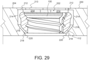
- Fig. 29 depicts an alternate embodiment of a plate 200 having an extension 212 that extends parallel to the upper surface 204.
- the extensions 212 may define a hole 213 that has a smaller cross dimension than the aperture 202.
- the pivot member 100 may be retracted or collapsed to allow for passage through the hole 213. Once disposed in the aperture 202, the pivot member 100 may be expanded such that the extension member 212 extending parallel to the upper surface 204 may restrict the pivot member 100 from being removed from the aperture 202.
- the pivot member 100 is disposed in and retained by the aperture 202. This arrangement may be established prior to the use of the plate 200 in a surgical operation. Because the pivot member 100 is retained within the aperture 202, a surgeon or other user during surgery may not be required to manipulate the pivot member 100 to dispose it relative to a fastener and/or the plate 200. In turn, the plate 200 may be provided as a unitary component to the surgeon for use in affixing the plate 200 to a bone of a patient without having the added complexity of alignment and engagement of the pivot member 100 relative to the plate 200.
- the outer surface 108 of the pivot member 100 is noncircular.
- the sidewall 210 of the aperture 202 includes at least a portion that is non-circular.
- the outer surface 108 and the sidewall 210 interface to restrict rotation of the pivot member 100 relative to the aperture 202.
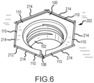
- the pivot member 100 includes a plurality of flats 110 that correspond to flat portions 214 of the aperture 202 as can be seen in Fig. 6 .
- Chamfers 114 may be provided between the flats 110 as can best be seen in Figs. 2-5 .
- the chamfers 114 may assist in facilitating pivoting of the pivot member 100 relative to the aperture 202 (e.g., to provide two degrees of freedom of movement of the pivot member 100 relative to the plate 200 as described above).
- the pivot member 100 includes a convex portion 112.
- the convex portion 112 is in conformal adjacent relation to a ramped surface 216.
- the ramped surface 216 extend along a flange 218 that extends from the sidewall 210 toward the reference axis 208.
- the flange 218 and ramped surface 216 comprise a bowled portion that receives the convex portion 112 of the pivot member 100 when the pivot member 100 is disposed in the aperture 202.
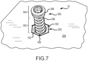
- a fastener 300 is shown relative to the pivot member 100 and plate 200.
- the pivot member 100, plate 200, and fastener 300 may comprise an orthopedic implant system 10.
- the fastener 300 may comprise a screw such as a surgical screw or the like.
- the fastener 300 may comprise a self-tapping screw, or include any other features common to surgical screws.
- the fastener 300 may comprise an elongate portion 302 at a distal portion of the fastener 300 and a head portion 304 at a proximal portion of the fastener 300.
- the elongate portion 302 may comprise threads 306.
- the fastener 300 may be in threaded engagement with corresponding threads disposed about the bore 102 of the pivot member 100.
- the threads 306 of the fastener 300 may be used to advance the fastener 300 relative to a bone of a patient for securing the fastener 300 to the bone after having passed through the pivot member 100 and plate 200.
- the head portion 304 may also comprise threads 308.
- the threads 308 may be the same pitch as the threads 306 of the elongate portion 302.
- the threads 308 on the head portion 304 may comprise a double thread.
- two threads of the same pitch may be provided on the head portion 304.
- the pitch of the threads 306 of the elongate portion 302 may be the same as the pitch of the threads 308 of the head portion 304 with the head portion 304 featuring a double thread. Both threads 306 and 308 may engage with the threads of the bore 102, or threads 308 on the head portion 304 alone may engage the threads of the bore 102.
- the threads 306 on the elongate portion 302 may be provided to engage the bone of a patient, yet may not contact the pivot member 100 as the fastener 300 is advanced relative thereto.
- the head portion 304 may have a sloped surface that defines a profile such that the diameter of the head increases toward the proximal end of the fastener 300.
- the head portion 304 may be frustoconical.
- the pitch diameter of the fastener 300 may increase toward the proximal end of the fastener 300.
- the interaction of the fastener 300 may result in locking of the pivot member 100 relative to the plate 200.
- the pivot member 100 may be expandable radially in relation to the fastener insertion axis 104.
- the interaction of the fastener 300 e.g., the head portion 304 thereof
- the outer surface 108 of the pivot member 100 may frictionally engage the sidewall 210 of the aperture 202.
- the frictional engagement of the outer surface 108 with the sidewall 210 may at least limit, and in some instances prevent, movement of the pivot member 100 relative to the plate 200.
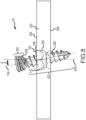
- the threaded engagement of the threads 308 of the head portion 304 of the fastener 300 may act on the bore 102 to radially expand the pivot member 100 relative to the aperture 202 to from a first configuration as shown in Fig. 6 to a second configuration as shown in Figs. 9 and 10 .
- the outer surface 108 is moveable relative to the conformal adjacent sidewall 210 of the aperture 202.
- the outer surface 108 of the pivot member 100 contactingly engages the sidewall 210.
- the head portion 304 may threadingly engage the bore 102 of the pivot member 100.
- the head portion 304 may have an increased diameter as compared to the elongate portion 302 (e.g., including potentially including a frustoconically shaped portion with increasing diameter along the head portion 304 in a proximal direction)
- the engagement of the head portion 304 with the pivot member 100 expands the pivot member 100 radially relative to the fastener insertion axis 104 to the second configuration as shown in Figs. 9 and 10 . That is, the second configuration of the pivot member 100 may be at a greater radial expansion than that of the first configuration.
- the outer surface 108 of the pivot member 100 engages the sidewall 210 of the aperture 202 to restrict movement of the pivot member 100 relative to the plate 200.
- the movement of the pivot member 100 relative to the plate 200 is fully restricted such that forces imparted by a surgeon, forces resulting from installation of the plate 200 to the bone of a patient, or forces that are imparted to the pivot member 100, plate 200, and fastener 300 once installed do not result in movement of the pivot member 100 relative to the plate 200.
- the head portion 304 threadably engages the bore 102 when the head portion 304 is advanced to the pivot member 100.
- the fastener 300 may be rigidly engaged with the pivot member 100 that is in turn frictionally engaged with the aperture 202.
- the conical or frustoconical shape of a head portion 304 without threads may also be used.
- the advancement of the fastener 300 relative to the bone of a patient causes compressive forces to act on the pivot member 100 such that the frustoconical head portion 304 still results in radial expansion of the pivot member 100 to frictionally engage the aperture 202 as illustrated in Fig. 9 .
- the fastener 300 may be lockingly engageable with the pivot member 100 by threaded interaction therebetween such that the fastener 300 is in turn loaded without compression forces acting between the fastener 300 and the plate 200.
- the fastener 300 may lacking locking threads to lock the fastener 300 to the pivot member 100 such that the fastener 300 may be loaded in compression to lock the pivot member 100 relative to the plate 200.
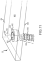
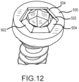
- Fig. 11 depicts a comparative example of an orthopedic implant system 20.
- the system 20 includes a plate 400, a pivot member 500, and a fastener 600.
- system 20 may include a fastener 600 that retains the pivot member 500 therewith.
- the pivot member 500 may pivot relative to the fastener 600 and may provide angulation of the fastener 600 while still allowing the pivot member 500 to be lockingly engaged with the plate 400 as will be described in greater detail below.
- the pivot member 500 may comprise a bore 502.
- the bore 502 may comprise a non-circular sidewall 504 that at least partially defines the bore 502.
- the head portion 602 may have an outer surface 604 that is correspondingly non-circular relative to the sidewall 504.
- the pivot member 500 may undergo corresponding rotational movement by interaction of the sidewall 504 and the outer surface 604.
- the outer surface 604 of the head portion 602 may be in conformal adjacent relation to the sidewall 504 of the bore 502.
- the outer surface 604 and the sidewall 504 may be curved to allow pivotal movement between the fastener 600 and the pivot member 500.
- the pivot member 500 may define a reference axis 506 about which the bore 502 extends.
- the fastener 600 may extend along a fastener insertion axis 606. Accordingly, the pivotal movement between the fastener 600 and the pivot member 500 may define an included angle ⁇ therebetween.
- the included angle ⁇ in the system 20 may include any of the characteristics described above in relation to system 10. That is, the included angle ⁇ may be defined at any radial position about the reference axis 606. In addition, the included angle ⁇ may be at least about 10 degrees in an embodiment or even at least about 15 degrees.
- the fastener 600 may be advanced through the aperture 402 of the plate 400.
- the elongate portion 604 of the fastener 600 may be advanced into the bone of a patient.
- the head portion 602 may be advanced toward the plate 400 such that the pivot member 500 may be disposed within the aperture 402.
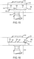
- Fig. 15 shows the fastener 600 is in position such that a portion of the pivot member 500 is disposed with in the aperture 402 of the plate 400.
- the pivot member 500 comprises a first locking feature on a distal portion thereof.
- the aperture 402 comprises a second locking feature on a proximal-facing portion of the aperture 402.
- the first locking feature on the pivot member 500 may correspond to the second locking feature of the aperture 402 so that the first locking feature and the second locking feature are engageable for locking interaction therebetween.
- the first locking feature of the pivot member 500 comprises a plurality of ramped surfaces 506.
- the second locking feature of the aperture 402 comprises a plurality of teeth 408.
- the fastener 600 As the fastener 600 is advanced relative to the bone of a patient, the fastener 600 also moves distally relative to the plate 400. Because the pivot member 500 is retained by the head portion 602 of the fastener 600, the distal movement of the fastener 600 brings the ramped surfaces 506 in contact with the teeth 408. As the fastener 600 is rotated, the ramped surfaces 506 travel along the teeth 408 in a ratcheting action as the fastener 600 is advanced.
- the teeth 408 Upon continued advancement of the fastener 600, the teeth 408 will interlockingly engage the ramped surfaces 506 as shown in Fig. 16 .
- the interlocking engagement between the ramped surfaces 506 and the teeth 408 may restrict rotation of the fastener 600 in a direction opposite the direction in which the fastener 600 is rotated as it is advanced.
- the pivot member 500 is clampingly engaged in the aperture 402 by the head portion 602 of the fastener 600.
- the interlocking engagement of the ramped surfaces 506 and the teeth 408 restrict rotation of the fastener 600 tending to withdraw the fastener 600 proximally.
- the fastener 600 remains clampingly engaged with the plate 400.
- the compressive forces acting between the fastener head 602 and the pivot member 500 create frictional engagement between the outer surface 604 of the head portion 602 and the sidewall 504 of the bore 502.
- the included angle ⁇ defined between the fastener insertion axis 606 and the reference axis 506 is maintained as further pivotal movement between the head portion 602 and the pivot member 500 is restricted or prevented based on the frictional interaction between the sidewall 504 and the outer surface 604.
- restricted from pivotal movement it is meant that the forces experienced during bone healing or movement by the patient will not cause such pivotal movement. That is, application of a large force (e.g., by a surgeon with assistance of a tool or the like) may be able to cause such pivotal movement to remove the hardware during a surgical procedure.
- FIG. 18 Another comparative example 22 of an orthopedic implant system 22 is shown.
- the system 22 comprises a plate 450, a pivot member 550, and a fastener 650.
- the pivot member 550 may be retainedly engaged with a head portion 652 of the fastener 600.
- the pivot member 550 may pivot relative to the fastener 650.
- the pivot member 550 may define a bore 552 that may extend along a reference axis.
- the fastener 650 may extend along a fastener insertion axis.
- the pivotal movement of the pivot member 550 relative to the fastener 650 may define an included angle between the reference axis and the fastener insertion axis as described above in relation to the system 20.
- the head portion 652 may comprise an outer surface 654. Additionally, the bore 552 may comprise a sidewall 554.
- the outer surface 654 may be disposed in conforming adjacent relation to the sidewall 554. In the comparative example of the system 22, the outer surface 654 may be arcuate both circumferentially about the fastener insertion axis and at least partially arcuate along the fastener insertion axis. That is, the outer surface 654 may be at least partially spherical.
- the sidewall 554 may be conformingly shaped relative to the outer surface 654 such that the sidewall 554 may be at least partially spherical as well.
- the pivot member 550 may pivot relative to the head portion 652.
- the fastener 600 may be advanced relative to the plate 450 such that the pivot member 552 is disposed within an aperture 452 of the plate 450 that extends from an upper surface 454 to a lower surface 456 of the plate 450.
- a first locking feature of the pivot member 550 may be disposed relative to a second locking feature of the plate 400.
- the pivot member 550 may comprise a ramped surface 556. This is more clearly seen in Fig. 21 , which depicts the position of the pivot member 550 in Fig. 20 without the plate 450 shown for clarity.
- a plurality of ramped surfaces 556 may also be provided without limitation.
- the aperture 452 comprises one or more shoulders 458.
- the fastener 650 when the fastener 650 is advanced relative to the plate 450 (e.g., by advancing a threaded elongate portion 654 of the fastener 650 into a bone of a patient), the pivot member 550 that is retained at the head portion 652 may be advanced relative to the aperture 452.
- the advancement of the fastener 650 may include rotation in a first direction (e.g., clockwise).
- the pivot member 550 may be disposed such that the ramped surfaces 556 are not contacting the shoulder 458 as shown in Fig. 20 .
- a second direction opposite the first direction may cause the ramped surfaces 556 to engage the shoulder 458 as shown in Fig. 22.
- Fig. 23 depicts the position of the pivot member 550 in the absence of the plate 450 for clarity.
- the ramped surfaces 556 may slidingly engage the shoulder 458, which may be inclined in corresponding relation to the ramped surfaces 556.
- the ramped surfaces 556 may slidingly engage to ride up the shoulder 458. This may cause the pivot member 550 to be urged away from the plate 450.
- the urging of the pivot member 550 away from the plate 450 may clampingly engage the plate 450 with the bone of the patient.
- the pivot member 550 may impart a clamping force on the head portion 652 of the fastener 650.
- the clamping force acting between the pivot member 550 and the fastener 650 may result in frictional engagement of the sidewall 454 of the aperture 452 with the outer surface 654 of the head portion 652. This frictional engagement may maintain the position of the fastener 650 relative to the pivot member 550.
- the shoulder 458 may include a lip 460.
- the lip 460 may be disposed such that a trialing edge 462 of the ramped surface 556 may pass over the lip 460.
- the ramped surface 556 may be disposed relative to the lip 460 such that rotation of the pivot member 550 in the first direction (i.e., tending to cause the pivot member to unclamp the plate 450 and fastener 650) may be restricted by the lip 460.
- the pivot member 550 may be restricted, and in some instances prevented, from relative movement with respect to the fastener 600.
- restricted relative movement may include prevention of such movement during bone healing or normal patient activities, but could be overcome by the force applied by a surgeon using a tool to remove the fastener 600.
- the rotation of the pivot member 550 in the second direction may be induced by interaction with a tool 700.
- the tool 700 may comprise projections 702 that correspondingly engage slots 704 provided on the pivot member 550.
- the tool 700 may be engaged with the pivot member 550 such that the projections 702 engage the slots 704.
- the tool 700 may be used to rotate the pivot member 550 to engage the ramped surfaces 556 with the shoulder 458 to impart the clamping forces as described above.
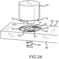
- FIGs. 25-28 another comparative example of an orthopedic plate system is depicted.
- the system depicted in Figs. 25-28 may include a plate 900 having a bore 902 extending from a top surface 904 to a bottom surface 906 of the plate 900.
- a fastener 850 may be provided that may pass through the bore 902 to engage the bone of the patient for fixation of the plate 900 relative to the bone of the patient.
- a pivot member 800 may be secured relative to a head portion 810 of the fastener 850.
- the pivot member 800 may be disposed between a head portion 810 and a ledge 814 that extends radially from the fastener 850.
- the pivot member 800 may become disposed within the aperture 902 of the plate 900. Thereafter, the pivot member 800 may be selectively radially expanded to lockingly engage the plate 900.
- the fastener 850 may include an elongate portion 812.
- the elongate portion 812 may comprise threads 818 that are engageable with the bone of the patient to advance the fastener 850 relative to the bone of the patient.
- the fastener 850 may include the head portion 810 which is disposed near a proximal end portion 824 of the fastener 850.
- the head portion 810 may be threadably engaged with the proximal end portion 824 of the fastener 850. Accordingly, the head portion 850 may be advanced distally or retracted proximally by corresponding respective rotation of the head portion 850 relative to the proximal end portion 824 of the fastener 850.
- the ledge 814 briefly described above may extend radially relative to a fastener insertion axis 804 that generally extends along the elongate portion 812.
- the ledge 814 may be extend about the fastener 850 circumferentially such that the ledge 814 defines a stop such that the pivot member 800 may not be advanced distally relative to the ledge 814.
- the pivot member 800 may be arranged such that the pivot member 800 is disposed between the head portion 810 and the ledge 814 to retainedly engaged the pivot member 800 therebetween.
- the pivot member 800 may be relatively easily disposed between the head portion 810 and the ledge 814 by removing the head portion 810 from the proximal end portion 824 of the fastener 850. Thereafter, the pivot member 800 may be disposed about the fastener 850 such that the fastener 850 extends relative to a bore 802 defined by the pivot member 800.
- the head portion 810 may be reengaged with the proximal end portion 824 by way of the threadable engagement provided therebetween.
- the engagement of the pivot member 800 relative to the fastener member 850 may be performed prior to a surgeon utilizing the fastener 850 to secure the plate 900 relative to the patient.
- the fastener 850 with the pivot member 800 disposed relative thereto may be provided for use by a surgeon as an integral unit or preconfigured subassembly such that the utilization of the fastener 850 and pivot member 800 are efficient to the surgeon.
- the proximal end portion 824 may include a first tool receiving portion 816.
- the first tool receiving portion 816 may comprise a hexagonally shaped recess that may accept a correspondingly hexagonally shaped tool portion.
- Other configurations of the first tool receiving portion 816 may be provided that allow for controllable rotation of the elongate portion 812 of the fastener 850.
- the head portion 810 may include one or more second tool receiving portions 822.
- the second tool receiving portions 822 may include cylindrical recesses provided in the head portion 810.
- the second tool receiving portions 822 may be distributed radially about the proximal portion of the head portion 810 such that the second tool receiving portions 822 are accessible from the proximal portion of the fastener 850. It may be appreciated that other configurations of the second tool receiving portions 822 may be provided. Specifically, any configuration that allows for engagement by a tool for controlled rotation of the head portion 810 may be provided without limitation.
- the first tool receiving portion 816 may be engaged by a tool portion that may in turn impart rotation of the fastener 850 about the fastener insertion axis 804. This may in turn caused threads 818 to engage the bone of the patient and be advanced relative thereto.
- the second tool receiving portions 822 may be engaged and correspondingly rotated to prevent relative rotation between the head portion 810 and the proximal end portion 824 of the fastener 850.
- the first tool receiving portion 816 may be engaged alone to advance the fastener 850.
- the head portion 810 may correspondingly rotate with the proximal end portion 824 absent engagement with the second tool receiving portions 822.
- the pivot member 800 that may be restrainedly engaged between the head portion 810 and the ledge 814 may also be advanced relative to the plate 900.
- the pivot member 800 may be advanced so that it is disposed within the aperture 902 of the plate 900.
- the aperture 902 of the plate 900 may include a neck portion 912.
- the pivot member 800 may also include an expansion slot 806 that allows for radial expansion and contraction of the pivot member 800 relative to the fastener insertion axis 804.
- the pivot member 800 may engage the neck portion 912.
- the pivot member 800 may be radially compressed such that the pivot member 800 a pass by the neck portion 912 into a pocket 914 of the aperture 902.
- the pocket 914 may be a spheroid shaped portion comprising a sidewall 910 of the aperture 902. This configuration in which the pivot member 800 is disposed in the pocket 914 of the aperture 902 shown in Fig. 26 .
- the head portion 810 may be engaged at the second tool receiving portion 822 to impart rotation of the head portion 810 relative to the proximal end portion 824 to advance the head portion 810 distally relative to the proximal end portion 824.
- the distal advancement of the head portion 810 may cause a ramped surface 820 of the head portion 810 to engage the bore 802 of the pivot member 800.
- the distal advancement of the head portion 810 may cause the ramped surface 822 cause the radial expansion of the pivot member 800 such that an outer surface 808 of the pivot member 800 frictionally engages the sidewall 910 of the pocket 914.
- the pivot member 800 may be lockingly engaged relative to the plate 900 by way of advancement of the head portion 810 relative to the proximal end portion 824 so as to urge the pivot member 800 and radial expansion against the sidewall 910.
- the fastener 850 may be inserted relative to the plate such that an angle ⁇ is included between the fastener insertion axis 804 and the reference axis 908.
- the fastener may be lockingly engaged relative to the plate at the angle ⁇ .
- the angle ⁇ may be at least about 15°.
- one or more tools may be provided for engagement of the first tool receiving portion 816 and the second tool receiving portion 822.
- a single integral tool may be provided that includes a corresponding first tool portion adapted for engagement of the first tool receiving portion 816 and a corresponding second tool portion adapted for engagement of the second tool receiving portions 822.
- the second tool portion may be movable relative to the first tool portion such that a user may choose to utilize the first tool portion alone, the second tool portion alone, or the first and second tool portions together. That is, the tool may allow for selective engagement of the first, second, and/or first and second tools with the respective tool receiving portion.
- a discrete first tool having a first tool portion corresponding to the first tool receiving portion 816 may be provided and a discrete second tool having a second tool portion corresponding to the second tool receiving portions 822 may be provided.
- the first tool may be utilized to advance the fastener 850 into the position shown in Fig. 26 .
- the first tool may be disengaged from the first tool receiving portion 816.
- the second tool may then be engaged with the second tool receiving portions 822 to rotate the head portion 810 relative to the proximal end portion 824 to distally advance the head portion 810 causing radial expansion of the pivot member 800.
Landscapes
- Health & Medical Sciences (AREA)
- Orthopedic Medicine & Surgery (AREA)
- Surgery (AREA)
- Life Sciences & Earth Sciences (AREA)
- Heart & Thoracic Surgery (AREA)
- Nuclear Medicine, Radiotherapy & Molecular Imaging (AREA)
- Engineering & Computer Science (AREA)
- Biomedical Technology (AREA)
- Medical Informatics (AREA)
- Molecular Biology (AREA)
- Animal Behavior & Ethology (AREA)
- General Health & Medical Sciences (AREA)
- Public Health (AREA)
- Veterinary Medicine (AREA)
- Neurology (AREA)
- Surgical Instruments (AREA)
Claims (15)
- Eine orthopädische Platte (200), die Folgendes umfasst:einen Plattenkörper, der sich zwischen einer oberen Oberfläche (204) und einer unteren Oberfläche (206) des Plattenkörpers erstreckt, eine Öffnung (202), die sich durch den Plattenkörper erstreckt, und ein Schwenkelement (100), das innerhalb der Öffnung (202) gehalten wird;wobeidie Öffnung (202) sich durch den Plattenkörper von der oberen Oberfläche (204) zur unteren Oberfläche (206) entlang einer Referenzachse (208) erstreckt, wobei die Öffnung (202) eine Seitenwand (210) aufweist, die sich kreisförmig um ein Inneres der Öffnung (202) erstreckt, wobei die Öffnung (202) einen nicht kreisförmigen Seitenwandabschnitt umfasst, wobei die Öffnung (202) eine rampenförmige Oberfläche (216) eines Flansches (218) umfasst, der sich relativ zur Öffnung (202) erstreckt;das in der Öffnung (202) gehaltene Schwenkelement (100) weist eine Außenfläche (108) auf, die der Seitenwand (210) entspricht, wobei das Schwenkelement (100) eine Bohrung (102) definiert, die sich entlang einer Befestigungselement-Einführachse (104) erstreckt, wobei die Bohrung (102) so konfiguriert ist, dass sie ein Befestigungselement (300) entlang der Befestigungselement-Einführachse (104) aufnehmen kann, wobei das Schwenkelement (100) eine Vielzahl von Abflachungen (110) aufweist, die sich um einen proximalen Umfang des Schwenkelements (100) erstrecken, und der nicht kreisförmige Seitenwandabschnitt entsprechend geformte Abflachungsabschnitte (214) umfasst und die Außenfläche (108) durch den nicht kreisförmigen Seitenwandabschnitt in Eingriff bringbar ist, um eine Drehung des Schwenkelements (100) um die Referenzachse (208) zu verhindern, wobei der Flansch (218) in einen distalen konvexen Abschnitt (112) des Schwenkelements (100) eingreift;wobei das Schwenkelement (100) zwischen einer ersten Konfiguration, die eine relative Bewegung zwischen der Außenfläche (108) und der Seitenwand (210) ermöglicht, und einer zweiten Konfiguration, in der die Außenfläche (108) reibschlüssig mit der Seitenwand (210) in Eingriff steht, um die Bewegung des Schwenkelements (100) relativ zur Öffnung (202) einzuschränken, angeordnet werden kann undwobei das Schwenkelement (100) in der ersten Konfiguration relativ zum Plattenkörper innerhalb der Öffnung (202) verschiebbar ist, um einen eingeschlossenen Winkel (θ) zwischen der Referenzachse (208) und der Befestigungselement-Einführachse (104) zu definieren.
- Die orthopädische Platte (200) nach Anspruch 1, wobei die zweite Konfiguration eine radiale Ausdehnung des Schwenkelements (100) umfasst, um die Seitenwand (210) reibschlüssig mit der Außenfläche (108) in Eingriff zu bringen.
- Die orthopädische Platte (200) nach Anspruch 2, wobei die Bohrung (102) eine geneigte Oberfläche aufweist, so dass ein Kopfabschnitt (304) des Befestigungselements (300) und die Bohrung (102) nach Aufnahme des Befestigungselements (300) in die Bohrung (102) einrasten können, um die radiale Ausdehnung zu bewirken.
- Die orthopädische Platte (200) nach Anspruch 2, wobei das Schwenkelement (100) einen Ausdehnungsschlitz (106) aufweist, der die radiale Ausdehnung des Schwenkelements (100) radial relativ zur Befestigungselement-Einführachse (104) ermöglicht.
- Die orthopädische Platte (200) nach Anspruch 4, wobei der Ausdehnungsschlitz (106) durch das Schwenkelement (100) in einer Richtung entlang der Befestigungselement-Einführachse (104) verläuft.
- Die orthopädische Platte (200) nach Anspruch 5, wobei der Ausdehnungsschlitz (106) vollständig durch das Schwenkelement (100) in einer Richtung entlang der Befestigungselement-Einführachse (104) verläuft.
- Die orthopädische Platte (200) nach Anspruch 1, wobei das Schwenkelement (100) Fasen (114) aufweist, die zwischen den mehreren Abflachungen verlaufen, um eine uneingeschränkte Schwenkbewegung des Schwenkelements (100) relativ zur orthopädischen Platte (200) in zwei Freiheitsgraden zu ermöglichen.
- Die orthopädische Platte (200) nach Anspruch 1, wobei die Bohrung (102) Gewinde aufweist, die zum Eingreifen in entsprechende Gewinde (308) an einem Kopfabschnitt (304) des Befestigungselements (300) geeignet sind.
- Die orthopädische Platte (200) nach Anspruch 1, wobei der eingeschlossene Winkel (θ) zwischen der Referenzachse (208) und der Befestigungselement-Einführachse (104) in mindestens einem Freiheitsgrad definierbar ist, wenn sich das Schwenkelement (100) in der ersten Konfiguration befindet.
- Die orthopädische Platte (200) nach Anspruch 9, wobei der eingeschlossene Winkel (θ) zwischen der Referenzachse (208) und der Befestigungselement-Einführachse (104) in mindestens zwei Freiheitsgraden definierbar ist.
- Die orthopädische Platte (200) nach Anspruch 10, wobei der eingeschlossene Winkel (θ) zwischen der Referenzachse (208) und der Befestigungselement-Einführachse (104) an jeder radialen Position um die Referenzachse (208) definierbar ist.
- Die orthopädische Platte (200) nach Anspruch 1, wobei der eingeschlossene Winkel (θ) zwischen der Referenzachse (208) und der Befestigungselement-Einführachse (104) mindestens etwa 10 Grad beträgt.
- Die orthopädische Platte (200) nach Anspruch 1, wobei der eingeschlossene Winkel (θ) zwischen der Referenzachse (208) und der Befestigungselement-Einführachse (104) mindestens etwa 15 Grad beträgt.
- Die orthopädische Platte (200) nach Anspruch 1, wobei der Plattenkörper Verlängerungen neben der oberen Oberfläche (204) umfasst, die sich relativ zur Öffnung (202) erstrecken, wobei sich die Verlängerungen relativ zur Öffnung (202) erstrecken, um das Schwenkelement (100) in der Öffnung (202) zu halten.
- Die orthopädische Platte (200) nach Anspruch 14, wobei die Verlängerungen in eine Position verschiebbar sind, in der sie sich relativ zur Öffnung (202) erstrecken, wenn das Schwenkelement (100) in die Öffnung (202) eingeführt wird, um das Schwenkelement (100) innerhalb der Öffnung (202) zu sichern.
Applications Claiming Priority (2)
| Application Number | Priority Date | Filing Date | Title |
|---|---|---|---|
| US201762509279P | 2017-05-22 | 2017-05-22 | |
| PCT/US2018/033730 WO2018217660A1 (en) | 2017-05-22 | 2018-05-21 | Variable angle orthopedic fasteners for fixation of an orthopedic implant |
Publications (3)
| Publication Number | Publication Date |
|---|---|
| EP3629960A1 EP3629960A1 (de) | 2020-04-08 |
| EP3629960A4 EP3629960A4 (de) | 2021-03-17 |
| EP3629960B1 true EP3629960B1 (de) | 2024-10-09 |
Family
ID=64395986
Family Applications (1)
| Application Number | Title | Priority Date | Filing Date |
|---|---|---|---|
| EP18804963.9A Active EP3629960B1 (de) | 2017-05-22 | 2018-05-21 | Orthopädische befestigungselemente mit variablem winkel zur fixierung eines orthopädischen implantats |
Country Status (4)
| Country | Link |
|---|---|
| US (3) | US11337738B2 (de) |
| EP (1) | EP3629960B1 (de) |
| AU (2) | AU2018273364B2 (de) |
| WO (1) | WO2018217660A1 (de) |
Families Citing this family (5)
| Publication number | Priority date | Publication date | Assignee | Title |
|---|---|---|---|---|
| GB201207975D0 (en) * | 2012-05-08 | 2012-06-20 | Ortho Solutions Ltd | Improvements in or relating to pelvic reconstruction |
| US11992227B2 (en) | 2018-03-05 | 2024-05-28 | Edge Surgical, Inc. | Handheld devices for use in medical procedures |
| US11504169B2 (en) | 2019-03-11 | 2022-11-22 | Edge Surgical, Inc. | Surgical depth instrument |
| JP2026511041A (ja) * | 2023-03-22 | 2026-04-10 | デピュイ・アイルランド・アンリミテッド・カンパニー | 係止ねじ適合のためのインサート |
| DE102024127782A1 (de) * | 2024-09-25 | 2026-03-26 | Karl Leibinger Asset Management Gmbh & Co. Kg | Osteosyntheseplatte sowie Verfahren zur Herstellung einer Osteosyntheseplatte |
Family Cites Families (14)
| Publication number | Priority date | Publication date | Assignee | Title |
|---|---|---|---|---|
| DE29701099U1 (de) * | 1997-01-23 | 1997-03-06 | Aesculap Ag, 78532 Tuttlingen | Stiftförmiges Halteelement für ein orthopädisches Haltesystem |
| US6605090B1 (en) * | 2000-10-25 | 2003-08-12 | Sdgi Holdings, Inc. | Non-metallic implant devices and intra-operative methods for assembly and fixation |
| ES2250307T3 (es) * | 2001-12-24 | 2006-04-16 | Synthes Ag Chur | Dispositivo para osteosintesis. |
| FR2908627B1 (fr) * | 2006-11-20 | 2009-07-03 | Tornier Sas | Dispositif prothetique ou d'osteosynthese a olive fendue |
| CA2768969C (en) * | 2009-07-24 | 2016-12-13 | Spinal USA LLC | Bone plate system and methods of using the same |
| US8632575B2 (en) * | 2010-03-03 | 2014-01-21 | Globus Medical | Low profile fastening assembly |
| ES2563756T3 (es) * | 2010-10-07 | 2016-03-16 | Biedermann Technologies Gmbh & Co. Kg | Conjunto de placa ósea con elemento guía |
| EP2736430B1 (de) * | 2011-09-14 | 2016-03-02 | Zimmer GmbH | Implantierbare vorrichtung |
| US9198769B2 (en) * | 2011-12-23 | 2015-12-01 | Pioneer Surgical Technology, Inc. | Bone anchor assembly, bone plate system, and method |
| US20130317554A1 (en) * | 2012-05-23 | 2013-11-28 | Thomas Purcell | Locking mechanism for an implantable medical device |
| KR101406398B1 (ko) | 2012-06-29 | 2014-06-13 | 인텔렉추얼디스커버리 주식회사 | 사용자 음원 평가 장치, 방법 및 기록 매체 |
| US9522024B2 (en) * | 2013-03-12 | 2016-12-20 | Blackstone Medical, Inc. | Orthopedic plate and screw apparatus |
| EP2932927B1 (de) | 2014-04-17 | 2017-09-20 | Biedermann Technologies GmbH & Co. KG | Knochenplatte mit vergrößertem Neigungswinkel für einen Knochenanker auf eine bevorzugte Seite |
| US10251685B2 (en) * | 2016-03-17 | 2019-04-09 | Stryker European Holdings I, Llc | Floating locking insert |
-
2018
- 2018-05-21 EP EP18804963.9A patent/EP3629960B1/de active Active
- 2018-05-21 US US16/628,638 patent/US11337738B2/en active Active
- 2018-05-21 AU AU2018273364A patent/AU2018273364B2/en active Active
- 2018-05-21 WO PCT/US2018/033730 patent/WO2018217660A1/en not_active Ceased
-
2022
- 2022-04-27 US US17/731,042 patent/US11950815B2/en active Active
- 2022-12-13 AU AU2022287576A patent/AU2022287576B2/en active Active
-
2024
- 2024-03-15 US US18/607,393 patent/US12262930B2/en active Active
Also Published As
| Publication number | Publication date |
|---|---|
| WO2018217660A1 (en) | 2018-11-29 |
| AU2018273364B2 (en) | 2022-09-29 |
| US11337738B2 (en) | 2022-05-24 |
| AU2018273364A1 (en) | 2019-12-05 |
| US12262930B2 (en) | 2025-04-01 |
| US20220280210A1 (en) | 2022-09-08 |
| EP3629960A1 (de) | 2020-04-08 |
| EP3629960A4 (de) | 2021-03-17 |
| US11950815B2 (en) | 2024-04-09 |
| US20200337748A1 (en) | 2020-10-29 |
| AU2022287576B2 (en) | 2024-03-07 |
| AU2022287576A1 (en) | 2023-02-02 |
| US20240261005A1 (en) | 2024-08-08 |
Similar Documents
| Publication | Publication Date | Title |
|---|---|---|
| US12262930B2 (en) | Variable angle orthopedic fasteners for fixation of an orthopedic implant | |
| US9427269B2 (en) | Locking screws and plates | |
| US10299837B2 (en) | Sacroiliac joint stabilization and fixation devices and related methods | |
| US20230200867A1 (en) | Stabilization systems | |
| US11786279B2 (en) | Modular spinal fixation device | |
| EP2939621B1 (de) | Schrauben einsetzinstrument | |
| US10918429B2 (en) | Fracture fixation system including locking cap and wire | |
| EP3284427B1 (de) | Hohlhandseitiges distales radiusstabilisierungssystem | |
| EP4025143B1 (de) | Knochenfixierungssystem mit befestigungselementen und demontagewerkzeug zum entkoppeln der befestigungselemente | |
| US9848925B2 (en) | Plate/screw locking mechanism devices, systems and methods | |
| US10213231B2 (en) | System and method for reducing and stabilizing a bone fracture |
Legal Events
| Date | Code | Title | Description |
|---|---|---|---|
| STAA | Information on the status of an ep patent application or granted ep patent |
Free format text: STATUS: THE INTERNATIONAL PUBLICATION HAS BEEN MADE |
|
| PUAI | Public reference made under article 153(3) epc to a published international application that has entered the european phase |
Free format text: ORIGINAL CODE: 0009012 |
|
| STAA | Information on the status of an ep patent application or granted ep patent |
Free format text: STATUS: REQUEST FOR EXAMINATION WAS MADE |
|
| 17P | Request for examination filed |
Effective date: 20191212 |
|
| AK | Designated contracting states |
Kind code of ref document: A1 Designated state(s): AL AT BE BG CH CY CZ DE DK EE ES FI FR GB GR HR HU IE IS IT LI LT LU LV MC MK MT NL NO PL PT RO RS SE SI SK SM TR |
|
| AX | Request for extension of the european patent |
Extension state: BA ME |
|
| DAV | Request for validation of the european patent (deleted) | ||
| DAX | Request for extension of the european patent (deleted) | ||
| A4 | Supplementary search report drawn up and despatched |
Effective date: 20210215 |
|
| RIC1 | Information provided on ipc code assigned before grant |
Ipc: A61B 17/80 20060101AFI20210209BHEP Ipc: A61B 17/88 20060101ALI20210209BHEP Ipc: A61B 17/86 20060101ALI20210209BHEP |
|
| RAP3 | Party data changed (applicant data changed or rights of an application transferred) |
Owner name: MCGINLEY ENGINEERED SOLUTIONS, LLC |
|
| RIN1 | Information on inventor provided before grant (corrected) |
Inventor name: MCGINLEY, JOSEPH C. Inventor name: PALAZZOLO, VINCENT Inventor name: WARREN, BEN Inventor name: JOHNSON, ADAM |
|
| STAA | Information on the status of an ep patent application or granted ep patent |
Free format text: STATUS: EXAMINATION IS IN PROGRESS |
|
| 17Q | First examination report despatched |
Effective date: 20230615 |
|
| GRAP | Despatch of communication of intention to grant a patent |
Free format text: ORIGINAL CODE: EPIDOSNIGR1 |
|
| STAA | Information on the status of an ep patent application or granted ep patent |
Free format text: STATUS: GRANT OF PATENT IS INTENDED |
|
| INTG | Intention to grant announced |
Effective date: 20240513 |
|
| GRAS | Grant fee paid |
Free format text: ORIGINAL CODE: EPIDOSNIGR3 |
|
| GRAA | (expected) grant |
Free format text: ORIGINAL CODE: 0009210 |
|
| STAA | Information on the status of an ep patent application or granted ep patent |
Free format text: STATUS: THE PATENT HAS BEEN GRANTED |
|
| P01 | Opt-out of the competence of the unified patent court (upc) registered |
Free format text: CASE NUMBER: APP_47901/2024 Effective date: 20240820 |
|
| AK | Designated contracting states |
Kind code of ref document: B1 Designated state(s): AL AT BE BG CH CY CZ DE DK EE ES FI FR GB GR HR HU IE IS IT LI LT LU LV MC MK MT NL NO PL PT RO RS SE SI SK SM TR |
|
| REG | Reference to a national code |
Ref country code: CH Ref legal event code: EP |
|
| REG | Reference to a national code |
Ref country code: DE Ref legal event code: R096 Ref document number: 602018075260 Country of ref document: DE |
|
| REG | Reference to a national code |
Ref country code: IE Ref legal event code: FG4D |
|
| REG | Reference to a national code |
Ref country code: LT Ref legal event code: MG9D |
|
| REG | Reference to a national code |
Ref country code: NL Ref legal event code: MP Effective date: 20241009 |
|
| REG | Reference to a national code |
Ref country code: AT Ref legal event code: MK05 Ref document number: 1729712 Country of ref document: AT Kind code of ref document: T Effective date: 20241009 |
|
| PG25 | Lapsed in a contracting state [announced via postgrant information from national office to epo] |
Ref country code: NL Free format text: LAPSE BECAUSE OF FAILURE TO SUBMIT A TRANSLATION OF THE DESCRIPTION OR TO PAY THE FEE WITHIN THE PRESCRIBED TIME-LIMIT Effective date: 20241009 |
|
| PG25 | Lapsed in a contracting state [announced via postgrant information from national office to epo] |
Ref country code: NL Free format text: LAPSE BECAUSE OF FAILURE TO SUBMIT A TRANSLATION OF THE DESCRIPTION OR TO PAY THE FEE WITHIN THE PRESCRIBED TIME-LIMIT Effective date: 20241009 |
|
| PG25 | Lapsed in a contracting state [announced via postgrant information from national office to epo] |
Ref country code: HR Free format text: LAPSE BECAUSE OF FAILURE TO SUBMIT A TRANSLATION OF THE DESCRIPTION OR TO PAY THE FEE WITHIN THE PRESCRIBED TIME-LIMIT Effective date: 20241009 Ref country code: IS Free format text: LAPSE BECAUSE OF FAILURE TO SUBMIT A TRANSLATION OF THE DESCRIPTION OR TO PAY THE FEE WITHIN THE PRESCRIBED TIME-LIMIT Effective date: 20250209 Ref country code: PT Free format text: LAPSE BECAUSE OF FAILURE TO SUBMIT A TRANSLATION OF THE DESCRIPTION OR TO PAY THE FEE WITHIN THE PRESCRIBED TIME-LIMIT Effective date: 20250210 |
|
| PG25 | Lapsed in a contracting state [announced via postgrant information from national office to epo] |
Ref country code: FI Free format text: LAPSE BECAUSE OF FAILURE TO SUBMIT A TRANSLATION OF THE DESCRIPTION OR TO PAY THE FEE WITHIN THE PRESCRIBED TIME-LIMIT Effective date: 20241009 |
|
| PG25 | Lapsed in a contracting state [announced via postgrant information from national office to epo] |
Ref country code: BG Free format text: LAPSE BECAUSE OF FAILURE TO SUBMIT A TRANSLATION OF THE DESCRIPTION OR TO PAY THE FEE WITHIN THE PRESCRIBED TIME-LIMIT Effective date: 20241009 |
|
| PG25 | Lapsed in a contracting state [announced via postgrant information from national office to epo] |
Ref country code: ES Free format text: LAPSE BECAUSE OF FAILURE TO SUBMIT A TRANSLATION OF THE DESCRIPTION OR TO PAY THE FEE WITHIN THE PRESCRIBED TIME-LIMIT Effective date: 20241009 |
|
| PG25 | Lapsed in a contracting state [announced via postgrant information from national office to epo] |
Ref country code: NO Free format text: LAPSE BECAUSE OF FAILURE TO SUBMIT A TRANSLATION OF THE DESCRIPTION OR TO PAY THE FEE WITHIN THE PRESCRIBED TIME-LIMIT Effective date: 20250109 |
|
| PG25 | Lapsed in a contracting state [announced via postgrant information from national office to epo] |
Ref country code: LV Free format text: LAPSE BECAUSE OF FAILURE TO SUBMIT A TRANSLATION OF THE DESCRIPTION OR TO PAY THE FEE WITHIN THE PRESCRIBED TIME-LIMIT Effective date: 20241009 Ref country code: GR Free format text: LAPSE BECAUSE OF FAILURE TO SUBMIT A TRANSLATION OF THE DESCRIPTION OR TO PAY THE FEE WITHIN THE PRESCRIBED TIME-LIMIT Effective date: 20250110 Ref country code: AT Free format text: LAPSE BECAUSE OF FAILURE TO SUBMIT A TRANSLATION OF THE DESCRIPTION OR TO PAY THE FEE WITHIN THE PRESCRIBED TIME-LIMIT Effective date: 20241009 |
|
| PG25 | Lapsed in a contracting state [announced via postgrant information from national office to epo] |
Ref country code: PL Free format text: LAPSE BECAUSE OF FAILURE TO SUBMIT A TRANSLATION OF THE DESCRIPTION OR TO PAY THE FEE WITHIN THE PRESCRIBED TIME-LIMIT Effective date: 20241009 |
|
| PG25 | Lapsed in a contracting state [announced via postgrant information from national office to epo] |
Ref country code: RS Free format text: LAPSE BECAUSE OF FAILURE TO SUBMIT A TRANSLATION OF THE DESCRIPTION OR TO PAY THE FEE WITHIN THE PRESCRIBED TIME-LIMIT Effective date: 20250109 |
|
| PG25 | Lapsed in a contracting state [announced via postgrant information from national office to epo] |
Ref country code: SM Free format text: LAPSE BECAUSE OF FAILURE TO SUBMIT A TRANSLATION OF THE DESCRIPTION OR TO PAY THE FEE WITHIN THE PRESCRIBED TIME-LIMIT Effective date: 20241009 |
|
| PGFP | Annual fee paid to national office [announced via postgrant information from national office to epo] |
Ref country code: DE Payment date: 20250531 Year of fee payment: 8 |
|
| PG25 | Lapsed in a contracting state [announced via postgrant information from national office to epo] |
Ref country code: DK Free format text: LAPSE BECAUSE OF FAILURE TO SUBMIT A TRANSLATION OF THE DESCRIPTION OR TO PAY THE FEE WITHIN THE PRESCRIBED TIME-LIMIT Effective date: 20241009 |
|
| PGFP | Annual fee paid to national office [announced via postgrant information from national office to epo] |
Ref country code: GB Payment date: 20250408 Year of fee payment: 8 |
|
| REG | Reference to a national code |
Ref country code: DE Ref legal event code: R097 Ref document number: 602018075260 Country of ref document: DE |
|
| PG25 | Lapsed in a contracting state [announced via postgrant information from national office to epo] |
Ref country code: EE Free format text: LAPSE BECAUSE OF FAILURE TO SUBMIT A TRANSLATION OF THE DESCRIPTION OR TO PAY THE FEE WITHIN THE PRESCRIBED TIME-LIMIT Effective date: 20241009 |
|
| PGFP | Annual fee paid to national office [announced via postgrant information from national office to epo] |
Ref country code: FR Payment date: 20250415 Year of fee payment: 8 |
|
| PG25 | Lapsed in a contracting state [announced via postgrant information from national office to epo] |
Ref country code: RO Free format text: LAPSE BECAUSE OF FAILURE TO SUBMIT A TRANSLATION OF THE DESCRIPTION OR TO PAY THE FEE WITHIN THE PRESCRIBED TIME-LIMIT Effective date: 20241009 |
|
| PG25 | Lapsed in a contracting state [announced via postgrant information from national office to epo] |
Ref country code: SK Free format text: LAPSE BECAUSE OF FAILURE TO SUBMIT A TRANSLATION OF THE DESCRIPTION OR TO PAY THE FEE WITHIN THE PRESCRIBED TIME-LIMIT Effective date: 20241009 |
|
| PG25 | Lapsed in a contracting state [announced via postgrant information from national office to epo] |
Ref country code: CZ Free format text: LAPSE BECAUSE OF FAILURE TO SUBMIT A TRANSLATION OF THE DESCRIPTION OR TO PAY THE FEE WITHIN THE PRESCRIBED TIME-LIMIT Effective date: 20241009 |
|
| PG25 | Lapsed in a contracting state [announced via postgrant information from national office to epo] |
Ref country code: IT Free format text: LAPSE BECAUSE OF FAILURE TO SUBMIT A TRANSLATION OF THE DESCRIPTION OR TO PAY THE FEE WITHIN THE PRESCRIBED TIME-LIMIT Effective date: 20241009 |
|
| PLBE | No opposition filed within time limit |
Free format text: ORIGINAL CODE: 0009261 |
|
| STAA | Information on the status of an ep patent application or granted ep patent |
Free format text: STATUS: NO OPPOSITION FILED WITHIN TIME LIMIT |
|
| PG25 | Lapsed in a contracting state [announced via postgrant information from national office to epo] |
Ref country code: SE Free format text: LAPSE BECAUSE OF FAILURE TO SUBMIT A TRANSLATION OF THE DESCRIPTION OR TO PAY THE FEE WITHIN THE PRESCRIBED TIME-LIMIT Effective date: 20241009 |
|
| 26N | No opposition filed |
Effective date: 20250710 |
|
| REG | Reference to a national code |
Ref country code: CH Ref legal event code: H13 Free format text: ST27 STATUS EVENT CODE: U-0-0-H10-H13 (AS PROVIDED BY THE NATIONAL OFFICE) Effective date: 20251223 |
|
| PG25 | Lapsed in a contracting state [announced via postgrant information from national office to epo] |
Ref country code: LU Free format text: LAPSE BECAUSE OF NON-PAYMENT OF DUE FEES Effective date: 20250521 |
|
| PG25 | Lapsed in a contracting state [announced via postgrant information from national office to epo] |
Ref country code: CH Free format text: LAPSE BECAUSE OF NON-PAYMENT OF DUE FEES Effective date: 20250531 |
|
| REG | Reference to a national code |
Ref country code: BE Ref legal event code: MM Effective date: 20250531 |
|
| PG25 | Lapsed in a contracting state [announced via postgrant information from national office to epo] |
Ref country code: MC Free format text: LAPSE BECAUSE OF FAILURE TO SUBMIT A TRANSLATION OF THE DESCRIPTION OR TO PAY THE FEE WITHIN THE PRESCRIBED TIME-LIMIT Effective date: 20241009 |
|
| PG25 | Lapsed in a contracting state [announced via postgrant information from national office to epo] |
Ref country code: IE Free format text: LAPSE BECAUSE OF NON-PAYMENT OF DUE FEES Effective date: 20250521 |
|
| PG25 | Lapsed in a contracting state [announced via postgrant information from national office to epo] |
Ref country code: BE Free format text: LAPSE BECAUSE OF NON-PAYMENT OF DUE FEES Effective date: 20250531 |