EP3629600B1 - Hörgerät mit einer von dem hörgerät ausgehenden antenne - Google Patents
Hörgerät mit einer von dem hörgerät ausgehenden antenne Download PDFInfo
- Publication number
- EP3629600B1 EP3629600B1 EP18197790.1A EP18197790A EP3629600B1 EP 3629600 B1 EP3629600 B1 EP 3629600B1 EP 18197790 A EP18197790 A EP 18197790A EP 3629600 B1 EP3629600 B1 EP 3629600B1
- Authority
- EP
- European Patent Office
- Prior art keywords
- antenna
- hearing device
- faceplate
- ear
- hearing
- Prior art date
- Legal status (The legal status is an assumption and is not a legal conclusion. Google has not performed a legal analysis and makes no representation as to the accuracy of the status listed.)
- Active
Links
Images


Classifications
-
- H—ELECTRICITY
- H04—ELECTRIC COMMUNICATION TECHNIQUE
- H04R—LOUDSPEAKERS, MICROPHONES, GRAMOPHONE PICK-UPS OR LIKE ACOUSTIC ELECTROMECHANICAL TRANSDUCERS; ELECTRIC HEARING AIDS; PUBLIC ADDRESS SYSTEMS
- H04R25/00—Electric hearing aids
-
- H—ELECTRICITY
- H04—ELECTRIC COMMUNICATION TECHNIQUE
- H04R—LOUDSPEAKERS, MICROPHONES, GRAMOPHONE PICK-UPS OR LIKE ACOUSTIC ELECTROMECHANICAL TRANSDUCERS; ELECTRIC HEARING AIDS; PUBLIC ADDRESS SYSTEMS
- H04R25/00—Electric hearing aids
- H04R25/55—Electric hearing aids using an external connection, either wireless or wired
- H04R25/554—Electric hearing aids using an external connection, either wireless or wired using a wireless connection, e.g. between microphone and amplifier or using Tcoils
-
- H—ELECTRICITY
- H01—ELECTRIC ELEMENTS
- H01Q—ANTENNAS, i.e. RADIO AERIALS
- H01Q1/00—Details of, or arrangements associated with, antennas
- H01Q1/27—Adaptation for use in or on movable bodies
- H01Q1/273—Adaptation for carrying or wearing by persons or animals
-
- H—ELECTRICITY
- H01—ELECTRIC ELEMENTS
- H01Q—ANTENNAS, i.e. RADIO AERIALS
- H01Q1/00—Details of, or arrangements associated with, antennas
- H01Q1/48—Earthing means; Earth screens; Counterpoises
-
- H—ELECTRICITY
- H01—ELECTRIC ELEMENTS
- H01Q—ANTENNAS, i.e. RADIO AERIALS
- H01Q9/00—Electrically-short antennas having dimensions not more than twice the operating wavelength and consisting of conductive active radiating elements
-
- H—ELECTRICITY
- H04—ELECTRIC COMMUNICATION TECHNIQUE
- H04R—LOUDSPEAKERS, MICROPHONES, GRAMOPHONE PICK-UPS OR LIKE ACOUSTIC ELECTROMECHANICAL TRANSDUCERS; ELECTRIC HEARING AIDS; PUBLIC ADDRESS SYSTEMS
- H04R25/00—Electric hearing aids
- H04R25/60—Mounting or interconnection of hearing aid parts, e.g. inside tips, housings or to ossicles
- H04R25/604—Mounting or interconnection of hearing aid parts, e.g. inside tips, housings or to ossicles of acoustic or vibrational transducers
-
- H—ELECTRICITY
- H04—ELECTRIC COMMUNICATION TECHNIQUE
- H04R—LOUDSPEAKERS, MICROPHONES, GRAMOPHONE PICK-UPS OR LIKE ACOUSTIC ELECTROMECHANICAL TRANSDUCERS; ELECTRIC HEARING AIDS; PUBLIC ADDRESS SYSTEMS
- H04R25/00—Electric hearing aids
- H04R25/65—Housing parts, e.g. shells, tips or moulds, or their manufacture
-
- H—ELECTRICITY
- H04—ELECTRIC COMMUNICATION TECHNIQUE
- H04R—LOUDSPEAKERS, MICROPHONES, GRAMOPHONE PICK-UPS OR LIKE ACOUSTIC ELECTROMECHANICAL TRANSDUCERS; ELECTRIC HEARING AIDS; PUBLIC ADDRESS SYSTEMS
- H04R2225/00—Details of deaf aids covered by H04R25/00, not provided for in any of its subgroups
- H04R2225/025—In the ear hearing aids [ITE] hearing aids
-
- H—ELECTRICITY
- H04—ELECTRIC COMMUNICATION TECHNIQUE
- H04R—LOUDSPEAKERS, MICROPHONES, GRAMOPHONE PICK-UPS OR LIKE ACOUSTIC ELECTROMECHANICAL TRANSDUCERS; ELECTRIC HEARING AIDS; PUBLIC ADDRESS SYSTEMS
- H04R2225/00—Details of deaf aids covered by H04R25/00, not provided for in any of its subgroups
- H04R2225/51—Aspects of antennas or their circuitry in or for hearing aids
-
- H—ELECTRICITY
- H04—ELECTRIC COMMUNICATION TECHNIQUE
- H04R—LOUDSPEAKERS, MICROPHONES, GRAMOPHONE PICK-UPS OR LIKE ACOUSTIC ELECTROMECHANICAL TRANSDUCERS; ELECTRIC HEARING AIDS; PUBLIC ADDRESS SYSTEMS
- H04R2460/00—Details of hearing devices, i.e. of ear- or headphones covered by H04R1/10 or H04R5/033 but not provided for in any of their subgroups, or of hearing aids covered by H04R25/00 but not provided for in any of its subgroups
- H04R2460/17—Hearing device specific tools used for storing or handling hearing devices or parts thereof, e.g. placement in the ear, replacement of cerumen barriers, repair, cleaning hearing devices
-
- H—ELECTRICITY
- H04—ELECTRIC COMMUNICATION TECHNIQUE
- H04R—LOUDSPEAKERS, MICROPHONES, GRAMOPHONE PICK-UPS OR LIKE ACOUSTIC ELECTROMECHANICAL TRANSDUCERS; ELECTRIC HEARING AIDS; PUBLIC ADDRESS SYSTEMS
- H04R25/00—Electric hearing aids
- H04R25/55—Electric hearing aids using an external connection, either wireless or wired
- H04R25/552—Binaural
Definitions
- the present disclosure relates to hearing devices for compensating a hearing loss of a user, particularly hearing devices having wireless communication capabilities and thus hearing devices comprising antennas for communication.
- the present disclosure further relates to a hearing device comprising a hearing device shell, the shell comprising a microphone configured to receive sound, a processing unit configured to provide a processed audio signal for compensating for a hearing loss of a user, a wireless communication unit configured for wireless communication.
- the hearing device further comprises a faceplate and an antenna for emission and reception of an electromagnetic field, the antenna extending through the faceplate.
- the hearing device may be used in a binaural hearing device system. During operation, the hearing device is worn in the ear of a user for alleviating a hearing loss of the user.
- Hearing devices are very small and delicate devices and comprise many electronic and metallic components contained in a housing or shell small enough to fit in the ear canal of a human or be located behind the outer ear.
- the many electronic and metallic components in combination with the small size of the hearing device housing or shell impose high design constraints on radio frequency antennas to be used in hearing devices with wireless communication capabilities.
- the antenna in the hearing device must be designed to achieve a satisfactory performance despite these limitations and other narrow design constraints imposed by the size of the hearing device.
- the requirements to the quality of the communication between the hearing devices in the binaural hearing device system are ever increasing, and include demands for low latency and low noise, increasing the requests for effective antennas in the hearing devices.
- US 2018/0084351 A1 discloses a hearing device to be worn in an ear of a wearer to perform wireless communication.
- the hearing device includes a housing, hearing electronics within the housing, and an inverted F antenna or loop antenna disposed at least partially in the housing and configured for performing 2.4 GHz wireless communication.
- WO 2018/024392 A1 relates to a hearing aid that can be inserted into the ear of a hearing aid wearer, comprising a housing and at least one hearing aid component which is arranged in and/or on the housing and is made completely or partially of metal, wherein said hearing aid component or the metallic proportion of this hearing aid component forms in a secondary function an RF antenna, and wherein said hearing aid component has a main function which is different from the antenna function.
- EP 2 088 804 A1 discloses a hearing assistance device which provides sound to the ear of a user, the device comprising a housing, hearing assistance electronics enclosed in the housing, an acoustic transducer adapted to be worn in the ear, a cable assembly adapted to connect the acoustic transducer to the hearing assistance electronics, a wireless communications receiver connected to the hearing assistance electronics, and an antenna comprising one or more conductors forming at least a portion of the cable assembly.
- Further hearing devices comprising antennas are e.g. disclosed by WO 2018/024377 A1 and US 2010/020994 A1 .
- the hearing devices may be configured for wireless communication in an ISM frequency band.
- the RF antenna functionality may be implemented for operation at a frequency of at least 400 MHz, such as at a frequency of between 800 MHz and 6 GHz.
- Radio connectivity between hearing devices allows for advanced binaural signal processing when the important ear-to-ear (E2E) link is ensured.
- the hearing devices may be connected to a plethora of accessories, either body-worn or being placed in the user's proximity, and hence to the Internet as part of the so-called Internet-of-things (IoT).
- IoT Internet-of-things
- ISM Industrial, Scientific, Medical
- BLE Bluetooth Low Energy
- ZigBee ZigBee
- the E2E link is particularly demanding in terms of requirements on the wearable antenna design and performance.
- the antenna may exhibit optimal radiation efficiency, bandwidth, polarization, and radiation pattern, while the physical volume available for the design is extremely reduced, as most times space comes at a premium in wearable devices such as hearing devices, in particular in-the-ear (ITE) hearing devices.
- mass production and industrial design needs provide a desire that the antenna may also be low-profile, lightweight, and inexpensive to manufacture.
- the antenna polarization characteristic may be an important performance parameter. More overall constrains may also be relevant. In fact, antenna efficiency may be seriously jeopardized by the proximity of the antenna to the human head, as the body tissues have very high losses around 2.4 GHz due to their high water content.
- a large bandwidth is hard to achieve as well for an electrically small antenna (ESA) due to its fundamental limits.
- ESA electrically small antenna
- the bandwidth may cover at least the whole 2.4 GHz ISM band, but a larger bandwidth may help to compensate for the detuning of the antenna caused by the effects of the body, effects which varies across users.
- the hearing device comprises a microphone configured to receive sound.
- the hearing device comprises a processing unit configured to provide a processed audio signal for compensating for a hearing loss of a user.
- the hearing device comprises a wireless communication unit configured for wireless communication.
- the hearing device is an in-the-ear hearing device comprising a hearing device shell.
- the hearing device shell comprises a microphone configured to receive an audio signal, a signal processor configured to process the audio signal for compensating a hearing loss of a user, a wireless communication unit and a feeding network.
- the wireless communications unit is connected to the signal processor.
- the hearing device further comprises a faceplate positioned at the hearing device shell.
- the hearing device comprises an antenna for emission and reception of an electromagnetic field and being interconnected with the wireless communications unit.
- the antenna has a first end being fed from the feeding network.
- the antenna extends through the faceplate at a first position of the faceplate.
- At least a part of the antenna extending from the faceplate is arch-shaped and a second end of the antenna is an open end, such as an electrically open end.
- a second end of the antenna is interconnected to a ground potential. In some embodiments, a second end of the antenna is interconnected to a ground potential through a controlled impedance.
- a second end of the antenna is interconnected to the wireless communication unit.
- the second end of the antenna extends through the faceplate through a second through-hole of the faceplate to interconnect with the wireless communication unit.
- the hearing device shell is often times custom made to account for different structures of the inner canal, meatus and/or concha among different people.
- a hearing device shell is typically made by taking impressions of a user's ear, and have a custom hearing device shell manufactured so as to fit in the ear of a user.
- electronic hearing components are fit into an open end of the shell and the shell is closed by a faceplate.
- the faceplate may be fastened to the hearing device shell in any known way, e.g. by gluing, molding, press-fitting, etc.
- the faceplate is configured with battery door to provide access to a battery of the hearing device.
- the electronic hearing components includes for example the microphone, the signal processor, the wireless communication unit and the feeding network.
- the hearing device comprises an antenna for emission and reception of an electromagnetic field and being interconnected with the wireless communications unit.
- the antenna is an electric antenna, and the antenna has a first end being fed from the feeding network.
- the feeding network is positioned within the hearing device shell while the antenna extends from the feeding network through the faceplate at a first position of the faceplate.
- the faceplate comprises a through-hole at the first position to allow the antenna to extend through the faceplate.
- the faceplate has an inner side facing towards the hearing device shell and an outer side facing towards the surroundings.
- the feeding network provides a feed for the antenna at the faceplate.
- the second end of the antenna is interconnected to a ground potential, such as connected to a ground potential through a controlled impedance.
- the controlled impedance may comprise an inductor or a capacitor.
- the second end of the antenna is connected to the faceplate. In some embodiments, the second end of the antenna is connected to the faceplate without extending through the faceplate. In some embodiments, the second end of the antenna is connected to the faceplate at the outer side of the faceplate. In embodiments according to the invention, the second end of the antenna is interconnected to the faceplate at a second position of the faceplate.
- the second end of the antenna is interconnected to a ground potential at the faceplate, such as connected to a ground potential at the outer side of the faceplate.
- the part of the antenna extending from the faceplate has a first section extending from the first position along a first axis being parallel, such as substantially parallel, to an ear-to-ear axis of a user when the hearing device is positioned in the operational position in the ear of a user.
- a first angle between the first axis and the ear-to-ear axis is less than 25°, such as less than 10°.
- the first angle may be zero.
- the first angle may be between 0° and 25°.
- the part of the antenna extending from the faceplate may have a second section. In some embodiments the second section is extending in a direction parallel to the faceplate, such as substantially parallel to the faceplate.
- the second section extends in a direction along a second axis, the second axis forming a second angle with the faceplate, the second angle being less than 25°, such as less than 10°.
- the second angle may be between 0° and 25°.
- the second section of the antenna has a curvature different from zero.
- the second section may have concave shape.
- the second section may have a convex shape.
- the second section may have an arch-shape.
- the antenna further has a third section extending parallel to the first axis, such as substantially parallel to the first axis, and being interconnected with the faceplate at the second position of the faceplate.
- parallel such as substantial parallel, may imply that a third angle between the third section and the first axis is less than 25°, such as less than 10°.
- the third angle may be zero.
- the third angle may be between 0° and 25°.
- the part of the antenna extending from the faceplate is a U formed shaped or an inverse U formed shape ⁇ , a circular shape or an elliptical shape.
- the first section, the second section and third section of the antenna has a U formed or inverse U formed shape.
- the first section, the second section and third section of the antenna forms at least a part of a circular shape or an elliptical shape. It is envisaged that the antenna extending from the faceplate may have any shape and is not limited to the herein suggested shapes.
- the feeding network comprises one or more electric components providing a feed for the antenna.
- the feeding network is configured to provide a single ended feed.
- the feeding network is configured to provide a differential feed.
- the feeding network provides impedance matching for the antenna.
- the impedance matching for the antenna may include matching the impedance of the wireless communication unit to the combined impedance of the antenna and feedline.
- the feeding network comprises a balun.
- the feeding network comprises one or more controlled impedances, including capacitors, inductors and/or transmission lines, configured to optimize antenna parameters including antenna impedance matching.
- the feeding network may comprise an antenna matching network.
- the feeding network may comprise antenna matching components.
- the feeding network may comprise a feeding circuit configured to provide a feed for the antenna.
- the feeding network is located in the hearing device shell adjacent to the faceplate. It is an advantage of having the feeding network, and thus the feed for the antenna, provided adjacent the faceplate to allow for the part of the antenna extending between the feed and the through-hole of the faceplate to be as short as possible. Hereby, the length of the part of the antenna extending from the faceplate is maximized.
- a current in the antenna has a maximum in a section of the antenna extending from the feeding network. In some embodiments, a current in the antenna has a maximum proximate the first section of the antenna. In some embodiments, the current in the antenna is larger in the first section of the antenna than in the second section of the antenna.
- the antenna is an electrical antenna. In some embodiments, the antenna is a monopole antenna. In some embodiments, the antenna is a resonant antenna, such as an antenna configured to emit an electromagnetic field in a wavelength range about a resonance frequency.
- the length of the antenna is defined in relation to a wavelength ⁇ of the electromagnetic radiation to be emitted from and received by the hearing device when it is positioned at its intended operational position at the ear of a user.
- the hearing device is typically configured to emit and receive electromagnetic radiation within a specific frequency range or band.
- the frequency band is provided so as to include a resonance frequency for the antenna elements.
- the length of the antenna elements are optimized for use within such specific frequency bands, such as in a band about, or extending from, a peak resonant frequency.
- the length of the resonating element in free air is selected to correspond to an odd multiple of a quarter-wavelength, ⁇ /4, of a wavelength ⁇ of the electromagnetic radiation to be emitted from the hearing device.
- the length of the antenna is selected to optimize the antenna for use at a specific frequency or within a specific frequency band, such as selected to provide an optimum resonance at a specific frequency, such as within a desired frequency band.
- the antenna is optimized for ISM bands, including cellular and WLAN bands, such as for GSM bands or WLAN bands.
- the frequency band may be a frequency band comprising a frequency selected from the following frequencies, such as comprising 433 MHz, 800 MHz, 915 MHz, 1800 MHz, 2.4 GHz, 5.8 GHz, etc.
- the frequency band may be selected as an ISM band, such as a GSM band or a WLAN band comprising any one or more of these frequencies.
- the hearing devices as disclosed herein may be configured for operation in an ISM frequency band.
- the antenna is configured for operation at a frequency of at least 400 MHz, such as of at least 800 MHz, such as of at least 1 GHz, such as at a frequency between 1.5 GHz and 6 GHz, such as at a frequency between 1.5 GHz and 3 GHz such as at a frequency of 2.4 GHz.
- the antenna may be optimized for operation at a frequency of between between 400 MHz and 6 GHz, such as between 400 MHz and 1 GHz, between 800 MHz and 1 GHz, between 800 MHz and 6 GHz, between 800 MHz and 3 GHz, etc.
- the hearing device as herein disclosed is not limited to operation in such a frequency band, and the hearing device may be configured for operation in any frequency band.
- the length of the antenna is a quarter of a wavelength ⁇ or any multiple thereof, ⁇ being the wavelength corresponding to the emitted electromagnetic field.
- the antenna forms part of a pull-out handle or a pull-out string.
- the pull-out handle may be anchored to the faceplate.
- the antenna is provided within a pull-out handle.
- the pull-out handle is provided in an electrically non-conductive material, such as plastic or nylon.
- the antenna is embedded within the pull-out handle.
- the pull-out handle comprises a tube shaped element, and the antenna being provided within the tube.
- the pull-out handle connects to the faceplate at the first position only. In some embodiments, a first end of the pull-out handle connects to the faceplate at the first position and a second end of the pull-out handle connects to the faceplate at the second position.
- the location of the first position and the second position of the faceplate are associated with the arrangement of the faceplate in the ear of a user.
- the faceplate comprising the first position and the second position has an orientation so that the first position is located towards a front end, the front end being closer to the tragus of an ear of a user when the hearing device is positioned at the operational position in the ear of the user, than a back end of the faceplate.
- the faceplate has an orientation so that the first position is located towards the tragus/front of the head/ear and the second position is located towards the back of the head/ear. In this way, the first end of the antenna is located closer to the tragus of the ear of a user than a second end of the antenna when the hearing device is positioned at the operational position in the ear of a user.
- the antenna with this orientation becomes more efficient. It has been found that when the first end of the antenna is closer to the tragus/front end of the ear of a user, the antenna becomes more efficient.
- the second end of the antenna is an open end generating an electric field being higher than the electric field being generated at the first end of the antenna.
- the wireless communication unit is placed at a printed circuit board.
- the printed circuit board is provided in the hearing device shell.
- the printed circuit board may form the ground plane of the antenna.
- the hearing device has a first module comprising the wireless communication unit, the signal processor and a printed circuit board, the wireless communication unit and the signal processor being provided at the printed circuit board in the hearing device shell.
- the hearing device has a second module comprising the microphone.
- the second module is positioned in the hearing device shell adjacent to the faceplate. In some embodiments, the second module is positioned outside the hearing device shell, for example in the helix of the ear of a user.
- at least one connecting wire, interconnecting the microphone in the second module and the signal processor of the first module forms at least a part of the antenna.
- a distance between the first position and the second position on the faceplate is less than 10 mm, such as between 3 and 8 mm, such as preferably 4 mm.
- At least one point of the antenna is between 2mm and 2 cm above the faceplate, such as between 5 mm and 15 mm above the faceplate, such as 8 mm above the faceplate, and wherein that at least one point is a highest point.
- the hearing device may comprise a battery.
- the battery may be a flat battery, such as a button shaped battery.
- the battery may be circular.
- the battery may be a disk-shaped battery.
- the hearing device may be any hearing device, such as a hearing device of the in-the-ear type, such as in-the-canal type, such as completely-in-the-canal type of hearing device, etc.
- the hearing device comprises one or more wireless communications unit(s) configured for wireless data communication.
- Each of the one or more wireless communication units may comprise a transmitter, a receiver, a transmitter-receiver pair, such as a transceiver, a radio unit, etc.
- the one or more wireless communication units may be configured for communication using any protocol as known for a person skilled in the art, including Bluetooth, including Bluetooth Low Energy, Bluetooth Smart, etc., WLAN standards, manufacturer-specific protocols, such as tailored proximity antenna protocols, such as proprietary protocols, such as low-power wireless communication protocols, such as low-power wireless communication protocols, such as CSR mesh, etc., RF communication protocols, magnetic induction protocols, etc.
- the one or more wireless communication units may be configured for communication using same communication protocols, or same type of communication protocols, or the one or more wireless communication units may be configured for communication using different communication protocols.
- the processing unit is configured for providing a processed audio signal.
- the term sound and/or the term acoustic output may be understood to be an audio signal.
- the microphone may be configured to receive sound or an audio signal.
- An output transducer or speaker/receiver may be configured to provide or transmit an acoustic output or a processed audio signal, such as the processed audio signal provided by the processing unit.
- the acoustic output or processed audio signal may be provided or transmitted to an ear of the user wearing the hearing device during use.
- the speaker of a hearing device is also known in the art as a "receiver".
- the term speaker is used herein to avoid confusion with other hearing device components.
- an electric antenna refers to an electrical device which converts electric power into radio waves.
- An electric antenna may comprise an electrically conductive material connected to e.g. a wireless communications unit, such as a radio chip, a receiver or a transmitter.
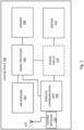
- FIG. 1 A block-diagram of a typical hearing device 100 is shown in Fig. 1 .
- the hearing device 100 comprises a first transducer, i.e. microphone 102, for receiving incoming sound and converting it into an audio signal, i.e. a first audio signal.
- the first audio signal is provided to a signal processor 104 for processing the first audio signal into a second audio signal compensating a hearing loss of a user of the hearing device 100.
- a receiver or speaker 106 is connected to an output of the signal processor 104 for converting the second audio signal into an output sound signal, e.g. a signal modified to compensate for a user's hearing impairment, and provides the output sound to the speaker 106.
- the hearing device signal processor 104 comprises elements such as amplifiers, compressors and noise reduction systems etc.
- the hearing device may further have a filter function, such as compensation filter for optimizing the output signal.
- the hearing device may furthermore have a wireless communication unit 108, such as a wireless communication circuit, for wireless data communication interconnected with an antenna 210 for emission and reception of an electromagnetic field.
- the wireless communication unit 108 including a radio or a transceiver, connect to the hearing device signal processor 104 and the antenna 210, for communicating with external devices, or with another hearing device, such as another hearing device, located at another ear, typically in a binaural hearing device system.
- the hearing device 100 further comprises a power source 112, such as a battery.
- a power circuit 110 (optional) is provided for controlling the power provided from the battery 112 to the signal processor 104 and the wireless communication unit 108.
- a feeding network 109 is providing a feed for the antenna 210.
- the hearing device is an in-the-ear hearing device comprising a hearing device shell 200 and a faceplate 204.
- the shell is hollow.
- the hearing device shell is provided with an open end through which electronic hearing components are fitted into the hearing device shell 200. The open end of the shell is afterwards closed by a faceplate 204.
- the faceplate may be fastened to the hearing device shell in any known way, e.g. by gluing, molding, press-fitting, etc.
- the faceplate 204 is configured with battery door to provide access to a battery of the hearing device.
- the electronic hearing components includes for example the microphone 102, the signal processor 104, the speaker 106, the wireless communication unit 108 and the feeding network 109.
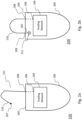
- Figs. 2a-2d schematically illustrates exemplary antennas of a hearing device.
- the hearing device illustrated is an in-the-ear hearing device 100 having a hearing device shell 200 and a faceplate 204.
- the antenna 210 extends through the faceplate 204 at a first position 208 of the faceplate.
- the antenna 210 has a first end 206 being fed from the feeding network 109 at feed 205.
- the antenna 210 extends from the faceplate 204 from first position 208 and the part of the antenna extending from the faceplate is marked with reference number 211. At least a part of the antenna extending from the faceplate 204 is arch-shaped and the second end 207 of the antenna 210 is an electrically open end.
- the antenna 210 extends from the faceplate 204 from first position 208 and the part of the antenna extending from the faceplate is marked with reference number 211.
- the antenna 210 extends in a looped shape from the first position 208 of the faceplate to a second position 209 of the face plate, the antenna 210 has an interconnection to the faceplate 204 at the second position 209.
- the second end 207 of the antenna 210 is interconnected to a ground potential 212.
- the second end 207 of the antenna 210 may be interconnected to the ground potential 212 through a controlled impedance (not shown).
- the ground potential 212 may be provided in the faceplate 204, so that the second end 207 of the antenna is not extending through the faceplate 204.
- the ground potential 212 is provided in the hearing device shell 200, i.e. on the inside of the faceplate, and the antenna extends through the faceplate 204 at the second position 209 to connect with the ground potential 212.
- the antenna 210 extends from the feed 205 through the faceplate 204 at first position 208 to the second end 207 of the antenna; at least the part of the antenna extending from the faceplate 204 has a rod shape; the second end 207 being an open end, i.e. an electrically open end.
- the antenna extends from the feed 205 at the first end 206 of the antenna and the antenna extends through the faceplate 204 at the first position 208.
- the antenna forms a loop and interconnects with the faceplate at the second position 209.
- a pull-out handle 216 is shown.
- the antenna 210 extends within the pull-out handle 216.
- the pull-out handle 216 is a hollow tube, and e.g. made of nylon, and the antenna extends within the tube.
- the pull-out handle may be made in any other way, and the antenna may extend within a hollow tubular pull-out handle, the antenna may be embedded within the material of the pull-out handle, etc.
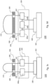
- Figs. 3a-d schematically illustrates exemplary feeding networks for exemplary antennas.
- the electronic hearing components including for example the microphone 102, the signal processor 104, the speaker 106, the wireless communication unit 108 and/or the feeding network 109 are provided in the hearing device shell (not shown in Figs. 3a-d ).
- the antenna illustrated in Fig. 3a corresponds to the antenna illustrated in Fig. 2a .
- the antenna 210 extends from the feed 205 through the faceplate 204 to the second end 207; the second end being an open end.
- the faceplate 204 has a through-hole 308 through which the antenna 210 extends.
- the antenna may be provided with any coating or cover (not shown) to make the antenna more robust and the antenna may be connected to the faceplate in any manner.
- the feeding network 109 is shown in more detail.
- the antenna is fed from the feeding network, and the feeding network provides an interconnection between the antenna and the wireless communication unit.
- the interconnection is provided at the first end 206 of the antenna and/or at the second end 207 of the antenna.
- the interconnection between the antenna and the wireless communication unit is provided through one or more controlled impedances, the controlled impedances including capacitors, inductors and/or transmission lines.
- the controlled impedances are selected to design the RF current distribution of the antenna.
- the controlled impedances are configured to optimize antenna parameters, including antenna impedance matching.
- the wireless communication unit 108 is provided at printed circuit board 302.
- the printed circuit board 302 forms the ground plane for the antenna 210.
- the faceplate 204 is shown in more detail.
- the faceplate has one or more through-holes, including first through-hole 308 and possibly second through-hole 309.
- the antenna 210 extends from the feed 205 through the first through-hole 308 at the first position 208 of the faceplate 204.
- the antenna extends through the faceplate 204 at the second position 209 through second through-hole 309.
- the second end 207 of the antenna may then connect to the feeding network 109 within the hearing device shell 200.
- the second end 207 of the antenna is connected to the faceplate 204 with or without extending through the faceplate.
- the wireless communication unit 108 being positioned on a printed circuit board 302, is connected to a first controlled impedance 306a, the first controlled impedance is connected to a second controlled impedance 306b and further has a connection to ground potential 212.
- the first end 206 of the antenna is connected to the second controlled impedance 306b at 205 providing a feed for the antenna.
- the feed in Fig. 3a is a single ended feed.
- the feeding network represents an inverted F-antenna.
- the second end 207 of the antenna is an open end.
- the wireless communication unit is connected to the antenna through controlled impedance 306a.
- the antenna 210 is connected to the controlled impedance at the first end 206 at position 205 providing a feed for the antenna.
- the feeding network provides a monopole antenna.
- the second end 207 of the antenna is interconnected with the faceplate. It is an advantage of interconnecting the second end 207 of the antenna with the faceplate in that noise stemming from handling of the antenna or the pull-out handle comprising the antenna may be reduced.
- the second end 207 of the antenna may be connected to a ground potential (not shown).
- the antenna 210 is interconnected with wireless communication unit 108 through feeding network 109.
- the first end 206 of the antenna 210 connects to the wireless communication unit 108 through controllable impedance 306a.
- the second end 207 of the antenna 210 connects to the wireless communication unit 108 through controllable impedance 306b.
- the antenna 210 forms a loop antenna with both the first end 206 and the second end 207 being interconnected with the wireless communication unit 108.
- the antenna 210 is interconnected with wireless communication unit 108 through feeding network 109.
- the first end 206 of the antenna connects to the wireless communication unit 108 through controllable impedance 306a.
- the second end 207 of the antenna connects to the wireless communication unit 108 through controllable impedance 306b.
- the antenna 210 forms a loop antenna with both the first end 206 and the second end 207 being interconnected with the wireless communication unit 108.
- a further controlled impedance 306c is provided between the first and second controlled impedances, 306a, 306b.
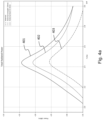
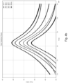
- Fig. 4a total radiated power for an antenna of an embodiment of the disclosure is shown.
- the graph shows three different antenna configurations, internal antenna, external antenna being a straight wire having a length of 10 mm, and an external bent antenna, i.e. being arch-shaped having a length of 6.4 mm.
- the total radiated power (dBm) is measured over a frequency range of 2.0 GHz to 3.0 GHz.
- the measured total radiated power for the internal antenna is illustrated by curve 403
- the total radiated power for the straight wire antenna is illustrated by curve 402
- the total radiated power for the bent wire antenna is illustrated by curve 401. It is seen that the bent wire antenna, even thought the total length is smaller than for the straight wire antenna, provides the highest total radiated power. This is a significant advantage and indicates that contrary to normal beliefs, a long straight wire antenna is not the optimum choice.
- Fig. 4b shows total radiated power for a straight wire antenna having different lengths above the faceplate measured as for Fig. 4a . It is seen that the longer the wire is the more radiated power may be provided, and that only with a length of 10 mm above the faceplate is the total radiated power above -20 dBm.
- Fig 5 shows a top view of a faceplate 204.
- the faceplate is presented as elliptical, however, it is envisaged that the faceplate may have any shape, including circular, elliptical, or any shape corresponding to the shape of the ear, when the hearing device is configured to extend into the concha of an ear.
- the first position 208 and the second position 209 are illustrated.
- the location of the first position and the second position at the faceplate are associated with the arrangement of the faceplate in the ear of a user.
- the faceplate comprising the first position 208 and the second position 209 has an orientation so that the first position 208 is located towards a front end 502, the front end 502 being closer to the tragus of an ear of a user when the hearing device is positioned at the operational position in the ear of the user, than a back end of the faceplate.
- the faceplate has an orientation so that the first position 208 is located towards the tragus/front of the head/ear, i.e.
- the first end 206 of the antenna is located closer to the tragus of the ear of a user than the second end 207 of the antenna when the hearing device is positioned at the operational position in the ear of a user.
- intersection 506 is illustrated, the intersection 506 dividing the faceplate in a front end and a back end, typically along a center axis for the faceplate 204.
- Fig. 6 illustrates the sizes of the antenna.
- the antenna 210 forms a loop, and the antenna 210 extends above the faceplate 204 from the first position 208 to the second position 209.
- a first section 604 of the antenna extends from the first position 208 along a first axis 601, the first axis forming a first angle with an ear-to-ear axis of a user when the hearing device is positioned in the operational position in the ear of a user, the first angle being less than 25°.
- the antenna has a second section 606 extending along a second axis 602, the second axis forming a second angle with the faceplate, the second angle being less than 25°.
- the antenna 210 further has a third section 608 extending parallel to the first axis and being interconnected with the faceplate 204 at the second position 209 of the faceplate.
- the distance d1 between the first position 208 and the second position 209 is typically less than 10 mm, such as between 3 and 8 mm, such as 4 mm.
- the distance d2 from the faceplate 204 to a part of the antenna is between 2 mm and 2 cm, such as between 5 mm and 15 mm above the faceplate, such as 8 mm above the faceplate.
- the distance d2 may be measured between the faceplate and at least one point of the antenna 210, and at least one point is a highest point.
- Fig. 7a illustrates an example of a hearing device having an antenna 210, wherein the wireless communication unit 108, the feeding network 109 and the microphone 102 are positioned at a printed circuit board 302 inside the hearing device shell 200.
- a transmission line 701 interconnects the wireless communication unit 108 with the feeding network 109.
- the antenna 210 is fed from the feeding network 109 and the interior part 702 of the antenna 210 extends within the hearing device shell 200, through through-hole 308 in the faceplate 204 and the exterior part 211 of the antenna 210 extends above the faceplate, i.e. above the outer side of the faceplate.
- Fig. 7b illustrates an example of a hearing device having an antenna 210, wherein the wireless communication unit 108, the feeding network 109 and the signal processor 104 are positioned at a printed circuit board 302 inside the hearing device shell 200.
- the microphone 102 are provided outside of the hearing device shell 200.
- the microphone 102 may for example be configured to be provided in the helix of the ear of the user.
- the hearing device may be of the microphone-in-the helix type.
- a transmission line 701 interconnects the wireless communication unit 108 with the feeding network 109.
- the antenna 210 is fed from the feeding network 109 and the interior part 702 of the antenna 210 extends within the hearing device shell 200, through through-hole 308 in the faceplate 204 and the exterior part 211 of the antenna 210 extends above the faceplate, i.e. above the outer side of the faceplate.
- the one or more microphones are interconnected with the signal processor 104 via signal line 704 including one or more conducting wires.
- the signal line 704 and the antenna 210 may be provided in a same tube.
- the signal line 704 may function also as the antenna 210. Thus, by re-using the signal line to function also as antenna 210, a separate conducting element functioning as antenna may be avoided.
- the signal line 704 may comprise the antenna 210, more specifically, the signal line 704 may comprises the exterior part 211 of the antenna, or the signal line 704 may comprise the interior part 702 of the antenna and the exterior part 211 of the antenna.
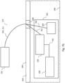
- Figs. 8a - 8c illustrates a hearing device having electric components positioned in modules.
- the modular positioning of electric components within the hearing device enables a better noise control, as connecting wires etc. may be positioned between the modules in a controlled way.
- the hearing device comprises antenna 802, battery 804 and battery springs 808.
- the hybrid 806, comprises a number of electric components (not specified), the receiver or speaker 818 is provided extending from hybrid 806.
- the receiver 818 is provided in a support, the support supporting both the hybrid 806 and the receiver 818.
- Microphones 801 are provided adjacent a faceplate 807. As seen a lid may be provided on top of the faceplate 807. Battery contact points 810a, 810b are provided for feeding power to the electric components.
- Antenna feed 812 is shown, and the second end connection 814 of the antenna 802 is connected to the hybrid 806 via printed circuit board 816.
- Fig. 8c shows a third perspective of the hearing device.
- the antenna 802 is shown extending from faceplate 807.
- Receiver module 818 is seen below hybrid 806.
- the battery springs/connectors 808 are also shown. It is seen that the modular build provides a compact hearing device in which position of components may be well controlled.
Landscapes
- Engineering & Computer Science (AREA)
- Signal Processing (AREA)
- Acoustics & Sound (AREA)
- General Health & Medical Sciences (AREA)
- Neurosurgery (AREA)
- Otolaryngology (AREA)
- Physics & Mathematics (AREA)
- Health & Medical Sciences (AREA)
- Computer Networks & Wireless Communication (AREA)
- Manufacturing & Machinery (AREA)
- Support Of Aerials (AREA)
- Details Of Aerials (AREA)
- Details Of Audible-Bandwidth Transducers (AREA)
- Transceivers (AREA)
- Transmitters (AREA)
- Headphones And Earphones (AREA)
Claims (13)
- Ein Im-Ohr-Hörgerät (100) miteine Hörgeräteschale (200) umfassendein Mikrofon (102), das zum Empfangen eines Audiosignals konfiguriert ist,einen Signalprozessor (104), der dazu konfiguriert ist, das Audiosignal zu verarbeiten, um einen Hörverlust eines Benutzers auszugleichen,eine drahtlose Kommunikationseinheit (108), wobei die drahtlose Kommunikationseinheit (108) mit dem Signalprozessor (104) verbunden ist, undein Speisenetz (109),wobei das Hörgerät weiterhin umfasst:eine an der Hörgeräteschale (200) angeordnete Frontplatte (204) undeine Antenne (210) zum Aussenden und Empfangen eines elektromagnetischen Felds, die mit der drahtlosen Kommunikationseinheit (108) verbunden ist,wobei die Antenne (210) ein erstes Ende (206) aufweist, das aus dem Speisenetz (109) gespeist wird,wobei sich die Antenne (210) an einer ersten Position (208) der Frontplatte (204) durch die Frontplatte (204 ) erstreckt;wobei zumindest ein Teil der Antenne (210), der von der Frontplatte (204) ausgeht, bogenförmig ist undwobei ein zweites Ende (207) der Antenne (210) an einer zweiten Position (209) der Frontplatte (204) mit der Frontplatte (204) verbunden ist,wobei die Frontplatte, die die erste Position (208) und die zweite Position (209) umfasst, eine Ausrichtung aufweist, so dass die erste Position in Richtung eines vorderen Endes (502) angeordnet ist, wobei das vordere Ende näher am Tragus eines Ohrs eines Benutzers ist, wenn das Hörgerät in der Betriebsposition im Ohr des Benutzers positioniert ist, als ein hinteres Ende (504) der Frontplatte (204),wobei das erste Ende der Antenne näher am Tragus des Ohrs des Benutzers liegt als das zweite Ende der Antenne, wenn sich das Hörgerät in der Betriebsposition im Ohr eines Benutzers befindet, undwobei das zweite Ende (207) der Antenne ein elektrisch offenes Ende ist, oderwobei das zweite Ende (207) der Antenne (210) mit einem Erdpotential (212) verbunden ist.
- Hörgerät (100) nach Anspruch 1, wobei sich ein erster Abschnitt (604) der Antenne (210) von der ersten Position (208) entlang einer ersten Achse (601) erstreckt, wobei die erste Achse einen ersten Winkel mit einer Ohr-zu-Ohr-Achse eines Benutzers bildet, wenn das Hörgerät in der Betriebsposition im Ohr eines Benutzers positioniert ist, wobei der erste Winkel kleiner als 25° ist.wobei die Antenne einen zweiten Abschnitt (606) aufweist, der sich entlang einer zweiten Achse (602) erstreckt, wobei die zweite Achse einen zweiten Winkel mit der Frontplatte (204) bildet, wobei der zweite Winkel kleiner als 25° ist, undwobei die Antenne außerdem einen dritten Abschnitt (608) aufweist, der parallel zur ersten Achse (601) verläuft und an der zweiten Position (209) der Frontplatte mit der Frontplatte (204) verbunden ist.
- Hörgerät (100) nach Anspruch 2, wobei der zweite Abschnitt (606) der Antenne (210) bogenförmig ist.
- Hörgerät (100) nach einem der vorhergehenden Ansprüche, wobei das Antennenspeisenetzwerk (109) so konfiguriert ist, dass es eine unsymmetrische Speisung oder eine differenzielle Speisung bereitstellt.
- Hörgerät (100) nach einem der vorhergehenden Ansprüche, wobei sich das Speisenetzwerk (109) neben der Frontplatte befindet.
- Hörgerät (100) nach einem der vorhergehenden Ansprüche, wobei die Länge der Antenne (210) ein Viertel einer Wellenlänge der vom Hörgerät auszusendenden elektromagnetischen Strahlung beträgt.
- Hörgerät (100) nach einem der vorhergehenden Ansprüche, wobei die Antenne (210) einen Teil eines Ausziehgriffs bildet und wobei der Ausziehgriff an der Frontplatte verankert ist.
- Hörgerät (100) nach einem der Ansprüche 3-7, wobei ein Strom in der Antenne (210) in der Nähe des ersten Abschnitts der Antenne (210) ein Maximum aufweist.
- Hörgerät (100) nach einem der vorhergehenden Ansprüche, wobei die Antenne eine elektrische Monopolantenne ist.
- Hörgerät (100) nach einem der vorhergehenden Ansprüche, wobei die drahtlose Kommunikationseinheit auf einer Leiterplatte platziert ist, die die Massefläche (304) der Antenne (210) bildet.
- Hörgerät (100) nach einem der Ansprüche 1-9, wobei ein erstes Modul die drahtlose Kommunikationseinheit, den Signalprozessor und eine Leiterplatte umfasst, wobei die drahtlose Kommunikationseinheit und der Signalprozessor auf der Leiterplatte im Hörgerätegehäuse vorgesehen sind, und wobei ein zweites Modul das Mikrofon umfasst und im Hörgerätegehäuse neben der Frontplatte positioniert ist, und wobei mindestens ein Verbindungskabel, das das Mikrofon im zweiten Modul und den Signalprozessor des ersten Moduls verbindet, mindestens einen Teil der Antenne (210) bildet.
- Hörgerät (100) nach Anspruch 1, wobei ein erster Teil der Antenne (210), der sich von der Frontplatte erstreckt, eine U-Form, eine Kreisform oder eine elliptische Form hat.
- Hörgerät (100) nach einem der vorhergehenden Ansprüche, wobei das Speisenetzwerk (109) eine oder mehrere gesteuerte Impedanzen (306a, 306b, 306c) umfasst, darunter Kondensatoren, Induktoren und/oder Übertragungsleitungen, die dazu konfiguriert sind, Antennenparameter, darunter die Antennenimpedanzanpassung, zu optimieren.
Priority Applications (5)
| Application Number | Priority Date | Filing Date | Title |
|---|---|---|---|
| EP18197790.1A EP3629600B1 (de) | 2018-09-28 | 2018-09-28 | Hörgerät mit einer von dem hörgerät ausgehenden antenne |
| EP24174307.9A EP4387275A3 (de) | 2018-09-28 | 2018-09-28 | Hörgerät mit einer von dem hörgerät ausgehenden antenne |
| US16/544,040 US11496843B2 (en) | 2018-09-28 | 2019-08-19 | Hearing device with antenna extending from the hearing device |
| JP2019175980A JP2020078054A (ja) | 2018-09-28 | 2019-09-26 | 聴覚デバイスから延在しているアンテナを備える聴覚デバイス |
| CN201910929862.5A CN110972050B (zh) | 2018-09-28 | 2019-09-27 | 具有从听力设备延伸的天线的听力设备 |
Applications Claiming Priority (1)
| Application Number | Priority Date | Filing Date | Title |
|---|---|---|---|
| EP18197790.1A EP3629600B1 (de) | 2018-09-28 | 2018-09-28 | Hörgerät mit einer von dem hörgerät ausgehenden antenne |
Related Child Applications (2)
| Application Number | Title | Priority Date | Filing Date |
|---|---|---|---|
| EP24174307.9A Division EP4387275A3 (de) | 2018-09-28 | 2018-09-28 | Hörgerät mit einer von dem hörgerät ausgehenden antenne |
| EP24174307.9A Division-Into EP4387275A3 (de) | 2018-09-28 | 2018-09-28 | Hörgerät mit einer von dem hörgerät ausgehenden antenne |
Publications (3)
| Publication Number | Publication Date |
|---|---|
| EP3629600A1 EP3629600A1 (de) | 2020-04-01 |
| EP3629600C0 EP3629600C0 (de) | 2024-10-23 |
| EP3629600B1 true EP3629600B1 (de) | 2024-10-23 |
Family
ID=63713745
Family Applications (2)
| Application Number | Title | Priority Date | Filing Date |
|---|---|---|---|
| EP24174307.9A Pending EP4387275A3 (de) | 2018-09-28 | 2018-09-28 | Hörgerät mit einer von dem hörgerät ausgehenden antenne |
| EP18197790.1A Active EP3629600B1 (de) | 2018-09-28 | 2018-09-28 | Hörgerät mit einer von dem hörgerät ausgehenden antenne |
Family Applications Before (1)
| Application Number | Title | Priority Date | Filing Date |
|---|---|---|---|
| EP24174307.9A Pending EP4387275A3 (de) | 2018-09-28 | 2018-09-28 | Hörgerät mit einer von dem hörgerät ausgehenden antenne |
Country Status (4)
| Country | Link |
|---|---|
| US (1) | US11496843B2 (de) |
| EP (2) | EP4387275A3 (de) |
| JP (1) | JP2020078054A (de) |
| CN (1) | CN110972050B (de) |
Families Citing this family (11)
| Publication number | Priority date | Publication date | Assignee | Title |
|---|---|---|---|---|
| DK3629599T3 (da) * | 2018-09-28 | 2022-01-10 | Gn Hearing As | Høreapparat, der omfatter en sløjfeantenne |
| US11654943B2 (en) * | 2018-10-18 | 2023-05-23 | Westinghouse Air Brake Technologies Corporation | End of vehicle device with integrated antenna |
| US12330698B2 (en) | 2018-10-18 | 2025-06-17 | Transportation Ip Holdings, Llc | End of train device with integrated antenna |
| US11026027B2 (en) | 2019-05-10 | 2021-06-01 | Starkey Laboratories, Inc. | Ear-worn electronic device incorporating an antenna actively loaded using a non-foster circuit |
| EP4038903A1 (de) | 2019-10-01 | 2022-08-10 | Starkey Laboratories, Inc. | Antennendesigns für hörgeräte |
| DE102020201480A1 (de) * | 2020-02-06 | 2021-08-12 | Sivantos Pte. Ltd. | Hörgerät |
| DE102020201479A1 (de) * | 2020-02-06 | 2021-08-12 | Sivantos Pte. Ltd. | Hörgerät |
| EP4272460B1 (de) | 2021-01-04 | 2026-03-11 | Starkey Laboratories, Inc. | Hörgerät mit einem haltemechanismus für ein externes multifunktionskabel und verfahren zur montage des genannten hörgeräts. |
| WO2022173628A1 (en) * | 2021-02-10 | 2022-08-18 | Starkey Laboratories, Inc. | Antenna designs for hearing instruments |
| WO2025171872A1 (de) | 2024-02-15 | 2025-08-21 | Sivantos Pte. Ltd. | In-dem-ohr hörgerät |
| EP4615008A1 (de) * | 2024-03-04 | 2025-09-10 | Oticon A/s | Hörgerät |
Citations (2)
| Publication number | Priority date | Publication date | Assignee | Title |
|---|---|---|---|---|
| US20100020994A1 (en) * | 2004-10-28 | 2010-01-28 | Christensen Craig L | Antenna integrated with retrieval component of hearing aid |
| WO2018024377A1 (de) * | 2016-08-01 | 2018-02-08 | Sivantos Pte. Ltd. | Hörhilfegerät und hörhilfevorrichtung |
Family Cites Families (12)
| Publication number | Priority date | Publication date | Assignee | Title |
|---|---|---|---|---|
| US6055319A (en) * | 1997-11-06 | 2000-04-25 | Decibel Instruments, Inc. | Selectable handle for hearing devices |
| EP2087778A4 (de) * | 2006-08-22 | 2010-11-17 | Mattson Tech Inc | Induktive plasmaquelle mit hohem koppelwirkungsgrad |
| US8867765B2 (en) * | 2008-02-06 | 2014-10-21 | Starkey Laboratories, Inc. | Antenna used in conjunction with the conductors for an audio transducer |
| EP2393308B1 (de) * | 2010-06-07 | 2019-10-16 | Oticon A/s | Hörgerät mit einem gefalteten Substrat |
| EP3110174B1 (de) * | 2015-06-24 | 2021-02-17 | Oticon A/s | Hörgerät mit antenneneinheit und abgeschirmter übertragungsleitung |
| DK3116238T3 (da) | 2015-07-08 | 2020-03-23 | Oticon As | Afstandsstykke og høreanordning, som omfatter det |
| US9609443B2 (en) * | 2015-07-21 | 2017-03-28 | Gn Hearing A/S | In-the-ear hearing aid having combined antennas |
| US9949014B2 (en) * | 2016-06-13 | 2018-04-17 | Peag, LLC | Wireless pair of earbuds |
| WO2018024392A1 (de) * | 2016-08-01 | 2018-02-08 | Sivantos Pte. Ltd. | Hörgerät mit rf-antenne |
| US10051388B2 (en) * | 2016-09-21 | 2018-08-14 | Starkey Laboratories, Inc. | Radio frequency antenna for an in-the-ear hearing device |
| US11432079B2 (en) * | 2018-09-05 | 2022-08-30 | Oticon A/S | Hearing aid with automatic antenna tuning |
| DK3629599T3 (da) * | 2018-09-28 | 2022-01-10 | Gn Hearing As | Høreapparat, der omfatter en sløjfeantenne |
-
2018
- 2018-09-28 EP EP24174307.9A patent/EP4387275A3/de active Pending
- 2018-09-28 EP EP18197790.1A patent/EP3629600B1/de active Active
-
2019
- 2019-08-19 US US16/544,040 patent/US11496843B2/en active Active
- 2019-09-26 JP JP2019175980A patent/JP2020078054A/ja active Pending
- 2019-09-27 CN CN201910929862.5A patent/CN110972050B/zh active Active
Patent Citations (2)
| Publication number | Priority date | Publication date | Assignee | Title |
|---|---|---|---|---|
| US20100020994A1 (en) * | 2004-10-28 | 2010-01-28 | Christensen Craig L | Antenna integrated with retrieval component of hearing aid |
| WO2018024377A1 (de) * | 2016-08-01 | 2018-02-08 | Sivantos Pte. Ltd. | Hörhilfegerät und hörhilfevorrichtung |
Non-Patent Citations (1)
| Title |
|---|
| ANONYMOUS: "Arch - Wikipedia", 27 September 2018 (2018-09-27), XP093081416, Retrieved from the Internet <URL:https://en.wikipedia.org/w/index.php?title=Arch&oldid=861511315> [retrieved on 20230912] * |
Also Published As
| Publication number | Publication date |
|---|---|
| EP3629600A1 (de) | 2020-04-01 |
| EP3629600C0 (de) | 2024-10-23 |
| EP4387275A2 (de) | 2024-06-19 |
| CN110972050A (zh) | 2020-04-07 |
| US11496843B2 (en) | 2022-11-08 |
| JP2020078054A (ja) | 2020-05-21 |
| EP4387275A3 (de) | 2024-08-07 |
| CN110972050B (zh) | 2023-05-30 |
| US20200107141A1 (en) | 2020-04-02 |
Similar Documents
| Publication | Publication Date | Title |
|---|---|---|
| EP3629600B1 (de) | Hörgerät mit einer von dem hörgerät ausgehenden antenne | |
| US10667064B2 (en) | ITE hearing aid with improved wireless communication | |
| US10667065B2 (en) | Hearing instrument having an antenna system | |
| WO2016207215A1 (en) | A hearing aid having combined antennas | |
| US9877119B2 (en) | Hearing aid with antenna on printed circuit board | |
| US11792582B2 (en) | Multiple arm dipole antenna for hearing instrument | |
| US11290828B2 (en) | Hearing device with antenna functionality in supporting structure | |
| US11432080B2 (en) | Hearing device with integrated magnetic induction coil and RF antenna | |
| EP3174314B1 (de) | In-ohr-hörgerät mit verbesserter drahtloskommunikation | |
| EP3185583B1 (de) | Hörgerät mit antenne auf einer leiterplatte | |
| EP3503589B1 (de) | Hörgerät mit kombinierten antennen | |
| DK201570757A1 (en) | Ite hearing aid with improved wireless communication | |
| DK201570841A1 (en) | Hearing aid with antenna on printed circuit board |
Legal Events
| Date | Code | Title | Description |
|---|---|---|---|
| PUAI | Public reference made under article 153(3) epc to a published international application that has entered the european phase |
Free format text: ORIGINAL CODE: 0009012 |
|
| STAA | Information on the status of an ep patent application or granted ep patent |
Free format text: STATUS: THE APPLICATION HAS BEEN PUBLISHED |
|
| AK | Designated contracting states |
Kind code of ref document: A1 Designated state(s): AL AT BE BG CH CY CZ DE DK EE ES FI FR GB GR HR HU IE IS IT LI LT LU LV MC MK MT NL NO PL PT RO RS SE SI SK SM TR |
|
| AX | Request for extension of the european patent |
Extension state: BA ME |
|
| STAA | Information on the status of an ep patent application or granted ep patent |
Free format text: STATUS: REQUEST FOR EXAMINATION WAS MADE |
|
| 17P | Request for examination filed |
Effective date: 20201001 |
|
| RBV | Designated contracting states (corrected) |
Designated state(s): AL AT BE BG CH CY CZ DE DK EE ES FI FR GB GR HR HU IE IS IT LI LT LU LV MC MK MT NL NO PL PT RO RS SE SI SK SM TR |
|
| STAA | Information on the status of an ep patent application or granted ep patent |
Free format text: STATUS: EXAMINATION IS IN PROGRESS |
|
| 17Q | First examination report despatched |
Effective date: 20211020 |
|
| GRAP | Despatch of communication of intention to grant a patent |
Free format text: ORIGINAL CODE: EPIDOSNIGR1 |
|
| STAA | Information on the status of an ep patent application or granted ep patent |
Free format text: STATUS: GRANT OF PATENT IS INTENDED |
|
| INTG | Intention to grant announced |
Effective date: 20240524 |
|
| GRAS | Grant fee paid |
Free format text: ORIGINAL CODE: EPIDOSNIGR3 |
|
| GRAA | (expected) grant |
Free format text: ORIGINAL CODE: 0009210 |
|
| STAA | Information on the status of an ep patent application or granted ep patent |
Free format text: STATUS: THE PATENT HAS BEEN GRANTED |
|
| AK | Designated contracting states |
Kind code of ref document: B1 Designated state(s): AL AT BE BG CH CY CZ DE DK EE ES FI FR GB GR HR HU IE IS IT LI LT LU LV MC MK MT NL NO PL PT RO RS SE SI SK SM TR |
|
| REG | Reference to a national code |
Ref country code: GB Ref legal event code: FG4D |
|
| REG | Reference to a national code |
Ref country code: CH Ref legal event code: EP |
|
| REG | Reference to a national code |
Ref country code: DE Ref legal event code: R096 Ref document number: 602018075683 Country of ref document: DE |
|
| REG | Reference to a national code |
Ref country code: IE Ref legal event code: FG4D |
|
| U01 | Request for unitary effect filed |
Effective date: 20241121 |
|
| U07 | Unitary effect registered |
Designated state(s): AT BE BG DE DK EE FI FR IT LT LU LV MT NL PT RO SE SI Effective date: 20241127 |
|
| PG25 | Lapsed in a contracting state [announced via postgrant information from national office to epo] |
Ref country code: HR Free format text: LAPSE BECAUSE OF FAILURE TO SUBMIT A TRANSLATION OF THE DESCRIPTION OR TO PAY THE FEE WITHIN THE PRESCRIBED TIME-LIMIT Effective date: 20241023 Ref country code: IS Free format text: LAPSE BECAUSE OF FAILURE TO SUBMIT A TRANSLATION OF THE DESCRIPTION OR TO PAY THE FEE WITHIN THE PRESCRIBED TIME-LIMIT Effective date: 20250223 |
|
| PG25 | Lapsed in a contracting state [announced via postgrant information from national office to epo] |
Ref country code: ES Free format text: LAPSE BECAUSE OF FAILURE TO SUBMIT A TRANSLATION OF THE DESCRIPTION OR TO PAY THE FEE WITHIN THE PRESCRIBED TIME-LIMIT Effective date: 20241023 |
|
| PG25 | Lapsed in a contracting state [announced via postgrant information from national office to epo] |
Ref country code: NO Free format text: LAPSE BECAUSE OF FAILURE TO SUBMIT A TRANSLATION OF THE DESCRIPTION OR TO PAY THE FEE WITHIN THE PRESCRIBED TIME-LIMIT Effective date: 20250123 |
|
| PG25 | Lapsed in a contracting state [announced via postgrant information from national office to epo] |
Ref country code: GR Free format text: LAPSE BECAUSE OF FAILURE TO SUBMIT A TRANSLATION OF THE DESCRIPTION OR TO PAY THE FEE WITHIN THE PRESCRIBED TIME-LIMIT Effective date: 20250124 |
|
| PG25 | Lapsed in a contracting state [announced via postgrant information from national office to epo] |
Ref country code: PL Free format text: LAPSE BECAUSE OF FAILURE TO SUBMIT A TRANSLATION OF THE DESCRIPTION OR TO PAY THE FEE WITHIN THE PRESCRIBED TIME-LIMIT Effective date: 20241023 |
|
| PG25 | Lapsed in a contracting state [announced via postgrant information from national office to epo] |
Ref country code: RS Free format text: LAPSE BECAUSE OF FAILURE TO SUBMIT A TRANSLATION OF THE DESCRIPTION OR TO PAY THE FEE WITHIN THE PRESCRIBED TIME-LIMIT Effective date: 20250123 |
|
| PG25 | Lapsed in a contracting state [announced via postgrant information from national office to epo] |
Ref country code: SM Free format text: LAPSE BECAUSE OF FAILURE TO SUBMIT A TRANSLATION OF THE DESCRIPTION OR TO PAY THE FEE WITHIN THE PRESCRIBED TIME-LIMIT Effective date: 20241023 |
|
| PG25 | Lapsed in a contracting state [announced via postgrant information from national office to epo] |
Ref country code: SK Free format text: LAPSE BECAUSE OF FAILURE TO SUBMIT A TRANSLATION OF THE DESCRIPTION OR TO PAY THE FEE WITHIN THE PRESCRIBED TIME-LIMIT Effective date: 20241023 |
|
| PG25 | Lapsed in a contracting state [announced via postgrant information from national office to epo] |
Ref country code: CZ Free format text: LAPSE BECAUSE OF FAILURE TO SUBMIT A TRANSLATION OF THE DESCRIPTION OR TO PAY THE FEE WITHIN THE PRESCRIBED TIME-LIMIT Effective date: 20241023 |
|
| PLBE | No opposition filed within time limit |
Free format text: ORIGINAL CODE: 0009261 |
|
| STAA | Information on the status of an ep patent application or granted ep patent |
Free format text: STATUS: NO OPPOSITION FILED WITHIN TIME LIMIT |
|
| 26N | No opposition filed |
Effective date: 20250724 |
|
| REG | Reference to a national code |
Ref country code: CH Ref legal event code: U11 Free format text: ST27 STATUS EVENT CODE: U-0-0-U10-U11 (AS PROVIDED BY THE NATIONAL OFFICE) Effective date: 20251001 |
|
| PGFP | Annual fee paid to national office [announced via postgrant information from national office to epo] |
Ref country code: GB Payment date: 20250916 Year of fee payment: 8 |
|
| U20 | Renewal fee for the european patent with unitary effect paid |
Year of fee payment: 8 Effective date: 20250916 |
|
| PGFP | Annual fee paid to national office [announced via postgrant information from national office to epo] |
Ref country code: CH Payment date: 20251001 Year of fee payment: 8 |