EP3629590A2 - Microphone and terminal device - Google Patents
Microphone and terminal device Download PDFInfo
- Publication number
- EP3629590A2 EP3629590A2 EP19200142.8A EP19200142A EP3629590A2 EP 3629590 A2 EP3629590 A2 EP 3629590A2 EP 19200142 A EP19200142 A EP 19200142A EP 3629590 A2 EP3629590 A2 EP 3629590A2
- Authority
- EP
- European Patent Office
- Prior art keywords
- circuit board
- receiving hole
- sound receiving
- cavity
- adhesive member
- Prior art date
- Legal status (The legal status is an assumption and is not a legal conclusion. Google has not performed a legal analysis and makes no representation as to the accuracy of the status listed.)
- Withdrawn
Links
Images

Classifications
-
- H—ELECTRICITY
- H04—ELECTRIC COMMUNICATION TECHNIQUE
- H04R—LOUDSPEAKERS, MICROPHONES, GRAMOPHONE PICK-UPS OR LIKE ACOUSTIC ELECTROMECHANICAL TRANSDUCERS; ELECTRIC HEARING AIDS; PUBLIC ADDRESS SYSTEMS
- H04R7/00—Diaphragms for electromechanical transducers; Cones
- H04R7/02—Diaphragms for electromechanical transducers; Cones characterised by the construction
-
- H—ELECTRICITY
- H04—ELECTRIC COMMUNICATION TECHNIQUE
- H04R—LOUDSPEAKERS, MICROPHONES, GRAMOPHONE PICK-UPS OR LIKE ACOUSTIC ELECTROMECHANICAL TRANSDUCERS; ELECTRIC HEARING AIDS; PUBLIC ADDRESS SYSTEMS
- H04R1/00—Details of transducers, loudspeakers or microphones
- H04R1/08—Mouthpieces; Microphones; Attachments therefor
- H04R1/083—Special constructions of mouthpieces
- H04R1/086—Protective screens, e.g. all weather or wind screens
-
- H—ELECTRICITY
- H04—ELECTRIC COMMUNICATION TECHNIQUE
- H04R—LOUDSPEAKERS, MICROPHONES, GRAMOPHONE PICK-UPS OR LIKE ACOUSTIC ELECTROMECHANICAL TRANSDUCERS; ELECTRIC HEARING AIDS; PUBLIC ADDRESS SYSTEMS
- H04R1/00—Details of transducers, loudspeakers or microphones
- H04R1/02—Casings; Cabinets ; Supports therefor; Mountings therein
- H04R1/04—Structural association of microphone with electric circuitry therefor
-
- B—PERFORMING OPERATIONS; TRANSPORTING
- B81—MICROSTRUCTURAL TECHNOLOGY
- B81B—MICROSTRUCTURAL DEVICES OR SYSTEMS, e.g. MICROMECHANICAL DEVICES
- B81B7/00—Microstructural systems ; Auxiliary parts of microstructural devices or systems
- B81B7/0032—Packages or encapsulation
- B81B7/0035—Packages or encapsulation for maintaining a controlled atmosphere inside of the chamber containing the MEMS
- B81B7/0038—Packages or encapsulation for maintaining a controlled atmosphere inside of the chamber containing the MEMS using materials for controlling the level of pressure, contaminants or moisture inside of the package, e.g. getters
-
- H—ELECTRICITY
- H04—ELECTRIC COMMUNICATION TECHNIQUE
- H04R—LOUDSPEAKERS, MICROPHONES, GRAMOPHONE PICK-UPS OR LIKE ACOUSTIC ELECTROMECHANICAL TRANSDUCERS; ELECTRIC HEARING AIDS; PUBLIC ADDRESS SYSTEMS
- H04R1/00—Details of transducers, loudspeakers or microphones
- H04R1/20—Arrangements for obtaining desired frequency or directional characteristics
- H04R1/22—Arrangements for obtaining desired frequency or directional characteristics for obtaining desired frequency characteristic only
- H04R1/28—Transducer mountings or enclosures modified by provision of mechanical or acoustic impedances, e.g. resonator, damping means
- H04R1/2807—Enclosures comprising vibrating or resonating arrangements
-
- H—ELECTRICITY
- H04—ELECTRIC COMMUNICATION TECHNIQUE
- H04R—LOUDSPEAKERS, MICROPHONES, GRAMOPHONE PICK-UPS OR LIKE ACOUSTIC ELECTROMECHANICAL TRANSDUCERS; ELECTRIC HEARING AIDS; PUBLIC ADDRESS SYSTEMS
- H04R19/00—Electrostatic transducers
- H04R19/04—Microphones
-
- H—ELECTRICITY
- H04—ELECTRIC COMMUNICATION TECHNIQUE
- H04R—LOUDSPEAKERS, MICROPHONES, GRAMOPHONE PICK-UPS OR LIKE ACOUSTIC ELECTROMECHANICAL TRANSDUCERS; ELECTRIC HEARING AIDS; PUBLIC ADDRESS SYSTEMS
- H04R9/00—Transducers of moving-coil, moving-strip, or moving-wire type
- H04R9/06—Loudspeakers
-
- B—PERFORMING OPERATIONS; TRANSPORTING
- B81—MICROSTRUCTURAL TECHNOLOGY
- B81B—MICROSTRUCTURAL DEVICES OR SYSTEMS, e.g. MICROMECHANICAL DEVICES
- B81B2201/00—Specific applications of microelectromechanical systems
- B81B2201/02—Sensors
- B81B2201/0257—Microphones or microspeakers
-
- H—ELECTRICITY
- H04—ELECTRIC COMMUNICATION TECHNIQUE
- H04R—LOUDSPEAKERS, MICROPHONES, GRAMOPHONE PICK-UPS OR LIKE ACOUSTIC ELECTROMECHANICAL TRANSDUCERS; ELECTRIC HEARING AIDS; PUBLIC ADDRESS SYSTEMS
- H04R19/00—Electrostatic transducers
- H04R19/005—Electrostatic transducers using semiconductor materials
-
- H—ELECTRICITY
- H04—ELECTRIC COMMUNICATION TECHNIQUE
- H04R—LOUDSPEAKERS, MICROPHONES, GRAMOPHONE PICK-UPS OR LIKE ACOUSTIC ELECTROMECHANICAL TRANSDUCERS; ELECTRIC HEARING AIDS; PUBLIC ADDRESS SYSTEMS
- H04R2201/00—Details of transducers, loudspeakers or microphones covered by H04R1/00 but not provided for in any of its subgroups
- H04R2201/003—Mems transducers or their use
-
- H—ELECTRICITY
- H04—ELECTRIC COMMUNICATION TECHNIQUE
- H04R—LOUDSPEAKERS, MICROPHONES, GRAMOPHONE PICK-UPS OR LIKE ACOUSTIC ELECTROMECHANICAL TRANSDUCERS; ELECTRIC HEARING AIDS; PUBLIC ADDRESS SYSTEMS
- H04R7/00—Diaphragms for electromechanical transducers; Cones
- H04R7/02—Diaphragms for electromechanical transducers; Cones characterised by the construction
- H04R7/04—Plane diaphragms
- H04R7/045—Plane diaphragms using the distributed mode principle, i.e. whereby the acoustic radiation is emanated from uniformly distributed free bending wave vibration induced in a stiff panel and not from pistonic motion
Definitions
- the present disclosure relates to the field of terminal device technologies, and in particular, to a microphone and a terminal device.
- a microphone is an integral part of a terminal device.
- a microphone may include a signal converter and a circuit board.
- the signal converter may include a housing which forms a cavity, and a vibrating diaphragm located in the cavity; the sound receiving hole may be disposed on the circuit board.
- the signal converter may be connected to the circuit board so that the vibrating diaphragm is aligned with the sound receiving hole.
- a sound signal may be transmitted to the cavity through the sound receiving hole to drive the vibrating diaphragm to vibrate, thereby causing the signal converter to convert the sound signal into an electrical signal.
- impurities from outside the microphone may enter the cavity through the sound receiving hole and stay on the vibrating diaphragm. Accumulated impurities may scratch and pierce the vibrating diaphragm as the vibrating diaphragm vibrates, thereby affecting proper function of the microphone.
- the microphone includes a circuit board including a sound receiving hole; a signal converter configured to convert a sound signal into an electrical signal, wherein the signal converter includes a housing that forms a cavity, and wherein the cavity is connected to the sound receiving hole; and an adhesive member disposed in the cavity.
- the adhesive member is attached to a part of the circuit board that the cavity covers.
- the adhesive member extends from the cavity to the sound receiving hole.
- the adhesive member is at least partially attached to a sidewall of the sound receiving hole.
- the circuit board includes a supporting member attached to a sidewall of the sound receiving hole and located in the sound receiving hole, and the adhesive member is at least partially attached to the supporting member.
- the supporting member includes a supporting table extending towards an axis of the sound receiving hole, and the supporting table is configured to support the adhesive member.
- the microphone further includes a connecting layer including two adhesive surfaces disposed oppositely, wherein the two adhesive surfaces adhere to the adhesive member and a target carrier to which the adhesive member is to be attached, respectively.
- the circuit board includes a first flexible circuit board covering the cavity, and the sound receiving hole is disposed on the first flexible circuit board.
- the microphone further includes slits disposed around the sound receiving hole on the first flexible circuit board.
- the signal converter further includes an integrated circuit, and the integrated circuit is connected to the first flexible circuit board and disposed outside the cavity, and includes a component with a ring-shaped structure.
- the circuit board includes a second flexible circuit board located outside the cavity, and the second flexible circuit board includes staggered slits provided thereon.
- the staggered slits include arc-shaped ends.
- the adhesive member covers a free area on the circuit board.
- the supporting member is sleeved in the sound receiving hole.
- the supporting member and the circuit board are integrally formed.
- the signal converter includes a vibrating diaphragm disposed in the cavity.
- the terminal device includes a microphone, which includes a circuit board including a sound receiving hole; a signal converter configured to convert a sound signal into an electrical signal, wherein the signal converter includes a housing that forms a cavity, and wherein the cavity is connected to the sound receiving hole; and an adhesive member disposed in the cavity.
- FIG. 1 is a cross-sectional view of a structure of a microphone according to an example. As shown in FIG. 1 , the microphone includes a circuit board 1, a signal converter 2, and an adhesive member 3.
- the circuit board 1 is formed with a sound receiving hole 11.
- the signal converter 2 is configured to convert a sound signal into an electrical signal and includes a housing 21 which forms a cavity 211.
- the signal converter 2 is attached to the circuit board 1, and the cavity 211 is connected to the sound receiving hole 11.
- the adhesive member 3 is disposed in the cavity 211.
- the signal converter 2 further includes a signal converting element, such as a vibrating diaphragm 22, disposed in the cavity 211.
- a signal converting element such as a vibrating diaphragm 22, disposed in the cavity 211.
- a sound wave is transmitted into the cavity 211 of the signal converter 2 through the sound receiving hole 11 in the circuit board 1, so that the vibrating diaphragm 22 disposed in the cavity 211 vibrates with the sound wave, thereby generating an electrical signal corresponding to the sound wave.
- the adhesive member 3 Since the adhesive member 3 is provided in the cavity 211, impurities entering the cavity 211 through the sound receiving hole 11 may be directly adhered to the adhesive member 3, so that the impurities do not contact components other than the adhesive member 3 in the cavity 211. In addition, by shaking the microphone or other similar operations, impurities in the cavity 211 may be adhered to the adhesive member 3 during motion, so that the impurities do not repeatedly contact components other than the adhesive member 3.
- the adhesive member 3 of the microphone provided by the examples of the present disclosure, the amount of impurities in contact with the vibrating diaphragm 22 is reduced, and the repeated contact of the impurities with the vibrating diaphragm 22 is avoided.
- the adhesive member 3 helps to weaken the impact and wear of impurities on the diaphragm 22, avoids damage to the diaphragm 22, and ensures proper function of the microphone, so as to extend the life of the microphone.
- the adhesive member 3 in the cavity 211 is in a sheet shape or a rod shape.
- the adhesive member 3 is a sheet-shaped structure. Being sheet-shaped contributes to an effective adhesion area of the adhesive member 3 to sufficiently adhere the impurities.
- the adhesive member 3 is attached to a part of the circuit board 1 corresponding to the cavity 211.
- the adhesive member 3 is attached to a part of the circuit board 1 which the cavity 211 covers.
- the circuit board 1 is also provided with wiring, solder joints, etc., and the adhesive member 3 is only attached to part of the circuit board 1 where no wiring or the like is disposed, so as to not affect proper function of the circuit board 1.
- the impurities in the cavity 211 are adhered by the adhesive member 3 attached to the circuit board 1.
- the adhesive member 3 covers part of the circuit board 1 where no wiring, solder joints, or the like is provided, which is equivalent to an adhesive layer having a hollowed-out structure on the circuit board 1. In this way, the adhesive member 3 will be given a maximum adhesion area for maximum adhesion.
- Part of the circuit board 1 where no wiring, solder joints, or the like is provided is also referred to as a free area.
- FIG. 2 is a cross-sectional view of a structure of a microphone according to another example
- FIG. 3 is a partial cross-sectional view of a sound receiving hole in a microphone according to another example.
- the adhesive member 3 extends from the cavity 211 to the sound receiving hole 11.
- the adhesive member 3 extending to the sound receiving hole 11 prevents impurities from entering the cavity 211 through the sound receiving hole 11, thereby fundamentally reducing the amount of impurities entering the cavity 211 and preventing damage to the vibrating diaphragm 22 by impurities.
- the adhesive member 3 at least partially covers a sidewall of the sound receiving hole 11. This approach eliminates the need to add additional components to further reduce the amount of impurities entering the cavity 211 and helps to control production costs.
- the circuit board 1 includes at least one supporting member 4 respectively attached to a sidewall of the sound receiving hole 11 and located in the sound receiving hole 11, and the adhesive member 3 is at least partially attached to the supporting member 4.
- the supporting member 4 is able to better support the adhesive member 3, so as to prevent the blocking of the sound receiving hole 11 by the peeling or deformation of the adhesive member 3, thereby ensuring proper function of the microphone.
- the supporting member 4 has an annular structure and is sleeved in the sound receiving hole 11 to facilitate replacement of the adhesive member 3.
- the adhesive member 3 needs to be replaced after a period of usage of, for example, 24 months.
- the supporting member 4 includes a supporting table 41 extending towards an axis of the sound receiving hole 11.
- the supporting tables 41 increases a contact area for the adhesive member 3, ensuring that the adhesive member 3 is stably attached along the sidewall of the sound receiving hole 11.
- the number and the installation position of the supporting tables 41 are not specifically limited. For example, as shown in FIG. 3 , two supporting tables 41 may be respectively disposed near two ends of the sound receiving hole 11 on the supporting member 4.
- the size of the sound receiving hole 11 may be enlarged.
- the supporting member 4 and the circuit board 1 may be integrally formed, which can stably support the adhesive member 3 and avoid adding additional components to control production cost.
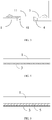
- FIG. 4 is a cross-sectional view showing a joint of an adhesive member and a circuit board according to an example
- FIG. 5 is a cross-sectional view showing a joint of an adhesive member and a circuit board according to another example.
- the adhesive member 3 is directly attached to a target carrier.
- the adhesive member 3 can be directly attached to the target carrier to simplify processing.
- the target carrier is the circuit board 1 and/or the support member 4, and FIG. 4 only takes the circuit board 1 is taken as example.
- the microphone further includes a connecting layer 5.
- the connecting layer 5 includes two adhesive surfaces disposed oppositely, the adhesive surfaces adhering to the adhesive member 3 and the target carrier, respectively.
- the adhesive member 3 has a different adhesiveness than the connecting layer 5, so that when the adhesive member 3 cannot be stably bonded to the target carrier, a stable attachment between the adhesive member 3 and the target carrier is achieved by the connecting layer 5.
- the adhesive member 3 may be formed in a variety of material to achieve desired adhesion effect.
- the target carrier is the circuit board 1 and/or the support member 4, and FIG. 5 only takes the circuit board 1 is taken as example.
- the material of the adhesive member 3 is not particularly limited, and it may be a viscous gel, a highly viscous oil, or an adhesive substance.
- the circuit board 1 includes a flexible circuit board.
- the flexible circuit board Compared with a printed circuit board, the flexible circuit board has the characteristics of high wiring density, light weight, little thickness, and good bending property.
- the microphone provided with the flexible circuit board can be more fittingly assembled with other components due to the good bending property of the flexible circuit board.
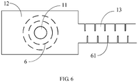
- FIG. 6 is a top view of a structure of a microphone according to an example.
- the circuit board 1 includes a first flexible circuit board 12 covering the cavity 211.
- the first flexible circuit board 12 is provided with a sound receiving hole 11, and the sound receiving hole 11 is connected to the cavity 211.
- the first flexible circuit board 12 may generate protrusion defamation or depression defamation with the sound receiving hole 11 as a center.
- the first flexible circuit board 12 can be stably attached to a protruded or recessed component to improve the mounting stability of the microphone.
- the first flexible circuit board 12 is provided with slits 6 distributed around the sound receiving hole 11.
- slits 6 By disposing the slits 6 around the sound receiving hole 11, extensibility and stretchability of the first flexible circuit board 12 are further improved, making the microphone suitable for different installation requirements.
- the signal converter 2 includes a Micro-electromechanical Systems (MEMS) sensor and an integrated circuit 23.
- MEMS Micro-electromechanical Systems
- the MEMS sensor includes a housing 21 and a vibrating diaphragm 22.
- the integrated circuit 23 is disposed outside the cavity 211 and electrically connected to the MEMS sensor.
- the integrated circuit 23 is connected to the first flexible circuit board 12, and includes ring-shaped components, such as a resistor, a capacitor, and the like. Compared with a straight-line structure, the ring-shaped structure reduces length and width of the component. In addition, the components with the ring-shaped structure are disposed on a thin flexible circuit board, which helps reduce size of the integrated circuit 23 and overall installation space required by the microphone.
- the circuit board 1 includes a second flexible circuit board 13 disposed outside the cavity 211, and staggered slits 61 are disposed on the second flexible circuit board 13.
- the second flexible circuit board 13 disposed outside the cavity 211 can connect the microphone with other components.
- flexibility of the second flexible circuit board 13 is further improved.
- the slits 61 are disposed along the width direction of the second flexible circuit board 13. This contributes to an increase in the elasticity of the second flexible circuit board 13. It can be understood that when the second flexible circuit board 13 is stretched, the slits 61 becomes wider and the second flexible circuit board 13 becomes longer. Elasticity of the second flexible circuit board 13 is improved by the slits 61, so that when the microphone moves relative to other components connected thereto, the second flexible circuit board 13 is still a continuous whole, thereby ensuring proper function of the microphone.
- the slits 6, and the slits 61 have various shapes, for example, the slits 6 and the slits 61 are rectangular, fusiform, linear, or the like.
- the slits 6 and 61 have arc-shaped ends and may be shaped in an ellipse, for example. Arc-shaped ends reduce stress concentration at the ends of the slits 6 and 61, and prevent the circuit board 1 from being torn at the slits 6 and 61, thereby ensuring the safety of the terminal device.
- the microphone further includes a housing 7 that houses the signal converter 2, and the housing 7 is connected to the circuit board 1.
- the housing 7 provides a stable working space for the signal converter 2 to ensure proper function of the microphone.
- An example of the present disclosure further provides a terminal device, where the terminal device includes the above-mentioned microphone. Since the terminal device has the above-mentioned microphone, it also has the beneficial effects of the above-mentioned microphone, and details are not described herein again.
Landscapes
- Engineering & Computer Science (AREA)
- Physics & Mathematics (AREA)
- Acoustics & Sound (AREA)
- Signal Processing (AREA)
- Microelectronics & Electronic Packaging (AREA)
- Health & Medical Sciences (AREA)
- Otolaryngology (AREA)
- Computer Hardware Design (AREA)
- Multimedia (AREA)
- Details Of Audible-Bandwidth Transducers (AREA)
- Electrostatic, Electromagnetic, Magneto- Strictive, And Variable-Resistance Transducers (AREA)
Abstract
Description
- The present disclosure relates to the field of terminal device technologies, and in particular, to a microphone and a terminal device.
- A microphone is an integral part of a terminal device. A microphone may include a signal converter and a circuit board. The signal converter may include a housing which forms a cavity, and a vibrating diaphragm located in the cavity; the sound receiving hole may be disposed on the circuit board. The signal converter may be connected to the circuit board so that the vibrating diaphragm is aligned with the sound receiving hole. A sound signal may be transmitted to the cavity through the sound receiving hole to drive the vibrating diaphragm to vibrate, thereby causing the signal converter to convert the sound signal into an electrical signal.
- However, during use, impurities from outside the microphone may enter the cavity through the sound receiving hole and stay on the vibrating diaphragm. Accumulated impurities may scratch and pierce the vibrating diaphragm as the vibrating diaphragm vibrates, thereby affecting proper function of the microphone.
- This Summary is provided to introduce a selection of aspects of the present disclosure in a simplified form that are further described below in the Detailed Description. This Summary is not intended to identify key features or essential features of the claimed subject matter, nor is it intended to be used to limit the scope of the claimed subject matter.
- Aspects of the disclosure provide a microphone. The microphone includes a circuit board including a sound receiving hole; a signal converter configured to convert a sound signal into an electrical signal, wherein the signal converter includes a housing that forms a cavity, and wherein the cavity is connected to the sound receiving hole; and an adhesive member disposed in the cavity.
- In an example, the adhesive member is attached to a part of the circuit board that the cavity covers.
- In another example, the adhesive member extends from the cavity to the sound receiving hole.
- In yet another example, the adhesive member is at least partially attached to a sidewall of the sound receiving hole.
- According to another aspect, the circuit board includes a supporting member attached to a sidewall of the sound receiving hole and located in the sound receiving hole, and the adhesive member is at least partially attached to the supporting member.
- According to yet another aspect, the supporting member includes a supporting table extending towards an axis of the sound receiving hole, and the supporting table is configured to support the adhesive member.
- According to yet another aspect, the microphone further includes a connecting layer including two adhesive surfaces disposed oppositely, wherein the two adhesive surfaces adhere to the adhesive member and a target carrier to which the adhesive member is to be attached, respectively.
- According to yet another aspect, the circuit board includes a first flexible circuit board covering the cavity, and the sound receiving hole is disposed on the first flexible circuit board.
- According to yet another aspect, the microphone further includes slits disposed around the sound receiving hole on the first flexible circuit board.
- According to yet another aspect, the signal converter further includes an integrated circuit, and the integrated circuit is connected to the first flexible circuit board and disposed outside the cavity, and includes a component with a ring-shaped structure.
- According to yet another aspect, the circuit board includes a second flexible circuit board located outside the cavity, and the second flexible circuit board includes staggered slits provided thereon.
- In an example, the staggered slits include arc-shaped ends.
- In another example, the adhesive member covers a free area on the circuit board.
- In yet another example, the supporting member is sleeved in the sound receiving hole.
- In yet another example, the supporting member and the circuit board are integrally formed.
- According to an aspect, the signal converter includes a vibrating diaphragm disposed in the cavity.
- Aspects of the disclosure also provide a terminal device. The terminal device includes a microphone, which includes a circuit board including a sound receiving hole; a signal converter configured to convert a sound signal into an electrical signal, wherein the signal converter includes a housing that forms a cavity, and wherein the cavity is connected to the sound receiving hole; and an adhesive member disposed in the cavity.
- It is to be understood that both the foregoing general description and the following detailed description are illustrative and explanatory only and are not restrictive of the present disclosure.
- The accompanying drawings, which are incorporated in and constitute a part of the specification, illustrate aspects consistent with the present disclosure and, together with the description, serve to explain the principles of the present disclosure.
-
FIG. 1 is a cross-sectional view of a structure of a microphone according to an exemplary aspect of the present disclosure; -
FIG. 2 is a cross-sectional view of a structure of a microphone according to an exemplary aspect of the present disclosure; -
FIG. 3 is a cross-sectional view of a structure of a sound receiving hole in a microphone according to an exemplary aspect of the present disclosure; -
FIG. 4 is a cross-sectional view showing a joint of an adhesive member and a circuit board according to an exemplary aspect of the present disclosure; -
FIG. 5 is a cross-sectional view showing a joint of an adhesive member and a circuit board according to an exemplary aspect of the present disclosure; -
FIG. 6 is a top view of a structure of a microphone according to an exemplary aspect of the present disclosure. - The specific aspects of the present disclosure, which have been illustrated by the accompanying drawings described above, will be described in detail below. These accompanying drawings and description are not intended to limit the scope of the present disclosure in any manner, but to explain the concept of the present disclosure to those skilled in the art via referencing specific aspects.
- Reference will now be made in detail to exemplary aspects, examples of which are illustrated in the accompanying drawings. The following description refers to the accompanying drawings in which the same numbers in different drawings represent the same or similar elements unless otherwise represented. The implementations set forth in the following description of illustrative aspects do not represent all implementations consistent with the disclosure. Instead, they are merely examples of apparatuses and methods consistent with aspects related to the disclosure as recited in the appended claims.
-
FIG. 1 is a cross-sectional view of a structure of a microphone according to an example. As shown inFIG. 1 , the microphone includes acircuit board 1, asignal converter 2, and anadhesive member 3. - The
circuit board 1 is formed with asound receiving hole 11. Thesignal converter 2 is configured to convert a sound signal into an electrical signal and includes ahousing 21 which forms acavity 211. Thesignal converter 2 is attached to thecircuit board 1, and thecavity 211 is connected to thesound receiving hole 11. Theadhesive member 3 is disposed in thecavity 211. - In some examples, the
signal converter 2 further includes a signal converting element, such as avibrating diaphragm 22, disposed in thecavity 211. In this case, a sound wave is transmitted into thecavity 211 of thesignal converter 2 through thesound receiving hole 11 in thecircuit board 1, so that thevibrating diaphragm 22 disposed in thecavity 211 vibrates with the sound wave, thereby generating an electrical signal corresponding to the sound wave. - Since the
adhesive member 3 is provided in thecavity 211, impurities entering thecavity 211 through thesound receiving hole 11 may be directly adhered to theadhesive member 3, so that the impurities do not contact components other than theadhesive member 3 in thecavity 211. In addition, by shaking the microphone or other similar operations, impurities in thecavity 211 may be adhered to theadhesive member 3 during motion, so that the impurities do not repeatedly contact components other than theadhesive member 3. - For a signal converting element exemplified by the vibrating
diaphragm 22, by using theadhesive member 3 of the microphone provided by the examples of the present disclosure, the amount of impurities in contact with the vibratingdiaphragm 22 is reduced, and the repeated contact of the impurities with the vibratingdiaphragm 22 is avoided. Theadhesive member 3 helps to weaken the impact and wear of impurities on thediaphragm 22, avoids damage to thediaphragm 22, and ensures proper function of the microphone, so as to extend the life of the microphone. - In some examples, the
adhesive member 3 in thecavity 211 is in a sheet shape or a rod shape. In an example, theadhesive member 3 is a sheet-shaped structure. Being sheet-shaped contributes to an effective adhesion area of theadhesive member 3 to sufficiently adhere the impurities. - In an example, as shown in
FIG. 1 , theadhesive member 3 is attached to a part of thecircuit board 1 corresponding to thecavity 211. Theadhesive member 3 is attached to a part of thecircuit board 1 which thecavity 211 covers. It is noted that thecircuit board 1 is also provided with wiring, solder joints, etc., and theadhesive member 3 is only attached to part of thecircuit board 1 where no wiring or the like is disposed, so as to not affect proper function of thecircuit board 1. In this example, the impurities in thecavity 211 are adhered by theadhesive member 3 attached to thecircuit board 1. - In some examples, the
adhesive member 3 covers part of thecircuit board 1 where no wiring, solder joints, or the like is provided, which is equivalent to an adhesive layer having a hollowed-out structure on thecircuit board 1. In this way, theadhesive member 3 will be given a maximum adhesion area for maximum adhesion. Part of thecircuit board 1 where no wiring, solder joints, or the like is provided is also referred to as a free area. -
FIG. 2 is a cross-sectional view of a structure of a microphone according to another example, andFIG. 3 is a partial cross-sectional view of a sound receiving hole in a microphone according to another example. - In an example, as shown in
FIG. 2 , theadhesive member 3 extends from thecavity 211 to thesound receiving hole 11. Theadhesive member 3 extending to thesound receiving hole 11 prevents impurities from entering thecavity 211 through thesound receiving hole 11, thereby fundamentally reducing the amount of impurities entering thecavity 211 and preventing damage to the vibratingdiaphragm 22 by impurities. - In some examples, as shown in
FIG. 2 , theadhesive member 3 at least partially covers a sidewall of thesound receiving hole 11. This approach eliminates the need to add additional components to further reduce the amount of impurities entering thecavity 211 and helps to control production costs. - In some examples, as shown in
FIG. 3 , thecircuit board 1 includes at least one supportingmember 4 respectively attached to a sidewall of thesound receiving hole 11 and located in thesound receiving hole 11, and theadhesive member 3 is at least partially attached to the supportingmember 4. The supportingmember 4 is able to better support theadhesive member 3, so as to prevent the blocking of thesound receiving hole 11 by the peeling or deformation of theadhesive member 3, thereby ensuring proper function of the microphone. - In some examples, the supporting
member 4 has an annular structure and is sleeved in thesound receiving hole 11 to facilitate replacement of theadhesive member 3. Theadhesive member 3 needs to be replaced after a period of usage of, for example, 24 months. By removing the supportingmember 4 sleeved in thesound receiving hole 11, an end of theadhesive member 3 near thesound receiving hole 11 is detached from the supportingmember 4. In this way, replacement of theadhesive member 3 becomes easier. In an example, the supportingmember 4 includes a supporting table 41 extending towards an axis of thesound receiving hole 11. The supporting tables 41 increases a contact area for theadhesive member 3, ensuring that theadhesive member 3 is stably attached along the sidewall of thesound receiving hole 11. The number and the installation position of the supporting tables 41 are not specifically limited. For example, as shown inFIG. 3 , two supporting tables 41 may be respectively disposed near two ends of thesound receiving hole 11 on the supportingmember 4. - In some examples, to prevent the supporting
member 4 from affecting sound receiving effect of thesound receiving hole 11, the size of thesound receiving hole 11 may be enlarged. In some examples, the supportingmember 4 and thecircuit board 1 may be integrally formed, which can stably support theadhesive member 3 and avoid adding additional components to control production cost. -
FIG. 4 is a cross-sectional view showing a joint of an adhesive member and a circuit board according to an example;FIG. 5 is a cross-sectional view showing a joint of an adhesive member and a circuit board according to another example. - In an example, as shown in
FIG. 4 , theadhesive member 3 is directly attached to a target carrier. When theadhesive member 3 is stably bonded to the target carrier, theadhesive member 3 can be directly attached to the target carrier to simplify processing. The target carrier is thecircuit board 1 and/or thesupport member 4, andFIG. 4 only takes thecircuit board 1 is taken as example. - In another example, as shown in
FIG. 5 , the microphone further includes a connectinglayer 5. The connectinglayer 5 includes two adhesive surfaces disposed oppositely, the adhesive surfaces adhering to theadhesive member 3 and the target carrier, respectively. In this example, theadhesive member 3 has a different adhesiveness than the connectinglayer 5, so that when theadhesive member 3 cannot be stably bonded to the target carrier, a stable attachment between theadhesive member 3 and the target carrier is achieved by the connectinglayer 5. In this way, theadhesive member 3 may be formed in a variety of material to achieve desired adhesion effect. The target carrier is thecircuit board 1 and/or thesupport member 4, andFIG. 5 only takes thecircuit board 1 is taken as example. - In examples of the present disclosure, the material of the
adhesive member 3 is not particularly limited, and it may be a viscous gel, a highly viscous oil, or an adhesive substance. - In an example, the
circuit board 1 includes a flexible circuit board. Compared with a printed circuit board, the flexible circuit board has the characteristics of high wiring density, light weight, little thickness, and good bending property. The microphone provided with the flexible circuit board can be more fittingly assembled with other components due to the good bending property of the flexible circuit board. -
FIG. 6 is a top view of a structure of a microphone according to an example. In an example, as shown inFIG. 6 , thecircuit board 1 includes a firstflexible circuit board 12 covering thecavity 211. The firstflexible circuit board 12 is provided with asound receiving hole 11, and thesound receiving hole 11 is connected to thecavity 211. In this example, by disposing thesound receiving hole 11 on the firstflexible circuit board 12, extensibility and flexibility of the firstflexible circuit board 12 are improved. Illustratively, in this case, the firstflexible circuit board 12 may generate protrusion defamation or depression defamation with thesound receiving hole 11 as a center. In this case, the firstflexible circuit board 12 can be stably attached to a protruded or recessed component to improve the mounting stability of the microphone. - Further, as shown in
FIG. 6 , the firstflexible circuit board 12 is provided withslits 6 distributed around thesound receiving hole 11. By disposing theslits 6 around thesound receiving hole 11, extensibility and stretchability of the firstflexible circuit board 12 are further improved, making the microphone suitable for different installation requirements. - In such a case, in reference to both
FIGs. 1 and6 , in some examples, thesignal converter 2 includes a Micro-electromechanical Systems (MEMS) sensor and anintegrated circuit 23. The MEMS sensor includes ahousing 21 and a vibratingdiaphragm 22. Theintegrated circuit 23 is disposed outside thecavity 211 and electrically connected to the MEMS sensor. - Further, the
integrated circuit 23 is connected to the firstflexible circuit board 12, and includes ring-shaped components, such as a resistor, a capacitor, and the like. Compared with a straight-line structure, the ring-shaped structure reduces length and width of the component. In addition, the components with the ring-shaped structure are disposed on a thin flexible circuit board, which helps reduce size of theintegrated circuit 23 and overall installation space required by the microphone. - In an example, as shown in
FIG. 6 , thecircuit board 1 includes a secondflexible circuit board 13 disposed outside thecavity 211, and staggeredslits 61 are disposed on the secondflexible circuit board 13. - The second
flexible circuit board 13 disposed outside thecavity 211 can connect the microphone with other components. By disposing the staggered slits 61 on the secondflexible circuit board 13, flexibility of the secondflexible circuit board 13 is further improved. For example, as shown inFIG. 6 , theslits 61 are disposed along the width direction of the secondflexible circuit board 13. This contributes to an increase in the elasticity of the secondflexible circuit board 13. It can be understood that when the secondflexible circuit board 13 is stretched, theslits 61 becomes wider and the secondflexible circuit board 13 becomes longer. Elasticity of the secondflexible circuit board 13 is improved by theslits 61, so that when the microphone moves relative to other components connected thereto, the secondflexible circuit board 13 is still a continuous whole, thereby ensuring proper function of the microphone. - In some examples, the
slits 6, and theslits 61 have various shapes, for example, theslits 6 and theslits 61 are rectangular, fusiform, linear, or the like. In some examples, theslits slits circuit board 1 from being torn at theslits - In an example, as shown in
FIGs. 1 and 2 , the microphone further includes ahousing 7 that houses thesignal converter 2, and thehousing 7 is connected to thecircuit board 1. Thehousing 7 provides a stable working space for thesignal converter 2 to ensure proper function of the microphone. - An example of the present disclosure further provides a terminal device, where the terminal device includes the above-mentioned microphone. Since the terminal device has the above-mentioned microphone, it also has the beneficial effects of the above-mentioned microphone, and details are not described herein again.
- Other aspects of the present disclosure will be apparent to those skilled in the art after considering the specification and what disclosed herein. The present disclosure is intended to cover any variations, uses, or adaptations of the present disclosure, which are in accordance with the general principles of the disclosure and include common general knowledge or common technical means in the art that are not disclosed in the present disclosure. The specification and examples are to be regarded as illustrative only, and the true scope and spirit of the present disclosure are indicated by the appended claims.
- It is to be understood that the disclosure is not limited to the details described and expressed in the accompanying drawings and is subject to changed and variations within its scope. The scope of the disclosure is to be limited only by the appended claims.
Claims (15)
- A microphone, characterized in that, the microphone comprising:a circuit board including a sound receiving hole;a signal converter configured to convert a sound signal into an electrical signal, wherein the signal converter includes a housing that forms a cavity, and wherein the cavity is connected to the sound receiving hole; andan adhesive member disposed in the cavity.
- The microphone according to claim 1,
wherein the adhesive member is attached to a part of the circuit board that the cavity covers;
wherein the adhesive member covers a free area on the circuit board. - The microphone according to claim 1 or claim 2, wherein the adhesive member extends from the cavity to the sound receiving hole.
- The microphone according to any claims of 1-3, wherein the adhesive member is at least partially attached to a sidewall of the sound receiving hole.
- The microphone according to any claims of 1-4, wherein the circuit board includes a supporting member attached to a sidewall of the sound receiving hole and located in the sound receiving hole, and
wherein the adhesive member is at least partially attached to the supporting member. - The microphone according to claim 5, wherein the supporting member includes a supporting table extending towards an axis of the sound receiving hole, and
wherein the supporting table is configured to support the adhesive member. - The microphone according to any claims of 1-6, further comprising:
a connecting layer including two adhesive surfaces disposed oppositely, wherein the two adhesive surfaces adhere to the adhesive member and a target carrier to which the adhesive member is to be attached, respectively. - The microphone according to any claims of 1-7, wherein the circuit board includes a first flexible circuit board covering the cavity, and
wherein the sound receiving hole is disposed on the first flexible circuit board. - The microphone according to claim 8, further comprising:
slits disposed around the sound receiving hole on the first flexible circuit board. - The microphone according to claim 8, wherein the signal converter further includes an integrated circuit, and
wherein the integrated circuit is connected to the first flexible circuit board and disposed outside the cavity, and includes a component with a ring-shaped structure. - The microphone according to any claims of 1-10, wherein the circuit board includes a second flexible circuit board located outside the cavity, and
wherein the second flexible circuit board includes staggered slits provided thereon. - The microphone according to claim 11, wherein the staggered slits include arc-shaped ends.
- The microphone according to claim 5, wherein the supporting member is sleeved in the sound receiving hole.
- The microphone according to claim 5, wherein the supporting member and the circuit board are integrally formed.
- A terminal device, comprising the microphone of any claims of 1-14.
Applications Claiming Priority (1)
| Application Number | Priority Date | Filing Date | Title |
|---|---|---|---|
| CN201811132764.0A CN110958541A (en) | 2018-09-27 | 2018-09-27 | Microphone module and terminal |
Publications (2)
| Publication Number | Publication Date |
|---|---|
| EP3629590A2 true EP3629590A2 (en) | 2020-04-01 |
| EP3629590A3 EP3629590A3 (en) | 2020-06-24 |
Family
ID=68084626
Family Applications (1)
| Application Number | Title | Priority Date | Filing Date |
|---|---|---|---|
| EP19200142.8A Withdrawn EP3629590A3 (en) | 2018-09-27 | 2019-09-27 | Microphone and terminal device |
Country Status (3)
| Country | Link |
|---|---|
| US (1) | US10924833B2 (en) |
| EP (1) | EP3629590A3 (en) |
| CN (1) | CN110958541A (en) |
Citations (1)
| Publication number | Priority date | Publication date | Assignee | Title |
|---|---|---|---|---|
| CN205305107U (en) * | 2015-12-25 | 2016-06-08 | 歌尔声学股份有限公司 | MEMS (Micro -electromechanical system) microphone |
Family Cites Families (18)
| Publication number | Priority date | Publication date | Assignee | Title |
|---|---|---|---|---|
| CN2634534Y (en) * | 2003-07-10 | 2004-08-18 | 文麦股份有限公司 | Fixing device for computer key board bowl shape elastic rubber |
| JP2009081289A (en) | 2007-09-26 | 2009-04-16 | Denso Corp | Semiconductor device, fixing structure thereof, and foreign matter removing method thereof |
| JP2010187076A (en) * | 2009-02-10 | 2010-08-26 | Funai Electric Co Ltd | Microphone unit |
| US20130327221A1 (en) | 2012-06-06 | 2013-12-12 | Honeywell International Inc. | Systems and methods for particle contaminant entrapment |
| KR101346583B1 (en) | 2013-05-23 | 2014-01-03 | (주)에스엠인스트루먼트 | Sound measuring apparatus having flexible substrate using mems microphone and method for making the apparatus |
| CN103945314B (en) * | 2014-04-24 | 2018-07-06 | 歌尔股份有限公司 | Microphone |
| TWI594940B (en) * | 2014-04-30 | 2017-08-11 | 鑫創科技股份有限公司 | Micro-electrical-mechanical system (mems) microphone |
| WO2016029378A1 (en) | 2014-08-27 | 2016-03-03 | Goertek. Inc | Mems device with valve mechanism |
| CN204465862U (en) | 2015-01-23 | 2015-07-08 | 瑞声声学科技(深圳)有限公司 | Package Structure of MEMS Microphone |
| US10020357B2 (en) * | 2015-04-10 | 2018-07-10 | Cirrus Logic, Inc. | Sense resistor surroundingly positioned near or around and integrated with an output connection |
| US10009523B2 (en) * | 2015-05-11 | 2018-06-26 | Samsung Electro-Mechanics Co., Ltd. | Electronic module and method of manufacturing the same |
| CN105242427B (en) * | 2015-10-27 | 2019-06-11 | 南京中电熊猫液晶显示科技有限公司 | COF flexible circuit board |
| CN108323240B (en) * | 2017-05-31 | 2020-09-22 | 潍坊歌尔微电子有限公司 | MEMS microphone and manufacturing method thereof |
| GB2563461B (en) * | 2017-06-16 | 2021-11-10 | Cirrus Logic Int Semiconductor Ltd | Transducer packaging |
| US11274034B2 (en) * | 2017-07-26 | 2022-03-15 | Knowles Electronics, Llc | Acoustic relief in MEMS |
| CN207543340U (en) * | 2017-12-19 | 2018-06-26 | 深圳市国邦电子科技有限公司 | A kind of silicon microphone |
| CN207766455U (en) | 2017-12-26 | 2018-08-24 | 歌尔科技有限公司 | Mems microphone |
| CN208739400U (en) * | 2018-09-27 | 2019-04-12 | 北京小米移动软件有限公司 | Microphone module, terminal |
-
2018
- 2018-09-27 CN CN201811132764.0A patent/CN110958541A/en active Pending
-
2019
- 2019-09-26 US US16/584,252 patent/US10924833B2/en not_active Expired - Fee Related
- 2019-09-27 EP EP19200142.8A patent/EP3629590A3/en not_active Withdrawn
Patent Citations (1)
| Publication number | Priority date | Publication date | Assignee | Title |
|---|---|---|---|---|
| CN205305107U (en) * | 2015-12-25 | 2016-06-08 | 歌尔声学股份有限公司 | MEMS (Micro -electromechanical system) microphone |
Also Published As
| Publication number | Publication date |
|---|---|
| EP3629590A3 (en) | 2020-06-24 |
| CN110958541A (en) | 2020-04-03 |
| US20200107092A1 (en) | 2020-04-02 |
| US10924833B2 (en) | 2021-02-16 |
Similar Documents
| Publication | Publication Date | Title |
|---|---|---|
| JP6227136B2 (en) | Device for connecting a plurality of electrical paths with a plurality of electrical contacts | |
| US8247954B2 (en) | Electronic component device and method for manufacturing the same | |
| JP4876292B2 (en) | Electroacoustic transducer having a moving coil and an elastic holding element for the connecting lead of the moving coil | |
| GB2356914A (en) | Device and method for mounting vibrator | |
| EP0757505A3 (en) | Piezoelectric element and piezoelectric acoustic device | |
| US10924833B2 (en) | Microphone and terminal device | |
| EP3628639B1 (en) | Microphone module with particle contaminant protection | |
| JP6516626B2 (en) | Microphone device | |
| CN108566601B (en) | Sound producing device | |
| CN206948600U (en) | A kind of electroacoustic transducer and electronic equipment | |
| WO2018061320A1 (en) | Piezoelectric sounding component | |
| CN110915236B (en) | Sound transducer with MEMS unit | |
| CN211090109U (en) | PCB and MEMS sensor applying same | |
| CN208739400U (en) | Microphone module, terminal | |
| JP2014165568A (en) | Headset | |
| US20240397644A1 (en) | Vehicle-mounted large-screen device with vibration | |
| KR102059417B1 (en) | Bluetooth earbud | |
| JP2007511997A (en) | Commutators for electrical equipment | |
| CN210807650U (en) | Waterproof dustproof antivibration silicon material microphone | |
| CN210641123U (en) | PCB and MEMS sensor applying same | |
| EP3629589A1 (en) | Microphone and terminal device including the same | |
| KR101640443B1 (en) | Vibrator | |
| CN217591031U (en) | Bone conduction microphone | |
| JPH11355892A (en) | Piezoelectric diaphragm and piezoelectric acoustic component using the piezoelectric diaphragm | |
| JP4867242B2 (en) | Field equipment |
Legal Events
| Date | Code | Title | Description |
|---|---|---|---|
| PUAI | Public reference made under article 153(3) epc to a published international application that has entered the european phase |
Free format text: ORIGINAL CODE: 0009012 |
|
| STAA | Information on the status of an ep patent application or granted ep patent |
Free format text: STATUS: THE APPLICATION HAS BEEN PUBLISHED |
|
| AK | Designated contracting states |
Kind code of ref document: A2 Designated state(s): AL AT BE BG CH CY CZ DE DK EE ES FI FR GB GR HR HU IE IS IT LI LT LU LV MC MK MT NL NO PL PT RO RS SE SI SK SM TR |
|
| AX | Request for extension of the european patent |
Extension state: BA ME |
|
| PUAL | Search report despatched |
Free format text: ORIGINAL CODE: 0009013 |
|
| AK | Designated contracting states |
Kind code of ref document: A3 Designated state(s): AL AT BE BG CH CY CZ DE DK EE ES FI FR GB GR HR HU IE IS IT LI LT LU LV MC MK MT NL NO PL PT RO RS SE SI SK SM TR |
|
| AX | Request for extension of the european patent |
Extension state: BA ME |
|
| RIC1 | Information provided on ipc code assigned before grant |
Ipc: H04R 19/00 20060101ALN20200520BHEP Ipc: B81B 7/00 20060101ALI20200520BHEP Ipc: H04R 1/08 20060101AFI20200520BHEP Ipc: H04R 19/04 20060101ALI20200520BHEP |
|
| STAA | Information on the status of an ep patent application or granted ep patent |
Free format text: STATUS: REQUEST FOR EXAMINATION WAS MADE |
|
| 17P | Request for examination filed |
Effective date: 20201216 |
|
| RBV | Designated contracting states (corrected) |
Designated state(s): AL AT BE BG CH CY CZ DE DK EE ES FI FR GB GR HR HU IE IS IT LI LT LU LV MC MK MT NL NO PL PT RO RS SE SI SK SM TR |
|
| STAA | Information on the status of an ep patent application or granted ep patent |
Free format text: STATUS: EXAMINATION IS IN PROGRESS |
|
| 17Q | First examination report despatched |
Effective date: 20220624 |
|
| GRAP | Despatch of communication of intention to grant a patent |
Free format text: ORIGINAL CODE: EPIDOSNIGR1 |
|
| STAA | Information on the status of an ep patent application or granted ep patent |
Free format text: STATUS: GRANT OF PATENT IS INTENDED |
|
| INTG | Intention to grant announced |
Effective date: 20240708 |
|
| RIN1 | Information on inventor provided before grant (corrected) |
Inventor name: DU, HUI Inventor name: YEN, CHIAFU |
|
| STAA | Information on the status of an ep patent application or granted ep patent |
Free format text: STATUS: THE APPLICATION IS DEEMED TO BE WITHDRAWN |
|
| 18D | Application deemed to be withdrawn |
Effective date: 20241109 |