EP3629556B2 - Sensorvorrichtung, system und entsprechendes verfahren - Google Patents
Sensorvorrichtung, system und entsprechendes verfahren Download PDFInfo
- Publication number
- EP3629556B2 EP3629556B2 EP19200098.2A EP19200098A EP3629556B2 EP 3629556 B2 EP3629556 B2 EP 3629556B2 EP 19200098 A EP19200098 A EP 19200098A EP 3629556 B2 EP3629556 B2 EP 3629556B2
- Authority
- EP
- European Patent Office
- Prior art keywords
- sensor
- read command
- time
- signal
- estimate
- Prior art date
- Legal status (The legal status is an assumption and is not a legal conclusion. Google has not performed a legal analysis and makes no representation as to the accuracy of the status listed.)
- Active
Links
Images


Classifications
-
- G—PHYSICS
- G01—MEASURING; TESTING
- G01R—MEASURING ELECTRIC VARIABLES; MEASURING MAGNETIC VARIABLES
- G01R33/00—Arrangements or instruments for measuring magnetic variables
- G01R33/02—Measuring direction or magnitude of magnetic fields or magnetic flux
-
- H—ELECTRICITY
- H04—ELECTRIC COMMUNICATION TECHNIQUE
- H04L—TRANSMISSION OF DIGITAL INFORMATION, e.g. TELEGRAPHIC COMMUNICATION
- H04L67/00—Network arrangements or protocols for supporting network services or applications
- H04L67/01—Protocols
- H04L67/12—Protocols specially adapted for proprietary or special-purpose networking environments, e.g. medical networks, sensor networks, networks in vehicles or remote metering networks
-
- G—PHYSICS
- G01—MEASURING; TESTING
- G01D—MEASURING NOT SPECIALLY ADAPTED FOR A SPECIFIC VARIABLE; ARRANGEMENTS FOR MEASURING TWO OR MORE VARIABLES NOT COVERED IN A SINGLE OTHER SUBCLASS; TARIFF METERING APPARATUS; MEASURING OR TESTING NOT OTHERWISE PROVIDED FOR
- G01D5/00—Mechanical means for transferring the output of a sensing member; Means for converting the output of a sensing member to another variable where the form or nature of the sensing member does not constrain the means for converting; Transducers not specially adapted for a specific variable
- G01D5/12—Mechanical means for transferring the output of a sensing member; Means for converting the output of a sensing member to another variable where the form or nature of the sensing member does not constrain the means for converting; Transducers not specially adapted for a specific variable using electric or magnetic means
- G01D5/244—Mechanical means for transferring the output of a sensing member; Means for converting the output of a sensing member to another variable where the form or nature of the sensing member does not constrain the means for converting; Transducers not specially adapted for a specific variable using electric or magnetic means influencing characteristics of pulses or pulse trains; generating pulses or pulse trains
- G01D5/24409—Interpolation using memories
-
- G—PHYSICS
- G01—MEASURING; TESTING
- G01D—MEASURING NOT SPECIALLY ADAPTED FOR A SPECIFIC VARIABLE; ARRANGEMENTS FOR MEASURING TWO OR MORE VARIABLES NOT COVERED IN A SINGLE OTHER SUBCLASS; TARIFF METERING APPARATUS; MEASURING OR TESTING NOT OTHERWISE PROVIDED FOR
- G01D5/00—Mechanical means for transferring the output of a sensing member; Means for converting the output of a sensing member to another variable where the form or nature of the sensing member does not constrain the means for converting; Transducers not specially adapted for a specific variable
- G01D5/12—Mechanical means for transferring the output of a sensing member; Means for converting the output of a sensing member to another variable where the form or nature of the sensing member does not constrain the means for converting; Transducers not specially adapted for a specific variable using electric or magnetic means
- G01D5/244—Mechanical means for transferring the output of a sensing member; Means for converting the output of a sensing member to another variable where the form or nature of the sensing member does not constrain the means for converting; Transducers not specially adapted for a specific variable using electric or magnetic means influencing characteristics of pulses or pulse trains; generating pulses or pulse trains
- G01D5/24471—Error correction
- G01D5/24476—Signal processing
-
- G—PHYSICS
- G01—MEASURING; TESTING
- G01R—MEASURING ELECTRIC VARIABLES; MEASURING MAGNETIC VARIABLES
- G01R33/00—Arrangements or instruments for measuring magnetic variables
- G01R33/02—Measuring direction or magnitude of magnetic fields or magnetic flux
- G01R33/022—Measuring gradient
-
- G—PHYSICS
- G01—MEASURING; TESTING
- G01R—MEASURING ELECTRIC VARIABLES; MEASURING MAGNETIC VARIABLES
- G01R33/00—Arrangements or instruments for measuring magnetic variables
- G01R33/02—Measuring direction or magnitude of magnetic fields or magnetic flux
- G01R33/06—Measuring direction or magnitude of magnetic fields or magnetic flux using galvano-magnetic devices
- G01R33/07—Hall effect devices
- G01R33/077—Vertical Hall-effect devices
-
- G—PHYSICS
- G01—MEASURING; TESTING
- G01D—MEASURING NOT SPECIALLY ADAPTED FOR A SPECIFIC VARIABLE; ARRANGEMENTS FOR MEASURING TWO OR MORE VARIABLES NOT COVERED IN A SINGLE OTHER SUBCLASS; TARIFF METERING APPARATUS; MEASURING OR TESTING NOT OTHERWISE PROVIDED FOR
- G01D3/00—Indicating or recording apparatus with provision for the special purposes referred to in the subgroups
- G01D3/028—Indicating or recording apparatus with provision for the special purposes referred to in the subgroups mitigating undesired influences, e.g. temperature, pressure
- G01D3/036—Indicating or recording apparatus with provision for the special purposes referred to in the subgroups mitigating undesired influences, e.g. temperature, pressure on measuring arrangements themselves
Definitions
- the invention relates to the field of sensor devices for reporting sensor data via a bus communication system. More specifically it relates to a sensor device, a system comprising such sensor devices and a method for communicating sensor data via a bus system.
- US 2017/0163366 discloses an approach that enables robust, high-speed communication of sensor data.
- An electronic control unit (ECU) outputs a synchronization signal to a sensor bus.
- One or more sensors connected to the bus then samples sensor data in response to the synchronization signal and transmit the sampled sensor data to the sensor bus.
- FIG. 1 illustrates this approach.
- the sensor device receives the trigger signal 31 sent by the ECU, the sensor signal S is sampled, cf. sample n.
- the sensor readout is continuously sampled at a sampling frequency f s (corresponding to a sampling period T s ).
- a trigger signal 31 is received from the ECU
- the last sampled value, cf. sample n-1 is reported.
- Document US 2018/164125 A1 discloses a device which may include a sensor, a sampling unit, and an interpolator.
- the sensor may be configured to sense motion and output a sensed signal.
- the sampling unit may be configured to sample the sensed signal with a sensor clocking signal to generate a plurality of sampled values.
- the interpolator may be coupled to the sampling unit and may be configured to receive the plurality of sampled values, the sensor clocking signal. and a reference clocking signal external to the device.
- the interpolator may be configured to interpolate the plurality of sampled values based on the reference clocking signal and further based on the sensor clocking signal to generate a plurality of output values.
- a controlled latency e.g. a substantially constant data age
- a bus-connected sensor device can be achieved in a bus-connected sensor device.
- a latency can be controlled as a sum of a predetermined offset and a protocol latency for transmitting data from a sensor to an electronic control unit.
- Both the predetermined offset and the protocol latency may be substantially (e.g. up to negligible variations, e.g. of the order of 10 ⁇ s, or 5 ⁇ s ,or 2 ⁇ s, or 1 ⁇ s and less) constant and repeatable.
- It is an object of embodiments of the present invention to provide a sensor system comprising a master device and a plurality of sensor devices connected to a digital bus, which sensor devices are capable of providing a value indicative of a respective physical quantity to be measured, at substantially the same moment in time.
- It is an object of embodiments of the present invention to provide a sensor system comprising a master device (e.g. an ECU) and a plurality of sensor devices connected to a digital bus (e.g. a CAN-bus or CAN-FD bus in an automotive environment), configured for obtaining sensor data from the plurality of sensor devices with a reduced jitter between the measurement data provided by each sensor device, (e.g. in the order of 1 ⁇ s and less), without synchronizing the clocks of the plurality of sensor devices at which samples are taken.
- a master device e.g. an ECU
- a digital bus e.g. a CAN-bus or CAN-FD bus in an automotive environment
- the present invention relates to a sensor device as defined by claim 1.
- the senor device is a sensor device for use in an automotive environment, e.g. for motor control.
- the digital communication bus is a CAN-bus.
- the digital communication bus is a CAN-FD-bus.
- the read command is a periodic signal.
- the read command is an aperiodic signal (i.e. does not repeat at constant time intervals).
- the digital communication bus is a bidirectional communication bus.
- the sensor unit is a magnetic sensor unit
- the physical quantity to be measured is a magnetic field value, or a value derived therefrom (e.g. a magnetic field gradient).
- the read command may be a broadcast read command which simultaneously targets a plurality of sensor devices connected to the bus.
- the estimator may be adapted for calculating the estimate upon receiving a request from the bus interface when the read command has been received.
- the bus interface is adapted for providing a request signal to the estimator when said read command is received, and said estimator is adapted for calculating said estimate upon receipt of said request signal.
- the estimator may be adapted for repeatedly updating the estimate and making the updated estimate available to the bus interface for use when receiving the read command.
- the storage memory may be adapted for storing at least a last sample and a next to last sample of the signal
- the estimator may be adapted for calculating the estimate by an extrapolation of the data stored in the storage memory to the reference point in time.
- the interpolator may constantly interpolating at an interpolation frequency.
- the interpolation frequency may be preferably an integer multiple of the sampling frequency, and may be at least 2.0 or at least 5.0 or at least 10 times higher than the average read command frequency, and may be asynchronous to the read-command.
- the interpolator may contains a memory or a FIFO, and may be adapted for output one the interpolated value already present in the memory or FIFO, which is closest in time to the time-of-arrival of the read-command minus the predefined offset, or the interpolated value directly before, or the interpolated value directly after.
- the processing unit may comprise a phase-tracking loop unit and/or a phase locked loop unit for tracking the physical quantity.
- the storage memory may be adapted for storing at least one parameter of the phase-tracking loop unit and/or of the phase locked loop unit.
- the estimator may be adapted for calculating the estimate based on an output of the phase-tracking loop unit and/or the phase locked loop unit.
- the processing unit may comprise a sigma-delta modulator.
- the sensor device may be an angular position sensor device, and the sensor unit may comprise a plurality of sensor elements arranged to produce a plurality of signals each being a function of an input quantity, such as an input phase representative of a position to be measured.
- the phase-tracking loop unit may be adapted for generating an error signal by combining the plurality of signals according to an array of weight factors stored in the storage memory, for filtering the error signal to generate an output quantity, e.g. a phase value representative of the position to be measured, as the output of the phase-tracking loop unit and for adjusting the array of weight factors based on said output quantity.
- an output quantity e.g. a phase value representative of the position to be measured
- the sensor unit may comprise a plurality of sensor elements arranged to produce a plurality of signals each being a function of an input quantity, e.g. a phase representative of a position to be measured.
- the estimator may implement a phase-tracking loop and/or a phase-locked loop for tracking the physical quantity and is adapted for generating an error signal by combining the plurality of signals with an array of weight factors.
- the sensor unit may be adapted for sampling the physical quantity or another physical quantity that is indicative of the physical quantity at a predetermined sampling frequency fs.
- the sampling frequency (f s ) and the read command are asynchronous.
- the sampling frequency (f s ) and the read command are uncorrelated signals, in the meaning that the read command may arrive at any moment in time, and that the sensor device takes samples at regular intervals irrespective of the read command.
- the predetermined sampling frequency (fs) has a substantially fixed frequency within a tolerance of +/- 1%, and is not changed by the timing of the read command.
- fr is the frequency or average frequency of the read command
- fs is the sampling frequency of the sensor device
- k is a number larger than 1.0, or larger than 2.0 or larger than 2.2, or larger than 2.5, or larger than 3.0, or larger than 4.0, or larger than 5.0.
- the read command has a first frequency or a first average frequency smaller than 50 kHz, and the sampling rate of the sensor device is at least 200 kHz.
- the read command has a first frequency or a first average frequency in the range from 10 Hz to 1000 Hz
- the sampling frequency in the sensor is a predefined frequency at least a factor 2, or at least a factor 5, or at least a factor 10, or at least a factor 20 times higher, or at least a factor 50 times higher, or at least a factor 100 times higher.
- the ratio of the sampling frequency and the frequency (or average frequency) of the read command) may be a value in the range from 2 to 1000, or in the range from 5 to 1000, or in the range from 10 to 1000, or in the range from 2 to 100, or in the range from 5 to 100, or in the range from 10 to 100.
- the read command has a first frequency or a first average frequency in the range from 500 Hz to 50 kHz
- the sampling frequency in the sensor is a predefined frequency at least a factor 2, or at least a factor 5, or at least a factor 10, or at least a factor 20 times higher, or at least a factor 50 times higher, or at least a factor 100 times higher.
- the ratio of the sampling frequency and the frequency (or average frequency) of the read command) may be a value in the range from 2 to 1000, or in the range from 5 to 1000, or in the range from 10 to 1000, or in the range from 2 to 100, or in the range from 5 to 100, or in the range from 10 to 100.
- the sampling frequency is at least 100 kHz, or at least 200 kHz, or at least 500 kHz, or at least 1 MHz; and in case the sensor device contains an interpolator, the interpolator frequency is at least a factor 2 or 5 or 10 times higher than the sampling frequency.
- the sensor unit may be adapted for providing a plurality of signals indicative of the same physical quantity, such as an angular position, e.g. an angular position of a rotor relative to a stator.
- the present invention relates to a system as defined by claim 13.
- the system is a communication system in an automotive environment.
- the system is a communication system in an automotive environment, comprising a plurality of magnetic field sensors and/or a plurality of current sensors, and/or a plurality of voltage sensors.
- the system is used in a motor control system, for example for measuring the torque of an engine.
- the present invention relates to a method as defined by claim 14.
- the predetermined offset may be positive, negative or substantially zero (e.g. negligible).
- calculating the estimate may comprise executing a phase-tracking loop for tracking the physical quantity and calculating the estimate based on an output of the phase-tracking loop.
- the expression “average frequency of a (periodic or aperiodic) signal” refers to the inverse of the average “period” of that signal, measured over a predefined number of periods, for example measured over 50 consecutive periods, where the term “period” refers to the time period between two similar events of that signal (e.g. between two falling edges, or between two rising edges, or between the start points of two read commands, etc.). Such time period is constant for a periodic signal, but not constant for an aperiodic signal.
- a problem underlying the present invention is that, unless special measures are taken, measurements made by different sensors (which are not synchronized) are typically not made at (exactly) the same moment in time, hence there is some variability due to time spread.
- the inventors wanted to provide (inter alia) a sensor system comprising a master device and a plurality of sensor devices connected to a digital bus, which sensor devices are capable of providing a value indicative of a respective physical quantity to be measured, at substantially the same moment in time, without actually synchronizing the sensor devices.
- the inventors of the present invention surprisingly came to the insight that for some applications, it is less important to have a zero latency (e.g. smaller than 1.0 'is), but more importantly, to reduce jitter on a substantially constant delay, even if this substantially constant delay would be larger than for example 1.0 'is, or larger than 1.5 'is, or even larger than 2.0 'is, or even larger than 3.0 'is). More specifically, the inventors came to the idea of providing sensor devices that repeatedly sample a signal, and store the sampled data in a local memory, and upon request (e.g.
- the present invention relates to a sensor device comprising a sensor unit for generating a signal indicative of a physical quantity (e.g. a magnetic field component) and a processing unit for receiving the signal.
- the processing unit comprises a storage memory for storing data derived from the signal as provided by the sensor unit at at least two points in time, e.g. derived from the signal values corresponding to at least two distinct points in time in the past.
- the sensor device comprises a bus interface for communicating with an electronic control unit (ECU) via a digital communication bus, more in particular a bidirectional communication bus, e.g. a CAN-bus.
- ECU electronice control unit
- the bus interface is adapted for receiving a read command from the ECU at a point in time that is uncorrelated with the at least two different points in time. In other words, the signal acquisition is not synchronized with the read command timing.
- the bus interface is adapted for sending, in response to the read command, an estimate of the physical quantity to the electronic control unit.
- the processing unit further comprises an estimator for calculating the estimate of the physical quantity at a reference point in time, e.g. which may typically be different from any of the at least two points in time, based on the data (already) stored in the storage memory.
- the reference point in time differs from the point in time at which the read command is received by substantially a predetermined offset. This offset may be positive, negative or even zero.
- the predetermined offset may be in the range of zero to 25 ⁇ s, e.g. in the range of 1 ⁇ s to 10 ⁇ s, e.g. in the range of 3 ⁇ s to 8 ⁇ s, e.g. equal to about 5 ⁇ s.
- “Substantially a predetermined offset” means that some trivial and negligible jittering may be affect the predetermined offset, for example, such that the predetermined offset may vary within a small tolerance limit, preferably a tolerance in the range of 0 ⁇ s to 2 ⁇ s, e.g. +/- 2 ⁇ s or +/-1 ⁇ s.
- the physical quantity may be an electrical quantity, e.g. a current and/or a voltage, a resistance, an impedance, and/or a field property, such as an electrical field component, magnitude and/or direction and/or magnetic field component, magnitude and/or direction.
- an electrical quantity e.g. a current and/or a voltage, a resistance, an impedance, and/or a field property, such as an electrical field component, magnitude and/or direction and/or magnetic field component, magnitude and/or direction.
- FIG. 2 shows another prior art solution, where for example three sensors are synchronized (e.g. to an external clock), and each periodically take a sample based on that clock, and provide the last sample taken in response to a read signal.
- the three magnetic field values need to be taken at substantially the same moment, with minimum jitter between the measurements (e.g. at most 25 +/- 5 ⁇ s, or at most +/- 2 ⁇ s, or at most +/- 1 ⁇ s). If these values are read-out only after some delay (or latency, e.g. after 10 ⁇ s) is less important for certain applications, such as like for example a motor control loop.
- the inventors came to the idea of reducing the jitter between measurements taken by a plurality of sensors, by not synchronizing their internal clocks (as in FIG. 2 ) or by taking the actual measurement upon request (as in FIG. 1 ), but by sampling at a relatively high frequency, storing these values in a memory, and upon receipt of a read command, provide a value which is representative of the signal to be measured a predefined time before the arrival of the read command by extrapolation of the values stored in said memory. If all sensor devices connected to the digital bus perform this operation, the values provided will show minimal jitter. This is one of the underlying ideas of the present invention.
- FIG. 3 shows a block diagram of an exemplary sensor device 1 in accordance with embodiments of the present invention.
- the sensor device may be an integrated circuit device.
- the sensor device may be a position sensor device, embodiments of the present invention not necessarily limited thereto.
- the sensor device may be an angular position sensor device.
- the sensor device 1 comprises a sensor unit 2 (e.g. comprising one or more magnetic sensitive elements) for generating a signal S indicative of a physical quantity (e.g. a magnetic field component).
- the sensor unit 2 may be adapted for providing the signal, e.g. in digital or analog form.
- the sensor unit 2 may be adapted for providing a plurality of signals S 1 ,...,S n indicative of the same or different physical quantities.
- the sensor unit may comprise a plurality of sensor elements arranged to produce sense signals each being a function of an input quantity, such as a phase ( ⁇ i) representative of a position to be measured or another value, such as an amplitude of a magnetic field (e.g. induced by a current).
- the sensor unit may be an angular position sensor unit that comprises a plurality of horizontal or vertical Hall elements for providing the signals S 1 ,...,S n , in which the plurality of signals are (jointly) indicative of an angle.
- the plurality of sensor elements may be configured to measure at least two non-parallel magnetic field components.
- the plurality of sensor elements may comprise at least two, e.g. at least three, e.g. at least four, e.g. at least six induction coils.
- the plurality of sensor elements may comprise at least two, e.g. at least three, e.g. at least four, e.g. at least six horizontal or vertical or circular Hall elements.
- the plurality of sensor elements may comprise at least two, e.g. at least three, e.g. at least four, e.g. at least six magnetoresistance sensor elements.
- the sensor element (or plurality of sensor elements) may be configured to measure a magnetic field magnitude indicative of a current.
- Embodiments of the present invention may relate equally to, for example, a position sensor and/or a current sensor.
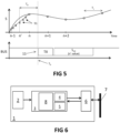
- FIG. 4 an exemplary timing diagram illustrating operation of a sensor device in accordance with embodiments of the present invention is shown.
- the sensor unit may sample signals from a plurality of Hall elements at the predetermined sampling frequency.
- the sensor device 1 comprises a processing unit 3 for receiving the signal S.
- the processing unit 3 comprises a storage memory 4 for storing data derived from the signal S as provided by the sensor unit at at least two points in time.
- the storage memory may for example be RAM (random access memory) embedded in a processor.
- the storage memory may store at least a last sample n and a next to last (i.e. a last but one, a penultimate) sample n-1 of the signal S.
- the sensor device 1 further comprises a bus interface 6 for communicating with an external processor, e.g. an Electronic Control Unit (ECU) via a digital communication bus 7.
- an external processor e.g. an Electronic Control Unit (ECU)
- the digital communication bus may be a serial bus, such as an UART-based communication bus.
- the digital communication bus may be a CAN bus or a CAN-FD bus.
- the bus interface 6 is adapted for receiving a read command from the electronic control unit and for sending, in response to the read command, an estimate S est of the physical quantity to the electronic control unit.
- the ECU may send the read command simply by a state transition 11 of the bus (i.e. a one-to-zero or zero-to-one edge).
- the read command may be a broadcast read command, e.g. a read command which simultaneously targets a plurality of sensor devices connected to the bus.
- the processing unit 3 further comprises an estimator 5 for calculating the estimate of the physical quantity at a reference point in time, which is typically different from any of the at least two points in time (except for possibly rare random alignments), based on the data stored in the storage memory 4.
- the estimate S est may be calculated by an interpolation of the data stored in the storage memory to the reference point in time n', e.g. an interpolation of the signal S n-1 , S n for the at least two points in time.
- interpolation may be a linear interpolation, a quadratic interpolation, a sine interpolation, or other interpolation technique known in the art.
- the estimate S est is calculated by an extrapolation of the data stored in the storage memory to the reference point in time n'.
- the processing unit 3 may for example comprise a timestamp generator and/or a counter, e.g. a counter counting upon receiving a clock signal, to determine a lapsed time between, for example, the acquisition of a most recent sample of the signal S and a time at which the read command is received.
- a timestamp generator and/or a counter e.g. a counter counting upon receiving a clock signal, to determine a lapsed time between, for example, the acquisition of a most recent sample of the signal S and a time at which the read command is received.
- such counter may be configured to reset when a new sample of the signal S is acquired.
- the estimator may be adapted for calculating an interpolated value at each counter update, e.g. updating a stored value that is made available to be supplied as the estimate when the read command is received.
- the interpolated value that is calculated and stored corresponds to a time slot c.f c +(T d -T s ).f c .
- f c time slot c.f c +(T d -T s ).
- the interpolated value may be a linear interpolation between the most recent sample S n and the next-to-last sample S n-1 .
- the updated estimate generated at count value c may be calculated based on the count value c, the predetermined offset T d , the sampling period T s , for example by: S n ⁇ 1 + S n ⁇ S n ⁇ 1 . c/a + T d ⁇ T s . f c .
- Such a timestamp generator and/or counter may provide the relevant timing information to be used by the estimator 5 for calculating the estimate.
- the estimator 5 may be adapted for calculating the estimate upon receiving a request from the bus interface 6, e.g. when the read command has been received.
- the estimator 5 may calculate the value n', in this example by interpolating the sampled values n-1 and n.
- the estimator 5 may continuously or at least frequently update the estimate and making the current estimate available to the bus interface 6 for use when receiving the read command. It is an advantage that this may further reduce the latency of the process, e.g. by ensuring that a value is readily available when the read command is received.
- a plurality of values 51 may be precalculated, e.g. by interpolating between the sampled values n-1 and n, such that the appropriate value n' that corresponds to the reference point in time can be selected upon receiving the read command.
- the reference point in time differs from the point in time To at which the read command is received by a predetermined offset T d , e.g. such that the estimates sent via the bus are always representative of a fixed point in time relative to the read request sent by the ECU.
- the predetermined offset T d may be a predetermined delay such that the reference point in time may lie in the past by a predetermined time interval.
- the estimate may correspond to an estimate of the physical quantity at a predetermined time T 0 -T d before receiving the read command.
- T 0 -T d the value of T 0 -T d is close to zero (zero latency is not required), but it may be more important that the sensor devices provide consistent data "as if they were taken" at approximately the same moment in time ("minimum jitter”).
- the predetermined offset may be substantially zero, such that the estimate corresponds to a current estimate of the physical quantity at the time of receiving the read command, or the predetermined offset may lie in the future, e.g. such that a prediction (or extrapolation) of the physical quantity in the future is provided.
- an estimation such as an extrapolation from the measurements, can be performed that corresponds to a reference point in time To-Td to ensure a substantially constant and substantially predetermined delay.
- the processing unit 3 may comprise a phase-tracking loop unit 8, and/or a phase locked loop unit, for following the physical quantity based on the at least one signal S.
- the storage memory 4 may store at least one parameter of the phase-tracking loop and/or of the phase locked loop. This at least one parameter may be updated regularly (or continuously) to adapt the tracking loop to changes in the signal S.
- the estimator 5 may be adapted for calculating the estimate based on an output of the phase-tracking loop unit and/or the phase locked loop unit, e.g. an output representative of the followed physical quantity.
- the phase-tracking loop unit 8 may comprise an upsampling filter.
- the phase-tracking loop 8 may comprise a sigma-delta modulator.
- the sensor device may be an angular position sensor device, and the sensor unit 2 may comprise a plurality of sensor elements arranged to produce a plurality of signals S 1 ,...,S n each being a function of an input quantity, e.g. an input phase (e.g. representative of a position to be measured) or an input amplitude.
- an input quantity e.g. an input phase (e.g. representative of a position to be measured) or an input amplitude.
- the phase-tracking loop unit 8 may be adapted for generating an error signal by combining the plurality of signals according to an array of weight factors stored in the storage memory, e.g. the at least one parameter stored in the storage memory may comprise the weight factors.
- the phase-tracking loop unit 8 may be adapted for filtering the error signal to generate an output quantity, e.g. an output phase value representative of the position to be measured or output amplitude, as the output of the phase-tracking loop.
- the phase-tracking loop unit 8 may also be adapted for adjusting the array of weight factors based on the output quantity.
- EP 18153346.4 entitled “POSITION SENSING DEVICE” and filed on 25 January 2018, the contents of which are hereby incorporated by reference, discloses a position sensing device for measuring a position.
- the sensor device in accordance with embodiments of the present invention may comprise such position sensing device in accordance with embodiments disclosed in EP 18153346.4 .
- a more detailed overview of such position sensing device can be found in the patent application EP 18153346 .
- a sensor device in accordance with embodiments of the present invention may comprise a plurality of sensors 2 arranged to produce sense signals (S 1 ,...,S k ,...,S n ) each being a function of a physical quantity, the physical quantity being an input phase ⁇ i representative of a position to be measured. While this exemplary embodiment is explained for a input phase representative of a position to be measured and a corresponding output phase, it shall be clear to the skilled person that embodiments of the present invention may relate to a different input quantity and corresponding output quantity, such as, but not limited to, relating to a magnetic field amplitude indicative of a current.
- the sensor device may comprise a combiner circuit 71 arranged to generate an error signal 72 by combining the sense signals according to an array of weight factors, e.g. forming (or comprised in) the at least one parameter of the phase-tracking loop unit 8 stored in the storage memory.
- the sensor device e.g. in the phase-tracking loop unit 8 may comprise a processing block 73 arranged for filtering the error signal and for outputting a phase value ⁇ o representative of the position.
- the sensor device e.g. in the phase-tracking loop unit 8, may comprise a feedback loop comprising a feedback signal unit 74 arranged for receiving the output phase value and for adjusting, based on the received output phase value, the array of weight factors.
- the generalized position to be measured affects the output of at least two sensors 2.
- the resulting sense signals are fed to the combiner circuit, where the signals S k are each multiplied with their corresponding weight factor G k .
- the resulting weighted sum signal 72 next goes to the processing block 73, where it may be filtered in a loop filter 75 and where an estimate of the output phase ⁇ o may be obtained.
- the signal produced by the combiner circuit is a signal representative of the error between the input phase ⁇ i and the estimated output phase ⁇ o.
- the output phase ⁇ o may be fed to a feedback signal unit 74 where a phase-to-weight conversion is performed and updated weight factors are determined for use in the next iteration.
- the processing block may process a combination of the various sense signals at the same time, i.e. in a parallel fashion.
- This processing in parallel may allow for a low position/angle error when the input position/angle changes with high (angular) speed.
- An error estimate may be obtained during each readout time-slot, thus, for the same readout speed, faster than when adopting a sequential approach.
- the sensor signals are combined in the combiner circuit, the different noise contributions of sensors are averaged out, leading to an output with better signal-to-noise (SNR) compared to the SNR of an individual sensing element signals.
- SNR signal-to-noise
- the readout of a sensing element may also comprise averaging and/or combining the outcomes of measurements over different phases, such as is for instance the case when applying spinning current averaging in Hall readout. Such combining/averaging may take place within each time-slot. Each sense signal may then correspond to an averaged/combined value of readouts on a same sensing element. Also in this case, the same conclusion holds that a parallel processing of the thus obtained sense signals allows for better SNR and/or faster error estimates compared to a sequential processing. Furthermore, it is particularly advantageous that an estimate of the physical quantity, e.g. an angle, can be determined based on the output phase ⁇ o (or the estimate may be the output phase). The output phase may be updated at a particularly high frequency, e.g.
- the estimate may be follow the physical quantity at a very high temporal resolution, e.g. such that is is always substantially representative of the reference point in time.
- the present invention in a second aspect, relates to a system 100 comprising a sensor bus 7, a plurality of sensor devices 1 in accordance with embodiments of the first aspect of the present invention connected to the sensor bus and an electronic control unit 81 connected to the sensor bus and configured to generate a broadcast read command BR that simultaneously targets the plurality of sensor devices.
- the system may be used in an automotive environment.
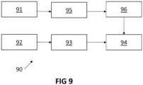
- the present invention relates to a method 90 for communicating sensor data via a digital communication bus.
- the method comprises, in each of a plurality of sensor devices connected to the bus, generating 91 a signal indicative of a physical quantity and storing 95 data derived from the signal as obtained at at least two different points in time.
- the method comprises sending 92 a broadcast read command from an electronic control unit to a plurality of sensor devices via the bus.
- the method comprises, in each of the plurality of sensor devices connected to the bus, receiving 93 the broadcast read command at a point in time, uncorrelated with the at least two points in time, and sending 94, in response to the read command, an estimate of the physical quantity to the electronic control unit.
- the estimate is calculated 96 at a reference point in time based on the stored data.
- the reference point in time differs from the point in time at which the read command is received by substantially a predetermined offset.
- calculating the estimate may comprise executing a phase-tracking loop for tracking the physical quantity and calculating the estimate based on an output of the phase-tracking loop.
Landscapes
- Physics & Mathematics (AREA)
- General Physics & Mathematics (AREA)
- Condensed Matter Physics & Semiconductors (AREA)
- Engineering & Computer Science (AREA)
- Signal Processing (AREA)
- Health & Medical Sciences (AREA)
- Computing Systems (AREA)
- General Health & Medical Sciences (AREA)
- Medical Informatics (AREA)
- Computer Networks & Wireless Communication (AREA)
- Arrangements For Transmission Of Measured Signals (AREA)
- Transmission And Conversion Of Sensor Element Output (AREA)
Claims (9)
- Sensorvorrichtung (1), umfassend:- eine Sensoreinheit (2) zum Erzeugen eines Signals (S), das eine physikalische Größe angibt;- eine Verarbeitungseinheit (3) zum Empfangen des Signals (S), wobei die Verarbeitungseinheit (3) einen Datenspeicher (4) zum Speichern von Daten umfasst, die von dem Signal (S) abgeleitet sind, das von der Sensoreinheit (2) zu mindestens zwei Zeitpunkten bereitgestellt wird, wobei der Speicher angepasst ist zum Speichern mindestens einer letzten Abtastung und einer vorletzten Abtastung des Signals (S), und weiter umfasst eine Schätzeinrichtung (5) zum Berechnen einer Schätzung der physikalischen Größe basierend auf den Daten, die in dem Speicher (4) gespeichert sind; und- eine Busschnittstelle (6) zum Kommunizieren mit einer elektronischen Steuereinheit über einen digitalen Kommunikationsbus (7);wobei die Busschnittstelle (6) ausgelegt ist, zu einem Zeitpunkt (T0), der nicht mit den mindestens zwei Zeitpunkten korreliert, einen Lesebefehl von der elektronischen Steuereinheit zu empfangen und der Schätzeinrichtung (5) ein Anforderungssignal bereitzustellen, wenn der Lesebefehl empfangen wird, und als Reaktion auf den Lesebefehl eine Schätzung der physikalischen Größe über den digitalen Kommunikationsbus (7) an die elektronische Steuereinheit zu senden; undwobei die Schätzeinrichtung (5) dazu ausgelegt ist, die Schätzung der physikalischen Größe zu einem Referenzzeitpunkt (T0-Td), der sich von dem Zeitpunkt (T0), zu dem der Lesebefehl empfangen wird, im Wesentlichen um einen vorbestimmten Versatz (Td) unterscheidet, zu berechnen und wobei die Schätzeinrichtung (5) dazu ausgelegt ist, die Schätzung durch eine Extrapolation der Daten, die in dem Speicher gespeichert sind, zu dem Referenzzeitpunkt zu berechnen.
- Sensorvorrichtung nach Anspruch 1, wobei der Lesebefehl ein Rundsendelesebefehl ist, der gleichzeitig auf eine Vielzahl von Sensorvorrichtungen abzielt, die mit dem digitalen Kommunikationsbus (7) verbunden sind.
- Sensorvorrichtung nach einem der vorstehenden Ansprüche,
wobei die Schätzeinrichtung (5) dazu ausgelegt ist, die Schätzung nach Empfang des Anforderungssignals zu berechnen. - Sensorvorrichtung nach einem der Ansprüche 1 bis 2, wobei die Schätzeinrichtung (5) dazu ausgelegt ist, die Schätzung wiederholt zu aktualisieren und die aktualisierte Schätzung der Busschnittstelle (6) zur Verwendung bei Empfangen des Lesebefehls zur Verfügung zu stellen.
- Sensorvorrichtung nach einem der vorstehenden Ansprüche, wobei die Sensoreinheit (2) dazu ausgelegt ist, die physikalische Größe oder eine andere physikalische Größe, die die physikalische Größe angibt, mit einer vorbestimmten Abtastfrequenz (fs) abzutasten.
- Sensorvorrichtung nach Anspruch 5, wobei die Abtastfrequenz (fs) und der Lesebefehl asynchron sind.
- Sensorvorrichtung nach einem der vorstehenden Ansprüche, wobei die Sensoreinheit (2) dazu ausgelegt ist, eine Vielzahl von Signalen (S1, ..., Sn), die die gleiche physikalische Größe angeben, bereitzustellen.
- System (100), umfassend:einen digitalen Kommunikationsbus (7),eine Vielzahl von Sensorvorrichtungen (1) nach einem der vorstehenden Ansprüche, die mit dem digitalen Kommunikationsbus (7) verbunden sind;eine elektronische Steuereinheit (81), die mit dem digitalen Kommunikationsbus (7) verbunden ist und dazu konfiguriert ist, einen Rundsendelesebefehl zu erzeugen, der gleichzeitig auf die Vielzahl von Sensorvorrichtungen (1) abzielt.
- Verfahren (90) zum Kommunizieren von Sensordaten über einen digitalen Kommunikationsbus (7), wobei das Verfahren umfasst:- Bereitstellen einer Vielzahl von Sensorvorrichtungen, die mit dem digitalen Kommunikationsbus (7) verbunden sind, wobei jede Sensorvorrichtung (1) eine Sensoreinheit (2) zum Erzeugen eines Signals (S), das eine physikalische Größe angibt, und eine Verarbeitungseinheit (3) zum Empfangen des Signals (S) umfasst, wobei die Verarbeitungseinheit (3) einen Datenspeicher (4) zum Speichern von Daten umfasst, die von dem Signal (S) abgeleitet sind, das mindestens zu zwei verschiedenen Zeitpunkten von der Sensoreinheit (2) bereitgestellt wird, wobei der Datenspeicher dazu ausgelegt ist, mindestens eine letzte Abtastung und eine vorletzte Abtastung des Signals (S) zu speichern, und weiter umfassend eine Schätzeinrichtung (5) zum Berechnen einer Schätzung der physikalischen Größe basierend auf den Daten, die in dem Datenspeicher (4) gespeichert sind;- in jeder der Vielzahl von Sensorvorrichtungen, die mit dem digitalen Kommunikationsbus (7) verbunden sind, Erzeugen (91) eines Signals, das eine physikalische Größe angibt, und Speichern von Daten (95), die von dem Signal abgeleitet sind, das mindestens zu zwei verschiedenen Zeitpunkten erhalten wurde;- Senden (92) eines Rundsendelesebefehls von einer elektronischen Steuereinheit zu der Vielzahl von Sensorvorrichtungen (1) über den digitalen Kommunikationsbus (7);- in jeder der Vielzahl von Sensorvorrichtungen (1), die mit dem digitalen Kommunikationsbus (7) verbunden sind, Empfangen (93) des Rundsendelesebefehls zu einem Zeitpunkt (T0), der nicht mit den mindestens zwei Zeitpunkten korreliert, und als Reaktion auf den Lesebefehl Senden (94) einer Schätzung der physikalischen Größe an die elektronische Steuereinheit, wobei die Schätzung berechnet (96) wird durch die Schätzeinrichtung (5) der Sensorvorrichtung (1) der Vielzahl von Sensorvorrichtungen zu einem Referenzzeitpunkt (T0-Td) basierend auf den gespeicherten Daten, und wobei sich der Referenzzeitpunkt von dem Zeitpunkt (T0), zu dem der Lesebefehl empfangen wird, im Wesentlichen um einen vorbestimmten Versatz (Td) unterscheidet, und wobei die Schätzeinrichtung (5) dazu ausgelegt ist, die Schätzung durch eine Extrapolation der Daten, die in dem Speicher gespeichert sind, zu dem Referenzzeitpunkt zu berechnen.
Applications Claiming Priority (1)
| Application Number | Priority Date | Filing Date | Title |
|---|---|---|---|
| EP18197393 | 2018-09-27 |
Publications (3)
| Publication Number | Publication Date |
|---|---|
| EP3629556A1 EP3629556A1 (de) | 2020-04-01 |
| EP3629556B1 EP3629556B1 (de) | 2021-11-03 |
| EP3629556B2 true EP3629556B2 (de) | 2024-07-24 |
Family
ID=63915140
Family Applications (1)
| Application Number | Title | Priority Date | Filing Date |
|---|---|---|---|
| EP19200098.2A Active EP3629556B2 (de) | 2018-09-27 | 2019-09-27 | Sensorvorrichtung, system und entsprechendes verfahren |
Country Status (3)
| Country | Link |
|---|---|
| US (1) | US11162818B2 (de) |
| EP (1) | EP3629556B2 (de) |
| CN (1) | CN110954852B (de) |
Families Citing this family (6)
| Publication number | Priority date | Publication date | Assignee | Title |
|---|---|---|---|---|
| US11209291B2 (en) * | 2019-07-09 | 2021-12-28 | GM Global Technology Operations LLC | Method and apparatus for monitoring a resolver |
| CN112543077B (zh) * | 2020-11-16 | 2022-03-01 | 珠海格力电器股份有限公司 | 能源互联网数据时间处理方法、装置、网关及系统 |
| US12052100B2 (en) * | 2021-02-01 | 2024-07-30 | Semiconductor Components Industries, Llc | DSI3 bus with enhanced robustness |
| CN114252101A (zh) * | 2021-12-21 | 2022-03-29 | 南京英锐创电子科技有限公司 | 标定控制设备、方法及系统 |
| CN116582126B (zh) * | 2023-07-13 | 2023-09-22 | 南京齐芯半导体有限公司 | 一种基于锁相回路的频带搜索方法 |
| DE102023212276A1 (de) * | 2023-12-06 | 2025-06-12 | Robert Bosch Gesellschaft mit beschränkter Haftung | System und Verfahren zum Synchronisieren mittels Lesezugriff |
Citations (1)
| Publication number | Priority date | Publication date | Assignee | Title |
|---|---|---|---|---|
| US20160282116A1 (en) † | 2015-03-23 | 2016-09-29 | Seiko Epson Corporation | Data processing circuit, physical quantity detection circuit, physical quantity detection device, electronic apparatus, and moving object |
Family Cites Families (14)
| Publication number | Priority date | Publication date | Assignee | Title |
|---|---|---|---|---|
| WO2008111436A1 (ja) * | 2007-03-05 | 2008-09-18 | Yokohama National University | 自動車のピッチング制御装置および制御方法 |
| KR100889961B1 (ko) * | 2007-04-30 | 2009-03-24 | (주)컨벡스 | 스텝 모터 위치 오차 보정 방법 및 시스템 |
| JP5288214B2 (ja) * | 2007-12-18 | 2013-09-11 | ソニー株式会社 | データ処理装置、データ処理方法、及びプログラム |
| US8442134B2 (en) * | 2008-01-22 | 2013-05-14 | Nxp B.V. | Post DFT/FFT time tracking algorithm for OFDM receivers |
| DE102012203664A1 (de) * | 2012-03-08 | 2013-09-12 | Robert Bosch Gmbh | Verfahren zur Nachführung eines Frequenzsignals und korrespondierende Sensoreinheit für ein Fahrzeug |
| US9411756B2 (en) * | 2012-06-18 | 2016-08-09 | Blackberry Limited | Function approximation circuitry |
| JP2014048697A (ja) * | 2012-08-29 | 2014-03-17 | Hitachi Ltd | 設備状態監視方法及び設備状態監視装置 |
| JP2016212066A (ja) | 2015-05-13 | 2016-12-15 | 富士通株式会社 | 移動体端末、センサ値補間方法、センサ値補間プログラム、行動認識装置および行動認識システム |
| JP6361589B2 (ja) * | 2015-06-11 | 2018-07-25 | 株式会社デンソー | 通信システム |
| US9605981B1 (en) * | 2015-09-22 | 2017-03-28 | Mitsubishi Electric Corporation | Absolute encoder |
| US10079650B2 (en) * | 2015-12-04 | 2018-09-18 | Infineon Technologies Ag | Robust high speed sensor interface for remote sensors |
| US9837990B1 (en) * | 2015-12-11 | 2017-12-05 | Syntropy Systems, Llc | Digital signal processor |
| US10948515B2 (en) * | 2016-12-09 | 2021-03-16 | InvenSease, Inc. | Data correction for a sensor |
| EP3517897B1 (de) | 2018-01-25 | 2020-10-28 | Melexis Technologies SA | Positionserfassungsvorrichtung |
-
2019
- 2019-09-26 CN CN201910918624.4A patent/CN110954852B/zh active Active
- 2019-09-27 US US16/585,187 patent/US11162818B2/en active Active
- 2019-09-27 EP EP19200098.2A patent/EP3629556B2/de active Active
Patent Citations (1)
| Publication number | Priority date | Publication date | Assignee | Title |
|---|---|---|---|---|
| US20160282116A1 (en) † | 2015-03-23 | 2016-09-29 | Seiko Epson Corporation | Data processing circuit, physical quantity detection circuit, physical quantity detection device, electronic apparatus, and moving object |
Non-Patent Citations (1)
| Title |
|---|
| INFINEON: "Data Sheet TLE 5012B GMR-Based Angle Sensor", 20 June 2018 (2018-06-20), pages 1 - 51, XP055950426 † |
Also Published As
| Publication number | Publication date |
|---|---|
| EP3629556A1 (de) | 2020-04-01 |
| CN110954852A (zh) | 2020-04-03 |
| US11162818B2 (en) | 2021-11-02 |
| EP3629556B1 (de) | 2021-11-03 |
| CN110954852B (zh) | 2022-05-17 |
| US20200103254A1 (en) | 2020-04-02 |
Similar Documents
| Publication | Publication Date | Title |
|---|---|---|
| EP3629556B2 (de) | Sensorvorrichtung, system und entsprechendes verfahren | |
| KR102330624B1 (ko) | 고속 센서 인터페이스를 위한 동기화 메커니즘 | |
| WO2019215473A1 (en) | Multisensor data fusion systems and methods | |
| EP2965458B1 (de) | Schaltung zur erzeugung schwankender abtastung von serieller datenübertragung | |
| TWI598571B (zh) | 感測器及感測器融合系統及用於將資料樣本的相位置及/或週期調整的方法 | |
| EP2533011B1 (de) | Gyroskopdynamischer Motoramplitudenausgleich für eine verbesserte Ratenschätzung während des Startens | |
| US10033390B2 (en) | Systems and methods for clock synchronization in a data acquisition system | |
| EP3525079A1 (de) | Leistungsarme synchronisation mehrerer analog-digital-wandler | |
| CN103983296B (zh) | 用于检测测量值的方法及装置 | |
| CN1020143C (zh) | 数字数据通信系统时序恢复的方法和装置 | |
| US20220321318A1 (en) | Sensor device and related method and system | |
| US10805183B2 (en) | Method and apparatus for sampling rate conversion of a stream of samples | |
| JP5166869B2 (ja) | クロックジッターの測定 | |
| US20130346022A1 (en) | Physical quantity measuring apparatus and physical quantity measuring method | |
| US12212648B2 (en) | Sensor device and related method and system | |
| EP3160077A1 (de) | Taktrückgewinnungsvorrichtung und verfahren zur taktrückgewinnung | |
| US7827377B2 (en) | Method for reading out sensor data | |
| CN114097010B (zh) | 信息处理装置、计算机能读取的记录介质和信息处理方法 | |
| EP3679645B1 (de) | Verfahren zur steuerung eines bürstenlosen wechselstrommotors | |
| CN110487304B (zh) | 位置感测设备 | |
| US12492922B2 (en) | Apparatuses and methods for comparing redundant signals in functional safe systems | |
| GB2552295A (en) | Signal processing | |
| JPS62163911A (ja) | 位置,速度検出方法 | |
| Sandee et al. | Implementing control algorithms on embedded platforms |
Legal Events
| Date | Code | Title | Description |
|---|---|---|---|
| PUAI | Public reference made under article 153(3) epc to a published international application that has entered the european phase |
Free format text: ORIGINAL CODE: 0009012 |
|
| STAA | Information on the status of an ep patent application or granted ep patent |
Free format text: STATUS: THE APPLICATION HAS BEEN PUBLISHED |
|
| AK | Designated contracting states |
Kind code of ref document: A1 Designated state(s): AL AT BE BG CH CY CZ DE DK EE ES FI FR GB GR HR HU IE IS IT LI LT LU LV MC MK MT NL NO PL PT RO RS SE SI SK SM TR |
|
| AX | Request for extension of the european patent |
Extension state: BA ME |
|
| STAA | Information on the status of an ep patent application or granted ep patent |
Free format text: STATUS: REQUEST FOR EXAMINATION WAS MADE |
|
| 17P | Request for examination filed |
Effective date: 20200918 |
|
| RBV | Designated contracting states (corrected) |
Designated state(s): AL AT BE BG CH CY CZ DE DK EE ES FI FR GB GR HR HU IE IS IT LI LT LU LV MC MK MT NL NO PL PT RO RS SE SI SK SM TR |
|
| RIC1 | Information provided on ipc code assigned before grant |
Ipc: H04L 29/08 20060101AFI20210528BHEP |
|
| GRAP | Despatch of communication of intention to grant a patent |
Free format text: ORIGINAL CODE: EPIDOSNIGR1 |
|
| STAA | Information on the status of an ep patent application or granted ep patent |
Free format text: STATUS: GRANT OF PATENT IS INTENDED |
|
| GRAJ | Information related to disapproval of communication of intention to grant by the applicant or resumption of examination proceedings by the epo deleted |
Free format text: ORIGINAL CODE: EPIDOSDIGR1 |
|
| STAA | Information on the status of an ep patent application or granted ep patent |
Free format text: STATUS: REQUEST FOR EXAMINATION WAS MADE |
|
| INTG | Intention to grant announced |
Effective date: 20210712 |
|
| INTC | Intention to grant announced (deleted) | ||
| GRAP | Despatch of communication of intention to grant a patent |
Free format text: ORIGINAL CODE: EPIDOSNIGR1 |
|
| STAA | Information on the status of an ep patent application or granted ep patent |
Free format text: STATUS: GRANT OF PATENT IS INTENDED |
|
| GRAS | Grant fee paid |
Free format text: ORIGINAL CODE: EPIDOSNIGR3 |
|
| GRAA | (expected) grant |
Free format text: ORIGINAL CODE: 0009210 |
|
| STAA | Information on the status of an ep patent application or granted ep patent |
Free format text: STATUS: THE PATENT HAS BEEN GRANTED |
|
| INTG | Intention to grant announced |
Effective date: 20210906 |
|
| AK | Designated contracting states |
Kind code of ref document: B1 Designated state(s): AL AT BE BG CH CY CZ DE DK EE ES FI FR GB GR HR HU IE IS IT LI LT LU LV MC MK MT NL NO PL PT RO RS SE SI SK SM TR |
|
| REG | Reference to a national code |
Ref country code: GB Ref legal event code: FG4D |
|
| REG | Reference to a national code |
Ref country code: AT Ref legal event code: REF Ref document number: 1445027 Country of ref document: AT Kind code of ref document: T Effective date: 20211115 Ref country code: CH Ref legal event code: EP |
|
| REG | Reference to a national code |
Ref country code: IE Ref legal event code: FG4D |
|
| REG | Reference to a national code |
Ref country code: DE Ref legal event code: R096 Ref document number: 602019008911 Country of ref document: DE |
|
| REG | Reference to a national code |
Ref country code: DE Ref legal event code: R079 Ref document number: 602019008911 Country of ref document: DE Free format text: PREVIOUS MAIN CLASS: H04L0029080000 Ipc: H04L0065000000 |
|
| REG | Reference to a national code |
Ref country code: LT Ref legal event code: MG9D |
|
| REG | Reference to a national code |
Ref country code: NL Ref legal event code: MP Effective date: 20211103 |
|
| REG | Reference to a national code |
Ref country code: AT Ref legal event code: MK05 Ref document number: 1445027 Country of ref document: AT Kind code of ref document: T Effective date: 20211103 |
|
| PG25 | Lapsed in a contracting state [announced via postgrant information from national office to epo] |
Ref country code: RS Free format text: LAPSE BECAUSE OF FAILURE TO SUBMIT A TRANSLATION OF THE DESCRIPTION OR TO PAY THE FEE WITHIN THE PRESCRIBED TIME-LIMIT Effective date: 20211103 Ref country code: LT Free format text: LAPSE BECAUSE OF FAILURE TO SUBMIT A TRANSLATION OF THE DESCRIPTION OR TO PAY THE FEE WITHIN THE PRESCRIBED TIME-LIMIT Effective date: 20211103 Ref country code: FI Free format text: LAPSE BECAUSE OF FAILURE TO SUBMIT A TRANSLATION OF THE DESCRIPTION OR TO PAY THE FEE WITHIN THE PRESCRIBED TIME-LIMIT Effective date: 20211103 Ref country code: BG Free format text: LAPSE BECAUSE OF FAILURE TO SUBMIT A TRANSLATION OF THE DESCRIPTION OR TO PAY THE FEE WITHIN THE PRESCRIBED TIME-LIMIT Effective date: 20220203 Ref country code: AT Free format text: LAPSE BECAUSE OF FAILURE TO SUBMIT A TRANSLATION OF THE DESCRIPTION OR TO PAY THE FEE WITHIN THE PRESCRIBED TIME-LIMIT Effective date: 20211103 |
|
| PG25 | Lapsed in a contracting state [announced via postgrant information from national office to epo] |
Ref country code: IS Free format text: LAPSE BECAUSE OF FAILURE TO SUBMIT A TRANSLATION OF THE DESCRIPTION OR TO PAY THE FEE WITHIN THE PRESCRIBED TIME-LIMIT Effective date: 20220303 Ref country code: SE Free format text: LAPSE BECAUSE OF FAILURE TO SUBMIT A TRANSLATION OF THE DESCRIPTION OR TO PAY THE FEE WITHIN THE PRESCRIBED TIME-LIMIT Effective date: 20211103 Ref country code: PT Free format text: LAPSE BECAUSE OF FAILURE TO SUBMIT A TRANSLATION OF THE DESCRIPTION OR TO PAY THE FEE WITHIN THE PRESCRIBED TIME-LIMIT Effective date: 20220303 Ref country code: PL Free format text: LAPSE BECAUSE OF FAILURE TO SUBMIT A TRANSLATION OF THE DESCRIPTION OR TO PAY THE FEE WITHIN THE PRESCRIBED TIME-LIMIT Effective date: 20211103 Ref country code: NO Free format text: LAPSE BECAUSE OF FAILURE TO SUBMIT A TRANSLATION OF THE DESCRIPTION OR TO PAY THE FEE WITHIN THE PRESCRIBED TIME-LIMIT Effective date: 20220203 Ref country code: NL Free format text: LAPSE BECAUSE OF FAILURE TO SUBMIT A TRANSLATION OF THE DESCRIPTION OR TO PAY THE FEE WITHIN THE PRESCRIBED TIME-LIMIT Effective date: 20211103 Ref country code: LV Free format text: LAPSE BECAUSE OF FAILURE TO SUBMIT A TRANSLATION OF THE DESCRIPTION OR TO PAY THE FEE WITHIN THE PRESCRIBED TIME-LIMIT Effective date: 20211103 Ref country code: HR Free format text: LAPSE BECAUSE OF FAILURE TO SUBMIT A TRANSLATION OF THE DESCRIPTION OR TO PAY THE FEE WITHIN THE PRESCRIBED TIME-LIMIT Effective date: 20211103 Ref country code: GR Free format text: LAPSE BECAUSE OF FAILURE TO SUBMIT A TRANSLATION OF THE DESCRIPTION OR TO PAY THE FEE WITHIN THE PRESCRIBED TIME-LIMIT Effective date: 20220204 Ref country code: ES Free format text: LAPSE BECAUSE OF FAILURE TO SUBMIT A TRANSLATION OF THE DESCRIPTION OR TO PAY THE FEE WITHIN THE PRESCRIBED TIME-LIMIT Effective date: 20211103 |
|
| PG25 | Lapsed in a contracting state [announced via postgrant information from national office to epo] |
Ref country code: SM Free format text: LAPSE BECAUSE OF FAILURE TO SUBMIT A TRANSLATION OF THE DESCRIPTION OR TO PAY THE FEE WITHIN THE PRESCRIBED TIME-LIMIT Effective date: 20211103 Ref country code: SK Free format text: LAPSE BECAUSE OF FAILURE TO SUBMIT A TRANSLATION OF THE DESCRIPTION OR TO PAY THE FEE WITHIN THE PRESCRIBED TIME-LIMIT Effective date: 20211103 Ref country code: RO Free format text: LAPSE BECAUSE OF FAILURE TO SUBMIT A TRANSLATION OF THE DESCRIPTION OR TO PAY THE FEE WITHIN THE PRESCRIBED TIME-LIMIT Effective date: 20211103 Ref country code: EE Free format text: LAPSE BECAUSE OF FAILURE TO SUBMIT A TRANSLATION OF THE DESCRIPTION OR TO PAY THE FEE WITHIN THE PRESCRIBED TIME-LIMIT Effective date: 20211103 Ref country code: DK Free format text: LAPSE BECAUSE OF FAILURE TO SUBMIT A TRANSLATION OF THE DESCRIPTION OR TO PAY THE FEE WITHIN THE PRESCRIBED TIME-LIMIT Effective date: 20211103 Ref country code: CZ Free format text: LAPSE BECAUSE OF FAILURE TO SUBMIT A TRANSLATION OF THE DESCRIPTION OR TO PAY THE FEE WITHIN THE PRESCRIBED TIME-LIMIT Effective date: 20211103 |
|
| REG | Reference to a national code |
Ref country code: DE Ref legal event code: R026 Ref document number: 602019008911 Country of ref document: DE |
|
| PLBI | Opposition filed |
Free format text: ORIGINAL CODE: 0009260 |
|
| PLAX | Notice of opposition and request to file observation + time limit sent |
Free format text: ORIGINAL CODE: EPIDOSNOBS2 |
|
| 26 | Opposition filed |
Opponent name: MOLNIA, DAVID Effective date: 20220802 |
|
| PG25 | Lapsed in a contracting state [announced via postgrant information from national office to epo] |
Ref country code: AL Free format text: LAPSE BECAUSE OF FAILURE TO SUBMIT A TRANSLATION OF THE DESCRIPTION OR TO PAY THE FEE WITHIN THE PRESCRIBED TIME-LIMIT Effective date: 20211103 |
|
| PG25 | Lapsed in a contracting state [announced via postgrant information from national office to epo] |
Ref country code: SI Free format text: LAPSE BECAUSE OF FAILURE TO SUBMIT A TRANSLATION OF THE DESCRIPTION OR TO PAY THE FEE WITHIN THE PRESCRIBED TIME-LIMIT Effective date: 20211103 |
|
| PLAF | Information modified related to communication of a notice of opposition and request to file observations + time limit |
Free format text: ORIGINAL CODE: EPIDOSCOBS2 |
|
| PLBB | Reply of patent proprietor to notice(s) of opposition received |
Free format text: ORIGINAL CODE: EPIDOSNOBS3 |
|
| PG25 | Lapsed in a contracting state [announced via postgrant information from national office to epo] |
Ref country code: MC Free format text: LAPSE BECAUSE OF FAILURE TO SUBMIT A TRANSLATION OF THE DESCRIPTION OR TO PAY THE FEE WITHIN THE PRESCRIBED TIME-LIMIT Effective date: 20211103 |
|
| REG | Reference to a national code |
Ref country code: CH Ref legal event code: PL |
|
| REG | Reference to a national code |
Ref country code: BE Ref legal event code: MM Effective date: 20220930 |
|
| PG25 | Lapsed in a contracting state [announced via postgrant information from national office to epo] |
Ref country code: IT Free format text: LAPSE BECAUSE OF FAILURE TO SUBMIT A TRANSLATION OF THE DESCRIPTION OR TO PAY THE FEE WITHIN THE PRESCRIBED TIME-LIMIT Effective date: 20211103 |
|
| P01 | Opt-out of the competence of the unified patent court (upc) registered |
Effective date: 20230517 |
|
| PG25 | Lapsed in a contracting state [announced via postgrant information from national office to epo] |
Ref country code: LU Free format text: LAPSE BECAUSE OF NON-PAYMENT OF DUE FEES Effective date: 20220927 |
|
| PG25 | Lapsed in a contracting state [announced via postgrant information from national office to epo] |
Ref country code: LI Free format text: LAPSE BECAUSE OF NON-PAYMENT OF DUE FEES Effective date: 20220930 Ref country code: IE Free format text: LAPSE BECAUSE OF NON-PAYMENT OF DUE FEES Effective date: 20220927 Ref country code: CH Free format text: LAPSE BECAUSE OF NON-PAYMENT OF DUE FEES Effective date: 20220930 |
|
| PG25 | Lapsed in a contracting state [announced via postgrant information from national office to epo] |
Ref country code: BE Free format text: LAPSE BECAUSE OF NON-PAYMENT OF DUE FEES Effective date: 20220930 |
|
| PG25 | Lapsed in a contracting state [announced via postgrant information from national office to epo] |
Ref country code: HU Free format text: LAPSE BECAUSE OF FAILURE TO SUBMIT A TRANSLATION OF THE DESCRIPTION OR TO PAY THE FEE WITHIN THE PRESCRIBED TIME-LIMIT; INVALID AB INITIO Effective date: 20190927 |
|
| PG25 | Lapsed in a contracting state [announced via postgrant information from national office to epo] |
Ref country code: CY Free format text: LAPSE BECAUSE OF FAILURE TO SUBMIT A TRANSLATION OF THE DESCRIPTION OR TO PAY THE FEE WITHIN THE PRESCRIBED TIME-LIMIT Effective date: 20211103 |
|
| GBPC | Gb: european patent ceased through non-payment of renewal fee |
Effective date: 20230927 |
|
| PG25 | Lapsed in a contracting state [announced via postgrant information from national office to epo] |
Ref country code: MK Free format text: LAPSE BECAUSE OF FAILURE TO SUBMIT A TRANSLATION OF THE DESCRIPTION OR TO PAY THE FEE WITHIN THE PRESCRIBED TIME-LIMIT Effective date: 20211103 |
|
| PUAH | Patent maintained in amended form |
Free format text: ORIGINAL CODE: 0009272 |
|
| STAA | Information on the status of an ep patent application or granted ep patent |
Free format text: STATUS: PATENT MAINTAINED AS AMENDED |
|
| PG25 | Lapsed in a contracting state [announced via postgrant information from national office to epo] |
Ref country code: GB Free format text: LAPSE BECAUSE OF NON-PAYMENT OF DUE FEES Effective date: 20230927 |
|
| 27A | Patent maintained in amended form |
Effective date: 20240724 |
|
| AK | Designated contracting states |
Kind code of ref document: B2 Designated state(s): AL AT BE BG CH CY CZ DE DK EE ES FI FR GB GR HR HU IE IS IT LI LT LU LV MC MK MT NL NO PL PT RO RS SE SI SK SM TR |
|
| REG | Reference to a national code |
Ref country code: DE Ref legal event code: R102 Ref document number: 602019008911 Country of ref document: DE |
|
| PG25 | Lapsed in a contracting state [announced via postgrant information from national office to epo] |
Ref country code: GB Free format text: LAPSE BECAUSE OF NON-PAYMENT OF DUE FEES Effective date: 20230927 |
|
| PG25 | Lapsed in a contracting state [announced via postgrant information from national office to epo] |
Ref country code: MT Free format text: LAPSE BECAUSE OF FAILURE TO SUBMIT A TRANSLATION OF THE DESCRIPTION OR TO PAY THE FEE WITHIN THE PRESCRIBED TIME-LIMIT Effective date: 20211103 |
|
| PGFP | Annual fee paid to national office [announced via postgrant information from national office to epo] |
Ref country code: DE Payment date: 20250820 Year of fee payment: 7 |
|
| PGFP | Annual fee paid to national office [announced via postgrant information from national office to epo] |
Ref country code: FR Payment date: 20250821 Year of fee payment: 7 |
|
| PG25 | Lapsed in a contracting state [announced via postgrant information from national office to epo] |
Ref country code: TR Free format text: LAPSE BECAUSE OF FAILURE TO SUBMIT A TRANSLATION OF THE DESCRIPTION OR TO PAY THE FEE WITHIN THE PRESCRIBED TIME-LIMIT Effective date: 20211103 |