EP3629426A1 - Seal member and connector assembly - Google Patents
Seal member and connector assembly Download PDFInfo
- Publication number
- EP3629426A1 EP3629426A1 EP19199199.1A EP19199199A EP3629426A1 EP 3629426 A1 EP3629426 A1 EP 3629426A1 EP 19199199 A EP19199199 A EP 19199199A EP 3629426 A1 EP3629426 A1 EP 3629426A1
- Authority
- EP
- European Patent Office
- Prior art keywords
- seal member
- body portion
- main body
- flange portion
- member according
- Prior art date
- Legal status (The legal status is an assumption and is not a legal conclusion. Google has not performed a legal analysis and makes no representation as to the accuracy of the status listed.)
- Withdrawn
Links
- 230000003014 reinforcing effect Effects 0.000 claims description 14
- 238000005452 bending Methods 0.000 claims description 7
- 238000006243 chemical reaction Methods 0.000 abstract description 44
- 238000006073 displacement reaction Methods 0.000 description 11
- 230000002093 peripheral effect Effects 0.000 description 9
- 230000006835 compression Effects 0.000 description 6
- 238000007906 compression Methods 0.000 description 6
- 239000000463 material Substances 0.000 description 5
- 230000007423 decrease Effects 0.000 description 4
- 230000005489 elastic deformation Effects 0.000 description 4
- 230000000694 effects Effects 0.000 description 3
- 238000001746 injection moulding Methods 0.000 description 3
- 239000007788 liquid Substances 0.000 description 3
- 230000013011 mating Effects 0.000 description 2
- 239000007769 metal material Substances 0.000 description 2
- 239000011347 resin Substances 0.000 description 2
- 229920005989 resin Polymers 0.000 description 2
- 229910000838 Al alloy Inorganic materials 0.000 description 1
- 229910000881 Cu alloy Inorganic materials 0.000 description 1
- 230000015572 biosynthetic process Effects 0.000 description 1
- 230000008030 elimination Effects 0.000 description 1
- 238000003379 elimination reaction Methods 0.000 description 1
- 238000000605 extraction Methods 0.000 description 1
- 238000003780 insertion Methods 0.000 description 1
- 230000037431 insertion Effects 0.000 description 1
- -1 polybutylene terephthalate Polymers 0.000 description 1
- 229920001707 polybutylene terephthalate Polymers 0.000 description 1
- 239000007787 solid Substances 0.000 description 1
- 239000000243 solution Substances 0.000 description 1
- XLYOFNOQVPJJNP-UHFFFAOYSA-N water Substances O XLYOFNOQVPJJNP-UHFFFAOYSA-N 0.000 description 1
Images






Classifications
-
- H—ELECTRICITY
- H01—ELECTRIC ELEMENTS
- H01R—ELECTRICALLY-CONDUCTIVE CONNECTIONS; STRUCTURAL ASSOCIATIONS OF A PLURALITY OF MUTUALLY-INSULATED ELECTRICAL CONNECTING ELEMENTS; COUPLING DEVICES; CURRENT COLLECTORS
- H01R13/00—Details of coupling devices of the kinds covered by groups H01R12/70 or H01R24/00 - H01R33/00
- H01R13/46—Bases; Cases
- H01R13/52—Dustproof, splashproof, drip-proof, waterproof, or flameproof cases
-
- H—ELECTRICITY
- H01—ELECTRIC ELEMENTS
- H01R—ELECTRICALLY-CONDUCTIVE CONNECTIONS; STRUCTURAL ASSOCIATIONS OF A PLURALITY OF MUTUALLY-INSULATED ELECTRICAL CONNECTING ELEMENTS; COUPLING DEVICES; CURRENT COLLECTORS
- H01R13/00—Details of coupling devices of the kinds covered by groups H01R12/70 or H01R24/00 - H01R33/00
- H01R13/46—Bases; Cases
- H01R13/52—Dustproof, splashproof, drip-proof, waterproof, or flameproof cases
- H01R13/5202—Sealing means between parts of housing or between housing part and a wall, e.g. sealing rings
-
- H—ELECTRICITY
- H01—ELECTRIC ELEMENTS
- H01R—ELECTRICALLY-CONDUCTIVE CONNECTIONS; STRUCTURAL ASSOCIATIONS OF A PLURALITY OF MUTUALLY-INSULATED ELECTRICAL CONNECTING ELEMENTS; COUPLING DEVICES; CURRENT COLLECTORS
- H01R13/00—Details of coupling devices of the kinds covered by groups H01R12/70 or H01R24/00 - H01R33/00
- H01R13/46—Bases; Cases
- H01R13/52—Dustproof, splashproof, drip-proof, waterproof, or flameproof cases
- H01R13/5205—Sealing means between cable and housing, e.g. grommet
Definitions
- the present invention relates to a seal member suitable for use in an electrical connector and/or another electronic component.
- a seal member When an electrical connector is attached to a case of electronic equipment, a seal member is sometimes disposed between the electrical connector and the case in order to prevent liquid ingress into the electronic equipment.
- a seal member of this type a configuration is known that has a lip formed along an extension direction of the seal member and brings the lip into close contact with a contacted component, thereby improving waterproofness (for example, JPH8-315904A).
- a configuration of a grommet is known that has coaxially-positioned inner and outer cylindrical portions linked by means of a rib and elastically deforms the outer cylindrical portion in a reduction direction of the diameter thereof, thereby facilitating attachment to a hole provided in a panel (for example, JP2005-229711A ).
- a seal member that elastically deforms or is configured to elastically deform under a compressive load includes: a main body portion; a deformable part body portion or an easily-deformable portion formed integrally with the main body portion and being more easily deformable than the main body portion; and a pair of lip portions formed on one face side of the seal member in a loading direction in which the compressive load acts.
- the compressive load acting on the pair of lip portions acts on the easily-deformable portion.
- the easily-deformable portion may have a first flange portion protruding from a side face of the main body portion on one face side of the main body portion.
- the first flange portion may be so formed as to be thinner in dimension in the loading direction than the main body portion.
- Vertices of the pair of lip portions in cross-section may be located more externally than the main body portion.
- An interval or spacing between the vertices of the pair of lip portions which may be in cross-section may be set larger than a width of the main body portion. The width of the main body portion may be within the interval between the vertices of the pair of lip portions.
- the easily-deformable portion may further have a second flange portion protruding from a side face of the main body portion on another face side of the main body portion.
- the seal member may further include a rib connected to the first flange portion and the second flange portion.
- the seal member has a U-like overall shape or a substantially U-shape.
- a connector assembly of the present invention includes: an electrical connector; and the above-described seal member attached to the electrical connector.
- a seal member that elastically deforms or is configured to elastically deform under a compressive load includes: a main body portion; a deformable part body portion or an easily-deformable portion formed integrally with the main body portion and being more easily deformable than the main body portion; and a plurality of reinforcing portions being more easily deformable than the easily-deformable portion and supporting the easily-deformable portion.
- the seal member may include any of the features described above.
- the easily-deformable portion deforms ahead of the main body portion until the deformation of the easily-deformable portion reaches the limit after the seal member comes into contact with a contacted component. Since the easily-deformable portion of the seal member easily deforms, a reaction force exerted in the seal member is small. Therefore, a force required for the work of attaching the connector assembly to a case can be reduced. On the other hand, once the deformation of the easily-deformable portion reaches the limit, the main body portion undergoes elastic deformation in place of the easily-deformable portion and exerts the reaction force. Since being not easily elastically deformable, the main body portion exerts a larger reaction force than the easily-deformable portion does. Thereby, the waterproof performance of the seal member can be ensured.
- the reaction force of the seal member can be compensated by the reinforcing portions. Since being more easily deformable than the easily-deformable portion, the reinforcing portions do not obstruct the deformation of the easily-deformable portion. In addition, fine adjustment of the magnitude of the reaction force exerted in the seal member can also be made by means of the shape and dimensions of the reinforcing portions.
- the lip portions and the easily-deformable portion deform ahead of the main body portion until the deformation of the easily-deformable portion reaches the limit after the lip portions come into contact with a contacted component. Since the lip portions and the easily-deformable portion of the seal member are easily deformable, a reaction force exerted in the seal member is small. Therefore, a force required for the work of attaching the connector assembly to a case can be reduced.
- the main body portion undergoes elastic deformation in place of the lip portions and the easily-deformable portion and exerts the reaction force. Since not being easily elastically deformable, the main body portion exerts a larger reaction force than the lip portions or the like do. Thereby, waterproof performance of the seal member can be ensured.
- a seal member 10 of the present embodiment is used to prevent water ingress between an electrical connector 30 (see Figure 4 ) and a case 50 of an electronic equipment (see Figures 6A and 6B ). It should be noted that a width direction X, a height direction Y and a thickness direction Z of each element of the present embodiment are defined as shown in the drawings.
- the seal member 10 as shown in Figure 4 , Figures 5A and 5B , and Figures 6A and 6B , is attached over a side face portion 30a and a bottom face portion 30b of the electrical connector 30. Furthermore, as shown in Figure 6B , the seal member 10 is disposed between the case 50 and the electrical connector 30 when the electrical connector 30 is attached to the case 50 of the electronic equipment.
- the seal member 10 of the present embodiment is, for example, a rubber member integrally formed by injection molding.
- the overall shape of the seal member 10, as shown in Figures 1A and 1B is a U-like shape opened on the upper side in the drawings.
- the seal member 10 as shown in Figure 2 , has a main body portion 11, a pair of first flange portions 12, a pair of second flange portions 13, a pair of projecting rim portions 14, and a pair of lip portions 15.
- the first flange portions 12 are so formed on an outer peripheral side of the main body portion 11 (the lower side of Figure 2 ) as to protrude from both side faces, respectively, of the main body portion 11.
- the second flange portions 13 are so formed on an inner peripheral side of the main body portion 11 (the upper side of Figure 2 ) as to protrude from both side faces, respectively, of the main body portion 11.
- the first flange portion 12 and the second flange portion 13 are provided with a groove 17 therebetween, and are thereby set smaller in dimension in the height direction Y than the main body portion 11. That is, the first flange portion 12 and the second flange portion 13 are connected like a cantilever to the main body portion 11. Therefore, the first flange portion 12 and the second flange portion 13 are one example of an easily-deformable portion that deforms easily under a load in the height direction Y.
- the main body portion 11 connects the first flange portion 12 on the outer peripheral side and the second flange portion 13 on the inner peripheral side vertically in the drawing.
- a portion composed of the main body portion 11, the first flange portion 12 and the second flange portion 13 has a substantially H-like shape rotated by 90 degrees in cross-section.
- the main body portion 11 is larger in dimension in the height direction Y than the first flange portion 12 and the second flange portion 13. Therefore, in the main body portion 11, for example, the deformation amount in compression direction is minute under substantially the same load in the height direction Y as the first flange portion 12 and the second flange portion 13.
- the projecting rim portions 14 are connected to both sides, respectively, of the second flange portions 13.
- receiving holes 14a and slits 14b are formed in the projecting rim portion 14, as shown in Figure 1B .
- the receiving hole 14a and the slit 14b engage with a pin 35 and a projection 36, respectively, provided on the electrical connector 30, and function to align the seal member 10 with the electrical connector 30.
- FIG. 1B in a pair of arm portions 10a curved and extending in the height direction Y from both ends of a bottom portion 10b of the seal member 10, supporting walls 14c are formed from the respective projecting rim portions 14 in a direction toward the inner periphery.
- An engaging recess 16 having a C-like shape in cross-section is formed in an inner peripheral face of the seal member 10. This engaging recess 16 faces the supporting walls 14c and the main body portion 11 in the arm portion 10a of the seal member 10, and faces the projecting rim portions 14 and the main body portion 11 in the bottom portion 10b of the seal member 10.
- An engaging protrusion 34 (see Figure 8 ), described later, provided on an outer periphery of the electrical connector 30 is engaged in the engaging recess 16.
- a guiding groove 14d extending along the height direction Y is formed in an outer face of the supporting wall 14c, as shown in Figures 1A and 1B and Figure 4 .
- the guiding groove 14d engages with a key, not shown, provided on the electrical connector 30.
- the guiding groove 14d guides the seal member 10 in the height direction Y that is an insertion/extraction direction when the seal member 10 is attached to the electrical connector 30, and also functions as a retainer so that the seal member 10 will not become detached in the width direction X from the electrical connector 30.
- the first flange portion 12 and the second flange portion 13 extend substantially parallel along the thickness direction Z, and protrude in the thickness direction Z more than the main body portion 11 from both the side faces of the main body portion 11. Therefore, the groove 17 facing the first flange portion 12, the second flange portion 13 and the main body portion 11 and recessed in the thickness direction Z is formed in both side faces of the seal member 10.
- An example of the groove 17 that is formed in a substantially V-like shape in cross-section is shown in Figure 2 .
- the cross-section of the groove 17 may have another shape, for example, a C-like shape, a U-like shape, a semicircular shape, or the like.
- the seal member 10 When the bottom portion 10b of the seal member 10 is compressed in the height direction Y, the seal member 10 deforms such that the first flange portion 12 and the second flange portion 13 deflect toward the inside of the groove 17 to narrow the space of the groove 17 in the height direction Y. At this time, with the compression of the main body portion 11, a reaction force occurs in the height direction Y.
- the compression direction is from the inner peripheral side of the seal member 10 toward the outer peripheral side thereof, and the seal member 10 is compressed to deform in the same manner as the bottom portion 10b. Therefore, in the arm portion 10a, the compression direction is not coincident with the height direction Y.
- the compression of the seal member 10 the case of the bottom portion 10b will be described unless otherwise noted.
- the groove 17 is formed along an extension direction of the seal member 10 from one end to another end of the seal member 10.
- a plurality of ribs 18 connected to the first flange portion 12 and the second flange portion 13 are positioned within the groove 17.
- the ribs 18 are positioned at a predetermined interval in the extension direction of the seal member 10. This rib 18 functions to adjust the reaction force in the height direction Y when the seal member 10 is compressed in the height direction Y.
- the rib 18 is an example of a reinforcing portion.
- Each rib 18, as shown in Figure 3 has a first element 18a and a second element 18b.
- One end of the first element 18a is connected to the first flange portion 12, and another end of the first element 18a is connected to one end of the second element 18b.
- another end of the second element 18b is connected to the second flange portion 13.
- the first element 18a is so positioned as to be inclined with respect to the height direction Y of the seal member 10
- the second element 18b is so positioned as to be inclined in a direction opposite to the first element 18a with respect to the height direction Y of the seal member 10.
- the first element 18a and the second element 18b are so connected together as to fold back in the middle in the height direction Y of the seal member 10.
- a portion connecting the other end of the first element 18a and the one end of the second element 18b is also referred to as bent portion 18c. Therefore, the rib 18 is formed in a shape like a bent line in which the first element 18a and the second element 18b are bent and connected together. It should be noted that the shape of the rib 18 is not limited to the shape like a bent line, but may have a curved shape, for example, an arc shape, or the like.
- the rib 18 supports the first flange portion 12 and the second flange portion 13 with elasticity due to bending.
- the first element 18a and the second element 18b deflect, thereby causing the rib 18 to exert the reaction force in the height direction Y. Since the first element 18a and the second element 18b are each inclined with respect to the height direction Y, when the rib 18 receives a load in the height direction Y, the first element 18a and the second element 18b fall down easily.
- the rib 18 deforms such that an angle formed between the first element 18a and the second element 18b decreases gradually. Since being bent, the rib 18 is more easily deformable than the first flange portion 12 and the second flange portion 13, thus not obstructing the deformation of the first flange portion 12 and the second flange portion 13.
- the respective ribs 18, as shown in Figure 1A have bending directions of the ribs 18 in the arm portion 10a oriented uniformly in a clockwise direction from the end on the right side in the drawing of the seal member 10 toward the bottom portion 10b.
- bending directions of the ribs 18 in the arm portion 10a are oriented uniformly in a counterclockwise direction.
- the arrangement of the ribs 18 on the left side of Figure 1A and the arrangement of the ribs 18 on the right side of Figure 1A are bilaterally symmetrical. Since the ribs 18 of the seal member 10 are in a bilaterally-symmetrical arrangement, the deformations of the first flange portion 12 and the second flange portion 13 in the right and left arm portions 10a are easily equalized.
- the bottom portion 10b of the seal member 10 receives a compressive load from the height direction Y.
- the arm portion 10a of the seal member 10 receives a load in the extension direction of the seal member when the seal member 10 is pressed in.
- the bending directions of the ribs 18 in the arm portion 10a are oriented uniformly from the end of the seal member toward the bottom portion 10b. Therefore, in the arm portion 10a, the ribs 18 easily bend in a pressing direction of the seal member 10.
- the pair of lip portions 15, as shown in Figure 2 are provided upright on an outer peripheral side (the lower side of Figure 2 ) of the first flange portions 12, respectively, of the main body portion 11. As shown in Figure 1A , the pair of lip portions 15 are formed along the extension direction of the seal member 10 from the one end to the other end of the seal member 10.
- the cross-section of each lip portion 15 has an isosceles-triangular shape, the base of which is connected to the first flange portion 12. It should be noted that the cross-section of the lip portion 15 is not limited to the isosceles-triangular shape, but may have another shape, for example, a scalene-triangular shape, or the like.
- the lip portion 15 is supported by the first flange portion 12, and a vertex 15a of the lip portion 15, as shown in Figure 2 , is located in a region where the groove 17 is formed in the thickness direction Z. That is, the vertex 15a of the lip portion 15 is located more externally than the main body portion 11 in the thickness direction Z. Therefore, in the thickness direction Z, an interval L1 between the vertices 15a of the pair of lip portions 15 is set larger than a width L2 of the main body portion 11 (L1 > L2).
- the first flange portion 12 deflects toward the inside of the groove 17.
- the lip portion 15 supported by the first flange portion 12 deforms so as to fall toward the outside of the seal member 10. Therefore, when the seal member 10 is compressed in the height direction Y, the pair of lip portions 15 deform so as to widen the interval between their distal ends.
- the electrical connector 30 of the present embodiment is a male connector configured to be mated with a mating connector, not shown, in the thickness direction Z that is a connector mating direction. As shown in Figures 6A and 6B , the electrical connector 30 is attached to an edge portion of a wiring board 52 mounted on the electronic equipment.
- a housing 31 of the electrical connector 30 is integrally formed by injection molding of, for example, an electrically-insulating resin material (polybutylene terephthalate, or the like).
- an electrically-insulating resin material polybutylene terephthalate, or the like.
- a seal retaining portion 32 for retaining the seal member 10 is formed over a side face portion 30a and a bottom face portion 30b of the electrical connector 30.
- a threaded hole 31a used for fixation to the wiring board 52 is provided in a back face of the housing 31.
- the housing 31 of the electrical connector 30 retains each of a plurality of male contacts 33 extending in the thickness direction Z.
- the male contact 33 is formed by stamping an electrically-conductive metal material, for example, a copper alloy sheet material. Each male contact 33 is led out from a front face side to a back face side of the housing 31, and electrically connected to a through-hole, not shown, of the wiring board 52 on the back face side.
- the engaging protrusion 34 (see Figures 8 to 10 ) is formed along the extension direction of the seal retaining portion 32.
- the pins 35 for engaging with the receiving holes 14a and the projections 36 for engaging with the slits 14b are each formed within the seal retaining portion 32.
- the seal member 10 can be attached to the seal retaining portion 32 of the electrical connector 30, as shown in Figure 4 , from the lower side in the drawing.
- the electrical connector 30 having the seal member 10 attached thereto is also referred to as connector assembly 40.
- the case 50 of the present embodiment is an enclosure opened on the upper face side in the drawings, and the wiring board 52 can be accommodated in the case 50.
- An upper face of the case 50 is closed with a lid 51.
- the case 50 and the lid 51 of the present embodiment are formed from a metal material, for example, an aluminum alloy, or the like, the case 50 and the lid 51 may be formed by injection molding of a resin material.
- a notch 50a corresponding to the contour of the electrical connector 30 is formed in the case 50.
- This notch 50a has an inverted trapezoidal shape wider on an open-top side and narrower on a bottom side.
- an upper face portion 30c of the electrical connector 30 engaged with the notch 50a and an upper face 50b of the case 50 are flush with each other.
- a waterproof layer 53 is formed by applying liquid gasket between the upper face portion 30c of the electrical connector 30, the upper face 50b of the case 50 and the lid 51, as shown in Figure 7 .
- This waterproof layer 53 ensures waterproofness between the upper face portion 30c of the electrical connector 30 and the lid 51 and between the upper face 50b of the case 50 and the lid 51.
- the wiring board 52 is positioned within the case 50.
- the connector assembly 40 attached to the wiring board 52 is inserted into the notch 50a of the case 50.
- the shape of the notch 50a is an inverted trapezoidal shape wider on the open-top side and narrower on the bottom side. Therefore, without interference of the seal member 10 of the connector assembly 40 with the open top of the notch 50a, the electrical connector 30 can be inserted into the notch 50a. Thereby, the connector assembly 40 can be easily positioned in the notch 50a.
- the liquid gasket is applied to the upper face portion 30c of the electrical connector 30 and the upper face 50b of the case 50.
- the lid 51 is attached to the case 50.
- the connector assembly 40 is pressed by the lid 51 into the notch 50a.
- the seal member 10 deforms in the following manner.
- Figure 11A shows an initial state in which the seal member 10 has not been compressed.
- the state shown in Figure 11A corresponds to Figure 8 .
- each lip portion 15 deflects more easily than the main body portion 11.
- the lip portion 15 is supported by the first flange portion 12 having a smaller dimension in the thickness direction Z than the main body portion 11 due to the formation of the groove 17.
- the first flange portion 12 deflects to deform more easily than the thicker main body portion 11.
- the vertex 15a of the lip portion 15 is located more externally than the main body portion 11 in the thickness direction Z.
- the lip portions 15 in contact with the case 50 deform elastically so as to separate their distal ends contacting the case 50 from each other, that is, to spread outward, and start to incline, as shown in Figure 9 and Figure 11B .
- the first flange portion 12 receives a load in conjunction with inclination of the lip portion 15, and therefore deflects slightly toward the inside of the groove 17. At this time, the main body portion 11 undergoes little, if any, compressive deformation.
- Figure 10 shows a state in which the first flange portion 12 and the second flange portion 13 are in contact with each other and the deflection of the first flange portion 12 and the second flange portion 13 has reached the limit.
- the dimension in the height direction Y of the main body portion 11 is larger than the combined dimension in the height direction Y of the first flange portion 12 and the second flange portion 13. Therefore, when the electrical connector 30 is so displaced as to approach the case 50, the main body portion 11 receives a load due to this displacement to undergo compressive deformation.
- the bottom portion 10b of the seal member 10 receives the compressive load from the height direction Y.
- the arm portion 10a of the seal member 10 receives a load from the extension direction of the seal member 10 when the seal member 10 is pressed in.
- the ribs 18 of the seal member 10 in the present embodiment have the bending directions of the ribs 18 in the arm portion 10a oriented uniformly from the end of the seal member 10 toward the bottom portion 10b. That is, in the side face portion 30a of the electrical connector 30, each rib 18 easily bends in the downward direction in the drawings that is a direction in which the seal member 10 is pressed in.
- the direction in which the ribs 18 easily bend and the direction in which the seal member 10 is pressed in are coincident with each other, so that the ribs 18 of the arm portion 10a easily bend when the seal member 10 is pressed in.
- the vertical axis of Figure 12 indicates the load (reaction force) when the seal member 10 is compressed in the height direction Y
- the horizontal axis of Figure 12 indicates the amount of displacement in the height direction Y of the seal member 10 after the case 50 comes into contact with the lip portions 15.
- the seal member 10 develops an initial elastic region S1 where the reaction force increases proportionally with respect to the amount of displacement, an intermediate region S2, following the initial elastic region S1, where the reaction force hardly increases with respect to the amount of displacement, and a late elastic region S3, following the intermediate region S2, where the reaction force increases proportionally with respect to the amount of displacement.
- the initial elastic region S1 With the displacement of the case 50 after the case 50 comes into contact with the distal ends of the lip portions 15 in the seal member 10, the lip portions 15, the first flange portions 12 and the second flange portions 13 undergo the deformation described above.
- the initial elastic region S1 corresponds to, for example, Figures 11A and 11B .
- the intermediate region S2 is a range within which the deformation of the lip portions 15, the first flange portions 12 and the second flange portions 13 further progresses, for example, until the amount of deformation reaches the limit after the first flange portions 12 and the second flange portions 13 come into contact with each other. In this period, regardless of an increase in the amount of displacement of the case 50, the reaction force of the seal member 10 hardly increases, since the lip portions 15, the first flange portions 12 and the second flange portions 13 deform very easily.
- the magnitude of the reaction force in each region is determined by the material of the seal member 10 and/or the shape and dimensions of the rib 18.
- the compression of the main body portion 11 and the rib 18 causes the reaction force.
- the number of ribs 18 may be increased or each rib 18 may be thickened.
- the number of ribs 18 may be reduced or each rib 18 may be thinned. In this manner, in the present embodiment, by adjusting the shape and dimensions of the rib 18 of the seal member 10, the reaction force of the seal member 10 can be easily adjusted without changing the material of the seal member 10.
- the lip portions 15, the first flange portion 12 and the second flange portion 13 deform ahead of the main body portion 11 after the lip portions 15 come into contact with the case 50 and until the deformation of the first flange portion 12 and the second flange portion 13 reaches the limit. Since the lip portions 15, the first flange portion 12 and the second flange portion 13 of the seal member 10 are easily deformable, the reaction force that occurs in the seal member 10 is small. Therefore, a force required for the work of attaching the connector assembly 40 to the case 50 can be reduced.
- the main body portion 11 undergoes elastic deformation in place of the lip portions 15, the first flange portion 12 and the second flange portion 13, and exerts the reaction force. Since being not easily elastically deformable, the main body portion 11 exerts a larger reaction force than the lip portions 15, or the like, does. Thereby, the waterproof performance of the seal member 10 can be ensured.
- the ribs 18 receiving the compressive load are formed between the first flange portion 12 and the second flange portion 13. Since the first flange portion 12 and the second flange portion 13 are supported by the ribs 18 and thereby exert the reaction force, the reaction force of the seal member 10 can be compensated by the ribs 18. Since being bent, the ribs 18 are more easily deformable than the first flange portion 12 and the second flange portion 13, and therefore do not obstruct the deformation of the first flange portion 12 and the second flange portion 13. In addition, fine adjustment of the magnitude of the reaction force that occurs in the seal member 10 can also be made by means of the shape and dimensions of the rib 18.
- the pair of lip portions 15 are supported by the first flange portions 12, respectively, each protruding from both sides on the outer peripheral side of the main body portion 11. Furthermore, the vertices 15a of the pair of lip portions 15 in cross-section are located more externally than the main body portion 11. Therefore, in the present embodiment, in the thickness direction Z, the interval L1 between the vertices 15a of the lip portions 15 is set larger than the width L2 of the main body portion 11 (L1 > L2). This causes the lip portion 15 to deform so as to fall outward with the deflection of the first flange portion 12 when a force is applied to the lip portions 15, so that the pair of lip portions 15 can be so deformed as to widen the interval between their distal ends.
- the seal member 10 of the present embodiment has a U-like overall shape, and is attached to the bottom face portion 30b and the side face portion 30a of the electrical connector 30.
- the elastic deformation of the seal member 10 can absorb a dimensional tolerance in the width direction X or the height direction Y of the connector assembly 40 and the notch 50a.
- the seal member 10 of the present embodiment is attached to the bottom face portion 30b and the side face portion 30a of the electrical connector 30. That is, in assembly of the electronic equipment, the seal member 10, which exerts a reaction force, is not provided on the upper face portion 30c of the electrical connector 30 that is a face to be contacted with the lid 51. Therefore, a condition when the lid 51 is attached to the upper face portion 30c of the electrical connector 30 and a condition when the lid 51 is attached to the upper face 50b of the case 50 can be made uniform, so that the working efficiency in assembling the electronic equipment can be improved.
- the illustrative configuration has been described in which the seal member 10 is attached to the electrical connector 30, but the seal member 10 may be attached to the case 50.
- the lip portion 15 of the seal member 10 may be provided on a face to be attached to the electrical connector 30.
- the ribs 18 may not be provided in the groove 17 of the seal member 10.
- the distal end of the lip portion 15 may be so formed preliminarily as to be inclined outward. In this case, without the vertex of the lip portion 15 located more externally than the main body portion 11, the lip portion 15 can be so deformed as to incline outward.
- the easily-deformable portions are provided by providing the groove 17 in both sides (both ends) in the thickness direction Z of the main body portion 11.
- the easily-deformable portion of the present invention is not limited to the above embodiment as long as it is composed of a portion thinner than the main body portion.
- a groove 17 may be provided in the center in the thickness direction Z of the main body portion 11 so that the pair of lip portions 15 can be inclined inward.
- the main body portion corresponds to a main body portion 11 which is solid on both sides (both ends) in the thickness direction Z.
Landscapes
- Connector Housings Or Holding Contact Members (AREA)
Abstract
A seal member (10) is provided that ensures waterproofness and also inhibits a reaction force when an electrical connector is attached. The seal member (10) that elastically deforms under a compressive load, includes a main body portion (11), an easily-deformable portion (12) formed integrally with the main body portion and being more easily deformable than the main body portion, and a pair of lip portions (15) of the seal member formed on one face side of the seal member in a loading direction in which the compressive load acts. The compressive load acting on the pair of lip portions (15) acts on the easily-deformable portion (12).
Description
- The present invention relates to a seal member suitable for use in an electrical connector and/or another electronic component.
- When an electrical connector is attached to a case of electronic equipment, a seal member is sometimes disposed between the electrical connector and the case in order to prevent liquid ingress into the electronic equipment. In a seal member of this type, a configuration is known that has a lip formed along an extension direction of the seal member and brings the lip into close contact with a contacted component, thereby improving waterproofness (for example, JPH8-315904A). Also, for example, regarding a seal member of this type, a configuration of a grommet is known that has coaxially-positioned inner and outer cylindrical portions linked by means of a rib and elastically deforms the outer cylindrical portion in a reduction direction of the diameter thereof, thereby facilitating attachment to a hole provided in a panel (for example,
JP2005-229711A - When the electrical connector is attached to the case with the seal member interposed therebetween that has the lip, since the lip is pressed to the contacted component, a reaction force against a force in an attachment direction acts on the electrical connector. If the above reaction force is small, close contact between the lip of the seal member and the contacted component is insufficient, which may result in a decrease in waterproofness based on the seal member, whereas, if the reaction force is large, a load to the electrical connector and a board on which the electrical connector is mounted is large.
- When the seal member is positioned between the electrical connector and the case if a reaction force of the seal member is large, a load to the electrical connector and a board on which the electrical connector is mounted is large. On the other hand, if the reaction force of the seal member is small, close contact between the seal member and the contacted component is insufficient, which may result in a decrease in waterproofness based on the seal member. Accordingly, it is important to adjust the magnitude of the reaction force of the seal member. However, the adjustment of the reaction force is cumbersome. Regarding this point,
JP2005-229711A - In view of these circumstances, an object of the present invention is to provide a seal member that ensures waterproofness and also inhibits the reaction force when the electrical connector is attached. Another object of the present invention is to provide a seal member capable of adjusting the magnitude of the reaction force appropriately to the contacted component.
- A seal member that elastically deforms or is configured to elastically deform under a compressive load, according to the present invention includes: a main body portion; a deformable part body portion or an easily-deformable portion formed integrally with the main body portion and being more easily deformable than the main body portion; and a pair of lip portions formed on one face side of the seal member in a loading direction in which the compressive load acts. The compressive load acting on the pair of lip portions acts on the easily-deformable portion.
- The easily-deformable portion may have a first flange portion protruding from a side face of the main body portion on one face side of the main body portion. In addition, the first flange portion may be so formed as to be thinner in dimension in the loading direction than the main body portion. Vertices of the pair of lip portions in cross-section may be located more externally than the main body portion. An interval or spacing between the vertices of the pair of lip portions which may be in cross-section may be set larger than a width of the main body portion. The width of the main body portion may be within the interval between the vertices of the pair of lip portions. In addition, the easily-deformable portion may further have a second flange portion protruding from a side face of the main body portion on another face side of the main body portion. In addition, the seal member may further include a rib connected to the first flange portion and the second flange portion. In addition, the seal member has a U-like overall shape or a substantially U-shape. A connector assembly of the present invention includes: an electrical connector; and the above-described seal member attached to the electrical connector.
- A seal member that elastically deforms or is configured to elastically deform under a compressive load, according to another aspect of the present invention includes: a main body portion; a deformable part body portion or an easily-deformable portion formed integrally with the main body portion and being more easily deformable than the main body portion; and a plurality of reinforcing portions being more easily deformable than the easily-deformable portion and supporting the easily-deformable portion. The seal member may include any of the features described above.
- In the seal member of the another aspect of the present invention, the easily-deformable portion deforms ahead of the main body portion until the deformation of the easily-deformable portion reaches the limit after the seal member comes into contact with a contacted component. Since the easily-deformable portion of the seal member easily deforms, a reaction force exerted in the seal member is small. Therefore, a force required for the work of attaching the connector assembly to a case can be reduced. On the other hand, once the deformation of the easily-deformable portion reaches the limit, the main body portion undergoes elastic deformation in place of the easily-deformable portion and exerts the reaction force. Since being not easily elastically deformable, the main body portion exerts a larger reaction force than the easily-deformable portion does. Thereby, the waterproof performance of the seal member can be ensured.
- In addition, since the easily-deformable portion is supported by the plurality of reinforcing portions more easily deformable than the easily-deformable portion, the reaction force of the seal member can be compensated by the reinforcing portions. Since being more easily deformable than the easily-deformable portion, the reinforcing portions do not obstruct the deformation of the easily-deformable portion. In addition, fine adjustment of the magnitude of the reaction force exerted in the seal member can also be made by means of the shape and dimensions of the reinforcing portions.
- In the seal member of the present invention, the lip portions and the easily-deformable portion deform ahead of the main body portion until the deformation of the easily-deformable portion reaches the limit after the lip portions come into contact with a contacted component. Since the lip portions and the easily-deformable portion of the seal member are easily deformable, a reaction force exerted in the seal member is small. Therefore, a force required for the work of attaching the connector assembly to a case can be reduced.
- On the other hand, once the deformation of the easily-deformable portion reaches the limit, the main body portion undergoes elastic deformation in place of the lip portions and the easily-deformable portion and exerts the reaction force. Since not being easily elastically deformable, the main body portion exerts a larger reaction force than the lip portions or the like do. Thereby, waterproof performance of the seal member can be ensured.
-
-
Figure 1A is a view of a seal member according to an embodiment of the present invention andFigure 1B is an isometric view ofFigure 1A ; -
Figure 2 is a cross-sectional view along a line II-II ofFigure 1A ; -
Figure 3 is an enlarged view showing ribs of the seal member; -
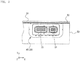
Figure 4 is a view showing attachment of the seal member to an electrical connector; -
Figure 5A is a bottom view of a connector assembly andFigure 5B is a side view of the connector assembly; -
Figure 6A is a view showing attachment of the connector assembly to a case andFigure 6B is an isometric view ofFigure 6A ; -
Figure 7 is a view showing the case having a lid attached thereto; -
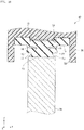
Figure 8 is a view showing an example of the state of the seal member in the connector assembly; -
Figure 9 is a view showing deformation of the seal member fromFigure 8 ; -
Figure 10 is a view showing deformation of the seal member fromFigure 9 ; -
Figures 11A to 11D are views schematically showing the deformation of the seal member; and -
Figure 12 is a graph showing a relation between the deformation and reaction force of the seal member. - Hereinbelow, with reference to the accompanying drawings, an embodiment of the present invention will be described. A
seal member 10 of the present embodiment is used to prevent water ingress between an electrical connector 30 (seeFigure 4 ) and acase 50 of an electronic equipment (seeFigures 6A and 6B ). It should be noted that a width direction X, a height direction Y and a thickness direction Z of each element of the present embodiment are defined as shown in the drawings. - The
seal member 10, as shown inFigure 4 ,Figures 5A and 5B , andFigures 6A and 6B , is attached over aside face portion 30a and abottom face portion 30b of theelectrical connector 30. Furthermore, as shown inFigure 6B , theseal member 10 is disposed between thecase 50 and theelectrical connector 30 when theelectrical connector 30 is attached to thecase 50 of the electronic equipment. - The
seal member 10 of the present embodiment is, for example, a rubber member integrally formed by injection molding. The overall shape of theseal member 10, as shown inFigures 1A and 1B , is a U-like shape opened on the upper side in the drawings. - The
seal member 10, as shown inFigure 2 , has amain body portion 11, a pair offirst flange portions 12, a pair ofsecond flange portions 13, a pair of projectingrim portions 14, and a pair oflip portions 15. - The
first flange portions 12 are so formed on an outer peripheral side of the main body portion 11 (the lower side ofFigure 2 ) as to protrude from both side faces, respectively, of themain body portion 11. Thesecond flange portions 13 are so formed on an inner peripheral side of the main body portion 11 (the upper side ofFigure 2 ) as to protrude from both side faces, respectively, of themain body portion 11. Thefirst flange portion 12 and thesecond flange portion 13 are provided with agroove 17 therebetween, and are thereby set smaller in dimension in the height direction Y than themain body portion 11. That is, thefirst flange portion 12 and thesecond flange portion 13 are connected like a cantilever to themain body portion 11. Therefore, thefirst flange portion 12 and thesecond flange portion 13 are one example of an easily-deformable portion that deforms easily under a load in the height direction Y. - The
main body portion 11 connects thefirst flange portion 12 on the outer peripheral side and thesecond flange portion 13 on the inner peripheral side vertically in the drawing. In theseal member 10, a portion composed of themain body portion 11, thefirst flange portion 12 and thesecond flange portion 13 has a substantially H-like shape rotated by 90 degrees in cross-section. Themain body portion 11 is larger in dimension in the height direction Y than thefirst flange portion 12 and thesecond flange portion 13. Therefore, in themain body portion 11, for example, the deformation amount in compression direction is minute under substantially the same load in the height direction Y as thefirst flange portion 12 and thesecond flange portion 13. - The projecting
rim portions 14 are connected to both sides, respectively, of thesecond flange portions 13. In the projectingrim portion 14, as shown inFigure 1B , receivingholes 14a and slits 14b are formed. The receivinghole 14a and theslit 14b, as shown inFigure 5A , engage with apin 35 and aprojection 36, respectively, provided on theelectrical connector 30, and function to align theseal member 10 with theelectrical connector 30. - As shown in
Figure 1B , in a pair ofarm portions 10a curved and extending in the height direction Y from both ends of abottom portion 10b of theseal member 10, supportingwalls 14c are formed from the respective projectingrim portions 14 in a direction toward the inner periphery. An engagingrecess 16 having a C-like shape in cross-section is formed in an inner peripheral face of theseal member 10. This engagingrecess 16 faces the supportingwalls 14c and themain body portion 11 in thearm portion 10a of theseal member 10, and faces the projectingrim portions 14 and themain body portion 11 in thebottom portion 10b of theseal member 10. An engaging protrusion 34 (seeFigure 8 ), described later, provided on an outer periphery of theelectrical connector 30 is engaged in the engagingrecess 16. - In addition, a guiding
groove 14d extending along the height direction Y is formed in an outer face of the supportingwall 14c, as shown inFigures 1A and 1B andFigure 4 . The guidinggroove 14d engages with a key, not shown, provided on theelectrical connector 30. The guidinggroove 14d guides theseal member 10 in the height direction Y that is an insertion/extraction direction when theseal member 10 is attached to theelectrical connector 30, and also functions as a retainer so that theseal member 10 will not become detached in the width direction X from theelectrical connector 30. - The
first flange portion 12 and thesecond flange portion 13 extend substantially parallel along the thickness direction Z, and protrude in the thickness direction Z more than themain body portion 11 from both the side faces of themain body portion 11. Therefore, thegroove 17 facing thefirst flange portion 12, thesecond flange portion 13 and themain body portion 11 and recessed in the thickness direction Z is formed in both side faces of theseal member 10. An example of thegroove 17 that is formed in a substantially V-like shape in cross-section is shown inFigure 2 . However, the cross-section of thegroove 17 may have another shape, for example, a C-like shape, a U-like shape, a semicircular shape, or the like. - When the
bottom portion 10b of theseal member 10 is compressed in the height direction Y, theseal member 10 deforms such that thefirst flange portion 12 and thesecond flange portion 13 deflect toward the inside of thegroove 17 to narrow the space of thegroove 17 in the height direction Y. At this time, with the compression of themain body portion 11, a reaction force occurs in the height direction Y. - In the
arm portion 10a of theseal member 10, the compression direction is from the inner peripheral side of theseal member 10 toward the outer peripheral side thereof, and theseal member 10 is compressed to deform in the same manner as thebottom portion 10b. Therefore, in thearm portion 10a, the compression direction is not coincident with the height direction Y. Hereinbelow, regarding the compression of theseal member 10, the case of thebottom portion 10b will be described unless otherwise noted. - As shown in
Figure 1A , thegroove 17 is formed along an extension direction of theseal member 10 from one end to another end of theseal member 10. In addition, a plurality ofribs 18 connected to thefirst flange portion 12 and thesecond flange portion 13 are positioned within thegroove 17. Theribs 18 are positioned at a predetermined interval in the extension direction of theseal member 10. Thisrib 18 functions to adjust the reaction force in the height direction Y when theseal member 10 is compressed in the height direction Y. Therib 18 is an example of a reinforcing portion. - Each
rib 18, as shown inFigure 3 , has afirst element 18a and asecond element 18b. One end of thefirst element 18a is connected to thefirst flange portion 12, and another end of thefirst element 18a is connected to one end of thesecond element 18b. In addition, another end of thesecond element 18b is connected to thesecond flange portion 13. Thefirst element 18a is so positioned as to be inclined with respect to the height direction Y of theseal member 10, and thesecond element 18b is so positioned as to be inclined in a direction opposite to thefirst element 18a with respect to the height direction Y of theseal member 10. Thefirst element 18a and thesecond element 18b are so connected together as to fold back in the middle in the height direction Y of theseal member 10. A portion connecting the other end of thefirst element 18a and the one end of thesecond element 18b is also referred to asbent portion 18c. Therefore, therib 18 is formed in a shape like a bent line in which thefirst element 18a and thesecond element 18b are bent and connected together. It should be noted that the shape of therib 18 is not limited to the shape like a bent line, but may have a curved shape, for example, an arc shape, or the like. - The
rib 18 supports thefirst flange portion 12 and thesecond flange portion 13 with elasticity due to bending. When thefirst flange portion 12 and thesecond flange portion 13 deflect toward the inside of thegroove 17, thefirst element 18a and thesecond element 18b deflect, thereby causing therib 18 to exert the reaction force in the height direction Y. Since thefirst element 18a and thesecond element 18b are each inclined with respect to the height direction Y, when therib 18 receives a load in the height direction Y, thefirst element 18a and thesecond element 18b fall down easily. Therefore, when theseal member 10 is compressed in the height direction Y, with the deformation of thefirst flange portion 12 and thesecond flange portion 13 deflecting toward the inside of thegroove 17, therib 18 deforms such that an angle formed between thefirst element 18a and thesecond element 18b decreases gradually. Since being bent, therib 18 is more easily deformable than thefirst flange portion 12 and thesecond flange portion 13, thus not obstructing the deformation of thefirst flange portion 12 and thesecond flange portion 13. - The
respective ribs 18, as shown inFigure 1A , have bending directions of theribs 18 in thearm portion 10a oriented uniformly in a clockwise direction from the end on the right side in the drawing of theseal member 10 toward thebottom portion 10b. In addition, from the end on the left side in the drawing of theseal member 10 toward thebottom portion 10b, bending directions of theribs 18 in thearm portion 10a are oriented uniformly in a counterclockwise direction. - That is, in the
seal member 10, the arrangement of theribs 18 on the left side ofFigure 1A and the arrangement of theribs 18 on the right side ofFigure 1A are bilaterally symmetrical. Since theribs 18 of theseal member 10 are in a bilaterally-symmetrical arrangement, the deformations of thefirst flange portion 12 and thesecond flange portion 13 in the right and leftarm portions 10a are easily equalized. - In addition, when the
seal member 10 is pressed into the case, thebottom portion 10b of theseal member 10 receives a compressive load from the height direction Y. On the other hand, since extending along the height direction Y, thearm portion 10a of theseal member 10 receives a load in the extension direction of the seal member when theseal member 10 is pressed in. In the present embodiment, as described above, the bending directions of theribs 18 in thearm portion 10a are oriented uniformly from the end of the seal member toward thebottom portion 10b. Therefore, in thearm portion 10a, theribs 18 easily bend in a pressing direction of theseal member 10. - It should be noted that, though the arrangement of the
groove 17 and theribs 18 on one side face of the seal member 10 (a front face side of the electrical connector 30) is shown inFigure 1A , the arrangement of thegroove 17 and theribs 18 on another side face of the seal member 10 (a back face side of the electrical connector 30) is also similar to that on the one side face. - The pair of
lip portions 15, as shown inFigure 2 , are provided upright on an outer peripheral side (the lower side ofFigure 2 ) of thefirst flange portions 12, respectively, of themain body portion 11. As shown inFigure 1A , the pair oflip portions 15 are formed along the extension direction of theseal member 10 from the one end to the other end of theseal member 10. In addition, in the present embodiment, the cross-section of eachlip portion 15 has an isosceles-triangular shape, the base of which is connected to thefirst flange portion 12. It should be noted that the cross-section of thelip portion 15 is not limited to the isosceles-triangular shape, but may have another shape, for example, a scalene-triangular shape, or the like. - The
lip portion 15 is supported by thefirst flange portion 12, and avertex 15a of thelip portion 15, as shown inFigure 2 , is located in a region where thegroove 17 is formed in the thickness direction Z. That is, thevertex 15a of thelip portion 15 is located more externally than themain body portion 11 in the thickness direction Z. Therefore, in the thickness direction Z, an interval L1 between thevertices 15a of the pair oflip portions 15 is set larger than a width L2 of the main body portion 11 (L1 > L2). - When the
seal member 10 is compressed in the height direction Y, thefirst flange portion 12 deflects toward the inside of thegroove 17. In addition, thelip portion 15 supported by thefirst flange portion 12 deforms so as to fall toward the outside of theseal member 10. Therefore, when theseal member 10 is compressed in the height direction Y, the pair oflip portions 15 deform so as to widen the interval between their distal ends. - The
electrical connector 30 of the present embodiment is a male connector configured to be mated with a mating connector, not shown, in the thickness direction Z that is a connector mating direction. As shown inFigures 6A and 6B , theelectrical connector 30 is attached to an edge portion of awiring board 52 mounted on the electronic equipment. - A
housing 31 of theelectrical connector 30 is integrally formed by injection molding of, for example, an electrically-insulating resin material (polybutylene terephthalate, or the like). In thehousing 31, as shown inFigure 5B , aseal retaining portion 32 for retaining theseal member 10 is formed over aside face portion 30a and abottom face portion 30b of theelectrical connector 30. In addition, a threadedhole 31a used for fixation to thewiring board 52 is provided in a back face of thehousing 31. - The
housing 31 of theelectrical connector 30 retains each of a plurality ofmale contacts 33 extending in the thickness direction Z. Themale contact 33 is formed by stamping an electrically-conductive metal material, for example, a copper alloy sheet material. Eachmale contact 33 is led out from a front face side to a back face side of thehousing 31, and electrically connected to a through-hole, not shown, of thewiring board 52 on the back face side. - Within the
seal retaining portion 32, the engaging protrusion 34 (seeFigures 8 to 10 ) is formed along the extension direction of theseal retaining portion 32. In addition, thepins 35 for engaging with the receivingholes 14a and theprojections 36 for engaging with theslits 14b are each formed within theseal retaining portion 32. - The
seal member 10 can be attached to theseal retaining portion 32 of theelectrical connector 30, as shown inFigure 4 , from the lower side in the drawing. In the present embodiment, theelectrical connector 30 having theseal member 10 attached thereto is also referred to asconnector assembly 40. - The
case 50 of the present embodiment, as shown inFigures 6A and 6B , is an enclosure opened on the upper face side in the drawings, and thewiring board 52 can be accommodated in thecase 50. An upper face of thecase 50 is closed with alid 51. Though thecase 50 and thelid 51 of the present embodiment are formed from a metal material, for example, an aluminum alloy, or the like, thecase 50 and thelid 51 may be formed by injection molding of a resin material. - A
notch 50a corresponding to the contour of theelectrical connector 30 is formed in thecase 50. Thisnotch 50a has an inverted trapezoidal shape wider on an open-top side and narrower on a bottom side. When thewiring board 52 is accommodated into thecase 50, theconnector assembly 40 can be engaged with thenotch 50a from the upper side ofFigure 6 to expose the front face side of theelectrical connector 30 outside thecase 50. At this time, between theconnector assembly 40 and thenotch 50a of thecase 50, waterproofness is ensured by theseal member 10 attached to theelectrical connector 30. - In addition, with the
connector assembly 40 attached to thecase 50, anupper face portion 30c of theelectrical connector 30 engaged with thenotch 50a and anupper face 50b of thecase 50 are flush with each other. Though theseal member 10 is not positioned on theupper face portion 30c of theelectrical connector 30, awaterproof layer 53 is formed by applying liquid gasket between theupper face portion 30c of theelectrical connector 30, theupper face 50b of thecase 50 and thelid 51, as shown inFigure 7 . Thiswaterproof layer 53 ensures waterproofness between theupper face portion 30c of theelectrical connector 30 and thelid 51 and between theupper face 50b of thecase 50 and thelid 51. - In assembly of the electronic equipment, the
wiring board 52 is positioned within thecase 50. At this time, theconnector assembly 40 attached to thewiring board 52 is inserted into thenotch 50a of thecase 50. The shape of thenotch 50a is an inverted trapezoidal shape wider on the open-top side and narrower on the bottom side. Therefore, without interference of theseal member 10 of theconnector assembly 40 with the open top of thenotch 50a, theelectrical connector 30 can be inserted into thenotch 50a. Thereby, theconnector assembly 40 can be easily positioned in thenotch 50a. - When the
connector assembly 40 is positioned in thenotch 50a of thecase 50, thelip portion 15 of theseal member 10 comes into contact with thecase 50. In this state, excluding the self-weight of theconnector assembly 40, a force is not applied to theseal member 10 from the upper side in the drawing. Therefore, in thebottom face portion 30b of theelectrical connector 30, the pair oflip portions 15 keep their shapes upright along the height direction Y (seeFigure 8 ). - Next, the liquid gasket is applied to the
upper face portion 30c of theelectrical connector 30 and theupper face 50b of thecase 50. Thereafter, thelid 51 is attached to thecase 50. When thelid 51 is attached to thecase 50, theconnector assembly 40 is pressed by thelid 51 into thenotch 50a. Thereby, in thebottom face portion 30b and theside face portion 30a of theelectrical connector 30, theseal member 10 deforms in the following manner. - The course of deformation of the
seal member 10 in thebottom face portion 30b of theelectrical connector 30 is schematically shown inFigures 11A to 11D . InFigures 11A to 11D , the elements of theseal member 10 are modeled and thereby simply shown. -
Figure 11A shows an initial state in which theseal member 10 has not been compressed. The state shown inFigure 11A corresponds toFigure 8 . - Since being thinner in dimension in the thickness direction Z than the
main body portion 11, eachlip portion 15 deflects more easily than themain body portion 11. In addition, thelip portion 15 is supported by thefirst flange portion 12 having a smaller dimension in the thickness direction Z than themain body portion 11 due to the formation of thegroove 17. As described above, thefirst flange portion 12 deflects to deform more easily than the thickermain body portion 11. Moreover, thevertex 15a of thelip portion 15 is located more externally than themain body portion 11 in the thickness direction Z. - Therefore, when the
seal member 10 is compressed in the height direction Y, thelip portions 15 in contact with thecase 50 deform elastically so as to separate their distal ends contacting thecase 50 from each other, that is, to spread outward, and start to incline, as shown inFigure 9 andFigure 11B . Thefirst flange portion 12 receives a load in conjunction with inclination of thelip portion 15, and therefore deflects slightly toward the inside of thegroove 17. At this time, themain body portion 11 undergoes little, if any, compressive deformation. - Then, as the
seal member 10 further receives the load in the height direction Y, the deformation progresses such that thelip portion 15 inclines further to fall down, as shown inFigure 11C . In this manner, as the displacement of theelectrical connector 30 toward thecase 50 increases, the interval between the distal ends of thelip portions 15 becomes wider. - In addition, as the displacement of the
case 50 further increases, the deflection of thefirst flange portion 12 and thesecond flange portion 13 reaches the limit, and the deformation of thelip portions 15 also reaches the limit, as shown inFigure 11D . Thereupon, compressive deformation occurs in themain body portion 11, and a reaction force of theseal member 10 due to themain body portion 11 occurs. -
Figure 10 shows a state in which thefirst flange portion 12 and thesecond flange portion 13 are in contact with each other and the deflection of thefirst flange portion 12 and thesecond flange portion 13 has reached the limit. In the state shown inFigure 10 , the dimension in the height direction Y of themain body portion 11 is larger than the combined dimension in the height direction Y of thefirst flange portion 12 and thesecond flange portion 13. Therefore, when theelectrical connector 30 is so displaced as to approach thecase 50, themain body portion 11 receives a load due to this displacement to undergo compressive deformation. This causes both the pair oflip portions 15 of theseal member 10 to spread outward and contact thecase 50, and causes thesecond flange portion 13 of theseal member 10 to come into contact with the engagingprotrusion 34 of theconnector assembly 40. At this time, the compressive deformation of themain body portion 11 in the height direction Y causes thelip portion 15 to come into close contact with thecase 50, and causes thesecond flange portion 13 to come into close contact with the engagingprotrusion 34. Thereby, waterproofness between thecase 50 and theelectrical connector 30 is ensured. - Next, the deformation of the
seal member 10 in theside face portion 30a of theelectrical connector 30 will be described. When theseal member 10 is pressed from the upper side in the drawings, theseal member 10 moves toward the lower side in the drawings, and thereby a space between theseal member 10 and thenotch 50a becomes small in theside face portion 30a of theelectrical connector 30. Thereby, theseal member 10 is also pressed to thenotch 50a in theside face portion 30a of theelectrical connector 30, and thus theseal member 10 deforms in the same manner as thebottom face portion 30b. - In this regard, when the
seal member 10 is pressed into the case, thebottom portion 10b of theseal member 10 receives the compressive load from the height direction Y. On the other hand, since extending along the height direction Y, thearm portion 10a of theseal member 10 receives a load from the extension direction of theseal member 10 when theseal member 10 is pressed in. Theribs 18 of theseal member 10 in the present embodiment have the bending directions of theribs 18 in thearm portion 10a oriented uniformly from the end of theseal member 10 toward thebottom portion 10b. That is, in theside face portion 30a of theelectrical connector 30, eachrib 18 easily bends in the downward direction in the drawings that is a direction in which theseal member 10 is pressed in. Therefore, in theside face portion 30a of theelectrical connector 30, the direction in which theribs 18 easily bend and the direction in which theseal member 10 is pressed in are coincident with each other, so that theribs 18 of thearm portion 10a easily bend when theseal member 10 is pressed in. - Hereinbelow, with reference to
Figure 12 , a relation between the deformation and reaction force of theseal member 10 of the present embodiment will be described. In this regard, the vertical axis ofFigure 12 indicates the load (reaction force) when theseal member 10 is compressed in the height direction Y, and the horizontal axis ofFigure 12 indicates the amount of displacement in the height direction Y of theseal member 10 after thecase 50 comes into contact with thelip portions 15. - The
seal member 10, as shown inFigure 12 , develops an initial elastic region S1 where the reaction force increases proportionally with respect to the amount of displacement, an intermediate region S2, following the initial elastic region S1, where the reaction force hardly increases with respect to the amount of displacement, and a late elastic region S3, following the intermediate region S2, where the reaction force increases proportionally with respect to the amount of displacement. - In the initial elastic region S1, with the displacement of the
case 50 after thecase 50 comes into contact with the distal ends of thelip portions 15 in theseal member 10, thelip portions 15, thefirst flange portions 12 and thesecond flange portions 13 undergo the deformation described above. The initial elastic region S1 corresponds to, for example,Figures 11A and 11B . - The intermediate region S2 is a range within which the deformation of the
lip portions 15, thefirst flange portions 12 and thesecond flange portions 13 further progresses, for example, until the amount of deformation reaches the limit after thefirst flange portions 12 and thesecond flange portions 13 come into contact with each other. In this period, regardless of an increase in the amount of displacement of thecase 50, the reaction force of theseal member 10 hardly increases, since thelip portions 15, thefirst flange portions 12 and thesecond flange portions 13 deform very easily. - In the late elastic region S3, after the deformation of the
first flange portions 12 and thesecond flange portions 13 reaches the limit, further displacement of thecase 50 causes a reaction force in themain body portion 11. This reaction force of themain body portion 11 increases in proportion to the amount of displacement in the height direction Y of thecase 50. - In this regard, the magnitude of the reaction force in each region is determined by the material of the
seal member 10 and/or the shape and dimensions of therib 18. In particular, in the region S2, the compression of themain body portion 11 and therib 18 causes the reaction force. For example, in order to increase the reaction force in the region S2, the number ofribs 18 may be increased or eachrib 18 may be thickened. In order to decrease the reaction force in the region S2, the number ofribs 18 may be reduced or eachrib 18 may be thinned. In this manner, in the present embodiment, by adjusting the shape and dimensions of therib 18 of theseal member 10, the reaction force of theseal member 10 can be easily adjusted without changing the material of theseal member 10. - Hereinafter, advantageous effects of the
seal member 10 of the present embodiment will be described. In theseal member 10 of the present embodiment, thelip portions 15, thefirst flange portion 12 and thesecond flange portion 13 deform ahead of themain body portion 11 after thelip portions 15 come into contact with thecase 50 and until the deformation of thefirst flange portion 12 and thesecond flange portion 13 reaches the limit. Since thelip portions 15, thefirst flange portion 12 and thesecond flange portion 13 of theseal member 10 are easily deformable, the reaction force that occurs in theseal member 10 is small. Therefore, a force required for the work of attaching theconnector assembly 40 to thecase 50 can be reduced. - After the deformation of the
first flange portion 12 and thesecond flange portion 13 reaches the limit, themain body portion 11 undergoes elastic deformation in place of thelip portions 15, thefirst flange portion 12 and thesecond flange portion 13, and exerts the reaction force. Since being not easily elastically deformable, themain body portion 11 exerts a larger reaction force than thelip portions 15, or the like, does. Thereby, the waterproof performance of theseal member 10 can be ensured. - In addition, the
ribs 18 receiving the compressive load are formed between thefirst flange portion 12 and thesecond flange portion 13. Since thefirst flange portion 12 and thesecond flange portion 13 are supported by theribs 18 and thereby exert the reaction force, the reaction force of theseal member 10 can be compensated by theribs 18. Since being bent, theribs 18 are more easily deformable than thefirst flange portion 12 and thesecond flange portion 13, and therefore do not obstruct the deformation of thefirst flange portion 12 and thesecond flange portion 13. In addition, fine adjustment of the magnitude of the reaction force that occurs in theseal member 10 can also be made by means of the shape and dimensions of therib 18. - In the
seal member 10 of the present embodiment, the pair oflip portions 15 are supported by thefirst flange portions 12, respectively, each protruding from both sides on the outer peripheral side of themain body portion 11. Furthermore, thevertices 15a of the pair oflip portions 15 in cross-section are located more externally than themain body portion 11. Therefore, in the present embodiment, in the thickness direction Z, the interval L1 between thevertices 15a of thelip portions 15 is set larger than the width L2 of the main body portion 11 (L1 > L2). This causes thelip portion 15 to deform so as to fall outward with the deflection of thefirst flange portion 12 when a force is applied to thelip portions 15, so that the pair oflip portions 15 can be so deformed as to widen the interval between their distal ends. - In addition, the
seal member 10 of the present embodiment has a U-like overall shape, and is attached to thebottom face portion 30b and theside face portion 30a of theelectrical connector 30. In assembly of the electronic equipment, the elastic deformation of theseal member 10 can absorb a dimensional tolerance in the width direction X or the height direction Y of theconnector assembly 40 and thenotch 50a. - In addition, the
seal member 10 of the present embodiment is attached to thebottom face portion 30b and theside face portion 30a of theelectrical connector 30. That is, in assembly of the electronic equipment, theseal member 10, which exerts a reaction force, is not provided on theupper face portion 30c of theelectrical connector 30 that is a face to be contacted with thelid 51. Therefore, a condition when thelid 51 is attached to theupper face portion 30c of theelectrical connector 30 and a condition when thelid 51 is attached to theupper face 50b of thecase 50 can be made uniform, so that the working efficiency in assembling the electronic equipment can be improved. - In addition to the above, the configurations mentioned in the above embodiment may be selectively adopted and/or eliminated or, if appropriate, may be modified to another configuration unless such selective adoption and/or elimination departs from the scope of the claimed invention.
- For example, in the above embodiment, the illustrative configuration has been described in which the
seal member 10 is attached to theelectrical connector 30, but theseal member 10 may be attached to thecase 50. In addition, thelip portion 15 of theseal member 10 may be provided on a face to be attached to theelectrical connector 30. In addition, in the above embodiment, theribs 18 may not be provided in thegroove 17 of theseal member 10. - In addition, in the above embodiment, the distal end of the
lip portion 15 may be so formed preliminarily as to be inclined outward. In this case, without the vertex of thelip portion 15 located more externally than themain body portion 11, thelip portion 15 can be so deformed as to incline outward. - In the above embodiment, the example has been described in which the easily-deformable portions are provided by providing the
groove 17 in both sides (both ends) in the thickness direction Z of themain body portion 11. However, the easily-deformable portion of the present invention is not limited to the above embodiment as long as it is composed of a portion thinner than the main body portion. For example, agroove 17 may be provided in the center in the thickness direction Z of themain body portion 11 so that the pair oflip portions 15 can be inclined inward. In this case, the main body portion corresponds to amain body portion 11 which is solid on both sides (both ends) in the thickness direction Z. -
- 10
- seal member
- 10a
- arm portion
- 10b
- bottom portion
- 11
- main body portion
- 12
- first flange portion (easily-deformable portion)
- 13
- second flange portion (easily-deformable portion)
- 14
- projecting rim portion
- 14a
- receiving hole
- 14b
- slit
- 14c
- supporting wall
- 14d
- guide groove
- 15
- lip portion
- 15a
- vertex
- 16
- engaging recess
- 17
- groove
- 18
- rib (reinforcing portion)
- 18a
- first element
- 18b
- second element
- 18c
- bent portion
- 30
- electrical connector
- 30a
- side face portion
- 30b
- bottom face portion
- 30c
- upper face portion
- 31
- housing
- 31a
- threaded hole
- 32
- seal retaining portion
- 33
- male contact
- 34
- engaging protrusion
- 35
- pin
- 36
- projection
- 40
- connector assembly
- 50
- case
- 50a
- notch
- 50b
- upper face
- 51
- lid
- 52
- wiring board
- 53
- waterproof layer
Claims (16)
- A seal member (10) that elastically deforms under a compressive load, comprising:a main body portion (11);a deformable part body portion (12) formed integrally with the main body portion (11), and being is more easily deformable than the main body portion; anda pair of lip portions (15) formed on one face side of the seal member (10) in a loading direction in which the compressive load acts, whereinthe compressive load acting on the pair of lip portions (15) acts on the deformable part body portion (12).
- The seal member according to claim 1, wherein the deformable part body portion has a first flange portion (12) protruding from a side face of the main body portion (11) on one face side of the main body portion, and
the first flange portion (12) is so formed as to be thinner in dimension in the loading direction than the main body portion (11). - The seal member according to claim 2, wherein the deformable part body portion further has a second flange portion (13) protruding from a side face of the main body portion (11) on another face side of the main body portion.
- The seal member according to claim 3, further comprising a rib (18) connected to the first flange portion (12) and the second flange portion (13).
- The seal member according to any preceding claim, wherein vertices (15a) of the pair of lip portions (15) in cross-section are located more externally than the main body portion (11).
- The seal member according to any preceding claim, wherein an interval (L1) between the vertices (15a) of the pair of lip portions (15) in cross-section is set larger than a width (L2) of the main body portion (11).
- The seal member according claim 1, including
a plurality of reinforcing portions (18) being more easily deformable than the deformable part body portion (12) and supporting the deformable part body portion. - The seal member according to claim 7, wherein the plurality of reinforcing portions (18) are formed at an interval in an extension direction of the seal member (10).
- The seal member according to claim 7 or 8, wherein
the deformable part body portion has
a first flange portion (12) protruding from a side face of the main body portion (11) on one face side of the main body portion, and
a second flange portion (13) protruding from a side face of the main body portion (11) on another face side of the main body portion, and
the reinforcing portions are ribs (18) connected to the first flange portion (12) and the second flange portion (13). - The seal member according to claim 9, wherein
the first flange portion (12) and the second flange portion (13) are so formed as to be thinner in dimension in the loading direction in which the compressive load acts than the main body portion (11). - The seal member according to any one of claims 7 to 10, wherein
the reinforcing portions (18) support the deformable part body portion (12) with elasticity based on bending. - The seal member according to claim 11, wherein the reinforcing portions (18) have a bent shape.
- The seal member according to claim 12, wherein
the seal member (10) has a U-like shape having a bottom portion (10b) and two arm portions (10a) each connected to the bottom portion, and
the reinforcing portions (18) have bending directions of the reinforcing portions oriented uniformly from an end of the arm portion (10a) toward the bottom portion (10b). - The seal member according to any one of claims 1 to 12, having a U-like overall shape.
- The seal member according to any preceding claim, wherein the deformable part body portion is an easily-deformable portion (12) formed integrally with the main body portion (11).
- A connector assembly (40) comprising:an electrical connector (30); andthe seal member (10) according to any preceding claim, being attached to the electrical connector (30).
Applications Claiming Priority (2)
| Application Number | Priority Date | Filing Date | Title |
|---|---|---|---|
| JP2018181277A JP7158225B2 (en) | 2018-09-27 | 2018-09-27 | Sealing member and connector assembly |
| JP2018181276A JP7182414B2 (en) | 2018-09-27 | 2018-09-27 | Sealing member and connector assembly |
Publications (1)
| Publication Number | Publication Date |
|---|---|
| EP3629426A1 true EP3629426A1 (en) | 2020-04-01 |
Family
ID=68066606
Family Applications (1)
| Application Number | Title | Priority Date | Filing Date |
|---|---|---|---|
| EP19199199.1A Withdrawn EP3629426A1 (en) | 2018-09-27 | 2019-09-24 | Seal member and connector assembly |
Country Status (3)
| Country | Link |
|---|---|
| US (1) | US20200106209A1 (en) |
| EP (1) | EP3629426A1 (en) |
| CN (1) | CN110957609B (en) |
Cited By (1)
| Publication number | Priority date | Publication date | Assignee | Title |
|---|---|---|---|---|
| EP4350179A1 (en) * | 2022-10-04 | 2024-04-10 | Tyco Electronics Japan G.K. | Sealing element and connector assembly |
Families Citing this family (1)
| Publication number | Priority date | Publication date | Assignee | Title |
|---|---|---|---|---|
| JP7633135B2 (en) * | 2021-10-19 | 2025-02-19 | 矢崎総業株式会社 | connector |
Citations (5)
| Publication number | Priority date | Publication date | Assignee | Title |
|---|---|---|---|---|
| JPH08315904A (en) * | 1995-05-17 | 1996-11-29 | Sumitomo Wiring Syst Ltd | Rubber seal |
| WO1997043803A1 (en) * | 1996-05-17 | 1997-11-20 | The Whitaker Corporation | Sealing member for waterproof connector |
| US6244886B1 (en) * | 2000-01-24 | 2001-06-12 | Delphi Technologies, Inc. | Electrical connection system having force distribution seal |
| JP2005229711A (en) | 2004-02-12 | 2005-08-25 | Yazaki Corp | Grommet |
| JP2007239958A (en) * | 2006-03-10 | 2007-09-20 | Nok Corp | Gasket |
Family Cites Families (30)
| Publication number | Priority date | Publication date | Assignee | Title |
|---|---|---|---|---|
| DE3716252A1 (en) * | 1987-05-15 | 1988-12-01 | Ksa Dichtsysteme | DEVICE FOR SEALING CONNECTED CABLES OF CABLES |
| FR2644217A1 (en) * | 1989-03-07 | 1990-09-14 | Procal | STATIC SEAL SEAL |
| US5469963A (en) * | 1992-04-08 | 1995-11-28 | Asyst Technologies, Inc. | Sealable transportable container having improved liner |
| US5551705A (en) * | 1995-07-12 | 1996-09-03 | Fel-Pro Incorporated | Double beaded spaghetti seal with stiffness increasing deformation behavior |
| DE10017221A1 (en) * | 2000-04-06 | 2001-10-11 | Ralph Peter Hegler | Sealing ring for connection between the spigot end of a corrugated pipe and pipe socket with a smooth inner wall |
| US7413099B2 (en) * | 2001-06-08 | 2008-08-19 | Shin-Etsu Polymer Co., Ltd. | Sealing element with a protruding part approximately obliquely outward and a hermetic container using the same |
| US6719302B2 (en) * | 2001-07-02 | 2004-04-13 | Vertex, Inc. | Symmetrical gasket for a pipe joint with increased surface contact |
| KR20070057846A (en) * | 2004-08-20 | 2007-06-07 | 페데럴 모걸 실링 시스템즈 브리텐 게엠베하 | Cylinder head cover for cylinder head of internal combustion engine |
| JP2008536277A (en) * | 2005-04-11 | 2008-09-04 | エフシーアイ | Grommet for electrical connector and electrical connector equipped with such grommet |
| JP4482655B2 (en) * | 2005-04-22 | 2010-06-16 | ゴールド工業株式会社 | Gasket for precision substrate storage container |
| WO2007007612A1 (en) * | 2005-07-07 | 2007-01-18 | Nok Corporation | Gasket |
| JP2007107546A (en) * | 2005-09-16 | 2007-04-26 | Nok Corp | Gasket |
| US7314590B2 (en) * | 2005-09-20 | 2008-01-01 | Bayer Materialscience Llc | Method of preparing a coated molded plastic article |
| US7371115B1 (en) * | 2006-12-15 | 2008-05-13 | Delphi Technologies, Inc. | Mat seal device |
| JP4739264B2 (en) * | 2007-03-30 | 2011-08-03 | Nok株式会社 | Sealing structure and gasket |
| JP5151241B2 (en) * | 2007-05-10 | 2013-02-27 | Nok株式会社 | Sealing structure |
| JP4755268B2 (en) * | 2009-03-05 | 2011-08-24 | 日本航空電子工業株式会社 | Cap and connector device |
| US8167660B2 (en) * | 2009-09-04 | 2012-05-01 | Bal Seal Engineering, Inc. | Connector assemblies for use with implantable medical devices |
| DE102010029982A1 (en) * | 2010-06-11 | 2011-12-15 | Robert Bosch Gmbh | Fluid sealed electric motor connector, as well as motor and pre-assembled electrical cable |
| JP5629512B2 (en) * | 2010-07-20 | 2014-11-19 | 矢崎総業株式会社 | Connector with cover |
| JP5569297B2 (en) * | 2010-09-24 | 2014-08-13 | 住友電装株式会社 | Waterproof connector |
| DE102010064071B3 (en) * | 2010-12-23 | 2012-05-24 | Tyco Electronics Amp Gmbh | Clamping ring, cable gland and method for mounting a cable gland |
| JP5644563B2 (en) * | 2011-02-07 | 2014-12-24 | 住友電装株式会社 | connector |
| JP2015521377A (en) * | 2012-05-04 | 2015-07-27 | インテグリス・インコーポレーテッド | Wafer container with door contact seal |
| EP3352310B1 (en) * | 2013-02-19 | 2020-04-08 | CommScope Connectivity Belgium BVBA | Sealing interface for a telecommunications enclosure |
| JP6360351B2 (en) * | 2014-05-20 | 2018-07-18 | 矢崎総業株式会社 | Waterproof stopper |
| US10106107B2 (en) * | 2014-11-13 | 2018-10-23 | Mitsubishi Electric Corporation | Waterproof type control unit and waterproof type control unit manufacturing method |
| JP6314909B2 (en) * | 2015-05-28 | 2018-04-25 | 住友電装株式会社 | Rubber stopper assembly |
| CN108879156B (en) * | 2017-05-12 | 2024-02-09 | 泰科电子(上海)有限公司 | Electrical protective covers and sockets |
| JP7019147B2 (en) * | 2018-05-09 | 2022-02-15 | 日本圧着端子製造株式会社 | Waterproof structure of waterproof connector and equipment case |
-
2019
- 2019-09-24 EP EP19199199.1A patent/EP3629426A1/en not_active Withdrawn
- 2019-09-25 CN CN201910909855.9A patent/CN110957609B/en active Active
- 2019-09-26 US US16/583,760 patent/US20200106209A1/en not_active Abandoned
Patent Citations (5)
| Publication number | Priority date | Publication date | Assignee | Title |
|---|---|---|---|---|
| JPH08315904A (en) * | 1995-05-17 | 1996-11-29 | Sumitomo Wiring Syst Ltd | Rubber seal |
| WO1997043803A1 (en) * | 1996-05-17 | 1997-11-20 | The Whitaker Corporation | Sealing member for waterproof connector |
| US6244886B1 (en) * | 2000-01-24 | 2001-06-12 | Delphi Technologies, Inc. | Electrical connection system having force distribution seal |
| JP2005229711A (en) | 2004-02-12 | 2005-08-25 | Yazaki Corp | Grommet |
| JP2007239958A (en) * | 2006-03-10 | 2007-09-20 | Nok Corp | Gasket |
Cited By (1)
| Publication number | Priority date | Publication date | Assignee | Title |
|---|---|---|---|---|
| EP4350179A1 (en) * | 2022-10-04 | 2024-04-10 | Tyco Electronics Japan G.K. | Sealing element and connector assembly |
Also Published As
| Publication number | Publication date |
|---|---|
| CN110957609B (en) | 2023-07-21 |
| US20200106209A1 (en) | 2020-04-02 |
| CN110957609A (en) | 2020-04-03 |
Similar Documents
| Publication | Publication Date | Title |
|---|---|---|
| JP4841756B2 (en) | Contact and electrical connector with this | |
| US7938695B2 (en) | Terminal fitting | |
| US7670150B2 (en) | Low profile board-mounted connector | |
| EP2701238B1 (en) | Electric connector | |
| US11196207B2 (en) | Card edge connector with protective cover | |
| KR20090012072A (en) | Electrical Connectors for Circuit Boards | |
| EP3343702A1 (en) | Terminal block | |
| US20240235117A9 (en) | First connector and connector assembly with unlocking slider | |
| EP3629426A1 (en) | Seal member and connector assembly | |
| WO2012153472A1 (en) | Connector terminal, and card edge type connector including this connector terminal | |
| EP1930983A2 (en) | Electrical connector | |
| US6239358B1 (en) | I/O shield for electronic assemblies | |
| EP1414113B1 (en) | Housing, connector, and connector connecting method | |
| CN103219604A (en) | Electric connector having shielding plate | |
| EP1244180A2 (en) | Electrical connector for flat cable and its manufacturing method | |
| JP2017157365A (en) | Contact connection structure | |
| JP5556535B2 (en) | Electronic equipment | |
| JP7158225B2 (en) | Sealing member and connector assembly | |
| JP7182414B2 (en) | Sealing member and connector assembly | |
| KR101613410B1 (en) | Terminal fitting | |
| CN117855930A (en) | Sealing components and connector assemblies | |
| CN1122333C (en) | Electrical connector | |
| KR100591116B1 (en) | Electric connector | |
| JP2005339837A (en) | Low profile card connector | |
| JP2023025615A (en) | Connector and electronic apparatus |
Legal Events
| Date | Code | Title | Description |
|---|---|---|---|
| PUAI | Public reference made under article 153(3) epc to a published international application that has entered the european phase |
Free format text: ORIGINAL CODE: 0009012 |
|
| STAA | Information on the status of an ep patent application or granted ep patent |
Free format text: STATUS: THE APPLICATION HAS BEEN PUBLISHED |
|
| AK | Designated contracting states |
Kind code of ref document: A1 Designated state(s): AL AT BE BG CH CY CZ DE DK EE ES FI FR GB GR HR HU IE IS IT LI LT LU LV MC MK MT NL NO PL PT RO RS SE SI SK SM TR |
|
| AX | Request for extension of the european patent |
Extension state: BA ME |
|
| 18D | Application deemed to be withdrawn |
Effective date: 20201002 |