EP3629391A1 - Fingered capacitor with low-k and ultra-low-k dielectric layers - Google Patents
Fingered capacitor with low-k and ultra-low-k dielectric layers Download PDFInfo
- Publication number
- EP3629391A1 EP3629391A1 EP19197724.8A EP19197724A EP3629391A1 EP 3629391 A1 EP3629391 A1 EP 3629391A1 EP 19197724 A EP19197724 A EP 19197724A EP 3629391 A1 EP3629391 A1 EP 3629391A1
- Authority
- EP
- European Patent Office
- Prior art keywords
- layer
- dielectric
- dielectric layer
- low
- fingers
- Prior art date
- Legal status (The legal status is an assumption and is not a legal conclusion. Google has not performed a legal analysis and makes no representation as to the accuracy of the status listed.)
- Withdrawn
Links
Images


Classifications
-
- H—ELECTRICITY
- H01—ELECTRIC ELEMENTS
- H01L—SEMICONDUCTOR DEVICES NOT COVERED BY CLASS H10
- H01L21/00—Processes or apparatus adapted for the manufacture or treatment of semiconductor or solid state devices or of parts thereof
- H01L21/70—Manufacture or treatment of devices consisting of a plurality of solid state components formed in or on a common substrate or of parts thereof; Manufacture of integrated circuit devices or of parts thereof
- H01L21/71—Manufacture of specific parts of devices defined in group H01L21/70
- H01L21/768—Applying interconnections to be used for carrying current between separate components within a device comprising conductors and dielectrics
- H01L21/76801—Applying interconnections to be used for carrying current between separate components within a device comprising conductors and dielectrics characterised by the formation and the after-treatment of the dielectrics, e.g. smoothing
- H01L21/76829—Applying interconnections to be used for carrying current between separate components within a device comprising conductors and dielectrics characterised by the formation and the after-treatment of the dielectrics, e.g. smoothing characterised by the formation of thin functional dielectric layers, e.g. dielectric etch-stop, barrier, capping or liner layers
- H01L21/76832—Multiple layers
-
- H—ELECTRICITY
- H01—ELECTRIC ELEMENTS
- H01L—SEMICONDUCTOR DEVICES NOT COVERED BY CLASS H10
- H01L28/00—Passive two-terminal components without a potential-jump or surface barrier for integrated circuits; Details thereof; Multistep manufacturing processes therefor
- H01L28/40—Capacitors
-
- H—ELECTRICITY
- H01—ELECTRIC ELEMENTS
- H01L—SEMICONDUCTOR DEVICES NOT COVERED BY CLASS H10
- H01L28/00—Passive two-terminal components without a potential-jump or surface barrier for integrated circuits; Details thereof; Multistep manufacturing processes therefor
- H01L28/40—Capacitors
- H01L28/60—Electrodes
-
- H—ELECTRICITY
- H01—ELECTRIC ELEMENTS
- H01L—SEMICONDUCTOR DEVICES NOT COVERED BY CLASS H10
- H01L21/00—Processes or apparatus adapted for the manufacture or treatment of semiconductor or solid state devices or of parts thereof
- H01L21/02—Manufacture or treatment of semiconductor devices or of parts thereof
- H01L21/04—Manufacture or treatment of semiconductor devices or of parts thereof the devices having at least one potential-jump barrier or surface barrier, e.g. PN junction, depletion layer or carrier concentration layer
- H01L21/18—Manufacture or treatment of semiconductor devices or of parts thereof the devices having at least one potential-jump barrier or surface barrier, e.g. PN junction, depletion layer or carrier concentration layer the devices having semiconductor bodies comprising elements of Group IV of the Periodic System or AIIIBV compounds with or without impurities, e.g. doping materials
- H01L21/30—Treatment of semiconductor bodies using processes or apparatus not provided for in groups H01L21/20 - H01L21/26
- H01L21/31—Treatment of semiconductor bodies using processes or apparatus not provided for in groups H01L21/20 - H01L21/26 to form insulating layers thereon, e.g. for masking or by using photolithographic techniques; After treatment of these layers; Selection of materials for these layers
- H01L21/3105—After-treatment
- H01L21/31051—Planarisation of the insulating layers
- H01L21/31053—Planarisation of the insulating layers involving a dielectric removal step
-
- H—ELECTRICITY
- H01—ELECTRIC ELEMENTS
- H01L—SEMICONDUCTOR DEVICES NOT COVERED BY CLASS H10
- H01L21/00—Processes or apparatus adapted for the manufacture or treatment of semiconductor or solid state devices or of parts thereof
- H01L21/70—Manufacture or treatment of devices consisting of a plurality of solid state components formed in or on a common substrate or of parts thereof; Manufacture of integrated circuit devices or of parts thereof
- H01L21/71—Manufacture of specific parts of devices defined in group H01L21/70
- H01L21/768—Applying interconnections to be used for carrying current between separate components within a device comprising conductors and dielectrics
- H01L21/76801—Applying interconnections to be used for carrying current between separate components within a device comprising conductors and dielectrics characterised by the formation and the after-treatment of the dielectrics, e.g. smoothing
- H01L21/76829—Applying interconnections to be used for carrying current between separate components within a device comprising conductors and dielectrics characterised by the formation and the after-treatment of the dielectrics, e.g. smoothing characterised by the formation of thin functional dielectric layers, e.g. dielectric etch-stop, barrier, capping or liner layers
- H01L21/76834—Applying interconnections to be used for carrying current between separate components within a device comprising conductors and dielectrics characterised by the formation and the after-treatment of the dielectrics, e.g. smoothing characterised by the formation of thin functional dielectric layers, e.g. dielectric etch-stop, barrier, capping or liner layers formation of thin insulating films on the sidewalls or on top of conductors
-
- H—ELECTRICITY
- H01—ELECTRIC ELEMENTS
- H01L—SEMICONDUCTOR DEVICES NOT COVERED BY CLASS H10
- H01L21/00—Processes or apparatus adapted for the manufacture or treatment of semiconductor or solid state devices or of parts thereof
- H01L21/70—Manufacture or treatment of devices consisting of a plurality of solid state components formed in or on a common substrate or of parts thereof; Manufacture of integrated circuit devices or of parts thereof
- H01L21/71—Manufacture of specific parts of devices defined in group H01L21/70
- H01L21/768—Applying interconnections to be used for carrying current between separate components within a device comprising conductors and dielectrics
- H01L21/76801—Applying interconnections to be used for carrying current between separate components within a device comprising conductors and dielectrics characterised by the formation and the after-treatment of the dielectrics, e.g. smoothing
- H01L21/76835—Combinations of two or more different dielectric layers having a low dielectric constant
-
- H—ELECTRICITY
- H01—ELECTRIC ELEMENTS
- H01L—SEMICONDUCTOR DEVICES NOT COVERED BY CLASS H10
- H01L23/00—Details of semiconductor or other solid state devices
- H01L23/28—Encapsulations, e.g. encapsulating layers, coatings, e.g. for protection
- H01L23/31—Encapsulations, e.g. encapsulating layers, coatings, e.g. for protection characterised by the arrangement or shape
- H01L23/3157—Partial encapsulation or coating
- H01L23/3192—Multilayer coating
-
- H—ELECTRICITY
- H01—ELECTRIC ELEMENTS
- H01L—SEMICONDUCTOR DEVICES NOT COVERED BY CLASS H10
- H01L23/00—Details of semiconductor or other solid state devices
- H01L23/52—Arrangements for conducting electric current within the device in operation from one component to another, i.e. interconnections, e.g. wires, lead frames
- H01L23/522—Arrangements for conducting electric current within the device in operation from one component to another, i.e. interconnections, e.g. wires, lead frames including external interconnections consisting of a multilayer structure of conductive and insulating layers inseparably formed on the semiconductor body
- H01L23/5222—Capacitive arrangements or effects of, or between wiring layers
- H01L23/5223—Capacitor integral with wiring layers
-
- H—ELECTRICITY
- H01—ELECTRIC ELEMENTS
- H01L—SEMICONDUCTOR DEVICES NOT COVERED BY CLASS H10
- H01L23/00—Details of semiconductor or other solid state devices
- H01L23/52—Arrangements for conducting electric current within the device in operation from one component to another, i.e. interconnections, e.g. wires, lead frames
- H01L23/522—Arrangements for conducting electric current within the device in operation from one component to another, i.e. interconnections, e.g. wires, lead frames including external interconnections consisting of a multilayer structure of conductive and insulating layers inseparably formed on the semiconductor body
- H01L23/532—Arrangements for conducting electric current within the device in operation from one component to another, i.e. interconnections, e.g. wires, lead frames including external interconnections consisting of a multilayer structure of conductive and insulating layers inseparably formed on the semiconductor body characterised by the materials
- H01L23/5329—Insulating materials
- H01L23/53295—Stacked insulating layers
-
- H—ELECTRICITY
- H01—ELECTRIC ELEMENTS
- H01L—SEMICONDUCTOR DEVICES NOT COVERED BY CLASS H10
- H01L28/00—Passive two-terminal components without a potential-jump or surface barrier for integrated circuits; Details thereof; Multistep manufacturing processes therefor
- H01L28/40—Capacitors
- H01L28/60—Electrodes
- H01L28/82—Electrodes with an enlarged surface, e.g. formed by texturisation
- H01L28/90—Electrodes with an enlarged surface, e.g. formed by texturisation having vertical extensions
- H01L28/92—Electrodes with an enlarged surface, e.g. formed by texturisation having vertical extensions made by patterning layers, e.g. by etching conductive layers
Definitions
- the present invention relates to semiconductor integrated circuit (IC) fabrication and, more particularly, to fingered capacitors.
- FIG. 1 is based on FIG. 1 of U.S. Patent No. 6,385,033 , which is a perspective view of a conventional fingered capacitor 100 having a first capacitor element 120.
- the first capacitor element 120 includes a positive metal plate 130 and a negative metal plate 140.
- the positive metal plate 130 has a comb-like structure that includes an elongated end portion 132 having fingers 134 extending perpendicular from the end portion 132.
- the negative metal plate 140 also has a comb-like structure that includes an elongated end portion 142 having fingers 144 extending perpendicular from the end portion 142.
- the fingers 134 and 144 which are preferably evenly spaced and have consistent widths and lengths, are interdigitated (i.e., interleaved) within the same layer of the integrated circuit (IC) die (not shown).
- a dielectric fills the space between the respective fingers 134 and 144.
- Deep submicron IC manufacturing processes or techniques allow the spacing between the fingers to be close enough such that fringe capacitance between the edges of adjacent fingers within each layer is quite significant. Capacitance has been found to increase as the spacing between the fingers decreases. The newest techniques of forming devices in integrated circuits allow smaller spacing between fingers to generate relatively large amounts of fringe capacitance.
- FIG. 2 is a cross-sectional side view of a portion of a conventional fingered capacitor 200, such as the fingered capacitor 100 of FIG. 1 , along the perpendicular cut-line AA' of FIG. 1 .
- FIG. 2 shows three adjacent metal fingers 210 of the fingered capacitor 200, which would typically have one or more additional, equivalent fingers to the left and/or right of the three fingers 200.
- the three metal fingers 210 in FIG. 2 could correspond to, in FIG. 1 , one of the positive-plate fingers 134 located between two negative-plate fingers 144 or one of the negative-plate fingers 144 located between two positive-plate fingers 134.
- the fingered capacitor 200 can be implemented in one metal layer of a multi-layer integrated circuit having one or more metal layers below the metal layer of the fingered capacitor 200 and/or one or more metal layers above that metal layer, but it is typically replicated across several metal layers in order to get higher fringe capacitance at the same layout area.
- the fingered capacitor 200 comprises a bottom dielectric cap layer 202 that provides copper passivation and also functions as an etch stop layer.
- a low-K dielectric layer 204 Located within "inverted-trapezoid-shaped" trenches formed in the low-K dielectric layer 204 are copper traces that form the metal fingers 210. Covering the low-K dielectric layer 204 and the metal fingers 210 is a top dielectric cap layer 212, upon which one or more other metal layers (not shown) may be fabricated.
- FIGS. 3A-3D are cross-sectional side views illustrating a conventional process for fabricating the fingered capacitor 200 of FIG. 2 .
- FIG. 3A shows a multi-layer structure 320 having the low-K dielectric layer 204 formed over the dielectric cap layer 202.
- FIG. 3B shows the structure
- FIG. 3C shows the structure 340 after (i) the trenches 309 of FIG. 3B have been filled with copper plating and then (ii) chemical-mechanical polishing (CMP) is performed to provide the structure 340 with a flat upper surface.
- FIG. 3D shows the fingered capacitor 200 formed by applying the top dielectric cap layer 212 over the structure 340 of FIG. 3C .
- the overall capacitance level of a particular instance is a function of the horizontal distances between adjacent fingers 210 in the fingered capacitor 200 and the metal height. Variations in those horizontal distances for different instances of the fingered capacitor 200 or the metal height can result in variations in the overall capacitance level for those different instances.
- the horizontal distance between adjacent metal fingers 210 is shorter at the tops of the metal fingers 210 than at their lower regions. Since shorter distance implies greater fringe capacitance, the contribution to variation in overall capacitance level is greater at the tops of the metal fingers 210 than at their lower regions.
- a dielectric material having a relative permittivity also known as dielectric constant or K value
- the lower K value of the dielectric material adjacent to the tops of the metal fingers will reduce the corresponding relative contribution to the overall capacitance level, thereby reducing the magnitude of the variation in the overall capacitance level due to variations in horizontal inter-finger distances for different instances of the fingered capacitor.
- a polish stop layer can be applied over the lower-K dielectric layer prior to CMP, which will typically result in the polished surface having less metal height variation. In some embodiments, at least a portion of the polish stop layer remains in the final fingered capacitor, while, in other embodiments, the entire polish stop layer is removed during the fabrication process.
- One aspect of the present invention is an integrated circuit having a plurality of fingers forming a fingered capacitor.
- the fingered capacitor includes a first dielectric cap layer, a first dielectric layer formed over the dielectric cap layer and having a first K value, and a second dielectric layer formed over the first dielectric layer and having a second K value lower than the first K value.
- the fingers are formed in the first and second dielectric layers.
- a second dielectric cap layer is formed over the fingers and the second dielectric layer.
- Another aspect of the present invention is a method for fabricating a fingered capacitor.
- the method includes forming a first dielectric cap layer, and then forming a first dielectric layer having a first K value over the dielectric cap layer. Next a second dielectric layer having a second K value lower than the first K value is formed over the first dielectric layer. Then, the fingers are formed in the first and second dielectric layers. Next, a second dielectric cap layer is formed over the fingers and the second dielectric layer.
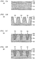
- FIGS. 4A-4D are cross-sectional side views illustrating a process for fabricating a fingered capacitor 400 according to one embodiment of the present invention.
- FIG. 4A shows a multi-layered structure 420 after a low-K dielectric layer 404, then an ultra-low-K dielectric layer 406, and then a polish stop layer 408 are formed over a bottom dielectric cap layer 402.
- the bottom dielectric cap layer 402 provides metal (e.g., copper) passivation and also functions as an etch stop layer.
- the bottom dielectric cap layer 402, which has a K value between about 3.0 and about 7.5, may be made of any suitable material, such as (without limitation) SiN, SiCN, aSiC:H, and SiC x N y H z .
- the low-K dielectric layer 404 which has a K value between about 2.5 and about 3.6 and typically about 2.7, may be made of any suitable material, such as (without limitation) SiCOH, pSiCOH, and Polyarelene (PAE).
- the ultra-low-K dielectric layer 404 which has a K value of less than about 2.5, may be made of any suitable material, such as (without limitation) Carbon doped SiO 2 , Parylene-F, Bezocycloutane (BCB), and Teflon AF.
- the polish stop layer 408, which has a K value between about 2.5 and about 4.0, may be made of any suitable material, such as (without limitation) SiOC, SiC x N y , and SiCN : H.
- FIG. 4B shows the structure 430 after trenches 409 have been etched into the polish stop layer 408, the ultralow-K dielectric layer 406, and the low-K dielectric layer 404 of FIG. 4A .
- the trenches 409, as well as the other layers of the fingered capacitor 400, can be formed using conventional photolithography techniques for fabricating integrated circuits.
- FIG. 4C shows the structure 440 after copper plating and CMP polishing have been performed to fill the trenches 409 of FIG. 4B with copper to form metal fingers 410.
- the CMP polishing removes only a portion of the polish stop layer 408 in order to provide the structure 440 with a relatively flat upper surface having relatively small metal height variation.
- the top surfaces of the metal fingers 410 are co-planar with the top surface of the polish stop layer 408.
- a liner layer is applied to the trenches 409 prior to the copper plating to function as a metal plating seed and a metal barrier layer between the metal fingers 410 and the underlying dielectric 404/406/408.
- FIG. 4D shows the fingered capacitor 400 formed by applying the top dielectric cap layer 412 over the structure 440 of FIG. 4C .
- the top dielectric cap layer 412 can be, but does not have to be, formed using the same material as the bottom dielectric cap layer 402. Additional polishing can be applied to the top dielectric cap layer 412 to make the surface flat.
- FIG. 4D is a crosssectional view of a portion of the fingered capacitor 400 corresponding to three adjacent fingers 410.
- the low-K dielectric layer 404 is formed directly over the bottom dielectric cap layer 402
- the ultra-low-K dielectric layer 406 is formed directly over the low-K dielectric layer 404
- the polish stop layer 408 is formed directly over the ultra-low-K dielectric layer 406
- the top dielectric cap layer 412 is formed directly over the polish stop layer 408.
- FIGS. 5A-5D are cross-sectional side views illustrating a process for fabricating a fingered capacitor 500 according to another embodiment of the invention.
- FIG. 5A shows a multi-layer structure 520 after a first low-K dielectric layer 504, then an ultra-low-K dielectric layer 506, then a polish stop layer 508, and then a second low-K dielectric layer 511 are formed over a bottom dielectric cap layer 502.
- the bottom dielectric cap layer 402, the first low-K dielectric layer 504, the ultra-low-K dielectric layer 506, and the polish stop layer 508 can be, but do not have to be, made of the same materials as the corresponding layers in the fingered capacitor 400 of FIG. 4D .
- the second low-K dielectric layer 511 can be, but does not have to be, made of the same material, or have the same value of K, as the first low-K dielectric layer 504.
- FIG. 5B shows the structure 530 after trenches 509 have been etched into the second low-K dielectric layer 511, the polish stop layer 508, the ultra-low-K dielectric layer 506, and the first low-K dielectric layer 504 of FIG. 5A .
- the trenches 509, as well as the other layers of the fingered capacitor 500, can be formed using conventional photolithography techniques for fabricating integrated circuits.
- FIG. 5C shows the structure 540 after copper plating and CMP polishing have been performed to fill the trenches 509 of FIG. 5B with copper to form metal fingers 510.
- the CMP polishing removes all of the second low-K dielectric layer AJ and little if any of the polish stop layer 508 in order to provide the structure 540 with a relatively flat upper surface having relatively small metal height variation.
- the second low-K dielectric layer AJ which is typically made of a material that is softer than the material of the polish stop layer 508, provides a "soft landing" for better process control during the CMP polishing step and can enable less material to be used for the polish stop layer 508.
- a liner layer is applied to the trenches 509 prior to the copper plating to function as a metal plating seed and a metal barrier layer between the metal fingers 510 and the underlying dielectric 504/506/508/511.
- the top surfaces of the metal fingers 510 are co-planar with the top surface of the polish stop layer 508.
- the structure 540 is substantially identical to the structure 440 of FIG. 4C .
- FIG. 5D shows the fingered capacitor 500 formed by applying the top dielectric cap layer 512 over the structure
- FIG. 5D is a crosssectional view of a portion of the fingered capacitor 500 corresponding to three adjacent fingers 510.
- the first low-K dielectric layer 504 is formed directly over the bottom dielectric cap layer 502
- the ultra-low-K dielectric layer 506 is formed directly over the first low-K dielectric layer 504
- the polish stop layer 508 is formed directly over the ultralow-K dielectric layer 506
- the second low-K dielectric layer 511 is formed directly over the polish stop layer 508, and, after the second low-K dielectric layer 511 is completely removed during the CMP polishing, the top dielectric cap layer 512 is formed directly over the remaining polish stop layer 508.
- FIGS. 6A-6C are cross-sectional side views illustrating a process for fabricating a fingered capacitor 600 according to yet another embodiment of the invention.
- the process of FIGS. 6A-6C can begin with either the structure 440 of FIG. 4C or the similar structure 540 of FIG. 5C .
- the following discussion is based on the process of FIGS. 6A-6C beginning with the structure 440 of FIG. 4C .
- FIG. 6A shows the structure 440 of FIG. 4C formed as described above in the context of FIGS. 6A-6C .
- FIG. 6B shows the structure 650 formed by etching away the remaining material of the polish stop layer 408 of FIG. 6A . Note that, in the structure 650, the top surfaces of the metal fingers 410 extend above the top surface of the (first) ultra-low-K dielectric layer 406.
- FIG. 6C shows the fingered capacitor 600 formed by applying a second ultra-low-K dielectric layer 611 and a top dielectric cap layer FI over the structure 650 of FIG. 6B .
- the second ultra-low-K dielectric layer 611 may be formed using the same material as the first ultra-low-K dielectric layer 406, and the top dielectric cap layer 612 can be, but does not have to be formed using the same material as the bottom dielectric cap layer 502.
- the second ultra-low-K dielectric layer 611 can further reduce overall capacitance variations by completely encapsulating the tops of the metal fingers 410 with ultra-low-K dielectric material. Additional polishing can be applied to the top dielectric cap layer 612 to make the surface flat. Analogous to FIGS.
- FIG. 6C is a crosssectional view of a portion of the fingered capacitor 600 corresponding to three adjacent fingers 510.
- the low-K dielectric layer 404 is formed directly over the bottom dielectric cap layer 402
- the first ultra-low-K dielectric layer 406 is formed directly over the low-K dielectric layer 404
- the polish stop layer 408 is formed directly over the first ultra-low-K dielectric layer 406, after the polish stop layer 408 has been completely removed
- the second ultra-low-K dielectric layer 611 is formed directly over the first ultralow-K dielectric layer 406
- the top dielectric cap layer 612 is formed directly over the second ultra-low-K dielectric layer 611.
- the present invention provides a method of fabricating a fingered capacitor that employs a polish stop layer to control the metal thickness.
- the trench is normally designed as inverted trapezoid shape for easy trench etch and metal plating, which gives shorter top metal space than that of bottom metal.
- An ultra-low-K dielectric is introduced at the top metal position to control any extra variation there. The method allows for high precision and high uniformity fringe capacitors with little process add-on.
- the polish stop layer can reduce metal height variation from CMP.
- the ultra-low-K material at the top part can reduce any extra variation caused by inverted trapezoid metal shape, and the extra ultra-low-K material re-deposition can further reduce any variation caused by inverted trapezoid metal shape.
- the invention has been described in the context of embodiments having a second dielectric layer with an ultra-low K value formed over a first dielectric layer with a low K value, in general, it may be sufficient for the K value of the second dielectric layer to be smaller than the K value of the first dielectric layer, whether or not those two layers have ultra-low and low K values, respectively.
Abstract
Description
- The present invention relates to semiconductor integrated circuit (IC) fabrication and, more particularly, to fingered capacitors.
- Fingered capacitors or fringe capacitors are commonly used in Analog-Mixed Signal (AMS) ICs.
FIG. 1 is based onFIG. 1 ofU.S. Patent No. 6,385,033 , which is a perspective view of a conventional fingeredcapacitor 100 having afirst capacitor element 120. Thefirst capacitor element 120 includes apositive metal plate 130 and anegative metal plate 140. Thepositive metal plate 130 has a comb-like structure that includes anelongated end portion 132 havingfingers 134 extending perpendicular from theend portion 132. Thenegative metal plate 140 also has a comb-like structure that includes anelongated end portion 142 havingfingers 144 extending perpendicular from theend portion 142. Thefingers respective fingers -
FIG. 2 is a cross-sectional side view of a portion of a conventional fingeredcapacitor 200, such as thefingered capacitor 100 ofFIG. 1 , along the perpendicular cut-line AA' ofFIG. 1 . In particular,FIG. 2 shows threeadjacent metal fingers 210 of thefingered capacitor 200, which would typically have one or more additional, equivalent fingers to the left and/or right of the threefingers 200. The threemetal fingers 210 inFIG. 2 could correspond to, inFIG. 1 , one of the positive-plate fingers 134 located between two negative-plate fingers 144 or one of the negative-plate fingers 144 located between two positive-plate fingers 134. The fingeredcapacitor 200 can be implemented in one metal layer of a multi-layer integrated circuit having one or more metal layers below the metal layer of thefingered capacitor 200 and/or one or more metal layers above that metal layer, but it is typically replicated across several metal layers in order to get higher fringe capacitance at the same layout area. - As shown in
FIG. 2 , thefingered capacitor 200 comprises a bottomdielectric cap layer 202 that provides copper passivation and also functions as an etch stop layer. - Above the
dielectric cap layer 202 is a low-Kdielectric layer 204. Located within "inverted-trapezoid-shaped" trenches formed in the low-Kdielectric layer 204 are copper traces that form themetal fingers 210. Covering the low-Kdielectric layer 204 and themetal fingers 210 is a topdielectric cap layer 212, upon which one or more other metal layers (not shown) may be fabricated. -
FIGS. 3A-3D are cross-sectional side views illustrating a conventional process for fabricating the fingeredcapacitor 200 ofFIG. 2 .FIG. 3A shows amulti-layer structure 320 having the low-Kdielectric layer 204 formed over thedielectric cap layer 202.FIG. 3B shows the structure - 330 after
trenches 309 have been formed in the low-Kdielectric layer 204 ofFIG. 3A using conventional photolithography techniques.FIG. 3C shows the structure 340 after (i) thetrenches 309 ofFIG. 3B have been filled with copper plating and then (ii) chemical-mechanical polishing (CMP) is performed to provide the structure 340 with a flat upper surface.FIG. 3D shows thefingered capacitor 200 formed by applying the topdielectric cap layer 212 over the structure 340 ofFIG. 3C . - As should be apparent from above, precision and uniformity across the wafer are the two key requirements of fingered capacitors. However, due to the nature of the Chemical-Mechanical-Polish (CMP) process, the metal thickness is not so easy to control. It would be advantageous to be able to better control the metal thickness.
- The invention, together with objects and advantages thereof, may best be understood by reference to the following description of the presently preferred embodiments together with the accompanying drawings in which:
-
FIG. 1 corresponds toFIG. 1 ofU.S. Patent No. 6,385,033 , which is a perspective view of a conventional fingered capacitor; -
FIG. 2 is a cross-sectional side view of a portion of a conventional fingered capacitor; -
FIGS. 3A-3D are cross-sectional side views illustrating a conventional process for fabricating the fingered capacitor ofFIG. 2 ; -
FIGS. 4A-4D are cross-sectional side views illustrating a process for fabricating a fingered capacitor according to one embodiment of the invention; -
FIGS. 5A-5D are cross-sectional side views illustrating a process for fabricating a fingered capacitor according to another embodiment of the invention; and -
FIGS. 6A-6C are cross-sectional side views illustrating a process for fabricating a fingered capacitor according to yet another embodiment of the invention. - One problem with the architecture of the conventional
fingered capacitor 200 ofFIG. 2 is the variation in the overall capacitor capacitance level that can exist for different instances of thefingered capacitor 200. The overall capacitance level of a particular instance is a function of the horizontal distances betweenadjacent fingers 210 in thefingered capacitor 200 and the metal height. Variations in those horizontal distances for different instances of the fingeredcapacitor 200 or the metal height can result in variations in the overall capacitance level for those different instances. - Due to their inverted-trapezoid shape, the horizontal distance between
adjacent metal fingers 210 is shorter at the tops of themetal fingers 210 than at their lower regions. Since shorter distance implies greater fringe capacitance, the contribution to variation in overall capacitance level is greater at the tops of themetal fingers 210 than at their lower regions.way to address this capacitance variation issue is to deploy, adjacent to the tops of the inverted-trapezoid shaped metal fingers, a dielectric material having a relative permittivity (also known as dielectric constant or K value) that is lower than the K value of the dielectric material deployed adjacent to the lower regions of those metal fingers. The lower K value of the dielectric material adjacent to the tops of the metal fingers will reduce the corresponding relative contribution to the overall capacitance level, thereby reducing the magnitude of the variation in the overall capacitance level due to variations in horizontal inter-finger distances for different instances of the fingered capacitor.
- One problem with deploying a low-K dielectric material is that the subsequently applied CMP can result in undesirable metal height variation (i.e., deviation of the polished surface from being sufficiently flat). Changing the low-K dielectric to an ultra-low-K dielectric adjacent to the tops of the metal fingers makes the problem even worse. To address this problem, a polish stop layer can be applied over the lower-K dielectric layer prior to CMP, which will typically result in the polished surface having less metal height variation. In some embodiments, at least a portion of the polish stop layer remains in the final fingered capacitor, while, in other embodiments, the entire polish stop layer is removed during the fabrication process.
- One aspect of the present invention is an integrated circuit having a plurality of fingers forming a fingered capacitor. The fingered capacitor includes a first dielectric cap layer, a first dielectric layer formed over the dielectric cap layer and having a first K value, and a second dielectric layer formed over the first dielectric layer and having a second K value lower than the first K value. The fingers are formed in the first and second dielectric layers. A second dielectric cap layer is formed over the fingers and the second dielectric layer.
- Another aspect of the present invention is a method for fabricating a fingered capacitor. The method includes forming a first dielectric cap layer, and then forming a first dielectric layer having a first K value over the dielectric cap layer. Next a second dielectric layer having a second K value lower than the first K value is formed over the first dielectric layer. Then, the fingers are formed in the first and second dielectric layers. Next, a second dielectric cap layer is formed over the fingers and the second dielectric layer.
-
FIGS. 4A-4D are cross-sectional side views illustrating a process for fabricating a fingered capacitor 400 according to one embodiment of the present invention. -
FIG. 4A shows amulti-layered structure 420 after a low-K dielectric layer 404, then an ultra-low-K dielectric layer 406, and then apolish stop layer 408 are formed over a bottomdielectric cap layer 402. The bottomdielectric cap layer 402 provides metal (e.g., copper) passivation and also functions as an etch stop layer. The bottomdielectric cap layer 402, which has a K value between about 3.0 and about 7.5, may be made of any suitable material, such as (without limitation) SiN, SiCN, aSiC:H, and SiCxNyHz. The low-K dielectric layer 404, which has a K value between about 2.5 and about 3.6 and typically about 2.7, may be made of any suitable material, such as (without limitation) SiCOH, pSiCOH, and Polyarelene (PAE). The ultra-low-K dielectric layer 404, which has a K value of less than about 2.5, may be made of any suitable material, such as (without limitation) Carbon doped SiO2, Parylene-F, Bezocycloutane (BCB), and Teflon AF. Thepolish stop layer 408, which has a K value between about 2.5 and about 4.0, may be made of any suitable material, such as (without limitation) SiOC, SiCxNy, and SiCN:H. -
FIG. 4B shows the structure 430 aftertrenches 409 have been etched into thepolish stop layer 408, the ultralow-K dielectric layer 406, and the low-K dielectric layer 404 ofFIG. 4A . Those skilled in the art will know how thetrenches 409, as well as the other layers of the fingered capacitor 400, can be formed using conventional photolithography techniques for fabricating integrated circuits. -
FIG. 4C shows the structure 440 after copper plating and CMP polishing have been performed to fill thetrenches 409 ofFIG. 4B with copper to formmetal fingers 410. Note that the CMP polishing removes only a portion of thepolish stop layer 408 in order to provide the structure 440 with a relatively flat upper surface having relatively small metal height variation. Note that, in the structure 440, the top surfaces of themetal fingers 410 are co-planar with the top surface of thepolish stop layer 408. Although not shown in the figures, a liner layer is applied to thetrenches 409 prior to the copper plating to function as a metal plating seed and a metal barrier layer between themetal fingers 410 and theunderlying dielectric 404/406/408. -
FIG. 4D shows the fingered capacitor 400 formed by applying the topdielectric cap layer 412 over the structure 440 ofFIG. 4C . The topdielectric cap layer 412 can be, but does not have to be, formed using the same material as the bottomdielectric cap layer 402. Additional polishing can be applied to the topdielectric cap layer 412 to make the surface flat. Analogous toFIG. 2 ,FIG. 4D is a crosssectional view of a portion of the fingered capacitor 400 corresponding to threeadjacent fingers 410. Here, too, there may be one or more metal layers below and/or one or more metal layers above the metal layer in which the fingered capacitor 400 is formed. - In fabricating the fingered capacitor 400, the low-
K dielectric layer 404 is formed directly over the bottomdielectric cap layer 402, the ultra-low-K dielectric layer 406 is formed directly over the low-K dielectric layer 404, thepolish stop layer 408 is formed directly over the ultra-low-K dielectric layer 406, and the topdielectric cap layer 412 is formed directly over thepolish stop layer 408. In alternative implementations, there may be one or more suitable intervening layers between one or more of these different layer pairs. Such layer(s) can enhance adhesion and/or mechanical strength. -
FIGS. 5A-5D are cross-sectional side views illustrating a process for fabricating a fingered capacitor 500 according to another embodiment of the invention. -
FIG. 5A shows a multi-layer structure 520 after a first low-K dielectric layer 504, then an ultra-low-K dielectric layer 506, then apolish stop layer 508, and then a second low-K dielectric layer 511 are formed over a bottomdielectric cap layer 502. The bottomdielectric cap layer 402, the first low-K dielectric layer 504, the ultra-low-K dielectric layer 506, and thepolish stop layer 508 can be, but do not have to be, made of the same materials as the corresponding layers in the fingered capacitor 400 ofFIG. 4D . The second low-K dielectric layer 511 can be, but does not have to be, made of the same material, or have the same value of K, as the first low-K dielectric layer 504. -
FIG. 5B shows the structure 530 aftertrenches 509 have been etched into the second low-K dielectric layer 511, thepolish stop layer 508, the ultra-low-K dielectric layer 506, and the first low-K dielectric layer 504 ofFIG. 5A . Those skilled in the art will know how thetrenches 509, as well as the other layers of the fingered capacitor 500, can be formed using conventional photolithography techniques for fabricating integrated circuits. -
FIG. 5C shows the structure 540 after copper plating and CMP polishing have been performed to fill thetrenches 509 ofFIG. 5B with copper to formmetal fingers 510. Note that the CMP polishing removes all of the second low-K dielectric layer AJ and little if any of thepolish stop layer 508 in order to provide the structure 540 with a relatively flat upper surface having relatively small metal height variation. The second low-K dielectric layer AJ, which is typically made of a material that is softer than the material of thepolish stop layer 508, provides a "soft landing" for better process control during the CMP polishing step and can enable less material to be used for thepolish stop layer 508. Although not shown in the figures, a liner layer is applied to thetrenches 509 prior to the copper plating to function as a metal plating seed and a metal barrier layer between themetal fingers 510 and theunderlying dielectric 504/506/508/511. Note that, in the structure 540, the top surfaces of themetal fingers 510 are co-planar with the top surface of thepolish stop layer 508. Note also that the structure 540 is substantially identical to the structure 440 ofFIG. 4C . -
FIG. 5D shows the fingered capacitor 500 formed by applying the topdielectric cap layer 512 over the structure - 540 of
FIG. 5C . The topdielectric cap layer 512 can be, but does not have to be, formed using the same material as the bottomdielectric cap layer 502. Additional polishing can be applied to the topdielectric cap layer 512 to make the surface flat. Analogous toFIG. 2 ,FIG. 5D is a crosssectional view of a portion of the fingered capacitor 500 corresponding to threeadjacent fingers 510. Here, too, there may be one or more metal layers below and/or one or more metal layers above the metal layer in which the fingered capacitor 500 is formed. Note that the structure of the fingered capacitor 500 is substantially identical to the structure of the fingered capacitor 400 ofFIG. 4C . - In fabricating the fingered capacitor 500, the first low-
K dielectric layer 504 is formed directly over the bottomdielectric cap layer 502, the ultra-low-K dielectric layer 506 is formed directly over the first low-K dielectric layer 504, thepolish stop layer 508 is formed directly over the ultralow-K dielectric layer 506, the second low-K dielectric layer 511 is formed directly over thepolish stop layer 508, and, after the second low-K dielectric layer 511 is completely removed during the CMP polishing, the topdielectric cap layer 512 is formed directly over the remainingpolish stop layer 508. In alternative implementations, there may be one or more suitable intervening layers between one or more of these different layer pairs. Such layer(s) can enhance adhesion and/or mechanical strength. -
FIGS. 6A-6C are cross-sectional side views illustrating a process for fabricating a fingered capacitor 600 according to yet another embodiment of the invention. The process ofFIGS. 6A-6C can begin with either the structure 440 ofFIG. 4C or the similar structure 540 ofFIG. 5C . The following discussion is based on the process ofFIGS. 6A-6C beginning with the structure 440 ofFIG. 4C . Those skilled in the art will understand how to perform an analogous process beginning with the similar structure 540 ofFIG. 5C . [00033]FIG. 6A shows the structure 440 ofFIG. 4C formed as described above in the context ofFIGS. 6A-6C . -
FIG. 6B shows the structure 650 formed by etching away the remaining material of thepolish stop layer 408 ofFIG. 6A . Note that, in the structure 650, the top surfaces of themetal fingers 410 extend above the top surface of the (first) ultra-low-K dielectric layer 406. -
FIG. 6C shows the fingered capacitor 600 formed by applying a second ultra-low-K dielectric layer 611 and a top dielectric cap layer FI over the structure 650 ofFIG. 6B . The second ultra-low-K dielectric layer 611 may be formed using the same material as the first ultra-low-K dielectric layer 406, and the topdielectric cap layer 612 can be, but does not have to be formed using the same material as the bottomdielectric cap layer 502. The second ultra-low-K dielectric layer 611 can further reduce overall capacitance variations by completely encapsulating the tops of themetal fingers 410 with ultra-low-K dielectric material. Additional polishing can be applied to the topdielectric cap layer 612 to make the surface flat. Analogous toFIGS. 2 and3 ,FIG. 6C is a crosssectional view of a portion of the fingered capacitor 600 corresponding to threeadjacent fingers 510. Here, too, there may be one or more metal layers below and/or one or more metal layers above the metal layer in which the fingered capacitor 600 is formed. - In fabricating the fingered capacitor 600, the low-
K dielectric layer 404 is formed directly over the bottomdielectric cap layer 402, the first ultra-low-K dielectric layer 406 is formed directly over the low-K dielectric layer 404, thepolish stop layer 408 is formed directly over the first ultra-low-K dielectric layer 406, after thepolish stop layer 408 has been completely removed, the second ultra-low-K dielectric layer 611 is formed directly over the first ultralow-K dielectric layer 406, and the topdielectric cap layer 612 is formed directly over the second ultra-low-K dielectric layer 611. In alternative implementations, there may be one or more suitable intervening layers between one or more of these different layer pairs. Such layer(s) can enhance adhesion and/or mechanical strength. - It should be apparent to those skilled in the art that the present invention provides a method of fabricating a fingered capacitor that employs a polish stop layer to control the metal thickness. The trench is normally designed as inverted trapezoid shape for easy trench etch and metal plating, which gives shorter top metal space than that of bottom metal. An ultra-low-K dielectric is introduced at the top metal position to control any extra variation there. The method allows for high precision and high uniformity fringe capacitors with little process add-on.
- In the present invention, the polish stop layer can reduce metal height variation from CMP. The ultra-low-K material at the top part can reduce any extra variation caused by inverted trapezoid metal shape, and the extra ultra-low-K material re-deposition can further reduce any variation caused by inverted trapezoid metal shape.
- The present invention may be embodied in many other specific forms without departing from the spirit or scope of the invention. Particularly, it should be understood that the present invention may be embodied in the following forms.
- Although the invention has been described in the context of embodiments having a second dielectric layer with an ultra-low K value formed over a first dielectric layer with a low K value, in general, it may be sufficient for the K value of the second dielectric layer to be smaller than the K value of the first dielectric layer, whether or not those two layers have ultra-low and low K values, respectively.
- Although the invention has been described in the context of metal fingers formed of copper, those skilled in the art will understand that the fingers can be formed using other suitable metals or even other suitable non-metallic conductors.
- Although the invention has been described in the context of methods for fabricating various embodiments in which CMP polishing is applied at certain steps. Those skilled in the art will understand that other suitable processes may be employed other than CMP polishing during some of those steps, such as wet or dry etching processes.
- The present examples and embodiments are to be considered as illustrative and not restrictive, and the invention is not to be limited to the details given herein, but may be modified within the scope and equivalence of the appended claims.
Claims (15)
- An integrated circuit comprising a plurality of fingers (410, 510) forming a fingered capacitor, the fingered capacitor comprising:a first dielectric cap layer (402, 502);a first dielectric layer (404, 504) formed over the dielectric cap layer and having a first K value; a second dielectric layer (406, 506) formed over the first dielectric layer and having a second K value lower than the first K value, wherein the fingers are formed in the first and second dielectric layers; anda second dielectric cap layer (412, 512, 612) formed over the fingers and the second dielectric layer.
- The integrated circuit of claim 1, wherein:the first dielectric layer is formed directly over the first dielectric cap layer; andthe second dielectric layer is formed directly over the first dielectric layer.
- The integrated circuit of claim 1 or 2, wherein the fingered capacitor further comprises a polish stop layer (408, 508) between the second dielectric layer and the second dielectric cap layer.
- The integrated circuit of claim 3, wherein the polish stop layer is formed directly over the second dielectric layer.
- The integrated circuit of claim 3, wherein the at least one of: (a) fingers also are formed in the polish stop layer, and (b) the top surfaces of the fingers are co-planar with the top surface of the polish stop layer.
- The integrated circuit of any preceding claim, wherein the fingered capacitor further comprises a third dielectric layer (611) formed over the second dielectric layer and the fingers, wherein the second dielectric cap layer is formed over the third dielectric layer.
- The integrated circuit of claim 6, wherein:
the third dielectric layer is formed directly over the second dielectric layer; and the second dielectric cap layer is formed directly over the third dielectric layer. - The integrated circuit of claim 6 or 7, wherein the top surfaces of the fingers extend above the top surface of the second dielectric layer.
- A method for fabricating a fingered capacitor comprising a plurality of fingers in an integrated circuit, the method comprising:forming a first dielectric cap layer (402, 502);
then forming a first dielectric layer (404, 504) over the dielectric cap layer and having a first K value;then forming a second dielectric layer (406, 506) over the first dielectric layer and having a second K value lower than the first K value; then forming the fingers in the first and second dielectric layers; andthen forming a second dielectric cap layer (412, 512, 612) over the fingers and the second dielectric layer. - The integrated circuit of claim 9, wherein:the first dielectric layer is formed directly over the first dielectric cap layer; andthe second dielectric layer is formed directly over the first dielectric layer.
- The method of claim 11, further comprising:
before the fingers are formed, forming a polish stop layer (408, 508) over the second dielectric layer, wherein the fingers are also formed in the polish stop layer; and after the fingers are formed, performing CMP polishing, wherein:the CMP polishing removes some, but not all of the polish stop layer; and after the CMP polishing, the top surfaces of thefingers are co-planar with the top surface of the polish stop layer. - The integrated circuit of claim 11, wherein the polish stop layer is formed directly over the second dielectric layer.
- The method of claim 11 or 12, wherein, after the CMP polishing, the second dielectric cap layer is formed over, or directly over, the polish stop layer.
- The method of any of claims 11 to 13, further comprising: after the CMP polishing, removing the remaining polish stop layer using a non-CMP polishing process; and then forming a third dielectric layer (611) over the second dielectric layer and the fingers, wherein the second dielectric cap layer is formed over the third dielectric layer.
- The method of claim 14 , wherein: the third dielectric layer is formed directly over the second dielectric layer; and the second dielectric cap layer is formed directly over the third dielectric layer.
Applications Claiming Priority (1)
| Application Number | Priority Date | Filing Date | Title |
|---|---|---|---|
| US16/141,950 US10770539B2 (en) | 2018-09-25 | 2018-09-25 | Fingered capacitor with low-K and ultra-low-K dielectric layers |
Publications (1)
| Publication Number | Publication Date |
|---|---|
| EP3629391A1 true EP3629391A1 (en) | 2020-04-01 |
Family
ID=67997350
Family Applications (1)
| Application Number | Title | Priority Date | Filing Date |
|---|---|---|---|
| EP19197724.8A Withdrawn EP3629391A1 (en) | 2018-09-25 | 2019-09-17 | Fingered capacitor with low-k and ultra-low-k dielectric layers |
Country Status (3)
| Country | Link |
|---|---|
| US (2) | US10770539B2 (en) |
| EP (1) | EP3629391A1 (en) |
| CN (1) | CN110943165A (en) |
Families Citing this family (2)
| Publication number | Priority date | Publication date | Assignee | Title |
|---|---|---|---|---|
| US10770539B2 (en) * | 2018-09-25 | 2020-09-08 | Nxp B.V. | Fingered capacitor with low-K and ultra-low-K dielectric layers |
| CN114136504B (en) * | 2021-11-29 | 2023-12-12 | 杭州电子科技大学温州研究院有限公司 | Capacitive flexible pressure sensor and preparation method thereof |
Citations (4)
| Publication number | Priority date | Publication date | Assignee | Title |
|---|---|---|---|---|
| US20020038903A1 (en) * | 2000-10-03 | 2002-04-04 | Liming Tsau | High density metal capacitor using dual-damascene copper interconnect |
| US6385033B1 (en) | 2000-09-29 | 2002-05-07 | Intel Corporation | Fingered capacitor in an integrated circuit |
| US6531777B1 (en) * | 2000-06-22 | 2003-03-11 | Advanced Micro Devices, Inc. | Barrier metal integrity testing using a dual level line to line leakage testing pattern and partial CMP |
| US20150262912A1 (en) * | 2014-03-14 | 2015-09-17 | Taiwan Semiconductor Manufacturing Company, Ltd. | Via Corner Engineering in Trench-First Dual Damascene Process |
Family Cites Families (22)
| Publication number | Priority date | Publication date | Assignee | Title |
|---|---|---|---|---|
| US5939766A (en) * | 1996-07-24 | 1999-08-17 | Advanced Micro Devices, Inc. | High quality capacitor for sub-micrometer integrated circuits |
| US5776660A (en) * | 1996-09-16 | 1998-07-07 | International Business Machines Corporation | Fabrication method for high-capacitance storage node structures |
| US6043146A (en) * | 1998-07-27 | 2000-03-28 | Motorola, Inc. | Process for forming a semiconductor device |
| US6677637B2 (en) * | 1999-06-11 | 2004-01-13 | International Business Machines Corporation | Intralevel decoupling capacitor, method of manufacture and testing circuit of the same |
| TW548779B (en) * | 2002-08-09 | 2003-08-21 | Acer Labs Inc | Integrated capacitor and method of making same |
| US6838355B1 (en) * | 2003-08-04 | 2005-01-04 | International Business Machines Corporation | Damascene interconnect structures including etchback for low-k dielectric materials |
| US6949781B2 (en) * | 2003-10-10 | 2005-09-27 | Taiwan Semiconductor Manufacturing Co. Ltd. | Metal-over-metal devices and the method for manufacturing same |
| US7259956B2 (en) * | 2003-12-19 | 2007-08-21 | Broadcom Corporation | Scalable integrated circuit high density capacitors |
| TWI229354B (en) * | 2003-12-31 | 2005-03-11 | Via Tech Inc | Capacitor pair structure for increasing the match thereof |
| US7050290B2 (en) * | 2004-01-30 | 2006-05-23 | Taiwan Semiconductor Manufacturing Company, Ltd. | Integrated capacitor |
| TWI321842B (en) * | 2006-12-05 | 2010-03-11 | Via Tech Inc | Capacitor structure for integrated circuit |
| US8207569B2 (en) * | 2007-06-06 | 2012-06-26 | Qualcomm, Incorporated | Intertwined finger capacitors |
| US8847466B2 (en) * | 2008-06-19 | 2014-09-30 | Nxp B.V. | Piezoelectric bimorph switch |
| US8716778B2 (en) * | 2008-11-17 | 2014-05-06 | Altera Corporation | Metal-insulator-metal capacitors |
| US7999300B2 (en) * | 2009-01-28 | 2011-08-16 | Globalfoundries Singapore Pte. Ltd. | Memory cell structure and method for fabrication thereof |
| US9490165B2 (en) * | 2010-12-30 | 2016-11-08 | Globalfoundries Singapore Pte. Ltd. | Reliable interconnect integration scheme |
| US8987862B2 (en) * | 2011-01-12 | 2015-03-24 | Freescale Semiconductor, Inc. | Methods of forming semiconductor devices having conductors with different dimensions |
| KR101596460B1 (en) * | 2011-10-01 | 2016-02-26 | 인텔 코포레이션 | On-chip capacitors and methods of assembling same |
| US9520461B1 (en) * | 2015-08-28 | 2016-12-13 | Texas Instruments Incorporated | Integrated circuit with lateral flux capacitor |
| KR102324172B1 (en) * | 2017-11-21 | 2021-11-08 | 삼성전자주식회사 | Semiconductor device, layout design method for the same and method for fabricating the same |
| US10770539B2 (en) * | 2018-09-25 | 2020-09-08 | Nxp B.V. | Fingered capacitor with low-K and ultra-low-K dielectric layers |
| US11114373B1 (en) * | 2020-02-26 | 2021-09-07 | Taiwan Semiconductor Manufacturing Co., Ltd. | Metal-insulator-metal structure |
-
2018
- 2018-09-25 US US16/141,950 patent/US10770539B2/en active Active
-
2019
- 2019-09-17 EP EP19197724.8A patent/EP3629391A1/en not_active Withdrawn
- 2019-09-25 CN CN201910915854.5A patent/CN110943165A/en active Pending
-
2020
- 2020-07-29 US US16/941,654 patent/US11404532B2/en active Active
Patent Citations (4)
| Publication number | Priority date | Publication date | Assignee | Title |
|---|---|---|---|---|
| US6531777B1 (en) * | 2000-06-22 | 2003-03-11 | Advanced Micro Devices, Inc. | Barrier metal integrity testing using a dual level line to line leakage testing pattern and partial CMP |
| US6385033B1 (en) | 2000-09-29 | 2002-05-07 | Intel Corporation | Fingered capacitor in an integrated circuit |
| US20020038903A1 (en) * | 2000-10-03 | 2002-04-04 | Liming Tsau | High density metal capacitor using dual-damascene copper interconnect |
| US20150262912A1 (en) * | 2014-03-14 | 2015-09-17 | Taiwan Semiconductor Manufacturing Company, Ltd. | Via Corner Engineering in Trench-First Dual Damascene Process |
Also Published As
| Publication number | Publication date |
|---|---|
| US20200098850A1 (en) | 2020-03-26 |
| US20200357881A1 (en) | 2020-11-12 |
| US10770539B2 (en) | 2020-09-08 |
| CN110943165A (en) | 2020-03-31 |
| US11404532B2 (en) | 2022-08-02 |
Similar Documents
| Publication | Publication Date | Title |
|---|---|---|
| US6782512B2 (en) | Fabrication method for a semiconductor device with dummy patterns | |
| WO2019091421A1 (en) | Interconnection structure of metal lines, method of fabricating the same and semiconductor device | |
| US8664113B2 (en) | Multilayer interconnect structure and method for integrated circuits | |
| US10636698B2 (en) | Skip via structures | |
| US10861705B2 (en) | Reduction of line wiggling | |
| KR100417366B1 (en) | Semiconductor device, method of manufacturing the same and method of designing the same | |
| US11404532B2 (en) | Fingered capacitor with low-k and ultra-low-k dielectric layers | |
| US9711447B1 (en) | Self-aligned lithographic patterning with variable spacings | |
| US10163690B2 (en) | 2-D interconnections for integrated circuits | |
| US6815820B2 (en) | Method for forming a semiconductor interconnect with multiple thickness | |
| KR101701573B1 (en) | Bi-layer hard mask for robust metalization profile | |
| US8669661B2 (en) | Metal line and via formation using hard masks | |
| TWI717173B (en) | Memory devices and methods for forming the same | |
| US20160365314A1 (en) | Capacitors | |
| US10192824B2 (en) | Edge structure for multiple layers of devices, and method for fabricating the same | |
| US10186491B2 (en) | Integrated circuit chip reinforced against front side deprocessing attacks | |
| US5854130A (en) | Method of forming multilevel interconnects in semiconductor devices | |
| US11101170B2 (en) | Dual airgap structure | |
| US20230197603A1 (en) | Electronic devices with a low dielectric constant | |
| CN102412198B (en) | Semiconductor device fabrication method | |
| US20060199369A1 (en) | Ribs for line collapse prevention in damascene structures | |
| TWI550873B (en) | Semiconductor device and method of fabricating the same |
Legal Events
| Date | Code | Title | Description |
|---|---|---|---|
| PUAI | Public reference made under article 153(3) epc to a published international application that has entered the european phase |
Free format text: ORIGINAL CODE: 0009012 |
|
| STAA | Information on the status of an ep patent application or granted ep patent |
Free format text: STATUS: THE APPLICATION HAS BEEN PUBLISHED |
|
| AK | Designated contracting states |
Kind code of ref document: A1 Designated state(s): AL AT BE BG CH CY CZ DE DK EE ES FI FR GB GR HR HU IE IS IT LI LT LU LV MC MK MT NL NO PL PT RO RS SE SI SK SM TR |
|
| AX | Request for extension of the european patent |
Extension state: BA ME |
|
| STAA | Information on the status of an ep patent application or granted ep patent |
Free format text: STATUS: REQUEST FOR EXAMINATION WAS MADE |
|
| 17P | Request for examination filed |
Effective date: 20201001 |
|
| RBV | Designated contracting states (corrected) |
Designated state(s): AL AT BE BG CH CY CZ DE DK EE ES FI FR GB GR HR HU IE IS IT LI LT LU LV MC MK MT NL NO PL PT RO RS SE SI SK SM TR |
|
| STAA | Information on the status of an ep patent application or granted ep patent |
Free format text: STATUS: EXAMINATION IS IN PROGRESS |
|
| 17Q | First examination report despatched |
Effective date: 20220214 |
|
| STAA | Information on the status of an ep patent application or granted ep patent |
Free format text: STATUS: THE APPLICATION IS DEEMED TO BE WITHDRAWN |
|
| 18D | Application deemed to be withdrawn |
Effective date: 20220625 |