EP3629056B1 - Object detection sensor alignment - Google Patents
Object detection sensor alignment Download PDFInfo
- Publication number
- EP3629056B1 EP3629056B1 EP19193777.0A EP19193777A EP3629056B1 EP 3629056 B1 EP3629056 B1 EP 3629056B1 EP 19193777 A EP19193777 A EP 19193777A EP 3629056 B1 EP3629056 B1 EP 3629056B1
- Authority
- EP
- European Patent Office
- Prior art keywords
- lidar sensor
- alignment markers
- indication
- reflective
- panel
- Prior art date
- Legal status (The legal status is an assumption and is not a legal conclusion. Google has not performed a legal analysis and makes no representation as to the accuracy of the status listed.)
- Active
Links
Images


Classifications
-
- B—PERFORMING OPERATIONS; TRANSPORTING
- B60—VEHICLES IN GENERAL
- B60K—ARRANGEMENT OR MOUNTING OF PROPULSION UNITS OR OF TRANSMISSIONS IN VEHICLES; ARRANGEMENT OR MOUNTING OF PLURAL DIVERSE PRIME-MOVERS IN VEHICLES; AUXILIARY DRIVES FOR VEHICLES; INSTRUMENTATION OR DASHBOARDS FOR VEHICLES; ARRANGEMENTS IN CONNECTION WITH COOLING, AIR INTAKE, GAS EXHAUST OR FUEL SUPPLY OF PROPULSION UNITS IN VEHICLES
- B60K31/00—Vehicle fittings, acting on a single sub-unit only, for automatically controlling vehicle speed, i.e. preventing speed from exceeding an arbitrarily established velocity or maintaining speed at a particular velocity, as selected by the vehicle operator
- B60K31/0008—Vehicle fittings, acting on a single sub-unit only, for automatically controlling vehicle speed, i.e. preventing speed from exceeding an arbitrarily established velocity or maintaining speed at a particular velocity, as selected by the vehicle operator including means for detecting potential obstacles in vehicle path
-
- G—PHYSICS
- G01—MEASURING; TESTING
- G01B—MEASURING LENGTH, THICKNESS OR SIMILAR LINEAR DIMENSIONS; MEASURING ANGLES; MEASURING AREAS; MEASURING IRREGULARITIES OF SURFACES OR CONTOURS
- G01B11/00—Measuring arrangements characterised by the use of optical techniques
- G01B11/002—Measuring arrangements characterised by the use of optical techniques for measuring two or more coordinates
-
- G—PHYSICS
- G01—MEASURING; TESTING
- G01S—RADIO DIRECTION-FINDING; RADIO NAVIGATION; DETERMINING DISTANCE OR VELOCITY BY USE OF RADIO WAVES; LOCATING OR PRESENCE-DETECTING BY USE OF THE REFLECTION OR RERADIATION OF RADIO WAVES; ANALOGOUS ARRANGEMENTS USING OTHER WAVES
- G01S13/00—Systems using the reflection or reradiation of radio waves, e.g. radar systems; Analogous systems using reflection or reradiation of waves whose nature or wavelength is irrelevant or unspecified
- G01S13/88—Radar or analogous systems specially adapted for specific applications
- G01S13/93—Radar or analogous systems specially adapted for specific applications for anti-collision purposes
- G01S13/931—Radar or analogous systems specially adapted for specific applications for anti-collision purposes of land vehicles
-
- G—PHYSICS
- G01—MEASURING; TESTING
- G01S—RADIO DIRECTION-FINDING; RADIO NAVIGATION; DETERMINING DISTANCE OR VELOCITY BY USE OF RADIO WAVES; LOCATING OR PRESENCE-DETECTING BY USE OF THE REFLECTION OR RERADIATION OF RADIO WAVES; ANALOGOUS ARRANGEMENTS USING OTHER WAVES
- G01S15/00—Systems using the reflection or reradiation of acoustic waves, e.g. sonar systems
- G01S15/88—Sonar systems specially adapted for specific applications
- G01S15/93—Sonar systems specially adapted for specific applications for anti-collision purposes
- G01S15/931—Sonar systems specially adapted for specific applications for anti-collision purposes of land vehicles
-
- G—PHYSICS
- G01—MEASURING; TESTING
- G01S—RADIO DIRECTION-FINDING; RADIO NAVIGATION; DETERMINING DISTANCE OR VELOCITY BY USE OF RADIO WAVES; LOCATING OR PRESENCE-DETECTING BY USE OF THE REFLECTION OR RERADIATION OF RADIO WAVES; ANALOGOUS ARRANGEMENTS USING OTHER WAVES
- G01S17/00—Systems using the reflection or reradiation of electromagnetic waves other than radio waves, e.g. lidar systems
- G01S17/86—Combinations of lidar systems with systems other than lidar, radar or sonar, e.g. with direction finders
-
- G—PHYSICS
- G01—MEASURING; TESTING
- G01S—RADIO DIRECTION-FINDING; RADIO NAVIGATION; DETERMINING DISTANCE OR VELOCITY BY USE OF RADIO WAVES; LOCATING OR PRESENCE-DETECTING BY USE OF THE REFLECTION OR RERADIATION OF RADIO WAVES; ANALOGOUS ARRANGEMENTS USING OTHER WAVES
- G01S17/00—Systems using the reflection or reradiation of electromagnetic waves other than radio waves, e.g. lidar systems
- G01S17/88—Lidar systems specially adapted for specific applications
- G01S17/93—Lidar systems specially adapted for specific applications for anti-collision purposes
- G01S17/931—Lidar systems specially adapted for specific applications for anti-collision purposes of land vehicles
-
- G—PHYSICS
- G01—MEASURING; TESTING
- G01S—RADIO DIRECTION-FINDING; RADIO NAVIGATION; DETERMINING DISTANCE OR VELOCITY BY USE OF RADIO WAVES; LOCATING OR PRESENCE-DETECTING BY USE OF THE REFLECTION OR RERADIATION OF RADIO WAVES; ANALOGOUS ARRANGEMENTS USING OTHER WAVES
- G01S7/00—Details of systems according to groups G01S13/00, G01S15/00, G01S17/00
- G01S7/02—Details of systems according to groups G01S13/00, G01S15/00, G01S17/00 of systems according to group G01S13/00
- G01S7/40—Means for monitoring or calibrating
-
- G—PHYSICS
- G01—MEASURING; TESTING
- G01S—RADIO DIRECTION-FINDING; RADIO NAVIGATION; DETERMINING DISTANCE OR VELOCITY BY USE OF RADIO WAVES; LOCATING OR PRESENCE-DETECTING BY USE OF THE REFLECTION OR RERADIATION OF RADIO WAVES; ANALOGOUS ARRANGEMENTS USING OTHER WAVES
- G01S7/00—Details of systems according to groups G01S13/00, G01S15/00, G01S17/00
- G01S7/02—Details of systems according to groups G01S13/00, G01S15/00, G01S17/00 of systems according to group G01S13/00
- G01S7/40—Means for monitoring or calibrating
- G01S7/4004—Means for monitoring or calibrating of parts of a radar system
- G01S7/4026—Antenna boresight
-
- G—PHYSICS
- G01—MEASURING; TESTING
- G01S—RADIO DIRECTION-FINDING; RADIO NAVIGATION; DETERMINING DISTANCE OR VELOCITY BY USE OF RADIO WAVES; LOCATING OR PRESENCE-DETECTING BY USE OF THE REFLECTION OR RERADIATION OF RADIO WAVES; ANALOGOUS ARRANGEMENTS USING OTHER WAVES
- G01S7/00—Details of systems according to groups G01S13/00, G01S15/00, G01S17/00
- G01S7/48—Details of systems according to groups G01S13/00, G01S15/00, G01S17/00 of systems according to group G01S17/00
- G01S7/481—Constructional features, e.g. arrangements of optical elements
-
- G—PHYSICS
- G01—MEASURING; TESTING
- G01S—RADIO DIRECTION-FINDING; RADIO NAVIGATION; DETERMINING DISTANCE OR VELOCITY BY USE OF RADIO WAVES; LOCATING OR PRESENCE-DETECTING BY USE OF THE REFLECTION OR RERADIATION OF RADIO WAVES; ANALOGOUS ARRANGEMENTS USING OTHER WAVES
- G01S7/00—Details of systems according to groups G01S13/00, G01S15/00, G01S17/00
- G01S7/48—Details of systems according to groups G01S13/00, G01S15/00, G01S17/00 of systems according to group G01S17/00
- G01S7/497—Means for monitoring or calibrating
- G01S7/4972—Alignment of sensor
Definitions
- cruise control systems may incorporate light detection and ranging (LiDAR) for detecting an object or another vehicle in the pathway of a vehicle.
- LiDAR light detection and ranging
- the cruise control setting may be automatically adjusted to reduce the speed of the vehicle based on detecting another vehicle in the pathway of the vehicle.
- US 2017/0003141 A1 discloses a movable calibration fixture mounted separately from a vehicle, said fixture having a front panel that is non-transparent to radiation emitted from a range-finding sensor.
- EP 3 180 636 A1 and DE 10 2011 120 535 A1 disclose calibration targets that are positioned separate from a vehicle.
- US 2009/033926 A1 discloses a device for calibrating at least one image sensor system connected to a motor vehicle by using at least one calibration object, wherein the calibration object is situated on the inside of an engine hood of the vehicle.
- US 2017/336496 A1 discloses a moveable body which allows detection of an axial deviation of an axis of a surroundings detector such as a camera or a radar using a marker.
- LiDAR sensors are useful there are challenges associated with their use. For example, it is necessary to ensure proper calibration and positioning of the sensor over time.
- An illustrative example object detection system as set out in claim 1 includes a LiDAR sensor installed on a vehicle having a field of view.
- the LiDAR sensor is configured to emit radiation and to detect at least some of the radiation reflected by an object within the field of view.
- a panel is installed on the vehicle in the field of view, wherein the panel is a windshield of the vehicle that is transparent to the radiation emitted by the LiDAR sensor.
- the panel is configured to be set in a fixed position relative to a vehicle coordinate system.
- a plurality of reflective alignment markers are situated on the panel in the field of view. The reflective alignment markers reflect radiation emitted by the LiDAR sensor back toward the LiDAR sensor.
- a processor is configured to determine an alignment of the LiDAR sensor with the vehicle coordinate system based on an indication from the LiDAR sensor regarding radiation reflected by the reflective alignment markers and detected by the LiDAR sensor.
- Embodiments of this invention provide the ability to monitor the alignment of an object detection sensor with a vehicle coordinate system, which serves as a frame of reference. Reflective alignment markers in the field of view of the sensor allow the sensor to provide an indication of an alignment of the sensor field of view with the vehicle coordinate system.
- Figures 1 and 2 schematically illustrate an object detection system 20 associated with a vehicle 22.
- the object detection system 20 is used to provide driver-assist features while, in other embodiments, the object detection system 20 is used for autonomous vehicle operation.
- the object detection system 20 includes a sensor 24 that has a field of view 26 for detecting objects in a vicinity or pathway of the vehicle 22.
- the sensor is a LiDAR sensor.
- the radiation emitted by such a sensor comprises light.
- Other sensor configurations that include other types of radiation are used in some example embodiments.
- the sensor 24 is situated near a panel 28, which in Figure 1 is a windshield of the vehicle 22.
- the panel 28 remains in a fixed position relative to a vehicle coordinate system 30.
- the panel 28 is transparent to radiation emitted by the sensor 24 as schematically shown at 34 in Figure 2 . When such radiation reflects off an object 36, the system 20 is capable of providing information regarding such an object including, for example, its position relative to the vehicle 22.
- a plurality of reflective alignment markers 32 are situated on the panel 28 in fixed positions that remain constant relative to the panel 28 and the vehicle coordinate system 30.
- the reflective alignment markers 32 are within the field of view 26 of the sensor 24.
- the reflective alignment markers 32 reflect at least some of the radiation emitted by the sensor 24 as schematically shown at 36. Such reflected radiation is detected by the sensor 24 and provides an indication of the orientation of the sensor 24 and its field of view 26 with respect to the vehicle coordinate system 30.
- a processor 38 is configured to determine an alignment of the sensor 24 with the vehicle coordinate system 30 based on an indication from the sensor 24 regarding the radiation 36 reflected by the reflective alignment markers 32 as such radiation 36 is detected by the sensor 24.
- the panel 28 comprises a first material that is essentially transparent to the radiation emitted by the sensor 24.
- the reflective alignment markers are established by a surface treatment on corresponding portions of the panel 28, such as etching or through micro-optical surface shaping to create a reflective grating or pattern on the panel 28.
- the gratings or patterns are shaped to enhance focusing the reflected radiation toward the sensor 24 due to the relatively short distance between the panel 28 and the sensor 24.
- the reflective alignment markers 32 remain in a fixed position on the panel 28 and the panel 28 remains in a fixed position with respect to the vehicle coordinate system 30, the reflective alignment markers 32 provide a reference to allow the processor 38 to determine whether the sensor 24 is properly aligned with the vehicle coordinate system 30. For example, over time a sensor position may change as a result of vibration or impact.
- the processor 38 is capable of determining when such misalignment has occurred and provides an output indicating a need for sensor pose compensation, sensor service or including an alert or alarm regarding the sensor misalignment condition.
- sensor pose compensation is accomplished through software, using an actuator or both.
- FIG. 3 schematically illustrates an example arrangement of reflective alignment markers 32.
- the alignment markers 32 are in a generally trapezoidal configuration.
- a first one of the alignment markers 32A is situated as a horizontal line segment and is parallel to a second alignment marker 32B.
- a third alignment marker 32C is situated generally vertical and at an oblique angle relative to the alignment markers 32A and 32B.
- a fourth alignment marker 32D is generally vertical and situated at an oblique angle relative to the alignment markers 32A and 32B.
- the field of vision 26 of the sensor 24 is and the relative positions between the sensor 24 and the windshield panel 28 result in the sensor 24 detecting the reflective alignment markers 32 in a way that results in a rectangular output schematically shown at 40 in Figure 4 from the sensor 24.
- the field of view 26, in this example is effectively framed by the reflective alignment markers 32A-32D with any objects 36 within the field of view 26 situated within that frame.
- the reflective alignment markers, in this example border the periphery of the field of view 26 when the sensor 24 is properly aligned with the vehicle coordinate system 30.
- the sensor 24 provides an indication of the positions of the reflective alignment markers 32 within the field of view 26 in a manner that is recognizable by the processor 38 for making a determination regarding the alignment of the sensor 24 with the vehicle coordinate system 30.
- the indication regarding the radiation reflected at 36 from the reflective alignment markers 32 is a first, predetermined indication, such as bordering the field of view 26, when the sensor 24 is properly aligned with the vehicle coordinate system 30.
- a second, different indication from the sensor 24 is the result of any misalignment between the sensor 24 and the vehicle coordinate system 30.
- the processor 38 in such embodiments, is programmed or configured to compare the indication from the sensor 24 regarding the radiation 36 reflected by the reflective alignment markers 32 to the first indication and to recognize any difference from that as an indication that there is some misalignment.
- Figure 5 illustrates an example sensor output when the alignment markers 30 include relatively small rectangular segments situated near corners of the field of view 26.
- the field of view 26 is generally rectangular.
- only three reflective alignment markers 32A, 32B, and 32C are provided. Having at least two of those alignment markers aligned with each other along a generally horizontal line and two of the reflective alignment markers situated relative to each other in alignment along a generally vertical line allows for the processor 38 to make a determination regarding the alignment of the sensor 24 in two dimensions.
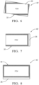
- FIG. 6 schematically shows a situation in which the field of view 26 is tilted relative to the frame established by the alignment markers 32. Under such conditions, instead of the alignments markers 32 establishing a frame around the border of the field of view 26, only portions of the alignment markers appear in the image information from the sensor 24 and those portions are not properly aligned with the borders of the field of view 26. As schematically shown in Figure 6 , portions of the reflective alignment markers 32 are outside the field of view 26 and do not appear in the sensor output 40' shown in Figure 6 .
- FIG. 7 Another example condition in which the sensor 24 is misaligned with the vehicle coordinate system 30 is schematically represented in Figure 7 .
- the sensor 24 has been shifted to the right (according to the illustration) compared to a proper installation position of the sensor 24.
- the sensor may have been rotated about a vertical axis slightly to the right (again, according to the illustration).
- the sensor output 40' does not include all of the reflective alignment markers 32.
- the reflective alignment marker 32 that should border the left side of the field of view 26 is not within the field of view 26.
- the reflective alignment marker 32 that should border the right side of the field of view 26 appears inward inside the field of view to the left of the right border of the field of view 26.
- FIG. 8 Another misalignment situation that can be determined using an embodiment of this invention is schematically shown in Figure 8 .
- the sensor 24 has been tilted relative to the panel 28 such that the frame or border provided by the radiation reflected by the reflective alignment markers 32 appears shorter than the field of view 26.
- the indication of the alignment marker that should be bordering the bottom edge of the field of view 26 appears to be shifted upward making the frame height less than the height of the field of view 26.
- the processor 38 is programmed to recognize any of the misalignment conditions shown in Figures 6, 7, and 8 along with other potential misalignment conditions.
- the reflective alignment markers 32 include a concave reflecting surface that focuses the radiation 36 reflected by the alignment markers 32 back toward the sensor 24. Providing a focusing surface enhances the ability of the sensor 24 to properly detect the reflected radiation at 36, which might otherwise introduce some challenges because the alignment markers 32 are relatively close to the sensor 24.
- the way in which the sensor 24 provides an indication of the position of the alignment markers 32 relative to the field of view 26 may vary depending on the particular embodiment.
- the intensity of the reflected radiation is greater when reflected by the reflective alignment markers 32 compared to that reflected by objects 36 at a further distance from the sensor 24.
- Other examples include using a time of flight or time difference information between emitted radiation pulses and the detected reflected radiation. The much closer position of the alignment markers 32 results in a much shorter time of flight or time difference compared to that associated with objects further from the sensor 24.
- the processor 38 is programmed or otherwise configured to recognize the indication from the sensor 24 to determine the position of the reflective alignment markers 32 relative to the field of view 26.
Landscapes
- Engineering & Computer Science (AREA)
- Remote Sensing (AREA)
- Radar, Positioning & Navigation (AREA)
- Physics & Mathematics (AREA)
- General Physics & Mathematics (AREA)
- Computer Networks & Wireless Communication (AREA)
- Electromagnetism (AREA)
- Chemical & Material Sciences (AREA)
- Mechanical Engineering (AREA)
- Transportation (AREA)
- Combustion & Propulsion (AREA)
- Acoustics & Sound (AREA)
- Length Measuring Devices By Optical Means (AREA)
- Optical Radar Systems And Details Thereof (AREA)
Description
- Advances in electronics and technology have made it possible to incorporate a variety of advanced features on automotive vehicles. Various sensing technologies have been developed for detecting objects in a vicinity or pathway of a vehicle. Such systems are useful for parking assist and cruise control adjustment features, for example.
- More recently, automated vehicle features have become possible to allow for autonomous or semi-autonomous vehicle control. For example, cruise control systems may incorporate light detection and ranging (LiDAR) for detecting an object or another vehicle in the pathway of a vehicle. Depending on the approach speed, the cruise control setting may be automatically adjusted to reduce the speed of the vehicle based on detecting another vehicle in the pathway of the vehicle.
-
US 2017/0003141 A1 discloses a movable calibration fixture mounted separately from a vehicle, said fixture having a front panel that is non-transparent to radiation emitted from a range-finding sensor.EP 3 180 636 A1 andDE 10 2011 120 535 A1 disclose calibration targets that are positioned separate from a vehicle.US 2009/033926 A1 discloses a device for calibrating at least one image sensor system connected to a motor vehicle by using at least one calibration object, wherein the calibration object is situated on the inside of an engine hood of the vehicle.US 2017/336496 A1 discloses a moveable body which allows detection of an axial deviation of an axis of a surroundings detector such as a camera or a radar using a marker. - While LiDAR sensors are useful there are challenges associated with their use. For example, it is necessary to ensure proper calibration and positioning of the sensor over time.
- An illustrative example object detection system as set out in
claim 1 includes a LiDAR sensor installed on a vehicle having a field of view. The LiDAR sensor is configured to emit radiation and to detect at least some of the radiation reflected by an object within the field of view. A panel is installed on the vehicle in the field of view, wherein the panel is a windshield of the vehicle that is transparent to the radiation emitted by the LiDAR sensor. The panel is configured to be set in a fixed position relative to a vehicle coordinate system. A plurality of reflective alignment markers are situated on the panel in the field of view. The reflective alignment markers reflect radiation emitted by the LiDAR sensor back toward the LiDAR sensor. A processor is configured to determine an alignment of the LiDAR sensor with the vehicle coordinate system based on an indication from the LiDAR sensor regarding radiation reflected by the reflective alignment markers and detected by the LiDAR sensor. - Various features and advantages of at least one disclosed example embodiment will become apparent to those skilled in the art from the following detailed description. The drawings that accompany the detailed description can be briefly described as follows.
-
-
Figure 1 diagrammatically illustrates a vehicle including an object detection system designed according to an embodiment of this invention. -
Figure 2 illustrates selected features of an example embodiment from a perspective along the lines 2-2 inFigure 1 . -
Figure 3 schematically illustrates an example arrangement of reflective alignment markers according to an embodiment of this invention. -
Figure 4 schematically illustrates an example sensor output including an indication of an orientation of alignment markers with a field of view of the sensor according to an embodiment of this invention. -
Figure 5 schematically illustrates another example sensor output including an indication of an orientation of alignment markers with a field of view of the sensor according to an embodiment of this invention. -
Figure 6 schematically illustrates an example sensor misalignment condition. -
Figure 7 schematically illustrates another example sensor misalignment condition. -
Figure 8 schematically illustrates another example sensor misalignment condition. - Embodiments of this invention provide the ability to monitor the alignment of an object detection sensor with a vehicle coordinate system, which serves as a frame of reference. Reflective alignment markers in the field of view of the sensor allow the sensor to provide an indication of an alignment of the sensor field of view with the vehicle coordinate system.
-
Figures 1 and 2 schematically illustrate anobject detection system 20 associated with avehicle 22. In some example embodiments, theobject detection system 20 is used to provide driver-assist features while, in other embodiments, theobject detection system 20 is used for autonomous vehicle operation. - The
object detection system 20 includes asensor 24 that has a field ofview 26 for detecting objects in a vicinity or pathway of thevehicle 22. The sensor is a LiDAR sensor. The radiation emitted by such a sensor comprises light. Other sensor configurations that include other types of radiation are used in some example embodiments. Thesensor 24 is situated near apanel 28, which inFigure 1 is a windshield of thevehicle 22. Thepanel 28 remains in a fixed position relative to avehicle coordinate system 30. Thepanel 28 is transparent to radiation emitted by thesensor 24 as schematically shown at 34 inFigure 2 . When such radiation reflects off anobject 36, thesystem 20 is capable of providing information regarding such an object including, for example, its position relative to thevehicle 22. - A plurality of
reflective alignment markers 32 are situated on thepanel 28 in fixed positions that remain constant relative to thepanel 28 and thevehicle coordinate system 30. When thesensor 24 is set in a desired position and orientation relative to thepanel 28, thereflective alignment markers 32 are within the field ofview 26 of thesensor 24. Thereflective alignment markers 32 reflect at least some of the radiation emitted by thesensor 24 as schematically shown at 36. Such reflected radiation is detected by thesensor 24 and provides an indication of the orientation of thesensor 24 and its field ofview 26 with respect to thevehicle coordinate system 30. Aprocessor 38 is configured to determine an alignment of thesensor 24 with thevehicle coordinate system 30 based on an indication from thesensor 24 regarding theradiation 36 reflected by thereflective alignment markers 32 assuch radiation 36 is detected by thesensor 24. - The
panel 28 comprises a first material that is essentially transparent to the radiation emitted by thesensor 24. - According to the invention , the reflective alignment markers are established by a surface treatment on corresponding portions of the
panel 28, such as etching or through micro-optical surface shaping to create a reflective grating or pattern on thepanel 28. The gratings or patterns are shaped to enhance focusing the reflected radiation toward thesensor 24 due to the relatively short distance between thepanel 28 and thesensor 24. - Since the
reflective alignment markers 32 remain in a fixed position on thepanel 28 and thepanel 28 remains in a fixed position with respect to thevehicle coordinate system 30, thereflective alignment markers 32 provide a reference to allow theprocessor 38 to determine whether thesensor 24 is properly aligned with thevehicle coordinate system 30. For example, over time a sensor position may change as a result of vibration or impact. Theprocessor 38 is capable of determining when such misalignment has occurred and provides an output indicating a need for sensor pose compensation, sensor service or including an alert or alarm regarding the sensor misalignment condition. In example embodiments, sensor pose compensation is accomplished through software, using an actuator or both. -
Figure 3 schematically illustrates an example arrangement ofreflective alignment markers 32. In this example, given the orientation of thewindshield panel 28 relative to thesensor 24 and the shape of thewindshield panel 28, thealignment markers 32 are in a generally trapezoidal configuration. A first one of the alignment markers 32A is situated as a horizontal line segment and is parallel to a second alignment marker 32B. A third alignment marker 32C is situated generally vertical and at an oblique angle relative to the alignment markers 32A and 32B. A fourth alignment marker 32D is generally vertical and situated at an oblique angle relative to the alignment markers 32A and 32B. - Although the actual, physical orientation of the
alignment markers 32 shown inFigure 3 is not truly rectangular, the field ofvision 26 of thesensor 24 is and the relative positions between thesensor 24 and thewindshield panel 28 result in thesensor 24 detecting thereflective alignment markers 32 in a way that results in a rectangular output schematically shown at 40 inFigure 4 from thesensor 24. The field ofview 26, in this example, is effectively framed by the reflective alignment markers 32A-32D with anyobjects 36 within the field ofview 26 situated within that frame. The reflective alignment markers, in this example, border the periphery of the field ofview 26 when thesensor 24 is properly aligned with thevehicle coordinate system 30. - The
sensor 24 provides an indication of the positions of thereflective alignment markers 32 within the field ofview 26 in a manner that is recognizable by theprocessor 38 for making a determination regarding the alignment of thesensor 24 with the vehicle coordinatesystem 30. In some embodiments, the indication regarding the radiation reflected at 36 from thereflective alignment markers 32 is a first, predetermined indication, such as bordering the field ofview 26, when thesensor 24 is properly aligned with the vehicle coordinatesystem 30. A second, different indication from thesensor 24 is the result of any misalignment between thesensor 24 and the vehicle coordinatesystem 30. Theprocessor 38, in such embodiments, is programmed or configured to compare the indication from thesensor 24 regarding theradiation 36 reflected by thereflective alignment markers 32 to the first indication and to recognize any difference from that as an indication that there is some misalignment. - While the example of
Figures 3 and 4 includes linear segment reflective alignment markers, other embodiments include different configurations.Figure 5 illustrates an example sensor output when thealignment markers 30 include relatively small rectangular segments situated near corners of the field ofview 26. In this example, the field ofview 26 is generally rectangular. In the example ofFigure 5 , only three reflective alignment markers 32A, 32B, and 32C are provided. Having at least two of those alignment markers aligned with each other along a generally horizontal line and two of the reflective alignment markers situated relative to each other in alignment along a generally vertical line allows for theprocessor 38 to make a determination regarding the alignment of thesensor 24 in two dimensions. - Given this description, those skilled in the art will realize that a variety of arrangements of
reflective alignment markers 32 are possible and they will be able to select an appropriate arrangement and configuration of such alignment markers to meet their particular needs. The contour and position of thepanel 28 relative to thesensor 24 and its field of view may dictate particular requirements for positioning thereflective alignment markers 32 to provide desired results for a particular sensor arrangement. - With the
reflective alignment markers 32, theprocessor 38 is able to use information from thesensor 24 for detecting a variety of potential misalignment conditions.Figure 6 schematically shows a situation in which the field ofview 26 is tilted relative to the frame established by thealignment markers 32. Under such conditions, instead of thealignments markers 32 establishing a frame around the border of the field ofview 26, only portions of the alignment markers appear in the image information from thesensor 24 and those portions are not properly aligned with the borders of the field ofview 26. As schematically shown inFigure 6 , portions of thereflective alignment markers 32 are outside the field ofview 26 and do not appear in the sensor output 40' shown inFigure 6 . - Another example condition in which the
sensor 24 is misaligned with the vehicle coordinatesystem 30 is schematically represented inFigure 7 . In this example, thesensor 24 has been shifted to the right (according to the illustration) compared to a proper installation position of thesensor 24. Alternatively, the sensor may have been rotated about a vertical axis slightly to the right (again, according to the illustration). In this example, the sensor output 40' does not include all of thereflective alignment markers 32. For example, thereflective alignment marker 32 that should border the left side of the field ofview 26 is not within the field ofview 26. Additionally, thereflective alignment marker 32 that should border the right side of the field ofview 26 appears inward inside the field of view to the left of the right border of the field ofview 26. - Another misalignment situation that can be determined using an embodiment of this invention is schematically shown in
Figure 8 . In this condition, thesensor 24 has been tilted relative to thepanel 28 such that the frame or border provided by the radiation reflected by thereflective alignment markers 32 appears shorter than the field ofview 26. The indication of the alignment marker that should be bordering the bottom edge of the field ofview 26 appears to be shifted upward making the frame height less than the height of the field ofview 26. - The
processor 38 is programmed to recognize any of the misalignment conditions shown inFigures 6, 7, and 8 along with other potential misalignment conditions. - The
reflective alignment markers 32, in some example embodiments, include a concave reflecting surface that focuses theradiation 36 reflected by thealignment markers 32 back toward thesensor 24. Providing a focusing surface enhances the ability of thesensor 24 to properly detect the reflected radiation at 36, which might otherwise introduce some challenges because thealignment markers 32 are relatively close to thesensor 24. - The way in which the
sensor 24 provides an indication of the position of thealignment markers 32 relative to the field ofview 26 may vary depending on the particular embodiment. In some embodiments, the intensity of the reflected radiation is greater when reflected by thereflective alignment markers 32 compared to that reflected byobjects 36 at a further distance from thesensor 24. Other examples include using a time of flight or time difference information between emitted radiation pulses and the detected reflected radiation. The much closer position of thealignment markers 32 results in a much shorter time of flight or time difference compared to that associated with objects further from thesensor 24. Theprocessor 38 is programmed or otherwise configured to recognize the indication from thesensor 24 to determine the position of thereflective alignment markers 32 relative to the field ofview 26. - With an object detection system designed according to an embodiment of this invention, it becomes possible to monitor the alignment of the
sensor 24 relative to the vehicle coordinatesystem 30 over time. Ensuring proper sensor alignment provides more accurate information regarding objects relative to thevehicle 22, which enhances or improves the ability of theobject detections system 20 to provide accurate information for a variety of purposes. The invention is defined by the appended claims.
Claims (15)
- An object detection system (20), comprising:a LiDAR sensor (24) installed on a vehicle (22) having a field of view (26), the LiDAR sensor (24) being configured to emit radiation (34) and to detect at least some of the radiation (34) reflected by an object within the field of view (26);a panel (28) installed on the vehicle (22) in the field of view (26), the panel (28) being a windshield of the vehicle (22) that is transparent to the radiation (34) emitted by the LiDAR sensor (24), the panel (28) being in a fixed position relative to a vehicle coordinate system (30);a plurality of reflective alignment markers (32) situated on the panel (28) in the field of view (26), the reflective alignment markers (32) reflecting radiation (36) emitted by the LiDAR sensor (24) back toward the LiDAR sensor (24); anda processor (38) that is configured to determine an alignment of the LiDAR sensor (24) with the vehicle coordinate system (30) based on an indication from the LiDAR sensor (24) regarding radiation (36) reflected by the reflective alignment markers (32) and detected by the LiDAR sensor (24),wherein the reflective alignment markers are reflective gratings or patterns on the panel established by etching or micro-optical surface shaping corresponding portions of the panel.
- The object detection system (20) of claim 1, whereinthe panel (28) comprises a first material; andthe reflective alignment markers (32) comprise a second, different material applied to the panel (28).
- The object detection system (20) of claim 1 or 2, wherein the reflective alignment markers (32) comprise a focusing shape that focuses radiation (36) reflected by the reflective alignment markers (32) toward the LiDAR sensor (24).
- The object detection system (20) of any of the preceding claims, wherein the reflective alignment markers (32) have an at least partially concave focusing surface.
- The object detection system (20) of any of the preceding claims, wherein the reflective alignment markers (32) comprise a surface treatment on corresponding portions of the panel (28).
- The object detection system (20) of any of the preceding claims, whereinthe plurality of reflective alignment markers (32) comprise at least three reflective alignment markers (32); andthe at least three reflective alignment markers (32) are situated relative to each other to provide alignment information in at least two dimensions.
- The object detection system (20) of any of the preceding claims, whereinthe field of view (26) is rectangular having four corners; andat least one of the reflective alignment markers (32) is near each of the four corners.
- The object detection system (20) of any of the preceding claims, whereinthe reflective alignment markers (32) establish a frame along a periphery of the field of view (26);the frame is rectangular;a first one of the reflective alignment markers (32) defines a first side of the frame;a second one of the reflective alignment markers (32) defines a second side of the frame;a third one of the reflective alignment markers (32) defines a third side of the frame; anda fourth one of the reflective alignment markers (32) defines a fourth side of the frame.
- The object detection system (20) of any of the preceding claims, wherein the processor (38) is configured to repeatedly determine the alignment of the LiDAR sensor (24) with the vehicle coordinate system (30) and to provide an output when the indication from the LiDAR sensor (24) corresponds to a misalignment between the LiDAR sensor (24) and a vehicle frame of reference of the vehicle (22).
- The object detection system (20) of any of the preceding claims, whereinthe LiDAR sensor (24) provides a first, predetermined indication based on detecting radiation (34) reflected by the reflective alignment markers (32) when the LiDAR sensor (24) is properly aligned with the vehicle coordinate system (30);the LiDAR sensor (24) provides a second indication based on detecting radiation (34) reflected by the reflective alignment markers (32) when the LiDAR sensor (24) is misaligned with the vehicle coordinate system (30), wherein the second indication is different than the first indication; andthe processor (38) determines whether the indication from the LiDAR sensor (24) corresponds to the first indication or the second indication.
- A method of monitoring an object detection system (20) that includes a LiDAR sensor (24) installed on a vehicle (22) near a panel (28) installed on the vehicle (22), the panel (28) being a windshield of the vehicle (22) that is transparent to a radiation (34) emitted by the LiDAR sensor (24), the panel (28) having a plurality of reflective alignment markers (32) in a field of view (26) of the LiDAR sensor (24), the panel (28) being in a fixed position relative to a vehicle coordinate system (30) the method comprising:emitting radiation (34) from the LiDAR sensor (24);detecting at least some of the radiation (36) reflected from the plurality of reflective alignment markers; anddetermining an alignment of the LiDAR sensor (24) with the vehicle coordinate system (30) based on an indication from the LiDAR sensor (24) regarding radiation (36) reflected by the reflective alignment markers (32) and detected by the LiDAR sensor (24),wherein the reflective alignment markers are reflective gratings or patterns on the panel established by etching or micro-optical surface shaping corresponding portions of the panel.
- The method of claim 11, wherein determining the alignment of the LiDAR sensor (24) comprises repeatedly determining the alignment of the LiDAR sensor (24) with the vehicle coordinate system (30) and the method comprises providing an output when the indication from the LiDAR sensor (24) corresponds to a misalignment between the LiDAR sensor (24) and the vehicle frame of reference.
- The method of claim 12, wherein the output comprises at least one of (i) an indication that sensor pose compensation is needed, (ii) an indication to obtain service for the LiDAR sensor (24) and (iii) an alarm that the sensor alignment is incorrect.
- The method of any of claims 11 - 13, wherein the indication from the LiDAR sensor (24) comprises a first, predetermined indication when the LiDAR sensor (24) is properly aligned with the vehicle coordinate system (30) and a second, different indication when the LiDAR sensor (24) is misaligned with the vehicle coordinate system (30); and determining the alignment of the LiDAR sensor (24) comprises determining whether the indication from the LiDAR sensor (24) corresponds to the first indication or the second indication.
- The method of any of claims 11 - 14, comprising focusing the radiation (36) reflected by the reflective alignment markers (32) onto a portion of the LiDAR sensor (24).
Priority Applications (1)
| Application Number | Priority Date | Filing Date | Title |
|---|---|---|---|
| EP24194483.4A EP4439125A3 (en) | 2018-09-25 | 2019-08-27 | Object detection sensor alignment |
Applications Claiming Priority (1)
| Application Number | Priority Date | Filing Date | Title |
|---|---|---|---|
| US16/140,823 US11376960B2 (en) | 2018-09-25 | 2018-09-25 | Object detection sensor alignment |
Related Child Applications (2)
| Application Number | Title | Priority Date | Filing Date |
|---|---|---|---|
| EP24194483.4A Division EP4439125A3 (en) | 2018-09-25 | 2019-08-27 | Object detection sensor alignment |
| EP24194483.4A Division-Into EP4439125A3 (en) | 2018-09-25 | 2019-08-27 | Object detection sensor alignment |
Publications (2)
| Publication Number | Publication Date |
|---|---|
| EP3629056A1 EP3629056A1 (en) | 2020-04-01 |
| EP3629056B1 true EP3629056B1 (en) | 2024-10-02 |
Family
ID=67770447
Family Applications (2)
| Application Number | Title | Priority Date | Filing Date |
|---|---|---|---|
| EP24194483.4A Withdrawn EP4439125A3 (en) | 2018-09-25 | 2019-08-27 | Object detection sensor alignment |
| EP19193777.0A Active EP3629056B1 (en) | 2018-09-25 | 2019-08-27 | Object detection sensor alignment |
Family Applications Before (1)
| Application Number | Title | Priority Date | Filing Date |
|---|---|---|---|
| EP24194483.4A Withdrawn EP4439125A3 (en) | 2018-09-25 | 2019-08-27 | Object detection sensor alignment |
Country Status (3)
| Country | Link |
|---|---|
| US (2) | US11376960B2 (en) |
| EP (2) | EP4439125A3 (en) |
| CN (1) | CN110954889A (en) |
Families Citing this family (6)
| Publication number | Priority date | Publication date | Assignee | Title |
|---|---|---|---|---|
| US12399012B2 (en) * | 2020-02-21 | 2025-08-26 | Canon Kabushiki Kaisha | Information processing device, information processing method, and storage medium |
| US11768281B2 (en) * | 2020-02-28 | 2023-09-26 | Continental Autonomous Mobility US, LLC | Vehicle component with image sensor aimed at fiducial marker |
| GB2598110A (en) * | 2020-08-18 | 2022-02-23 | Daimler Ag | A method for verifying a mounting position of a lidar sensor device on a motor vehicle by an electronic computing device |
| US12411245B1 (en) * | 2022-02-01 | 2025-09-09 | Zoox, Inc. | Component testing based on sensor data |
| EP4293381B1 (en) * | 2022-06-15 | 2025-09-24 | Aptiv Technologies AG | Method for estimating a mounting position of a radar sensor |
| DE102023130726B3 (en) | 2023-11-07 | 2025-02-13 | Bos Gmbh & Co. Kg | Motor vehicle and self-calibration system for a sensor system of a motor vehicle |
Citations (3)
| Publication number | Priority date | Publication date | Assignee | Title |
|---|---|---|---|---|
| US20090033926A1 (en) * | 2004-10-13 | 2009-02-05 | Karsten Haug | Device for Calibrating an Image Sensor System in a Motor Vehicle |
| US20170336496A1 (en) * | 2016-05-17 | 2017-11-23 | Honda Motor Co., Ltd | Movable body |
| EP3180636B1 (en) * | 2014-08-15 | 2019-05-22 | Robert Bosch GmbH | Method and system for determining misalignment of a radar sensor unit |
Family Cites Families (18)
| Publication number | Priority date | Publication date | Assignee | Title |
|---|---|---|---|---|
| US7359782B2 (en) * | 1994-05-23 | 2008-04-15 | Automotive Technologies International, Inc. | Vehicular impact reactive system and method |
| DE19707590C2 (en) * | 1997-02-26 | 2000-12-14 | Bosch Gmbh Robert | Method and device for adjusting the alignment of a beam characteristic of a distance sensor |
| JP3675741B2 (en) * | 2001-07-24 | 2005-07-27 | 株式会社日立製作所 | Radio wave radar device and vehicle equipped with the same |
| US6688007B2 (en) | 2001-10-31 | 2004-02-10 | Steven Ferron | Lane alignment driving aid |
| CN2552038Y (en) * | 2002-06-14 | 2003-05-21 | 金桥电子实业股份有限公司 | Improved Infrared Receiver for Computer Peripherals |
| CN101013170A (en) * | 2007-02-08 | 2007-08-08 | 广州市绿讯科技有限公司 | Non-countercheck light receiving method and device |
| US20100011041A1 (en) * | 2008-07-11 | 2010-01-14 | James Vannucci | Device and method for determining signals |
| EP2577227A1 (en) | 2010-06-01 | 2013-04-10 | Valeo Schalter und Sensoren GmbH | Method of determining an arrangement of a portable communication device within a coordinate system of a vehicle, corresponding computing unit and portable communication device |
| CN201846271U (en) * | 2010-10-25 | 2011-05-25 | 北京印刷学院 | Parabolic cylinder condensation concave closed cavity lighting solar generating set |
| DE102011120535A1 (en) * | 2011-12-08 | 2013-06-13 | GM Global Technology Operations LLC (n. d. Gesetzen des Staates Delaware) | Method for adjusting sensor during manufacture of motor car, involves comparing object positions determined relative to vehicle reference axis, to produce comparative data and adjusting preset sensor as a function of comparative data |
| EP2767846B1 (en) * | 2013-02-18 | 2017-01-11 | Volvo Car Corporation | Method for calibrating a sensor cluster in a motor vehicle |
| US9182477B2 (en) * | 2013-03-15 | 2015-11-10 | Honda Motor Co., Ltd. | Vehicle radar alignment method and system |
| US10458811B2 (en) * | 2014-03-28 | 2019-10-29 | Hunter Engineering Company | Calibration fixture for range finding sensors on a vehicle |
| US9651658B2 (en) * | 2015-03-27 | 2017-05-16 | Google Inc. | Methods and systems for LIDAR optics alignment |
| US10114106B2 (en) * | 2016-07-22 | 2018-10-30 | Delphi Technologies, Inc. | Automated vehicle radar system with auto-alignment for azimuth, elevation, and vehicle speed-scaling-error |
| US10641878B2 (en) * | 2016-08-10 | 2020-05-05 | Aptiv Technologies Limited | Positional feedback sensing useful for automated vehicle LIDAR |
| US20180108150A1 (en) * | 2016-10-17 | 2018-04-19 | Dsi Assignments, Llc | Systems and methods for in-field stereocamera calibration |
| CN207353477U (en) * | 2017-09-26 | 2018-05-11 | 李祥中 | A kind of antenna on yacht |
-
2018
- 2018-09-25 US US16/140,823 patent/US11376960B2/en active Active
-
2019
- 2019-08-27 EP EP24194483.4A patent/EP4439125A3/en not_active Withdrawn
- 2019-08-27 EP EP19193777.0A patent/EP3629056B1/en active Active
- 2019-09-10 CN CN201910850843.3A patent/CN110954889A/en active Pending
-
2022
- 2022-05-31 US US17/804,685 patent/US20220289026A1/en not_active Abandoned
Patent Citations (3)
| Publication number | Priority date | Publication date | Assignee | Title |
|---|---|---|---|---|
| US20090033926A1 (en) * | 2004-10-13 | 2009-02-05 | Karsten Haug | Device for Calibrating an Image Sensor System in a Motor Vehicle |
| EP3180636B1 (en) * | 2014-08-15 | 2019-05-22 | Robert Bosch GmbH | Method and system for determining misalignment of a radar sensor unit |
| US20170336496A1 (en) * | 2016-05-17 | 2017-11-23 | Honda Motor Co., Ltd | Movable body |
Also Published As
| Publication number | Publication date |
|---|---|
| US11376960B2 (en) | 2022-07-05 |
| EP3629056A1 (en) | 2020-04-01 |
| EP4439125A2 (en) | 2024-10-02 |
| EP4439125A3 (en) | 2024-12-04 |
| US20200094677A1 (en) | 2020-03-26 |
| US20220289026A1 (en) | 2022-09-15 |
| CN110954889A (en) | 2020-04-03 |
Similar Documents
| Publication | Publication Date | Title |
|---|---|---|
| EP3629056B1 (en) | Object detection sensor alignment | |
| US11313946B2 (en) | Method and apparatus for identification of calibration targets during vehicle radar system service procedures | |
| EP3742192B1 (en) | System for calibrating a vehicle camera | |
| EP3259556B1 (en) | Method and apparatus for alignment of vehicle blind spot monitoring sensor | |
| US9170101B2 (en) | Method and apparatus for positioning a vehicle service device relative to a vehicle thrust line | |
| CN111095017B (en) | Calibration device and method for calibrating an environmental sensor around a motor vehicle | |
| US8344940B2 (en) | Apparatus and sensor for adjusting sensor vertical alignment | |
| EP1257843B1 (en) | Automotive radar elevation alignment | |
| US7650239B2 (en) | Object recognition apparatus for motor vehicle | |
| EP2808700B1 (en) | Drive assist device, and vehicle using drive assist device | |
| US11624808B2 (en) | Lidar sensor and control method thereof | |
| EP3679319B1 (en) | Wheel balancer system with hood mounted measurement sensors | |
| EP3514572B1 (en) | Object sensor assembly including stereoscopic cameras and range finders | |
| CN112950718A (en) | Method and device for calibrating image data of an imaging system of a vehicle combination | |
| US20240151512A1 (en) | System for automated surveying of motor vehicles | |
| EP3889639B1 (en) | Ranging sensor, vehicle lamp, and ranging method | |
| KR20140109716A (en) | Radar alignment adjusting apparatus and method for vehicle | |
| JP4905074B2 (en) | Detection center axis deviation amount detection method | |
| EP3579022B1 (en) | Laser radar for work vehicle | |
| EP1118018B1 (en) | Radar field-of-view enhancement method and apparatus for matching field-of-view to desired detection zone | |
| US20240210539A1 (en) | Method and Device for Recognizing a Decalibration of a Lidar System | |
| JPH09161063A (en) | Leading vehicle identification device | |
| US20210270944A1 (en) | Ranging device and detection device | |
| US20200387159A1 (en) | Adjustment unit for orienting vehicle sensors and cameras on a motor vehicle | |
| CN117015722A (en) | Methods for operating lidar systems |
Legal Events
| Date | Code | Title | Description |
|---|---|---|---|
| PUAI | Public reference made under article 153(3) epc to a published international application that has entered the european phase |
Free format text: ORIGINAL CODE: 0009012 |
|
| STAA | Information on the status of an ep patent application or granted ep patent |
Free format text: STATUS: THE APPLICATION HAS BEEN PUBLISHED |
|
| AK | Designated contracting states |
Kind code of ref document: A1 Designated state(s): AL AT BE BG CH CY CZ DE DK EE ES FI FR GB GR HR HU IE IS IT LI LT LU LV MC MK MT NL NO PL PT RO RS SE SI SK SM TR |
|
| AX | Request for extension of the european patent |
Extension state: BA ME |
|
| STAA | Information on the status of an ep patent application or granted ep patent |
Free format text: STATUS: REQUEST FOR EXAMINATION WAS MADE |
|
| 17P | Request for examination filed |
Effective date: 20200929 |
|
| RBV | Designated contracting states (corrected) |
Designated state(s): AL AT BE BG CH CY CZ DE DK EE ES FI FR GB GR HR HU IE IS IT LI LT LU LV MC MK MT NL NO PL PT RO RS SE SI SK SM TR |
|
| STAA | Information on the status of an ep patent application or granted ep patent |
Free format text: STATUS: EXAMINATION IS IN PROGRESS |
|
| 17Q | First examination report despatched |
Effective date: 20211223 |
|
| RAP3 | Party data changed (applicant data changed or rights of an application transferred) |
Owner name: APTIV TECHNOLOGIES LIMITED |
|
| GRAP | Despatch of communication of intention to grant a patent |
Free format text: ORIGINAL CODE: EPIDOSNIGR1 |
|
| STAA | Information on the status of an ep patent application or granted ep patent |
Free format text: STATUS: GRANT OF PATENT IS INTENDED |
|
| INTG | Intention to grant announced |
Effective date: 20231122 |
|
| GRAJ | Information related to disapproval of communication of intention to grant by the applicant or resumption of examination proceedings by the epo deleted |
Free format text: ORIGINAL CODE: EPIDOSDIGR1 |
|
| STAA | Information on the status of an ep patent application or granted ep patent |
Free format text: STATUS: EXAMINATION IS IN PROGRESS |
|
| INTC | Intention to grant announced (deleted) | ||
| GRAP | Despatch of communication of intention to grant a patent |
Free format text: ORIGINAL CODE: EPIDOSNIGR1 |
|
| STAA | Information on the status of an ep patent application or granted ep patent |
Free format text: STATUS: GRANT OF PATENT IS INTENDED |
|
| RAP1 | Party data changed (applicant data changed or rights of an application transferred) |
Owner name: APTIV TECHNOLOGIES AG |
|
| INTG | Intention to grant announced |
Effective date: 20240419 |
|
| GRAS | Grant fee paid |
Free format text: ORIGINAL CODE: EPIDOSNIGR3 |
|
| GRAA | (expected) grant |
Free format text: ORIGINAL CODE: 0009210 |
|
| STAA | Information on the status of an ep patent application or granted ep patent |
Free format text: STATUS: THE PATENT HAS BEEN GRANTED |
|
| P01 | Opt-out of the competence of the unified patent court (upc) registered |
Free format text: CASE NUMBER: APP_44860/2024 Effective date: 20240801 |
|
| RAP3 | Party data changed (applicant data changed or rights of an application transferred) |
Owner name: APTIV TECHNOLOGIES AG |
|
| AK | Designated contracting states |
Kind code of ref document: B1 Designated state(s): AL AT BE BG CH CY CZ DE DK EE ES FI FR GB GR HR HU IE IS IT LI LT LU LV MC MK MT NL NO PL PT RO RS SE SI SK SM TR |
|
| REG | Reference to a national code |
Ref country code: GB Ref legal event code: FG4D |
|
| REG | Reference to a national code |
Ref country code: CH Ref legal event code: EP |
|
| REG | Reference to a national code |
Ref country code: IE Ref legal event code: FG4D |
|
| REG | Reference to a national code |
Ref country code: DE Ref legal event code: R096 Ref document number: 602019059669 Country of ref document: DE |
|
| REG | Reference to a national code |
Ref country code: LT Ref legal event code: MG9D |
|
| REG | Reference to a national code |
Ref country code: NL Ref legal event code: MP Effective date: 20241002 |
|
| REG | Reference to a national code |
Ref country code: AT Ref legal event code: MK05 Ref document number: 1728881 Country of ref document: AT Kind code of ref document: T Effective date: 20241002 |
|
| PG25 | Lapsed in a contracting state [announced via postgrant information from national office to epo] |
Ref country code: NL Free format text: LAPSE BECAUSE OF FAILURE TO SUBMIT A TRANSLATION OF THE DESCRIPTION OR TO PAY THE FEE WITHIN THE PRESCRIBED TIME-LIMIT Effective date: 20241002 |
|
| PG25 | Lapsed in a contracting state [announced via postgrant information from national office to epo] |
Ref country code: NL Free format text: LAPSE BECAUSE OF FAILURE TO SUBMIT A TRANSLATION OF THE DESCRIPTION OR TO PAY THE FEE WITHIN THE PRESCRIBED TIME-LIMIT Effective date: 20241002 |
|
| PG25 | Lapsed in a contracting state [announced via postgrant information from national office to epo] |
Ref country code: HR Free format text: LAPSE BECAUSE OF FAILURE TO SUBMIT A TRANSLATION OF THE DESCRIPTION OR TO PAY THE FEE WITHIN THE PRESCRIBED TIME-LIMIT Effective date: 20241002 Ref country code: PT Free format text: LAPSE BECAUSE OF FAILURE TO SUBMIT A TRANSLATION OF THE DESCRIPTION OR TO PAY THE FEE WITHIN THE PRESCRIBED TIME-LIMIT Effective date: 20250203 Ref country code: IS Free format text: LAPSE BECAUSE OF FAILURE TO SUBMIT A TRANSLATION OF THE DESCRIPTION OR TO PAY THE FEE WITHIN THE PRESCRIBED TIME-LIMIT Effective date: 20250202 |
|
| PG25 | Lapsed in a contracting state [announced via postgrant information from national office to epo] |
Ref country code: FI Free format text: LAPSE BECAUSE OF FAILURE TO SUBMIT A TRANSLATION OF THE DESCRIPTION OR TO PAY THE FEE WITHIN THE PRESCRIBED TIME-LIMIT Effective date: 20241002 |
|
| PG25 | Lapsed in a contracting state [announced via postgrant information from national office to epo] |
Ref country code: BG Free format text: LAPSE BECAUSE OF FAILURE TO SUBMIT A TRANSLATION OF THE DESCRIPTION OR TO PAY THE FEE WITHIN THE PRESCRIBED TIME-LIMIT Effective date: 20241002 |
|
| PG25 | Lapsed in a contracting state [announced via postgrant information from national office to epo] |
Ref country code: ES Free format text: LAPSE BECAUSE OF FAILURE TO SUBMIT A TRANSLATION OF THE DESCRIPTION OR TO PAY THE FEE WITHIN THE PRESCRIBED TIME-LIMIT Effective date: 20241002 |
|
| PG25 | Lapsed in a contracting state [announced via postgrant information from national office to epo] |
Ref country code: NO Free format text: LAPSE BECAUSE OF FAILURE TO SUBMIT A TRANSLATION OF THE DESCRIPTION OR TO PAY THE FEE WITHIN THE PRESCRIBED TIME-LIMIT Effective date: 20250102 |
|
| PG25 | Lapsed in a contracting state [announced via postgrant information from national office to epo] |
Ref country code: AT Free format text: LAPSE BECAUSE OF FAILURE TO SUBMIT A TRANSLATION OF THE DESCRIPTION OR TO PAY THE FEE WITHIN THE PRESCRIBED TIME-LIMIT Effective date: 20241002 Ref country code: LV Free format text: LAPSE BECAUSE OF FAILURE TO SUBMIT A TRANSLATION OF THE DESCRIPTION OR TO PAY THE FEE WITHIN THE PRESCRIBED TIME-LIMIT Effective date: 20241002 Ref country code: GR Free format text: LAPSE BECAUSE OF FAILURE TO SUBMIT A TRANSLATION OF THE DESCRIPTION OR TO PAY THE FEE WITHIN THE PRESCRIBED TIME-LIMIT Effective date: 20250103 |
|
| PG25 | Lapsed in a contracting state [announced via postgrant information from national office to epo] |
Ref country code: PL Free format text: LAPSE BECAUSE OF FAILURE TO SUBMIT A TRANSLATION OF THE DESCRIPTION OR TO PAY THE FEE WITHIN THE PRESCRIBED TIME-LIMIT Effective date: 20241002 Ref country code: CZ Free format text: LAPSE BECAUSE OF FAILURE TO SUBMIT A TRANSLATION OF THE DESCRIPTION OR TO PAY THE FEE WITHIN THE PRESCRIBED TIME-LIMIT Effective date: 20241002 |
|
| PG25 | Lapsed in a contracting state [announced via postgrant information from national office to epo] |
Ref country code: RS Free format text: LAPSE BECAUSE OF FAILURE TO SUBMIT A TRANSLATION OF THE DESCRIPTION OR TO PAY THE FEE WITHIN THE PRESCRIBED TIME-LIMIT Effective date: 20250102 |
|
| PG25 | Lapsed in a contracting state [announced via postgrant information from national office to epo] |
Ref country code: SM Free format text: LAPSE BECAUSE OF FAILURE TO SUBMIT A TRANSLATION OF THE DESCRIPTION OR TO PAY THE FEE WITHIN THE PRESCRIBED TIME-LIMIT Effective date: 20241002 |
|
| REG | Reference to a national code |
Ref country code: DE Ref legal event code: R097 Ref document number: 602019059669 Country of ref document: DE |
|
| PG25 | Lapsed in a contracting state [announced via postgrant information from national office to epo] |
Ref country code: DK Free format text: LAPSE BECAUSE OF FAILURE TO SUBMIT A TRANSLATION OF THE DESCRIPTION OR TO PAY THE FEE WITHIN THE PRESCRIBED TIME-LIMIT Effective date: 20241002 |
|
| PG25 | Lapsed in a contracting state [announced via postgrant information from national office to epo] |
Ref country code: EE Free format text: LAPSE BECAUSE OF FAILURE TO SUBMIT A TRANSLATION OF THE DESCRIPTION OR TO PAY THE FEE WITHIN THE PRESCRIBED TIME-LIMIT Effective date: 20241002 |
|
| PG25 | Lapsed in a contracting state [announced via postgrant information from national office to epo] |
Ref country code: RO Free format text: LAPSE BECAUSE OF FAILURE TO SUBMIT A TRANSLATION OF THE DESCRIPTION OR TO PAY THE FEE WITHIN THE PRESCRIBED TIME-LIMIT Effective date: 20241002 |
|
| PG25 | Lapsed in a contracting state [announced via postgrant information from national office to epo] |
Ref country code: SK Free format text: LAPSE BECAUSE OF FAILURE TO SUBMIT A TRANSLATION OF THE DESCRIPTION OR TO PAY THE FEE WITHIN THE PRESCRIBED TIME-LIMIT Effective date: 20241002 |
|
| PG25 | Lapsed in a contracting state [announced via postgrant information from national office to epo] |
Ref country code: IT Free format text: LAPSE BECAUSE OF FAILURE TO SUBMIT A TRANSLATION OF THE DESCRIPTION OR TO PAY THE FEE WITHIN THE PRESCRIBED TIME-LIMIT Effective date: 20241002 |
|
| PLBE | No opposition filed within time limit |
Free format text: ORIGINAL CODE: 0009261 |
|
| STAA | Information on the status of an ep patent application or granted ep patent |
Free format text: STATUS: NO OPPOSITION FILED WITHIN TIME LIMIT |
|
| PG25 | Lapsed in a contracting state [announced via postgrant information from national office to epo] |
Ref country code: SE Free format text: LAPSE BECAUSE OF FAILURE TO SUBMIT A TRANSLATION OF THE DESCRIPTION OR TO PAY THE FEE WITHIN THE PRESCRIBED TIME-LIMIT Effective date: 20241002 |
|
| 26N | No opposition filed |
Effective date: 20250703 |
|
| PGFP | Annual fee paid to national office [announced via postgrant information from national office to epo] |
Ref country code: DE Payment date: 20250722 Year of fee payment: 7 |
|
| PGFP | Annual fee paid to national office [announced via postgrant information from national office to epo] |
Ref country code: GB Payment date: 20250813 Year of fee payment: 7 |
|
| PGFP | Annual fee paid to national office [announced via postgrant information from national office to epo] |
Ref country code: FR Payment date: 20250812 Year of fee payment: 7 |
|
| REG | Reference to a national code |
Ref country code: CH Ref legal event code: H13 Free format text: ST27 STATUS EVENT CODE: U-0-0-H10-H13 (AS PROVIDED BY THE NATIONAL OFFICE) Effective date: 20260324 |
|
| PG25 | Lapsed in a contracting state [announced via postgrant information from national office to epo] |
Ref country code: MC Free format text: LAPSE BECAUSE OF FAILURE TO SUBMIT A TRANSLATION OF THE DESCRIPTION OR TO PAY THE FEE WITHIN THE PRESCRIBED TIME-LIMIT Effective date: 20241002 |
|
| PG25 | Lapsed in a contracting state [announced via postgrant information from national office to epo] |
Ref country code: LU Free format text: LAPSE BECAUSE OF NON-PAYMENT OF DUE FEES Effective date: 20250827 |
|
| PG25 | Lapsed in a contracting state [announced via postgrant information from national office to epo] |
Ref country code: CH Free format text: LAPSE BECAUSE OF NON-PAYMENT OF DUE FEES Effective date: 20250831 |