EP3628983A1 - Method for determining the gas content in a medium flowing through a coriolis mass flow meter and coriolis mass flow meter - Google Patents
Method for determining the gas content in a medium flowing through a coriolis mass flow meter and coriolis mass flow meter Download PDFInfo
- Publication number
- EP3628983A1 EP3628983A1 EP19197466.6A EP19197466A EP3628983A1 EP 3628983 A1 EP3628983 A1 EP 3628983A1 EP 19197466 A EP19197466 A EP 19197466A EP 3628983 A1 EP3628983 A1 EP 3628983A1
- Authority
- EP
- European Patent Office
- Prior art keywords
- medium
- flowing
- measuring tube
- gvq
- density value
- Prior art date
- Legal status (The legal status is an assumption and is not a legal conclusion. Google has not performed a legal analysis and makes no representation as to the accuracy of the status listed.)
- Granted
Links
- 238000000034 method Methods 0.000 title claims abstract description 47
- 238000011156 evaluation Methods 0.000 claims abstract description 18
- 238000005259 measurement Methods 0.000 abstract description 8
- 239000007789 gas Substances 0.000 description 67
- 239000012071 phase Substances 0.000 description 21
- 230000005514 two-phase flow Effects 0.000 description 15
- 239000000306 component Substances 0.000 description 10
- 238000011161 development Methods 0.000 description 4
- 230000005284 excitation Effects 0.000 description 4
- 239000007788 liquid Substances 0.000 description 4
- 239000007787 solid Substances 0.000 description 4
- 239000007792 gaseous phase Substances 0.000 description 3
- 230000010355 oscillation Effects 0.000 description 3
- 239000011800 void material Substances 0.000 description 2
- 238000004891 communication Methods 0.000 description 1
- 230000006835 compression Effects 0.000 description 1
- 238000007906 compression Methods 0.000 description 1
- 238000013016 damping Methods 0.000 description 1
- 230000006837 decompression Effects 0.000 description 1
- 238000000151 deposition Methods 0.000 description 1
- 238000001514 detection method Methods 0.000 description 1
- 230000000694 effects Effects 0.000 description 1
- 230000006698 induction Effects 0.000 description 1
- 239000012533 medium component Substances 0.000 description 1
- 238000012544 monitoring process Methods 0.000 description 1
- 210000000056 organ Anatomy 0.000 description 1
- 230000010363 phase shift Effects 0.000 description 1
- 238000012545 processing Methods 0.000 description 1
- 238000012546 transfer Methods 0.000 description 1
- 230000007704 transition Effects 0.000 description 1
- 230000001960 triggered effect Effects 0.000 description 1
Images


Classifications
-
- G—PHYSICS
- G01—MEASURING; TESTING
- G01F—MEASURING VOLUME, VOLUME FLOW, MASS FLOW OR LIQUID LEVEL; METERING BY VOLUME
- G01F1/00—Measuring the volume flow or mass flow of fluid or fluent solid material wherein the fluid passes through a meter in a continuous flow
- G01F1/76—Devices for measuring mass flow of a fluid or a fluent solid material
- G01F1/78—Direct mass flowmeters
- G01F1/80—Direct mass flowmeters operating by measuring pressure, force, momentum, or frequency of a fluid flow to which a rotational movement has been imparted
- G01F1/84—Coriolis or gyroscopic mass flowmeters
-
- G—PHYSICS
- G01—MEASURING; TESTING
- G01F—MEASURING VOLUME, VOLUME FLOW, MASS FLOW OR LIQUID LEVEL; METERING BY VOLUME
- G01F1/00—Measuring the volume flow or mass flow of fluid or fluent solid material wherein the fluid passes through a meter in a continuous flow
- G01F1/74—Devices for measuring flow of a fluid or flow of a fluent solid material in suspension in another fluid
-
- G—PHYSICS
- G01—MEASURING; TESTING
- G01F—MEASURING VOLUME, VOLUME FLOW, MASS FLOW OR LIQUID LEVEL; METERING BY VOLUME
- G01F1/00—Measuring the volume flow or mass flow of fluid or fluent solid material wherein the fluid passes through a meter in a continuous flow
- G01F1/76—Devices for measuring mass flow of a fluid or a fluent solid material
- G01F1/78—Direct mass flowmeters
- G01F1/80—Direct mass flowmeters operating by measuring pressure, force, momentum, or frequency of a fluid flow to which a rotational movement has been imparted
- G01F1/84—Coriolis or gyroscopic mass flowmeters
- G01F1/8409—Coriolis or gyroscopic mass flowmeters constructional details
- G01F1/8436—Coriolis or gyroscopic mass flowmeters constructional details signal processing
-
- G—PHYSICS
- G01—MEASURING; TESTING
- G01F—MEASURING VOLUME, VOLUME FLOW, MASS FLOW OR LIQUID LEVEL; METERING BY VOLUME
- G01F1/00—Measuring the volume flow or mass flow of fluid or fluent solid material wherein the fluid passes through a meter in a continuous flow
- G01F1/76—Devices for measuring mass flow of a fluid or a fluent solid material
- G01F1/78—Direct mass flowmeters
- G01F1/80—Direct mass flowmeters operating by measuring pressure, force, momentum, or frequency of a fluid flow to which a rotational movement has been imparted
- G01F1/84—Coriolis or gyroscopic mass flowmeters
- G01F1/8409—Coriolis or gyroscopic mass flowmeters constructional details
- G01F1/8431—Coriolis or gyroscopic mass flowmeters constructional details electronic circuits
-
- G—PHYSICS
- G01—MEASURING; TESTING
- G01F—MEASURING VOLUME, VOLUME FLOW, MASS FLOW OR LIQUID LEVEL; METERING BY VOLUME
- G01F1/00—Measuring the volume flow or mass flow of fluid or fluent solid material wherein the fluid passes through a meter in a continuous flow
- G01F1/76—Devices for measuring mass flow of a fluid or a fluent solid material
- G01F1/78—Direct mass flowmeters
- G01F1/80—Direct mass flowmeters operating by measuring pressure, force, momentum, or frequency of a fluid flow to which a rotational movement has been imparted
- G01F1/84—Coriolis or gyroscopic mass flowmeters
- G01F1/845—Coriolis or gyroscopic mass flowmeters arrangements of measuring means, e.g., of measuring conduits
- G01F1/8468—Coriolis or gyroscopic mass flowmeters arrangements of measuring means, e.g., of measuring conduits vibrating measuring conduits
-
- G—PHYSICS
- G01—MEASURING; TESTING
- G01F—MEASURING VOLUME, VOLUME FLOW, MASS FLOW OR LIQUID LEVEL; METERING BY VOLUME
- G01F15/00—Details of, or accessories for, apparatus of groups G01F1/00 - G01F13/00 insofar as such details or appliances are not adapted to particular types of such apparatus
- G01F15/02—Compensating or correcting for variations in pressure, density or temperature
- G01F15/022—Compensating or correcting for variations in pressure, density or temperature using electrical means
- G01F15/024—Compensating or correcting for variations in pressure, density or temperature using electrical means involving digital counting
-
- G—PHYSICS
- G01—MEASURING; TESTING
- G01F—MEASURING VOLUME, VOLUME FLOW, MASS FLOW OR LIQUID LEVEL; METERING BY VOLUME
- G01F25/00—Testing or calibration of apparatus for measuring volume, volume flow or liquid level or for metering by volume
- G01F25/10—Testing or calibration of apparatus for measuring volume, volume flow or liquid level or for metering by volume of flowmeters
-
- G—PHYSICS
- G01—MEASURING; TESTING
- G01F—MEASURING VOLUME, VOLUME FLOW, MASS FLOW OR LIQUID LEVEL; METERING BY VOLUME
- G01F1/00—Measuring the volume flow or mass flow of fluid or fluent solid material wherein the fluid passes through a meter in a continuous flow
- G01F1/76—Devices for measuring mass flow of a fluid or a fluent solid material
- G01F1/78—Direct mass flowmeters
- G01F1/80—Direct mass flowmeters operating by measuring pressure, force, momentum, or frequency of a fluid flow to which a rotational movement has been imparted
- G01F1/84—Coriolis or gyroscopic mass flowmeters
- G01F1/8409—Coriolis or gyroscopic mass flowmeters constructional details
- G01F1/8413—Coriolis or gyroscopic mass flowmeters constructional details means for influencing the flowmeter's motional or vibrational behaviour, e.g., conduit support or fixing means, or conduit attachments
-
- G—PHYSICS
- G01—MEASURING; TESTING
- G01F—MEASURING VOLUME, VOLUME FLOW, MASS FLOW OR LIQUID LEVEL; METERING BY VOLUME
- G01F1/00—Measuring the volume flow or mass flow of fluid or fluent solid material wherein the fluid passes through a meter in a continuous flow
- G01F1/76—Devices for measuring mass flow of a fluid or a fluent solid material
- G01F1/78—Direct mass flowmeters
- G01F1/80—Direct mass flowmeters operating by measuring pressure, force, momentum, or frequency of a fluid flow to which a rotational movement has been imparted
- G01F1/84—Coriolis or gyroscopic mass flowmeters
- G01F1/8409—Coriolis or gyroscopic mass flowmeters constructional details
- G01F1/8422—Coriolis or gyroscopic mass flowmeters constructional details exciters
-
- G—PHYSICS
- G01—MEASURING; TESTING
- G01N—INVESTIGATING OR ANALYSING MATERIALS BY DETERMINING THEIR CHEMICAL OR PHYSICAL PROPERTIES
- G01N9/00—Investigating density or specific gravity of materials; Analysing materials by determining density or specific gravity
- G01N9/002—Investigating density or specific gravity of materials; Analysing materials by determining density or specific gravity using variation of the resonant frequency of an element vibrating in contact with the material submitted to analysis
- G01N2009/006—Investigating density or specific gravity of materials; Analysing materials by determining density or specific gravity using variation of the resonant frequency of an element vibrating in contact with the material submitted to analysis vibrating tube, tuning fork
Definitions
- the invention relates to a method for determining the gas content in the medium flowing through a Coriolis mass flow meter, the Coriolis mass flow meter having at least one measuring tube, at least one vibration generator, at least two vibration sensors and at least one control and evaluation unit.
- the invention also relates to a Coriolis mass flow meter in this regard, which carries out such a method during operation.
- Coriolis mass flow meters and methods for operating Coriolis mass flow meters have been known in many different configurations for many decades.
- Coriolis mass flow meters can achieve high measuring accuracies, some of which are better than 0.1% of the measured value, so that Coriolis mass flow meters are also used in custody transfer, for example.
- Coriolis mass flow meters belong to the class of vibration meters. Their mode of operation is based on the fact that at least one measuring tube through which a medium flows is excited to oscillate by an oscillation generator.
- This vibration generator is often an electric drive, which is usually present as an electromagnetic drive.
- a coil is flowed through by an electric current as an electrical excitation signal, with the coil current in conjunction with the coil being able to directly exert a force on the measuring tube.
- the functionality of Coriolis mass flow meters is based on the fact that the mass-laden medium reacts on the wall of the measuring tube due to the Coriolis inertial force caused by two orthogonal movements - that of the flow and that of the measuring tube.
- This reaction of the medium on the measuring tube leads to a change in the measuring tube speed in comparison to the non-flowed vibration state of the measuring tube.
- the natural frequencies of the oscillatable parts of the Coriolis mass flow meter essentially the natural frequencies of the flow tube as a vibrating element, because the operating points of the Coriolis mass flow meter are usually placed on the natural frequencies of the measuring tube in order to determine the vibrations required for the induction of the Coriolis To be able to impress forces with a minimal expenditure of energy.
- the vibrations then carried out by the measuring tube have a certain shape, which is referred to as the intrinsic shape of the respective excitation.
- Another reason for the particular importance of natural frequencies in Coriolis mass flow meters is the direct physical link between the natural frequency of the flow tube in its own shape and the effectively deflected vibrating mass (measuring tube mass and mass of the medium in the measuring tube).
- the density of the medium in the measuring tube can be determined via this relationship, which is important for the present invention, even if it is not the primary parameter of interest of a flow measuring device.
- the resonance frequency of the excited or investigated vibration mode also changes. If the measuring tube is excited to oscillate at an unchanged frequency, the excited oscillation is damped due to the shifted resonance point.
- Various methods for operating a Coriolis mass flow meter are concerned with recognizing a variable resonance frequency and also tracking the frequency of the excitation into the resonance point when the resonance frequency changes; reference is made to the DE 10 2016 190 952 A1 or even that DE 10 2013 020 603 A1 .
- a particular challenge for the operation of a Coriolis mass flow meter is the occurrence of a multi-phase flow that has a gaseous fraction. This is often only referred to as a two-phase flow, this term then being based on the understanding that this flow has a gaseous phase and a non-gaseous phase, which in turn can have liquid and solid components. In this general sense, the term “two-phase flow” should also be understood here.
- the measuring accuracy suffers from the fact that the vibrating measuring tube no longer deflects the entire mass of the flowing medium to the full extent, but only partially experiences the deflection. This can be due, for example, to the fact that less dense parts flow around denser parts in the medium, which also applies to movement components orthogonal to the flow direction, which are essential for the Coriolis measurement. Compression or decompression of gaseous components in the medium, which are brought about by the inertia of heavier liquid or solid medium components, can also be important. Depending on the characteristics of the gas inclusions and the shape of the flow regime (stratified, wave-shaped, bubble-shaped, droplet-shaped), gas inclusions can also lead to the interruption of the measuring operation because a continuous measurement can no longer be guaranteed.
- the DE 10 2006 017 676 A1 is mentioned by way of example for the pure detection of a two-phase flow, with various state variables and changes in these state variables being evaluated, in some cases statistically, in order to obtain a two-phase signal that indicates the presence or the presence of the The non-existence of a two-phase flow with great accuracy is not indicated but reliably quantized.
- the previously derived task is solved by various method steps, which are usually implemented in the control and evaluation unit of the Coriolis mass flow meter.
- the control and evaluation unit is functionally connected to the organs of the Coriolis mass flow meter, so that the vibration generator can be controlled and the signals provided by the vibration sensors can be recorded.
- the control and evaluation unit will typically be a digital scanning system based, for example, on the use of digital signal processors. Of course, this also includes mediating circuits for signal processing, such as, for example, analog / digital converters, digital / analog converters and possibly electronic power components, which, however, is not important in the context of the present invention.
- the density value ⁇ 100 of the gasless medium is first determined ( ⁇ 100 step). Knowing the density of the medium flowing through the measuring tube, if it does not contain any gas components, is of fundamental importance for the calculation of the gas content in the medium if it contains gas components.
- the density value ⁇ 100 of the gasless medium can be predefined and stored in the control and evaluation unit, it can be determined theoretically and it can ultimately be based on a measurement.
- the density value ⁇ of the measuring measured by the measuring tube flowing medium ( ⁇ measured; step), for example by the resonant frequency of the system is determined from the measuring tube and through-flowing medium.
- a measure GVQ for the gas portion of the flowing through the measuring tube medium calculated (GVQ step), so that so a meaningful size over the proportion of gas in the medium is present.
- This quantity represents a quantitative statement about the gas content in the medium, it is far more than a mere indicator quantity about the presence or absence of gas in the medium flowing through the measuring tube.
- the GVQ measure for the gas portion of the medium flowing through the measuring tube is output, so that the GVQ value can be used for further calculations - also internal to the measuring device - or, for example, output via a display or externally via a communication connection (fieldbus) will and can serve as process monitoring; this is an exemplary, non-exhaustive list.
- an indicator variable I 2-phase for the presence of gas inclusions in the medium flowing through the measuring tube is determined in one indicator step.
- Such an indicator size only indicates whether there is a two-phase flow or not.
- the indicator variable I 2-phase is preferably determined continuously during operation of the Coriolis mass flow meter. The Coriolis mass flow meter thus always has knowledge of the state of the medium flowing through the measuring tube with regard to the presence of a gaseous phase.
- the measure described above now enables the ⁇ 100 step to be carried out by measuring the density of the medium flowing through the measuring tube when the indicator size I 2-phase indicates that the medium flowing through the measuring tube is free of gas inclusions.
- the method developed in this way thus uses the opportunity to currently determine the density of the gasless medium in the presence of a gas-free medium flow. This allows a reaction to a varying density of the gasless medium. It is preferably provided that the last determined density value ⁇ 100 of the gasless medium is used in the GVQ step, so that the most current density value of the gasless medium is always used for a calculation of the gas fraction.
- the indicator size I 2-phase triggers the ⁇ measuring step, and precisely when the indicator size I 2-phase indicates that the medium flowing through the measuring tube has gas inclusions.
- the density determination does not lead to a new density value ⁇ 100 of the gasless medium, but rather to a density value ⁇ mess of the gas-laden medium, on the basis of which a new value for the measure GVQ for the gas fraction through the measuring tube flowing medium can be calculated.
- the GVQ is calculated as the measure GVQ for the gas portion of the medium flowing through the measuring tube (gas volume ratio or void ratio), which corresponds to the quotient of the gas volume and the volume of the non-gaseous medium portion and is therefore calculated from the quotient of the difference between ⁇ 100 and ⁇ mess and ⁇ mess (( ⁇ 100 - ⁇ mess ) / ⁇ mess ).
- the gas volume fraction GVF (gas volume fraction or void fraction) is calculated as the dimension GVQ for the gas fraction of the medium flowing through the measuring tube, in which the fraction of the gas volume is related to the total volume examined and therefore calculated from the quotient of the difference between the density ⁇ 100 and the density ⁇ mess and the density ⁇ 100 (( ⁇ 100 - ⁇ mess ) / ⁇ 100 ).
- a preferred embodiment of the method provides that in the GVQ step the measure GVQ for the gas portion of the medium flowing through the measuring tube is calculated on the assumption that the density of the gas portion is negligible, in particular zero.
- the above calculations for the gas-volume ratio and the gas-volume fraction are based on this assumption.
- the medium pressure p m of the medium flowing through the measuring tube is measured and with the measured medium pressure p m and the measured density value ⁇ mess of the medium flowing through the measuring tube a corrected density value ⁇ mess (p m ) is determined, the corrected density value ⁇ mess (p m ) then being used as the measured density value ⁇ mess in the further method.
- the relationship ⁇ mess (p m ) can be determined experimentally, but it can also be derived on the basis of theoretical considerations. The relationship can take the form of a table of values be filed or also represented by a mathematical connection. The type of depositing the relationship ⁇ mess (p m ) is not important in detail, it is important that the relationship is taken into account in this configuration.
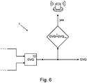
- a limit value for the gas portion of the medium flowing through the measuring tube it is possible to react to a limit value for the gas portion of the medium flowing through the measuring tube. In one embodiment, this is accomplished by comparing the calculated dimension GVQ for the gas portion of the medium flowing through the measuring tube with a limit value GVQ limit for the gas portion of the medium flowing through the measuring tube and with a certain deviation of the calculated dimension GVQ from the limit value GVQ limit a status message is issued. This deviation can be zero or different from zero.
- the status message can only consist of setting a bit in a register of the control and evaluation unit or writing to a memory cell with a corresponding value, the status message can be output in the form of a bus message via a bus interface, the status message can also be displayed Coriolis mass flow meter; there are many other ways of outputting the status signal.
- a hysteresis is realized in that the specific deviation of the calculated dimension GVQ from the limit value GVQ limit is chosen to be non-zero, for example GVQ tolerance . If the total value from the GVQiimit limit plus the GVQ tolerance value is exceeded, a status message is output. Conversely, the status message is deleted when the difference between the limit value GVQ limit and the tolerance value GVQ tolerance is undershot.
- the task derived at the outset is achieved in the Coriolis mass flow measuring device in question in that the method steps described above are carried out while the Coriolis mass flow measuring device is in operation. Most of the steps are carried out by the control and evaluation unit.
- the control and evaluation unit is designed in such a way that it determines the density value ⁇ 100 of the gasless medium in a ⁇ 100 step during operation of the Coriolis mass flow meter, in a ⁇ mess step the density value ⁇ mess of the measuring tube flowing medium in one GVQ step with the density value ⁇ 100 and calculates the density value ⁇ measured GVQ a measure for the gas portion of the flowing medium through the measuring tube and the degree GVQ outputs for the gas portion of the flowing medium through the measuring tube.
- a method 1 for determining the gas content in the medium 3 flowing through a Coriolis mass flow meter 2 is shown in various aspects.
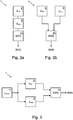
- the Coriolis mass flow meter 2 points in the illustrated embodiment Fig. 1 two curved measuring tubes 4, a vibration generator 5, two vibration sensors 6 and a control and evaluation unit 7.
- the second measuring tube is covered by the first measuring tube 4 in this view.
- the measuring tubes 4 are excited with the vibration generator 5 to produce a harmonic vibration in a basic vibration mode. If there is a flow of the medium 3 through the measuring tubes 4, opposite Coriolis forces act on the measuring tubes 4 on the inlet and outlet sides, as a result of which a superimposed higher vibration mode is generated. The phase difference between the oscillation of the measuring tubes 4 superimposed on the inlet and outlet sides is a measure of the mass flow through the measuring tubes 4.
- the control and evaluation unit 7 in the exemplary embodiment according to FIG Fig. 1 a digital signal processor and corresponding I / O interfaces for controlling the vibration exciter 5 and for reading out the vibration signals of the vibration sensors 6.
- the control measures mentioned are implemented in terms of program technology on the digital signal processor.
- a method 1 is shown with which the gas fraction in the medium 3 flowing through the Coriolis mass flow meter 2 can be determined.
- a ⁇ 100 step 8 the density value ⁇ 100 of the gasless medium is first determined.
- a ⁇ mess step 9 the density value ⁇ mess of the medium 3 flowing through the measuring tubes 4 is measured. The measurement is carried out here by determining the resonance frequency of the system.
- a measure GVQ for the gas portion of the medium 3 flowing through the measuring tubes 4 is then calculated in a GVQ step 10 with the density value ⁇ 100 and the density value ⁇ mess .
- the dimension GVQ for the gas portion of the medium 3 flowing through the measuring tubes 4 is output.
- the density value ⁇ 100 of the gasless medium is simply given as a fixed value, the density value ⁇ 100 is known in this case. This makes sense if it can practically be excluded that the density value ⁇ 100 of the gasless medium changes. In other cases, the density value ⁇ 100 of the gasless medium can also be determined, for example, by measurement, which is useful if it can be expected that the density value ⁇ 100 of the gasless medium can also change during operation.
- an indicator variable I 2-phase is used for the presence of gas inclusions in the medium flowing through the measuring tubes 4.
- the exemplary embodiments have in common that, in an indicator step 11, the indicator variable I 2-phase for the presence of gas inclusions in the medium flowing through the measuring tubes 4 3 is determined.
- this indicator variable I 2-phase is continuously determined during the operation of the Coriolis mass flow meter 2.
- the indicator size I 2-phase only provides information as to whether a gas phase is present in the medium 3 or not. It is therefore only a binary signal here.
- the indicator variable I 2-phase for the presence of gas inclusions in the medium 3 flowing through the measuring tubes 4 is determined in an indicator step 11.
- the method 1 is designed in such a way that the ⁇ 100 step 8 by measuring the density ⁇ of the medium 3 flowing through the measuring tubes 4 is only carried out if the indicator size I 2-phase indicates that the medium 3 flowing through the measuring tubes 4 is free of gas inclusions.
- the ⁇ 100 step 8 is therefore only triggered if the indicator variable I 2-phase indicates this, otherwise the ⁇ mess step 9 is calculated to determine the density value ⁇ mess when gas inclusions are present.
- the last determined value ⁇ 100 of the gasless medium 3 is then always used in the GVQ step 10.
- the density value ⁇ of the medium 3 is determined in a general step 8, 9. It is obvious that this density value ⁇ is the density value ⁇ 100 of the gasless medium 3 if the indicator size I 2-phase indicates that the medium 3 has no gas component. In the event that the medium 3 has a gas fraction - and this is therefore indicated by the indicator variable I 2-phase - the density value ⁇ corresponds to the density value ⁇ mess of the medium 3 flowing through the measuring tube 4. In the combined step 8, 9 So generally the density ⁇ of the medium 3 is always measured and, depending on the indicator size I 2-phase, saved as a density value ⁇ 100 or as a density value ⁇ mess .
- the further development of the method 1 for determining the gas content in the medium 3 flowing through the Coriolis mass flow meter 2 is characterized in that the medium pressure p m of the medium flowing through the measuring tubes 4 is measured 12 and with the measured medium pressure p m and the measured density value ⁇ meas of the medium 3 flowing through the measuring tube 4, a corrected density value ⁇ mess (p m ) is determined, the corrected density value ⁇ mess (p m ) being used as a basis for the further method as the measured density value ⁇ mess , in particular in the GVQ step 10 to determine the gas content.
- Fig. 6 shown that the calculated measure GVQ for the gas portion of the medium 3 flowing through the measuring tubes 4 is compared with a limit value GVQ limit for the gas portion of the medium 3 flowing through the measuring tube 4 and, in the case of a certain deviation of the calculated dimension GVQ from the limit value GVQ limit one Status message is issued.
- Fig. 1 is shown schematically that the control and evaluation unit 7 is connected to a display unit 13.
- the measure GVQ for the gas portion in the medium 3 can be shown here directly on the display unit 13.
- the dimension GVQ is simply output in the control and evaluation unit 7 and stored there. The value for the GVQ measure can then also be used internally, for example for control or diagnostic purposes.
Abstract
Dargestellt und beschrieben ist ein Verfahren (1) zum Ermitteln des Gasanteils in dem ein Coriolis-Massedurchflussmessgerät (2) durchströmenden Medium (3), wobei das Coriolis-Massedurchflussmessgerät (2) mindestens ein Messrohr (4), mindestens einen Schwingungserzeuger (5), mindestens zwei Schwingungsaufnehmer (6) und mindestens eine Ansteuerungs- und Auswerteeinheit (7) aufweist, wobei sich das Verfahren dadurch auszeichnet, dass in einem ρ100-Schritt (8) der Dichtewert ρ100 des gaslosen Mediums ermittelt wird, dass in einem ρmess-Schritt (9) der Dichtewert ρmess des durch das Messrohr (4) strömenden Mediums (3) gemessen wird, dass in einem GVQ-Schritt (10) mit dem Dichtewert ρ100 und dem Dichtewert ρmess ein Maß GVQ für den Gasanteil des durch das Messrohr (4) strömenden Mediums (3) berechnet wird und dass das Maß GVQ für den Gasanteil des durch das Messrohr (4) strömenden Mediums (3) ausgegeben wird.


Description
Die Erfindung betrifft ein Verfahren zum Ermitteln des Gasanteils in dem ein Coriolis-Massedurchflussmessgerät durchströmenden Medium, wobei das Coriolis-Massedurchflussmessgerät mindestens ein Messrohr, mindestens einen Schwingungserzeuger, mindestens zwei Schwingungsaufnehmer und mindestens eine Ansteuerungs- und Auswerteeinheit aufweist. Darüber hinaus betrifft die Erfindung auch ein diesbezügliches Coriolis-Massedurchflussmessgerät, das im Betrieb ein derartiges Verfahren durchführt.The invention relates to a method for determining the gas content in the medium flowing through a Coriolis mass flow meter, the Coriolis mass flow meter having at least one measuring tube, at least one vibration generator, at least two vibration sensors and at least one control and evaluation unit. In addition, the invention also relates to a Coriolis mass flow meter in this regard, which carries out such a method during operation.
Coriolis-Massedurchflussmessgeräte und Verfahren zum Betreiben von Coriolis-Massedurchflussmessgeräten sind seit vielen Jahrzehnten in ganz unterschiedlicher Ausgestaltung bekannt. Mit Coriolis-Massedurchflussmessgeräten lassen sich hohe Messgenauigkeiten erzielen, die teilweise besser sind als 0,1% vom Messwert, sodass Coriolis-Massedurchflussmessgeräte beispielsweise auch im eichpflichtigen Verkehr eingesetzt werden.Coriolis mass flow meters and methods for operating Coriolis mass flow meters have been known in many different configurations for many decades. Coriolis mass flow meters can achieve high measuring accuracies, some of which are better than 0.1% of the measured value, so that Coriolis mass flow meters are also used in custody transfer, for example.
Coriolis-Massedurchflussmessgeräte gehören zur Klasse der Vibrations-Messgeräte. Ihre Funktionsweise beruht darauf, dass wenigstens ein von einem Medium durchströmtes Messrohr von einem Schwingungserzeuger zu einer Schwingung angeregt wird. Dieser Schwingungserzeuger ist häufig ein elektrischer Antrieb, der üblicherweise als elektromagnetischer Antrieb vorliegt. Bei einem solchen elektromagnetischen Antrieb wird eine Spule von einem elektrischen Strom als elektrisches Anregungssignal durchflossen, wobei mit dem Spulenstrom in Verbindung mit der Spule unmittelbar eine Kraftwirkung auf das Messrohr ausübbar ist. Die Funktionsweise von Coriolis-Massedurchflussmessgeräten beruht darauf, dass das massebehaftete Medium aufgrund der durch zwei orthogonale Bewegungen - die der Strömung und die des Messrohres - hervorgerufene Coriolis-Trägheitskraft auf die Wandung des Messrohrs rückwirkt. Diese Rückwirkung des Mediums auf das Messrohr führt zu einer Änderung der Messrohrgeschwindigkeit im Vergleich zum undurchströmten Schwingungszustand des Messrohres. Durch die Erfassung dieser Besonderheiten der Schwingungen des durchströmten Coriolis-Messrohrs (Phasenverschiebung zwischen ein- und auslaufseitiger Messrohrschwingung) kann der Massedurchfluss durch das Messrohr mit hoher Genauigkeit bestimmt werden.Coriolis mass flow meters belong to the class of vibration meters. Their mode of operation is based on the fact that at least one measuring tube through which a medium flows is excited to oscillate by an oscillation generator. This vibration generator is often an electric drive, which is usually present as an electromagnetic drive. In such an electromagnetic drive, a coil is flowed through by an electric current as an electrical excitation signal, with the coil current in conjunction with the coil being able to directly exert a force on the measuring tube. The functionality of Coriolis mass flow meters is based on the fact that the mass-laden medium reacts on the wall of the measuring tube due to the Coriolis inertial force caused by two orthogonal movements - that of the flow and that of the measuring tube. This reaction of the medium on the measuring tube leads to a change in the measuring tube speed in comparison to the non-flowed vibration state of the measuring tube. By recording these peculiarities of the vibrations of the flow through the Coriolis measuring tube (phase shift between the measuring tube vibration on the inlet and outlet side), the mass flow through the measuring tube can be determined with high accuracy.
Von besonderer Bedeutung sind die Eigenfrequenzen der schwingfähigen Teile des Coriolis-Massedurchflussmessgeräts, im Wesentlichen also die Eigenfrequenzen des durchströmten Messrohres als Schwingelement, weil die Arbeitspunkte des Coriolis-Massedurchflussmessgeräts üblicherweise auf Eigenfrequenzen des Messrohrs gelegt werden, um die erforderlichen Schwingungen für die Induktion der Coriolis-Kräfte mit einem minimalen Energieaufwand einprägen zu können. Die dann von dem Messrohr ausgeführten Schwingungen weisen eine bestimmte Form auf, die als Eigenform der jeweiligen Anregung bezeichnet wird. Ein weiterer Grund für die besondere Bedeutung von Eigenfrequenzen bei Coriolis-Massedurchflussmessgeräten ist die unmittelbare physikalische Verknüpfung zwischen der Eigenfrequenz des durchströmten Messrohrs in der jeweiligen Eigenform und der effektiv ausgelenkten Schwingmasse (Messrohrmasse und Masse des Mediums im Messrohr). Über diesen Zusammenhang kann die Dichte des Mediums in dem Messrohr bestimmt werden, was für die vorliegende Erfindung von Bedeutung ist, auch wenn es sich nicht um die primär interessierende Messgröße eines Durchflussmessgeräts handelt.Of particular importance are the natural frequencies of the oscillatable parts of the Coriolis mass flow meter, essentially the natural frequencies of the flow tube as a vibrating element, because the operating points of the Coriolis mass flow meter are usually placed on the natural frequencies of the measuring tube in order to determine the vibrations required for the induction of the Coriolis To be able to impress forces with a minimal expenditure of energy. The vibrations then carried out by the measuring tube have a certain shape, which is referred to as the intrinsic shape of the respective excitation. Another reason for the particular importance of natural frequencies in Coriolis mass flow meters is the direct physical link between the natural frequency of the flow tube in its own shape and the effectively deflected vibrating mass (measuring tube mass and mass of the medium in the measuring tube). The density of the medium in the measuring tube can be determined via this relationship, which is important for the present invention, even if it is not the primary parameter of interest of a flow measuring device.
Wenn sich die Masse des schwingfähigen Elements ändert, also die Masse des mit dem Medium durchströmten Messrohres, dann ändert sich auch die Resonanzfrequenz des angeregten bzw. untersuchten Schwingungsmodus;. Wird das Messrohr bei unveränderter Frequenz zur Schwingung angeregt, wird die angeregte Schwingung aufgrund des verschobenen Resonanzpunktes gedämpft. Verschiedene Verfahren zum Betreiben eines Coriolis-Massedurchflussmessgerätes beschäftigen sich damit, eine veränderliche Resonanzfrequenz zu erkennen und auch die Frequenz der Anregung in den Resonanzpunkt bei veränderlicher Resonanzfrequenz nachzuführen; hierzu wird beispielhaft verwiesen auf die
Eine besondere Herausforderung für den Betrieb eines Coriolis-Massedurchflussmessgeräts stellt das Auftreten einer Mehrphasenströmung dar, die einen gasförmigen Anteil aufweist. Hier wird häufig auch nur von einer Zweiphasenströmung gesprochen, wobei diesem Begriff dann das Verständnis zugrunde liegt, dass diese Strömung eine gasförmige Phase und eine nicht-gasförmige Phase aufweist, die ihrerseits flüssige und feste Bestandteile aufweisen kann. In diesem allgemeinen Sinne soll auch hier der Begriff "Zweiphasenströmung" verstanden werden.A particular challenge for the operation of a Coriolis mass flow meter is the occurrence of a multi-phase flow that has a gaseous fraction. This is often only referred to as a two-phase flow, this term then being based on the understanding that this flow has a gaseous phase and a non-gaseous phase, which in turn can have liquid and solid components. In this general sense, the term “two-phase flow” should also be understood here.
Das Auftreten einer Zweiphasenströmung (also Übergang von einer einphasigen Strömung mit nur flüssigem oder flüssig-festem Bestandteil zu einer Strömung mit Gasphase) ist deshalb problematisch, weil Gaseinschlüsse die Messgenauigkeit stark beeinflussen können und auch den sicheren Betrieb eines Coriolis-Massedurchflussmessgeräts erschweren oder sogar unmöglich machen. Die gleichen Probleme ergeben sich auch bei variierendem Gasanteil in dem strömenden Medium. Dabei können Gaseinschlüsse im Medium durchaus gewollt sein, beispielsweise bei Anwendungen in der Lebensmittelindustrie, in der verarbeitete Medien beispielsweise eine luftig aufgeschlagene Konsistenz haben können.The occurrence of a two-phase flow (i.e. transition from a single-phase flow with only a liquid or liquid-solid component to a flow with a gas phase) is problematic because gas inclusions can strongly influence the measurement accuracy and also make the safe operation of a Coriolis mass flow meter difficult or even impossible . The same problems arise with varying gas content in the flowing medium. Gas inclusions in the medium may well be wanted, for example in applications in the food industry in which processed media can have an airy consistency, for example.
Unabhängig davon, ob Medien beabsichtigt oder unbeabsichtigt Gaseinschlüsse aufweisen, leidet die Messgenauigkeit unter dem Umstand, dass nicht mehr die gesamte Masse des strömenden Mediums durch das vibrierende Messrohr in vollem Umfang ausgelenkt wird, sondern teilweise nur noch einen Teil der Auslenkung erfährt. Dies kann zum Beispiel daran liegen, dass weniger dichte Anteile im Medium dichtere Anteile umströmen, was auch für Bewegungskomponenten orthogonal zur Strömungsrichtung gilt, die für die Coriolis-Messung essenziell sind. Von Bedeutung kann auch die Kompression bzw. Dekompression gasförmiger Anteile im Medium sein, die durch die Massenträgheit schwererer flüssiger oder fester Mediumanteile bewirkt werden. Je nach Ausprägung der Gaseinschlüsse und der Form der Strömungsregime (geschichtet, wellenförmig, blasenförmig, tröpfchenförmig) können Gaseinschlüsse auch zum Aussetzen des Messbetriebes führen, weil eine durchgängige Messung nicht mehr gewährleistet werden kann.Regardless of whether media intentionally or unintentionally contain gas, the measuring accuracy suffers from the fact that the vibrating measuring tube no longer deflects the entire mass of the flowing medium to the full extent, but only partially experiences the deflection. This can be due, for example, to the fact that less dense parts flow around denser parts in the medium, which also applies to movement components orthogonal to the flow direction, which are essential for the Coriolis measurement. Compression or decompression of gaseous components in the medium, which are brought about by the inertia of heavier liquid or solid medium components, can also be important. Depending on the characteristics of the gas inclusions and the shape of the flow regime (stratified, wave-shaped, bubble-shaped, droplet-shaped), gas inclusions can also lead to the interruption of the measuring operation because a continuous measurement can no longer be guaranteed.
In der Vergangenheit sind große Anstrengungen darauf gerichtet worden, Zweiphasenströmungen zu erkennen und durch geeignete regelungstechnische Maßnahmen auf erkannte Zweiphasenströmungen zu reagieren, sodass der Messbetrieb gleichwohl fortgesetzt werden kann. Exemplarisch werden hier genannt die
Die
Vor dem aufgezeigten Hintergrund besteht ein Interesse daran, während des Messbetriebs nicht nur eine Aussage darüber zu enthalten, ob möglicherweise eine Zweiphasenströmung vorliegt, sondern vielmehr auch eine quantitative Angabe über den Gaseinteil in dem Medium zu erhalten, das durch das Messrohr eines Coriolis-Massedurchflussmessgeräts strömt.Against the background shown, there is an interest in not only containing a statement during the measuring operation as to whether there may be a two-phase flow, but rather also obtaining a quantitative indication of the amount of gas in the medium flowing through the measuring tube of a Coriolis mass flow meter .
Die zuvor hergeleitete Aufgabe wird durch verschiedene Verfahrensschritte gelöst, die üblicherweise in der Ansteuerungs- und Auswerteeinheit des Coriolis-Massedurchflussmessgeräts implementiert sind. Die Ansteuerungs- und Auswerteeinheit ist mit den Organen des Coriolis-Massedurchflussmessgerätes funktional verbunden, sodass der Schwingungserzeuger angesteuert werden kann und die von den Schwingungsaufnehmern bereitgestellten Signale aufgenommen werden können. Dabei wird es sich bei der Ansteuerungs- und Auswerteeinheit typischerweise um ein digitales Abtastsystem handeln, das beispielsweise auf dem Einsatz von digitalen Signalprozessoren basiert. Dazu gehören selbstverständlich auch vermittelnde Schaltungen zur Signalverarbeitung, wie beispielsweise Analog/Digital-Wandler, Digital/Analog-Wandler und möglicherweise elektronische Leistungskomponenten, worauf es im Rahmen der vorliegenden Erfindung im Detail jedoch nicht ankommt.The previously derived task is solved by various method steps, which are usually implemented in the control and evaluation unit of the Coriolis mass flow meter. The control and evaluation unit is functionally connected to the organs of the Coriolis mass flow meter, so that the vibration generator can be controlled and the signals provided by the vibration sensors can be recorded. The control and evaluation unit will typically be a digital scanning system based, for example, on the use of digital signal processors. Of course, this also includes mediating circuits for signal processing, such as, for example, analog / digital converters, digital / analog converters and possibly electronic power components, which, however, is not important in the context of the present invention.
Von Bedeutung ist, dass zunächst der Dichtewert ρ100 des gaslosen Mediums ermittelt wird (ρ100-Schritt). Die Kenntnis der Dichte des durch das Messrohr strömenden Mediums, wenn es keine Gasbestandteile enthält, ist von grundlegender Bedeutung für die Berechnung des Gasanteils in dem Medium, sofern es Gasanteile beinhaltet. Der Dichtewert ρ100 des gaslosen Mediums kann dabei vorgegeben und in der Ansteuerungs- und Auswerteeinheit abgelegt sein, er kann theoretisch ermittelt worden sein und er kann schließlich auf einer Messung beruhen.It is important that the density value ρ 100 of the gasless medium is first determined (ρ 100 step). Knowing the density of the medium flowing through the measuring tube, if it does not contain any gas components, is of fundamental importance for the calculation of the gas content in the medium if it contains gas components. The density value ρ 100 of the gasless medium can be predefined and stored in the control and evaluation unit, it can be determined theoretically and it can ultimately be based on a measurement.
In einem weiteren Schritt wird der Dichtewert ρmess des durch das Messrohr strömenden Mediums gemessen (ρmess-Schritt), beispielsweise indem die Resonanzfrequenz des Systems aus Messrohr und durchströmendem Medium ermittelt wird.In a further step, the density value ρ of the measuring measured by the measuring tube flowing medium (ρ measured; step), for example by the resonant frequency of the system is determined from the measuring tube and through-flowing medium.
In einem weiteren Verfahrensschritt wird mit dem Dichtewert ρ100 des gaslosen Mediums und dem Dichtewert ρmess des aktuell durch das Messrohr strömenden Mediums ein Maß GVQ für den Gasanteil des durch das Messrohr strömenden Mediums berechnet (GVQ-Schritt), sodass also eine aussagekräftige Größe über den Gasanteil in dem Medium vorliegt. Diese Größe stellt eine quantitative Aussage über den Gasanteil im Medium dar, sie ist weit mehr als eine reine Indikatorgröße über das Vorhandensein bzw. NichtVorhandensein von Gas in dem das Messrohr durchströmenden Medium.In a further method step, with the density value ρ 100 of the gas-free medium, and the density value ρ measuring the current flowing through the measuring tube medium a measure GVQ for the gas portion of the flowing through the measuring tube medium calculated (GVQ step), so that so a meaningful size over the proportion of gas in the medium is present. This quantity represents a quantitative statement about the gas content in the medium, it is far more than a mere indicator quantity about the presence or absence of gas in the medium flowing through the measuring tube.
Schließlich wird das Maß GVQ für den Gasanteil des durch das Messrohr strömenden Mediums ausgegeben, sodass der GVQ-Wert für weitere - auch messgerätinterne - Berechnungen herangezogen werden kann oder beispielsweise über eine Anzeige ausgegeben wird oder über einen Kommunikations-Anschluss (Feldbus) nach extern ausgegeben wird und so der Prozess-Überwachung dienen kann; dies ist eine beispielhafte, nicht abschließende Aufzählung.Finally, the GVQ measure for the gas portion of the medium flowing through the measuring tube is output, so that the GVQ value can be used for further calculations - also internal to the measuring device - or, for example, output via a display or externally via a communication connection (fieldbus) will and can serve as process monitoring; this is an exemplary, non-exhaustive list.
Gemäß einer Weiterbildung des erfindungsgemäßen Verfahrens ist vorgesehen, dass in einem Indikatorschritt eine Indikatorgröße I2-phase für das Vorliegen von Gaseinschlüssen in dem das Messrohr durchströmenden Medium bestimmt wird. Eine derartige Indikatorgröße zeigt lediglich an, ob eine Zweiphasenströmung vorliegt oder auch nicht. Vorzugsweise wird die Indikatorgröße I2-phase im Betrieb des Coriolis-Massedurchflussmessgerätes fortwährend bestimmt. Das Coriolis-Massedurchflussmessgerät verfügt damit immer über Kenntnis über den Zustand des das Messrohr durchströmenden Mediums hinsichtlich des Vorliegens einer gasförmigen Phase.According to a development of the method according to the invention, it is provided that an indicator variable I 2-phase for the presence of gas inclusions in the medium flowing through the measuring tube is determined in one indicator step. Such an indicator size only indicates whether there is a two-phase flow or not. The indicator variable I 2-phase is preferably determined continuously during operation of the Coriolis mass flow meter. The Coriolis mass flow meter thus always has knowledge of the state of the medium flowing through the measuring tube with regard to the presence of a gaseous phase.
Die vorbeschriebene Maßnahme ermöglicht es nun bei einer Weiterbildung des Verfahrens, den ρ100-Schritt durch Messung der Dichte des durch das Messrohr strömenden Mediums dann auszuführen, wenn die Indikatorgröße I2-phase indiziert, dass das das Messrohr durchströmende Medium frei von Gaseinschlüssen ist. Das so weitergebildete Verfahren nutzt also die Gelegenheit , beim Vorliegen einer gasfreien Mediumströmung die Dichte des gaslosen Mediums aktuell zu bestimmen. Dadurch kann auch auf eine variierende Dichte des gaslosen Mediums reagiert werden. Vorzugsweise ist vorgesehen, dass der zuletzt ermittelte Dichtewert ρ100 des gaslosen Mediums in dem GVQ-Schritt verwendet wird, sodass für eine Berechnung des Gasanteils immer der aktuellste Dichtewert des gaslosen Mediums verwendet wird.In a further development of the method, the measure described above now enables the ρ 100 step to be carried out by measuring the density of the medium flowing through the measuring tube when the indicator size I 2-phase indicates that the medium flowing through the measuring tube is free of gas inclusions. The method developed in this way thus uses the opportunity to currently determine the density of the gasless medium in the presence of a gas-free medium flow. This allows a reaction to a varying density of the gasless medium. It is preferably provided that the last determined density value ρ 100 of the gasless medium is used in the GVQ step, so that the most current density value of the gasless medium is always used for a calculation of the gas fraction.
In einer weiteren Ausgestaltung des Verfahrens löst die Indikatorgröße I2-phase den ρmess-Schritt aus, und zwar genau dann, wenn die Indikatorgröße I2-phase indiziert, dass das das Messrohr durchströmende Medium Gaseinschlüsse aufweist. In diesem Fall ist klar, dass die Dichtebestimmung nicht zu einem neuen Dichtewert ρ100 des gaslosen Mediums führt, sondern vielmehr zu einem Dichtewert ρmess des gasbehafteten Mediums, auf dessen Grundlage dann ein neuer Wert für das Maß GVQ für den Gasanteil des durch das Messrohr strömenden Mediums berechnet werden kann.In a further embodiment of the method, the indicator size I 2-phase triggers the ρ measuring step, and precisely when the indicator size I 2-phase indicates that the medium flowing through the measuring tube has gas inclusions. In this case, it is clear that the density determination does not lead to a new density value ρ 100 of the gasless medium, but rather to a density value ρ mess of the gas-laden medium, on the basis of which a new value for the measure GVQ for the gas fraction through the measuring tube flowing medium can be calculated.
In einer Ausgestaltung des Verfahrens wird als Maß GVQ für den Gasanteil des durch das Messrohr strömenden Mediums das Gas-Volumen-Verhältnis GVR berechnet (gas volume ratio oder void ratio), das dem Quotienten aus dem Gasvolumen und dem Volumen des nicht-gasförmigen Mediumanteils entspricht und sich demnach berechnet aus dem Quotienten aus der Differenz von ρ100 und ρmess und ρmess ((ρ100 - ρmess)/ρmess). In einer anderen Ausgestaltung des Verfahrens wird als Maß GVQ für den Gasannteil des durch das Messrohr strömenden Medium der Gas-Volumen-Anteil GVF berechnet (gas volume fraction oder void fraction), bei dem der Anteil des Gasvolumens auf das untersuchte Gesamtvolumen bezogen wird und sich demzufolge berechnet aus dem Quotienten aus der Differenz zwischen der Dichte ρ100 und der Dichte ρmess und der Dichte ρ100 ((ρ100 - ρmess)/ρ100).In one embodiment of the method, the GVQ is calculated as the measure GVQ for the gas portion of the medium flowing through the measuring tube (gas volume ratio or void ratio), which corresponds to the quotient of the gas volume and the volume of the non-gaseous medium portion and is therefore calculated from the quotient of the difference between ρ 100 and ρ mess and ρ mess ((ρ 100 - ρ mess ) / ρ mess ). In another embodiment of the method, the gas volume fraction GVF (gas volume fraction or void fraction) is calculated as the dimension GVQ for the gas fraction of the medium flowing through the measuring tube, in which the fraction of the gas volume is related to the total volume examined and therefore calculated from the quotient of the difference between the density ρ 100 and the density ρ mess and the density ρ 100 ((ρ 100 - ρ mess ) / ρ 100 ).
Eine bevorzugte Ausgestaltung des Verfahrens sieht vor, dass in dem GVQ-Schritt das Maß GVQ für den Gasanteil des durch das Messrohr strömenden Mediums unter der Annahme berechnet wird, dass die Dichte des Gasanteils vernachlässigbar ist, insbesondere null ist. Die oben angegebenen Berechnungen für das Gas-Volumen-Verhältnis und den Gas-Volumen-Anteil beruhen auf dieser Annahme.A preferred embodiment of the method provides that in the GVQ step the measure GVQ for the gas portion of the medium flowing through the measuring tube is calculated on the assumption that the density of the gas portion is negligible, in particular zero. The above calculations for the gas-volume ratio and the gas-volume fraction are based on this assumption.
In einer davon abweichenden Weiterentwicklung des Verfahrens ist vorgesehen, dass der Mediumdruck pm des durch das Messrohr strömenden Mediums gemessen wird und mit dem gemessenen Mediumdruck pm und dem gemessenen Dichtewert ρmess des durch das Messrohr strömenden Mediums ein korrigierter Dichtewert ρmess(pm) ermittelt wird, wobei der korrigierte Dichtewert ρmess(pm) dem weiteren Verfahren dann als gemessener Dichtewert ρmess zugrunde gelegt wird. Der Zusammenhang ρmess(pm) kann dabei experimentell ermittelt werden, er kann aber auch aufgrund von theoretischen Überlegungen hergeleitet werden. Der Zusammenhang kann in Form einer Wertetabelle abgelegt sein oder aber auch durch einen mathematischen Zusammenhang abgebildet werden. Auf die Art der Hinterlegung des Zusammenhangs ρmess(pm) kommt es im Detail nicht an, wichtig ist, dass bei dieser Ausgestaltung der Zusammenhang überhaupt berücksichtigt wird.In a further development of the method that deviates from this, it is provided that the medium pressure p m of the medium flowing through the measuring tube is measured and with the measured medium pressure p m and the measured density value ρ mess of the medium flowing through the measuring tube a corrected density value ρ mess (p m ) is determined, the corrected density value ρ mess (p m ) then being used as the measured density value ρ mess in the further method. The relationship ρ mess (p m ) can be determined experimentally, but it can also be derived on the basis of theoretical considerations. The relationship can take the form of a table of values be filed or also represented by a mathematical connection. The type of depositing the relationship ρ mess (p m ) is not important in detail, it is important that the relationship is taken into account in this configuration.
Bei einer weiteren Ausgestaltung des Verfahrens ist es möglich, auf einen Grenzwert für den Gasanteil des durch das Messrohr strömenden Mediums zu reagieren. Dies wird bei einer Ausgestaltung dadurch bewerkstelligt, dass das berechnete Maß GVQ für den Gasanteil des durch das Messrohr strömenden Mediums mit einem Grenzwert GVQlimit für den Gasanteil des durch das Messrohr strömenden Mediums verglichen wird und bei einer bestimmten Abweichung des berechneten Maßes GVQ vom Grenzwert GVQlimit eine Statusmeldung ausgegeben wird. Diese Abweichung kann null sein oder auch von null verschieden sein. Die Statusmeldung kann lediglich darin bestehen, dass in einem Register der Ansteuerungs- und Auswerteeinheit ein Bit gesetzt wird oder eine Speicherzelle mit einem entsprechenden Wert beschrieben wird, die Statusmeldung kann in Form einer Busnachricht über eine Busschnittstelle ausgegeben werden, die Statusmeldung kann auch über eine Anzeige des Coriolis-Massedurchflussmessgeräts angezeigt werden; es sind hier viele weitere Möglichkeiten der Ausgabe des Statussignals denkbar. Bei einer Ausgestaltung des vorgenannten Verfahrens wird eine Hysterese dadurch realisiert, dass die bestimmte Abweichung des berechneten Maßes GVQ vom Grenzwert GVQlimit ungleich null gewählt wird, beispielsweise also GVQtoleranz. Bei Überschreiten des Summenwertes aus dem Grenzwert GVQiimit zuzüglich dem Toleranzwert GVQtoleranz wird eine Statusmeldung ausgegeben. Umgekehrt wird die Statusmeldung gelöscht, wenn die Differenz aus dem Grenzwert GVQlimit und dem Toleranzwert GVQtoleranz unterschritten wird.In a further embodiment of the method, it is possible to react to a limit value for the gas portion of the medium flowing through the measuring tube. In one embodiment, this is accomplished by comparing the calculated dimension GVQ for the gas portion of the medium flowing through the measuring tube with a limit value GVQ limit for the gas portion of the medium flowing through the measuring tube and with a certain deviation of the calculated dimension GVQ from the limit value GVQ limit a status message is issued. This deviation can be zero or different from zero. The status message can only consist of setting a bit in a register of the control and evaluation unit or writing to a memory cell with a corresponding value, the status message can be output in the form of a bus message via a bus interface, the status message can also be displayed Coriolis mass flow meter; there are many other ways of outputting the status signal. In one embodiment of the aforementioned method, a hysteresis is realized in that the specific deviation of the calculated dimension GVQ from the limit value GVQ limit is chosen to be non-zero, for example GVQ tolerance . If the total value from the GVQiimit limit plus the GVQ tolerance value is exceeded, a status message is output. Conversely, the status message is deleted when the difference between the limit value GVQ limit and the tolerance value GVQ tolerance is undershot.
Die eingangs hergeleitete Aufgabe wird bei dem hier in Rede stehenden Coriolis-Massedurchflussmessgerät dadurch gelöst, dass die zuvor beschriebenen Verfahrensschritte im Betrieb des Coriolis-Massedurchflussmessgeräts ausgeführt werden. Ein Großteil der Schritte wird dabei von der Ansteuerungs- und Auswerteeinheit ausgeführt. Konkret bedeutet das also, dass die Ansteuerungs- und Auswerteeinheit so ausgestaltet ist, dass sie im Betrieb des Coriolis-Massedurchflussmessgeräts in einem ρ100-Schritt den Dichtewert ρ100 des gaslosen Mediums ermittelt, in einem ρmess-Schritt den Dichtewert ρmess des durch das Messrohr strömenden Mediums misst, in einem GVQ-Schritt mit dem Dichtewert ρ100 und dem Dichtewert ρmess ein Maß GVQ für den Gasanteil des durch das Messrohr strömenden Mediums berechnet und das Maß GVQ für den Gasanteil des durch das Messrohr strömenden Mediums ausgibt.The task derived at the outset is achieved in the Coriolis mass flow measuring device in question in that the method steps described above are carried out while the Coriolis mass flow measuring device is in operation. Most of the steps are carried out by the control and evaluation unit. In concrete terms, this means that the control and evaluation unit is designed in such a way that it determines the density value ρ 100 of the gasless medium in a ρ 100 step during operation of the Coriolis mass flow meter, in a ρ mess step the density value ρ mess of the measuring tube flowing medium in one GVQ step with the density value ρ 100 and calculates the density value ρ measured GVQ a measure for the gas portion of the flowing medium through the measuring tube and the degree GVQ outputs for the gas portion of the flowing medium through the measuring tube.
Im Einzelnen gibt es nun eine Vielzahl von Möglichkeiten, das dargestellte Verfahren zum Ermitteln des Gasanteils in dem ein Coriolis-Massedurchflussmessgerät durchströmenden Medium und das entsprechende Coriolis-Massedurchflussmessgerät auszugestalten und weiterzubilden. Dies wird nachfolgend anhand der Figuren beschrieben. In der Zeichnung zeigen
- Fig. 1
- schematisch ein Coriolis-Massedurchflussmessgerät, in dem ein Verfahren zum Ermitteln des Gasanteils in dem seine Messrohre durchströmenden Medium implementiert ist,
- Fig. 2
- schematisch ein Verfahren zum Ermitteln des Gasanteils in dem die Messrohre des Coriolis-Massedurchflussmessgeräts durchfließenden Mediums,
- Fig. 2
- schematisch eine weitere Ausgestaltung des Verfahrens zum Ermitteln des Gasanteils in dem ein Coriolis-Massedurchflussmessgerät durchströmenden Medium,
- Fig. 3
- schematisch das Verfahren zum Ermitteln des Gasanteils unter Nutzung einer Indikatorgröße für eine Zweiphasenströmung,
- Fig. 4
- eine weitere Variante des Verfahrens zum Ermitteln des Gasanteils unter Verwendung einer Indikatorgröße für eine Zweiphasenströmung,
- Fig. 5
- eine weitere Ausgestaltung der vorgenannten Verfahren unter Verwendung des Mediumdrucks und
- Fig. 6
- eine Ausgestaltung des Verfahrens unter Nutzung eines Grenzwertes für das Maß GVQ für den Gasanteil des durch das Messrohr strömenden Mediums.
- Fig. 1
- schematically a Coriolis mass flow measuring device, in which a method for determining the gas fraction in the medium flowing through its measuring tubes is implemented,
- Fig. 2
- schematically a method for determining the gas fraction in the medium flowing through the measuring tubes of the Coriolis mass flow meter,
- Fig. 2
- schematically a further embodiment of the method for determining the gas content in the medium flowing through a Coriolis mass flow meter,
- Fig. 3
- schematically the method for determining the gas fraction using an indicator size for a two-phase flow,
- Fig. 4
- another variant of the method for determining the gas fraction using an indicator size for a two-phase flow,
- Fig. 5
- a further embodiment of the aforementioned methods using the medium pressure and
- Fig. 6
- an embodiment of the method using a limit value for the dimension GVQ for the gas portion of the medium flowing through the measuring tube.
In den
Im Betrieb werden die Messrohre 4 mit dem Schwingungserzeuger 5 zu einer harmonischen Schwingung in einem Grundschwingungsmode angeregt. Bei Vorliegen einer Strömung des Mediums 3 durch die Messrohre 4 wirken ein- und auslaufseitig entgegengerichtete Coriolis-Kräfte auf die Messrohre 4, wodurch ein überlagerter höherer Schwingungsmode erzeugt wird. Der Phasenunterschied zwischen der ein- und auslaufseitigen überlagerten Schwingung der Messrohre 4 ist ein Maß für den Massedurchfluss durch die Messrohre 4.In operation, the measuring
Wie eingangs ausgeführt worden ist, ist das Auftreten einer Zweiphasenströmung, also einer Strömung mit einem Gasanteil und einem flüssigen und/oder festen Strömungsanteil problematisch, weil Dämpfungs- und Rauscheffekte die Messung beeinträchtigen. Veränderliche Gasanteile bewirken zudem auch eine Änderung in der Dichte des Mediums 3 und damit auch eine Änderung der Resonanzfrequenz des schwingfähigen Elements bestehend aus den Messrohren 4 und dem in den Messrohren 4 strömenden Medium 3. Durch verschiedene regelungstechnische Maßnahmen kann es gelingen, den Arbeitspunkt des Coriolis-Massedurchflussmessgeräts 2 nachzuführen, indem also die Anregungsfrequenz der Schwingungserzeuger 5 der veränderlichen Resonanzfrequenz nachgeführt wird.As mentioned at the beginning, the occurrence of a two-phase flow, that is to say a flow with a gas component and a liquid and / or solid flow component, is problematic because damping and noise effects impair the measurement. Varying gas fractions also cause a change in the density of the
Die Ansteuerungs- und Auswerteeinheit 7 umfasst in dem Ausführungsbeispiel gemäß
Im Stand der Technik ist bekannt, durch Auswertung von Zustandsgrößen des Coriolis-Massedurchflussmessgeräts 2 das Auftreten einer Zweiphasenströmung zu erkennen und mit einer entsprechenden Indikatorgröße zu signalisieren, wobei eine solche Indikatorgröße keine zuverlässige quantitative Aussage über den Gasanteil im Medium 3 beinhaltet, sondern vielmehr eine binäre Aussage darüber macht, ob das Medium 3 einen Gasanteil aufweist oder nicht.It is known in the prior art to recognize the occurrence of a two-phase flow by evaluating state variables of the Coriolis
In den
In dem Ausführungsbeispiel gemäß
In den
Bei dem Ausführungsbeispiel gemäß
Die in
Schließlich ist in
In
- 11
- Verfahrenmethod
- 22nd
- Coriolis-MassedurchflussmessgerätCoriolis mass flow meter
- 33rd
- Mediummedium
- 44th
- MessrohreMeasuring tubes
- 55
- SchwingungserzeugerVibrator
- 66
- SchwingungsaufnehmerVibration sensor
- 77
- Ansteuerungs- und AuswerteeinheitControl and evaluation unit
- 88th
- ρ100-Schrittρ 100 step
- 99
- ρmess-Schrittρ mess step
- 1010th
- GVQ-SchrittGVQ step
- 1111
- IndikatorschrittIndicator step
- 1212th
- Messen des Mediumdrucks pm Measuring the medium pressure p m
- 1313
- AnzeigeeinheitDisplay unit
- 1414
- FeldbusschnittstelleFieldbus interface
- 1515
- Ermitteln eines korrigierten Dichtewertes ρmess(pm)Determination of a corrected density value ρ mess (p m )
Claims (10)
dadurch gekennzeichnet,
dass in einem ρ100-Schritt (8) der Dichtewert ρ100 des gaslosen Mediums ermittelt wird,
dass in einem ρmess-Schritt (9) der Dichtewert ρmess des durch das Messrohr (4) strömenden Mediums (3) gemessen wird,
dass in einem GVQ-Schritt (10) mit dem Dichtewert ρ100 und dem Dichtewert ρmess ein Maß GVQ für den Gasanteil des durch das Messrohr (4) strömenden Mediums (3) berechnet wird und
dass das Maß GVQ für den Gasanteil des durch das Messrohr (4) strömenden Mediums (3) ausgegeben wird.Method (1) for determining the gas content in the medium (3) flowing through a Coriolis mass flow meter (2), the Coriolis mass flow meter (2) having at least one measuring tube (4), at least one vibration generator (5), at least two vibration sensors (6 ) and has at least one control and evaluation unit (7),
characterized,
that the density value ρ 100 of the gasless medium is determined in a ρ 100 step (8),
that is measured in a measuring ρ -Step (9) of the density value ρ of the measuring by the measuring tube (4) flowing medium (3),
that in a GVQ step (10) with the density value ρ 100 and the density value ρ mess, a measure GVQ for the gas portion of the medium (3) flowing through the measuring tube (4) is calculated and
that the dimension GVQ for the gas portion of the medium (3) flowing through the measuring tube (4) is output.
dadurch gekennzeichnet,
dass die Ansteuerungs- und Auswerteeinheit (7) so ausgestaltet ist, dass sie im Betrieb des Coriolis-Massedurchflussmessgeräts (2) in einem ρ100-Schritt (8) den Dichtewert ρ100 des gaslosen Mediums ermittelt,
in einem ρmess-Schritt (9) den Dichtewert ρmess des durch das Messrohr (4) strömenden Mediums (3) misst,
in einem GVQ-Schritt (10) mit dem Dichtewert ρ100 und dem Dichtewert ρmess ein Maß GVQ für den Gasanteil des durch das Messrohr (4) strömenden Mediums (3) berechnet und
das Maß GVQ für den Gasanteil des durch das Messrohr (4) strömenden Mediums (3) ausgibt.Coriolis mass flow meter (2) with at least one measuring tube (4) through which a medium (3) can flow, at least one vibration generator (5), at least two vibration sensors (6) and at least one control and evaluation unit (7),
characterized,
that the control and evaluation unit (7) is designed such that it determines the density value ρ 100 of the gasless medium in a ρ 100 step (8) when the Coriolis mass flow measuring device (2) is in operation,
measuring in a ρ measured -Step (9) the density value ρ of the measuring by the measuring tube (4) flowing medium (3),
in a GVQ step (10) with the density value ρ 100 and the density value ρ mess, a measure GVQ for the gas portion of the medium (3) flowing through the measuring tube (4) is calculated and
outputs the dimension GVQ for the gas portion of the medium (3) flowing through the measuring tube (4).
Applications Claiming Priority (1)
| Application Number | Priority Date | Filing Date | Title |
|---|---|---|---|
| DE102018123534.8A DE102018123534A1 (en) | 2018-09-25 | 2018-09-25 | Method for determining the gas content in the medium flowing through a Coriolis mass flow meter |
Publications (2)
| Publication Number | Publication Date |
|---|---|
| EP3628983A1 true EP3628983A1 (en) | 2020-04-01 |
| EP3628983B1 EP3628983B1 (en) | 2023-03-22 |
Family
ID=67981914
Family Applications (1)
| Application Number | Title | Priority Date | Filing Date |
|---|---|---|---|
| EP19197466.6A Active EP3628983B1 (en) | 2018-09-25 | 2019-09-16 | Method for determining the gas content in a medium flowing through a coriolis mass flow meter and coriolis mass flow meter |
Country Status (4)
| Country | Link |
|---|---|
| US (1) | US11009380B2 (en) |
| EP (1) | EP3628983B1 (en) |
| CN (1) | CN110940388A (en) |
| DE (1) | DE102018123534A1 (en) |
Families Citing this family (2)
| Publication number | Priority date | Publication date | Assignee | Title |
|---|---|---|---|---|
| DE102020114713A1 (en) | 2020-06-03 | 2021-12-09 | Krohne Ag | Method for determining flow measurement values of a Coriolis mass flow meter in the presence of a two-phase flow |
| CN115160468B (en) * | 2022-08-11 | 2023-08-25 | 浙江京博聚烯烃新材料有限公司 | Polymerization method for preparing polyolefin material with controllable copolymerization composition |
Citations (11)
| Publication number | Priority date | Publication date | Assignee | Title |
|---|---|---|---|---|
| US6327914B1 (en) * | 1998-09-30 | 2001-12-11 | Micro Motion, Inc. | Correction of coriolis flowmeter measurements due to multiphase flows |
| US20020033043A1 (en) * | 1999-10-28 | 2002-03-21 | Dutton Robert E. | Multiphase flow measurement system |
| US20050022611A1 (en) * | 2003-06-26 | 2005-02-03 | John Hemp | Viscosity-corrected flowmeter |
| US20050138993A1 (en) * | 2003-12-12 | 2005-06-30 | Mattar Wade M. | Densitometer with pulsing pressure |
| US20060096388A1 (en) * | 2004-11-05 | 2006-05-11 | Gysling Daniel L | System for measuring a parameter of an aerated multi-phase mixture flowing in a pipe |
| DE102005012505A1 (en) | 2005-02-16 | 2006-08-24 | Krohne Ag | Method for operating a mass flowmeter |
| DE102006017676B3 (en) | 2006-04-12 | 2007-09-27 | Krohne Meßtechnik GmbH & Co KG | Coriolis-mass flow rate measuring device operating method, involves utilizing indicator parameter and additional indicator parameter for detection of multiphase flow, where additional parameter is independent of indicator parameter |
| DE102006031198A1 (en) | 2006-07-04 | 2008-01-17 | Krohne Ag | Method of operating a Coriolis mass flowmeter |
| DE102008039012A1 (en) | 2008-08-21 | 2010-03-04 | Krohne Meßtechnik GmbH & Co KG | Method for operating a resonance measuring system and resonance measuring system |
| DE102013020603B3 (en) | 2013-12-13 | 2015-04-30 | Krohne Messtechnik Gmbh | Method of operating a Coriolis mass flowmeter |
| DE102016100952A1 (en) | 2016-01-20 | 2017-07-20 | Krohne Messtechnik Gmbh | A method of operating a Coriolis mass flowmeter and Coriolis mass flowmeter |
Family Cites Families (10)
| Publication number | Priority date | Publication date | Assignee | Title |
|---|---|---|---|---|
| US7059199B2 (en) * | 2003-02-10 | 2006-06-13 | Invensys Systems, Inc. | Multiphase Coriolis flowmeter |
| US7188534B2 (en) * | 2003-02-10 | 2007-03-13 | Invensys Systems, Inc. | Multi-phase coriolis flowmeter |
| CN100394146C (en) * | 2003-05-05 | 2008-06-11 | 因万西斯系统股份有限公司 | Two-phase steam measurement system |
| CN101663566B (en) * | 2007-05-03 | 2013-06-19 | 微动公司 | Vibratory flow meter and method for correcting for an entrained phase in a two-phase flow of a flow material |
| WO2010085980A1 (en) * | 2009-01-30 | 2010-08-05 | Siemens Aktiengesellschaft | Coriolis flowmeter and method for calculating the gas fraction in a liquid |
| BRPI1013971A2 (en) * | 2009-05-04 | 2017-09-26 | Agar Corp Ltd | methods and apparatus for multiphase fluid measurement. |
| CN102652253B (en) * | 2009-12-14 | 2014-09-17 | 西门子公司 | Method for operating a coriolis mass flow rate meter and coriolis mass flow rate meter |
| EP2609402B1 (en) * | 2010-08-24 | 2021-02-17 | Schneider Electric Systems USA, Inc. | Multiphase flow metering |
| DE102011012498A1 (en) * | 2010-11-19 | 2012-05-24 | Krohne Messtechnik Gmbh | Method for operating resonant measuring system, particularly in form of coriolis mass flow meter or in form of density measuring device, involves determining measured value for amplitude-dependent state variable of multi-phase medium |
| DE102016122241A1 (en) * | 2016-11-18 | 2018-05-24 | Krohne Messtechnik Gmbh | A method of operating a Coriolis mass flowmeter and Coriolis mass flowmeter |
-
2018
- 2018-09-25 DE DE102018123534.8A patent/DE102018123534A1/en active Pending
-
2019
- 2019-09-16 EP EP19197466.6A patent/EP3628983B1/en active Active
- 2019-09-25 US US16/582,795 patent/US11009380B2/en active Active
- 2019-09-25 CN CN201910912272.1A patent/CN110940388A/en active Pending
Patent Citations (11)
| Publication number | Priority date | Publication date | Assignee | Title |
|---|---|---|---|---|
| US6327914B1 (en) * | 1998-09-30 | 2001-12-11 | Micro Motion, Inc. | Correction of coriolis flowmeter measurements due to multiphase flows |
| US20020033043A1 (en) * | 1999-10-28 | 2002-03-21 | Dutton Robert E. | Multiphase flow measurement system |
| US20050022611A1 (en) * | 2003-06-26 | 2005-02-03 | John Hemp | Viscosity-corrected flowmeter |
| US20050138993A1 (en) * | 2003-12-12 | 2005-06-30 | Mattar Wade M. | Densitometer with pulsing pressure |
| US20060096388A1 (en) * | 2004-11-05 | 2006-05-11 | Gysling Daniel L | System for measuring a parameter of an aerated multi-phase mixture flowing in a pipe |
| DE102005012505A1 (en) | 2005-02-16 | 2006-08-24 | Krohne Ag | Method for operating a mass flowmeter |
| DE102006017676B3 (en) | 2006-04-12 | 2007-09-27 | Krohne Meßtechnik GmbH & Co KG | Coriolis-mass flow rate measuring device operating method, involves utilizing indicator parameter and additional indicator parameter for detection of multiphase flow, where additional parameter is independent of indicator parameter |
| DE102006031198A1 (en) | 2006-07-04 | 2008-01-17 | Krohne Ag | Method of operating a Coriolis mass flowmeter |
| DE102008039012A1 (en) | 2008-08-21 | 2010-03-04 | Krohne Meßtechnik GmbH & Co KG | Method for operating a resonance measuring system and resonance measuring system |
| DE102013020603B3 (en) | 2013-12-13 | 2015-04-30 | Krohne Messtechnik Gmbh | Method of operating a Coriolis mass flowmeter |
| DE102016100952A1 (en) | 2016-01-20 | 2017-07-20 | Krohne Messtechnik Gmbh | A method of operating a Coriolis mass flowmeter and Coriolis mass flowmeter |
Also Published As
| Publication number | Publication date |
|---|---|
| US11009380B2 (en) | 2021-05-18 |
| US20200096374A1 (en) | 2020-03-26 |
| EP3628983B1 (en) | 2023-03-22 |
| CN110940388A (en) | 2020-03-31 |
| DE102018123534A1 (en) | 2020-03-26 |
Similar Documents
| Publication | Publication Date | Title |
|---|---|---|
| EP1281938B1 (en) | Coriolis-type mass flowmeter/densimeter | |
| DE69928422T2 (en) | FIXING THE EFFECT OF TEMPORARY BUBBLE IN CORIOLIS FLOWMETER | |
| DE10002635C2 (en) | Method for determining at least one characteristic quantity of a mass flow meter | |
| EP3559609B1 (en) | Mass flow meter according to the coriolis principle and method for determining a mass flow | |
| EP2677284B1 (en) | Method for operating a resonance measuring system and corresponding resonance measuring system | |
| EP1845346A2 (en) | Method for operating a Coriolis mass flow measuring device | |
| DE102015221350A1 (en) | METHOD FOR DELIVERING A QUALITY MEASUREMENT FOR MEASURING DEVICE REVIEW RESULTS | |
| WO2013092104A1 (en) | Method and measurement system for determining a density of a fluid | |
| EP3045877B1 (en) | Method for operating a coriolis mass flow measuring device | |
| EP1876428A1 (en) | Method for operating a Coriolis mass flow measuring device | |
| WO2011072711A1 (en) | Method for operating a coriolis mass flow rate meter and coriolis mass flow rate meter | |
| EP3628983B1 (en) | Method for determining the gas content in a medium flowing through a coriolis mass flow meter and coriolis mass flow meter | |
| WO2019086188A2 (en) | Method for identifiying deposit formation in a measuring tube and measuring device for carrying out said method | |
| WO2019219321A1 (en) | Measuring device for determining the density, the mass flow rate and/or the viscosity of a flowable medium, and method for operating same | |
| EP3887771B1 (en) | Method for determining a flow rate of a flowable medium and measurement point therefor | |
| EP2157412A2 (en) | Method for operating a resonance measuring system and resonance measuring system | |
| EP2733472A1 (en) | Nuclear magnetic resonance flow measurement device and method for operating nuclear magnetic resonance flow measurement devices | |
| WO2019110251A1 (en) | Method for determining the viscosity of a medium by means of a coriolis mass flow meter and coriolis mass flow meter for performing the method | |
| EP4127612B1 (en) | Method for operating a coriolis measurement device | |
| DE102017127266A1 (en) | A method of signaling a standard frequency of a densitometer having at least one oscillatable measuring tube for guiding a medium | |
| DE102021120452A1 (en) | Method of operating a Coriolis meter | |
| WO2010085980A1 (en) | Coriolis flowmeter and method for calculating the gas fraction in a liquid | |
| EP3963293B1 (en) | Measuring device for characterizing a non-homogeneous, flowable medium | |
| WO2010091700A1 (en) | Method for the operation of a coriolis mass flowmeter, and coriolis mass flowmeter | |
| EP3208598A1 (en) | Method for operating a coriolis mass flow measuring device |
Legal Events
| Date | Code | Title | Description |
|---|---|---|---|
| PUAI | Public reference made under article 153(3) epc to a published international application that has entered the european phase |
Free format text: ORIGINAL CODE: 0009012 |
|
| STAA | Information on the status of an ep patent application or granted ep patent |
Free format text: STATUS: THE APPLICATION HAS BEEN PUBLISHED |
|
| AK | Designated contracting states |
Kind code of ref document: A1 Designated state(s): AL AT BE BG CH CY CZ DE DK EE ES FI FR GB GR HR HU IE IS IT LI LT LU LV MC MK MT NL NO PL PT RO RS SE SI SK SM TR |
|
| AX | Request for extension of the european patent |
Extension state: BA ME |
|
| STAA | Information on the status of an ep patent application or granted ep patent |
Free format text: STATUS: REQUEST FOR EXAMINATION WAS MADE |
|
| 17P | Request for examination filed |
Effective date: 20201001 |
|
| RBV | Designated contracting states (corrected) |
Designated state(s): AL AT BE BG CH CY CZ DE DK EE ES FI FR GB GR HR HU IE IS IT LI LT LU LV MC MK MT NL NO PL PT RO RS SE SI SK SM TR |
|
| GRAP | Despatch of communication of intention to grant a patent |
Free format text: ORIGINAL CODE: EPIDOSNIGR1 |
|
| STAA | Information on the status of an ep patent application or granted ep patent |
Free format text: STATUS: GRANT OF PATENT IS INTENDED |
|
| RIC1 | Information provided on ipc code assigned before grant |
Ipc: G01N 9/00 20060101ALN20221017BHEP Ipc: G01F 15/02 20060101ALI20221017BHEP Ipc: G01F 25/10 20220101ALI20221017BHEP Ipc: G01F 1/84 20060101ALI20221017BHEP Ipc: G01F 1/74 20060101AFI20221017BHEP |
|
| INTG | Intention to grant announced |
Effective date: 20221109 |
|
| GRAS | Grant fee paid |
Free format text: ORIGINAL CODE: EPIDOSNIGR3 |
|
| GRAA | (expected) grant |
Free format text: ORIGINAL CODE: 0009210 |
|
| STAA | Information on the status of an ep patent application or granted ep patent |
Free format text: STATUS: THE PATENT HAS BEEN GRANTED |
|
| AK | Designated contracting states |
Kind code of ref document: B1 Designated state(s): AL AT BE BG CH CY CZ DE DK EE ES FI FR GB GR HR HU IE IS IT LI LT LU LV MC MK MT NL NO PL PT RO RS SE SI SK SM TR |
|
| REG | Reference to a national code |
Ref country code: GB Ref legal event code: FG4D Free format text: NOT ENGLISH |
|
| REG | Reference to a national code |
Ref country code: CH Ref legal event code: EP |
|
| REG | Reference to a national code |
Ref country code: IE Ref legal event code: FG4D Free format text: LANGUAGE OF EP DOCUMENT: GERMAN |
|
| REG | Reference to a national code |
Ref country code: DE Ref legal event code: R096 Ref document number: 502019007263 Country of ref document: DE |
|
| REG | Reference to a national code |
Ref country code: AT Ref legal event code: REF Ref document number: 1555564 Country of ref document: AT Kind code of ref document: T Effective date: 20230415 |
|
| REG | Reference to a national code |
Ref country code: LT Ref legal event code: MG9D |
|
| P01 | Opt-out of the competence of the unified patent court (upc) registered |
Effective date: 20230607 |
|
| REG | Reference to a national code |
Ref country code: NL Ref legal event code: MP Effective date: 20230322 |
|
| PG25 | Lapsed in a contracting state [announced via postgrant information from national office to epo] |
Ref country code: RS Free format text: LAPSE BECAUSE OF FAILURE TO SUBMIT A TRANSLATION OF THE DESCRIPTION OR TO PAY THE FEE WITHIN THE PRESCRIBED TIME-LIMIT Effective date: 20230322 Ref country code: NO Free format text: LAPSE BECAUSE OF FAILURE TO SUBMIT A TRANSLATION OF THE DESCRIPTION OR TO PAY THE FEE WITHIN THE PRESCRIBED TIME-LIMIT Effective date: 20230622 Ref country code: LV Free format text: LAPSE BECAUSE OF FAILURE TO SUBMIT A TRANSLATION OF THE DESCRIPTION OR TO PAY THE FEE WITHIN THE PRESCRIBED TIME-LIMIT Effective date: 20230322 Ref country code: LT Free format text: LAPSE BECAUSE OF FAILURE TO SUBMIT A TRANSLATION OF THE DESCRIPTION OR TO PAY THE FEE WITHIN THE PRESCRIBED TIME-LIMIT Effective date: 20230322 Ref country code: HR Free format text: LAPSE BECAUSE OF FAILURE TO SUBMIT A TRANSLATION OF THE DESCRIPTION OR TO PAY THE FEE WITHIN THE PRESCRIBED TIME-LIMIT Effective date: 20230322 |
|
| PG25 | Lapsed in a contracting state [announced via postgrant information from national office to epo] |
Ref country code: SE Free format text: LAPSE BECAUSE OF FAILURE TO SUBMIT A TRANSLATION OF THE DESCRIPTION OR TO PAY THE FEE WITHIN THE PRESCRIBED TIME-LIMIT Effective date: 20230322 Ref country code: NL Free format text: LAPSE BECAUSE OF FAILURE TO SUBMIT A TRANSLATION OF THE DESCRIPTION OR TO PAY THE FEE WITHIN THE PRESCRIBED TIME-LIMIT Effective date: 20230322 Ref country code: GR Free format text: LAPSE BECAUSE OF FAILURE TO SUBMIT A TRANSLATION OF THE DESCRIPTION OR TO PAY THE FEE WITHIN THE PRESCRIBED TIME-LIMIT Effective date: 20230623 Ref country code: FI Free format text: LAPSE BECAUSE OF FAILURE TO SUBMIT A TRANSLATION OF THE DESCRIPTION OR TO PAY THE FEE WITHIN THE PRESCRIBED TIME-LIMIT Effective date: 20230322 |
|
| PG25 | Lapsed in a contracting state [announced via postgrant information from national office to epo] |
Ref country code: SM Free format text: LAPSE BECAUSE OF FAILURE TO SUBMIT A TRANSLATION OF THE DESCRIPTION OR TO PAY THE FEE WITHIN THE PRESCRIBED TIME-LIMIT Effective date: 20230322 Ref country code: RO Free format text: LAPSE BECAUSE OF FAILURE TO SUBMIT A TRANSLATION OF THE DESCRIPTION OR TO PAY THE FEE WITHIN THE PRESCRIBED TIME-LIMIT Effective date: 20230322 Ref country code: PT Free format text: LAPSE BECAUSE OF FAILURE TO SUBMIT A TRANSLATION OF THE DESCRIPTION OR TO PAY THE FEE WITHIN THE PRESCRIBED TIME-LIMIT Effective date: 20230724 Ref country code: ES Free format text: LAPSE BECAUSE OF FAILURE TO SUBMIT A TRANSLATION OF THE DESCRIPTION OR TO PAY THE FEE WITHIN THE PRESCRIBED TIME-LIMIT Effective date: 20230322 Ref country code: EE Free format text: LAPSE BECAUSE OF FAILURE TO SUBMIT A TRANSLATION OF THE DESCRIPTION OR TO PAY THE FEE WITHIN THE PRESCRIBED TIME-LIMIT Effective date: 20230322 |
|
| PGFP | Annual fee paid to national office [announced via postgrant information from national office to epo] |
Ref country code: GB Payment date: 20230920 Year of fee payment: 5 |
|
| PG25 | Lapsed in a contracting state [announced via postgrant information from national office to epo] |
Ref country code: SK Free format text: LAPSE BECAUSE OF FAILURE TO SUBMIT A TRANSLATION OF THE DESCRIPTION OR TO PAY THE FEE WITHIN THE PRESCRIBED TIME-LIMIT Effective date: 20230322 Ref country code: PL Free format text: LAPSE BECAUSE OF FAILURE TO SUBMIT A TRANSLATION OF THE DESCRIPTION OR TO PAY THE FEE WITHIN THE PRESCRIBED TIME-LIMIT Effective date: 20230322 Ref country code: IS Free format text: LAPSE BECAUSE OF FAILURE TO SUBMIT A TRANSLATION OF THE DESCRIPTION OR TO PAY THE FEE WITHIN THE PRESCRIBED TIME-LIMIT Effective date: 20230722 |
|
| PGFP | Annual fee paid to national office [announced via postgrant information from national office to epo] |
Ref country code: FR Payment date: 20230928 Year of fee payment: 5 |
|
| REG | Reference to a national code |
Ref country code: DE Ref legal event code: R097 Ref document number: 502019007263 Country of ref document: DE |
|
| PLBE | No opposition filed within time limit |
Free format text: ORIGINAL CODE: 0009261 |
|
| STAA | Information on the status of an ep patent application or granted ep patent |
Free format text: STATUS: NO OPPOSITION FILED WITHIN TIME LIMIT |
|
| PG25 | Lapsed in a contracting state [announced via postgrant information from national office to epo] |
Ref country code: SI Free format text: LAPSE BECAUSE OF FAILURE TO SUBMIT A TRANSLATION OF THE DESCRIPTION OR TO PAY THE FEE WITHIN THE PRESCRIBED TIME-LIMIT Effective date: 20230322 Ref country code: DK Free format text: LAPSE BECAUSE OF FAILURE TO SUBMIT A TRANSLATION OF THE DESCRIPTION OR TO PAY THE FEE WITHIN THE PRESCRIBED TIME-LIMIT Effective date: 20230322 Ref country code: CZ Free format text: LAPSE BECAUSE OF FAILURE TO SUBMIT A TRANSLATION OF THE DESCRIPTION OR TO PAY THE FEE WITHIN THE PRESCRIBED TIME-LIMIT Effective date: 20230322 |
|
| PGFP | Annual fee paid to national office [announced via postgrant information from national office to epo] |
Ref country code: DE Payment date: 20231121 Year of fee payment: 5 Ref country code: CH Payment date: 20231001 Year of fee payment: 5 |
|
| 26N | No opposition filed |
Effective date: 20240102 |