EP3628811A1 - Échelle escabeau à bras à profil bas - Google Patents
Échelle escabeau à bras à profil bas Download PDFInfo
- Publication number
- EP3628811A1 EP3628811A1 EP19166912.6A EP19166912A EP3628811A1 EP 3628811 A1 EP3628811 A1 EP 3628811A1 EP 19166912 A EP19166912 A EP 19166912A EP 3628811 A1 EP3628811 A1 EP 3628811A1
- Authority
- EP
- European Patent Office
- Prior art keywords
- ladder
- legs
- arm assembly
- fly arm
- bracket
- Prior art date
- Legal status (The legal status is an assumption and is not a legal conclusion. Google has not performed a legal analysis and makes no representation as to the accuracy of the status listed.)
- Withdrawn
Links
- 230000007704 transition Effects 0.000 claims abstract description 10
- 230000000717 retained effect Effects 0.000 claims description 6
- 238000000034 method Methods 0.000 claims description 5
- 238000010276 construction Methods 0.000 description 3
- -1 6063-T5 Chemical compound 0.000 description 2
- 238000004140 cleaning Methods 0.000 description 2
- 229920001155 polypropylene Polymers 0.000 description 2
- 239000004677 Nylon Substances 0.000 description 1
- 239000004743 Polypropylene Substances 0.000 description 1
- 229910000831 Steel Inorganic materials 0.000 description 1
- XAGFODPZIPBFFR-UHFFFAOYSA-N aluminium Chemical compound [Al] XAGFODPZIPBFFR-UHFFFAOYSA-N 0.000 description 1
- 229910052782 aluminium Inorganic materials 0.000 description 1
- 230000009194 climbing Effects 0.000 description 1
- 239000000463 material Substances 0.000 description 1
- 229920001778 nylon Polymers 0.000 description 1
- 239000010959 steel Substances 0.000 description 1
Images


Classifications
-
- E—FIXED CONSTRUCTIONS
- E06—DOORS, WINDOWS, SHUTTERS, OR ROLLER BLINDS IN GENERAL; LADDERS
- E06C—LADDERS
- E06C7/00—Component parts, supporting parts, or accessories
- E06C7/48—Ladder heads; Supports for heads of ladders for resting against objects
-
- E—FIXED CONSTRUCTIONS
- E06—DOORS, WINDOWS, SHUTTERS, OR ROLLER BLINDS IN GENERAL; LADDERS
- E06C—LADDERS
- E06C1/00—Ladders in general
- E06C1/02—Ladders in general with rigid longitudinal member or members
- E06C1/14—Ladders capable of standing by themselves
- E06C1/16—Ladders capable of standing by themselves with hinged struts which rest on the ground
-
- E—FIXED CONSTRUCTIONS
- E06—DOORS, WINDOWS, SHUTTERS, OR ROLLER BLINDS IN GENERAL; LADDERS
- E06C—LADDERS
- E06C7/00—Component parts, supporting parts, or accessories
- E06C7/14—Holders for pails or other equipment on or for ladders
-
- E—FIXED CONSTRUCTIONS
- E06—DOORS, WINDOWS, SHUTTERS, OR ROLLER BLINDS IN GENERAL; LADDERS
- E06C—LADDERS
- E06C7/00—Component parts, supporting parts, or accessories
- E06C7/42—Ladder feet; Supports therefor
- E06C7/423—Ladder stabilising struts
-
- E—FIXED CONSTRUCTIONS
- E06—DOORS, WINDOWS, SHUTTERS, OR ROLLER BLINDS IN GENERAL; LADDERS
- E06C—LADDERS
- E06C7/00—Component parts, supporting parts, or accessories
- E06C7/42—Ladder feet; Supports therefor
- E06C7/46—Non-skid equipment
Definitions
- the invention relates to ladders commonly referred to as step ladders or step stools, and more particularly relates to step ladders.
- Step ladders are a popular household convenience. These types of ladders have pairs of legs (at least one with steps or rungs) that open out into a stable A-frame configuration to allow a user to climb up to a higher position with the security of four ladder feet on the floor. Unlike extension ladders, such step ladders do not need to lean on, be attached to, or be hung from another surface. They are thus independently self-supporting.
- step ladder requires a great deal of floor space when deployed.
- the four feet must all contact the floor when the legs are fully spaced into the ladder's A-frame configuration - forming a wide rectangle on the floor.
- the user climbs up the steps, and when standing on the top cap of the ladder (if permitted), the user is directly above the center of this notional rectangle.
- the user To reach a surface opposite the ladder's steps, the user must contort his or her body to bend over toward the surface, possibly climbing higher on the ladder than necessary in order to get the user's body closer to the middle of the rectangle, which is ultimately closer to the surface desired.
- These work positions are at least uncomfortable, and possibly dangerous or unstable for the user.
- the user might position the ladder sideways to the surface desired, climb up the steps, and torque the user's body 90 degrees to reach toward the desired surface. While placing the user closer the surface, this position is ultimately uncomfortable for the user. It would be desirable to provide the convenience and stability of a step ladder while allowing a lower profile approach to a raised surface.
- a low-profile fly arm step ladder is provided.
- the ladder has a pair of first ladder legs with a plurality of steps mounted therebetween.
- a bracket arrangement is mounted to an upper end of each of the first ladder legs.
- a pair of second ladder legs is mounted, each in hinged relation with a portion of the bracket arrangement of a corresponding first ladder leg.
- the ladder also has a fly arm assembly with a configuration with two ends on one side, each such end being mounted with a portion of the bracket arrangement of a respective first ladder leg.
- the bracket arrangements permit:
- the fly arm assembly may be applied as an optional accessory to an existing ladder, and may be mounted in various arrangements.
- the second ladder legs are preferably in the storage position when the ladder is in the braced single ladder position. This contributes to the "low-profile". Only one set of feet is on the floor in the braced single ladder position.
- the surface is a countertop.
- the distance between the fly arm assembly and the floor in the braced single ladder position is preferably between about 80 - 100 cm.
- Each of the first ladder legs may be joined to a respective one of the second ladder legs by a spreader hinge disposed below the bracket arrangement.
- the spreader hinge circumscribes the maximum distance between the first ladder legs and the second ladder legs when extended out into the step ladder position.
- the fly arm assembly has at least one non-marring foot where the fly arm assembly contacts the surface.
- an extension portion of the first ladder legs telescopes outward from each of the first ladder legs above the bracket arrangement.
- a utility shelf is mounted on at least one of the extension portions.
- the utility shelf may be mounted on the top of the extension portions, spanning therebetween.
- the utility shelf may include leg rest surfaces on an edge such that a user can rest the user's legs on the leg rest surfaces while standing on an upper step when the extension portions are extended. Due to the telescoping, the leg rest surfaces may be adjusted to a comfortable supporting position for the individual user and task.
- the extension portions are lockable in telescoped position.
- At least one set of the first and second ladder legs have feet at their lower ends.
- the feet may be non-skid.
- the feet may be rounded for better contact with the floor over a range of deployment angles.
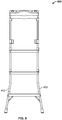
- the first ladder legs may be flared.
- the second ladder legs may also or in the alternative be flared.
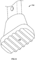
- the fly arm assembly may have a generally U-shaped configuration with each end of the U being mounted with the bracket arrangement of a corresponding first ladder leg.
- U-shaped configuration it is simply intended that the fly arm assembly has a configuration with a return.
- Such configurations need not literally be shaped like the letter “U”, but may take other forms instead.
- V-shaped, circular, oval, semicircular and other shapes may also be considered a "U-shaped configuration" for the present purposes without departing from the intended scope.
- the fly arm assembly may be mounted, for example, in hinged relation such that it can transition from a storage position abutting the first ladder legs to its extended position in the braced single ladder position.
- each bracket arrangement may comprise two brackets, one holding the respective second ladder leg, and one holding an end of the fly arm assembly.
- a single bracket may be provided with two channels, one holding the respective second ladder leg, and one holding an end of the fly arm assembly.
- the single ladder leg may be retained in an outer channel of the bracket, while the end of the fly arm assembly is retained in an inner channel of the bracket.
- a method for assembling a low-profile fly arm step ladder is provided.
- a bracket arrangement is mounted to the upper end of each of a pair of first ladder legs which have a plurality of steps mounted therebetween.
- a pair of second ladder legs is mounted in hinged relation with a respective bracket arrangement.
- a fly arm assembly with two ends on the same side is mounted to this ladder, each end of the fly arm assembly being mounted with a respective bracket arrangement.
- the bracket arrangements permit:
- a pair of brackets is also provided for use with this method.
- a fly arm assembly is also provided for use with this method.
- the low-profile fly arm step ladder 100 is a step ladder that has three basic modes:
- the ladder 100 has a pair of first ladder legs 102. Steps or rungs 106 are mounted between the first ladder legs 102.
- a pair of bracket arrangements (in this case, single brackets 108 ) is provided. An example of the single bracket is shown in Figure 5 .
- the opening 126 of extension portion 128 is slid onto the upper ends of the first legs 102 and attached thereto.
- the brackets also have a bracket body 130 with an inner channel 132B and an outer channel 132A.
- a pair of second ladder legs 104 is provided. These are mounted in hinged relation in the outer channels 132A of the brackets 108.
- a fly arm assembly 110 is also provided.
- the fly arm assembly has a generally U-shaped configuration (seen in detail in Fig. 4 ). Each end of the U is mounted in hinged relation in the inner channel 132B of a respective bracket 108. It will be appreciated that multi-bracket arrangements, non-U shaped configurations, and non-hinged arrangements are also possible.
- the second ladder legs 104 are folded to lie flat with (and abut) the first ladder legs 102.
- the fly arm assembly 110 may also be folded down to nest within the second ladder legs 104 and lie flat with the first ladder legs 102.
- the first and second ladder legs 102, 104 are moved into an A-frame configuration (using the brackets 108 as a hinge).
- the first legs have optional extension portions 102' that telescope upward from their bracketed upper ends to provide additional height.
- the telescoping extension portions may use any known construction with any type of locking mechanism.
- one type of lock 122 is the spring button type shown in Fig. 2 .
- a utility shelf 120 may be provided at an upper end of the extension portions 102'.
- a spreader hinge 118 may be provided to join the first and second ladder legs 102, 104 and circumscribe the maximum distance they may be parted in the step ladder position.
- the fly arm assembly 110 is preferably folded down to lie flat with the first ladder legs 102, as shown in Fig. 2 .
- the first and second ladder legs are folded to lie flat together.
- the fly arm assembly is folded out.
- the ladder is leaned toward a raised surface (such as counter 200 ).
- the feet 114 of the first legs 102 are on the floor 300.
- the feet 124 of the fly arm contact portions 112 of the fly arm assembly 110 rest on the raised surface 200. These contact portions 112 are the only part of the ladder that contacts the countertop 200. So, acting together with the feet 114 of the first ladder legs 102, there are four points of planar contact to stabilize the ladder (two at the floor 300 level, and two at counter height h).
- the fly arm assembly 110 simply folds out and rests (at its contact points) on the surface 200. It does not need to be attached or locked to the surface or in any way adjusted.
- the brackets 108 act as the hinge and provide the outer limits for the fly arm assembly in deployed state.
- the user just needs to position the ladder so that the deployed fly arm assembly is roughly parallel with the surface 200.
- the ladder preferably accommodates a range of standard counter heights ( h ) - e.g. about 80-100 cm.
- the angle of the ladder relative to the folded out fly arm assembly will be approximately 110-120 degrees.
- the preferred brackets 108 due to their twin channel 132A, 132B design, also allow the fly arm assembly 110 to be folded (or deployed) independently of the second legs 104.
- the legs 104 and fly arm assembly 110 do not interfere with one another.
- each of these functions may be accomplished with a separate bracket (so that multiple brackets in parallel serve as a "bracket arrangement").
- the extension portions of the first legs can also be extended so that the utility shelf 120 is at a useful height for working.
- the user can lean on the utility shelf, or use it as a staging area for objects being removed from or put into the cupboards 210 above the counter 200.
- the utility shelf 120 can also have a central recess 136 and/or various slots, openings or cavities 138, 140 for attachment of articles or tools (e.g. cleaning products for use at height). Hooks may also be provided (not shown).
- the openings 138 can also be used for hanging the ladder 100 when stored.
- the utility shelf 120 may also include leg rest indents or surfaces 142 to allow the user to rest (lean) the user's legs against the utility shelf when the extension portions are fully extended, while the user is standing on the top step.
- the ladder In the braced single ladder position, the ladder allows close-in and easy access to the counter 200 and cupboard 210 areas while lateral or forward movement of the ladder is prevented by the contact portions 112. Because only one set of ladder legs 102 is deployed (the second set 104 being effectively replaced by the fly arm assembly 110 ), the ladder does not need the wide rectangle footprint of floorspace that it would otherwise need in a step ladder configuration. It has a low-profile in this sense. The user is front facing to the intended work area and can work in a secure, ergonomic manner.
- the ladder does not lean on (or hook onto) the edge of the counter, and accordingly does not have side-to-side shift, or the potential to mar or dent the edge from weight.
- the force is distributed between the first legs 102 and the contact portions 112.
- the contact portions 112 are non-marring and anti-skid.
- the feet of the ladder 114, 116 are preferably also non-marring and anti-skid.
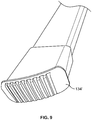
- the feet have rounded or ruggedized bottom surfaces 134 to better contact and grip the floor.
- An embodiment of the foot with a rounded bottom surface 134' is shown for example in Figure 9 .
- first ladder legs 402 may be flared, as shown in Figure 8 . This may be preferred or required for certain task or weight bearing requirements.
- the legs 102, 104, steps 106, and extension portions 102', as well as the extension bars 110A and crossbar 110B of the fly arm assembly 110, are preferably of aluminum (such as 6063-T5, 6061-T5, or 6005-T5).
- the fly arm contact portions 112 and brackets (or bracket arrangements) 108 are preferably of nylon (such asPA66, PA6 or PA610).
- the feet 114, 116, step brackets, and utility shelf 120 are preferably of Polypropylene (such as PP-R, PP-H or PP-B).
- the spreader hinges 118 are preferably of steel (such as A3). It will be appreciated that these are merely examples and not statements of essential requirements.
- the ladder is preferably built to conform to ANSI Standards for step ladders.
- the invention may be defined by any of the following numbered clauses.
Landscapes
- Engineering & Computer Science (AREA)
- Mechanical Engineering (AREA)
- Ladders (AREA)
Applications Claiming Priority (1)
| Application Number | Priority Date | Filing Date | Title |
|---|---|---|---|
| US16/142,318 US20200095828A1 (en) | 2018-09-26 | 2018-09-26 | Low-Profile Fly Arm Step Ladder |
Publications (1)
| Publication Number | Publication Date |
|---|---|
| EP3628811A1 true EP3628811A1 (fr) | 2020-04-01 |
Family
ID=66091986
Family Applications (1)
| Application Number | Title | Priority Date | Filing Date |
|---|---|---|---|
| EP19166912.6A Withdrawn EP3628811A1 (fr) | 2018-09-26 | 2019-04-02 | Échelle escabeau à bras à profil bas |
Country Status (4)
| Country | Link |
|---|---|
| US (1) | US20200095828A1 (fr) |
| EP (1) | EP3628811A1 (fr) |
| AU (1) | AU2019202253A1 (fr) |
| CA (1) | CA3039600A1 (fr) |
Families Citing this family (5)
| Publication number | Priority date | Publication date | Assignee | Title |
|---|---|---|---|---|
| CN210003203U (zh) * | 2019-01-25 | 2020-01-31 | 江苏宙际杰智能科技股份有限公司 | 用于梯子的伸缩定位结构 |
| US20220025705A1 (en) * | 2020-07-21 | 2022-01-27 | Jay Mislich | Ladder safety device |
| US11440480B2 (en) * | 2021-01-07 | 2022-09-13 | John E. Dickman | Ladder hanging bracket |
| US12065881B1 (en) * | 2023-03-20 | 2024-08-20 | Calvin Coolridge Barrett | Extension ladder weight distribution stand |
| US20240352792A1 (en) * | 2023-04-18 | 2024-10-24 | Nicolas Ramirez | Ladder and entertainment combination system |
Citations (3)
| Publication number | Priority date | Publication date | Assignee | Title |
|---|---|---|---|---|
| US3009535A (en) * | 1959-01-13 | 1961-11-21 | White Metal Rolling & Stamping | Stepladders |
| US4155422A (en) * | 1978-07-03 | 1979-05-22 | White Metal Rolling & Stamping Corp. | Combination step, stair well and extension ladders |
| WO1999009289A2 (fr) * | 1997-08-19 | 1999-02-25 | C-6 Products, Inc. | Accessoire pour escabeau |
Family Cites Families (18)
| Publication number | Priority date | Publication date | Assignee | Title |
|---|---|---|---|---|
| US2109886A (en) * | 1936-05-16 | 1938-03-01 | Michigan Ladder Company | Stepladder |
| US2423477A (en) * | 1943-12-23 | 1947-07-08 | Brimboeuf Gaston | Stepladder guard attachment |
| US2533391A (en) * | 1947-05-14 | 1950-12-12 | Carl J Miller | Combination step and wall ladder |
| US4376470A (en) * | 1980-11-06 | 1983-03-15 | Little Giant Industries, Inc. | Fiberglass ladder |
| US4643274A (en) * | 1986-07-11 | 1987-02-17 | Victor Tataseo | Ladder stand-off device with safety harness |
| US4723631A (en) * | 1986-09-17 | 1988-02-09 | Raymond Tremblay | Foldable ladder |
| FR2629861A2 (fr) * | 1986-10-16 | 1989-10-13 | Chuzeville Pierre | Dispositif permettant d'accrocher et de deplacer une echelle sur un toit, et echelle munie de ses elements |
| JPH06105022B2 (ja) * | 1989-06-28 | 1994-12-21 | ナショナル住宅産業株式会社 | 昇降用具 |
| US6158551A (en) * | 1999-02-25 | 2000-12-12 | Gray; Earl | Extension ladder shelf |
| US7383920B2 (en) * | 2002-06-27 | 2008-06-10 | Cosco Management, Inc. | Step stool with movable handrail |
| DE10303219A1 (de) * | 2003-01-22 | 2004-08-12 | Gerhard Blome-Tillmann | Anlehneinrichtung für eine Treppenleiter und Treppenleiter |
| US7931123B2 (en) * | 2004-11-17 | 2011-04-26 | Werner Co. | Stepladder folding twin-step |
| US7849967B2 (en) * | 2006-02-07 | 2010-12-14 | Cosco Management, Inc. | Foldable stepladder with step lock |
| DK2260170T3 (en) * | 2008-03-07 | 2016-03-21 | Wing Entpr Inc | Ladder |
| DE202012100438U1 (de) * | 2012-02-09 | 2013-05-10 | Hailo-Werk Rudolf Loh Gmbh & Co. Kg | Leiter, insbesondere Stehleiter mit einem Einsinkschutz |
| US10655391B1 (en) * | 2017-06-02 | 2020-05-19 | Ezra Clark | Safety device for an extension ladder |
| EP3524768B1 (fr) * | 2018-02-07 | 2021-04-28 | Hailo-Werk Rudolf Loh GmbH & Co. KG | Escabeau, en particulier escabeau à marches |
| US11187039B2 (en) * | 2018-08-09 | 2021-11-30 | Louisville Ladder Inc. | Configurable ladder system and method |
-
2018
- 2018-09-26 US US16/142,318 patent/US20200095828A1/en not_active Abandoned
-
2019
- 2019-04-02 EP EP19166912.6A patent/EP3628811A1/fr not_active Withdrawn
- 2019-04-02 AU AU2019202253A patent/AU2019202253A1/en not_active Abandoned
- 2019-04-08 CA CA3039600A patent/CA3039600A1/fr not_active Abandoned
Patent Citations (3)
| Publication number | Priority date | Publication date | Assignee | Title |
|---|---|---|---|---|
| US3009535A (en) * | 1959-01-13 | 1961-11-21 | White Metal Rolling & Stamping | Stepladders |
| US4155422A (en) * | 1978-07-03 | 1979-05-22 | White Metal Rolling & Stamping Corp. | Combination step, stair well and extension ladders |
| WO1999009289A2 (fr) * | 1997-08-19 | 1999-02-25 | C-6 Products, Inc. | Accessoire pour escabeau |
Also Published As
| Publication number | Publication date |
|---|---|
| AU2019202253A1 (en) | 2020-04-09 |
| CA3039600A1 (fr) | 2020-03-26 |
| US20200095828A1 (en) | 2020-03-26 |
Similar Documents
| Publication | Publication Date | Title |
|---|---|---|
| EP3628811A1 (fr) | Échelle escabeau à bras à profil bas | |
| US20240392627A1 (en) | Stepladder tray | |
| US11846137B2 (en) | Ladders, ladder components and related methods | |
| US5131492A (en) | Portable lightweight collapsible footstool with means for detachably mountable | |
| US20030029676A1 (en) | Utility tray for step stool | |
| US7967111B2 (en) | Stepladder | |
| US6158551A (en) | Extension ladder shelf | |
| US10738533B2 (en) | Portable ladder platform | |
| US5503245A (en) | Step ladder | |
| US11578533B2 (en) | Step ladder device allowing the user to stand and work safely and comfortably on the upper steps of a step ladder | |
| US20250277407A1 (en) | Deep ladder tray | |
| US4953661A (en) | Ladder attachment | |
| US20200115961A1 (en) | Top cap for multi-position ladder | |
| US20250163756A1 (en) | Configurable step assistant | |
| US4624430A (en) | Ladder caddy | |
| NZ556606A (en) | Collapsible combination ladder with telescopic legs one ladder section having wider steps than the other | |
| US20240151107A1 (en) | Multi-position ladder bucket | |
| US20240183220A1 (en) | Tray mechanisms for ladders, ladders incorporating same, and related methods | |
| WO2014126780A1 (fr) | Accessoire à plateau amovible pour échelle à cadre en a | |
| US12523097B2 (en) | Ladder storage devices | |
| CN116802378A (zh) | 用于梯子的顶盖和附件托盘以及包含该顶盖和附件托盘的梯子 | |
| US12234689B2 (en) | Ladder-mounted ledge for holding tools and materials | |
| US20260043258A1 (en) | Work platform with collapsible support | |
| US20250389154A1 (en) | Stepladder | |
| GB2277115A (en) | Ladder attachment |
Legal Events
| Date | Code | Title | Description |
|---|---|---|---|
| PUAI | Public reference made under article 153(3) epc to a published international application that has entered the european phase |
Free format text: ORIGINAL CODE: 0009012 |
|
| STAA | Information on the status of an ep patent application or granted ep patent |
Free format text: STATUS: THE APPLICATION HAS BEEN PUBLISHED |
|
| AK | Designated contracting states |
Kind code of ref document: A1 Designated state(s): AL AT BE BG CH CY CZ DE DK EE ES FI FR GB GR HR HU IE IS IT LI LT LU LV MC MK MT NL NO PL PT RO RS SE SI SK SM TR |
|
| AX | Request for extension of the european patent |
Extension state: BA ME |
|
| 18D | Application deemed to be withdrawn |
Effective date: 20201002 |