EP3628558A1 - Electromechanical brake booster - Google Patents
Electromechanical brake booster Download PDFInfo
- Publication number
- EP3628558A1 EP3628558A1 EP19203577.2A EP19203577A EP3628558A1 EP 3628558 A1 EP3628558 A1 EP 3628558A1 EP 19203577 A EP19203577 A EP 19203577A EP 3628558 A1 EP3628558 A1 EP 3628558A1
- Authority
- EP
- European Patent Office
- Prior art keywords
- gear
- brake booster
- transmission
- electromechanical brake
- gears
- Prior art date
- Legal status (The legal status is an assumption and is not a legal conclusion. Google has not performed a legal analysis and makes no representation as to the accuracy of the status listed.)
- Granted
Links
- 230000005540 biological transmission Effects 0.000 claims abstract description 43
- 238000006243 chemical reaction Methods 0.000 claims description 18
- 238000006073 displacement reaction Methods 0.000 description 8
- 210000003205 muscle Anatomy 0.000 description 4
- 230000007423 decrease Effects 0.000 description 2
- 238000004519 manufacturing process Methods 0.000 description 2
- 238000011144 upstream manufacturing Methods 0.000 description 2
- 229910000831 Steel Inorganic materials 0.000 description 1
- 230000008878 coupling Effects 0.000 description 1
- 238000010168 coupling process Methods 0.000 description 1
- 238000005859 coupling reaction Methods 0.000 description 1
- 230000000881 depressing effect Effects 0.000 description 1
- 238000011161 development Methods 0.000 description 1
- 230000018109 developmental process Effects 0.000 description 1
- 230000000977 initiatory effect Effects 0.000 description 1
- 230000003387 muscular Effects 0.000 description 1
- 230000002093 peripheral effect Effects 0.000 description 1
- 239000011295 pitch Substances 0.000 description 1
- 239000010959 steel Substances 0.000 description 1
Images
Classifications
-
- B—PERFORMING OPERATIONS; TRANSPORTING
- B60—VEHICLES IN GENERAL
- B60T—VEHICLE BRAKE CONTROL SYSTEMS OR PARTS THEREOF; BRAKE CONTROL SYSTEMS OR PARTS THEREOF, IN GENERAL; ARRANGEMENT OF BRAKING ELEMENTS ON VEHICLES IN GENERAL; PORTABLE DEVICES FOR PREVENTING UNWANTED MOVEMENT OF VEHICLES; VEHICLE MODIFICATIONS TO FACILITATE COOLING OF BRAKES
- B60T13/00—Transmitting braking action from initiating means to ultimate brake actuator with power assistance or drive; Brake systems incorporating such transmitting means, e.g. air-pressure brake systems
- B60T13/74—Transmitting braking action from initiating means to ultimate brake actuator with power assistance or drive; Brake systems incorporating such transmitting means, e.g. air-pressure brake systems with electrical assistance or drive
- B60T13/745—Transmitting braking action from initiating means to ultimate brake actuator with power assistance or drive; Brake systems incorporating such transmitting means, e.g. air-pressure brake systems with electrical assistance or drive acting on a hydraulic system, e.g. a master cylinder
-
- F—MECHANICAL ENGINEERING; LIGHTING; HEATING; WEAPONS; BLASTING
- F16—ENGINEERING ELEMENTS AND UNITS; GENERAL MEASURES FOR PRODUCING AND MAINTAINING EFFECTIVE FUNCTIONING OF MACHINES OR INSTALLATIONS; THERMAL INSULATION IN GENERAL
- F16H—GEARING
- F16H1/00—Toothed gearings for conveying rotary motion
- F16H1/02—Toothed gearings for conveying rotary motion without gears having orbital motion
- F16H1/20—Toothed gearings for conveying rotary motion without gears having orbital motion involving more than two intermeshing members
- F16H1/22—Toothed gearings for conveying rotary motion without gears having orbital motion involving more than two intermeshing members with a plurality of driving or driven shafts; with arrangements for dividing torque between two or more intermediate shafts
-
- F—MECHANICAL ENGINEERING; LIGHTING; HEATING; WEAPONS; BLASTING
- F16—ENGINEERING ELEMENTS AND UNITS; GENERAL MEASURES FOR PRODUCING AND MAINTAINING EFFECTIVE FUNCTIONING OF MACHINES OR INSTALLATIONS; THERMAL INSULATION IN GENERAL
- F16H—GEARING
- F16H19/00—Gearings comprising essentially only toothed gears or friction members and not capable of conveying indefinitely-continuing rotary motion
-
- F—MECHANICAL ENGINEERING; LIGHTING; HEATING; WEAPONS; BLASTING
- F16—ENGINEERING ELEMENTS AND UNITS; GENERAL MEASURES FOR PRODUCING AND MAINTAINING EFFECTIVE FUNCTIONING OF MACHINES OR INSTALLATIONS; THERMAL INSULATION IN GENERAL
- F16H—GEARING
- F16H35/00—Gearings or mechanisms with other special functional features
- F16H35/02—Gearings or mechanisms with other special functional features for conveying rotary motion with cyclically varying velocity ratio
-
- F—MECHANICAL ENGINEERING; LIGHTING; HEATING; WEAPONS; BLASTING
- F16—ENGINEERING ELEMENTS AND UNITS; GENERAL MEASURES FOR PRODUCING AND MAINTAINING EFFECTIVE FUNCTIONING OF MACHINES OR INSTALLATIONS; THERMAL INSULATION IN GENERAL
- F16H—GEARING
- F16H1/00—Toothed gearings for conveying rotary motion
- F16H1/02—Toothed gearings for conveying rotary motion without gears having orbital motion
- F16H1/04—Toothed gearings for conveying rotary motion without gears having orbital motion involving only two intermeshing members
- F16H1/12—Toothed gearings for conveying rotary motion without gears having orbital motion involving only two intermeshing members with non-parallel axes
- F16H1/16—Toothed gearings for conveying rotary motion without gears having orbital motion involving only two intermeshing members with non-parallel axes comprising worm and worm-wheel
-
- F—MECHANICAL ENGINEERING; LIGHTING; HEATING; WEAPONS; BLASTING
- F16—ENGINEERING ELEMENTS AND UNITS; GENERAL MEASURES FOR PRODUCING AND MAINTAINING EFFECTIVE FUNCTIONING OF MACHINES OR INSTALLATIONS; THERMAL INSULATION IN GENERAL
- F16H—GEARING
- F16H19/00—Gearings comprising essentially only toothed gears or friction members and not capable of conveying indefinitely-continuing rotary motion
- F16H19/02—Gearings comprising essentially only toothed gears or friction members and not capable of conveying indefinitely-continuing rotary motion for interconverting rotary or oscillating motion and reciprocating motion
- F16H19/04—Gearings comprising essentially only toothed gears or friction members and not capable of conveying indefinitely-continuing rotary motion for interconverting rotary or oscillating motion and reciprocating motion comprising a rack
-
- F—MECHANICAL ENGINEERING; LIGHTING; HEATING; WEAPONS; BLASTING
- F16—ENGINEERING ELEMENTS AND UNITS; GENERAL MEASURES FOR PRODUCING AND MAINTAINING EFFECTIVE FUNCTIONING OF MACHINES OR INSTALLATIONS; THERMAL INSULATION IN GENERAL
- F16H—GEARING
- F16H35/00—Gearings or mechanisms with other special functional features
- F16H2035/003—Gearings comprising pulleys or toothed members of non-circular shape, e.g. elliptical gears
Definitions
- the invention relates to an electromechanical brake booster with the features of the preamble of claim 1.
- the disclosure DE 103 27 553 A1 discloses an electromechanical brake booster with a hollow shaft electric motor, the hollow rotor of which has a spindle nut which is in engagement with a hollow spindle.
- the spindle nut and the spindle form a spindle drive or generally a screw gear, which converts a rotary drive movement of the electric motor into a translatory drive movement for actuating a hydraulic master brake cylinder.
- the spindle drive of the known electromechanical brake booster thus forms a rotation / translation conversion gear.
- the translational output movement of the hollow spindle is transmitted to a driver which is fixedly arranged on a piston rod of the brake booster.
- the piston rod is connected in an articulated manner to a brake pedal and is subjected to a muscular strength of a vehicle driver in order to actuate the brake via the brake pedal.
- the piston rod is connected to a piston of the master brake cylinder, it transfers the muscle power and the booster force of the brake booster to the piston of the master brake cylinder.
- the piston rod of the known brake booster also forms its push rod.
- the published patent application discloses another electromechanical brake booster DE 30 31 643 A1 .
- This brake booster also has an electric motor that drives a multi-plate clutch via a worm gear.
- the rotary drive movement of the Coupled electric motor The torque injected by the electric motor via the downstream worm gear depends on an axial application of the multi-plate clutch by a muscle force that is exerted by a driver to apply the brake.
- the electromechanical brake booster according to the invention with the features of claim 1 has an electric motor and a transmission which is driven by the electric motor.
- the transmission has a rotation / translation conversion transmission, which converts a rotary drive movement of the electric motor into a translational output movement for actuating a hydraulic master brake cylinder.
- Possible rotation / translation conversion gears are, for example, a rack and pinion gear, a screw gear such as a spindle drive, a ball screw gear, a roller screw drive, also in the form of a planetary roller screw drive, or a traction mechanism gear. The list is not exhaustive.
- the drive or input of the rotary / translation conversion gearbox need not necessarily be the drive or input of the gearbox as a whole, the rotary / translation conversion gearbox can be preceded by a further gearbox or a gear stage.
- a further gear or a gear stage can be connected downstream of the rotation / translation conversion gear.
- the transmission of the electromechanical brake booster according to the invention has a transfer case and a combination gear.
- the transfer case and / or the combination gear can comprise parts of the rotation / translation conversion gear.
- the transfer case distributes a transmission input to at least two transmission paths, the combining transmission unites the transmission paths again to a common transmission output.
- the gearbox input of the transfer case does not have to be the gearbox input of the transmission of the brake booster, but a gearbox or a gear stage can be connected upstream of the transfer gearbox.
- the gearbox output must also the union gearbox is not the output of the gearbox as a whole, but a further gearbox or a gear stage can be connected downstream of the union gearbox.
- the gears can be present in each gear path, each gear path preferably having the same gear, but this is not mandatory.
- the gears can form the union gear.
- An advantage of the invention is the distribution of the load of the transmission, that is to say a torque transmitted by the transmission and / or a force transmitted by the transmission, over at least two transmission paths. This reduces the load on the transmission paths, which enables, for example, the production of parts of the transmission from plastic instead of steel.
- Another advantage of the invention is the possibility of a symmetrical design and a symmetrical initiation of the translational output movement on an output element of the brake booster.
- Claim 4 provides for a multi-stage design of the transmission, for example a reduction gear is connected upstream of the rotation / translation conversion gear.
- a worm gear, a possibly multi-stage spur gear, a planetary gear, a bevel gear or a crown gear can be used as a reduction gear.
- the list is not exhaustive.
- the gears can form the transfer case and / or be present in each gear path. It also applies to a multi-stage transmission design that preferably each transmission path has the same transmission, which, however, is not essential for the invention.
- Claim 5 provides a transmission with a changing translation.
- the gear ratio decreases or a reduction increases with increasing displacement of an output element of the brake booster.
- the booster force exerted by the brake booster is greater, whereas at the beginning of a brake application, a displacement speed of the output member of the brake booster is greater for a given speed of the electric motor.
- cam gears also those with a cylinder curve, are known.
- Cam gears also include cam gears with a cam that can be driven to rotate or in particular pivot. This list is also not exhaustive.
- the division into several such transmissions in several transmission paths can be advantageous in order to reduce the load on the individual transmissions.
- the invention is explained in more detail below with reference to an embodiment shown in the drawing.
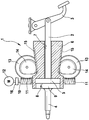
- the single figure shows a schematic and simplified axial sectional view of an electromechanical brake booster according to the invention.
- the electromechanical brake booster 1 has a piston rod 2, which is connected in an articulated manner to a brake pedal 3, which is not part of the brake booster 1, and a push rod 4.
- a hydraulic master brake cylinder not shown, can be actuated in a manner known per se, ie. H. a piston can be moved into the master brake cylinder.
- a so-called reaction disk 5 is arranged between the piston rod 2 and the pressure rod 4, via which a pressure force is transmitted from the piston rod 2 to the pressure rod 4.
- the piston of the master brake cylinder By depressing the brake pedal 3, the piston of the master brake cylinder, not shown, can be displaced into the master brake cylinder via the piston rod 2, the reaction disk 5 and the push rod 4, i. H. the master brake cylinder can be operated with muscle power in the manner described.
- the reaction disk 5 is made of rubber or a rubber-elastic plastic.
- the brake booster 1 has an amplifier body 6 with a coaxial through hole 7, in which the piston rod 2 is axially displaceably received.
- the amplifier body 6 is also axially displaceable, it tapers on its outside in the shape of a truncated cone in the direction of the push rod 4 and widens at its push rod end to a foot diameter of Truncated cone.
- the booster body 6 has a cylindrical countersink 8, in the bottom of which the through hole 7 opens and in which the reaction disk 5 lies and in which a plate-shaped foot 9 of the push rod 4 is received.
- a screw shaft 10 is arranged transversely to the amplifier body 6 and has two screws 11 rigidly connected to it or integral with it, which are located symmetrically on both sides of the amplifier body 6.
- the worm shaft 10 can be driven by an electric motor 12.
- the two worms 11 have pitches of the same size and opposite to each other. They mesh with worm gears 13 and form with these worm gears 11, 13. Due to the opposite inclinations of the worms 11 and thus due to the opposite movement of the two worm gears 11, 13, axial forces of the two worms 11 equalize when driving the worm gears 13, so that the Auger shaft 10 is free of axial force.
- a coupling 16 connects the worm shaft 10 in a rotationally fixed and axially movable manner to a motor shaft of the electric motor 12. By means of an axial displacement, the worm shaft 10 compensates for any tolerances in the gear paths, the gear paths are loaded equally.
- the worm wheels 13 are non-rotatable with spur gears 14 which are arranged opposite one another on both sides of the booster body 6.
- the spur gears 14 mesh with racks 15 of the booster body 6, which extend in the longitudinal direction of the booster body 6 in its frustoconical region. A distance between the two racks 15 decreases in the direction of the push rod 4.
- the spur gears 14 have a constant center distance from one another and from the booster body 6, they are eccentric, so that they are inclined to the axis and displacement direction of the booster body 6 of the racks 15th compensate.
- the spur gears 14 and the toothed racks 15 form rack and pinion gears 14, 15 which, due to the eccentricity of the spur gears 14 and the arrangement of the racks 15 obliquely to the direction of displacement, have changing ratios.
- the translation of the rack and pinion gear 14, 15 is smaller when the booster body 6 is displaced in the direction of the push rod 4, that is to say when the master brake cylinder (not shown) is actuated; with a displacement of the booster body 6 in the actuation direction of the master brake cylinder assumes a displacement speed of the booster body assuming a constant speed of the electric motor 12 6 from and assuming a constant driving torque of the electric motor 12 to an amplifier force of the brake booster 1.
- a straight course of the toothed racks 15 is not essential for the invention; in deviation from the embodiment shown, the toothed racks 15 can have any curvilinear course, in particular they can be rounded in a convex or concave manner.
- the shape of the spur gears 14 must be adapted to the course of the racks 15 so that the toothings always mesh.
- a variable center distance of the spur gears 14 from one another and from the booster body 6 is also conceivable.
- Racks 15 with a course parallel to the direction of displacement and concentric spur gears 14 are also possible, in which case the rack and pinion gears have a constant ratio (not shown).
- the spur gears 14 have a toothing only in the peripheral region which meshes or engages with the toothed racks 15 when they are rotated or pivoted.
- the booster force of the brake booster 1 is transmitted from the bottom of the countersink 8 of the booster body 6 via the reaction disk 5 to the foot 9 of the push rod 4.
- the reaction disc 5 adds the muscle force exerted on the piston rod 2 via the brake pedal 3 and the amplifying force exerted by the booster body 6 of the brake booster 1 and transmits the forces together as an actuating force to the foot 9 of the push rod 4.
- the two worm gears 11, 13 form a transfer case, that distributes a transmission input to two transmission paths.
- the gear input here is the worm shaft 10 or the drive torque of the electric motor 12.
- the two gear paths each comprise a worm gear 11, 13 and a rack and pinion gear 14, 15.
- the two rack and pinion gears 14, 15 form a combination gear with the booster body 6, which transmits the moments of the two Gear paths combined as an axially acting booster force on a gearbox output, namely the booster body 6. Due to the symmetrical structure and the symmetrical arrangement of the two transmission paths, both transmission paths transmit the same load, i.e. the same moments or forces, and the transmission output, namely the amplifier body 6 is acted upon symmetrically: neither a moment nor a transverse force acts on the amplifier body 6. Overall, the two worm gears 11, 13 and the two rack and pinion gears 14, 15 form a gear of the brake booster 1.
- the two transmission paths are multi-stage, namely two-stage.
- the worm gears 11, 13 form a first gear stage and the rack and pinion gears 14, 15 form a second gear stage of the gear paths.
- the worm gears 11, 13 are reduction gears, they convert a rotary drive movement into a rotary output movement.
- the rack and pinion gears 14, 15 are rotation / translation conversion gears which convert a rotary drive movement into a translational output movement.
- the rack and pinion gears 14, 15 have a changing transmission ratio.
Abstract
Die Erfindung betrifft einen elektromechanischen Bremskraftverstärker (1). Die Erfindung schlägt vor, den Bremskraftverstärker (1) mit zwei gegenläufigen Schneckengetrieben (11, 13) auszubilden, deren Axialkräfte einander kompensieren. Die Schneckengetriebe (11, 13) treiben Zahnstangengetriebe (14, 15) an, die eine rotatorische Antriebsbewegung in eine translatorische Abtriebsbewegung zur Betätigung eines Hauptbremszylinders umsetzen. Durch das Vorsehen zweier Getriebepfade ist die Belastung jedes Getriebepfads halbiert und eine Krafteinleitung in einen Verstärkerkörper (6), der einen Getriebeausgang bildet, symmetrisch.

Description
Die Erfindung betrifft einen elektromechanischen Bremskraftverstärker mit den Merkmalen des Oberbegriffs des Anspruchs 1.The invention relates to an electromechanical brake booster with the features of the preamble of claim 1.
Die Offenlegungsschrift
Einen weiteren elektromechanischen Bremskraftverstärker offenbart die Offenlegungsschrift
Der erfindungsgemäße elektromechanische Bremskraftverstärker mit den Merkmalen des Anspruchs 1 weist einen Elektromotor und ein Getriebe auf, das vom Elektromotor angetrieben wird. Das Getriebe weist ein Rotations-/Translations-Umsetzungsgetriebe auf, das eine rotatorische Antriebsbewegung des Elektromotors in eine translatorische Abtriebsbewegung zur Betätigung eines hydraulischen Hauptbremszylinders umsetzt. Als Rotations-/Translations-Umsetzungsgetriebe kommen beispielsweise ein Zahnstangengetriebe, ein Schraubgetriebe wie ein Spindeltrieb, ein Kugelumlaufgetriebe, ein Rollengewindetrieb, auch in Form eines Planetenrollen-Gewindetriebs, oder ein Zugmittelgetriebe in Betracht. Die Aufzählung ist nicht abschließend. Der Antrieb bzw. Eingang des Rotations-/Translations-Umsetzungsgetriebes muss nicht zwingend auch der Antrieb bzw. Eingang des Getriebes insgesamt sein, dem Rotations-/Translations-Umsetzungsgetriebe kann ein weiteres Getriebe oder eine Getriebestufe vorgeschaltet sein. Entsprechendes gilt für den Abtrieb bzw. Ausgang des Rotations-/Translations-Umsetzungsgetriebes, der nicht zwingend der Ausgang bzw. Abtrieb des Getriebes insgesamt sein muss. Dem Rotations-/Translations-Umsetzungsgetriebe kann ein weiteres Getriebe oder eine Getriebestufe nachgeschaltet sein.The electromechanical brake booster according to the invention with the features of claim 1 has an electric motor and a transmission which is driven by the electric motor. The transmission has a rotation / translation conversion transmission, which converts a rotary drive movement of the electric motor into a translational output movement for actuating a hydraulic master brake cylinder. Possible rotation / translation conversion gears are, for example, a rack and pinion gear, a screw gear such as a spindle drive, a ball screw gear, a roller screw drive, also in the form of a planetary roller screw drive, or a traction mechanism gear. The list is not exhaustive. The drive or input of the rotary / translation conversion gearbox need not necessarily be the drive or input of the gearbox as a whole, the rotary / translation conversion gearbox can be preceded by a further gearbox or a gear stage. The same applies to the output or output of the rotary / translation conversion gearbox, which does not necessarily have to be the output or output of the gearbox as a whole. A further gear or a gear stage can be connected downstream of the rotation / translation conversion gear.
Das Getriebe des erfindungsgemäßen elektromechanischen Bremskraftverstärkers weist ein Verteilergetriebe und ein Vereinigungsgetriebe auf. Das Verteilergetriebe und/oder das Vereinigungsgetriebe können Teile des Rotations-/Translations-Umsetzungsgetriebes umfassen. Das Verteilergetriebe verteilt einen Getriebeeingang auf mindestens zwei Getriebepfade, das Vereinigunsgetriebe vereinigt die Getriebepfade wieder auf einen gemeinsamen Getriebeausgang. Wie zum Rotations-/Translations-Umsetzungsgetriebe erläutert, muss der Getriebeeingang des Verteilergetriebes nicht der Getriebeeingang des Getriebes des Bremskraftverstärkers sein, sondern es kann dem Verteilergetriebe ein Getriebe oder eine Getriebestufe vorgeschaltet sein. Ebenso muss der Getriebeausgang des Vereinigungsgetriebes nicht der Ausgang des Getriebes insgesamt sein, sondern es kann dem Vereinigungsgetriebe ein weiteres Getriebe oder eine Getriebestufe nachgeschaltet sein. Die Getriebe können in jedem Getriebepfad vorhanden sein, wobei vorzugsweise jeder Getriebepfad gleiche Getriebe aufweist, was allerdings nicht zwingend ist. Die Getriebe können das Vereinigungsgetriebe bilden.The transmission of the electromechanical brake booster according to the invention has a transfer case and a combination gear. The transfer case and / or the combination gear can comprise parts of the rotation / translation conversion gear. The transfer case distributes a transmission input to at least two transmission paths, the combining transmission unites the transmission paths again to a common transmission output. As explained for the rotary / translational conversion gearbox, the gearbox input of the transfer case does not have to be the gearbox input of the transmission of the brake booster, but a gearbox or a gear stage can be connected upstream of the transfer gearbox. The gearbox output must also the union gearbox is not the output of the gearbox as a whole, but a further gearbox or a gear stage can be connected downstream of the union gearbox. The gears can be present in each gear path, each gear path preferably having the same gear, but this is not mandatory. The gears can form the union gear.
Ein Vorteil der Erfindung ist die Verteilung der Last des Getriebes, also eines vom Getriebe übertragenen Moments und/oder einer vom Getriebe übertragenen Kraft auf mindestens zwei Getriebepfade. Die Belastung der Getriebepfade ist dadurch verringert, was beispielsweise die Herstellung von Teilen des Getriebes aus Kunststoff anstatt aus Stahl ermöglicht. Ein weiterer Vorteil der Erfindung ist die Möglichkeit einer symmetrischen Ausbildung und einer symmetrischen Einleitung der translatorischen Abtriebsbewegung auf ein Ausgangsglied des Bremskraftverstärkers.An advantage of the invention is the distribution of the load of the transmission, that is to say a torque transmitted by the transmission and / or a force transmitted by the transmission, over at least two transmission paths. This reduces the load on the transmission paths, which enables, for example, the production of parts of the transmission from plastic instead of steel. Another advantage of the invention is the possibility of a symmetrical design and a symmetrical initiation of the translational output movement on an output element of the brake booster.
Die Unteransprüche haben vorteilhafte Ausgestaltungen und Weiterbildungen der im Anspruch 1 angegebenen Erfindung zum Gegenstand.The subclaims relate to advantageous refinements and developments of the invention specified in claim 1.
Anspruch 4 sieht eine mehrstufige Ausbildung des Getriebes vor, beispielsweise ist dem Rotations-/Translations-Umsetzungsgetriebe ein Untersetzungsgetriebe vorgeschaltet. Als Untersetzungsgetriebe kommen ein Schneckengetriebe, ein ggf. auch mehrstufiges Stirnradgetriebe, ein Planetengetriebe, ein Kegelradgetriebe oder ein Kronenradgetriebe in Betracht. Die Aufzählung ist nicht abschließend. Die Getriebe können das Verteilergetriebe bilden und/oder in jedem Getriebepfad vorhanden sein. Auch für eine mehrstufige Getriebeausbildung gilt, dass vorzugsweise jeder Getriebepfad gleiche Getriebe aufweist, was allerdings nicht zwingend für die Erfindung ist.
Anspruch 5 sieht ein Getriebe mit einer sich ändernden Übersetzung vor. Insbesondere verkleinert sich die Übersetzung bzw. vergrößert sich eine Untersetzung mit zunehmender Verschiebung eines Ausgangsglieds des Bremskraftverstärkers. Bei gleichem Antriebsmoment des Elektromotors wird die vom Bremskraftverstärker ausgeübte Verstärkerkraft größer, wogegen zu Beginn einer Bremsbetätigung eine Verschiebegeschwindigkeit des Ausgangsglieds des Bremskraftverstärkers bei gegebener Drehzahl des Elektromotors größer ist. Als Getriebe mit sich ändernder Übersetzung sind Kurvengetriebe, auch solche mit einer Zylinderkurve, bekannt. Zu Kurvengetrieben zählen auch Nockengetriebe mit einem drehend oder insbesondere schwenkend antreibbaren Nocken. Auch diese Aufzählung ist nicht abschließend. Gerade für Getriebe mit sich ändernder Übersetzung kann die Aufteilung auf mehrere solche Getriebe in mehreren Getriebepfaden von Vorteil sein, um die Belastung der einzelnen Getriebe zu verringern.
Die Erfindung wird nachfolgend anhand eines in der Zeichnung dargestellten Ausführungsbeispiels näher erläutert. Die einzige Figur zeigt eine schematisierte und vereinfachte Achsschnittdarstellung eines erfindungsgemäßen elektromechanischen Bremskraftverstärkers.The invention is explained in more detail below with reference to an embodiment shown in the drawing. The single figure shows a schematic and simplified axial sectional view of an electromechanical brake booster according to the invention.
Der in der Zeichnung dargestellte erfindungsgemäße elektromechanische Bremskraftverstärker 1 weist eine Kolbenstange 2, die gelenkig mit einem Bremspedal 3 verbunden ist, welches nicht Teil des Bremskraftverstärkers 1 ist, und eine Druckstange 4 auf. Mit der Druckstange 4 ist in an sich bekannter Weise ein nicht dargestellter hydraulischer Hauptbremszylinder betätigbar, d. h. ein Kolben ist in den Hauptbremszylinder hinein verschiebbar. Zwischen der Kolbenstange 2 und der Druckstange 4 ist eine sog. Reaktionsscheibe 5 angeordnet, über die eine Druckkraft von der Kolbenstange 2 auf die Druckstange 4 übertragen wird. Durch Niedertreten des Bremspedals 3 ist über die Kolbenstange 2, die Reaktionsscheibe 5 und die Druckstange 4 der Kolben des nicht dargestellten Hauptbremszylinders in den Hauptbremszylinder hinein verschiebbar, d. h. der Hauptbremszylinder ist in geschilderter Weise mit Muskelkraft betätigbar. Die Reaktionsscheibe 5 besteht aus Gummi oder einem gummielastischen Kunststoff.The electromechanical brake booster 1 according to the invention shown in the drawing has a
Der Bremskraftverstärker 1 weist einen Verstärkerkörper 6 mit einem koaxialen Durchgangsloch 7 auf, in dem die Kolbenstange 2 axial verschieblich aufgenommen ist. Der Verstärkerkörper 6 ist ebenfalls axial verschieblich, er verjüngt sich an seiner Außenseite kegelstumpfförmig in Richtung der Druckstange 4 und weitet sich an seinem druckstangenseitigen Ende zu einem Fußdurchmesser des Kegelstumpfs auf. Im druckstangenseitigen Ende weist der Verstärkerkörper 6 eine zylindrische Ansenkung 8 auf, in deren Grund das Durchgangsloch 7 mündet und in der die Reaktionsscheibe 5 einliegt und im Anschluss ein plattenförmiger Fuß 9 der Druckstange 4 aufgenommen ist.The brake booster 1 has an
Quer zum Verstärkerkörper 6 ist eine Schneckenwelle 10 angeordnet, die zwei starr mit ihr verbundene oder mit ihr einstückige Schnecken 11 aufweist, die sich symmetrisch beiderseits des Verstärkerkörpers 6 befinden. Antreibbar ist die Schneckenwelle 10 mit einem Elektromotor 12. Die beiden Schnecken 11 weisen gleich große, einander entgegen gesetzte Steigungen auf. Sie kämmen mit Schneckenrädern 13 und bilden mit diesen Schneckengetriebe 11, 13. Durch die entgegen gesetzten Steigungen der Schnecken 11 und damit durch die Gegenläufigkeit der beiden Schneckengetriebe 11, 13 gleichen sich Axialkräfte der beiden Schnecken 11 beim Antrieb der Schneckenräder 13 aus, so dass die Schneckenwelle 10 axialkraftfrei ist. Eine Kupplung 16 verbindet die Schneckenwelle 10 drehfest und axialbeweglich mit einer Motorwelle des Elektromotors 12. Durch eine Axialverschieblichkeit gleicht die Schneckenwelle 10 etwaige Toleranzen in den Getriebpfaden aus, die Getriebepfade werden gleich belastet.A
Die Schneckenräder 13 sind drehfest mit Stirnrädern 14, die einander gegenüberliegend beiderseits des Verstärkerkörpers 6 angeordnet sind. Die Stirnräder 14 kämmen mit Zahnstangen 15 des Verstärkerkörpers 6, die in Längsrichtung des Verstärkerkörpers 6 in dessen kegelstumpfförmigem Bereich verlaufen. Ein Abstand der beiden Zahnstangen 15 voneinander verkleinert sich in Richtung der Druckstange 4. Die Stirnräder 14 weisen einen konstanten Achsabstand voneinander und vom Verstärkerkörper 6 auf, sie sind exzentrisch, so dass sie den zur Achs- und Verschieberichtung des Verstärkerkörpers 6 schrägen Verlauf der Zahnstangen 15 ausgleichen. Die Stirnräder 14 und die Zahnstangen 15 bilden Zahnstangengetriebe 14, 15, die auf Grund der Exzentrizität der Stirnräder 14 und der zur Verschieberichtung schrägen Anordnung der Zahnstangen 15 sich ändernde Übersetzungen aufweisen. Die Übersetzung der Zahnstangengetriebe 14, 15 wird bei einer Verschiebung des Verstärkerkörpers 6 in Richtung der Druckstange 4, also bei einer Betätigung des nicht dargestellten Hauptbremszylinders, kleiner; bei einer Verschiebung des Verstärkerkörpers 6 in Betätigungsrichtung des Hauptbremszylinders nimmt bei angenommener konstanter Drehzahl des Elektromotors 12 eine Verschiebegeschwindigkeit des Verstärkerkörpers 6 ab und bei angenommenem konstantem Antriebsmoment des Elektromotors 12 eine Verstärkerkraft des Bremskraftverstärkers 1 zu. Ein gerader Verlauf der Zahnstangen 15 ist nicht zwingend für die Erfindung, abweichend von der dargestellten Ausführungsform können die Zahnstangen 15 einen an sich beliebigen, kurvenförmigen Verlauf aufweisen, insbesondere können sie konvex oder konkav gerundet sein. Die Form der Stirnräder 14 muss an den Verlauf der Zahnstangen 15 angepasst sein, so dass die Verzahnungen immer kämmen. Denkbar ist auch ein veränderlicher Achsabstand der Stirnräder 14 voneinander und vom Verstärkerkörper 6. Auch sind Zahnstangen 15 mit zur Verschieberichtung parallelem Verlauf und konzentrische Stirnräder 14 möglich, in diesem Fall weisen die Zahnstangengetriebe eine konstante Übersetzung auf (nicht dargestellt). Die Stirnräder 14 weisen eine Verzahnung nur in dem Umfangsbereich auf, der bei ihrer Drehung oder Verschwenkung mit den Zahnstangen 15 kämmt bzw. in Eingriff kommt.The
Die Verstärkerkraft des Bremskraftverstärkers 1 wird vom Grund der Ansenkung 8 des Verstärkerkörpers 6 über die Reaktionsscheibe 5 auf den Fuß 9 der Druckstange 4 übertragen. Die Reaktionsscheibe 5 addiert die über das Bremspedal 3 auf die Kolbenstange 2 ausgeübte Muskelkraft und die vom Verstärkerkörper 6 des Bremskraftverstärkers 1 ausgeübte Verstärkerkraft und überträgt die Kräfte gemeinsam als Betätigungskraft auf den Fuß 9 der Druckstange 4. Die beiden Schneckengetriebe 11, 13 bilden ein Verteilergetriebe, das einen Getriebeeingang auf zwei Getriebepfade verteilt. Getriebeeingang ist hier die Schneckenwelle 10 bzw. das Antriebsmoment des Elektromotors 12. Die beiden Getriebepfade umfassen jeweils ein Schneckengetriebe 11, 13 und ein Zahnstangengetriebe 14, 15. Die beiden Zahnstangengetriebe 14, 15 bilden mit dem Verstärkerkörper 6 ein Vereinigungsgetriebe, das die Momente der beiden Getriebepfade als axial wirkende Verstärkerkraft auf einen Getriebeausgang, nämlich den Verstärkerkörper 6, vereinigt. Durch den symmetrischen Aufbau und die symmetrische Anordnung beider Getriebepfade übertragen beide Getriebepfade die gleiche Last, also gleich große Momente oder Kräfte und der Getriebeausgang, nämlich der Verstärkerkörper 6 ist symmetrisch beaufschlagt: auf den Verstärkerkörper 6 wirken weder ein Moment noch eine Querkraft. Insgesamt bilden die beiden Schneckengetriebe 11, 13 und die beiden Zahnstangengetriebe 14, 15 bilden ein Getriebe des Bremskraftverstärkers 1.The booster force of the brake booster 1 is transmitted from the bottom of the
Die beiden Getriebepfade sind mehr-, nämlich zweistufig. Die Schneckengetriebe 11, 13 bilden eine erste Getriebestufe und die Zahnstangengetriebe 14, 15 eine zweite Getriebestufe der Getriebepfade. Die Schneckengetriebe 11, 13 sind Untersetzungsgetriebe, sie wandeln eine rotatorische Antriebsbewegung in eine rotatorische Abtriebsbewegung. Die Zahnstangengetriebe 14, 15 sind Rotations-/Translations-Umsetzungsgetriebe, die eine rotatorische Antriebsbewegung in eine translatorische Abtriebsbewegung wandeln. Wie bereits gesagt, weisen die Zahnstangengetriebe 14, 15 eine sich ändernde Übersetzung auf. Durch die Verteilung der Last auf zwei Getriebepfade ist eine Herstellung der Schneckenräder 13 aus Kunststoff möglich.The two transmission paths are multi-stage, namely two-stage. The worm gears 11, 13 form a first gear stage and the rack and pinion gears 14, 15 form a second gear stage of the gear paths. The worm gears 11, 13 are reduction gears, they convert a rotary drive movement into a rotary output movement. The rack and pinion gears 14, 15 are rotation / translation conversion gears which convert a rotary drive movement into a translational output movement. As already said, the rack and pinion gears 14, 15 have a changing transmission ratio. By distributing the load over two transmission paths, it is possible to manufacture the
Claims (8)
Applications Claiming Priority (3)
| Application Number | Priority Date | Filing Date | Title |
|---|---|---|---|
| DE200910001142 DE102009001142A1 (en) | 2009-02-25 | 2009-02-25 | Electromechanical brake booster |
| PCT/EP2009/067937 WO2010097135A1 (en) | 2009-02-25 | 2009-12-28 | Electromechanical brake booster |
| EP09796750.9A EP2401183B1 (en) | 2009-02-25 | 2009-12-28 | Elektromechanical brake booster |
Related Parent Applications (2)
| Application Number | Title | Priority Date | Filing Date |
|---|---|---|---|
| EP09796750.9A Division EP2401183B1 (en) | 2009-02-25 | 2009-12-28 | Elektromechanical brake booster |
| EP09796750.9A Division-Into EP2401183B1 (en) | 2009-02-25 | 2009-12-28 | Elektromechanical brake booster |
Publications (2)
| Publication Number | Publication Date |
|---|---|
| EP3628558A1 true EP3628558A1 (en) | 2020-04-01 |
| EP3628558B1 EP3628558B1 (en) | 2023-02-22 |
Family
ID=42347680
Family Applications (2)
| Application Number | Title | Priority Date | Filing Date |
|---|---|---|---|
| EP09796750.9A Active EP2401183B1 (en) | 2009-02-25 | 2009-12-28 | Elektromechanical brake booster |
| EP19203577.2A Active EP3628558B1 (en) | 2009-02-25 | 2009-12-28 | Elektromechanical brake booster |
Family Applications Before (1)
| Application Number | Title | Priority Date | Filing Date |
|---|---|---|---|
| EP09796750.9A Active EP2401183B1 (en) | 2009-02-25 | 2009-12-28 | Elektromechanical brake booster |
Country Status (10)
| Country | Link |
|---|---|
| US (1) | US9139186B2 (en) |
| EP (2) | EP2401183B1 (en) |
| JP (2) | JP5382747B2 (en) |
| KR (1) | KR101632595B1 (en) |
| CN (2) | CN102325680B (en) |
| BR (1) | BRPI0924280A2 (en) |
| DE (1) | DE102009001142A1 (en) |
| PL (1) | PL2401183T3 (en) |
| RU (1) | RU2533639C2 (en) |
| WO (1) | WO2010097135A1 (en) |
Families Citing this family (20)
| Publication number | Priority date | Publication date | Assignee | Title |
|---|---|---|---|---|
| US8464035B2 (en) * | 2009-12-18 | 2013-06-11 | Intel Corporation | Instruction for enabling a processor wait state |
| DE102010062785A1 (en) * | 2010-12-10 | 2012-06-14 | Robert Bosch Gmbh | Electromechanical brake booster with adjustable non-linear support force |
| DE102012014361A1 (en) * | 2012-07-20 | 2014-01-23 | Volkswagen Ag | Actuating device for a master cylinder of a motor vehicle |
| DE102012222949A1 (en) * | 2012-12-12 | 2014-06-12 | Robert Bosch Gmbh | Transmission device and electric motor brake booster |
| FR3005295B1 (en) * | 2013-05-03 | 2015-08-28 | Bosch Gmbh Robert | POWER BRAKE BRAKE SYSTEM |
| DE102013217443A1 (en) * | 2013-09-02 | 2015-03-05 | Robert Bosch Gmbh | Electromechanical brake booster for a brake system of a vehicle and method for mounting an electromechanical brake booster on and / or in a brake system for a vehicle |
| FR3017173A1 (en) * | 2014-01-31 | 2015-08-07 | Bosch Gmbh Robert | TRANSMISSION DEVICE FOR CONTROLLING THE ORGANIZATION TRANSLATION MOTION AND BRAKE SYSTEM EQUIPPED WITH SUCH A TRANSMISSION DEVICE FORMING A SERVOFREIN |
| DE102015220440B4 (en) | 2014-10-21 | 2023-10-05 | Hl Mando Corporation | Integrated dynamic braking device |
| DE102014226255A1 (en) * | 2014-12-17 | 2016-06-23 | Volkswagen Aktiengesellschaft | Electromechanical brake booster |
| DE102015217518A1 (en) * | 2015-09-14 | 2017-03-16 | Robert Bosch Gmbh | Electromechanical brake booster and method for producing an electromechanical brake booster |
| DE102015217548A1 (en) * | 2015-09-14 | 2017-03-16 | Robert Bosch Gmbh | Brake booster and braking device |
| DE102015012124A1 (en) | 2015-09-17 | 2017-03-23 | Lucas Automotive Gmbh | Electromechanical brake booster |
| DE102015012125A1 (en) | 2015-09-17 | 2017-03-23 | Lucas Automotive Gmbh | Assembly with a brake cylinder and an electromechanical brake booster |
| EP3350046B1 (en) | 2015-09-17 | 2019-10-23 | Lucas Automotive GmbH | Electromechanical brake force booster |
| US10097896B2 (en) | 2015-12-01 | 2018-10-09 | DISH Technologies L.L.C. | Recommend future video recordings for users from audiovisual content |
| US9986285B2 (en) | 2015-12-01 | 2018-05-29 | DISH Technologies L.L.C. | Set future video recordings from audiovisual content |
| DE102016101655A1 (en) * | 2016-01-29 | 2017-08-03 | Uwe Eisenbeis | Variable valve drive with adjusting screw with axial play |
| CN106476781A (en) * | 2016-11-04 | 2017-03-08 | 浙江力邦合信智能制动系统股份有限公司 | Deceleration of electrons booster |
| DE102016222859A1 (en) * | 2016-11-21 | 2018-05-24 | Audi Ag | Brake system for a motor vehicle |
| DE102018211549A1 (en) * | 2018-07-11 | 2020-01-16 | Robert Bosch Gmbh | Electromechanical brake booster and manufacturing method for an electromechanical brake booster |
Citations (5)
| Publication number | Priority date | Publication date | Assignee | Title |
|---|---|---|---|---|
| DE3031643A1 (en) | 1980-08-22 | 1982-04-01 | SWF-Spezialfabrik für Autozubehör Gustav Rau GmbH, 7120 Bietigheim-Bissingen | SERVO DEVICE, IN PARTICULAR FOR BRAKING REINFORCEMENT IN A MOTOR VEHICLE |
| EP0395262A2 (en) * | 1989-04-22 | 1990-10-31 | LUCAS INDUSTRIES public limited company | Brake actuator |
| DE10312207A1 (en) * | 2002-03-20 | 2003-10-30 | Advics Co | Electrically motorized device for controlling motor vehicle brakes uses a motor to pick up braking force through pressing a friction part |
| DE10327553A1 (en) | 2003-06-18 | 2005-01-13 | Volkswagen Ag | Electromechanical brake booster |
| DE102007018469A1 (en) * | 2007-04-19 | 2008-10-23 | Robert Bosch Gmbh | Electromechanical brake booster |
Family Cites Families (6)
| Publication number | Priority date | Publication date | Assignee | Title |
|---|---|---|---|---|
| US1612994A (en) * | 1925-05-02 | 1927-01-04 | Fred Mathews | Hand-brake booster |
| US2493377A (en) * | 1945-07-24 | 1950-01-03 | Thew Shovel Co | Automotive hydraulic braking system |
| RU2029891C1 (en) * | 1991-06-27 | 1995-02-27 | Харьковское Агрегатное Конструкторское Бюро | Electrohydraulic servo drive |
| JP2001050369A (en) * | 1999-08-06 | 2001-02-23 | Ricoh Co Ltd | Drive transmission device and image forming device using the device |
| DE102006010483B4 (en) * | 2006-03-07 | 2020-06-18 | Robert Bosch Gmbh | Disc brake for a vehicle with an integrated parking brake |
| CN2923453Y (en) * | 2006-05-15 | 2007-07-18 | 比亚迪股份有限公司 | Boosted braking system |
-
2009
- 2009-02-25 DE DE200910001142 patent/DE102009001142A1/en active Pending
- 2009-12-28 CN CN200980157427.XA patent/CN102325680B/en active Active
- 2009-12-28 BR BRPI0924280A patent/BRPI0924280A2/en not_active Application Discontinuation
- 2009-12-28 JP JP2011550435A patent/JP5382747B2/en active Active
- 2009-12-28 EP EP09796750.9A patent/EP2401183B1/en active Active
- 2009-12-28 RU RU2011139171/11A patent/RU2533639C2/en active
- 2009-12-28 US US13/203,239 patent/US9139186B2/en active Active
- 2009-12-28 CN CN201610086303.9A patent/CN105711576B/en active Active
- 2009-12-28 EP EP19203577.2A patent/EP3628558B1/en active Active
- 2009-12-28 KR KR1020117019699A patent/KR101632595B1/en active IP Right Grant
- 2009-12-28 PL PL09796750T patent/PL2401183T3/en unknown
- 2009-12-28 WO PCT/EP2009/067937 patent/WO2010097135A1/en active Application Filing
-
2013
- 2013-09-23 JP JP2013196331A patent/JP5886807B2/en active Active
Patent Citations (5)
| Publication number | Priority date | Publication date | Assignee | Title |
|---|---|---|---|---|
| DE3031643A1 (en) | 1980-08-22 | 1982-04-01 | SWF-Spezialfabrik für Autozubehör Gustav Rau GmbH, 7120 Bietigheim-Bissingen | SERVO DEVICE, IN PARTICULAR FOR BRAKING REINFORCEMENT IN A MOTOR VEHICLE |
| EP0395262A2 (en) * | 1989-04-22 | 1990-10-31 | LUCAS INDUSTRIES public limited company | Brake actuator |
| DE10312207A1 (en) * | 2002-03-20 | 2003-10-30 | Advics Co | Electrically motorized device for controlling motor vehicle brakes uses a motor to pick up braking force through pressing a friction part |
| DE10327553A1 (en) | 2003-06-18 | 2005-01-13 | Volkswagen Ag | Electromechanical brake booster |
| DE102007018469A1 (en) * | 2007-04-19 | 2008-10-23 | Robert Bosch Gmbh | Electromechanical brake booster |
Also Published As
| Publication number | Publication date |
|---|---|
| CN105711576B (en) | 2018-08-14 |
| JP5382747B2 (en) | 2014-01-08 |
| CN105711576A (en) | 2016-06-29 |
| DE102009001142A1 (en) | 2010-08-26 |
| CN102325680B (en) | 2016-03-16 |
| KR101632595B1 (en) | 2016-07-01 |
| RU2533639C2 (en) | 2014-11-20 |
| EP2401183B1 (en) | 2019-12-18 |
| RU2011139171A (en) | 2013-04-10 |
| EP3628558B1 (en) | 2023-02-22 |
| JP2012517935A (en) | 2012-08-09 |
| KR20110120294A (en) | 2011-11-03 |
| CN102325680A (en) | 2012-01-18 |
| JP2014028616A (en) | 2014-02-13 |
| PL2401183T3 (en) | 2020-05-18 |
| US9139186B2 (en) | 2015-09-22 |
| BRPI0924280A2 (en) | 2016-01-26 |
| US20120042647A1 (en) | 2012-02-23 |
| JP5886807B2 (en) | 2016-03-16 |
| EP2401183A1 (en) | 2012-01-04 |
| WO2010097135A1 (en) | 2010-09-02 |
Similar Documents
| Publication | Publication Date | Title |
|---|---|---|
| EP2401183B1 (en) | Elektromechanical brake booster | |
| EP3350046B1 (en) | Electromechanical brake force booster | |
| EP3350044B1 (en) | Assembly having a brake cylinder and an electromechanical brake booster | |
| DE102014113826B4 (en) | Adjustment of a disc brake, and a corresponding disc brake | |
| DE102016011361A1 (en) | ELECTRONIC DISC BRAKE | |
| DE10212879B4 (en) | Actuation mechanism for a parking brake | |
| EP2345569A1 (en) | Screw gearing for the steering of a motor vehicle | |
| EP2898233A1 (en) | Linear unit and method for the manufacture of a linear unit | |
| EP0447504B1 (en) | Electric motor servo-steering system | |
| DE102011082671A1 (en) | Drive unit for industrial truck, has housing, which is formed of gear housing part and hub housing part, where gear housing part incorporates spur wheel section and bearings of output side spur wheel of spur wheel section | |
| DE102014113055B4 (en) | Disc brake with an adjustment device | |
| DE19519310A1 (en) | Differential gear for braking system actuator | |
| DE102006007072B3 (en) | Device for mechanical release of motor-operated parking brake for motor vehicle has drive mechanism between cage and drive shaft designed so that their relative movement effects rotation of drive shaft in first rotational direction | |
| EP2636917A1 (en) | Wear adjustment device for disc brakes | |
| WO2020064044A1 (en) | Transmission unit for a motor vehicle transmission with a spur gear arranged rotatably on an intermediate shaft | |
| DE102005014560B4 (en) | Overhead steering for a vehicle | |
| DE4030625C2 (en) | Power steering gear | |
| EP0993561B1 (en) | Servo-actuator for a car clutch | |
| EP3997360A1 (en) | Electromechanical transmission and/or clutch actuator | |
| EP2517946B1 (en) | Rack-and-pinion steering gear for a vehicle | |
| EP2327539B1 (en) | Press or punching press with switchable planetary gear | |
| DE102008028265A1 (en) | Adjusting device for adjusting wear of e.g. brake lining, of disk brake for commercial motor vehicle, has overload clutch arranged between drive wheel and spur wheel, and freewheel clutch arranged in inner side of spur wheel | |
| WO1999012701A1 (en) | Zero play variable preload feedgear mechanism of a rack and pinion drive | |
| CH424410A (en) | Epicyclic gear with helical teeth | |
| DE102006010248A1 (en) | Electric motor with linkage system is used as an actuator for the clutch mechanism in an automobile |
Legal Events
| Date | Code | Title | Description |
|---|---|---|---|
| PUAI | Public reference made under article 153(3) epc to a published international application that has entered the european phase |
Free format text: ORIGINAL CODE: 0009012 |
|
| STAA | Information on the status of an ep patent application or granted ep patent |
Free format text: STATUS: THE APPLICATION HAS BEEN PUBLISHED |
|
| AC | Divisional application: reference to earlier application |
Ref document number: 2401183 Country of ref document: EP Kind code of ref document: P |
|
| AK | Designated contracting states |
Kind code of ref document: A1 Designated state(s): AT BE BG CH CY CZ DE DK EE ES FI FR GB GR HR HU IE IS IT LI LT LU LV MC MK MT NL NO PL PT RO SE SI SK SM TR |
|
| RAP1 | Party data changed (applicant data changed or rights of an application transferred) |
Owner name: ROBERT BOSCH GMBH |
|
| STAA | Information on the status of an ep patent application or granted ep patent |
Free format text: STATUS: REQUEST FOR EXAMINATION WAS MADE |
|
| 17P | Request for examination filed |
Effective date: 20201001 |
|
| RBV | Designated contracting states (corrected) |
Designated state(s): AT BE BG CH CY CZ DE DK EE ES FI FR GB GR HR HU IE IS IT LI LT LU LV MC MK MT NL NO PL PT RO SE SI SK SM TR |
|
| GRAP | Despatch of communication of intention to grant a patent |
Free format text: ORIGINAL CODE: EPIDOSNIGR1 |
|
| STAA | Information on the status of an ep patent application or granted ep patent |
Free format text: STATUS: GRANT OF PATENT IS INTENDED |
|
| RIC1 | Information provided on ipc code assigned before grant |
Ipc: F16H 35/02 20060101ALI20220812BHEP Ipc: F16H 19/00 20060101ALI20220812BHEP Ipc: F16H 1/22 20060101ALI20220812BHEP Ipc: B60T 13/74 20060101AFI20220812BHEP |
|
| INTG | Intention to grant announced |
Effective date: 20220909 |
|
| GRAS | Grant fee paid |
Free format text: ORIGINAL CODE: EPIDOSNIGR3 |
|
| GRAA | (expected) grant |
Free format text: ORIGINAL CODE: 0009210 |
|
| STAA | Information on the status of an ep patent application or granted ep patent |
Free format text: STATUS: THE PATENT HAS BEEN GRANTED |
|
| AC | Divisional application: reference to earlier application |
Ref document number: 2401183 Country of ref document: EP Kind code of ref document: P |
|
| AK | Designated contracting states |
Kind code of ref document: B1 Designated state(s): AT BE BG CH CY CZ DE DK EE ES FI FR GB GR HR HU IE IS IT LI LT LU LV MC MK MT NL NO PL PT RO SE SI SK SM TR |
|
| REG | Reference to a national code |
Ref country code: GB Ref legal event code: FG4D Free format text: NOT ENGLISH |
|
| REG | Reference to a national code |
Ref country code: CH Ref legal event code: EP |
|
| REG | Reference to a national code |
Ref country code: AT Ref legal event code: REF Ref document number: 1549327 Country of ref document: AT Kind code of ref document: T Effective date: 20230315 Ref country code: IE Ref legal event code: FG4D Free format text: LANGUAGE OF EP DOCUMENT: GERMAN |
|
| REG | Reference to a national code |
Ref country code: DE Ref legal event code: R096 Ref document number: 502009016454 Country of ref document: DE |
|
| REG | Reference to a national code |
Ref country code: SE Ref legal event code: TRGR |
|
| REG | Reference to a national code |
Ref country code: LT Ref legal event code: MG9D |
|
| P01 | Opt-out of the competence of the unified patent court (upc) registered |
Effective date: 20230509 |
|
| REG | Reference to a national code |
Ref country code: NL Ref legal event code: MP Effective date: 20230222 |
|
| PG25 | Lapsed in a contracting state [announced via postgrant information from national office to epo] |
Ref country code: PT Free format text: LAPSE BECAUSE OF FAILURE TO SUBMIT A TRANSLATION OF THE DESCRIPTION OR TO PAY THE FEE WITHIN THE PRESCRIBED TIME-LIMIT Effective date: 20230622 Ref country code: NO Free format text: LAPSE BECAUSE OF FAILURE TO SUBMIT A TRANSLATION OF THE DESCRIPTION OR TO PAY THE FEE WITHIN THE PRESCRIBED TIME-LIMIT Effective date: 20230522 Ref country code: NL Free format text: LAPSE BECAUSE OF FAILURE TO SUBMIT A TRANSLATION OF THE DESCRIPTION OR TO PAY THE FEE WITHIN THE PRESCRIBED TIME-LIMIT Effective date: 20230222 Ref country code: LV Free format text: LAPSE BECAUSE OF FAILURE TO SUBMIT A TRANSLATION OF THE DESCRIPTION OR TO PAY THE FEE WITHIN THE PRESCRIBED TIME-LIMIT Effective date: 20230222 Ref country code: LT Free format text: LAPSE BECAUSE OF FAILURE TO SUBMIT A TRANSLATION OF THE DESCRIPTION OR TO PAY THE FEE WITHIN THE PRESCRIBED TIME-LIMIT Effective date: 20230222 Ref country code: HR Free format text: LAPSE BECAUSE OF FAILURE TO SUBMIT A TRANSLATION OF THE DESCRIPTION OR TO PAY THE FEE WITHIN THE PRESCRIBED TIME-LIMIT Effective date: 20230222 Ref country code: ES Free format text: LAPSE BECAUSE OF FAILURE TO SUBMIT A TRANSLATION OF THE DESCRIPTION OR TO PAY THE FEE WITHIN THE PRESCRIBED TIME-LIMIT Effective date: 20230222 |
|
| PG25 | Lapsed in a contracting state [announced via postgrant information from national office to epo] |
Ref country code: PL Free format text: LAPSE BECAUSE OF FAILURE TO SUBMIT A TRANSLATION OF THE DESCRIPTION OR TO PAY THE FEE WITHIN THE PRESCRIBED TIME-LIMIT Effective date: 20230222 Ref country code: IS Free format text: LAPSE BECAUSE OF FAILURE TO SUBMIT A TRANSLATION OF THE DESCRIPTION OR TO PAY THE FEE WITHIN THE PRESCRIBED TIME-LIMIT Effective date: 20230622 Ref country code: GR Free format text: LAPSE BECAUSE OF FAILURE TO SUBMIT A TRANSLATION OF THE DESCRIPTION OR TO PAY THE FEE WITHIN THE PRESCRIBED TIME-LIMIT Effective date: 20230523 Ref country code: FI Free format text: LAPSE BECAUSE OF FAILURE TO SUBMIT A TRANSLATION OF THE DESCRIPTION OR TO PAY THE FEE WITHIN THE PRESCRIBED TIME-LIMIT Effective date: 20230222 |
|
| PG25 | Lapsed in a contracting state [announced via postgrant information from national office to epo] |
Ref country code: SM Free format text: LAPSE BECAUSE OF FAILURE TO SUBMIT A TRANSLATION OF THE DESCRIPTION OR TO PAY THE FEE WITHIN THE PRESCRIBED TIME-LIMIT Effective date: 20230222 Ref country code: RO Free format text: LAPSE BECAUSE OF FAILURE TO SUBMIT A TRANSLATION OF THE DESCRIPTION OR TO PAY THE FEE WITHIN THE PRESCRIBED TIME-LIMIT Effective date: 20230222 Ref country code: EE Free format text: LAPSE BECAUSE OF FAILURE TO SUBMIT A TRANSLATION OF THE DESCRIPTION OR TO PAY THE FEE WITHIN THE PRESCRIBED TIME-LIMIT Effective date: 20230222 Ref country code: DK Free format text: LAPSE BECAUSE OF FAILURE TO SUBMIT A TRANSLATION OF THE DESCRIPTION OR TO PAY THE FEE WITHIN THE PRESCRIBED TIME-LIMIT Effective date: 20230222 Ref country code: CZ Free format text: LAPSE BECAUSE OF FAILURE TO SUBMIT A TRANSLATION OF THE DESCRIPTION OR TO PAY THE FEE WITHIN THE PRESCRIBED TIME-LIMIT Effective date: 20230222 |
|
| REG | Reference to a national code |
Ref country code: DE Ref legal event code: R097 Ref document number: 502009016454 Country of ref document: DE |
|
| PG25 | Lapsed in a contracting state [announced via postgrant information from national office to epo] |
Ref country code: SK Free format text: LAPSE BECAUSE OF FAILURE TO SUBMIT A TRANSLATION OF THE DESCRIPTION OR TO PAY THE FEE WITHIN THE PRESCRIBED TIME-LIMIT Effective date: 20230222 |
|
| PLBE | No opposition filed within time limit |
Free format text: ORIGINAL CODE: 0009261 |
|
| STAA | Information on the status of an ep patent application or granted ep patent |
Free format text: STATUS: NO OPPOSITION FILED WITHIN TIME LIMIT |
|
| PGFP | Annual fee paid to national office [announced via postgrant information from national office to epo] |
Ref country code: GB Payment date: 20231220 Year of fee payment: 15 |
|
| 26N | No opposition filed |
Effective date: 20231123 |
|
| PG25 | Lapsed in a contracting state [announced via postgrant information from national office to epo] |
Ref country code: SI Free format text: LAPSE BECAUSE OF FAILURE TO SUBMIT A TRANSLATION OF THE DESCRIPTION OR TO PAY THE FEE WITHIN THE PRESCRIBED TIME-LIMIT Effective date: 20230222 |
|
| PGFP | Annual fee paid to national office [announced via postgrant information from national office to epo] |
Ref country code: SE Payment date: 20231219 Year of fee payment: 15 Ref country code: FR Payment date: 20231219 Year of fee payment: 15 |
|
| PGFP | Annual fee paid to national office [announced via postgrant information from national office to epo] |
Ref country code: DE Payment date: 20240227 Year of fee payment: 15 |