EP3628516A1 - Climatiseur modulaire pour un véhicule automobile et procédé de pré-configuration d'un climatiseur modulaire - Google Patents
Climatiseur modulaire pour un véhicule automobile et procédé de pré-configuration d'un climatiseur modulaire Download PDFInfo
- Publication number
- EP3628516A1 EP3628516A1 EP19198738.7A EP19198738A EP3628516A1 EP 3628516 A1 EP3628516 A1 EP 3628516A1 EP 19198738 A EP19198738 A EP 19198738A EP 3628516 A1 EP3628516 A1 EP 3628516A1
- Authority
- EP
- European Patent Office
- Prior art keywords
- air conditioning
- modules
- heat exchanger
- motor vehicle
- conditioning modules
- Prior art date
- Legal status (The legal status is an assumption and is not a legal conclusion. Google has not performed a legal analysis and makes no representation as to the accuracy of the status listed.)
- Granted
Links
- 238000004378 air conditioning Methods 0.000 title claims abstract description 339
- 238000000034 method Methods 0.000 title claims abstract description 14
- 239000003507 refrigerant Substances 0.000 claims abstract description 152
- 238000001816 cooling Methods 0.000 claims abstract description 37
- 238000010438 heat treatment Methods 0.000 claims description 29
- 238000010257 thawing Methods 0.000 claims description 8
- 238000005192 partition Methods 0.000 claims description 7
- 230000008859 change Effects 0.000 claims description 5
- 238000011144 upstream manufacturing Methods 0.000 claims description 5
- 230000003213 activating effect Effects 0.000 claims description 2
- 239000002826 coolant Substances 0.000 description 68
- 239000003570 air Substances 0.000 description 51
- 230000006870 function Effects 0.000 description 21
- 238000012546 transfer Methods 0.000 description 14
- 238000010586 diagram Methods 0.000 description 13
- 239000002918 waste heat Substances 0.000 description 10
- 239000007788 liquid Substances 0.000 description 9
- 238000011161 development Methods 0.000 description 6
- XLYOFNOQVPJJNP-UHFFFAOYSA-N water Substances O XLYOFNOQVPJJNP-UHFFFAOYSA-N 0.000 description 5
- 238000002485 combustion reaction Methods 0.000 description 4
- 230000008878 coupling Effects 0.000 description 4
- 238000010168 coupling process Methods 0.000 description 4
- 238000005859 coupling reaction Methods 0.000 description 4
- 239000007789 gas Substances 0.000 description 4
- 239000000203 mixture Substances 0.000 description 4
- 238000005057 refrigeration Methods 0.000 description 4
- 230000001105 regulatory effect Effects 0.000 description 4
- 230000001276 controlling effect Effects 0.000 description 3
- 230000007547 defect Effects 0.000 description 3
- 230000001419 dependent effect Effects 0.000 description 3
- 238000013461 design Methods 0.000 description 3
- 238000004146 energy storage Methods 0.000 description 3
- 238000005096 rolling process Methods 0.000 description 3
- 230000007704 transition Effects 0.000 description 3
- ATUOYWHBWRKTHZ-UHFFFAOYSA-N Propane Chemical compound CCC ATUOYWHBWRKTHZ-UHFFFAOYSA-N 0.000 description 2
- 239000012080 ambient air Substances 0.000 description 2
- 230000008901 benefit Effects 0.000 description 2
- 238000006243 chemical reaction Methods 0.000 description 2
- 238000004891 communication Methods 0.000 description 2
- 230000001186 cumulative effect Effects 0.000 description 2
- 238000007791 dehumidification Methods 0.000 description 2
- 230000007613 environmental effect Effects 0.000 description 2
- 230000008447 perception Effects 0.000 description 2
- 238000013517 stratification Methods 0.000 description 2
- 239000000126 substance Substances 0.000 description 2
- 230000032258 transport Effects 0.000 description 2
- 241000533950 Leucojum Species 0.000 description 1
- 230000004913 activation Effects 0.000 description 1
- 238000009835 boiling Methods 0.000 description 1
- 239000004020 conductor Substances 0.000 description 1
- 230000009849 deactivation Effects 0.000 description 1
- 230000006866 deterioration Effects 0.000 description 1
- 230000004069 differentiation Effects 0.000 description 1
- 238000009826 distribution Methods 0.000 description 1
- 238000005516 engineering process Methods 0.000 description 1
- 239000002360 explosive Substances 0.000 description 1
- 238000009434 installation Methods 0.000 description 1
- 239000000463 material Substances 0.000 description 1
- 238000005259 measurement Methods 0.000 description 1
- 238000003825 pressing Methods 0.000 description 1
- 230000008569 process Effects 0.000 description 1
- 239000001294 propane Substances 0.000 description 1
- 230000000717 retained effect Effects 0.000 description 1
- 238000000926 separation method Methods 0.000 description 1
- 238000005476 soldering Methods 0.000 description 1
- 239000007787 solid Substances 0.000 description 1
- 230000002123 temporal effect Effects 0.000 description 1
- 231100000331 toxic Toxicity 0.000 description 1
- 230000002588 toxic effect Effects 0.000 description 1
- 238000003466 welding Methods 0.000 description 1
Images


Classifications
-
- B—PERFORMING OPERATIONS; TRANSPORTING
- B60—VEHICLES IN GENERAL
- B60H—ARRANGEMENTS OF HEATING, COOLING, VENTILATING OR OTHER AIR-TREATING DEVICES SPECIALLY ADAPTED FOR PASSENGER OR GOODS SPACES OF VEHICLES
- B60H1/00—Heating, cooling or ventilating [HVAC] devices
- B60H1/00357—Air-conditioning arrangements specially adapted for particular vehicles
- B60H1/00371—Air-conditioning arrangements specially adapted for particular vehicles for vehicles carrying large numbers of passengers, e.g. buses
-
- B—PERFORMING OPERATIONS; TRANSPORTING
- B60—VEHICLES IN GENERAL
- B60H—ARRANGEMENTS OF HEATING, COOLING, VENTILATING OR OTHER AIR-TREATING DEVICES SPECIALLY ADAPTED FOR PASSENGER OR GOODS SPACES OF VEHICLES
- B60H1/00—Heating, cooling or ventilating [HVAC] devices
- B60H1/00507—Details, e.g. mounting arrangements, desaeration devices
- B60H1/00514—Details of air conditioning housings
- B60H1/00542—Modular assemblies
-
- B—PERFORMING OPERATIONS; TRANSPORTING
- B60—VEHICLES IN GENERAL
- B60H—ARRANGEMENTS OF HEATING, COOLING, VENTILATING OR OTHER AIR-TREATING DEVICES SPECIALLY ADAPTED FOR PASSENGER OR GOODS SPACES OF VEHICLES
- B60H1/00—Heating, cooling or ventilating [HVAC] devices
- B60H1/00642—Control systems or circuits; Control members or indication devices for heating, cooling or ventilating devices
- B60H1/00814—Control systems or circuits characterised by their output, for controlling particular components of the heating, cooling or ventilating installation
- B60H1/00878—Control systems or circuits characterised by their output, for controlling particular components of the heating, cooling or ventilating installation the components being temperature regulating devices
- B60H1/00899—Controlling the flow of liquid in a heat pump system
- B60H1/00907—Controlling the flow of liquid in a heat pump system where the flow direction of the refrigerant changes and an evaporator becomes condenser
-
- B—PERFORMING OPERATIONS; TRANSPORTING
- B60—VEHICLES IN GENERAL
- B60H—ARRANGEMENTS OF HEATING, COOLING, VENTILATING OR OTHER AIR-TREATING DEVICES SPECIALLY ADAPTED FOR PASSENGER OR GOODS SPACES OF VEHICLES
- B60H1/00—Heating, cooling or ventilating [HVAC] devices
- B60H1/00642—Control systems or circuits; Control members or indication devices for heating, cooling or ventilating devices
- B60H1/00814—Control systems or circuits characterised by their output, for controlling particular components of the heating, cooling or ventilating installation
- B60H1/00878—Control systems or circuits characterised by their output, for controlling particular components of the heating, cooling or ventilating installation the components being temperature regulating devices
- B60H2001/00961—Control systems or circuits characterised by their output, for controlling particular components of the heating, cooling or ventilating installation the components being temperature regulating devices comprising means for defrosting outside heat exchangers
Definitions
- the invention relates to a modular air conditioning device for a motor vehicle, preferably for an electrically driven motor vehicle, and a motor vehicle with a corresponding modular air conditioning device.
- the invention further relates to a method for preconfiguring a modular air conditioning device.
- the object of the invention is to provide an air conditioning device for a motor vehicle, a motor vehicle and a method for preconfiguration, with which disadvantages of the previous solutions can be avoided.
- the object of the invention is to provide an efficient air-conditioning device with high reliability, the heating and / or cooling capacity of which can be varied spatially and which can be flexibly adapted to changing operating conditions.
- Each of the refrigerant circuits comprises a compressor, a first heat exchanger for heat exchange with a vehicle exterior and / or a component of an electric drive, a first throttle device and a second heat exchanger for heat exchange with a vehicle interior and / or a component of an electric drive.
- each of the refrigerant circuits has a valve device, comprising a plurality of valves, for controlling a refrigerant flow within the refrigerant circuit, by means of which the first heat exchanger in a first operating mode M 1 , preferably for vehicle interior cooling and / or for cooling a component of an electric drive, upstream and in a second operating mode M 2 , preferably for vehicle interior heating and / or for heating a component of an electric drive, can be switched downstream of the second heat exchanger in the refrigerant circuit.
- a first operating mode M 1 preferably for vehicle interior cooling and / or for cooling a component of an electric drive
- M 2 preferably for vehicle interior heating and / or for heating a component of an electric drive
- the refrigerant circuit of an air conditioning module functions in the first operating mode M 1 as a refrigerator, preferably for cooling the vehicle interior and / or for cooling a component of an electric drive, and in the second operating mode M 2 as a heat pump, preferably for heating the vehicle interior and / or Heating a component of an electric drive.
- each of the air conditioning modules comprises a module control device for controlling the respective valve device and / or the compressor.
- the compressor is preferably one electrically driven compressor and / or the motor vehicle is an electrically driven motor vehicle.
- the air conditioning device comprises a central control device which is designed to determine a number of active air conditioning modules as a function of at least one monitored operating condition and / or to determine whether an active air conditioning module is operated in the first or second operating mode M 1 or M 2 .
- the air conditioning modules can also be operated in other operating modes.
- the operating modes of the individual air conditioning modules can preferably be defined independently of one another.
- the at least one monitored operating condition can be information relating to the operation of one or more air conditioning modules, for example the hours worked so far of the individual air conditioning modules, environmental information, for example an outside temperature, and / or a quantity derived from this information.
- the central control device can also be designed to monitor the at least one operating condition.
- a modular air conditioning device for a motor vehicle is thus advantageously provided, in which the individual air conditioning modules can simultaneously perform different functions, or the number of air conditioning modules operated can be variably set. Furthermore, the amount of heat emitted or absorbed by an individual air conditioning module and thus also the temperature level thereof can be determined independently of the other modules, this being coordinated by the central control device. In this context, one can also speak of a master-slave system, the central control device being the master unit and the air conditioning modules being the slave units which receive control commands from the central control device. It is also obvious to the person skilled in the art that the air conditioning device just described can comprise any number of air conditioning modules and is not limited to two air conditioning modules. Any number of operating conditions can also be monitored. This advantageously provides a modular and thus scalable or, depending on the area of use and / or motor vehicle, flexibly adaptable air conditioning device, in which an adequate air conditioning of the motor vehicle can also be ensured even in the event of a defect in individual modules.
- the at least one operating condition can be met if there is icing of at least one air conditioning module. Additionally or alternatively, the at least one operating condition can also be met if icing of at least one air conditioning module threatens but is not yet present.
- the fact that there is icing and / or impending icing can be indicated here, for example, by the fact that a temperature measured in the refrigerant circuit, in particular on the first or second heat exchanger, falls below a certain threshold value.
- the central control device can be designed to determine iced air conditioning modules and to operate them in a defrosting mode to reduce icing.
- the central control device can be designed to determine which of the available air conditioning modules are in an icy state and then to operate them, preferably only these, in a predetermined operating mode.
- the central control device can also be designed to determine the air conditioning modules that are at risk of icing and to operate them in a deicing mode to prevent icing. In this way, the operational safety of the air conditioning device can be increased in an advantageous manner, since failures of air conditioning modules due to icing are avoided as far as possible.
- the defrosting mode can include a change in the operating mode of at least one iced air conditioning module from the first operating mode M 1 to the second operating mode M 2 , or vice versa.
- the functions of the heat exchangers (evaporator and condenser) in the refrigerant circuit can be interchanged, which preferably enables heat to be introduced into the heat exchanger that previously functioned as an evaporator and is mostly affected by icing.
- An easy-to-implement de-icing mode is advantageously provided by simply switching the valve device.
- the deicing mode can also include activating or deactivating at least one iced air conditioning module.
- activation can generally be understood to mean the transition from an inoperative or non-functional state to an active state, preferably to an operation of the air conditioning module in the first or second operating mode M 1 or M 2 .
- a “deactivation” can be a transition from an active state to an inoperative or non-functional state, in particular to a state in which the air conditioning module has a refrigeration or Heat output of 0 watts can be understood.
- the defrosting mode can preferably include deactivating at least one iced air conditioning module, especially in the case of warm ambient temperatures. In this way, the ambient heat can advantageously be used to thaw iced areas without additional costs.
- the deicing mode can also include operating at least one iced air conditioning module in an operating point that deviates from the optimal operating point and / or is inefficient.
- the operating point which can also be referred to as the operating point, can be indicated by the temperature of the heat source medium, for example ambient air in operating mode M 2 , on the evaporator and the temperature of the heat sink medium, for example air of the vehicle interior in operating mode M 2 , on the condenser.
- the optimal operating point is the operating point with the highest efficiency.
- icing can be reduced by reducing the heating or cooling output provided by the corresponding air conditioning module.
- an air-conditioning module operated in defrosting mode also advantageously contributes to indoor air-conditioning.
- the central control device can be designed, according to a further aspect, to activate air conditioning modules that are not iced up for power compensation.
- one or more previously inactive air conditioning modules can be switched to the active state, preferably to an operation in the first or second operating mode M 1 or M 2 .
- the central control device can be designed to operate already activated, non-iced air conditioning modules at higher output.
- the expression “higher” power refers to a power of the air conditioning modules active at the time the defrosting mode is switched on.
- the power of only one or more active air conditioning modules can be increased.
- the loss of heating or cooling capacity due to the defrosting operation of some air conditioning modules can be compensated for by the other air conditioning modules. In this way, loss of comfort due to temperature fluctuations for the passengers is advantageously avoided.
- the at least one operating condition can be met if there is partial load operation.
- the operating condition can be met if the air conditioning device does not deliver its maximum output is requested.
- the fact that partial load operation is present can be indicated here, for example, by the fact that a measured power requested, delivered and / or consumed by the air conditioning device falls below a certain threshold value.
- the central control device can be designed to deactivate part of the air conditioning modules in order to optimize efficiency in partial load operation, preferably as a function of a current power requirement, the remaining active air conditioning modules being able to be operated with a higher degree of efficiency compared to operating all air conditioning modules.
- control device can be designed to optimize the number of active air conditioning modules as a function of a current performance requirement for the air conditioning device and the operating point-dependent efficiency of the individual air conditioning modules.
- it may be more efficient, for example, to operate two air conditioning modules at half power instead of one air conditioning module at full power. This can e.g. B.
- control device can also be set up on z.
- information stored in a memory relating to operating point-dependent key figures and / or characteristic curves of the individual air conditioning modules and / or to the measurement values of sensor devices, such as an outside temperature and / or current interior temperature in the motor vehicle. This advantageously enables an energy-saving and thus efficient operation of the modular air conditioning device.
- the at least one operating condition can be met if there is a working hour imbalance in the air conditioning modules.
- the central control device can be designed to log the working hours of the individual air conditioning modules, the size "working hours" describing the cumulative active operating time of the air conditioning modules. The fact that there is an imbalance in working hours can be indicated, for example, by one or more Working hours differences between two air conditioning modules exceed a certain threshold.
- the central control device can be designed to deactivate part of the air conditioning modules in part-load operation, the deactivated air conditioning modules on average having a higher number of working hours than the active air conditioning modules.
- the arithmetic mean of the working hours of the active air conditioning modules can be smaller than that of the deactivated, ie inactive, air conditioning modules. This advantageously increases the operational safety of the air conditioning device, since the individual air conditioning modules wear out as uniformly as possible.
- the central control device can be designed to preferably deactivate the air conditioning module with the most working hours - which can also be referred to as operating hours - in partial load operation.
- the central control device can be designed to primarily deactivate the air conditioning module, which has the most working hours when comparing the working hours of all the air conditioning modules. Any suitable size can be used to determine the hours worked, which is a measure of the previous operating load of an air conditioning module since it was commissioned.
- the central control device can also be designed to preferably activate the air conditioning module with the fewest working hours.
- the central control device can also be designed to preferably deactivate air conditioning modules with more working hours compared to an average working hours of all air conditioning modules and / or to activate climate control modules with fewer working hours compared to an average working hours of all air conditioning modules. All these regulations advantageously ensure that the working hours are distributed as evenly as possible among the individual air conditioning modules, which increases the service life of the individual modules.
- a motor vehicle preferably a commercial vehicle
- a modular air conditioning device as described in this document.
- This advantageously provides a motor vehicle with a modular and thus scalable, that is to say flexibly adaptable depending on the area of use, vehicle type and / or number of passengers, air conditioning device, in which an adequate air conditioning of the motor vehicle can also be ensured in the event of a defect in individual modules.
- the motor vehicle can be a preferably electrically driven omnibus with air conditioning modules arranged in the roof area in the longitudinal direction.
- the central control device can be designed to selectively activate all or part of the air-conditioning modules in order to optionally air-condition the entire interior or partial areas.
- the active air conditioning modules can all have the same or different current heating and / or cooling capacities or can all be operated in the same or different operating modes (for example operating mode M 1 or M 2 ). In other words, a motor vehicle with zonal air conditioning can be provided.
- the motor vehicle can also have at least one retractable and extendable partition for separating the interior into different interior areas, e.g. B. in a front and rear vehicle part.
- the size and / or division of the usable passenger compartment can be varied dynamically.
- each of the interior areas can be assigned at least one air conditioning module for air conditioning the respective interior area.
- the usable passenger space can be restricted to a front interior area which is air-conditioned by means of a first air conditioning module. There is no need for air conditioning of the separated, rear interior area.
- a second air conditioning module that is assigned to the rear interior area is not active. If the number of passengers increases, the entire available vehicle interior can be released for use by retracting the partition, which is now air-conditioned by the first and second air conditioning modules. In this way, energy-saving zonal air conditioning of a vehicle interior can advantageously be provided.
- the modular air conditioning device is preferably a modular air conditioning device for an electrically driven motor vehicle.
- the method initially includes determining a type and / or number of the air conditioning modules to be mounted on the motor vehicle depending on an area of application and / or the nominal power requirement of the motor vehicle.
- the area of application can be, for example, a hot country or cold country, for each of which a specific nominal power requirement for air conditioning is defined is.
- the specified type and / or number of air conditioning modules are then mounted on the motor vehicle.
- This connection can be understood by the expression "pre-configuration" the arrangement and composition of the modular air conditioning device before its planned commissioning.
- This also includes conversion measures as part of a change in the area of application, for example when the motor vehicle is moved from a hot to a cold country. This advantageously provides a possibility for dynamically adapting the air conditioning device to different areas of use.
- more air conditioning modules can be installed than if the application area is not a hot country.
- more air conditioning modules can be installed than if the area of application is not a cold country.
- a "hot country” can be an area with higher outside temperatures than the European area (e.g. Arab Emirates), while the term “cold country” can mean an area with lower outside temperatures (e.g. Iceland) compared to the Central European area can.
- an air conditioning device with three air conditioning modules for a city bus in Kunststoff (medium heating and cooling requirements), an air conditioning device with four air conditioning modules for a city bus in Granada (high cooling requirements) and an air conditioning device with five air conditioning modules for a city bus in Sweden (high heating requirements) be determined.
- the number of modules can thus be advantageously adapted to the respective climatic conditions.
- the step of determining a type and / or number of the air conditioning modules to be mounted on the motor vehicle can also take place as a function of the vehicle type and / or the vehicle size.
- one module may be sufficient for a van or a truck, while several modules are provided for a van or a truck with a cooling cabin.
- three air conditioning modules can be installed on a city bus, four on a coach and five on an articulated bus, while one module is sufficient for buses without air conditioning the passenger compartment. This advantageously enables an efficient and needs-based air conditioning device to be provided.
- the, preferably electrically driven, compressor of at least one air conditioning module can be a high-voltage compressor, which is preferably operated with a voltage between 250-800 V.
- the compressor which can also be referred to as a compressor and serves to compress the refrigerant, can be designed to require at least a voltage of 250 V for correct operation.
- the compressor or the high-voltage compressor can be designed, for example, in the form of a rolling piston, a scroll compressor, a reciprocating piston compressor, a screw compressor and / or a turbocompressor. This advantageously ensures that the air conditioning module can also provide sufficient cooling or heating output in the case of large-volume vehicle interiors (e.g. buses).
- the second heat exchanger of at least one air conditioning module can be a coolant / refrigerant heat exchanger, preferably in the form of a plate heat exchanger.
- a heat exchanger is understood to be an apparatus which can transfer heat from one medium to another and vice versa.
- the first medium is a coolant, for example water
- the second medium is a refrigerant, for example CO 2 .
- Coolants or refrigerants are understood to be gaseous, liquid or solid substances or mixtures of substances which can be used to remove heat.
- refrigerants can also transfer heat against a temperature gradient in a refrigeration cycle, while refrigerants are only able to transport entropy along the temperature gradient to a location at a lower temperature in one refrigeration cycle.
- the second heat exchanger can be connected to a coolant circuit, which will be referred to below as the first coolant circuit for better differentiation.
- This first coolant circuit can also be referred to as a first pump Pump for conveying coolant and a third heat exchanger, preferably an air / coolant heat exchanger, for heat exchange with the vehicle interior.
- a fan can also be arranged on the third heat exchanger to regulate the air flow into the vehicle interior.
- the heating or cooling of the vehicle interior cannot take place through direct heat exchange between the refrigerant circuit and the vehicle interior, but via an indirect heat exchange via the first coolant circuit.
- This increases operational safety, since the entry of often dangerous refrigerant (e.g. CO 2 ) into the passenger compartment - for example in the event of a leak - can be minimized, since the refrigerant circuit is not in direct contact with a vehicle interior, especially not with one Driver's workplace, stands.
- the refrigerant circuit of at least one air conditioning module can comprise a fourth heat exchanger, which is preferably designed as a coolant / refrigerant heat exchanger. This can be connected in parallel to the second heat exchanger in the first operating mode M 1 and in parallel to the first heat exchanger in the refrigerant circuit in the second operating mode M 2 .
- the fourth heat exchanger can be connected to a second coolant circuit, which is preferably designed to cool an electrical energy store and / or an electrical machine. Additionally or alternatively, the second coolant circuit can also be designed to cool a front box, power electronics and / or an electrical converter.
- the second coolant circuit can further comprise a pump, referred to as the second pump, for circulating the coolant, for example water, and / or can be thermally coupled to an electrical machine and / or an electrical energy store, preferably via a cooling plate.
- the coolant of the second coolant circuit can also flow around and / or flow through at least part of an electrical machine and / or an electrical energy store.
- this advantageously achieves cooling of an electrical energy store in an electrical machine, power electronics and / or an electrical converter of a motor vehicle, while at the same time the waste heat of these components can be used for heating the vehicle interior.
- the refrigerant circuit of at least one air conditioning module can comprise a fifth heat exchanger which is connected in series to the first and second heat exchangers in the refrigerant circuit both in the first operating mode M 1 and in the second operating mode M 2 .
- the refrigerant of the refrigerant circuit flows through the first, second and fifth heat exchangers in succession both in the first and second operating modes M 1 and M 2 , the sequence of the flow through being able to vary depending on the operating mode.
- the area of application of the corresponding air conditioning module can be expanded by means of the fifth heat exchanger, since further advantageous functions of the refrigerant circuit can be implemented, which are discussed in more detail below.
- the fifth heat exchanger can be an air / refrigerant heat exchanger, preferably in the form of a finned tube and / or a microchannel heat exchanger, which can be thermally coupled to an air line for heat exchange with the vehicle interior.
- the fifth heat exchanger can also be thermally coupled to an air flow flowing into the passenger compartment.
- the fifth heat exchanger can be thermally coupled to an air flow that was previously in thermal contact with the second heat exchanger. That is, an air stream can first exchange heat with the second heat exchanger and then heat with the fifth heat exchanger before flowing into the passenger compartment.
- the fifth heat exchanger can also be a coolant / refrigerant heat exchanger, preferably in the form of a plate heat exchanger, which can be connected to a coolant circuit referred to as the third coolant circuit.
- a water-based coolant can be used as the coolant in the third coolant circuit - as for all other coolant circuits in the entire document.
- the third coolant circuit can additionally include a third pump, a sixth heat exchanger, preferably an air / refrigerant heat exchanger, and / or a seventh heat exchanger, preferably a coolant / refrigerant heat exchanger, for exchanging heat with the vehicle interior.
- the third coolant circuit can comprise one or more valves through which different flow paths can be implemented in the third coolant circuit.
- a fan for regulating the air flow can be arranged in the region of the sixth heat exchanger.
- the seventh heat exchanger can serve to dehumidify the air flow flowing to the passenger compartment
- the sixth heat exchanger advantageously enables further heat input into the passenger compartment, that is to say spatially separate from the seventh heat exchanger.
- the spatially offset inflow into the passenger compartment can advantageously counteract vertical air stratification.
- the refrigerant circuit of at least one air conditioning module can be thermally coupled directly to an electrical energy store, preferably a traction battery.
- the refrigerant circuit of at least one air conditioning module can also be thermally coupled directly to an electrical machine.
- a direct coupling means that the refrigerant circuit is also immediate, i.e. H. without intermediate coolant circuit, can give off heat to an electrical machine and / or an electrical energy store or can absorb heat from these components.
- the refrigerant of the refrigerant circuit preferably also flows around and / or through at least part of an electrical machine and / or an electrical energy store.
- At least one of the air conditioning modules can comprise at least one air flap and / or at least one fan.
- the fan which in this context can also be referred to as a blower, fan and / or flow machine, can convey air to and / or to the respective air conditioning module, for example by means of a rotating impeller.
- the control device can also be designed to control the air quantity conveyed by the respective air conditioning module, for example by increasing / reducing a speed of the fan. This is preferably done independently of the mode of operation of the further air conditioning modules.
- this not only achieves a more adjustable air conditioning of a passenger compartment.
- the refrigerant circuit can use at least one air conditioning module CO 2 and / or propane as the refrigerant.
- CO 2 air conditioning module
- the advantage of using CO 2 is that CO 2 is neither toxic, explosive nor flammable, and that it meets all current environmental requirements.
- the refrigerant circuit of at least one air conditioning module can also include a collector for collecting refrigerant, preferably as a buffer store for refrigerant.
- the collector can also be designed to separate gaseous and liquid refrigerants or to separate oil at the bottom of the collector.
- the collector can also be called a separator.
- the refrigerant circuit of at least one air conditioning module can also comprise an additional cooler, which thermally couples a region of the refrigerant circuit between the throttle device and the first heat exchanger to a region of the refrigerant circuit before the input of the compressor.
- the auxiliary cooler can therefore also be referred to as an internal heat exchanger because it transfers heat within the refrigerant circuit.
- the additional cooler is preferably implemented by means of a heat exchanger, but other forms of heat coupling can also be used without leaving the scope of the invention. The additional cooler advantageously enables the efficiency of the cycle to be increased.
- the motor vehicle can be an electric vehicle, preferably an electric bus.
- the motor vehicle can be driven exclusively by means of an electrical machine (electric motor). Since no waste heat from an internal combustion engine is available for heating the passenger compartment in such vehicles, the present invention advantageously enables reliable air conditioning of the interior, particularly for electric vehicles.
- the motor vehicle can also be a motor vehicle operated by an internal combustion engine or a hybrid motor vehicle.
- at least one of the air conditioning modules can be arranged in the area of the roof of the motor vehicle. All of the air conditioning modules are particularly preferably arranged in the area of the roof and / or on the roof of the motor vehicle. This advantageously enables a space-saving and easy-to-maintain assembly of the modular air conditioning device.
- each of the air conditioning modules can be assigned to an air conditioning area of the vehicle interior for zonal air conditioning of the vehicle interior.
- the air-conditioning area which can also be referred to as the air-conditioning zone, is to be understood to mean an area of the interior of the motor vehicle which can be cooled or heated as independently as possible from other areas of the vehicle interior by means of an air-conditioning module assigned to this area.
- air-conditioning areas or climatic zones of an interior in which people are staying can thus be air-conditioned while air-conditioning areas that are not currently used cannot be air-conditioned. For example, in the case of a bus on a business trip, i. H.
- the central control device can be designed to activate a part of the air conditioning modules and / or to deactivate a part of the air conditioning modules in accordance with a requirement.
- the stipulation which can also be referred to as stipulation, can be predefined by the user, for example by selecting certain air conditioning modules to be activated or deactivated using an input device.
- the stipulation can also be an area of application, a number of passengers and / or a spatial distribution of passengers in the vehicle interior.
- the central control device can also be designed to operate a part of the air conditioning modules in the first operating mode M 1 and / or a part of the air conditioning modules in the second operating mode M 2 in accordance with a requirement. This advantageously enables optimal use of the existing modules, depending on the requirements.
- FIG. 1 shows a modular air conditioning device 100 for a motor vehicle 30 according to an embodiment of the invention.
- the air conditioning device 100 comprises at least two - in the present embodiment three - air conditioning modules 10a, 10b, 10c, each of which comprises a refrigerant circuit 1a, 1b, 1c and a module control device 2a, 2b, 2c.
- Each of the module control devices 2a, 2b, 2c can control the amount of heat absorbed and / or given off by the individual air conditioning modules 10a, 10b, 10c by controlling the components of their assigned refrigerant circuit 1a, 1b, 1c described in more detail below.
- each of the module control devices 2a, 2b, 2c is connected to a higher-level central control device 20.
- the latter can send control commands to the individual module control devices 2a, 2b, 2c, as well as receive information relating to the respective air conditioning module 10a, 10b, 10c.
- the air conditioning device 100 can also include suitable data lines, for example in the form of CAN and / or LIN bus lines.
- the central control device 20 is designed to determine a number of active air conditioning modules 10a, 10b, 10c and / or to determine whether an active air conditioning module 10a, 10b, 10c is operated in the first or second operating mode M 1 or M 2 depending on at least one monitored operating condition .
- each air conditioning module 10a, 10b, 10c can be defined independently of one another. Furthermore, the air conditioning modules 10a, 10b, 10c can also optionally be operated or operated in other operating modes without leaving the scope of the invention.
- a modular air conditioning device 100 in which the individual air conditioning modules 10a, 10b, 10c can perform different functions at the same time, or the number of air conditioning modules 10a, 10b, 10c operated can be variably set. Furthermore, the amount of heat emitted or absorbed by an individual air conditioning module 10a, 10b, 10c can also be determined independently of the other modules, this being coordinated by the central control device 20. In this context, one can also speak of a master-slave system, the central control device 20 being the master unit and the air conditioning modules 10a, 10b, 10c being the slave units which receive control commands from the central control device 20.
- the air conditioning device 100 just described is not limited to three air conditioning modules 10a, 10b, 10c, but can also comprise any number of further modules without departing from the scope of the invention.
- a modular and thus scalable air conditioning device 100 which can be flexibly adapted depending on the area of use and / or motor vehicle, is provided in the present case.
- Figure 13 shows an exemplary operating state of a modular air conditioning device 100 for a motor vehicle 30 according to the previously described embodiment of the invention.
- a basic idea of the invention is that the individual air conditioning modules 10a, 10b, 10c can simultaneously perform different functions, or the number of active, ie operated, air conditioning modules 10a, 10b, 10c can be variably set.
- a subset of all air conditioning modules 10a, 10b, 10c can be present, for example, in the first operating mode M 1 and another subset of all air conditioning modules 10a, 10b, 10c in the second operating mode M 2 .
- the dashed lines in Figure 13 illustrates also a subset of all air conditioning modules 10a, 10b, 10c - in the present case the air conditioning modules 10a and 10b - to be active, while another subset of all air conditioning modules 10a, 10b, 10c - in the present case the air conditioning module 10c - is not active (deactivated).
- the central control device 20 is designed to determine a number of active air conditioning modules 10a, 10b depending on at least one monitored operating condition and / or to determine whether an active air conditioning module 10a, 10b im first or second operating mode M 1 or M 2 is operated.
- the monitored operating condition can be met if one of the air conditioning modules 10a, 10b, 10c - in the present case, for. B.
- Air conditioning module 10c - has significantly more cumulative working hours than the other air conditioning modules 10a and 10b.
- the control device 20 can be set up to preferably deactivate air conditioning modules with many working hours in order to adjust the working hours in a partial load operation.
- Part-load operation can be understood to mean an operating situation in which not all air-conditioning modules 10a, 10b, 10c or the full power of all existing air-conditioning modules 10a, 10b, 10c are required to meet a specified performance requirement.
- the performance requirements can be met solely by operating the air conditioning modules 10a and 10b, the active air conditioning modules 10a and 10b both being able to be operated both in the first or second operating mode, or else in each case in different operating modes.
- the working hours can advantageously be distributed as evenly as possible among the individual air conditioning modules 10a, 10b, 10c, which increases the service life of the individual air conditioning modules 10a, 10b, 10c.
- Figure 14 shows, by way of example, the temporal course of operating states of a modular air conditioning device 100 for a motor vehicle 30 according to the embodiment just described.
- the starting point here is the upper illustration i, in which the air conditioning modules 10a and 10b are operated in the second operating mode M 2 , while the air conditioning module 10c is not active, ie deactivated.
- the two air conditioning modules 10a and 10b can provide both the same heating power and a different heating power.
- one of the air conditioning modules - in the present case the air conditioning module 10b - can ice up. This is shown in Figure ii, the icing of the air conditioning module 10b being symbolized by a snowflake. Because due to the icing, the air conditioning module 10b can no longer achieve its full performance or since the air conditioning module 10b can be damaged by the icing, it is advantageous to de-ice this air conditioning module 10b.
- the central control device 20 is therefore designed, if there is icing of at least one air conditioning module 10b, to determine iced air conditioning modules 10b and to operate them in a deicing mode to reduce icing.
- the central control device 20 can be designed, for example, to measure one or more temperatures in the refrigerant circuits 1a, 1b, 1c, in particular on the heat exchangers of the refrigerant circuits 1a, 1b, 1c. If one of these temperatures falls below a certain threshold value, this can indicate icing, so that an operating condition for starting the icing operation is fulfilled.
- this operating condition can also be met if icing of at least one air conditioning module 10a, 10b, 10c only threatens, but is not yet present.
- the central control device 20 can also be designed to activate the previously inactive air conditioning module - in the present example, the air conditioning module 10c - so that at least part of the previous performance of the air conditioning module 10b is applied by the air conditioning module 10c for power compensation.
- the previously active air conditioning module 10a can also be operated at a higher output. In this way, loss of comfort due to temperature fluctuations for the passengers can advantageously be avoided.
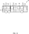
- FIG 12 shows a schematic representation of a motor vehicle 30 according to an embodiment of the invention.
- the motor vehicle 30 in the present case is an omnibus, preferably a purely electrically driven omnibus.
- This has a modular air conditioning device 100.
- the air conditioning device 100 in this case comprises at least two - in the present embodiment three - air conditioning modules 10a, 10b, 10c, preferably arranged on the vehicle roof, each comprising a refrigerant circuit 1a, 1b, 1c and a module control device 2a, 2b, 2c (not shown) , it being obvious to the person skilled in the art that the motor vehicle 30 can also comprise more than three air conditioning modules 10a, 10b, 10c.
- the motor vehicle 30 comprises a central control device 20, which is configured for each of the three air conditioning modules 10a, 10b, 10c can be operated independently of one another in a first operating mode M 1 for vehicle interior cooling or in a second operating mode for vehicle interior heating M 2 .
- the air conditioning modules 10a, 10b, 10c can optionally also be operated in other operating modes.
- the individual air conditioning modules 10a, 10b, 10c can also be completely deactivated, ie rendered inoperative.
- a motor vehicle 30 is thus provided with a modular air conditioning device 100, in which the individual air conditioning modules 10a, 10b, 10c can perform different functions simultaneously, or the number of air conditioning modules 10a, 10b, 10c operated can be variably set.
- the central control device 20 is connected to the air conditioning modules 10a, 10b, 10c via corresponding communication or data lines, for example in the form of CAN and / or LIN bus lines. Accordingly, the central control device 20 can both send control commands to the individual module control devices 2a, 2b, 2c, as well as receive information relating to the respective air conditioning module 10a, 10b, 10c from them. In this context, one can also speak of a master-slave system. Furthermore, the refrigerant circuits 1a, 1b, 1c of the individual air conditioning modules 10a, 10b, 10c can be identical, for example according to one of the exemplary embodiments described above.
- the individual air conditioning modules 10a, 10b, 10c can also have different embodiments of the refrigerant circuits 1a, 1b, 1c.
- the individual air conditioning modules 10a, 10b, 10c are preferably also each assigned to a specific air conditioning area 16a, 16b, 16c of the vehicle interior, as a result of which zonal air conditioning of the vehicle interior can be achieved.
- the air-conditioning module 10c can be assigned to an air-conditioning area 16c around the driver's seat, the air-conditioning module 10b to a central air-conditioning area 16b of the motor vehicle 30 and the air-conditioning module 10a to a rear air-conditioning area 16a of the motor vehicle 30.
- the omnibus is thus, for example, on an operational trip, ie that only the bus driver is inside the vehicle.
- the air conditioning module 10c can be used for air conditioning, while the air conditioning modules 10a and 10b are inactive.
- the motor vehicle 30 can comprise at least one retractable and extendable partition 17 for separating the interior into different interior areas 18a, 18b.
- the partition 17 divides the interior into a rear first interior area 18a and a front second interior area 18b.
- each interior area 18a, 18b can be assigned at least one air conditioning module 10a, 10b, 10c for air conditioning the respective interior area 18a, 18b.
- the air conditioning module 10a is assigned to the first interior area 18a and the air conditioning modules 10b and 10c are assigned to the second interior area 18b. Accordingly, it can be seen that the interior areas 18a, 18b can be identical to the aforementioned air-conditioning areas 16a, 16b, 16c - as is the case here in the rear part of the bus - but can also denote different areas. In the present case, the second interior area 18b has two air conditioning areas 16b and 16c. Overall, a motor vehicle 30 with a modular and thus scalable or, depending on the area of use and / or motor vehicle 30, flexibly adaptable air conditioning device 100 is thus advantageously provided.
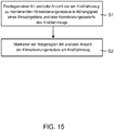
- FIG. 12 shows a flow diagram of a method for preconfiguring a modular air conditioning device 100 for a motor vehicle 30 according to an embodiment of the invention.
- the modular air conditioning device 100 is preferably a modular air conditioning device 100 for an electrically driven motor vehicle 30.
- the method includes determining a type and / or number of the air conditioning modules 10 a, 10 b, 10 c to be mounted on the motor vehicle 30 as a function of a Field of application and / or nominal power requirement of the motor vehicle 30.
- the field of application can be, for example, a hot country or cold country, for each of which a specific nominal power requirement for air conditioning is defined.
- the specified type and / or number of the air conditioning modules are then mounted on the motor vehicle 30.
- pre-configuration to mean the arrangement and composition of the modular air conditioning device 100 prior to its planned commissioning.
- This also includes conversion measures as part of a change in the area of application, for example when the motor vehicle 30 is moved from a hot to a cold country. This advantageously provides a possibility for dynamically adapting the air conditioning device 100 to different areas of use.
- the refrigerant circuits 1a, 1b, 1c of the individual air conditioning modules 10a, 10b, 10c will be discussed in detail. However, it should be mentioned here that the following embodiments only show exemplary embodiments of individual refrigerant circuits 1a, 1b, 1c.
- the entire air conditioning device Depending on the motor vehicle or intended use, 100 can comprise several identical air conditioning modules 10a, 10b, 10c, but also a combination of air conditioning modules 10a, 10b, 10c with different refrigerant circuits 1a, 1b, 1c, which are now described in more detail.
- FIG. 2 shows a refrigerant circuit 1a, 1b, 1c of an air conditioning module 10a, 10b, 10c according to a first embodiment of the invention.
- the entire refrigerant circuit 1a, 1b, 1c is shown here, wherein depending on the operating mode of the air conditioning module 10a, 10b, 10c, only certain areas of the illustrated refrigerant circuit 1a, 1b, 1c are actually flowed through by the refrigerant.
- the aspect of the flow guidance which differs depending on the operating mode is discussed in more detail later in the description of FIG. 6.
- the refrigerant circuit 1a, 1b, 1c shown to start or keep a refrigerant flow in motion the refrigerant circuit 1a, 1b, 1c comprises a compressor 3, preferably driven by an electric motor 15.
- the compressor 3, which can also be referred to as a compressor, can be used here for example in the form of a rolling piston, a scroll compressor, a reciprocating piston compressor, a screw compressor and / or a turbo compressor.
- the refrigerant, preferably CO 2 is compressed by means of this component.
- the refrigerant circuit 1a, 1b, 1c comprises a first heat exchanger W 1 for heat exchange with a vehicle exterior and / or a component of an electric drive, a first throttle device 4a, for example in the form of an expansion valve and / or a capillary tube, and a second heat transfer W 2 for heat exchange with a vehicle interior and / or a component of an electric drive.
- the two heat exchangers W 1 , W 2 as air / refrigerant heat exchangers, for. B. as finned tube heat transfers, flat tube heat exchangers and / or microchannel heat exchangers.
- finned tube heat transfer should generally be understood to mean an apparatus which comprises at least one tubular component which has fins made of a material which is a good conductor of heat in order to improve the transferable heat or cooling capacity.
- the ribs preferably serve to enlarge the pipe surface and can be produced on the outside, for example by rolling, by soldering or welding, by pressing or grooving into the pipe wall.
- heat exchangers in particular air / refrigerant heat exchangers, can also be used without departing from the scope of the invention.
- first operating mode M 1 and second operating mode M 2 are used below to differentiate these operating modes.
- the first operating mode M 1 should preferably serve to cool the vehicle interior and / or cool a component of an electric drive, while the second operating mode M 2 should preferably serve to heat the vehicle interior and / or to heat a component of an electric drive.
- the two operating modes M 1 and M 2 are achieved by correspondingly interconnecting the valves 5 a -5 d , so that in the first operating mode M 1 the first heat exchanger W 1 upstream and in the second operating mode M 2 the first heat exchanger W 1 downstream from the second Heat exchanger W 2 is switched.
- the first heat exchanger in the first operating mode M 1, can function as a condenser or gas cooler and the second heat exchanger W 2 as an evaporator, while in the second operating mode the first heat exchanger functions as an evaporator and the second heat exchanger W 2 as a condenser or gas cooler.
- valves 5 a -5 h are connected to a module control device 2a, 2b, 2c, not shown, the latter - as in Figure 1 shown - are in connection with a higher-level central control device 20.
- control commands can be transmitted to the valves 5 a -5 h , for example.
- B. can switch between an open position in a closed position or vice versa.
- the central control device 20 or the module control devices 2a, 2b, 2c can also be used to regulate the air flow generated by the fans 9 a -9 d and / or the refrigerant flow generated by the compressor 3.
- the amount of heat absorbed and / or emitted by an air conditioning module 10a, 10b, 10c and / or an air flow flowing from and / or into the air conditioning module 10a, 10b, 10c can thus be regulated independently of the other air conditioning modules 10a, 10b, 10c that are present.
- the main refrigerant circuit can also include other optional components, including - as in the in Figure 2 Embodiment shown - comprise a collector 11 for the separation of gaseous and liquid refrigerants. Since part of the - possibly present - liquid refrigerant, preferably in the bottom area of the collector 11, can also be retained or collected in this component, the collector 11 can also be referred to as a collector or a collecting container. In this way, it can advantageously be ensured that, if possible, only gaseous refrigerant enters the compressor 3, since liquids could cause damage here. Furthermore, the refrigerant circuit 1a, 1b, 1c can also include an additional cooler 12.
- this thermal coupling is symbolized by the chain line.
- the additional cooler 12 is preferably realized by means of a heat exchanger, but other forms of heat coupling can also be used without leaving the scope of the invention.
- the additional cooler 12 advantageously enables the effectiveness of the compressor to be increased.
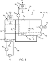
- FIG 3 shows a schematic circuit diagram of a refrigerant circuit 1a, 1b, 1c according to a second embodiment of the invention.
- the first embodiment shown here is formed in the main refrigerant circuit in the second heat exchanger W 2 instead of as an air / refrigerant heat exchanger as a coolant / refrigerant heat exchanger.
- the coolant / refrigerant heat exchanger can be designed, for example, in the form of a plate heat exchanger.
- a plate heat exchanger is generally understood to be an apparatus which comprises wave-shaped plates which are composed such that the medium to be warmed up and then the heat-emitting medium flows in the successive intermediate spaces.
- the plate pack is preferably sealed to the outside and between the media and is held together, for example, with clamping screws.
- the second heat exchanger W 2 is also connected to a coolant circuit, which is referred to below as the first coolant circuit 6 a for better distinction.
- the second heat exchanger is W 2 thus flows through both the refrigerant, preferably CO 2, the refrigerant circuit 1a, 1b, 1c as well as the coolant, preferably water, of the first coolant circuit 6a, and no refrigerant exchange between the both circuits he follows.
- the second heat exchanger W 2 enables heat transfer from the refrigerant circuit 1a, 1b, 1c on the first coolant circuit 6a or vice versa.
- the first coolant circuit 6a comprises a pump for circulating the coolant, which is to be referred to as the first pump 7a for distinction, and a further heat exchanger, which is to be referred to below as the third heat exchanger W 3 .
- the third heat exchanger W 3 is an air / coolant heat exchanger for exchanging heat with a vehicle interior, wherein - without departing from the scope of the invention - other types of heat exchangers can also be used.
- a fan 9 c can also be arranged on the third heat exchanger W 3 .
- the peculiarity of this second embodiment is that the heating or cooling of the vehicle interior does not take place through direct heat exchange between the refrigerant circuit 1a, 1b, 1c and the vehicle interior, but via an indirect heat exchange via the first coolant circuit 6a.
- the operational safety of the air conditioning device 100 can be increased in an advantageous manner, since the risk of direct leakage of refrigerants, such as CO 2 , which are often dangerous for humans, can be minimized in the passenger compartment.
- this fourth heat exchanger W 4 is also designed as a coolant / coolant heat exchanger and is connected to a coolant circuit, which for better distinction is to be referred to as the second coolant circuit 6 b.
- This second coolant circuit 6b is particularly preferably a coolant circuit for cooling an electrical machine and / or an electrical energy store 8, for example a traction battery.
- the second coolant circuit 6b can further comprise a pump, referred to as the second pump 7b, for circulating the coolant, for example water, and / or be thermally coupled to an electrical machine and / or an electrical energy store 13, preferably via a cooling plate .
- the coolant of the second coolant circuit 6b can be used also flow around and / or flow through at least part of an electrical machine and / or an electrical energy store 13.
- the fourth heat exchanger W 4 including a second coolant circuit 6b connected to it makes it possible, on the one hand, to advantageously cool the electrical energy store 8 and / or the electrical machine, while at the same time the waste heat from these components can be used to heat the vehicle interior.
- FIG. 4 shows a schematic circuit diagram of a refrigerant circuit 1a, 1b, 1c according to a third embodiment of the invention.
- this embodiment in addition to the main refrigerant circuit common to all the embodiments - comprising the compressor 3, the first heat exchanger W 1 , the first throttle device 4a, the second heat exchanger W 2 and the valves 5 a -5 d - this embodiment in turn also has the - already discussed - optional component collectors 11 and additional cooler 12.
- the refrigerant circuit 1a, 1b, 1c also comprises a heat exchanger, referred to as the fifth heat exchanger W 5 , and two further valves 5 e and 5 f .
- the fifth heat exchanger W 5 is designed as an air / refrigerant heat exchanger, for example in the form of a finned tube heat exchanger, a flat tube heat exchanger and / or a microchannel heat exchanger, for heat exchange with a vehicle interior.
- the fifth heat exchanger W 5 can be thermally coupled to an air line 8 a leading air to the passenger compartment or directly to an air flow flowing into the passenger compartment.
- the fifth heat exchanger W 5 can be thermally coupled to an air flow that was previously in thermal contact with the second heat exchanger W 2 .
- an air flow can first exchange heat with the second heat exchanger W 2 and then heat with the fifth heat exchanger W 5 before it flows into the passenger compartment.
- the air flow flowing into the passenger compartment can be divided after the heat exchange with the second heat exchanger W 2 , in the present case into a part flowing through air line 8 a and into air line 8 b .
- the air stream flowing through air line 8 b is conducted directly into the passenger compartment, the air stream flowing through air line 8 a can exchange heat with the fifth heat exchanger W 5 before it enters the passenger compartment.
- the fifth heat exchanger W 5 can be connected in series to the first and second heat exchangers W 1 , W 2 both in the first operating mode M 1 and in the second operating mode M 2 .
- the fifth heat exchanger W 5 advantageously enables in the refrigerant circuit 1a, 1b, 1c, a dehumidification of the air previously cooled by means of the second heat exchanger W 2 , which is also shown in the two operating modes M 1 and M 2 Figure 6 is discussed in more detail.
- FIG 5 shows a schematic circuit diagram of a refrigerant circuit 1a, 1b, 1c according to a fourth embodiment of the invention, which is a further development of the third embodiment just described ( Figure 4 ) represents.
- the refrigerant circuit 1a, 1b, 1c in the present case includes one - in the course of the description Figure 3 discussed - fourth heat exchanger W 4 and a second throttle device 4b.
- the fourth heat exchanger W 4 is again designed as a coolant / refrigerant heat exchanger and can be connected in parallel in the first operating mode M 1 to the second heat exchanger W 2 and in the second operating mode M 2 in parallel with the first heat exchanger W 1 .
- this fourth heat exchanger W 4 can be connected to a second coolant circuit 6 b, which is preferably used for cooling an electrical machine and / or an electrical energy store 8.
- the second coolant circuit 6b can comprise a pump for conveying coolant and / or one or more heat exchangers, referred to as the second pump 7b, or can be thermally coupled to an electrical machine and / or an electrical energy store 13.
- cooling of the electrical energy store 8 and / or of the electrical machine, while at the same time using its waste heat for heating the vehicle interior can advantageously also be achieved.
- Figure 6 shows the refrigerant paths in the first operating mode M 1 (upper figure) and second operating mode M 2 (lower figure) for the fourth embodiment of the invention just described ( Figure 5 ).
- first operating mode M 1 for cooling the vehicle interior (upper figure) - driven by the compressor 3 - gaseous refrigerant and the compressor 3 pressurized under high pressure flows via the open valve 5 a in the direction of the first heat exchanger W 1
- the optional fifth Heat exchanger W5 can be integrated into the refrigerant circuit 1a, 1b, 1c by opening the valves 5 e and 5 f .
- the first heat exchanger W 1 and the optional fifth heat exchanger W 5 function in the operating mode M 1 as condensers and / or gas coolers.
- the gaseous refrigerant preferably CO 2
- this heat is transferred to the vehicle exterior and, in the optional case, the fifth heat exchanger W 5 to a - in air line 8 a - air flow to the vehicle interior.
- the refrigerant then passes through the first throttle device 4a, by means of which the refrigerant is expanded, ie the pressure is reduced, as a result of which the boiling temperature of the refrigerant is reduced.
- the refrigerant evaporates while absorbing heat from the surroundings of the second heat exchanger W 2 .
- the second heat exchanger W 2 functions as an evaporator.
- the heat preferably comes from the interior of the vehicle, which cools it down.
- the second heat transfer W 2 is connected to an air line 8b which can lead air to the vehicle interior.
- the refrigerant then flows via the opened valve 5c back to the compressor 3, in which the gaseous refrigerant is compressed and the process begins again.
- part of the refrigerant can also flow to the compressor 3 via a further throttle device, referred to as the second throttle device 4 b, and a fourth heat transfer W 4 .
- the fourth heat exchanger W 4 is preferably thermally coupled to an electrical energy store 13 via a second coolant circuit 6 b.
- the fourth heat exchanger W 4 also functions here as an evaporator and preferably absorbs excess waste heat from the electrical energy store 13 and transports it to the fourth heat exchanger W 4 by means of the second coolant circuit 6b.
- a necessary cooling of the electrical energy store 13 and / or another electrical machine that is in thermal contact with the second coolant circuit 6b can be achieved.
- the waste heat from these components is not released into the vehicle environment unused, but is used via the fifth heat exchanger W5 to dehumidify the air previously cooled by means of the second heat exchanger W 2 . That is, In this operating mode, air from the vehicle interior and / or the vehicle exterior can be cooled by means of the second heat exchanger W 2 , then slightly warmed and thus dehumidified by means of the fifth heat exchanger W 5 and finally passed into the vehicle interior.
- the lower figure shows the flow control or the refrigerant paths in the case of the second operating mode M 2 for vehicle interior heating.
- the gaseous refrigerant in the operating mode M 2 does not initially flow as before to the first but to the second heat exchanger W 2 , the optional fifth heat exchanger W 5 being connected upstream of this in the present embodiment.
- the valve 5 a and 5 f closed while the valves 5 e and 5 d are open. If the optional fifth heat exchanger W 5 together with the corresponding optional valves 5 e and 5 f are not available, you can move the valve 5 a accordingly (see Figure 2 ) the same redirection of the refrigerant flow can be achieved.
- Both the fifth heat exchanger W 5 and the second heat exchanger W 2 function in the second operating mode M 2 as condensers or gas coolers.
- gaseous refrigerant is partially or completely liquefied there, releasing heat. This amount of heat can be given off to an air flow to the vehicle interior, whereby this can be heated.
- the liquefied refrigerant flows further in the main refrigerant circuit to the first throttle device 4 a and is expanded there before it enters the first heat exchanger W 1 .
- the first heat exchanger W 1 functions as an evaporator, ie the initially still liquid refrigerant evaporates, heat being removed from the surroundings of the first heat exchanger W 1 - in the present case the vehicle exterior.
- the gaseous refrigerant then flows again to the compressor 3 via the opened valve 5 b and the cycle begins again.
- part of the refrigerant can in turn be expanded via the optional second throttle device 4b and enter the fourth heat exchanger W 4 before it reaches the compressor 3.
- the fourth heat exchanger W 4 thus functions in the second operating mode M 2 - as well as in the first operating mode M 1 - as an evaporator and absorbs waste heat, for example from an electrical energy store 13 thermally coupled to the fourth heat exchanger W 4 .
- FIG. 7 shows a schematic circuit diagram of a refrigerant circuit 1a, 1b, 1c according to a fifth embodiment of the invention.
- the main refrigerant circuit essentially corresponds to that in Figure 4 shown third embodiment.
- the fifth heat exchanger W 5 is now designed as a coolant / coolant heat exchanger, preferably as a plate heat exchanger, and is connected to a coolant circuit which is referred to below as the third coolant circuit 6c.
- the third coolant circuit 6c further comprises the following components: a pump, referred to as the third pump 7c, the valves 5 h and 5 g, as well as two heat transfers, which for better distinction are referred to as the sixth and seventh heat exchangers W 6 , W 7 .
- the sixth heat exchanger W 6 enables a further heat input into the passenger compartment, ie spatially separated from the seventh heat transfer W 7 , e.g. B. in the floor area of the vehicle interior, in an advantageous manner counteract vertical air stratification.
- a fan 9 d for regulating the air flow can be arranged in the region of the sixth heat exchanger W 6 and can be regulated independently of the further fans 9 a and 9 b .
- the present fifth embodiment of the invention comprises an optional eighth heat exchanger W 8 in the area of fresh air intake.
- the eighth heat exchanger W 8 is preferably designed in the form of an air / air heat exchanger. In this way, the waste heat from the passenger compartment can advantageously be used to preheat the fresh air flowing in from the vehicle exterior.
- Figure 8 shows the flow guidance for the just in Figure 7 fifth embodiment of the invention shown in the first and second operating modes M 1 and M 2 .
- the flow guidance in the first operating mode M 1 for vehicle interior cooling is shown in the upper illustration and the flow guidance in the second operating mode M 2 for vehicle interior heating is shown in the lower illustration.
- the flow guidance again corresponds to that below Figure 6 discussed case, why for corresponding details on the figure description Figure 6 is referred.
- the embodiment shown switches between the two operating modes M 1 and M 2 also by means of the valves 5 a -5 f .
- valves 5 a , 5 c , 5 e , and 5 f are open, while the valves 5 b and 5 d are closed.
- the valves 5 b , 5 d and 5 e are open and the valves 5 a , 5 c and 5 f are closed.
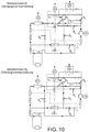
- FIG. 9 shows a schematic circuit diagram of a refrigerant circuit 1a, 1b, 1c of an air conditioning module 10a, 10b, 10c according to a sixth embodiment of the invention.
- the present refrigerant circuit 1a, 1b, 1c essentially corresponds to the embodiment previously shown in FIG. 7, but additionally has a second throttle device 4b and a fourth heat exchanger W 4 including a second coolant circuit 6b connected thereto for energy storage cooling.
- Possible variants and functions of the second coolant circuit 6b have already been discussed in detail above and are, for example, the description of the figures Figure 3 refer to.
- Figure 10 shows the flow guidance for the just in Figure 9 shown sixth embodiment of the invention in the first and second operating modes M 1 and M 2 .
- the design of the main refrigerant circuit does not differ from the previous embodiments, which is why further explanations are unnecessary.
- Figure 11 is a legend to those in the Figures 2-10 shown schematic circuit diagrams.
- the symbols used in accordance with DIN 1861 are, however, additionally labeled with the corresponding component names for reasons of clarity.
Landscapes
- Physics & Mathematics (AREA)
- Thermal Sciences (AREA)
- Engineering & Computer Science (AREA)
- Mechanical Engineering (AREA)
- Air-Conditioning For Vehicles (AREA)
Priority Applications (1)
| Application Number | Priority Date | Filing Date | Title |
|---|---|---|---|
| PL19198738T PL3628516T3 (pl) | 2018-09-25 | 2019-09-20 | Modułowe urządzenie klimatyzacyjne dla pojazdu mechanicznego oraz sposób wstępnej konfiguracji modułowego urządzenia klimatyzacyjnego |
Applications Claiming Priority (1)
| Application Number | Priority Date | Filing Date | Title |
|---|---|---|---|
| DE102018123558.5A DE102018123558A1 (de) | 2018-09-25 | 2018-09-25 | Modulare Klimatisierungsvorrichtung für ein Kraftfahrzeug, Kraftfahrzeug mit einer entsprechenden modularen Klimatisierungsvorrichtung sowie Verfahren zur Vorkonfiguration einer modularen Klimatisierungsvorrichtung |
Publications (2)
| Publication Number | Publication Date |
|---|---|
| EP3628516A1 true EP3628516A1 (fr) | 2020-04-01 |
| EP3628516B1 EP3628516B1 (fr) | 2022-03-30 |
Family
ID=67998386
Family Applications (1)
| Application Number | Title | Priority Date | Filing Date |
|---|---|---|---|
| EP19198738.7A Active EP3628516B1 (fr) | 2018-09-25 | 2019-09-20 | CLIMATISEUR MODULAIRE POUR UN VÉHICULE AUTOMOBILE ET
PROCÉDÉ DE PRÉ-CONFIGURATION D'UN CLIMATISEUR MODULAIRE |
Country Status (4)
| Country | Link |
|---|---|
| EP (1) | EP3628516B1 (fr) |
| DE (1) | DE102018123558A1 (fr) |
| HU (1) | HUE058693T2 (fr) |
| PL (1) | PL3628516T3 (fr) |
Cited By (2)
| Publication number | Priority date | Publication date | Assignee | Title |
|---|---|---|---|---|
| EP3915815A1 (fr) | 2020-05-29 | 2021-12-01 | Konvekta Aktiengesellschaft | Appareil amélioré de refroidissement et de chauffage pour un véhicule, ainsi que système et véhicule correspondants et procédé associé |
| US11642936B2 (en) | 2021-09-30 | 2023-05-09 | Midea Group Co., Ltd. | Recreational vehicle air conditioning system with load sharing |
Citations (5)
| Publication number | Priority date | Publication date | Assignee | Title |
|---|---|---|---|---|
| EP1127767A1 (fr) * | 2000-02-23 | 2001-08-29 | Behr Industrietechnik GmbH & Co. | Dispositif de conditionnement d'air et procédé pour son fonctionnement |
| DE602004003044T2 (de) * | 2003-05-05 | 2007-06-28 | Carrier Corp. | Konfiguration für modulare deckenklimaanlage |
| CN201890111U (zh) * | 2010-11-22 | 2011-07-06 | 南京奥特佳冷机有限公司 | 基于多温区模块化智能温度控制的电动大客车空调节能系统 |
| EP2660086A1 (fr) | 2012-05-02 | 2013-11-06 | MAN Truck & Bus AG | Système de circuit pour véhicule utilitaire |
| EP2719966A1 (fr) * | 2011-06-08 | 2014-04-16 | Mitsubishi Electric Corporation | Dispositif de réfrigération/conditionnement d'air |
Family Cites Families (16)
| Publication number | Priority date | Publication date | Assignee | Title |
|---|---|---|---|---|
| US5927398A (en) | 1996-06-22 | 1999-07-27 | Carrier Corporation | Device identification system for HVAC communication network |
| DE10161254A1 (de) | 2001-12-13 | 2003-07-03 | Konvekta Ag | Klimatisierungseinrichtung für ein Fahrzeug |
| EP2946953A1 (fr) | 2008-10-23 | 2015-11-25 | Bsst Llc | Système cvc multimode à dispositif thermoélectrique |
| JP5446694B2 (ja) * | 2008-12-15 | 2014-03-19 | 株式会社デンソー | エジェクタ式冷凍サイクル |
| US8082743B2 (en) | 2009-02-20 | 2011-12-27 | Tesla Motors, Inc. | Battery pack temperature optimization control system |
| DE102009019607B4 (de) | 2009-04-30 | 2023-08-03 | Bayerische Motoren Werke Aktiengesellschaft | Fahrzeug mit einem elektrischen Antrieb und einer Einrichtung zur Klimatisierung des Fahrgastraums |
| US9091451B2 (en) | 2009-06-05 | 2015-07-28 | Hobart Brothers Company | Modular heating, ventilating, air conditioning, and refrigeration systems and methods |
| DE102009059240B4 (de) | 2009-12-21 | 2013-08-01 | Webasto Ag | Kraftfahrzeug-Kühlsystem |
| JP5646303B2 (ja) | 2010-11-30 | 2014-12-24 | 三洋電機株式会社 | 空気調和装置 |
| US9452659B2 (en) | 2012-12-31 | 2016-09-27 | GM Global Technology Operations LLC | Method and apparatus for controlling a combined heating and cooling vapor compression system |
| DE102014203895B4 (de) | 2014-03-04 | 2018-08-16 | Konvekta Ag | Kälteanlage |
| DE102015003119A1 (de) | 2015-03-11 | 2016-09-15 | Man Truck & Bus Ag | Fahrzeug, insbesondere Hybridfahrzeug oder elektrisch angetriebenes Fahrzeug, mit einer Elektromaschine sowie Verfahren zum Betrieb einer zugeordneten Klimaanlage |
| DE102015004308A1 (de) * | 2015-04-01 | 2016-10-06 | Man Truck & Bus Ag | Verfahren und Vorrichtung zum Betreiben einer Omnibus-Klimaanlge |
| DE102016119231B4 (de) * | 2016-10-10 | 2022-03-31 | Konvekta Aktiengesellschaft | Klimaanlage für ein Fahrzeug mit verbesserter Temperaturregelung und Verfahren dazu |
| CN106476565B (zh) | 2016-10-25 | 2019-03-26 | 珠海格力电器股份有限公司 | 一种热泵空调机组、其控制方法及电动客车 |
| DE102016124305A1 (de) * | 2016-12-14 | 2018-06-14 | Aurora Konrad G. Schulz Gmbh & Co. Kg | Omnibus |
-
2018
- 2018-09-25 DE DE102018123558.5A patent/DE102018123558A1/de active Pending
-
2019
- 2019-09-20 PL PL19198738T patent/PL3628516T3/pl unknown
- 2019-09-20 EP EP19198738.7A patent/EP3628516B1/fr active Active
- 2019-09-20 HU HUE19198738A patent/HUE058693T2/hu unknown
Patent Citations (5)
| Publication number | Priority date | Publication date | Assignee | Title |
|---|---|---|---|---|
| EP1127767A1 (fr) * | 2000-02-23 | 2001-08-29 | Behr Industrietechnik GmbH & Co. | Dispositif de conditionnement d'air et procédé pour son fonctionnement |
| DE602004003044T2 (de) * | 2003-05-05 | 2007-06-28 | Carrier Corp. | Konfiguration für modulare deckenklimaanlage |
| CN201890111U (zh) * | 2010-11-22 | 2011-07-06 | 南京奥特佳冷机有限公司 | 基于多温区模块化智能温度控制的电动大客车空调节能系统 |
| EP2719966A1 (fr) * | 2011-06-08 | 2014-04-16 | Mitsubishi Electric Corporation | Dispositif de réfrigération/conditionnement d'air |
| EP2660086A1 (fr) | 2012-05-02 | 2013-11-06 | MAN Truck & Bus AG | Système de circuit pour véhicule utilitaire |
Cited By (3)
| Publication number | Priority date | Publication date | Assignee | Title |
|---|---|---|---|---|
| EP3915815A1 (fr) | 2020-05-29 | 2021-12-01 | Konvekta Aktiengesellschaft | Appareil amélioré de refroidissement et de chauffage pour un véhicule, ainsi que système et véhicule correspondants et procédé associé |
| DE102020114555A1 (de) | 2020-05-29 | 2021-12-02 | Konvekta Aktiengesellschaft | Verbessertes Kühl- und Heizgerät für ein Fahrzeug sowie System und Fahrzeug damit und Verfahren dazu |
| US11642936B2 (en) | 2021-09-30 | 2023-05-09 | Midea Group Co., Ltd. | Recreational vehicle air conditioning system with load sharing |
Also Published As
| Publication number | Publication date |
|---|---|
| HUE058693T2 (hu) | 2022-09-28 |
| PL3628516T3 (pl) | 2022-07-04 |
| DE102018123558A1 (de) | 2020-03-26 |
| EP3628516B1 (fr) | 2022-03-30 |
Similar Documents
| Publication | Publication Date | Title |
|---|---|---|
| EP3191328B1 (fr) | Installation de pompe à chaleur permettant la climatisation d'un véhicule et procédé permettant de faire fonctionner une pompe à chaleur de ce type | |
| DE102016200362B4 (de) | Wärmesystem, Elektro- oder Hybridfahrzeug mit einem solchen und Verfahren dafür | |
| DE102010042127B4 (de) | Kältemittelkreislauf einer Klimaanlage eines Kraftfahrzeuges | |
| DE102013206630B4 (de) | Kühl- und Heizsystem für ein Hybrid-Fahrzeug sowie Verfahren zum Betreiben eines derartigen Kühl- und Heizsystems | |
| EP3711983B1 (fr) | Système de chauffage pour un véhicule électrique ou hybride, véhicule électrique ou hybride, procédé de fonctionnement d'un système de chauffage | |
| EP2519415B1 (fr) | Système de climatisation pour un véhicule et procédé de thermorégulation | |
| EP1961592B1 (fr) | Climatisation pour véhicule | |
| DE102018118118A1 (de) | Klimatisierungssystem eines Kraftfahrzeugs und Verfahren zum Betreiben des Klimatisierungssystems | |
| DE102009059240A1 (de) | Kraftfahrzeug-Kühlsystem | |
| DE10201741A1 (de) | Fahrzeug mit einer Klimatisierung und einer Wärmequelle | |
| EP2625051B1 (fr) | Dispositif de climatisation et procédé pour la climatisation d'un espace intérieur et/ou d'au moins une pièce d'un véhicule électrique | |
| EP3609725B1 (fr) | Procédé de dégivrage d'un échangeur de chaleur côté air extérieur d'un système de climatisation de véhicule automobile muni d'une pompe à chaleur | |
| DE102020117471A1 (de) | Wärmepumpenanordnung mit indirekter Batterieerwärmung für batteriebetriebene Kraftfahrzeuge und Verfahren zum Betreiben einer Wärmepumpenanordnung | |
| DE102021131215A1 (de) | Wärmepumpenanordnung mit einem Chiller für batteriebetriebene Fahrzeuge und Verfahren zum Betreiben der Wärmepumpenanordnung | |
| DE102016203045A1 (de) | Temperiereinrichtung zum Temperieren eines Innenraums eines Fahrzeugs sowie Verfahren zum Betreiben einer solchen Temperiereinrichtung | |
| EP3628516B1 (fr) | CLIMATISEUR MODULAIRE POUR UN VÉHICULE AUTOMOBILE ET
PROCÉDÉ DE PRÉ-CONFIGURATION D'UN CLIMATISEUR MODULAIRE | |
| DE102015200334A1 (de) | Wärmesystem für ein elektro- oder hybridfahrzeug und verfahren zur klimatisierung eines solchen fahrzeuges | |
| DE102018122675A1 (de) | Thermisches System eines Kraftfahrzeugs und Verfahren zum Betreiben des thermischen Systems | |
| DE102007039195B4 (de) | Anordnung zum Klimatisieren eines Fahrzeugs | |
| EP3628517B1 (fr) | Climatiseur modulaire pour un véhicule automobile | |
| DE102018101518A1 (de) | Thermisches System für ein Kraftfahrzeug und Verfahren zum Betreiben des thermischen Systems | |
| DE102013106831A1 (de) | Fahrzeugklimaanlage eines Hybrid- oder Elektrofahrzeugs | |
| EP3483979A1 (fr) | Technique de la commande de la température d'un accumulateur d'énergie de traction | |
| DE102014215891A1 (de) | Wärmemanagement-System und Verfahren zum Betrieb eines solchen | |
| DE102020111511A1 (de) | Kälteanlagen- und Wärmepumpenanordnung für batterie-betriebene Fahrzeuge und Verfahren zum Betreiben einer Kälteanlagen- und Wärmepumpenanordnung |
Legal Events
| Date | Code | Title | Description |
|---|---|---|---|
| PUAI | Public reference made under article 153(3) epc to a published international application that has entered the european phase |
Free format text: ORIGINAL CODE: 0009012 |
|
| STAA | Information on the status of an ep patent application or granted ep patent |
Free format text: STATUS: THE APPLICATION HAS BEEN PUBLISHED |
|
| AK | Designated contracting states |
Kind code of ref document: A1 Designated state(s): AL AT BE BG CH CY CZ DE DK EE ES FI FR GB GR HR HU IE IS IT LI LT LU LV MC MK MT NL NO PL PT RO RS SE SI SK SM TR |
|
| AX | Request for extension of the european patent |
Extension state: BA ME |
|
| STAA | Information on the status of an ep patent application or granted ep patent |
Free format text: STATUS: REQUEST FOR EXAMINATION WAS MADE |
|
| 17P | Request for examination filed |
Effective date: 20200930 |
|
| RBV | Designated contracting states (corrected) |
Designated state(s): AL AT BE BG CH CY CZ DE DK EE ES FI FR GB GR HR HU IE IS IT LI LT LU LV MC MK MT NL NO PL PT RO RS SE SI SK SM TR |
|
| GRAP | Despatch of communication of intention to grant a patent |
Free format text: ORIGINAL CODE: EPIDOSNIGR1 |
|
| STAA | Information on the status of an ep patent application or granted ep patent |
Free format text: STATUS: GRANT OF PATENT IS INTENDED |
|
| RIC1 | Information provided on ipc code assigned before grant |
Ipc: B60H 1/00 20060101AFI20211125BHEP |
|
| INTG | Intention to grant announced |
Effective date: 20211215 |
|
| GRAS | Grant fee paid |
Free format text: ORIGINAL CODE: EPIDOSNIGR3 |
|
| GRAA | (expected) grant |
Free format text: ORIGINAL CODE: 0009210 |
|
| STAA | Information on the status of an ep patent application or granted ep patent |
Free format text: STATUS: THE PATENT HAS BEEN GRANTED |
|
| AK | Designated contracting states |
Kind code of ref document: B1 Designated state(s): AL AT BE BG CH CY CZ DE DK EE ES FI FR GB GR HR HU IE IS IT LI LT LU LV MC MK MT NL NO PL PT RO RS SE SI SK SM TR |
|
| REG | Reference to a national code |
Ref country code: GB Ref legal event code: FG4D Free format text: NOT ENGLISH |
|
| REG | Reference to a national code |
Ref country code: CH Ref legal event code: EP |
|
| REG | Reference to a national code |
Ref country code: AT Ref legal event code: REF Ref document number: 1478861 Country of ref document: AT Kind code of ref document: T Effective date: 20220415 |
|
| REG | Reference to a national code |
Ref country code: DE Ref legal event code: R096 Ref document number: 502019003846 Country of ref document: DE |
|
| REG | Reference to a national code |
Ref country code: IE Ref legal event code: FG4D Free format text: LANGUAGE OF EP DOCUMENT: GERMAN |
|
| REG | Reference to a national code |
Ref country code: NL Ref legal event code: FP |
|
| REG | Reference to a national code |
Ref country code: SE Ref legal event code: TRGR |
|
| REG | Reference to a national code |
Ref country code: LT Ref legal event code: MG9D |
|
| PG25 | Lapsed in a contracting state [announced via postgrant information from national office to epo] |
Ref country code: RS Free format text: LAPSE BECAUSE OF FAILURE TO SUBMIT A TRANSLATION OF THE DESCRIPTION OR TO PAY THE FEE WITHIN THE PRESCRIBED TIME-LIMIT Effective date: 20220330 Ref country code: NO Free format text: LAPSE BECAUSE OF FAILURE TO SUBMIT A TRANSLATION OF THE DESCRIPTION OR TO PAY THE FEE WITHIN THE PRESCRIBED TIME-LIMIT Effective date: 20220630 Ref country code: LT Free format text: LAPSE BECAUSE OF FAILURE TO SUBMIT A TRANSLATION OF THE DESCRIPTION OR TO PAY THE FEE WITHIN THE PRESCRIBED TIME-LIMIT Effective date: 20220330 Ref country code: HR Free format text: LAPSE BECAUSE OF FAILURE TO SUBMIT A TRANSLATION OF THE DESCRIPTION OR TO PAY THE FEE WITHIN THE PRESCRIBED TIME-LIMIT Effective date: 20220330 Ref country code: BG Free format text: LAPSE BECAUSE OF FAILURE TO SUBMIT A TRANSLATION OF THE DESCRIPTION OR TO PAY THE FEE WITHIN THE PRESCRIBED TIME-LIMIT Effective date: 20220630 |
|
| PG25 | Lapsed in a contracting state [announced via postgrant information from national office to epo] |
Ref country code: LV Free format text: LAPSE BECAUSE OF FAILURE TO SUBMIT A TRANSLATION OF THE DESCRIPTION OR TO PAY THE FEE WITHIN THE PRESCRIBED TIME-LIMIT Effective date: 20220330 Ref country code: GR Free format text: LAPSE BECAUSE OF FAILURE TO SUBMIT A TRANSLATION OF THE DESCRIPTION OR TO PAY THE FEE WITHIN THE PRESCRIBED TIME-LIMIT Effective date: 20220701 Ref country code: FI Free format text: LAPSE BECAUSE OF FAILURE TO SUBMIT A TRANSLATION OF THE DESCRIPTION OR TO PAY THE FEE WITHIN THE PRESCRIBED TIME-LIMIT Effective date: 20220330 |
|
| REG | Reference to a national code |
Ref country code: HU Ref legal event code: AG4A Ref document number: E058693 Country of ref document: HU |
|
| PG25 | Lapsed in a contracting state [announced via postgrant information from national office to epo] |
Ref country code: SM Free format text: LAPSE BECAUSE OF FAILURE TO SUBMIT A TRANSLATION OF THE DESCRIPTION OR TO PAY THE FEE WITHIN THE PRESCRIBED TIME-LIMIT Effective date: 20220330 Ref country code: SK Free format text: LAPSE BECAUSE OF FAILURE TO SUBMIT A TRANSLATION OF THE DESCRIPTION OR TO PAY THE FEE WITHIN THE PRESCRIBED TIME-LIMIT Effective date: 20220330 Ref country code: RO Free format text: LAPSE BECAUSE OF FAILURE TO SUBMIT A TRANSLATION OF THE DESCRIPTION OR TO PAY THE FEE WITHIN THE PRESCRIBED TIME-LIMIT Effective date: 20220330 Ref country code: PT Free format text: LAPSE BECAUSE OF FAILURE TO SUBMIT A TRANSLATION OF THE DESCRIPTION OR TO PAY THE FEE WITHIN THE PRESCRIBED TIME-LIMIT Effective date: 20220801 Ref country code: ES Free format text: LAPSE BECAUSE OF FAILURE TO SUBMIT A TRANSLATION OF THE DESCRIPTION OR TO PAY THE FEE WITHIN THE PRESCRIBED TIME-LIMIT Effective date: 20220330 Ref country code: EE Free format text: LAPSE BECAUSE OF FAILURE TO SUBMIT A TRANSLATION OF THE DESCRIPTION OR TO PAY THE FEE WITHIN THE PRESCRIBED TIME-LIMIT Effective date: 20220330 Ref country code: CZ Free format text: LAPSE BECAUSE OF FAILURE TO SUBMIT A TRANSLATION OF THE DESCRIPTION OR TO PAY THE FEE WITHIN THE PRESCRIBED TIME-LIMIT Effective date: 20220330 |
|
| PG25 | Lapsed in a contracting state [announced via postgrant information from national office to epo] |
Ref country code: IS Free format text: LAPSE BECAUSE OF FAILURE TO SUBMIT A TRANSLATION OF THE DESCRIPTION OR TO PAY THE FEE WITHIN THE PRESCRIBED TIME-LIMIT Effective date: 20220730 Ref country code: AL Free format text: LAPSE BECAUSE OF FAILURE TO SUBMIT A TRANSLATION OF THE DESCRIPTION OR TO PAY THE FEE WITHIN THE PRESCRIBED TIME-LIMIT Effective date: 20220330 |
|
| REG | Reference to a national code |
Ref country code: DE Ref legal event code: R026 Ref document number: 502019003846 Country of ref document: DE |
|
| PLBI | Opposition filed |
Free format text: ORIGINAL CODE: 0009260 |
|
| PLAX | Notice of opposition and request to file observation + time limit sent |
Free format text: ORIGINAL CODE: EPIDOSNOBS2 |
|
| PG25 | Lapsed in a contracting state [announced via postgrant information from national office to epo] |
Ref country code: DK Free format text: LAPSE BECAUSE OF FAILURE TO SUBMIT A TRANSLATION OF THE DESCRIPTION OR TO PAY THE FEE WITHIN THE PRESCRIBED TIME-LIMIT Effective date: 20220330 |
|
| 26 | Opposition filed |
Opponent name: KONVEKTA AG Effective date: 20221230 |
|
| PG25 | Lapsed in a contracting state [announced via postgrant information from national office to epo] |
Ref country code: MC Free format text: LAPSE BECAUSE OF FAILURE TO SUBMIT A TRANSLATION OF THE DESCRIPTION OR TO PAY THE FEE WITHIN THE PRESCRIBED TIME-LIMIT Effective date: 20220330 |
|
| REG | Reference to a national code |
Ref country code: CH Ref legal event code: PL |
|
| PLBB | Reply of patent proprietor to notice(s) of opposition received |
Free format text: ORIGINAL CODE: EPIDOSNOBS3 |
|
| REG | Reference to a national code |
Ref country code: BE Ref legal event code: MM Effective date: 20220930 |
|
| PG25 | Lapsed in a contracting state [announced via postgrant information from national office to epo] |
Ref country code: SI Free format text: LAPSE BECAUSE OF FAILURE TO SUBMIT A TRANSLATION OF THE DESCRIPTION OR TO PAY THE FEE WITHIN THE PRESCRIBED TIME-LIMIT Effective date: 20220330 |
|
| PG25 | Lapsed in a contracting state [announced via postgrant information from national office to epo] |
Ref country code: LU Free format text: LAPSE BECAUSE OF NON-PAYMENT OF DUE FEES Effective date: 20220920 |
|
| PG25 | Lapsed in a contracting state [announced via postgrant information from national office to epo] |
Ref country code: LI Free format text: LAPSE BECAUSE OF NON-PAYMENT OF DUE FEES Effective date: 20220930 Ref country code: IE Free format text: LAPSE BECAUSE OF NON-PAYMENT OF DUE FEES Effective date: 20220920 Ref country code: CH Free format text: LAPSE BECAUSE OF NON-PAYMENT OF DUE FEES Effective date: 20220930 |
|
| PG25 | Lapsed in a contracting state [announced via postgrant information from national office to epo] |
Ref country code: BE Free format text: LAPSE BECAUSE OF NON-PAYMENT OF DUE FEES Effective date: 20220930 |
|
| PGFP | Annual fee paid to national office [announced via postgrant information from national office to epo] |
Ref country code: TR Payment date: 20230908 Year of fee payment: 5 Ref country code: NL Payment date: 20230926 Year of fee payment: 5 Ref country code: IT Payment date: 20230920 Year of fee payment: 5 |
|
| PGFP | Annual fee paid to national office [announced via postgrant information from national office to epo] |
Ref country code: SE Payment date: 20230926 Year of fee payment: 5 Ref country code: PL Payment date: 20230911 Year of fee payment: 5 Ref country code: HU Payment date: 20230908 Year of fee payment: 5 Ref country code: FR Payment date: 20230926 Year of fee payment: 5 Ref country code: DE Payment date: 20230928 Year of fee payment: 5 |
|
| PG25 | Lapsed in a contracting state [announced via postgrant information from national office to epo] |
Ref country code: CY Free format text: LAPSE BECAUSE OF FAILURE TO SUBMIT A TRANSLATION OF THE DESCRIPTION OR TO PAY THE FEE WITHIN THE PRESCRIBED TIME-LIMIT Effective date: 20220330 |