EP3628443A2 - Gasturbinenmotorschlitzwerkzeuge - Google Patents
Gasturbinenmotorschlitzwerkzeuge Download PDFInfo
- Publication number
- EP3628443A2 EP3628443A2 EP19195566.5A EP19195566A EP3628443A2 EP 3628443 A2 EP3628443 A2 EP 3628443A2 EP 19195566 A EP19195566 A EP 19195566A EP 3628443 A2 EP3628443 A2 EP 3628443A2
- Authority
- EP
- European Patent Office
- Prior art keywords
- pad
- head
- slot
- tool
- recited
- Prior art date
- Legal status (The legal status is an assumption and is not a legal conclusion. Google has not performed a legal analysis and makes no representation as to the accuracy of the status listed.)
- Granted
Links
Images




Classifications
-
- B—PERFORMING OPERATIONS; TRANSPORTING
- B24—GRINDING; POLISHING
- B24D—TOOLS FOR GRINDING, BUFFING OR SHARPENING
- B24D15/00—Hand tools or other devices for non-rotary grinding, polishing, or stropping
- B24D15/02—Hand tools or other devices for non-rotary grinding, polishing, or stropping rigid; with rigidly-supported operative surface
- B24D15/023—Hand tools or other devices for non-rotary grinding, polishing, or stropping rigid; with rigidly-supported operative surface using in exchangeable arrangement a layer of flexible material
-
- B—PERFORMING OPERATIONS; TRANSPORTING
- B08—CLEANING
- B08B—CLEANING IN GENERAL; PREVENTION OF FOULING IN GENERAL
- B08B1/00—Cleaning by methods involving the use of tools
- B08B1/10—Cleaning by methods involving the use of tools characterised by the type of cleaning tool
- B08B1/16—Rigid blades, e.g. scrapers; Flexible blades, e.g. wipers
- B08B1/165—Scrapers
-
- B—PERFORMING OPERATIONS; TRANSPORTING
- B08—CLEANING
- B08B—CLEANING IN GENERAL; PREVENTION OF FOULING IN GENERAL
- B08B1/00—Cleaning by methods involving the use of tools
- B08B1/30—Cleaning by methods involving the use of tools by movement of cleaning members over a surface
-
- B—PERFORMING OPERATIONS; TRANSPORTING
- B08—CLEANING
- B08B—CLEANING IN GENERAL; PREVENTION OF FOULING IN GENERAL
- B08B7/00—Cleaning by methods not provided for in a single other subclass or a single group in this subclass
- B08B7/04—Cleaning by methods not provided for in a single other subclass or a single group in this subclass by a combination of operations
-
- F—MECHANICAL ENGINEERING; LIGHTING; HEATING; WEAPONS; BLASTING
- F01—MACHINES OR ENGINES IN GENERAL; ENGINE PLANTS IN GENERAL; STEAM ENGINES
- F01D—NON-POSITIVE DISPLACEMENT MACHINES OR ENGINES, e.g. STEAM TURBINES
- F01D17/00—Regulating or controlling by varying flow
- F01D17/02—Arrangement of sensing elements
-
- F—MECHANICAL ENGINEERING; LIGHTING; HEATING; WEAPONS; BLASTING
- F01—MACHINES OR ENGINES IN GENERAL; ENGINE PLANTS IN GENERAL; STEAM ENGINES
- F01D—NON-POSITIVE DISPLACEMENT MACHINES OR ENGINES, e.g. STEAM TURBINES
- F01D17/00—Regulating or controlling by varying flow
- F01D17/02—Arrangement of sensing elements
- F01D17/04—Arrangement of sensing elements responsive to load
-
- F—MECHANICAL ENGINEERING; LIGHTING; HEATING; WEAPONS; BLASTING
- F01—MACHINES OR ENGINES IN GENERAL; ENGINE PLANTS IN GENERAL; STEAM ENGINES
- F01D—NON-POSITIVE DISPLACEMENT MACHINES OR ENGINES, e.g. STEAM TURBINES
- F01D21/00—Shutting-down of machines or engines, e.g. in emergency; Regulating, controlling, or safety means not otherwise provided for
- F01D21/003—Arrangements for testing or measuring
-
- F—MECHANICAL ENGINEERING; LIGHTING; HEATING; WEAPONS; BLASTING
- F01—MACHINES OR ENGINES IN GENERAL; ENGINE PLANTS IN GENERAL; STEAM ENGINES
- F01D—NON-POSITIVE DISPLACEMENT MACHINES OR ENGINES, e.g. STEAM TURBINES
- F01D25/00—Component parts, details, or accessories, not provided for in, or of interest apart from, other groups
- F01D25/002—Cleaning of turbomachines
-
- F—MECHANICAL ENGINEERING; LIGHTING; HEATING; WEAPONS; BLASTING
- F01—MACHINES OR ENGINES IN GENERAL; ENGINE PLANTS IN GENERAL; STEAM ENGINES
- F01D—NON-POSITIVE DISPLACEMENT MACHINES OR ENGINES, e.g. STEAM TURBINES
- F01D5/00—Blades; Blade-carrying members; Heating, heat-insulating, cooling or antivibration means on the blades or the members
- F01D5/30—Fixing blades to rotors; Blade roots ; Blade spacers
- F01D5/3007—Fixing blades to rotors; Blade roots ; Blade spacers of axial insertion type
-
- F—MECHANICAL ENGINEERING; LIGHTING; HEATING; WEAPONS; BLASTING
- F05—INDEXING SCHEMES RELATING TO ENGINES OR PUMPS IN VARIOUS SUBCLASSES OF CLASSES F01-F04
- F05D—INDEXING SCHEME FOR ASPECTS RELATING TO NON-POSITIVE-DISPLACEMENT MACHINES OR ENGINES, GAS-TURBINES OR JET-PROPULSION PLANTS
- F05D2220/00—Application
- F05D2220/30—Application in turbines
- F05D2220/36—Application in turbines specially adapted for the fan of turbofan engines
-
- F—MECHANICAL ENGINEERING; LIGHTING; HEATING; WEAPONS; BLASTING
- F05—INDEXING SCHEMES RELATING TO ENGINES OR PUMPS IN VARIOUS SUBCLASSES OF CLASSES F01-F04
- F05D—INDEXING SCHEME FOR ASPECTS RELATING TO NON-POSITIVE-DISPLACEMENT MACHINES OR ENGINES, GAS-TURBINES OR JET-PROPULSION PLANTS
- F05D2230/00—Manufacture
- F05D2230/10—Manufacture by removing material
- F05D2230/14—Micromachining
-
- F—MECHANICAL ENGINEERING; LIGHTING; HEATING; WEAPONS; BLASTING
- F05—INDEXING SCHEMES RELATING TO ENGINES OR PUMPS IN VARIOUS SUBCLASSES OF CLASSES F01-F04
- F05D—INDEXING SCHEME FOR ASPECTS RELATING TO NON-POSITIVE-DISPLACEMENT MACHINES OR ENGINES, GAS-TURBINES OR JET-PROPULSION PLANTS
- F05D2250/00—Geometry
- F05D2250/60—Structure; Surface texture
- F05D2250/62—Structure; Surface texture smooth or fine
- F05D2250/621—Structure; Surface texture smooth or fine polished
-
- F—MECHANICAL ENGINEERING; LIGHTING; HEATING; WEAPONS; BLASTING
- F05—INDEXING SCHEMES RELATING TO ENGINES OR PUMPS IN VARIOUS SUBCLASSES OF CLASSES F01-F04
- F05D—INDEXING SCHEME FOR ASPECTS RELATING TO NON-POSITIVE-DISPLACEMENT MACHINES OR ENGINES, GAS-TURBINES OR JET-PROPULSION PLANTS
- F05D2260/00—Function
- F05D2260/60—Fluid transfer
- F05D2260/607—Preventing clogging or obstruction of flow paths by dirt, dust, or foreign particles
-
- F—MECHANICAL ENGINEERING; LIGHTING; HEATING; WEAPONS; BLASTING
- F05—INDEXING SCHEMES RELATING TO ENGINES OR PUMPS IN VARIOUS SUBCLASSES OF CLASSES F01-F04
- F05D—INDEXING SCHEME FOR ASPECTS RELATING TO NON-POSITIVE-DISPLACEMENT MACHINES OR ENGINES, GAS-TURBINES OR JET-PROPULSION PLANTS
- F05D2260/00—Function
- F05D2260/95—Preventing corrosion
Definitions
- This disclosure relates to a gas turbine engine, and more particularly to a tool for a slot in a gas turbine engine.
- Gas turbine engines typically include a compressor section, a combustor section and a turbine section.
- air is pressurized in the compressor section and is mixed with fuel and burned in the combustor section to generate hot combustion gases.
- the hot combustion gases flow through the turbine section, which extracts energy from the hot combustion gases to power the compressor section and other gas turbine engine loads.
- Various areas of a gas turbine engine including slots within engine hubs may accumulate grease and debris during operation.
- fan blades are received in slots in a rotor.
- a tool for a slot in a gas turbine engine that includes a head configured to be received in the slot, a first pad removably bonded to the head with an adhesive, and a second pad removably bonded to the head with an adhesive and disposed opposite from the first pad.
- the first pad provides a first curved outward facing surface
- the second pad provides a second curved outward facing surface
- the first pad is cylindrical
- the second pad is cylindrical
- the head includes a first rounded groove, the first pad is received in the first rounded groove, the head includes a second rounded groove, and the second pad is received in the second rounded groove.
- a handle extends from the head.
- the handle and the head is comprised of plastic
- the first pad is comprised of a second material different from plastic.
- first pad and the second pad are elongated in a first direction and are disposed opposite the head from one another in a second direction substantially perpendicular to the first direction.
- the first pad and the second pad are formed of one of an abrasive, a rubber, and/or a sponge material
- the adhesive is comprised of one or more of acrylics, silicones, epoxies, urethanes, and imides.
- the adhesive is comprised of one or more of acrylics, silicones, epoxies, urethanes, and imides.
- a method of finishing a slot in a gas turbine engine includes inserting a tool into the slot.
- the tool includes a head configured to be received in the slot, a first pad removably bonded to the head with an adhesive, and a second pad removably bonded to the head with an adhesive and disposed opposite from the first pad.
- the first pad is moved along a channel at a first circumferential edge of the slot and the second pad is moved along a second channel at a second circumferential edge of the slot circumferentially opposite the first edge.
- the first pad provides a first curved outward facing surface
- the second pad provides a second curved outward facing surface, such that the tool is contoured to match the slot.
- a blade is removed from the slot before inserting a tool into the slot.
- debris and/or grease is removed from the first and second channels with the first and second cylindrical pads.
- the first and second channels are polished with the first and second cylindrical pads.
- one of the first and second cylindrical pads are removed from a location on the head.
- the removed pad is replaced with a third pad at the location, including removably bonding the third pad to the head with an adhesive, and repeating the method.
- the slot is eddy-current tested at an area where the pads had contacted the slot.
- the tool is moved along the slot in an axial direction relative to an engine central longitudinal axis.
- a tool for a slot in a gas turbine engine that includes a head configured to be received in the slot, a first pad attached to the head to provide a first curved outer surface, and a second pad attached to the head to provide a first curved outer surface and disposed opposite from the first pad.
- the head provides a third curved outward facing surface that receives the first pad, and the head provides a fourth curved outward facing surface that receives the second pad.
- the first pad is cylindrical
- the second pad is cylindrical
- the gas turbine engine 10 includes a compressor section 12, a combustor section 14 and a turbine section 16, which are arranged within a housing 24.
- high pressure stages of the compressor section 12 and the turbine section 16 are mounted on a first shaft 20, which is rotatable about an engine central longitudinal axis A.
- Low pressure stages of the compressor section 12 and turbine section 16 are mounted on a second shaft 22 which is coaxial with the first shaft 20 and rotatable about the axis A.
- the first shaft 20 rotationally drives a fan 42 that provides flow through a bypass flow path 19.
- Figure 2 illustrates a cross sectional view of a portion of the fan 42.
- the fan 42 includes a number of slots 59 in a fan hub 60 receiving fan blades 61.
- the slot 59 may accumulate debris and/or grease G.
- a slot in a fan hub is disclosed in this example, other slots in gas turbine engines may benefit from this disclosure.
- Figure 3 illustrates an example tool 62 received in the slot 59 for removal of grease and/or debris.
- the tool 62 may be used in other finishing operations, such as polishing (smoothing the surface of) the slot 59. That is, "finishing," as used in this disclosure, may include removal of grease and/or debris and polishing.
- finishing as used in this disclosure, may include removal of grease and/or debris and polishing.
- the fan blade 61 is removed from the slot 59 before the tool 62 is received in the slot 59.
- one slot 59 is shown for illustrative purposes, the tool 62 may be used to finish multiple slots.
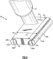
- Figure 4 illustrates an example tool 62 that may be used for finishing operations in the slot 59.
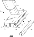
- the example tool 62 includes a head 65 and one or more pads 63A, 63B removably bonded to the head 65 with an adhesive 64.
- Example adhesives 64 may include acrylics, silicones, epoxies, urethanes, and/or imides.
- a handle 67 may extend from the head 65 for a user to engage to maneuver the tool 62 within a slot 59.
- the head 65 includes a groove 66A to receive the pad 63A, which is in the shape of an elongated cylindrical rod and removably bonded to the groove 66A by an adhesive. As will be explained below, other shapes are contemplated within the scope of this disclosure.
- the groove 66A is rounded to accommodate the cylindrical shape of the pad 63A.
- the second pad 63B is substantially similar to the first pad 63A and removably bonded to a groove 66B by an adhesive opposite the head 65 from the pad 63A and groove 66A.
- the example pads 63A, 63B and their respective grooves 66A, 66B are each elongated in a first direction 70 and are opposite the head 65 from one another in a second direction 72 substantially perpendicular to the first direction 70.
- the grooves 66A, 66B are convex, and the pads 63A, 63B provide concave curved outward facing surfaces 69A, 69B.
- the pads 63A, 63B may be made of abrasives, rubbers, or sponges.
- the pads 63A, 63B are made of a silicone carbide filled rubber.
- the handle 67 extends from an upper surface 74 of the head 65.
- the handle 67 and the head 65 are monolithic.
- the handle 67 and the head 65 are formed by a 3D printing process, but other manufacturing processes are also contemplated.
- the handle 67 and head 65 are formed of plastic material, which may include acrylics, epoxies, nylons, imides, polyethylenes, polypropylenes, styrenes, carbonates and/or polyesters.
- the handle 67 and head 65 may be formed by filled plastics. Filler examples may include carbon, nanotubes, glass, and/or ceramic.
- the pads 63A, 63B are fixed to the head 65 strongly enough to perform finishing operations, while still being easily removed from the head 65 when replacement of the pads 63A, 63B is desired. That is, the adhesive provides a high enough shear strength for finishing operations to be performed and a low enough peel strength for removal of the pads 63A, 63B when replacement is desired.
- any one or both of the pads 63A, 63B may be replaced one or multiple times, with the head 65 and handle 67 being reused after pad replacement. As shown, a used pad 63U has been removed and replaced. Efficiency and cost savings is achieved by reuse of the head 65 and handle 67, which may be relatively expensive to manufacture. Moreover, by adhering the pads 63A, 63B to the head 65, the tool 62 may be assembled free of any fasteners, including metal fasteners, avoiding metal on metal contact with the slots 59.
- Figure 6 illustrates a side view of the tool 62.
- the handle 67 extends from the upper surface 74 of the head 65 along a central axis 76 of the handle, which forms an angle 78 with the upper surface 74.
- the angle 78 is less than 90 degrees. In other examples, the angle 78 is 90 degrees.
- Figures 7A and 7B illustrate the example tool 62 applied to a slot 59 in a fan hub 60 for finishing.
- the slot 59 extends axially from a first axial end 80 of the hub 60 to a second axial end 82 opposite the first axial end 80.
- the tool 62 may be inserted into the slot 59 at one of the axial ends 80, 82, and moved along the slot 59 in the direction 84 for finishing the slot 59.
- the direction 84 is substantially parallel to the engine central longitudinal axis (see Figure 1 ). That is, the direction 84 may be in the forward and/or aft directions.
- the direction 84 is also substantially parallel to the direction 70 of elongation of the pads 63A, 63B (see Figure 3 ).
- the tool 62 is configured to finish channels 86A, 86B at opposed circumferential edges of the slot 59 and extending axially along the length of the slot 59.
- Figure 7B shows a cross section of the head 65 and pads 63A, 63B within the slot 59.
- the pads 63A, 63B are received against the rounded channels 86A, 86B circumferentially opposite one another at the radially inner end 88 of the slot 59.
- the pads 63A, 63B are positioned to finish the respective channels 86A, 86B as the tool 62 moves along the slot 59.
- the friction of the pads 63A, 63B against the surface of the slot 59 at the channels 86A, 86B can polish and remove grease and/or debris. In some examples, other tools may be used to finish other areas of the slot 59.
- the example head 65 includes the upper surface 74, the grooves 66A, 66B, a lower surface 90 opposite the head 65 from the upper surface 74, and side surfaces 92 and 94.
- the lower surface 90 extends from the groove 66A to the groove 66B.
- the side surface 92 extends from the groove 66A to the upper surface 74.
- the side surface 94 opposite the head 65 from the side surface 92 extends from the groove 66B to the upper surface 74.
- the upper surface 74 and the lower surface 90 are substantially parallel.
- a surface 96 of the slot 59 extends circumferentially from the channel 86A to the channel 86B and is elevated radially outward relative to the channels 86A, 86B.
- the lower surface 90 of the tool 62 is raised relative to the lowermost points of the pads 63A, 63B to provide a contour to match the slot 59.
- the portions of the head 65 that provide surfaces 92 and 94 are above the pads 63A, 63B when in use to allow a downward force to compress the pads 63A, 63B for finishing.
- the tool 62 may be configured to finish the surface 96, such as by providing a pad at the surface 90 of the tool 62.
- non-destructive inspection may be performed on the slot 59.
- one example of non-destructive inspection is eddy current testing, a known method for testing for fatigue or cracks in metal in gas turbine engine components in which a probe 97 uses electromagnetic induction to detect flaws.
- the tool 62 (not shown) provides a smooth surface in and removes debris and/or grease from the slot 59 prior to eddy current testing. The smooth surface and lack of debris and/or grease provides for improved accuracy in the eddy current measurements.
- the eddy current testing is performed on an area that was finished by the pads 63A, 63B, such as the channels 86A, 86B ( Figures 7A & 7B ).
- FIG. 9 schematically illustrates a portion of another example tool 162.
- a substantially flat pad 163 may be removably bonded via an adhesive 164 to a convex curved surface 166 of the tool 162, such that the pad 163 provides a convex curved outward facing surface 169.
- One of ordinary skill in the art having the benefit of this disclosure would recognize that other geometries could be used to provide curved outward facing surfaces.
- Figure 10 illustrates a flowchart of a method 200 of inspection of a gas turbine engine component.
- a tool 62/162 is applied to a slot 59.
- non-destructive inspection is performed on the slot 59.
- Figure 11 illustrates a flowchart of an example method 300 of finishing a slot 59 in a gas turbine engine.
- a blade may be removed from the slot 59.
- the tool 62/162 is inserted into to the slot 59.
- the method may include removing debris and/or grease from the slot 59 with the tool 62/162.
- the method may include polishing the slot 59 with the tool 62/162.
- the method may include removing a previous pad 63A, 63B from the head 65 and replacing the previous pad 63A, 63B with a new pad. Pads 63A, 63B may be replaced before or after the tool 62/162 is applied to a slot 59.
- Figure 12 illustrates a flowchart of a method 400 of manufacturing a tool for finishing a slot in a gas turbine engine.
- a head 65 and a handle 67 extending from the head 65 are provided. This step may include 3D printing the handle 67 and the head 65 in some examples.
- an adhesive is applied to the head 65.
- a pad 63A, 63B is bonded to the head 65 with the adhesive.
- the method includes applying the adhesive to a groove in the head 65 and bonding the pad 63A, 63B to the groove.
- the method includes mechanically affixing the pad to the head 65 while the adhesive cures and removing mechanical means after cure is complete.
Landscapes
- Engineering & Computer Science (AREA)
- Mechanical Engineering (AREA)
- General Engineering & Computer Science (AREA)
- Structures Of Non-Positive Displacement Pumps (AREA)
- Standing Axle, Rod, Or Tube Structures Coupled By Welding, Adhesion, Or Deposition (AREA)
- Polishing Bodies And Polishing Tools (AREA)
Priority Applications (1)
| Application Number | Priority Date | Filing Date | Title |
|---|---|---|---|
| EP23152732.6A EP4186640A1 (de) | 2018-09-05 | 2019-09-05 | Gasturbinenmotorschlitzwerkzeuge |
Applications Claiming Priority (1)
| Application Number | Priority Date | Filing Date | Title |
|---|---|---|---|
| US16/121,856 US11085323B2 (en) | 2018-09-05 | 2018-09-05 | Gas turbine engine slot tools |
Related Child Applications (2)
| Application Number | Title | Priority Date | Filing Date |
|---|---|---|---|
| EP23152732.6A Division-Into EP4186640A1 (de) | 2018-09-05 | 2019-09-05 | Gasturbinenmotorschlitzwerkzeuge |
| EP23152732.6A Division EP4186640A1 (de) | 2018-09-05 | 2019-09-05 | Gasturbinenmotorschlitzwerkzeuge |
Publications (3)
| Publication Number | Publication Date |
|---|---|
| EP3628443A2 true EP3628443A2 (de) | 2020-04-01 |
| EP3628443A3 EP3628443A3 (de) | 2020-07-29 |
| EP3628443B1 EP3628443B1 (de) | 2023-03-08 |
Family
ID=67874312
Family Applications (2)
| Application Number | Title | Priority Date | Filing Date |
|---|---|---|---|
| EP19195566.5A Active EP3628443B1 (de) | 2018-09-05 | 2019-09-05 | Gasturbinenmotorschlitzwerkzeuge |
| EP23152732.6A Pending EP4186640A1 (de) | 2018-09-05 | 2019-09-05 | Gasturbinenmotorschlitzwerkzeuge |
Family Applications After (1)
| Application Number | Title | Priority Date | Filing Date |
|---|---|---|---|
| EP23152732.6A Pending EP4186640A1 (de) | 2018-09-05 | 2019-09-05 | Gasturbinenmotorschlitzwerkzeuge |
Country Status (2)
| Country | Link |
|---|---|
| US (1) | US11085323B2 (de) |
| EP (2) | EP3628443B1 (de) |
Families Citing this family (2)
| Publication number | Priority date | Publication date | Assignee | Title |
|---|---|---|---|---|
| CN112264359B (zh) * | 2020-09-23 | 2021-11-23 | 万秀芬 | 一种钢板表面油污清洁设备 |
| GB202116563D0 (en) * | 2021-11-17 | 2021-12-29 | Rolls Royce Plc | Spline cleaning device |
Family Cites Families (15)
| Publication number | Priority date | Publication date | Assignee | Title |
|---|---|---|---|---|
| US4570278A (en) * | 1983-02-25 | 1986-02-18 | The Kartridg Pak Co. | Portable polisher and buffs therefor |
| GB0324704D0 (en) * | 2003-10-23 | 2003-11-26 | Rolls Royce Plc | An apparatus and a method of applying a dry film lubricant to a rotor slot |
| US7412741B2 (en) * | 2004-10-18 | 2008-08-19 | General Electric Company | Apparatus and methods for cleaning cooling slot surfaces on a rotor wheel of a gas turbine |
| FR2886179B1 (fr) | 2005-05-27 | 2009-01-02 | Snecma Moteurs Sa | Procede et dispositif d'usinage d'une rainure en pheripherie d'une piece telle qu'un disque de rotor d'une turbomachine |
| US20100144257A1 (en) * | 2008-12-05 | 2010-06-10 | Bart Donald Beaumont | Abrasive pad releasably attachable to cleaning devices |
| US8157620B2 (en) * | 2008-12-23 | 2012-04-17 | General Electric Company | System and method for cleaning stator slots |
| US8631535B2 (en) * | 2009-08-26 | 2014-01-21 | Brian Phillips | Articulated, multiple cleaning surface cleaning tool and method |
| US20110294407A1 (en) | 2010-05-28 | 2011-12-01 | Justin Wade Doyle | Manual operated detail sander |
| US8813294B2 (en) | 2010-07-07 | 2014-08-26 | Clean & Go, Llc | Grout and tile cleaning implement with replaceable member |
| US8876577B2 (en) * | 2010-11-09 | 2014-11-04 | Karcher North America, Inc. | Floor finish removal and cleaning apparatus |
| US8209812B1 (en) * | 2011-02-21 | 2012-07-03 | King Fahd University Of Petroleum And Minerals | Grill cleaning brush |
| US20130185877A1 (en) | 2012-01-25 | 2013-07-25 | General Electric Company | Apparatus for cleaning a slot |
| US20140150815A1 (en) * | 2012-11-30 | 2014-06-05 | Applied Materials, Inc. | Disc-brush holder apparatus, disc-brush assembly, and substrate processing methods |
| US10385724B2 (en) * | 2017-03-28 | 2019-08-20 | General Electric Company | Tools and methods for cleaning grooves of a turbine rotor disc |
| DE102017208949A1 (de) | 2017-05-29 | 2018-11-29 | Siemens Aktiengesellschaft | Verfahren zum Reinigen einer Schaufelfußaufnahmenut |
-
2018
- 2018-09-05 US US16/121,856 patent/US11085323B2/en active Active
-
2019
- 2019-09-05 EP EP19195566.5A patent/EP3628443B1/de active Active
- 2019-09-05 EP EP23152732.6A patent/EP4186640A1/de active Pending
Also Published As
| Publication number | Publication date |
|---|---|
| US20200072077A1 (en) | 2020-03-05 |
| EP3628443B1 (de) | 2023-03-08 |
| EP4186640A1 (de) | 2023-05-31 |
| EP3628443A3 (de) | 2020-07-29 |
| US11085323B2 (en) | 2021-08-10 |
Similar Documents
| Publication | Publication Date | Title |
|---|---|---|
| US6302625B1 (en) | Method and apparatus for refurbishing a gas turbine airfoil | |
| US8157620B2 (en) | System and method for cleaning stator slots | |
| EP2588266B1 (de) | Herstellung und reparatur einer turbinenschaufel durch widerstandschweissen in fester phase | |
| US4873751A (en) | Fabrication or repair technique for integrally bladed rotor assembly | |
| US6666653B1 (en) | Inertia welding of blades to rotors | |
| US7980813B2 (en) | Fan outlet guide vane shroud insert repair | |
| EP3382162B1 (de) | Werkzeuge und verfahren zur reinigung der nuten einer turbinenrotorscheibe | |
| EP3628443B1 (de) | Gasturbinenmotorschlitzwerkzeuge | |
| JP2013193205A (ja) | コンポーネントを修理する方法、コンポーネントの修理工具およびコンポーネント | |
| JPH11247613A (ja) | 翼型保護面のシールド方法およびその装置 | |
| JP7370688B2 (ja) | 表面処理ツールおよび、ターボ機械の表面処理方法 | |
| EP2050927A2 (de) | Verfahren zum Wiederherstellen der Tragflächenspitzenkontur | |
| JPH11343562A (ja) | 溶射コーティング方法 | |
| CN106994636A (zh) | 涡轮机的表面处理 | |
| US10662808B2 (en) | Apparatus for cleaning a slot | |
| CN105773057A (zh) | 一种轴承座轴孔的修复工艺 | |
| US6202273B1 (en) | Shim removing tool | |
| US20060156544A1 (en) | Method and apparatus to remove material from a turbine wheel in-situ | |
| CN106670721A (zh) | 起动机涡轮叶轮的深度修理方法 | |
| CN114867929A (zh) | 用于加工风扇叶片的装置和方法 | |
| CN107687445B (zh) | 叶轮组件、改变叶轮的方法和将叶片安装至叶轮的方法 | |
| US8127442B2 (en) | Compressor blade flow form technique for repair | |
| US10821575B2 (en) | Clamp assembly and method | |
| US20100095505A1 (en) | Method of replacing a damaged bonded stud on a composite bypass duct | |
| US20200269365A1 (en) | Method for machining or inspecting a blade |
Legal Events
| Date | Code | Title | Description |
|---|---|---|---|
| PUAI | Public reference made under article 153(3) epc to a published international application that has entered the european phase |
Free format text: ORIGINAL CODE: 0009012 |
|
| STAA | Information on the status of an ep patent application or granted ep patent |
Free format text: STATUS: THE APPLICATION HAS BEEN PUBLISHED |
|
| AK | Designated contracting states |
Kind code of ref document: A2 Designated state(s): AL AT BE BG CH CY CZ DE DK EE ES FI FR GB GR HR HU IE IS IT LI LT LU LV MC MK MT NL NO PL PT RO RS SE SI SK SM TR |
|
| AX | Request for extension of the european patent |
Extension state: BA ME |
|
| RIN1 | Information on inventor provided before grant (corrected) |
Inventor name: CAMPAGNA, NATHAN C. Inventor name: HARNER, JOHN |
|
| PUAL | Search report despatched |
Free format text: ORIGINAL CODE: 0009013 |
|
| STAA | Information on the status of an ep patent application or granted ep patent |
Free format text: STATUS: REQUEST FOR EXAMINATION WAS MADE |
|
| AK | Designated contracting states |
Kind code of ref document: A3 Designated state(s): AL AT BE BG CH CY CZ DE DK EE ES FI FR GB GR HR HU IE IS IT LI LT LU LV MC MK MT NL NO PL PT RO RS SE SI SK SM TR |
|
| AX | Request for extension of the european patent |
Extension state: BA ME |
|
| RIC1 | Information provided on ipc code assigned before grant |
Ipc: B24D 15/02 20060101AFI20200623BHEP Ipc: F01D 5/30 20060101ALI20200623BHEP |
|
| 17P | Request for examination filed |
Effective date: 20200722 |
|
| RBV | Designated contracting states (corrected) |
Designated state(s): AL AT BE BG CH CY CZ DE DK EE ES FI FR GB GR HR HU IE IS IT LI LT LU LV MC MK MT NL NO PL PT RO RS SE SI SK SM TR |
|
| STAA | Information on the status of an ep patent application or granted ep patent |
Free format text: STATUS: EXAMINATION IS IN PROGRESS |
|
| 17Q | First examination report despatched |
Effective date: 20201124 |
|
| RAP1 | Party data changed (applicant data changed or rights of an application transferred) |
Owner name: RAYTHEON TECHNOLOGIES CORPORATION |
|
| REG | Reference to a national code |
Ref country code: DE Ref legal event code: R079 Free format text: PREVIOUS MAIN CLASS: B24D0015020000 Ipc: F01D0021000000 Ref country code: DE Ref legal event code: R079 Ref document number: 602019026091 Country of ref document: DE Free format text: PREVIOUS MAIN CLASS: B24D0015020000 Ipc: F01D0021000000 |
|
| GRAP | Despatch of communication of intention to grant a patent |
Free format text: ORIGINAL CODE: EPIDOSNIGR1 |
|
| STAA | Information on the status of an ep patent application or granted ep patent |
Free format text: STATUS: GRANT OF PATENT IS INTENDED |
|
| RIC1 | Information provided on ipc code assigned before grant |
Ipc: F01D 5/30 20060101ALI20220825BHEP Ipc: B24D 15/02 20060101ALI20220825BHEP Ipc: F01D 25/00 20060101ALI20220825BHEP Ipc: F01D 21/00 20060101AFI20220825BHEP |
|
| INTG | Intention to grant announced |
Effective date: 20220919 |
|
| GRAS | Grant fee paid |
Free format text: ORIGINAL CODE: EPIDOSNIGR3 |
|
| GRAA | (expected) grant |
Free format text: ORIGINAL CODE: 0009210 |
|
| STAA | Information on the status of an ep patent application or granted ep patent |
Free format text: STATUS: THE PATENT HAS BEEN GRANTED |
|
| AK | Designated contracting states |
Kind code of ref document: B1 Designated state(s): AL AT BE BG CH CY CZ DE DK EE ES FI FR GB GR HR HU IE IS IT LI LT LU LV MC MK MT NL NO PL PT RO RS SE SI SK SM TR |
|
| REG | Reference to a national code |
Ref country code: CH Ref legal event code: EP Ref country code: AT Ref legal event code: REF Ref document number: 1552698 Country of ref document: AT Kind code of ref document: T Effective date: 20230315 |
|
| REG | Reference to a national code |
Ref country code: IE Ref legal event code: FG4D |
|
| REG | Reference to a national code |
Ref country code: DE Ref legal event code: R096 Ref document number: 602019026091 Country of ref document: DE |
|
| REG | Reference to a national code |
Ref country code: LT Ref legal event code: MG9D |
|
| P01 | Opt-out of the competence of the unified patent court (upc) registered |
Effective date: 20230521 |
|
| REG | Reference to a national code |
Ref country code: NL Ref legal event code: MP Effective date: 20230308 |
|
| PG25 | Lapsed in a contracting state [announced via postgrant information from national office to epo] |
Ref country code: RS Free format text: LAPSE BECAUSE OF FAILURE TO SUBMIT A TRANSLATION OF THE DESCRIPTION OR TO PAY THE FEE WITHIN THE PRESCRIBED TIME-LIMIT Effective date: 20230308 Ref country code: NO Free format text: LAPSE BECAUSE OF FAILURE TO SUBMIT A TRANSLATION OF THE DESCRIPTION OR TO PAY THE FEE WITHIN THE PRESCRIBED TIME-LIMIT Effective date: 20230608 Ref country code: LV Free format text: LAPSE BECAUSE OF FAILURE TO SUBMIT A TRANSLATION OF THE DESCRIPTION OR TO PAY THE FEE WITHIN THE PRESCRIBED TIME-LIMIT Effective date: 20230308 Ref country code: LT Free format text: LAPSE BECAUSE OF FAILURE TO SUBMIT A TRANSLATION OF THE DESCRIPTION OR TO PAY THE FEE WITHIN THE PRESCRIBED TIME-LIMIT Effective date: 20230308 Ref country code: HR Free format text: LAPSE BECAUSE OF FAILURE TO SUBMIT A TRANSLATION OF THE DESCRIPTION OR TO PAY THE FEE WITHIN THE PRESCRIBED TIME-LIMIT Effective date: 20230308 Ref country code: ES Free format text: LAPSE BECAUSE OF FAILURE TO SUBMIT A TRANSLATION OF THE DESCRIPTION OR TO PAY THE FEE WITHIN THE PRESCRIBED TIME-LIMIT Effective date: 20230308 |
|
| REG | Reference to a national code |
Ref country code: AT Ref legal event code: MK05 Ref document number: 1552698 Country of ref document: AT Kind code of ref document: T Effective date: 20230308 |
|
| PG25 | Lapsed in a contracting state [announced via postgrant information from national office to epo] |
Ref country code: SE Free format text: LAPSE BECAUSE OF FAILURE TO SUBMIT A TRANSLATION OF THE DESCRIPTION OR TO PAY THE FEE WITHIN THE PRESCRIBED TIME-LIMIT Effective date: 20230308 Ref country code: NL Free format text: LAPSE BECAUSE OF FAILURE TO SUBMIT A TRANSLATION OF THE DESCRIPTION OR TO PAY THE FEE WITHIN THE PRESCRIBED TIME-LIMIT Effective date: 20230308 Ref country code: GR Free format text: LAPSE BECAUSE OF FAILURE TO SUBMIT A TRANSLATION OF THE DESCRIPTION OR TO PAY THE FEE WITHIN THE PRESCRIBED TIME-LIMIT Effective date: 20230609 Ref country code: FI Free format text: LAPSE BECAUSE OF FAILURE TO SUBMIT A TRANSLATION OF THE DESCRIPTION OR TO PAY THE FEE WITHIN THE PRESCRIBED TIME-LIMIT Effective date: 20230308 |
|
| PG25 | Lapsed in a contracting state [announced via postgrant information from national office to epo] |
Ref country code: SM Free format text: LAPSE BECAUSE OF FAILURE TO SUBMIT A TRANSLATION OF THE DESCRIPTION OR TO PAY THE FEE WITHIN THE PRESCRIBED TIME-LIMIT Effective date: 20230308 Ref country code: RO Free format text: LAPSE BECAUSE OF FAILURE TO SUBMIT A TRANSLATION OF THE DESCRIPTION OR TO PAY THE FEE WITHIN THE PRESCRIBED TIME-LIMIT Effective date: 20230308 Ref country code: PT Free format text: LAPSE BECAUSE OF FAILURE TO SUBMIT A TRANSLATION OF THE DESCRIPTION OR TO PAY THE FEE WITHIN THE PRESCRIBED TIME-LIMIT Effective date: 20230710 Ref country code: EE Free format text: LAPSE BECAUSE OF FAILURE TO SUBMIT A TRANSLATION OF THE DESCRIPTION OR TO PAY THE FEE WITHIN THE PRESCRIBED TIME-LIMIT Effective date: 20230308 Ref country code: CZ Free format text: LAPSE BECAUSE OF FAILURE TO SUBMIT A TRANSLATION OF THE DESCRIPTION OR TO PAY THE FEE WITHIN THE PRESCRIBED TIME-LIMIT Effective date: 20230308 Ref country code: AT Free format text: LAPSE BECAUSE OF FAILURE TO SUBMIT A TRANSLATION OF THE DESCRIPTION OR TO PAY THE FEE WITHIN THE PRESCRIBED TIME-LIMIT Effective date: 20230308 |
|
| RAP4 | Party data changed (patent owner data changed or rights of a patent transferred) |
Owner name: RTX CORPORATION |
|
| PG25 | Lapsed in a contracting state [announced via postgrant information from national office to epo] |
Ref country code: SK Free format text: LAPSE BECAUSE OF FAILURE TO SUBMIT A TRANSLATION OF THE DESCRIPTION OR TO PAY THE FEE WITHIN THE PRESCRIBED TIME-LIMIT Effective date: 20230308 Ref country code: PL Free format text: LAPSE BECAUSE OF FAILURE TO SUBMIT A TRANSLATION OF THE DESCRIPTION OR TO PAY THE FEE WITHIN THE PRESCRIBED TIME-LIMIT Effective date: 20230308 Ref country code: IS Free format text: LAPSE BECAUSE OF FAILURE TO SUBMIT A TRANSLATION OF THE DESCRIPTION OR TO PAY THE FEE WITHIN THE PRESCRIBED TIME-LIMIT Effective date: 20230708 |
|
| REG | Reference to a national code |
Ref country code: DE Ref legal event code: R097 Ref document number: 602019026091 Country of ref document: DE |
|
| PLBE | No opposition filed within time limit |
Free format text: ORIGINAL CODE: 0009261 |
|
| STAA | Information on the status of an ep patent application or granted ep patent |
Free format text: STATUS: NO OPPOSITION FILED WITHIN TIME LIMIT |
|
| PG25 | Lapsed in a contracting state [announced via postgrant information from national office to epo] |
Ref country code: SI Free format text: LAPSE BECAUSE OF FAILURE TO SUBMIT A TRANSLATION OF THE DESCRIPTION OR TO PAY THE FEE WITHIN THE PRESCRIBED TIME-LIMIT Effective date: 20230308 Ref country code: DK Free format text: LAPSE BECAUSE OF FAILURE TO SUBMIT A TRANSLATION OF THE DESCRIPTION OR TO PAY THE FEE WITHIN THE PRESCRIBED TIME-LIMIT Effective date: 20230308 |
|
| 26N | No opposition filed |
Effective date: 20231211 |
|
| REG | Reference to a national code |
Ref country code: CH Ref legal event code: PL |
|
| PG25 | Lapsed in a contracting state [announced via postgrant information from national office to epo] |
Ref country code: LU Free format text: LAPSE BECAUSE OF NON-PAYMENT OF DUE FEES Effective date: 20230905 |
|
| REG | Reference to a national code |
Ref country code: BE Ref legal event code: MM Effective date: 20230930 |
|
| PG25 | Lapsed in a contracting state [announced via postgrant information from national office to epo] |
Ref country code: LU Free format text: LAPSE BECAUSE OF NON-PAYMENT OF DUE FEES Effective date: 20230905 Ref country code: IT Free format text: LAPSE BECAUSE OF FAILURE TO SUBMIT A TRANSLATION OF THE DESCRIPTION OR TO PAY THE FEE WITHIN THE PRESCRIBED TIME-LIMIT Effective date: 20230308 Ref country code: MC Free format text: LAPSE BECAUSE OF FAILURE TO SUBMIT A TRANSLATION OF THE DESCRIPTION OR TO PAY THE FEE WITHIN THE PRESCRIBED TIME-LIMIT Effective date: 20230308 |
|
| REG | Reference to a national code |
Ref country code: IE Ref legal event code: MM4A |
|
| PG25 | Lapsed in a contracting state [announced via postgrant information from national office to epo] |
Ref country code: IE Free format text: LAPSE BECAUSE OF NON-PAYMENT OF DUE FEES Effective date: 20230905 |
|
| PG25 | Lapsed in a contracting state [announced via postgrant information from national office to epo] |
Ref country code: CH Free format text: LAPSE BECAUSE OF NON-PAYMENT OF DUE FEES Effective date: 20230930 |
|
| PG25 | Lapsed in a contracting state [announced via postgrant information from national office to epo] |
Ref country code: IE Free format text: LAPSE BECAUSE OF NON-PAYMENT OF DUE FEES Effective date: 20230905 Ref country code: CH Free format text: LAPSE BECAUSE OF NON-PAYMENT OF DUE FEES Effective date: 20230930 |
|
| PG25 | Lapsed in a contracting state [announced via postgrant information from national office to epo] |
Ref country code: BE Free format text: LAPSE BECAUSE OF NON-PAYMENT OF DUE FEES Effective date: 20230930 |
|
| PG25 | Lapsed in a contracting state [announced via postgrant information from national office to epo] |
Ref country code: BG Free format text: LAPSE BECAUSE OF FAILURE TO SUBMIT A TRANSLATION OF THE DESCRIPTION OR TO PAY THE FEE WITHIN THE PRESCRIBED TIME-LIMIT Effective date: 20230308 |
|
| PG25 | Lapsed in a contracting state [announced via postgrant information from national office to epo] |
Ref country code: BG Free format text: LAPSE BECAUSE OF FAILURE TO SUBMIT A TRANSLATION OF THE DESCRIPTION OR TO PAY THE FEE WITHIN THE PRESCRIBED TIME-LIMIT Effective date: 20230308 |
|
| PG25 | Lapsed in a contracting state [announced via postgrant information from national office to epo] |
Ref country code: CY Free format text: LAPSE BECAUSE OF FAILURE TO SUBMIT A TRANSLATION OF THE DESCRIPTION OR TO PAY THE FEE WITHIN THE PRESCRIBED TIME-LIMIT; INVALID AB INITIO Effective date: 20190905 |
|
| PG25 | Lapsed in a contracting state [announced via postgrant information from national office to epo] |
Ref country code: HU Free format text: LAPSE BECAUSE OF FAILURE TO SUBMIT A TRANSLATION OF THE DESCRIPTION OR TO PAY THE FEE WITHIN THE PRESCRIBED TIME-LIMIT; INVALID AB INITIO Effective date: 20190905 |
|
| REG | Reference to a national code |
Ref country code: DE Ref legal event code: R081 Ref document number: 602019026091 Country of ref document: DE Owner name: RTX CORPORATION (N.D.GES.D. STAATES DELAWARE),, US Free format text: FORMER OWNER: RAYTHEON TECHNOLOGIES CORPORATION, FARMINGTON, CT, US |
|
| PGFP | Annual fee paid to national office [announced via postgrant information from national office to epo] |
Ref country code: DE Payment date: 20250820 Year of fee payment: 7 |
|
| PGFP | Annual fee paid to national office [announced via postgrant information from national office to epo] |
Ref country code: GB Payment date: 20250822 Year of fee payment: 7 |
|
| PGFP | Annual fee paid to national office [announced via postgrant information from national office to epo] |
Ref country code: FR Payment date: 20250820 Year of fee payment: 7 |
|
| PG25 | Lapsed in a contracting state [announced via postgrant information from national office to epo] |
Ref country code: TR Free format text: LAPSE BECAUSE OF FAILURE TO SUBMIT A TRANSLATION OF THE DESCRIPTION OR TO PAY THE FEE WITHIN THE PRESCRIBED TIME-LIMIT Effective date: 20230308 |