EP3628409A1 - Water outflow device capable of self-cleaning and water outflow device capable of varying water flow - Google Patents
Water outflow device capable of self-cleaning and water outflow device capable of varying water flow Download PDFInfo
- Publication number
- EP3628409A1 EP3628409A1 EP18795145.4A EP18795145A EP3628409A1 EP 3628409 A1 EP3628409 A1 EP 3628409A1 EP 18795145 A EP18795145 A EP 18795145A EP 3628409 A1 EP3628409 A1 EP 3628409A1
- Authority
- EP
- European Patent Office
- Prior art keywords
- water
- water outlet
- axial direction
- disposed
- needle plate
- Prior art date
- Legal status (The legal status is an assumption and is not a legal conclusion. Google has not performed a legal analysis and makes no representation as to the accuracy of the status listed.)
- Granted
Links
Images




Classifications
-
- B—PERFORMING OPERATIONS; TRANSPORTING
- B05—SPRAYING OR ATOMISING IN GENERAL; APPLYING FLUENT MATERIALS TO SURFACES, IN GENERAL
- B05B—SPRAYING APPARATUS; ATOMISING APPARATUS; NOZZLES
- B05B1/00—Nozzles, spray heads or other outlets, with or without auxiliary devices such as valves, heating means
- B05B1/14—Nozzles, spray heads or other outlets, with or without auxiliary devices such as valves, heating means with multiple outlet openings; with strainers in or outside the outlet opening
- B05B1/18—Roses; Shower heads
-
- B—PERFORMING OPERATIONS; TRANSPORTING
- B05—SPRAYING OR ATOMISING IN GENERAL; APPLYING FLUENT MATERIALS TO SURFACES, IN GENERAL
- B05B—SPRAYING APPARATUS; ATOMISING APPARATUS; NOZZLES
- B05B1/00—Nozzles, spray heads or other outlets, with or without auxiliary devices such as valves, heating means
- B05B1/02—Nozzles, spray heads or other outlets, with or without auxiliary devices such as valves, heating means designed to produce a jet, spray, or other discharge of particular shape or nature, e.g. in single drops, or having an outlet of particular shape
- B05B1/08—Nozzles, spray heads or other outlets, with or without auxiliary devices such as valves, heating means designed to produce a jet, spray, or other discharge of particular shape or nature, e.g. in single drops, or having an outlet of particular shape of pulsating nature, e.g. delivering liquid in successive separate quantities
- B05B1/083—Nozzles, spray heads or other outlets, with or without auxiliary devices such as valves, heating means designed to produce a jet, spray, or other discharge of particular shape or nature, e.g. in single drops, or having an outlet of particular shape of pulsating nature, e.g. delivering liquid in successive separate quantities the pulsating mechanism comprising movable parts
-
- B—PERFORMING OPERATIONS; TRANSPORTING
- B05—SPRAYING OR ATOMISING IN GENERAL; APPLYING FLUENT MATERIALS TO SURFACES, IN GENERAL
- B05B—SPRAYING APPARATUS; ATOMISING APPARATUS; NOZZLES
- B05B15/00—Details of spraying plant or spraying apparatus not otherwise provided for; Accessories
- B05B15/50—Arrangements for cleaning; Arrangements for preventing deposits, drying-out or blockage; Arrangements for detecting improper discharge caused by the presence of foreign matter
- B05B15/52—Arrangements for cleaning; Arrangements for preventing deposits, drying-out or blockage; Arrangements for detecting improper discharge caused by the presence of foreign matter for removal of clogging particles
- B05B15/522—Arrangements for cleaning; Arrangements for preventing deposits, drying-out or blockage; Arrangements for detecting improper discharge caused by the presence of foreign matter for removal of clogging particles using cleaning elements penetrating the discharge openings
- B05B15/5223—Arrangements for cleaning; Arrangements for preventing deposits, drying-out or blockage; Arrangements for detecting improper discharge caused by the presence of foreign matter for removal of clogging particles using cleaning elements penetrating the discharge openings the cleaning element, e.g. a needle, and the discharge opening being movable relative to each other in a direction substantially parallel to the flow of liquid or other fluent material through said opening
- B05B15/5225—Arrangements for cleaning; Arrangements for preventing deposits, drying-out or blockage; Arrangements for detecting improper discharge caused by the presence of foreign matter for removal of clogging particles using cleaning elements penetrating the discharge openings the cleaning element, e.g. a needle, and the discharge opening being movable relative to each other in a direction substantially parallel to the flow of liquid or other fluent material through said opening the cleaning element being located upstream of the discharge opening or being actuated upstream therefrom
-
- B—PERFORMING OPERATIONS; TRANSPORTING
- B05—SPRAYING OR ATOMISING IN GENERAL; APPLYING FLUENT MATERIALS TO SURFACES, IN GENERAL
- B05B—SPRAYING APPARATUS; ATOMISING APPARATUS; NOZZLES
- B05B1/00—Nozzles, spray heads or other outlets, with or without auxiliary devices such as valves, heating means
- B05B1/02—Nozzles, spray heads or other outlets, with or without auxiliary devices such as valves, heating means designed to produce a jet, spray, or other discharge of particular shape or nature, e.g. in single drops, or having an outlet of particular shape
- B05B1/08—Nozzles, spray heads or other outlets, with or without auxiliary devices such as valves, heating means designed to produce a jet, spray, or other discharge of particular shape or nature, e.g. in single drops, or having an outlet of particular shape of pulsating nature, e.g. delivering liquid in successive separate quantities
- B05B1/083—Nozzles, spray heads or other outlets, with or without auxiliary devices such as valves, heating means designed to produce a jet, spray, or other discharge of particular shape or nature, e.g. in single drops, or having an outlet of particular shape of pulsating nature, e.g. delivering liquid in successive separate quantities the pulsating mechanism comprising movable parts
- B05B1/085—Nozzles, spray heads or other outlets, with or without auxiliary devices such as valves, heating means designed to produce a jet, spray, or other discharge of particular shape or nature, e.g. in single drops, or having an outlet of particular shape of pulsating nature, e.g. delivering liquid in successive separate quantities the pulsating mechanism comprising movable parts rotated by the liquid or other fluent material discharged, e.g. liquid rotated turbines
Definitions
- the deposit removal needle plate comprises a plurality of needles, and the deposit removal needle plate is swingably connected to the rotatable member;
Landscapes
- Nozzles (AREA)
- Domestic Plumbing Installations (AREA)
Abstract
Description
- The present disclosure relates to a water outlet device.
- The shower head is a kind of shower device that is commonly used in daily life. When the shower head is used for a long time or in a place with poor water quality, sediment attached to an inner wall of a water outlet hole on a water outlet surface of the shower head. Overtime, the sediment will accumulate and block the water outlet hole, causing the shower head to not work properly. For this reason, there are many shower heads with a descaling function on the market. Generally, a descaling plate with a plurality of descaling needles disposed on a bottom surface of the descaling plate is movably arranged in the shower head, and descaling is driven manually or by flowing water. In the existing descaling products, the descaling plate moves in the axial direction. In order to ensure smooth movement of the descaling plate, a gap of a certain size must be left between the descaling needles and the inner wall of the water outlet hole, otherwise the descaling plate will not move normally because of friction between the descaling needles and the inner wall of the water outlet hole. However, if there is a gap between the descaling needles and the inner wall of the water outlet hole, sediment attached to the inner wall of the water outlet hole cannot be completely removed, which causes the exiting water to be redirected and the purpose of cleaning the sediment cannot be achieved.
- The present disclosure provides a self-cleaning water outlet device to solve deficiencies of the existing techniques. During the water discharge process, the needles swing about an axial direction in water outlet holes of a water outlet cover, so that the sediment attached to the inner walls of the water outlet holes is automatically removed.
- In order to solve the aforementioned technical problems, the present disclosure provides a self-cleaning water outlet device, which comprises a body, a deposit removal needle plate disposed in the body, and a rotatable member driven to rotate about an axial direction by flowing water;
- An axial direction of the deposit removal needle plate and an axial direction of the water outlet cover are coaxial. The deposit removal needle plate comprises a plurality of needles, and the deposit removal needle plate is swingably connected to the rotatable member;
- When water flows into the water outlet device, the water drives the rotatable member to rotate, the rotatable member drives each of the plurality of needles to swing about the axial direction in a corresponding one of the plurality of water outlet holes of the water outlet cover, and each of the plurality of needles rubs against sediment deposited on an inner wall of the corresponding one of the plurality of water outlet holes while each of the plurality of needles are swinging to dislodge the sediment of the inner wall of the corresponding one of the plurality of water outlet holes.
- In a preferred embodiment, the body comprises an oblique water body, and the oblique water body comprises a chamber. A first end of the chamber is disposed with a water inlet in an axial direction, and a sidewall of the chamber is disposed with a plurality of oblique water outlets arranged along a circumferential direction.
- In a preferred embodiment, the rotatable member is an impeller disposed outside of the sidewall of the chamber of the oblique water body, and the water flows into the impeller from the plurality of oblique water outlets. Blades of the impeller are impacted to drive the impeller to rotate by the water.
- In a preferred embodiment, a first side of the impeller facing the deposit removal needle plate extends downward in the axial direction to form a cam. A first side of the deposit removal needle plate facing the oblique water body extends upward in the axial direction to form a connecting member. The cam is disposed in the connecting member, and a sidewall of the cam abuts a sidewall of the connecting member to define a swing connection.
- In a preferred embodiment, in the axial direction, the impeller is disposed with at least one water outlet at a lower end of the impeller. The water flows out from the plurality of oblique water outlets, enters into the impeller, flows out from the at least one water outlet, and then flows to the deposit removal needle plate. The deposit removal needle plate is disposed with at least one overflow hole disposed in the axial direction, and the water flows from the at least one overflow hole into the plurality of water outlet holes of the water outlet cover.
- In a preferred embodiment, the self-cleaning water outlet device further comprises a movable member. The movable member is driven by the water and moves in an axial direction. The deposit removal needle plate and the moving member are connected in the axial direction;
When the water flows into the water outlet device, the water flows to drive the movable member to drive the deposit removal needle plate to move downward in the axial direction, and each of the plurality of needles move into the corresponding one of the plurality of water outlet holes. - In a preferred embodiment, in the axial direction, a second end of the chamber away from the water inlet is disposed with a through hole. A first end of the movable member passes through the through hole and abuts the deposit removal needle plate and is linked to the deposit removal needle plate, and a second end of the movable member is disposed in the chamber. When the water flows from the water inlet into the chamber, an impact force generated by the water flowing on the movable member drives the movable member to move downward in the axial direction.
- In a preferred embodiment, in an axial direction, the cam is disposed with a locating hole. The movable member is inserted into the connecting member through the locating hole and abuts, in the axial direction, a bottom end surface of the connecting member.
- In a preferred embodiment, a reset member is disposed between the deposit removal needle plate and the water outlet cover. When the deposit removal needle plate moves downward in the axial direction, the reset member accumulates an elastic reset force.
- In a preferred embodiment, the second end of the movable member disposd in the chamber is a water storage end. When no water flows into the chamber from the water inlet, the reset member drives the deposit removal needle plate to move upward in the axial direction, and the water storage end moves upward, in an axial direction, toward the water inlet.
- The present disclosure further provides a swinging water outlet device, which comprises a body, a flowing water switchable member disposed in the body, and a rotatable member driven to rotate about an axial direction by flowing water;
An axial direction of the flowing water switchable member and an axial direction of the water outlet cover are coaxial. The flowing water switchable member comprises a plurality of switchable units, and the flowing water switchable member is swingably connected to the rotatable member;
When water flows into the swinging water outlet device, the water drives the rotatable member to rotate, the rotatable member drives each of the plurality of switchable units to swing about the axial direction in a corresponding one of the plurality of water outlet holes of the water outlet cover, and a flow direction of the water in each of the plurality of water outlet holes changes due to a swing movement of a corresponding one of the plurality of switchable units. - In a preferred embodiment, the body comprises an oblique water body, and the oblique water body comprises a chamber. In an axial direction, a first end of the chamber is disposed with a water inlet, and a sidewall of the chamber is disposed with a plurality of oblique water outlets arranged along a circumferential direction.
- In a preferred embodiment, the rotatable member is an impeller disposed outside of the sidewall of the chamber of the oblique water body, and the water flows into the impeller from the plurality of oblique water outlets. Blades of the impeller are impacted to drive the impeller to rotate by the water.
- In a preferred embodiment, a first side of the impeller facing the flowing water switchable member extends downward in the axial direction to form a cam. A first side of the flowing water switchable member facing the oblique water body extends upward in the axial direction to form a connecting member. The cam is disposed in the connecting member, and a sidewall of the cam abuts a sidewall of the connecting member to define a swing connection.
- In a preferred embodiment, in the axial direction, the impeller is disposed with at least one water outlet at a lower end of the impeller. The water flows out from the plurality of oblique water outlets, enters into the impeller, flows out from the at least one water outlet, and flows to the flowing water switchable member. The flowing water switchable member is disposed with at least one overflow hole disposed in the axial direction, and the water flows from the at least one overflow hole into the plurality of water outlet holes of the water outlet cover.
- In a preferred embodiment, the swinging water outlet device further comprises a movable member, and the movable member is driven by the water and moves in an axial direction. The flowing water switchable member and the moving member are connected in the axial direction;
When the water flows into the water outlet device, the water flows to drive the movable member to drive the flowing water switchable member to move downward in the axial direction, and each of the plurality of switchable units move into the corresponding one of the plurality of water outlet holes of the water outlet cover. - In a preferred embodiment, in the axial direction, a second end of the chamber away from the water inlet is disposed with a through hole. A first end of the movable member passes through the through hole and abuts the flowing water switchable member and is linked to the flowing water switchable member, and a second end of the movable member is disposed in the chamber. When the water flows from the water inlet into the chamber, an impact force generated by the water flowing on the movable member drives the movable member to move downward in the axial direction.
- In a preferred embodiment, in an axial direction, the cam is disposed with a locating hole, the movable member is inserted into the connecting member through the locating hole and abuts, in the axial direction, a bottom end surface of the connecting member.
- In a preferred embodiment, a reset member is disposed between the flowing water switchable member and the water outlet cover. When the flowing water switchable member moves downward in the axial direction, the reset member accumulates an elastic reset force.
- In a preferred embodiment, the second end of the movable member is disposd in the chamber and is a water storage end. When no water flows into the chamber from the water inlet, the reset member drives the flowing water switchable member to move upward in the axial direction, and the water storage end moves upward, in an axial direction, toward the water inlet.
- Compared with existing techniques, the technical solution provided by the present disclosure has the following advantages:
- 1. The self-cleaning water outlet device provided by the present disclosure drives the deposit removal needle plate to swing by the rotation of the impeller, thereby causing the plurality of needles to swing about the axial direction in the plurality of water outlet holes of the water outlet cover. The plurality of needles abut the inner walls of the plurality of water outlet holes during the swinging process, so that the sediment attached to the inner walls of the plurality of water outlet holes falls off as the plurality of needles swing. Compared with the conventional manner in which the plurality of needles move in the axial direction, the method of the present disclosure can make the sediment attached to the inner walls of the plurality of water outlet holes falls more completely, so that the water is not easily redirected and the descaling effect is good.
- 2. The present disclosure provides a self-cleaning water outlet device in which the deposit removal needle plate moves upward in the axial direction when the water is shut off and moves downward in the axial direction when the water is flowing. Therefore, the plurality of needles are not inserted when the water is turned off. There will be no residual water in the plurality of water outlet holes. This eliminates the possibility of residual water breeding bacteria between the plurality of water outlet holes and the plurality of needles.
- 3. The present disclosure provides a self-cleaning water outlet device in which the descaling is continued throughout the water outflowing process. In the conventional manner, the descaling is completed at the instant the water is turned on or off, and the descaling time is short. Therefore, the descaling time of the solution of the present disclosure is longer, and the descaling effect is of course better.
- 4. The present disclosure provides a self-cleaning water outlet device in which one end of the moving member closes the water inlet in the water shut-off state. Therefore, when the water is flowing, the water storage end has a certain water storage function, and only when the water pressure reaches a certain value does the moving member move downward in the axial direction to completely open the water inlet. This allows the flow rate of the water entering the chamber to be relatively fast, and the initial rotational speed of the impeller to be relatively fast. Therefore, the swinging speed of the plurality of needles is also increased, and the friction between the plurality of needles and the inner walls of the plurality of water outlet holes is increased. Therefore, the descaling strength is increased.
- 5. The present disclosure provides a swinging water outlet device in which, when water is flowing, the rotatable member drives the switchable units to swing about the axial direction in the water outlet hole of the water outlet cover. The switchable units abut an inner wall of a corresponding one of the plurality of water outlet holes during the swinging process to close a portion of the plurality of water outlet holes, so that the direction of the water flowing in the water outlet hole changes with the swinging of the plurality of switchable units. The swinging water outlet device can form a large particle water spray pattern in which the water droplets are cone-shaped, the water flow distribution is more uniform, the coverage is large, a pulse effect is achieved, and the shower experience is excellent.
-
-
FIG. 1 illustrates a schematic view of a shower head in a no water flowing state in a preferred embodiment of the present disclosure; -
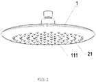
FIG. 2 illustrates a schematic view of the shower head in a water flowing state in the preferred embodiment of the present disclosure; -
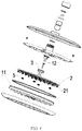
FIG. 3 illustrates an exploded perspective view of the shower head in the preferred embodiment of the present disclosure; -
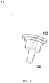
FIG. 4 illustrates a schematic view of an oblique water body in the preferred embodiment of the present disclosure; -
FIG. 5 illustrates a schematic view of an impeller in the preferred embodiment of the present disclosure; -
FIG. 6 illustrates a schematic view of a moving member in the preferred embodiment of the present disclosure; -
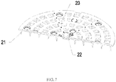
FIG. 7 illustrates a schematic view of a deposit removal needle plate in the preferred embodiment of the present disclosure; -
FIG. 8 illustrates a sectional view of the shower head in a no water flowing state in the preferred embodiment of the present disclosure; and -
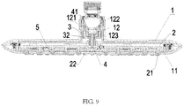
FIG. 9 illustrates a sectional view of the shower head in a water flowing state in the preferred embodiment of the present disclosure. - The present disclosure will be further described below with the combination of the accompanying drawings together with the embodiments.
- Referring to
FIGS. 1-9 , a self-cleaning water outlet device in this embodiment is preferably but not limited to a shower head. The shower head comprises abody 1, a depositremoval needle plate 2 disposed in thebody 1, and arotatable member 3 driven to rotate about an axial direction by flowing water. - An axial direction of the deposit
removal needle plate 2 and an axial direction of awater outlet cover 11 are coaxial. The depositremoval needle plate 2 comprises a plurality ofneedles 21, and the depositremoval needle plate 2 is swingably connected to therotatable member 3. - When water flows into the self-cleaning water outlet device, the water drives the
rotatable member 3 to rotate, and therotatable member 3 drives each of the plurality ofneedles 21 to swing about the axial direction in a corresponding one of a plurality of water outlet holes 111 of thewater outlet cover 11. Each of the plurality ofneedles 21 rubs against sediment deposited on an inner wall of a corresponding one of the plurality of water outlet holes 111 during a swinging process. Therefore, the sediment deposited on the inner wall of each of the plurality of water outlet holes 111 falls off when a corresponding one of the plurality of needles swing. Compared with the traditional needle moving in an axial direction thereof, when using the deposit removal method disclosed in this embodiment, the sediment deposited to the inner wall of each of the plurality of water outlet hole falls off more thoroughly, and the deposit removal effect is good. Therefore, the disadvantages in the conventional deposit removal method (i.e., that the sediment between the plurality of needles and the inner walls of the plurality of water outlet holes cannot be removed) are solved. - In this embodiment, the
body 1 is disposed with anoblique water body 12, and theoblique water body 12 comprises achamber 121. In an axial direction, a first end of thechamber 121 is disposed with awater inlet 122. A sidewall of thechamber 121 is disposed with a plurality ofoblique water outlets 123 arranged along a circumferential direction, so that the water flowing along the axial direction is converted into the oblique water flowing along an inclined direction by theoblique water body 12. - The
rotatable member 3 is an impeller disposed outside of the sidewall of thechamber 121 of theoblique water body 12. The water flows into the impeller from the plurality ofoblique water outlets 123, and blades of the impeller are impacted to drive the impeller to rotate by the water. - In order to cause the impeller driving the deposit
removal needle plate 2 to swing, a first side of the impeller facing the depositremoval needle plate 2 extends downward in the axial direction to form acam 31. A first side of the depositremoval needle plate 2 facing theoblique water body 12 extends upward in an axial direction to form a connectingmember 22. Thecam 31 is inserted into the connectingmember 22, and a sidewall of thecam 31 abuts a side of a sidewall of the connectingmember 22, so that when the impeller rotates, thecam 31 rotates in the connectingmember 22 and an abutting force between the sidewall of thecam 31 and the connectingmember 22 drives the depositremoval needle plate 2 to swing. - At the same time, in order to obtain a normal water outflow of the shower head, the water flowing into the impeller also needs to flow out from the plurality of water outlet holes 111 of the
water outlet cover 11. Therefore, in the axial direction, the impeller comprises with at least onewater outlet 32 at a lower end. The water flows out from theoblique water outlet 123 to enter into the impeller, and then flows out from the at least onewater outlet 32 to the depositremoval needle plate 2. In the axial direction, the depositremoval needle plate 2 comprises a plurality ofoverflow holes 23, and the water flows from the plurality ofoverflow holes 23 into the plurality of water outlet holes 111 of thewater outlet cover 11, thus forming the normal shower water. - At this point, a first purpose of the normal water outflow of the shower head and a second purpose of removing deposits while the water is flowing have been achieved. However, the aforementioned technical solution requires that each of the plurality of
needles 21 be always located in a corresponding one of the plurality of water outlet holes 111. After the water is shut off, there is residual water in a gap between each of the plurality ofneedles 21 and the corresponding one of the plurality of water outlet holes 111. It is easy to generate bacteria between each of the plurality ofneedles 21 and the corresponding one of the plurality of water outlet holes 111 if the residual water is not drained out. Therefore, if the plurality ofneedles 21 can be moved into the plurality of water outlet holes 111 to remove deposits during water flows, and the plurality ofneedles 21 can be removed from the plurality of water outlet holes 111 after the water is shut off, so that the residual water in the plurality of water outlet holes 111 can be completely drained out, the technical solution is more reasonable. - In order to achieve the aforementioned effects, in this embodiment, the
body 1 further comprises amovable member 4. Themovable member 4 is driven by the flowing water and moves in an axial direction. The depositremoval needle plate 2 and themovable member 4 are connected in the axial direction. When water flows into the shower head, the water flows to drive themovable member 4 to drive the depositremoval needle plate 2 to move downward in the axial direction, so that each of the plurality ofneedles 21 moves into a corresponding one of the plurality of water outlet holes 111 of thewater outlet cover 11. This causes each of the plurality ofneedles 21 to enter the corresponding one of the plurality of water outlet holes 111, enabling the removal of the deposits when the water flows. - Further, in order to cause each of the plurality of
needles 21 to be removed from the corresponding one of the plurality of water outlet holes 111 when the water is shut off, areset member 5 is disposed between the depositremoval needle plate 2 and thewater outlet cover 11. When the depositremoval needle plate 2 moves downward in the axial direction, thereset member 5 accumulates an elastic reset force. Therefore, when the water is shut off, the elastic reset force drives the depositremoval needle plate 2 to move upward and reset in the axial direction. - In order to install the moving
member 4, in the axial direction, a second end of thechamber 121 away from thewater inlet 122 is disposed with a throughhole 124. A first end of themovable member 4 passes through the throughhole 124, abuts the depositremoval needle plate 2 is linked to the depositremoval needle plate 2. A second end of themovable member 4 is located in thechamber 121. When water flows from thewater inlet 122 into thechamber 121, the water collides against themovable member 4 to drive themovable member 4 to move downward in the axial direction. - In an axial direction, the
cam 31 comprises a locatinghole 33. Themovable member 4 is inserted into the connectingmember 22 through the locatinghole 33 and, in the axial direction, abuts a bottom end surface of the connectingmember 22. - In this embodiment, in order to further optimize an efficiency of deposit removing, the second end of the
movable member 4 disposed in thechamber 121 is awater storage end 41. When no water flows into thechamber 121 from thewater inlet 122, thereset member 5 drives the depositremoval needle plate 2 to move upward in the axial direction, so that thewater storage end 41 moves upward to thewater inlet 122 in the axial direction. - The purpose of the aforementioned assembly is that the
water storage end 41 has a certain water storage function when the water flows. Only when the water pressure reaches a certain value does the movingmember 4 move downward in the axial direction to completely open thewater inlet 122. This allows the water flow rate entering into thechamber 121 to be relatively fast, and an initial rotation speed of the impeller to be relatively fast. Therefore, a swinging speed of the plurality ofneedles 21 is also increased, and a friction between the plurality ofneedles 21 and the inner walls of the plurality of water outlet holes 111 is increased, so that a strength of deposit removing is increased. - A self-cleaning water outlet device of
Embodiment 2 differs fromEmbodiment 1 in that the depositremoval needle plate 2 is a flowing water switchable member, and the flowing water switchable member comprises a plurality of switchable units. A direction of the flowing water in the plurality of water outlet holes 111 is changed in accordance with a swing movement of the plurality of switchable units during a swinging process. The self-cleaning water outlet device can form a large particle water spray pattern in which the water droplets are cone-shaped, a distribution of the water spray pattern is more uniform, a coverage is large, a pulse effect is achieved, and a shower experience is excellent. - It will be apparent to those skilled in the art that various modifications and variation can be made in the present disclosure without departing from the spirit or scope of the invention. Thus, it is intended that the present disclosure cover the modifications and variations of this invention provided they come within the scope of the appended claims and their equivalents.
- The self-cleaning water outlet device provided by the present disclosure drives the deposit removal needle plate to swing by the rotation of the impeller, thereby causing the plurality of needles to swing about the axial direction in the water outlet hole of the water outlet cover. The plurality of needles abut the inner walls of the plurality of water outlet holes during the swinging process, so that the sediment attached to the inner walls of the plurality of water outlet holes falls off as the plurality of needles swing. During the water discharge process, the plurality of needles swing about an axial direction in the plurality of water outlet holes of a water outlet cover, so that the sediment attached to the inner walls of the water outlet holes is automatically removed. An application range of the present disclosure is broad, and the present disclosure has a good industrial applicability.
Claims (22)
- A self-cleaning water outlet device, comprising:a body (1),a deposit removal needle plate (2) disposed in the body (1), anda rotatable member (3) driven to rotate about an axial direction by flowing water, characterized in that:an axial direction of the deposit removal needle plate (2) and an axial direction of the water outlet cover (11) are coaxial,the deposit removal needle plate (2) comprises a plurality of needles (21),the deposit removal needle plate (2) is swingably connected to the rotatable member (3), andwhen water flows into the water outlet device:the water drives the rotatable member (3) to rotate,the rotatable member (3) drives each of the plurality of needles (21) to swing about the axial direction in a corresponding one of the plurality of water outlet holes (111) of the water outlet cover (11), andeach of the plurality of needles (21) rubs against sediment deposited on an inner wall of the corresponding one of the plurality of water outlet holes (111) while each of the plurality of needles (21) are swinging to dislodge the sediment of the inner wall of the corresponding one of the plurality of water outlet holes (111).
- The self-cleaning water outlet device according to claim 1, characterized in that:the body (1) comprises an oblique water body (12),the oblique water body (12) comprises a chamber (121),in an axial direction, a first end of the chamber (121) is disposed with a water inlet (122), anda sidewall of the chamber (121) is disposed with a plurality of oblique water outlets (123) arranged along a circumferential direction.
- The self-cleaning water outlet device according to claim 2, characterized in that:the rotatable member (3) is an impeller disposed outside of the sidewall of the chamber (121) of the oblique water body (12),the water flows into the impeller from the plurality of oblique water outlets (123), andblades of the impeller are impacted to drive the impeller to rotate by the water.
- The self-cleaning water outlet device according to claim 3, characterized in that:a first side of the impeller facing the deposit removal needle plate (2) extends downward in the axial direction to form a cam (31),a first side of the deposit removal needle plate (2) facing the oblique water body (12) extends upward in the axial direction to form a connecting member (22),the cam (31) is disposed in the connecting member (22), anda sidewall of the cam (31) abuts a sidewall of the connecting member (22) to define a swing connection.
- The self-cleaning water outlet device according to claim 4, characterized in that:the impeller is disposed with at least one water outlet (32) at, in the axial direction, a lower end of the impeller,the water flows out from the plurality of oblique water outlets (123), enters into the impeller, flows out from the at least one water outlet (32), and then flows to the deposit removal needle plate (2),the deposit removal needle plate (2) is disposed with at least one overflow hole (23) disposed in the axial direction, andthe water flows from the at least one overflow hole (23) into the plurality of water outlet holes (111) of the water outlet cover (11).
- The self-cleaning water outlet device according to claim 5, further comprising:
a movable member (4), characterized in that:the movable member (4) is driven by the water and moves in an axial direction,the deposit removal needle plate (2) and the moving member (4) are connected in the axial direction, andwhen the water flows into the water outlet device:the water flows to drive the movable member (4) to drive the deposit removal needle plate (2) to move downward in the axial direction, andeach of the plurality of needles (21) move into the corresponding one of the plurality of water outlet holes (111) of the water outlet cover (11). - The self-cleaning water outlet device according to claim 6, characterized in that:in the axial direction, a second end of the chamber (121) away from the water inlet (122) is disposed with a through hole (124),a first end of the movable member (4) passes through the through hole (124) and abuts the deposit removal needle plate (2) and is linked to the deposit removal needle plate (2),a second end of the movable member (4) is disposed in the chamber (121), andwhen the water flows from the water inlet (122) into the chamber (121):
an impact force generated by the water flowing on the movable member (4) drives the movable member (4) to move downward in the axial direction. - The self-cleaning water outlet device according to claim 7, characterized in that:in an axial direction, the cam (31) is disposed with a locating hole (33), andthe movable member (4) is inserted into the connecting member (22) through the locating hole (33) and abuts, in the axial direction, a bottom end surface of the connecting member (22).
- The self-cleaning water outlet device according to claim 8, characterized in that:a reset member (5) is disposed between the deposit removal needle plate (2) and the water outlet cover (11), andwhen the deposit removal needle plate (2) moves downward in the axial direction:
the reset member (5) accumulates an elastic reset force. - The self-cleaning water outlet device according to claim 9, characterized in that:the second end of the movable member (4) disposd in the chamber (121) is a water storage end (41), andwhen no water flows into the chamber (121) from the water inlet (122):the reset member (5) drives the deposit removal needle plate (2) to move upward in the axial direction, andthe water storage end (41) moves upward, in an axial direction, toward the water inlet (122).
- A swinging water outlet device, comprising:a body (1),a flowing water switchable member (2) disposed in the body (1), anda rotatable member (3) driven to rotate about an axial direction by flowing water, characterized in that:an axial direction of the flowing water switchable member (2) and an axial direction of the water outlet cover (11) are coaxial,the flowing water switchable member (2) comprises a plurality of switchable units (21),the flowing water switchable member (2) is swingably connected to the rotatable member (3), andwhen water flows into the water outlet device:the water drives the rotatable member (3) to rotate,the rotatable member (3) drives each of the plurality of switchable units (21) to swing about the axial direction in a corresponding one of the plurality of water outlet holes (111) of the water outlet cover (11), anda flow direction of the water in each of the plurality of water outlet holes (111) changes due to a swing movement of a corresponding one of the plurality of switchable units (21).
- The swinging water outlet device according to claim 11, characterized in that:the body (1) comprises an oblique water body (12),the oblique water body (12) comprises a chamber (121),in an axial direction, a first end of the chamber (121) is disposed with a water inlet (122), anda sidewall of the chamber (121) is disposed with a plurality of oblique water outlets (123) arranged along a circumferential direction.
- The swinging water outlet device according to claim 12, characterized in that:the rotatable member (3) is an impeller disposed outside of the sidewall of the chamber (121) of the oblique water body,the water flows into the impeller from the plurality of oblique water outlets (123), andblades of the impeller are impacted to drive the impeller to rotate by the water.
- The swinging water outlet device according to claim 13, characterized in that:a first side of the impeller facing the flowing water switchable member (2) extends downward in the axial direction to form a cam (31),a first side of the flowing water switchable member (2) facing the oblique water body (12) extends upward in the axial direction to form a connecting member (22),the cam (31) is disposed in the connecting member (22), anda sidewall of the cam (31) abuts a sidewall of the connecting member (22) to define a swing connection.
- The swinging water outlet device according to claim 14, characterized in that:the impeller is disposed with at least one water outlet (32) at, in the axial direction, a lower end of the impeller,the water flows out from the plurality of oblique water outlets (123), enters into the impeller, flows out from the at least one water outlet (32), and flows to the flowing water switchable member (2),the flowing water switchable member (2) is disposed with at least one overflow hole (23) disposed in the axial direction, andthe water flows from the at least one overflow hole (23) into the plurality of water outlet holes (111) of the water outlet cover (11).
- The swinging water outlet device according to claim 15, further comprising:
a movable member, characterized in that:the movable member (4) is driven by the water and moves in an axial direction,the flowing water switchable member (2) and the moving member (4) are connected in the axial direction, andwhen the water flows into the water outlet device:the water flows to drive the movable member (4) to drive the flowing water switchable member (2) to move downward in the axial direction, andeach of the plurality of switchable units (21) move into the corresponding one of the plurality of water outlet holes (111) of the water outlet cover (11). - The swinging water outlet device according to claim 16, characterized in that:in the axial direction, a second end of the chamber (121) away from the water inlet (122) is disposed with a through hole (124),a first end of the movable member (4) passes through the through hole (124) and abuts the flowing water switchable member (2) and is linked to the flowing water switchable member (2),a second end of the movable member (4) is disposed in the chamber (121), andwhen the water flows from the water inlet (122) into the chamber (121):
an impact force generated by the water flowing on the movable member (4) drives the movable member (4) to move downward in the axial direction. - The swinging water outlet device according to claim 17, characterized in that:in an axial direction, the cam (31) is disposed with a locating hole (33), andthe movable member (4) is inserted into the connecting member (22) through the locating hole (33) and abuts, in the axial direction, a bottom end surface of the connecting member (22).
- The swinging water outlet device according to claim 18, characterized in that:a reset member (5) is disposed between the flowing water switchable member (2) and the water outlet cover (11), andwhen the flowing water switchable member (2) moves downward in the axial direction,
the reset member (5) accumulates an elastic reset force. - The swinging water outlet device according to claim 19, characterized in that:the second end of the movable member (4) disposd in the chamber (121) is a water storage end (41), andwhen no water flows into the chamber (121) from the water inlet (122):the reset member (5) drives the flowing water switchable member (2) to move upward in the axial direction, andthe water storage end (41) moves upward, in an axial direction, toward the water inlet (122).
- A shower head with a swinging water outlet device, comprising:a shower body (1),a deposit removal needle plate (2) disposed in the shower body (1), anda rotatable member (3) driven to rotate about an axial direction by flowing water, characterized in that:an axial direction of the deposit removal needle plate (2) and an axial direction of the water outlet cover (11) are coaxially,the deposit removal needle plate (2) comprises a plurality of needles (21),the deposit removal needle plate (2) is swingably connected to the rotatable member (3), andwhen water flows into the water outlet device:the water flow drives the rotatable member (3) to rotate,the rotatable member (3) drives each of the plurality of needles (21) to swing about the axial direction in a corresponding one of the plurality of the water outlet holes (111) of the water outlet cover (11), andeach of the plurality of needles (21) rub against sediment deposited on an inner wall of the corresponding one of the plurality of water outlet holes (111) while each of the plurality of needles (21) are swinging to dislodge the sediment of the inner wall of the corresponding one of the plurality of water outlet holes (111).
- The shower head with a swinging water outlet device according to claim 21, characterized in that:the deposit removal needle plate (2) is a flowing water switchable member (2),the flowing water switchable member (2) comprises a plurality of switchable units (21), andwhen water flows into the water outlet device,the water drives the rotatable member (3) to rotate,the rotatable member (3) drives each of the plurality of switchable units (21) to swing about the axial direction in the corresponding one of the plurality of water outlet holes (111) of the water outlet cover (11), anda flow direction of the water in each of the plurality of water outlet holes (111) changes due to a swing movement of a corresponding one of the plurality of switchable units (21).
Applications Claiming Priority (3)
| Application Number | Priority Date | Filing Date | Title |
|---|---|---|---|
| CN201720480295.6U CN207119498U (en) | 2017-05-03 | 2017-05-03 | Automatically cleaning discharging device and swing water discharging device |
| CN201710303792.3A CN109225734B (en) | 2017-05-03 | 2017-05-03 | A self-cleaning water outlet device and an oscillating water outlet device |
| PCT/CN2018/085302 WO2018202030A1 (en) | 2017-05-03 | 2018-05-02 | Water outflow device capable of self-cleaning and water outflow device capable of varying water flow |
Publications (3)
| Publication Number | Publication Date |
|---|---|
| EP3628409A1 true EP3628409A1 (en) | 2020-04-01 |
| EP3628409A4 EP3628409A4 (en) | 2021-01-06 |
| EP3628409B1 EP3628409B1 (en) | 2025-01-29 |
Family
ID=64016795
Family Applications (1)
| Application Number | Title | Priority Date | Filing Date |
|---|---|---|---|
| EP18795145.4A Active EP3628409B1 (en) | 2017-05-03 | 2018-05-02 | Water outflow device capable of self-cleaning and water outflow device capable of varying water flow |
Country Status (3)
| Country | Link |
|---|---|
| US (1) | US11433414B2 (en) |
| EP (1) | EP3628409B1 (en) |
| WO (1) | WO2018202030A1 (en) |
Families Citing this family (5)
| Publication number | Priority date | Publication date | Assignee | Title |
|---|---|---|---|---|
| CN114368846B (en) * | 2022-01-11 | 2022-10-21 | 北京四良科技有限公司 | Anti-blocking aeration head capable of filtering residues in biogas slurry |
| CN115400890B (en) * | 2022-01-25 | 2024-06-25 | 福建西河卫浴科技有限公司 | A water outlet device for rotating automatic descaling |
| CN114589017B (en) * | 2022-03-31 | 2023-10-13 | 厦门欧圣斯卫浴有限公司 | Swing water outlet mechanism |
| CN119345837B (en) * | 2024-12-24 | 2025-04-01 | 福建玮士迈科技有限公司 | Liquid distributor of chemical filler tower |
| CN121408006B (en) * | 2025-11-24 | 2026-04-03 | 北方国际合作股份有限公司 | A dust suppression device for open-pit coal mining |
Family Cites Families (16)
| Publication number | Priority date | Publication date | Assignee | Title |
|---|---|---|---|---|
| US2251192A (en) * | 1938-09-08 | 1941-07-29 | Mueller Co | Shower head |
| WO2000010720A1 (en) * | 1998-08-20 | 2000-03-02 | Ideal-Standard Gmbh | Shower head comprising nozzles moved on a displacement path |
| US6739527B1 (en) * | 2003-02-24 | 2004-05-25 | Shong I Copper Co., Ltd. | Shower head assembly |
| CA2618948C (en) * | 2004-08-13 | 2013-11-19 | Joseph H. Clearman | Spray apparatus and dispensing tubes therefor |
| US8794543B2 (en) * | 2006-12-28 | 2014-08-05 | Water Pik, Inc. | Low-speed pulsating showerhead |
| FR2934508A3 (en) * | 2008-07-29 | 2010-02-05 | Kaddour Raissi | PROJECTION DEVICE DELIVERING ONE OR MORE PURE ORBITAL FLUID JETS OR PARTICLE CHARGERS |
| WO2014019046A1 (en) * | 2012-08-02 | 2014-02-06 | Fabrimar S/A Indústria E Comércio | Showerhead |
| EP2767347A1 (en) * | 2013-02-13 | 2014-08-20 | Jiangmen Fenix Shower Products Technology Co., Ltd. | A self-cleaning shower |
| CN203935930U (en) * | 2014-04-22 | 2014-11-12 | 厦门明合卫浴设备有限公司 | The gondola water faucet with self-cleaning function |
| CN104307673A (en) * | 2014-09-30 | 2015-01-28 | 厦门吉科卫浴有限公司 | Top-jetting cleaning device |
| CN204276183U (en) * | 2014-11-04 | 2015-04-22 | 东莞市适意洁具有限公司 | A top spray that automatically cleans the water outlet |
| CN105498994B (en) * | 2016-01-15 | 2018-04-17 | 厦门水大卫浴洁具有限公司 | A kind of kinetic cleaning discharging device |
| CN205701133U (en) * | 2016-03-25 | 2016-11-23 | 福建西河卫浴科技有限公司 | A kind of sealing scale removal mechanism and be equiped with the gondola water faucet of sealing scale removal mechanism |
| CN205833405U (en) * | 2016-07-22 | 2016-12-28 | 九牧厨卫股份有限公司 | A kind of automatic descaling shower head |
| CN106076678B (en) * | 2016-07-22 | 2018-06-12 | 九牧厨卫股份有限公司 | A kind of automatic descaling shower head and shower are from descaling method |
| CN207119498U (en) * | 2017-05-03 | 2018-03-20 | 厦门松霖科技股份有限公司 | Automatically cleaning discharging device and swing water discharging device |
-
2018
- 2018-05-02 EP EP18795145.4A patent/EP3628409B1/en active Active
- 2018-05-02 WO PCT/CN2018/085302 patent/WO2018202030A1/en not_active Ceased
-
2019
- 2019-11-04 US US16/673,918 patent/US11433414B2/en active Active
Also Published As
| Publication number | Publication date |
|---|---|
| EP3628409A4 (en) | 2021-01-06 |
| US11433414B2 (en) | 2022-09-06 |
| EP3628409B1 (en) | 2025-01-29 |
| WO2018202030A1 (en) | 2018-11-08 |
| US20200061658A1 (en) | 2020-02-27 |
Similar Documents
| Publication | Publication Date | Title |
|---|---|---|
| US11433414B2 (en) | Self-cleaning water outlet device and a swinging water outlet device | |
| CN207119498U (en) | Automatically cleaning discharging device and swing water discharging device | |
| CN105435979B (en) | A kind of shower with automatically descaling function | |
| AU2014388132B2 (en) | Dishwasher comprising at least one dishwasher spray arm | |
| CN105944852B (en) | A shower with an anti-dirt ball | |
| CN104840115A (en) | Vegetable washing basin, vegetable washing method and vegetable washing machine | |
| CN208815145U (en) | A kind of spray equipment in electrophoresis coating technique | |
| CN106000684A (en) | An anti-clogging shower | |
| CN206801947U (en) | A kind of open water pump and water tank cleaner | |
| CN109225734B (en) | A self-cleaning water outlet device and an oscillating water outlet device | |
| CN110811340A (en) | Steam ager that possesses self-cleaning function | |
| CN107854091A (en) | Water basin dish-washing machine | |
| CN108457354A (en) | Pre-wetting nozzle and pre-wetting method for intelligent closestool | |
| CN110680198A (en) | Spray head device and steam box using same | |
| WO2020036558A2 (en) | A dishwasher with improved washing performance | |
| CN216495189U (en) | Spraying device and dish-washing machine | |
| CN114472412B (en) | Environment-friendly tissue culture bottle automatic cleaning machine | |
| CN105383449A (en) | Wheel washing device | |
| JP4726533B2 (en) | Spray nozzle for dishwasher | |
| JP5848004B2 (en) | Cooking pot cleaning equipment | |
| CN208435520U (en) | sink dishwasher | |
| CN106000683B (en) | An anti-clogging shower with a cleaner | |
| CN105105662A (en) | Fruit and vegetable cleaning machine | |
| CN205761879U (en) | A kind of anti-block shower | |
| CN114472413B (en) | A compact tissue culture bottle automatic cleaning machine |
Legal Events
| Date | Code | Title | Description |
|---|---|---|---|
| STAA | Information on the status of an ep patent application or granted ep patent |
Free format text: STATUS: THE INTERNATIONAL PUBLICATION HAS BEEN MADE |
|
| PUAI | Public reference made under article 153(3) epc to a published international application that has entered the european phase |
Free format text: ORIGINAL CODE: 0009012 |
|
| STAA | Information on the status of an ep patent application or granted ep patent |
Free format text: STATUS: REQUEST FOR EXAMINATION WAS MADE |
|
| 17P | Request for examination filed |
Effective date: 20191202 |
|
| AK | Designated contracting states |
Kind code of ref document: A1 Designated state(s): AL AT BE BG CH CY CZ DE DK EE ES FI FR GB GR HR HU IE IS IT LI LT LU LV MC MK MT NL NO PL PT RO RS SE SI SK SM TR |
|
| AX | Request for extension of the european patent |
Extension state: BA ME |
|
| DAV | Request for validation of the european patent (deleted) | ||
| DAX | Request for extension of the european patent (deleted) | ||
| A4 | Supplementary search report drawn up and despatched |
Effective date: 20201207 |
|
| RIC1 | Information provided on ipc code assigned before grant |
Ipc: B05B 15/522 20180101ALI20201201BHEP Ipc: B05B 1/08 20060101ALI20201201BHEP Ipc: B05B 3/04 20060101ALI20201201BHEP Ipc: B05B 15/00 20180101AFI20201201BHEP Ipc: B05B 1/18 20060101ALI20201201BHEP |
|
| STAA | Information on the status of an ep patent application or granted ep patent |
Free format text: STATUS: EXAMINATION IS IN PROGRESS |
|
| 17Q | First examination report despatched |
Effective date: 20220822 |
|
| GRAP | Despatch of communication of intention to grant a patent |
Free format text: ORIGINAL CODE: EPIDOSNIGR1 |
|
| STAA | Information on the status of an ep patent application or granted ep patent |
Free format text: STATUS: GRANT OF PATENT IS INTENDED |
|
| INTG | Intention to grant announced |
Effective date: 20240902 |
|
| GRAS | Grant fee paid |
Free format text: ORIGINAL CODE: EPIDOSNIGR3 |
|
| GRAA | (expected) grant |
Free format text: ORIGINAL CODE: 0009210 |
|
| STAA | Information on the status of an ep patent application or granted ep patent |
Free format text: STATUS: THE PATENT HAS BEEN GRANTED |
|
| AK | Designated contracting states |
Kind code of ref document: B1 Designated state(s): AL AT BE BG CH CY CZ DE DK EE ES FI FR GB GR HR HU IE IS IT LI LT LU LV MC MK MT NL NO PL PT RO RS SE SI SK SM TR |
|
| REG | Reference to a national code |
Ref country code: GB Ref legal event code: FG4D |
|
| REG | Reference to a national code |
Ref country code: CH Ref legal event code: EP |
|
| REG | Reference to a national code |
Ref country code: DE Ref legal event code: R096 Ref document number: 602018078851 Country of ref document: DE |
|
| REG | Reference to a national code |
Ref country code: IE Ref legal event code: FG4D |
|
| REG | Reference to a national code |
Ref country code: NL Ref legal event code: MP Effective date: 20250129 |
|
| PG25 | Lapsed in a contracting state [announced via postgrant information from national office to epo] |
Ref country code: NL Free format text: LAPSE BECAUSE OF FAILURE TO SUBMIT A TRANSLATION OF THE DESCRIPTION OR TO PAY THE FEE WITHIN THE PRESCRIBED TIME-LIMIT Effective date: 20250129 |
|
| PG25 | Lapsed in a contracting state [announced via postgrant information from national office to epo] |
Ref country code: RS Free format text: LAPSE BECAUSE OF FAILURE TO SUBMIT A TRANSLATION OF THE DESCRIPTION OR TO PAY THE FEE WITHIN THE PRESCRIBED TIME-LIMIT Effective date: 20250429 |
|
| PG25 | Lapsed in a contracting state [announced via postgrant information from national office to epo] |
Ref country code: FI Free format text: LAPSE BECAUSE OF FAILURE TO SUBMIT A TRANSLATION OF THE DESCRIPTION OR TO PAY THE FEE WITHIN THE PRESCRIBED TIME-LIMIT Effective date: 20250129 |
|
| PG25 | Lapsed in a contracting state [announced via postgrant information from national office to epo] |
Ref country code: PL Free format text: LAPSE BECAUSE OF FAILURE TO SUBMIT A TRANSLATION OF THE DESCRIPTION OR TO PAY THE FEE WITHIN THE PRESCRIBED TIME-LIMIT Effective date: 20250129 |
|
| PGFP | Annual fee paid to national office [announced via postgrant information from national office to epo] |
Ref country code: DE Payment date: 20250531 Year of fee payment: 8 |
|
| PG25 | Lapsed in a contracting state [announced via postgrant information from national office to epo] |
Ref country code: ES Free format text: LAPSE BECAUSE OF FAILURE TO SUBMIT A TRANSLATION OF THE DESCRIPTION OR TO PAY THE FEE WITHIN THE PRESCRIBED TIME-LIMIT Effective date: 20250129 |
|
| REG | Reference to a national code |
Ref country code: LT Ref legal event code: MG9D |
|
| PG25 | Lapsed in a contracting state [announced via postgrant information from national office to epo] |
Ref country code: IS Free format text: LAPSE BECAUSE OF FAILURE TO SUBMIT A TRANSLATION OF THE DESCRIPTION OR TO PAY THE FEE WITHIN THE PRESCRIBED TIME-LIMIT Effective date: 20250529 Ref country code: NO Free format text: LAPSE BECAUSE OF FAILURE TO SUBMIT A TRANSLATION OF THE DESCRIPTION OR TO PAY THE FEE WITHIN THE PRESCRIBED TIME-LIMIT Effective date: 20250429 |
|
| REG | Reference to a national code |
Ref country code: AT Ref legal event code: MK05 Ref document number: 1762928 Country of ref document: AT Kind code of ref document: T Effective date: 20250129 |
|
| PG25 | Lapsed in a contracting state [announced via postgrant information from national office to epo] |
Ref country code: HR Free format text: LAPSE BECAUSE OF FAILURE TO SUBMIT A TRANSLATION OF THE DESCRIPTION OR TO PAY THE FEE WITHIN THE PRESCRIBED TIME-LIMIT Effective date: 20250129 |
|
| PG25 | Lapsed in a contracting state [announced via postgrant information from national office to epo] |
Ref country code: LV Free format text: LAPSE BECAUSE OF FAILURE TO SUBMIT A TRANSLATION OF THE DESCRIPTION OR TO PAY THE FEE WITHIN THE PRESCRIBED TIME-LIMIT Effective date: 20250129 Ref country code: PT Free format text: LAPSE BECAUSE OF FAILURE TO SUBMIT A TRANSLATION OF THE DESCRIPTION OR TO PAY THE FEE WITHIN THE PRESCRIBED TIME-LIMIT Effective date: 20250529 |
|
| PG25 | Lapsed in a contracting state [announced via postgrant information from national office to epo] |
Ref country code: GR Free format text: LAPSE BECAUSE OF FAILURE TO SUBMIT A TRANSLATION OF THE DESCRIPTION OR TO PAY THE FEE WITHIN THE PRESCRIBED TIME-LIMIT Effective date: 20250430 Ref country code: BG Free format text: LAPSE BECAUSE OF FAILURE TO SUBMIT A TRANSLATION OF THE DESCRIPTION OR TO PAY THE FEE WITHIN THE PRESCRIBED TIME-LIMIT Effective date: 20250129 |
|
| PG25 | Lapsed in a contracting state [announced via postgrant information from national office to epo] |
Ref country code: AT Free format text: LAPSE BECAUSE OF FAILURE TO SUBMIT A TRANSLATION OF THE DESCRIPTION OR TO PAY THE FEE WITHIN THE PRESCRIBED TIME-LIMIT Effective date: 20250129 |
|
| PG25 | Lapsed in a contracting state [announced via postgrant information from national office to epo] |
Ref country code: SE Free format text: LAPSE BECAUSE OF FAILURE TO SUBMIT A TRANSLATION OF THE DESCRIPTION OR TO PAY THE FEE WITHIN THE PRESCRIBED TIME-LIMIT Effective date: 20250129 |
|
| PG25 | Lapsed in a contracting state [announced via postgrant information from national office to epo] |
Ref country code: SM Free format text: LAPSE BECAUSE OF FAILURE TO SUBMIT A TRANSLATION OF THE DESCRIPTION OR TO PAY THE FEE WITHIN THE PRESCRIBED TIME-LIMIT Effective date: 20250129 |
|
| PG25 | Lapsed in a contracting state [announced via postgrant information from national office to epo] |
Ref country code: DK Free format text: LAPSE BECAUSE OF FAILURE TO SUBMIT A TRANSLATION OF THE DESCRIPTION OR TO PAY THE FEE WITHIN THE PRESCRIBED TIME-LIMIT Effective date: 20250129 |
|
| PG25 | Lapsed in a contracting state [announced via postgrant information from national office to epo] |
Ref country code: IT Free format text: LAPSE BECAUSE OF FAILURE TO SUBMIT A TRANSLATION OF THE DESCRIPTION OR TO PAY THE FEE WITHIN THE PRESCRIBED TIME-LIMIT Effective date: 20250129 |
|
| PG25 | Lapsed in a contracting state [announced via postgrant information from national office to epo] |
Ref country code: EE Free format text: LAPSE BECAUSE OF FAILURE TO SUBMIT A TRANSLATION OF THE DESCRIPTION OR TO PAY THE FEE WITHIN THE PRESCRIBED TIME-LIMIT Effective date: 20250129 Ref country code: CZ Free format text: LAPSE BECAUSE OF FAILURE TO SUBMIT A TRANSLATION OF THE DESCRIPTION OR TO PAY THE FEE WITHIN THE PRESCRIBED TIME-LIMIT Effective date: 20250129 |
|
| PG25 | Lapsed in a contracting state [announced via postgrant information from national office to epo] |
Ref country code: RO Free format text: LAPSE BECAUSE OF FAILURE TO SUBMIT A TRANSLATION OF THE DESCRIPTION OR TO PAY THE FEE WITHIN THE PRESCRIBED TIME-LIMIT Effective date: 20250129 |
|
| PG25 | Lapsed in a contracting state [announced via postgrant information from national office to epo] |
Ref country code: SK Free format text: LAPSE BECAUSE OF FAILURE TO SUBMIT A TRANSLATION OF THE DESCRIPTION OR TO PAY THE FEE WITHIN THE PRESCRIBED TIME-LIMIT Effective date: 20250129 |
|
| REG | Reference to a national code |
Ref country code: DE Ref legal event code: R097 Ref document number: 602018078851 Country of ref document: DE |
|
| PLBE | No opposition filed within time limit |
Free format text: ORIGINAL CODE: 0009261 |
|
| STAA | Information on the status of an ep patent application or granted ep patent |
Free format text: STATUS: NO OPPOSITION FILED WITHIN TIME LIMIT |
|
| REG | Reference to a national code |
Ref country code: CH Ref legal event code: L10 Free format text: ST27 STATUS EVENT CODE: U-0-0-L10-L00 (AS PROVIDED BY THE NATIONAL OFFICE) Effective date: 20251210 |
|
| REG | Reference to a national code |
Ref country code: CH Ref legal event code: H13 Free format text: ST27 STATUS EVENT CODE: U-0-0-H10-H13 (AS PROVIDED BY THE NATIONAL OFFICE) Effective date: 20251223 |
|
| 26N | No opposition filed |
Effective date: 20251030 |
|
| PG25 | Lapsed in a contracting state [announced via postgrant information from national office to epo] |
Ref country code: LU Free format text: LAPSE BECAUSE OF NON-PAYMENT OF DUE FEES Effective date: 20250502 |
|
| PG25 | Lapsed in a contracting state [announced via postgrant information from national office to epo] |
Ref country code: CH Free format text: LAPSE BECAUSE OF NON-PAYMENT OF DUE FEES Effective date: 20250531 |
|
| GBPC | Gb: european patent ceased through non-payment of renewal fee |
Effective date: 20250502 |
|
| REG | Reference to a national code |
Ref country code: BE Ref legal event code: MM Effective date: 20250531 |
|
| PG25 | Lapsed in a contracting state [announced via postgrant information from national office to epo] |
Ref country code: MC Free format text: LAPSE BECAUSE OF FAILURE TO SUBMIT A TRANSLATION OF THE DESCRIPTION OR TO PAY THE FEE WITHIN THE PRESCRIBED TIME-LIMIT Effective date: 20250129 |
|
| PG25 | Lapsed in a contracting state [announced via postgrant information from national office to epo] |
Ref country code: GB Free format text: LAPSE BECAUSE OF NON-PAYMENT OF DUE FEES Effective date: 20250502 |
|
| PG25 | Lapsed in a contracting state [announced via postgrant information from national office to epo] |
Ref country code: IE Free format text: LAPSE BECAUSE OF NON-PAYMENT OF DUE FEES Effective date: 20250502 |
|
| PG25 | Lapsed in a contracting state [announced via postgrant information from national office to epo] |
Ref country code: BE Free format text: LAPSE BECAUSE OF NON-PAYMENT OF DUE FEES Effective date: 20250531 |
|
| PG25 | Lapsed in a contracting state [announced via postgrant information from national office to epo] |
Ref country code: FR Free format text: LAPSE BECAUSE OF NON-PAYMENT OF DUE FEES Effective date: 20250531 |