EP3628396A2 - Fluid mixing system with flexible drive line and foldable impeller - Google Patents
Fluid mixing system with flexible drive line and foldable impeller Download PDFInfo
- Publication number
- EP3628396A2 EP3628396A2 EP19193563.4A EP19193563A EP3628396A2 EP 3628396 A2 EP3628396 A2 EP 3628396A2 EP 19193563 A EP19193563 A EP 19193563A EP 3628396 A2 EP3628396 A2 EP 3628396A2
- Authority
- EP
- European Patent Office
- Prior art keywords
- drive line
- container
- impeller
- drive shaft
- hub
- Prior art date
- Legal status (The legal status is an assumption and is not a legal conclusion. Google has not performed a legal analysis and makes no representation as to the accuracy of the status listed.)
- Granted
Links
Images













Classifications
-
- B—PERFORMING OPERATIONS; TRANSPORTING
- B01—PHYSICAL OR CHEMICAL PROCESSES OR APPARATUS IN GENERAL
- B01F—MIXING, e.g. DISSOLVING, EMULSIFYING OR DISPERSING
- B01F27/00—Mixers with rotary stirring devices in fixed receptacles; Kneaders
- B01F27/21—Mixers with rotary stirring devices in fixed receptacles; Kneaders characterised by their rotating shafts
- B01F27/212—Construction of the shaft
-
- B—PERFORMING OPERATIONS; TRANSPORTING
- B01—PHYSICAL OR CHEMICAL PROCESSES OR APPARATUS IN GENERAL
- B01F—MIXING, e.g. DISSOLVING, EMULSIFYING OR DISPERSING
- B01F27/00—Mixers with rotary stirring devices in fixed receptacles; Kneaders
- B01F27/80—Mixers with rotary stirring devices in fixed receptacles; Kneaders with stirrers rotating about a substantially vertical axis
- B01F27/90—Mixers with rotary stirring devices in fixed receptacles; Kneaders with stirrers rotating about a substantially vertical axis with paddles or arms
- B01F27/906—Mixers with rotary stirring devices in fixed receptacles; Kneaders with stirrers rotating about a substantially vertical axis with paddles or arms with fixed axis
-
- B—PERFORMING OPERATIONS; TRANSPORTING
- B01—PHYSICAL OR CHEMICAL PROCESSES OR APPARATUS IN GENERAL
- B01F—MIXING, e.g. DISSOLVING, EMULSIFYING OR DISPERSING
- B01F27/00—Mixers with rotary stirring devices in fixed receptacles; Kneaders
- B01F27/05—Stirrers
- B01F27/051—Stirrers characterised by their elements, materials or mechanical properties
- B01F27/054—Deformable stirrers, e.g. deformed by a centrifugal force applied during operation
- B01F27/0541—Deformable stirrers, e.g. deformed by a centrifugal force applied during operation with mechanical means to alter the position of the stirring elements
-
- B—PERFORMING OPERATIONS; TRANSPORTING
- B01—PHYSICAL OR CHEMICAL PROCESSES OR APPARATUS IN GENERAL
- B01F—MIXING, e.g. DISSOLVING, EMULSIFYING OR DISPERSING
- B01F27/00—Mixers with rotary stirring devices in fixed receptacles; Kneaders
- B01F27/05—Stirrers
- B01F27/07—Stirrers characterised by their mounting on the shaft
- B01F27/071—Fixing of the stirrer to the shaft
-
- B—PERFORMING OPERATIONS; TRANSPORTING
- B01—PHYSICAL OR CHEMICAL PROCESSES OR APPARATUS IN GENERAL
- B01F—MIXING, e.g. DISSOLVING, EMULSIFYING OR DISPERSING
- B01F27/00—Mixers with rotary stirring devices in fixed receptacles; Kneaders
- B01F27/05—Stirrers
- B01F27/07—Stirrers characterised by their mounting on the shaft
- B01F27/072—Stirrers characterised by their mounting on the shaft characterised by the disposition of the stirrers with respect to the rotating axis
- B01F27/0726—Stirrers characterised by their mounting on the shaft characterised by the disposition of the stirrers with respect to the rotating axis having stirring elements connected to the stirrer shaft each by a single radial rod, other than open frameworks
-
- B—PERFORMING OPERATIONS; TRANSPORTING
- B01—PHYSICAL OR CHEMICAL PROCESSES OR APPARATUS IN GENERAL
- B01F—MIXING, e.g. DISSOLVING, EMULSIFYING OR DISPERSING
- B01F27/00—Mixers with rotary stirring devices in fixed receptacles; Kneaders
- B01F27/05—Stirrers
- B01F27/11—Stirrers characterised by the configuration of the stirrers
- B01F27/112—Stirrers characterised by the configuration of the stirrers with arms, paddles, vanes or blades
- B01F27/1125—Stirrers characterised by the configuration of the stirrers with arms, paddles, vanes or blades with vanes or blades extending parallel or oblique to the stirrer axis
-
- B—PERFORMING OPERATIONS; TRANSPORTING
- B01—PHYSICAL OR CHEMICAL PROCESSES OR APPARATUS IN GENERAL
- B01F—MIXING, e.g. DISSOLVING, EMULSIFYING OR DISPERSING
- B01F27/00—Mixers with rotary stirring devices in fixed receptacles; Kneaders
- B01F27/05—Stirrers
- B01F27/11—Stirrers characterised by the configuration of the stirrers
- B01F27/112—Stirrers characterised by the configuration of the stirrers with arms, paddles, vanes or blades
- B01F27/1125—Stirrers characterised by the configuration of the stirrers with arms, paddles, vanes or blades with vanes or blades extending parallel or oblique to the stirrer axis
- B01F27/11253—Stirrers characterised by the configuration of the stirrers with arms, paddles, vanes or blades with vanes or blades extending parallel or oblique to the stirrer axis the blades extending oblique to the stirrer axis
-
- B—PERFORMING OPERATIONS; TRANSPORTING
- B01—PHYSICAL OR CHEMICAL PROCESSES OR APPARATUS IN GENERAL
- B01F—MIXING, e.g. DISSOLVING, EMULSIFYING OR DISPERSING
- B01F27/00—Mixers with rotary stirring devices in fixed receptacles; Kneaders
- B01F27/05—Stirrers
- B01F27/11—Stirrers characterised by the configuration of the stirrers
- B01F27/19—Stirrers with two or more mixing elements mounted in sequence on the same axis
- B01F27/191—Stirrers with two or more mixing elements mounted in sequence on the same axis with similar elements
-
- B—PERFORMING OPERATIONS; TRANSPORTING
- B01—PHYSICAL OR CHEMICAL PROCESSES OR APPARATUS IN GENERAL
- B01F—MIXING, e.g. DISSOLVING, EMULSIFYING OR DISPERSING
- B01F27/00—Mixers with rotary stirring devices in fixed receptacles; Kneaders
- B01F27/21—Mixers with rotary stirring devices in fixed receptacles; Kneaders characterised by their rotating shafts
- B01F27/211—Mixers with rotary stirring devices in fixed receptacles; Kneaders characterised by their rotating shafts characterised by the material of the shaft
- B01F27/2111—Flexible shafts
-
- B—PERFORMING OPERATIONS; TRANSPORTING
- B01—PHYSICAL OR CHEMICAL PROCESSES OR APPARATUS IN GENERAL
- B01F—MIXING, e.g. DISSOLVING, EMULSIFYING OR DISPERSING
- B01F27/00—Mixers with rotary stirring devices in fixed receptacles; Kneaders
- B01F27/80—Mixers with rotary stirring devices in fixed receptacles; Kneaders with stirrers rotating about a substantially vertical axis
- B01F27/88—Mixers with rotary stirring devices in fixed receptacles; Kneaders with stirrers rotating about a substantially vertical axis with a separate receptacle-stirrer unit that is adapted to be coupled to a drive mechanism
-
- B—PERFORMING OPERATIONS; TRANSPORTING
- B01—PHYSICAL OR CHEMICAL PROCESSES OR APPARATUS IN GENERAL
- B01F—MIXING, e.g. DISSOLVING, EMULSIFYING OR DISPERSING
- B01F35/00—Accessories for mixers; Auxiliary operations or auxiliary devices; Parts or details of general application
- B01F35/40—Mounting or supporting mixing devices or receptacles; Clamping or holding arrangements therefor
- B01F35/41—Mounting or supporting stirrer shafts or stirrer units on receptacles
-
- B—PERFORMING OPERATIONS; TRANSPORTING
- B01—PHYSICAL OR CHEMICAL PROCESSES OR APPARATUS IN GENERAL
- B01F—MIXING, e.g. DISSOLVING, EMULSIFYING OR DISPERSING
- B01F35/00—Accessories for mixers; Auxiliary operations or auxiliary devices; Parts or details of general application
- B01F35/40—Mounting or supporting mixing devices or receptacles; Clamping or holding arrangements therefor
- B01F35/41—Mounting or supporting stirrer shafts or stirrer units on receptacles
- B01F35/411—Mounting or supporting stirrer shafts or stirrer units on receptacles by supporting only one extremity of the shaft
- B01F35/4111—Mounting or supporting stirrer shafts or stirrer units on receptacles by supporting only one extremity of the shaft at the top of the receptacle
-
- B—PERFORMING OPERATIONS; TRANSPORTING
- B01—PHYSICAL OR CHEMICAL PROCESSES OR APPARATUS IN GENERAL
- B01F—MIXING, e.g. DISSOLVING, EMULSIFYING OR DISPERSING
- B01F35/00—Accessories for mixers; Auxiliary operations or auxiliary devices; Parts or details of general application
- B01F35/40—Mounting or supporting mixing devices or receptacles; Clamping or holding arrangements therefor
- B01F35/41—Mounting or supporting stirrer shafts or stirrer units on receptacles
- B01F35/412—Mounting or supporting stirrer shafts or stirrer units on receptacles by supporting both extremities of the shaft
- B01F35/4121—Mounting or supporting stirrer shafts or stirrer units on receptacles by supporting both extremities of the shaft at the top and at the bottom of the receptacle, e.g. for performing a conical orbital movement about a vertical axis
-
- B—PERFORMING OPERATIONS; TRANSPORTING
- B01—PHYSICAL OR CHEMICAL PROCESSES OR APPARATUS IN GENERAL
- B01F—MIXING, e.g. DISSOLVING, EMULSIFYING OR DISPERSING
- B01F35/00—Accessories for mixers; Auxiliary operations or auxiliary devices; Parts or details of general application
- B01F35/50—Mixing receptacles
- B01F35/513—Flexible receptacles, e.g. bags supported by rigid containers
-
- C—CHEMISTRY; METALLURGY
- C12—BIOCHEMISTRY; BEER; SPIRITS; WINE; VINEGAR; MICROBIOLOGY; ENZYMOLOGY; MUTATION OR GENETIC ENGINEERING
- C12M—APPARATUS FOR ENZYMOLOGY OR MICROBIOLOGY; APPARATUS FOR CULTURING MICROORGANISMS FOR PRODUCING BIOMASS, FOR GROWING CELLS OR FOR OBTAINING FERMENTATION OR METABOLIC PRODUCTS, i.e. BIOREACTORS OR FERMENTERS
- C12M23/00—Constructional details, e.g. recesses, hinges
- C12M23/02—Form or structure of the vessel
- C12M23/14—Bags
-
- C—CHEMISTRY; METALLURGY
- C12—BIOCHEMISTRY; BEER; SPIRITS; WINE; VINEGAR; MICROBIOLOGY; ENZYMOLOGY; MUTATION OR GENETIC ENGINEERING
- C12M—APPARATUS FOR ENZYMOLOGY OR MICROBIOLOGY; APPARATUS FOR CULTURING MICROORGANISMS FOR PRODUCING BIOMASS, FOR GROWING CELLS OR FOR OBTAINING FERMENTATION OR METABOLIC PRODUCTS, i.e. BIOREACTORS OR FERMENTERS
- C12M23/00—Constructional details, e.g. recesses, hinges
- C12M23/52—Mobile; Means for transporting the apparatus
-
- C—CHEMISTRY; METALLURGY
- C12—BIOCHEMISTRY; BEER; SPIRITS; WINE; VINEGAR; MICROBIOLOGY; ENZYMOLOGY; MUTATION OR GENETIC ENGINEERING
- C12M—APPARATUS FOR ENZYMOLOGY OR MICROBIOLOGY; APPARATUS FOR CULTURING MICROORGANISMS FOR PRODUCING BIOMASS, FOR GROWING CELLS OR FOR OBTAINING FERMENTATION OR METABOLIC PRODUCTS, i.e. BIOREACTORS OR FERMENTERS
- C12M27/00—Means for mixing, agitating or circulating fluids in the vessel
- C12M27/02—Stirrer or mobile mixing elements
Definitions
- the current mixing systems are useful, they have some limitations.
- the rigid drive shaft limits the ability to collapse or fold the flexible bag so as to reduce its size for transportation, storage and/or further processing.
- this system has the disadvantage of needing to clean and sterilize the drive shaft between different uses.
- the flexible bag is typically secured within the support housing prior to insertion of the drive shaft. It is thus necessary during use to vertically position the drive shaft over the top of the bag for insertion into the tube. For large bags or elongated bags that require a long drive shaft, this can be difficult to accomplish. Furthermore, in situations where the mixing system is located in a room with a relatively low ceiling, it may be impossible to vertically lift the drive shaft over the bag. This type of system also requires increased training in user operation to ensure that the drive shaft is properly received within the tube and properly engaged with the impeller so that the system operates as intended.
- rotational assembly 42A comprises an outer casing 50 having an outwardly projecting annular sealing flange 52 and an outwardly projecting annular mounting flange 53.
- a hub 54 is rotatably disposed within outer casing 50.
- One or more bearing assemblies 55 can be disposed between outer casing 50 and hub 54 to permit free and easy rotation of hub 54 relative to casing 50.
- one or more seals 56 can be formed between outer casing 50 and hub 54 so that during use an aseptic seal can be maintained between outer casing 50 and hub 54 as hub 54 rotates relative to outer casing 50.
- Second end 60 of hub 54 is coupled with a first end 70 of drive line 44. This coupling can be by overmolding, clamp, fastener, or other conventional techniques. Other configurations can also be used.
- container station 14 and docking station 12 are removably coupled together as shown in Figure 1 .
- One example of how docking station 12 and container assembly 16 can be coupled together is disclosed in US Patent Publication No. 2011/0310696 which was previously incorporated by reference. Other methods can also be used. Either before or after coupling together container station 14 and docking station 12, container assembly 16 is positioned within chamber 114 of support housing 100 and second rotational assembly 42B is secured to yoke 140 as discussed above.
- At least a portion of drive line 44 is sufficiently flexible so that the flexible portion of drive line 44 can be twisted under torsion about longitudinal axis 48 of drive line 44 over an angle of at least 15°, 25°, 45°, 90°, 180°, 360°, 720° or more without elastic deformation of drive line 44.
- at least a portion of drive line 44 is sufficiently flexible so that the flexible portion of drive line 44 can be bent or folded relative to a linear longitudinal axis 48 ( Figure 2 ) of drive line 44 over an angle ⁇ ( Figure 3 ) of at least 15°, 25°, 45°, 90°, 135°, 180° or more without elastic deformation of drive line 44.
- a second drive shaft could be coupled with hub 54 of second rotational assembly 42B though a hole formed in floor 110 of support housing 100.
- both ends 70 and 72 of drive line 44 could be concurrently rotated although there may still be some twisting of drive line 44 along a central length or adjacent to impeller 46.
- yoke 140 is mounted on the interior surface of floor 110 of support housing 100 for engaging with second rotational assembly 42B ( Figure 2 ).
- a yoke 140A can be mounted on the exterior surface of floor 110 of support housing 100.
- a hole 148 centrally extends through floor 100 so as to communicate with chamber 114.
- yoke 140A has an opening 149 that is bounded between a body 150 and a locking arm 152 hingedly mounted thereto. During use, with locking arm 152 in an open position, the free end of second rotational assembly 42B ( Figure 2 ) is passed down through hole 148 so as to be received within opening 149.
- means are provided for holding the lower end 24 of container 18 stationary while flexible drive line 44 is rotated within compartment 28 of container 18.
- this means includes yoke 140 mounted on the interior surface of floor 110, yoke 140A mounted on the exterior surface of floor 110 and yoke 140A mounted on a separate structure located below floor 110.
- Cover plate 186 is secured in place by engaging with locking fingers 188 that project from top surface 174 at spaced apart locations around pocket 176. In this configuration, cover plate 186 retains hub 178 within outer casing 168. It is appreciated that because pocket 176 is blind, it is not necessary to position a seal between hub 178 and outer casing 168, although a seal can be used if desired. It is also appreciated that the rotational assemblies can have a variety of other configurations.
- Foam breaker 156 disposed at an upper end of drive line 44 is a foam breaker 156.
- Foam breaker 156 includes a hub 157 secured to drive line 44 and a bar 158 that outwardly projects from opposing sides of hub 157.
- Foam breaker 156 rotates concurrently with drive line 44 to break up foam that is formed at the upper end of container 18. It is appreciated that foam breaker 156 can come in a variety of different configurations.
- each impeller 190 comprises a tubular hub 192 which can be advanced over drive line 44 and secured in place such as by crimping, clamp, fastener, welding, set screw or the like.
- a flange 194 encircles and radially outwardly projects from hub 192.
- Flange 194 has a first side face 196 and an opposing second side face 198 with a plurality of openings 200A extending therethrough adjacent to a perimeter edge of flange 194.
- Outwardly projecting from first side face 196 are a plurality of spaced apart stops 202 with each stop 202 being disposed adjacent to a corresponding opening 200A.
- Outwardly projecting from the end of each stop 202 is a key 204.
- Collapsing of the blades enables container 18 to be folded smaller, helps prevents blades 206 from puncturing container 18 and can result in less stress being placed on blade 206.
- each impeller 190 is rotated within the fluid contained within container 18, each of blades 206 catch the fluid and automatically move to the expanded position which is a more optimal position for mixing the fluid.
- impeller body In each of impellers 190, 225, and 230, the same impeller body can be used with blades of any desired configuration or size. Furthermore, the exchangeable blades need not be rotatable but can be designed to be fixed in the extended position. Such, modular impellers provide greater flexibility in being able to easily produce impellers having a desired configuration and mixing properties while maintaining a minimum number of stock parts.
- Impeller 238 is substantially identical to impeller 190 except that in contrast to hub 192 ( Figure 10 ) which is tubular and received over drive line 44, impeller 238 includes an elongated hub 240 having a first end 242 with a U-shaped connecter 244A formed thereat and an opposing second end 246 with a U-shape connector 244B formed thereat.
- Each of connectors 244A and B bound a slot 248 and have an opening 250 transversely extending therethrough.
- FIG 16 again depicts impeller 238.
- impeller 238 in Figure 16 is hingedly coupled to line portions 262A and B of a rigid drive line 264. That is, line portions 262A and B can have openings 256 extending therethrough and can be made of shafts, rods or tubes or the like that are comprised of or consist of metal, plastics, composites, or the like that are substantially rigid or have limited flexibility.
- line portions 262A and B can have a bend radius wrapped 90° that must be greater than 8 meters, 10 meters or 12 meters to prevent elastic deformation.
- One or more seals 276 can also be positioned between outer casing 50 and hub 162 to form a liquid-tight seal therebetween.
- An adapter 278 is coupled with hub 162 and has a stem 280 that projects away from hub 162.
- stem 280 can be integrally formed as a unitary structure with hub 162.
- impeller 190 Mounted on second end 356 of drive shaft 352 is impeller 190 as previously discussed herein. Rotation of drive shaft 356 causes blades 206 to move to the expanded position and mix the fluid within container 18. Impeller 190 can be replaced with the other impellers discussed herein having pivotable blades and can incorporate other alternative configurations as discussed herein. Again, as a result of pivotable blades 206, container 18 can be more fully collapsed around impeller 190 while minimizing risk of damage to container 18 and to blades 206.
- Rotational assembly 548 is mounted to first end 544 of tubular connector 542.
- Rotational assembly 548 comprises outer casing 50 having an outwardly projecting annular sealing flange 52 and an outwardly projecting mounting flange 53 as previously discussed.
- a tubular hub 454 is rotatably disposed within outer casing 50.
- One or more bearing assemblies as previously discussed, can be disposed between outer casing 50 and hub 554 to permit free and easy rotation of hub 554 relative to casing 50.
- one or more seals can be formed between outer casing 50 and hub 554 so that during use an aseptic seal can be maintained between outer casing 50 and hub 554.
- Hub 554 has an interior surface 556 that bounds an opening 558 extending therethrough. Interior surface 556 includes an engaging portion having a polygonal or other non-circular transverse cross section so that driver portion 68 of drive shaft 362, as also shown in Figure 21 , passing through opening 558 can engage the engaging portion and facilitate rotation of hub 554 by rotation of drive shaft 362.
- Hub 554 can also comprise a tubular stem 560 projecting away from outer casing 50. Hub 554 can couple with first end 544 of tubular connector 542 by stem 560 being received within first end 544. A pull tie, clamp, crimp or other fastener can then be used to further secure stem 560 to tubular connect 542 so that a liquid tight seal is formed therebetween. Other conventional connecting techniques can also be used.
- Impeller 564 comprises a central hub 566 having blades 206 pivotably coupled thereto through the use of flange 194 and retainer 220 as previously discussed with regard to Figure 11 .
- Hub 566 has a first end 570 with a blind socket 572 formed thereat.
- Socket 572 typically has a noncircular transverse cross section, such as polygonal, so that it can engage a driver portion 378 of drive shaft 362. Accordingly, when driver portion 378 is received within socket 572, driver portion 378 engages with impeller 564 such that rotation of drive shaft 362 facilities rotation of impeller 564.
- Impeller 564 can be attached to connector 542 by inserting first end 570 of hub 566 within connector 542 at second end 546. A pull tie, clamp, crimp, or other type of fastener can then be cinched around second end 546 of connector 542 so as to form a liquid tight sealed engagement between impeller 564 and connector 542.
- drive shaft 362 comprises a head section 364 and a shaft section 366 that can be coupled together by threaded connection or other techniques.
- Head section 364 has substantially the same configuration as drive shaft 17 discussed with regard to Figure 3 and thus like features head section 364 and drive shaft 17 will be identified by like reference characters.
- drive shaft 362 can be formed as a single piece member or from a plurality of attachable sections.
- Drive shaft 362 has a first end 368 and an opposing second end 370. Formed at first end 368 is a frustoconical engaging portion 88 as previously discussed with regard to Figure 3 . Formed at second end 370 of drive shaft 362 is driver portion 378.
- Driver portion 378 has a non-circular transverse cross section so that it can facilitate locking engagement within hub 466 of impeller 464.
- driver portion 378 has a polygonal transverse cross section.
- Driver portion 68 is also formed along drive shaft 362 toward first end 368.
- Driver portion 68 also has a non-circular transverse cross section and is positioned so that it can facilitate locking engagement within the engaging portion of rotational assembly 448.
- container 18 having impeller assembly 40C coupled thereto is received within support housing 100 ( Figure 1 ) and rotational assembly is secured to drive motor assembly 300 as previously discussed with regard to Figure 3 .
- Drive shaft 362 is advanced down through motor mount 312, hub 454 of rotational assembly 548, tubular connecter 542 and into hub 566 of impeller 564.
- rotation of drive shaft 362 by drive motor assembly 300 facilitates rotation of hub 554, tubular connecter 542 and impeller 564 relative to outer casing 50 of rotational assembly 548 and container 18.
- the rotation of impeller 564 causes blades 206 to move to the expanded position and mix the fluid within container 18.
- impeller assembly 40C, drive shaft 362 and the discrete components thereof can have a variety of different configuration and can be made of a variety of different materials.
- Alternative embodiments of and further disclosure with respect to impeller assembly 40C, drive shaft 362, and the components thereof are disclosed in US Patent No. 7,384,783, issued June 10, 2008 and US Patent Publication No. 2011/0188928, published August 4, 2011 which are incorporated herein in their entirety by specific reference.
- Fluid mixing system 10A comprises a container assembly 16D at least partially disposed within the compartment of a support housing 100A.
- Like elements between container assembly 16 and 16A and between support housing 100 and 100A are identified by like reference characters.
- disclosure and alternative embodiments as previously discussed with regard to container 16 and support housing 100 are also applicable to corresponding elements of container assembly 16A and support housing 100A.
- container assembly 16A comprises container 18 having flexible drive line 44 disposed therein.
- First end 70 of flexible drive line 44 is secured to upper end wall 33 of container 18 by rotational assembly 42A.
- mixing elements 400A-C Mounted on flexible drive line 44 as spaced apart locations are mixing elements 400A-C.
- Each of mixing element 400A-C can comprise a fixed blade impeller, such as previously discussed impeller 46, a foldable impeller, such as previously discussed impellers 190, 225, 230, 238, or other types of mixing elements.
- container assembly 16A can comprise one one, two, or four or more mixing elements 400.
- container assembly 16A has second end 72 of drive line 44 suspended above lower end wall 34.
- receiver 408 comprises an inner housing 414 that is securely fixed to flexible drive line 44 such as by crimping, adhesive, clamps, fasteners, or the like.
- Receiver 408 also includes an outer housing 416 that encircles inner housing 414.
- a bearing 418 such as a ball thrust bearing, roller thrust bearing, or other type of bearing, is disposed between inner housing 414 and outer housing 416. Bearing 418 enables inner housing 414 and drive line 44 to rotate concurrently relative to outer housing 416.
- Outer housing 416 includes a body 420 having a tubular stem 422 outwardly projecting therefrom. Stem 422 can be integrally formed with or secured to body 420.
- An annular barb 423 can encircle and outwardly project on the end of stem 422 for engaging with flexible tube 412.
- Stem 422 has an interior surface 424 that bounds an opening 426 that can extend into body 420.
- Formed on interior surface 424 of stem 422 and/or body 420 is an engaging thread 428.
- port fitting 410 comprises a tubular stem 430 having a first end 432 and an opposing second end 434.
- An annular barb 436 can encircle and outwardly extending from second end 434 for engaging with flexible tube 412.
- Radially outwardly projecting from first end 432 is a retention flange 438.
- retention flange 438 is used to secure port fitting 410 to rigid support housing 100.
- Retention flange 438 need not encircle stem 430 and can have a variety of different configurations.
- a mounting flange 440 is also depicted in Figure 24 .
- Mounting flange 440 is welded or otherwise secured to side 20 of container 18 so as to form a liquid tight seal therewith. As a result, first end 432 of port fitting 410 disposed outside of container 18 while second end 434 is disposed within container 18.
- Stem 430 has an interior surface 442 that bounds a passageway 444 extending therethrough.
- Flexible tube 412 can comprise any type of flexible tube, tubing, hose, pipe or the like and is typically comprised of an elastomeric polymer. By making tube 412 flexible, tube 412 can be folded or rolled when collapsing container 18 for shipping, storage, disposal or the like. In an alternative embodiment it is appreciated that tube 412 need not be flexible but can be rigid or semi-rigid. Tube 412 has an interior surface 446 that bounds a passageway 448 that longitudinally extends through tube 412 from a first end 450 to an opposing second end 452.
- support housing 100A is substantially identical is support housing 100 as previously discussed with regard to Figure 1 and like elements are identified by like reference characters.
- Support housing 100A is distinguished from support housing 100 in that it does not include yoke 140 located on floor 110 ( Figure 1 ). Rather, support housing 100A includes a plurality of locking fittings 460A-C mounted at spaced apart locations on sidewall 104.
- each locking fitting 460 comprises a base 462 having a first end 464 and an opposing second end 466.
- a passageway 468 centrally passes through base 462 between opposing ends 464 and 466.
- a flange 470 can encircle and radially outwardly project from base 462 at a location between opposing ends 464 and 466.
- vertically spaced apart holes 475 ( Figure 22 ) can be formed through sidewall 104 so as to extend to chamber 114.
- Second end 466 of each locking fitting 460 is received within a corresponding hole 475 so that flange 470 hits against the exterior surface of sidewall 104. Welding or other fastening techniques can then be used to secure each locking fitting 460 to support housing 100A within the corresponding hole 475.
- Catch 472 is disposed adjacent to interior surface 112 of support housing 100A and has a U-shaped body 474 with a U-shaped opening 476 passing therethrough. U-shaped opening 476 is aligned with passageway 468 passing through base 462.
- Body 474 has an interior surface 478 that includes an undercut U-shaped channel 480 and a U-shaped catch lip 482 that radially inwardly projects adjacent to channel 480.
- Catch 472 is configured so that retention flange 438 on port fitting 410 can be slidably received and captured within channel 480 so that passageway 468 of locking fitting 460 is aligned with passageway 444 of a corresponding port fitting 410.
- retention flange 438 and/or channel 480 can be tapered so that a releasable friction fit is formed therebetween. It is also appreciated that there are a variety of different fastening techniques that can be used to releasably secure port fitting 410 to locking fitting 460.
- Locking fitting 460 also includes a locking slot 486 formed on first end 464 of base 462 and which is located outside of support housing 100A.
- Locking slot 486 includes a first leg 488 that passes through base 462 to passageway 468 and runs parallel to passageway 468.
- Locking slot 486 also includes a second leg 490 that extends normal to first leg 488 at the end thereof so as to extend around a portion of the perimeter of base 462. Second leg 490 also extends to passageway 468.
- each support rod 406 comprises a linear shaft 500 that extends between a first end 502 and an opposing second end 504.
- a locking thread 506 is formed on second end 504.
- a locking arm 508 radially outwardly projects from shaft 500 as first end 502. Locking arm 508 is sized to be received within locking slot 486.
- Support rod 406 is typically comprised of metal but other rigid or semi-rigid materials can also be used.
- container assembly 16D is received within chamber 114 of support housing 100A.
- each port fitting 410 is secured to a corresponding locking fitting 460 as previously discussed and depicted in Figure 27A .
- second end 504 of each support rod 406 is advanced through passageway 468 of locking fitting 460 through passageway 444 of port fitting 410 and into passageway 448 of tube 412.
- Each support rod 406 is continued to be advanced until locking thread 506 reach engaging thread 428 on retention assembly 404.
- locking arm 508 is received within first leg 488 ( Figure 26 ) of locking slot 486.
- the lateral rigid support of flexible drive line 44 achieves a number of benefits.
- mixing element 400 is an impeller
- the rotation of the impeller causes the impeller to tend to migrate laterally.
- Lateral movement of drive line 44 and mixing elements 400 can cause damage to container 18 and can produce irregular mixing within container 14.
- Irregular mixing can be especially problematic where the mixing system is being used as a bioreactor or sutor used for growing cells or microorganism. In those cases, irregular mixing can apply unwanted shear forces on the cells or microorganism or can result in irregular feeding or gas transfer to the cells or microorganism.
- Use of the lateral support assemblies prevents unwanted lateral movement of drive line 44 and mixing elements 400 within container 18 and helps maintain uniform mixing.
- container assembly 16D can be formed with only one or two lateral support assemblies. Alternatively, four or more lateral support assemblies can also be used based on the size or other operational conditions for container assembly 16D.
- drive line 44 is tensioned to help prevent lateral walking of the impeller.
- the second end of container 18 is secured to the floor or relative to the floor of the support housing.
- drive line 44 does not need to be tensioned and it is not necessary to secure the second end of container 18 to the floor of the support housing.
- Container assembly 16E disposed within support housing 100A.
- Container assembly 16E includes lateral support assemblies 402A-C. However, in contrast to being connected to flexible drive line 44, container assembly 16E includes a rigid drive shaft 516 such as drive shaft 352 as depicted in Figure 20 .
- Lateral support assemblies 402 facilitate the lateral support of drive shaft 516 along the length thereof. Again, any number of lateral support assemblies 402 can be used and any number of mixing elements 400 can be mounted thereon.
- Other alternative embodiments as previously discussed with regard to like elements of container assembly 16D are also applicable container assembly 16D.
- a container assembly can be formed that includes impeller assembly 40C as depicted and previously discussed with regard to Figure 21 .
- One or more lateral support assemblies 402 can extend between the side of container 18 and tubular connector 442.
- the container assembly can be housed within support housing 100A.
- FIG. 29 Depicted in Figure 29 is another alternative embodiment of a container assembly 16F disposed within support housing 100A.
- Container assembly 16F is used where greater stability of drive line 44 is required, such as for long containers 18.
- Container assembly 16F comprises container 18 housing drive line 44 on which one or more mixing elements 400 are disposed.
- First end 70 of drive line 44 is secured to upper end wall 33 by first rotational assembly 42A and second end 72 of drive line 44 is secured to lower end wall 34 by second rotational assembly 42B in the same manner as previously discussed with regard to container assembly 16 depicted in Figures 2 and 3 .
- second rotational assembly 42B can be secured to floor 110 of support housing 100A using one of the yokes previously discussed or can be otherwise secured in place.
- Container assembly 16F also includes one or more lateral support assemblies 402 extending between side 20 of container 18 and flexible drive line 44 as previously discussed with regard to container assembly 16D depicted in Figures 22-24 .
- flexible drive line 44 is supported both at opposing ends and at one or more locations along its length.
- Container assembly 16G is substantially the same as container assembly 16D and thus the prior disclosure, alternative embodiments and reference characters for container assembly 16D are also applicable to container assembly 16E.
- Container 18 has a central longitudinal axis 520 that extends between upper end wall 33 and lower end wall 34.
- rotational assembly 42A is mounted on upper end wall 33 in alignment with central longitudinal axis 520 and drive line 44 extends along central longitudinal axis 520.
- container assembly 16G has rotational assembly 42A disposed on upper end wall 33 at a location spaced apart from central longitudinal axis 520 and, more specifically, adjacent to sidewall 104 of support housing 100A.
- lateral support assemblies 402 hold the portion of drive line 44 on which mixing elements 400 are disposed, along central longitudinal axis 520.
- Container assembly 16G has the advantage that mixing elements 400 are still centrally disposed within container 18 so that the fluid within container 18 can have uniform mixing but the central area of upper end wall 33 is now openly exposed. As such, ports, fitting, probes, sample tubes and the like can now be centrally mounted on upper end wall 33, which is often considered a valuable location. Furthermore, placing rotational assembly 42A closer to sidewall 104 of support housing 100A can make it easier to connect rotational assembly 42A to drive motor assembly 300 ( Figure 1 ). Thus, because of the flexible nature of drive line 44 and the rigid lateral support produced by lateral support assemblies 402, rotational assembly 42A can be located at any position on upper end wall 33 and even at the upper end of side 20 of container 18.
Landscapes
- Chemical & Material Sciences (AREA)
- Chemical Kinetics & Catalysis (AREA)
- Health & Medical Sciences (AREA)
- Wood Science & Technology (AREA)
- Life Sciences & Earth Sciences (AREA)
- Engineering & Computer Science (AREA)
- Bioinformatics & Cheminformatics (AREA)
- Organic Chemistry (AREA)
- Zoology (AREA)
- Biomedical Technology (AREA)
- Sustainable Development (AREA)
- Microbiology (AREA)
- Biochemistry (AREA)
- General Engineering & Computer Science (AREA)
- General Health & Medical Sciences (AREA)
- Genetics & Genomics (AREA)
- Biotechnology (AREA)
- Clinical Laboratory Science (AREA)
- Apparatus Associated With Microorganisms And Enzymes (AREA)
- Mixers Of The Rotary Stirring Type (AREA)
- Accessories For Mixers (AREA)
- Mixers With Rotating Receptacles And Mixers With Vibration Mechanisms (AREA)
Abstract
Description
- This application claims the benefit of
US Provisional Application No. 61/621,064, filed on April 6, 2012 - The present invention relates to fluid mixing systems and, more specifically, fluid mixing systems having a flexible drive line and /or an impeller having pivotable blades.
- The biopharmaceutical industry uses a broad range of mixing systems for a variety of processes such as in the preparation of media and buffers and in the growing, mixing and suspension of cells and microorganisms. Some conventional mixing systems, including bioreactors and fermentors, comprise a flexible bag disposed within a rigid support housing. An impeller is disposed within the flexible bag and is coupled with the drive shaft. Rotation of the drive shaft and impeller facilitates mixing and/or suspension of the fluid contained within flexible bag.
- Although the current mixing systems are useful, they have some limitations. For example, where the drive shaft is secured within the flexible bag during the manufacturing process, the rigid drive shaft limits the ability to collapse or fold the flexible bag so as to reduce its size for transportation, storage and/or further processing. Likewise, where it is intended to reuse the drive shaft, such as when it is made of metal, this system has the disadvantage of needing to clean and sterilize the drive shaft between different uses.
- In an alternative conventional system, a rotatable tube extends into the flexible bag and has an impeller coupled at the end thereof. During use, the rigid drive shaft is passed down into the tube and couples with the impeller. In turn, rotation of the drive shaft facilitates rotation of the impeller for mixing the fluid within the flexible bag. In this design, with the drive shaft removed, the flexible bag with tube can be folded for ease of storage and transportation. In addition, because the drive shaft does not directly contact the fluid within the bag, the drive shaft does not need to be cleaned or sterilized between uses.
- However, the flexible bag is typically secured within the support housing prior to insertion of the drive shaft. It is thus necessary during use to vertically position the drive shaft over the top of the bag for insertion into the tube. For large bags or elongated bags that require a long drive shaft, this can be difficult to accomplish. Furthermore, in situations where the mixing system is located in a room with a relatively low ceiling, it may be impossible to vertically lift the drive shaft over the bag. This type of system also requires increased training in user operation to ensure that the drive shaft is properly received within the tube and properly engaged with the impeller so that the system operates as intended.
- Conventional systems also have the drawback that the rigid impellers located within the bags limit the extent to which the bags can be collapsed by folding or other manipulation. Likewise, there are potential concerns that the blades of the impellers can puncture or otherwise damage the bags when the bags are folded around the impeller. In addition, folding the bag around the impeller can place unwanted stress on the rigid impeller blades.
- Accordingly, what is needed in the art are mixing systems that solve all or some of the above problems.
- Various embodiments of the present invention will now be discussed with reference to the appended drawings. It is appreciated that these drawings depict only typical embodiments of the invention and are therefore not to be considered limiting of its scope.
-
Figure 1 is a perspective view of a support housing and docking station forming part of a fluid mixing system; -
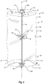
Figure 2 is a perspective view of a container assembly for use with a support housing shown inFigure 1 ; -
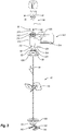
Figure 3 is a partially exploded view of the impeller assembly, drive motor assembly, and drive shaft of the fluid mixing system; -
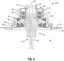
Figure 4 is a cross sectional side view of the first rotational assembly shown inFigure 3 ; -
Figure 5 is a back perspective view of the docking station shown inFigure 1 ; -
Figure 6 is a perspective view of the container assembly shown infigure 2 coupled with the drive motor assembly and yoke shown inFigure 1 ; -
Figure 7 is a bottom perspective view of an alternative embodiment of the support housing shown inFigure 1 with a yolk mounted on the exterior surface of the floor; -
Figure 8 is a perspective view of an alternative embodiment of an impeller assembly that can be used with the container shown inFigure 2 ; -
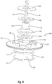
Figure 9 is an exploded view of the lower rotational assembly shown inFigure 8 ; -
Figure 10 is an enlarged perspective view of one of the impellers shown inFigure 8 with the impeller blades in an expanded position. -
Figure 11 is a partially exploded perspective view of the impeller shown inFigure 10 ; -
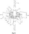
Figure 12 is a perspective view of the impeller shown inFigure 10 with some of the blades in a collapsed position; -
Figure 13 is a perspective view of an alternative embodiment of an impeller having impeller blades with a different configuration; -
Figure 14 is a perspective view of another alternative embodiment of an impeller having different impeller blades; -
Figure 15 is a perspective view of an alternative embodiment of an impeller wherein the flexible drive line is hingedly mounted to the impeller; -
Figure 16 is a perspective view of an alternative embodiment of an impeller wherein the drive line comprises rigid shaft sections that are hingedly mounted to opposing ends of the impeller; -
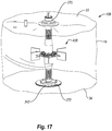
Figure 17 is a perspective view of an alternative embodiment of a container assembly; -
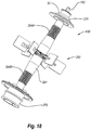
Figure 18 is a perspective view of the impeller assembly shown inFigure 17 ; -
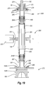
Figure 19 is a cross sectional side view of the impeller assembly shown inFigure 18 ; -
Figure 20 is an elevational front view of an alternative embodiment of a container assembly containing a rigid drive shaft with an impeller having pivotable blades; -
Figure 21 is an elevational front view of an alternative embodiment of an impeller assembly that can be used with a rigid drive shaft; -
Figure 22 is a partial cross sectional front view of an alternative embodiment of a fluid mixing system that includes a container assembly with lateral support assemblies and a support housing; -
Figure 23 is a partially exploded front view of the container assembly shown inFigure 22 ; -
Figure 24 is a cross sectional side view of a retention assembly which forms a portion of the lateral support assembly shown inFigure 22 ; -
Figure 25 is a perspective view of the support housing shown inFigure 22 with support rods exploded therefrom; -
Figure 26 is a perspective view of a locking insert that is disposed on the side of the support housing shown inFigure 25 ; -
Figure 27A is a cross sectional side view of the retention assembly having the support rod partially inserted therein; -
Figure 27B is a cross sectional side view of the retention assembly having the support rod fully inserted and locked therein; -
Figure 28 is a cross sectional side view of a support housing having an alternative embodiment of a container assembly therein when the container assembly includes a rigid drive shaft; -
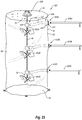
Figure 29 is a cross sectional side view of a support housing having an alternative embodiment of a container assembly therein when the drive line is connected to both the upper end wall and the lower end wall and is supported by lateral support assemblies; and -
Figure 30 is an elevated side view of the container assembly shown inFigure 23 wherein the rotational assembly connected to the drive line has been moved closer to the sidewall of the support housing. - As used in the specification and appended claims, directional terms, such as "top," "bottom," "left," "right," "up," "down," "upper," "lower," "proximal," "distal" and the like are used herein solely to indicate relative directions and are not otherwise intended to limit the scope of the invention or claims.
- The present invention relates to systems and methods for mixing fluids such as solutions or suspensions. The systems can be commonly used as bioreactors or fermentors for culturing cells or microorganisms. By way of example and not by limitation, the inventive systems can be used in culturing bacteria, fungi, algae, plant cells, animal cells, protozoan, nematodes, and the like. The systems can accommodate cells and microorganisms that are aerobic or anaerobic and are adherent or non-adherent. The systems can also be used in association with the formation and/or treatment of solutions and/or suspensions that are for biological purposes, such as media, buffers, or reagents. For example, the systems can be used in the formation of media where sparging is used to control the pH of the media through adjustment of the carbonate/bicarbonate levels with controlled gaseous levels of carbon dioxide. The systems can also be used for mixing powders or other components into a liquid where sparging is not required and/or where the solution/suspension is not for biological purposes.
- Depicted in
Figures 1-3 is one embodiment of aninventive mixing system 10 incorporating features of the present invention. In general, mixingsystem 10 comprises adocking station 12, acontainer station 14 that removably docks withdocking station 12, a container assembly 16 (Figure 2 ) that is supported bycontainer station 14, and a drive shaft 17 (Figure 3 ) that extends betweendocking station 12 andcontainer assembly 16.Container assembly 16 houses the fluid that is mixed. The various components of mixingsystem 10 will now be discussed in greater detail. - As depicted in
Figure 2 ,container assembly 16 comprises acontainer 18 having aside 20 that extends from anupper end 22 to an opposinglower end 24.Upper end 22 terminates at anupper end wall 33 whilelower end 24 terminates at alower end wall 34.Container 18 also has aninterior surface 26 that bounds acompartment 28.Compartment 28 is configured to hold a fluid. In the embodiment depicted,container 18 comprises a flexible bag that is comprised of a flexible, water impermeable material such as a low-density polyethylene or other polymeric sheets or film having a thickness in a range between about 0.1 mm to about 5 mm with about 0.2 mm to about 2 mm being more common. Other thicknesses can also be used. The material can be comprised of a single ply material or can comprise two or more layers which are either sealed together or separated to form a double wall container. Where the layers are sealed together, the material can comprise a laminated or extruded material. The laminated material comprises two or more separately formed layers that are subsequently secured together by an adhesive. Examples of extruded material that can be used in the present invention include the HyQ CX3-9 and HyQ CX5-14 films available from HyClone Laboratories, Inc. out of Logan, Utah. The material can be approved for direct contact with living cells and be capable of maintaining a solution sterile. In such an embodiment, the material can also be sterilizable such as by ionizing radiation. - In one embodiment,
container 18 can comprise a two-dimensional pillow style bag. In another embodiment,container 18 can be formed from a continuous tubular extrusion of polymeric material that is cut to length. The ends can be seamed closed or panels can be sealed over the open ends to form a three-dimensional bag. Three-dimensional bags not only have an annular side wall but also a two dimensional top end wall and a two dimensional bottom end wall. Three dimensional containers can comprise a plurality of discrete panels, typically three or more, and more commonly four or six. Each panel is substantially identical and comprises a portion of the side wall, top end wall, and bottom end wall of the container. Corresponding perimeter edges of each panel are seamed together. The seams are typically formed using methods known in the art such as heat energies, RF energies, sonics, or other sealing energies. - In alternative embodiments, the panels can be formed in a variety of different patterns. Further disclosure with regard to one method of manufacturing three-dimensional bags is disclosed in United States Patent Publication No.
US 2002-0131654 A1, published September 19, 2002 which is incorporated herein by specific reference in its entirety. - It is appreciated that
container 18 can be manufactured to have virtually any desired size, shape, and configuration. For example,container 18 can be formed having a compartment sized to 10 liters, 30 liters, 100 liters, 250 liters, 500 liters, 750 liters, 1,000 liters, 1,500 liters, 3,000 liters, 5,000 liters, 10,000 liters or other desired volumes. The size of the compartment can also be in the range between any two of the above volumes. Althoughcontainer 18 can be any shape, in oneembodiment container 18 is specifically configured to be generally complementary to the chamber oncontainer station 14 in whichcontainer 18 is received so thatcontainer 18 is properly supported within the chamber. - Although in the above discussed
embodiment container 18 is depicted as a flexible bag, in alternative embodiments it is appreciated thatcontainer 18 can comprise any form of collapsible container or semi-rigid container.Container 18 can also be transparent or opaque. - Continuing with
Figure 2 , formed oncontainer 18 are a plurality ofports 30 atupper end 22, a plurality ofports 31 on opposing sides ofside 20 atlower end 24 and aport 32 onlower end wall 34. Each of ports 30-32 communicate withcompartment 28. Although only a few ports 30-32 are shown, it is appreciated thatcontainer 18 can be formed with any desired number of ports 30-32 and that ports 30-32 can be formed at any desired location oncontainer 18. Ports 30-32 can be the same configuration or different configurations and can be used for a variety of different purposes. For example,ports 30 can be coupled with fluid lines for delivering media, cell cultures, and/or other components intocontainer 18 and withdrawing fluid fromcontainer 18.Ports 30 can also be used for delivering gas tocontainer 18, such as through a sparger, and withdrawing gas fromcontainer 18. - Ports 30-32 can also be used for coupling probes and/or sensors to
container 18. For example, whencontainer 18 is used as a bioreactor or fermentor for growing cells or microorganisms, ports 30-32 can be used for coupling probes such as temperatures probes, pH probes, dissolved oxygen probes, and the like. Various optical sensors and other types of sensors can also be attached to ports 30-32. Examples of ports 30-32 and how various probes, sensors, and lines can be coupled thereto is disclosed in United States Patent Publication No.2006-0270036, published November 30, 2006 and United States Patent Publication No.2006-0240546, published October 26, 2006 , which are incorporated herein by specific reference in their entirety. Ports 30-32 can also be used forcoupling container 18 to secondary containers, to condenser systems, and to other desired fittings. -
Container assembly 16 further comprises animpeller assembly 40.Impeller assembly 40 comprises a firstrotational assembly 42A mounted onupper end wall 33, a secondrotational assembly 42B mounted onlower end wall 34, aflexible drive line 44 that extends betweenrotational assemblies impeller 46 coupled to driveline 44. Driveline 44 has alongitudinal axis 48 that extends along the length thereof and can centrally extend therethrough - As depicted in
Figure 4 ,rotational assembly 42A comprises anouter casing 50 having an outwardly projectingannular sealing flange 52 and an outwardly projecting annular mountingflange 53. Ahub 54 is rotatably disposed withinouter casing 50. One or more bearing assemblies 55 can be disposed betweenouter casing 50 andhub 54 to permit free and easy rotation ofhub 54 relative tocasing 50. Likewise, one ormore seals 56 can be formed betweenouter casing 50 andhub 54 so that during use an aseptic seal can be maintained betweenouter casing 50 andhub 54 ashub 54 rotates relative toouter casing 50.Second end 60 ofhub 54 is coupled with afirst end 70 ofdrive line 44. This coupling can be by overmolding, clamp, fastener, or other conventional techniques. Other configurations can also be used. -
Rotational assembly 42A is secured tocontainer 18 so thatsecond end 60 ofhub 54 communicates withcompartment 28. Specifically, in the depictedembodiment container 18 has anopening 74 extending throughupper end wall 33. Sealingflange 52 ofouter casing 50 is sealed, such as by welding or adhesive, around theperimeter bounding opening 74 so thathub 54 communicates withcompartment 28.Flange 52 can be welded on the interior or exterior surface ofcontainer 18. In this configuration,outer casing 50 is fixed tocontainer 18 buthub 54, and thus also driveline 44 andimpeller 46, can freely rotate relative toouter casing 50 andcontainer 18. As a result ofrotational assembly 42A sealing opening 74,compartment 28 is sealed closed so that it can be used in processing sterile fluids. - Turning to
Figure 2 ,rotational assembly 42B can have the same configuration asrotational assembly 42A and can be mounted tolower end wall 34 ofcontainer 18 in the same manner thatrotational assembly 42A is mounted tocontainer 18. Like elements betweenrotational assemblies Second end 72 ofdrive line 44 can be mounted tohub 54 ofrotational assembly 42B in the same way that driveline 44 is connected tohub 54 ofrotational assembly 42A. As will be discussed below in greater detail, a drive shaft is used to engage and rotatehub 54 ofrotational assembly 42A. In the above configuration, a separate drive shaft could also be used to engage and rotatehub 54 ofrotational assembly 42B. In other embodiments,hub 54 ofrotational assembly 42B need not be directly engaged and rotated by a separate drive shaft and thus opening 62 onhub 54 ofrotational assembly 42B can be eliminated. -
Impeller 46 comprises acentral hub 76 having a plurality ofblades 78 radially outwardly projecting therefrom. It is appreciated that a variety of different numbers and configurations ofblades 78 can be mounted onhub 76.Hub 76 can be tubular so thathub 76 is slid overdrive line 44 and then secured in the desired location by crimping, welding, adhesive or using a set screw, clamp, fastener or other securing technique. In other embodiments,hub 76 can comprise two or more separate members that are secured aboutdrive line 44. In yet other embodiments,drive line 44 can comprise two or more separate members where an end of two of the members can be secured using any desired method on opposing ends ofhub 76. Although only oneimpeller 46 is shown, it is appreciated thatimpeller 46 can be positioned at any position alongdrive line 44 and that any number of impellers, such as 2, 3, 4, or more, can be positioned alongdrive line 44. The impellers disclosed herein and the alternatives discussed relative thereto are examples of mixing elements. Mixing elements, however, also include other structures that can be mounted ondrive line 44 that can function to mix fluid when rotated but which would not normally be considered an impeller. - Drive
line 44 can be made from a variety of different flexible materials. By way of example and not be limitation, in oneembodiment drive line 44 can be made from a braded material such as cable, cord or rope. The braded material can be made from strands that are comprised of metal, polymer or other materials that have desired strength and flexibility properties and can be sterilized. For example, the strands can be made from stainless steel. In other embodiments,drive line 44 can be made from a flexible tube, a single solid core line, a linkage, such as a chain or a linkage of universal joints, or other flexible or hinged members. - As depicted in
Figure 3 ,impeller assembly 40 is used in conjunction withdrive shaft 17. Driveshaft 17 has afirst end 84 and an opposingsecond end 86. Formed atfirst end 84 is afrustoconical engaging portion 88 that terminates at acircular plate 90.Notches 92 are formed on the perimeter edge ofcircular plate 90 and are used for engagingdrive shaft 17 with a drive motor assembly as will be discussed below. - Formed at
second end 86 ofdrive shaft 362 isdriver portion 68.Driver portion 68 has a non-circular transverse cross section complementary to engagingportion 66 of hub 54 (Figure 4 ) so that it can facilitate locking engagement within engagingportion 66 ofhub 54. In the embodiment depicted,driver portion 68 has a polygonal transverse cross section. However, other non-circular shapes can also be used. It is also appreciated that other releasable locking mechanisms can be used to engagedrive shaft 362 withhub 54. For example, a bayonet connection, threaded connection, clamp, or fastener could be used. - Returning to
Figure 1 ,container station 14 comprises asupport housing 100 supported on acart 102.Support housing 100 has a substantiallycylindrical sidewall 104 that extends between anupper end 106 and an opposinglower end 108.Lower end 108 has afloor 110 mounted thereto. As a result,support housing 14 has aninterior surface 112 that bounds achamber 114. Anannular lip 116 is formed atupper end 106 and bounds anopening 118 tochamber 114. As discussed above,chamber 114 is configured to receivecontainer assembly 16 so thatcontainer 18 is supported therein. - Although
support housing 100 is shown as having a substantially cylindrical configuration, in alternative embodiments supporthousing 100 can have any desired shape capable of at least partially bounding a compartment. For example,sidewall 104 need not be cylindrical but can have a variety of other transverse, cross sectional configurations such as square, rectangular, polygonal, elliptical, or irregular. Furthermore, it is appreciated thatsupport housing 100 can be scaled to any desired size. For example, it is envisioned thatsupport housing 100 can be sized so thatchamber 114 can hold a volume of less than 50 liters, more than 1,000 liters or any of the other volumes or range of volumes as discussed above with regard tocontainer 18.Support housing 100 is typically made of metal, such as stainless steel, but can also be made of other materials capable of withstanding the applied loads of the present invention. - With continued reference to
Figure 1 ,sidewall 104 ofsupport housing 100 has anenlarged access 120 atlower end 108 so as to extend throughsidewall 104. Adoor 122 is hingedly mounted tosidewall 104 and can selectively pivot to open andclose access 120. Alatch assembly 124 is used to lockdoor 122 in the closed position. Anopening 126, which is depicted in the form of an elongated slot, extends throughdoor 122.Opening 126 is configured to align with ports 31 (Figure 2 ) ofcontainer assembly 16 whencontainer assembly 16 is received withinchamber 114 so thatports 31 project into or can otherwise be accessed throughopening 126. In some embodiments, a line for carrying fluid or gas will be couple withport 31 and can extend out ofchamber 114 throughopening 126. As previously mentioned, any number ofports 31 can be formed oncontainer 18 and thus any number of separated lines may pass out throughopening 126 or through other openings formed onsupport housing 100. Alternatively, different types of probes, inserts, connectors, or the like may be coupled withports 31 which can be accessed throughopening 126 or other openings. - In one embodiment of the present invention means are provided for regulating the temperature of the fluid that is contained within
container 18 whencontainer 18 is disposed withinsupport housing 100. By way of example and not by limitation,sidewall 104 can be jacketed so as to bound one or more fluid channels that encirclesidewall 104 and that communicate with aninlet port 130 and anoutlet port 132. A fluid, such as water or propylene glycol, can be pumped into the fluid channel throughinlet port 130. The fluid then flows in a pattern aroundsidewall 104 and then exits out throughoutlet port 132. - By heating or otherwise controlling the temperature of the fluid that is passed into the fluid channel, the temperature of
support housing 100 can be regulated which in turn regulates the temperature of the fluid withincontainer 18 whencontainer 18 is disposed withinsupport housing 100. In an alternative embodiment, electrical heating elements can be mounted on or withinsupport housing 100. The heat from the heating elements is transferred either directly or indirectly tocontainer 18. Alternatively, other conventional means can also be used such as by applying gas burners to supporthousing 100 or pumping the fluid out ofcontainer 18, heating the fluid and then pumping the fluid back intocontainer 18. When usingcontainer 18 as part of a bioreactor or fermentor, the means for heating can be used to heat the culture withincontainer 18 to a temperature in a range between about 30° C to about 40° C. Other temperatures can also be used. - As will be discussed below in greater detail, a
yoke 140 is centrally mounted on the interior surface offloor 110 ofsupport housing 100.Yoke 140 has aU-shaped slot 142 that is bounded by an inwardly projectingU-shaped catch lip 144.Yoke 140 is configured so that whencontainer assembly 16 is received withinchamber 114 ofsupport housing 100, secondrotational assembly 42B can be manually slid into slot 142 (Figure 3 ) so that mountingflange 53 of secondrotational assembly 42B is captured withinslot 142 belowcatch lip 144, thereby securing secondrotational assembly 42B toyoke 140 and preventingrotational assembly 42B from being raised vertically relative toyoke 140. It is appreciated that the function ofyoke 140 is to releasably engage secondrotational assembly 42B and as such,yoke 140 can be in the form of a variety of different slots, clamps, ties, fasteners or the like. It is likewise appreciated that secondrotational assembly 42B can be attached toyoke 140 by reaching in throughaccess 120 onsidewall 104 ofsupport housing 100. - As depicted in
Figure 1 ,docking station 12 comprises astand 134, anadjustable arm assembly 136 coupled to stand 134 and adrive motor assembly 300 mounted onarm assembly 136. Drivemotor assembly 300 is used in conjunction with drive shaft 17 (Figure 3 ) and can be used for mixing and/or suspending a culture, solution, suspension, or other liquid within container 18 (Figure 2 ). Turning toFigure 3 , drivemotor assembly 300 comprises ahousing 304 having afront face 305 that extends from atop surface 306 to an opposingbottom surface 308. Anopening 310 extends throughhousing 304 fromtop surface 306 tobottom surface 308. Atubular motor mount 312 is rotatably secured within opening 310 ofhousing 304. Upstanding frommotor mount 312 is alocking pin 316. Adrive motor 314 is mounted tohousing 304 and engages withmotor mount 312 so as to facilitate select rotation ofmotor mount 312 relative tohousing 304. Driveshaft 17 is configured to pass throughmotor mount 312 so that engagingportion 88 ofdrive shaft 17 is retained withinmotor mount 312 and lockingpin 316 ofmotor mount 312 is received withinnotch 92 ofdrive shaft 17. As a result, rotation ofmotor mount 312 bydrive motor 314 facilitates rotation ofdrive shaft 17. Further discussion ofdrive motor assembly 300 and how it engages withdrive shaft 17 and alternative designs ofdrive motor assembly 300 are discussed inUS Patent Publication No. 2011/0188928, published August 4, 2011 which is incorporated herein in its entirety by specific reference. -
Arm assembly 136 is used to adjust the position ofdrive motor assembly 300 and thereby also adjust the position ofdrive shaft 17. As depicted inFigure 5 ,arm assembly 136 comprises afirst arm 320 mounted to stand 134 that vertically raises and lowers, asecond arm 322 mounted to thefirst arm 320 that slides horizontally back and forth, and athird arm 324 mounted tosecond arm 322 that rotates about ahorizontal axis 326. Drivemotor assembly 300 is mounted tothird arm 324. Accordingly, by movements ofarms motor assembly 300 can be positioned in any desired location or orientation relative to supporthousing 100 andcontainer assembly 16. For example, drivemotor assembly 300 can be positioned so thatdrive shaft 17 is centered and vertically oriented when connected withcontainer assembly 16. In other embodiments, driveshaft 17 can be oriented at an angle, such as in a range between 10° to 30° from vertical when connected withcontainer assembly 16. Further discussion and alternative embodiments with regard todocking station 12,arm assembly 136, andcontainer station 14 is provided inUS Patent Publication No. 2011/0310696, published December 22, 2011 , which is incorporated herein in its entirety by specific reference. - During use,
container station 14 anddocking station 12 are removably coupled together as shown inFigure 1 . One example of howdocking station 12 andcontainer assembly 16 can be coupled together is disclosed inUS Patent Publication No. 2011/0310696 which was previously incorporated by reference. Other methods can also be used. Either before or after coupling togethercontainer station 14 anddocking station 12,container assembly 16 is positioned withinchamber 114 ofsupport housing 100 and secondrotational assembly 42B is secured toyoke 140 as discussed above. - In this position,
arm assembly 136 is used to properly positiondrive motor assembly 300 so that firstrotational assembly 42A can be coupled withdrive motor assembly 300. Specifically, as depicted inFigure 3 ,housing 304 ofdrive motor assembly 300 has aU-shaped receiving slot 330 that is recessed on afront face 305 andbottom surface 308 so as to communicate withopening 310 extending throughhousing 304. Receivingslot 330 is bounded by aninside face 332 on which aU-shaped catch slot 334 is recessed. As shown inFigure 1 , adoor 336 is hingedly mounted tohousing 304 and selectively closes the opening to receivingslot 330 fromfront face 305. As depicted inFigure 3 , to facilitate attachment ofrotational assembly 42A tohousing 304, withdoor 336 rotated to an open position,rotational assembly 42A is horizontally slid into receivingslot 330 fromfront face 305 ofhousing 304 so that mountingflange 53 that is radially outwardly extending from the upper end ofrotational assembly 42A is received and secured withincatch slot 334. Firstrotational assembly 42A is advanced into receivingslot 330 so that opening 62 ofrotational assembly 42A aligns with the passage extending throughmotor mount 312. Door 336 (Figure 1 ) is then moved to the closed position and secured in place by a latch or other locking mechanism so that firstrotational assembly 42A is locked to drivemotor assembly 300. -
Rotational assemblies motor assembly 300 andyoke 140, respectively, as shown inFigure 6 . Arm assembly 136 (Figure 5 ) can now be used to remove any slack from or to tensionflexible drive line 44 by raisingdrive motor assembly 300 to whichrotational assembly 42A is coupled. Likewise,arm assembly 136 can be used to adjust the orientation ofdrive line 44. For example, by adjusting the position ofdrive motor assembly 300,drive line 44 can be adjusted so as to be centered withinsupport housing 100 and vertically oriented or driveline 44 can be oriented at an angle, such as in a range between 10° to 30° from vertical. Other positions and orientations can also be used. - Once first
rotational assembly 42A is secured to drivemotor assembly 300, driveshaft 17 can be advanced down throughmotor mount 312 ofdrive motor assembly 300 and into opening 62 ofrotational assembly 42A so thatdrive shaft 17 engages withhub 54. Fluid and other components can be delivered intocontainer 18.Drive motor 324 can be activated so as to rotatedrive shaft 17 which in turn begins to rotatehub 54,drive line 44 andimpeller 46. Wherecontainer 18 is functioning as a bioreactor or fermentor, cells or microorganisms along with nutrients and other standard components can be added tocontainer 18. Rotation ofimpeller 46 facilitates mixing and/or suspension of the fluid and components contained withincontainer 18. Where driveline 44 is made of a material that flexes under torsion, such as a flexible cable, cord, solid core line or the like, driveline 44 will typically be able to axially twist along the length thereof. That is,first end 70 will begin to rotate concurrently with the rotation ofhub 54 of firstrotational assembly 42A butsecond end 72 andhub 54 of secondrotational assembly 42A will not begin to rotate untildrive line 44 has sufficiently twisted along its length so thatsecond end 72 produces a torsion force onhub 54 of secondrotational assembly 42A sufficient to overcome the frictional resistance onhub 54.Impeller 46 also produces resistance against the fluid withincontainer 18 which results in twisting ofdrive line 44 during rotation. In other embodiments, such as wheredrive line 44 is a type of linkage, axle twisting ofdrive line 44 may be negligible. - In one embodiment, at least a portion of
drive line 44 is sufficiently flexible so that the flexible portion ofdrive line 44 can be twisted under torsion aboutlongitudinal axis 48 ofdrive line 44 over an angle of at least 15°, 25°, 45°, 90°, 180°, 360°, 720° or more without elastic deformation ofdrive line 44. In other embodiments, at least a portion ofdrive line 44 is sufficiently flexible so that the flexible portion ofdrive line 44 can be bent or folded relative to a linear longitudinal axis 48 (Figure 2 ) ofdrive line 44 over an angle α (Figure 3 ) of at least 15°, 25°, 45°, 90°, 135°, 180° or more without elastic deformation ofdrive line 44. Expressed in other terms,drive line 44 or the flexible portion ofdrive line 44 can have a bend radius wrapped 180° without elastic deformation in a range between about 2 cm to about 100 cm with about 6 cm to about 80 cm, about 10 cm to about 60 cm, or about 10 cm to about 40 cm being more common. Other flexibilities can also be used. It is appreciated that the entire length ofdrive line 44 need not be flexible. For example, a percentage of the entire length ofdrive shaft 44, such as at least or not to exceed 30%, 40%, 50%, 60%, 70%, 80% or more ofdrive shaft 44, could be flexible while the remainder is rigid or at least more rigid. - In an alternative method of use as previously mentioned, a second drive shaft could be coupled with
hub 54 of secondrotational assembly 42B though a hole formed infloor 110 ofsupport housing 100. In this embodiment, both ends 70 and 72 ofdrive line 44 could be concurrently rotated although there may still be some twisting ofdrive line 44 along a central length or adjacent toimpeller 46. - In mixing
system 10,docking station 12 is used which includesarm assembly 136. In this design,docking station 12 can be coupled with any number ofdifferent container stations 14 having acontainer assembly 16 therein. In an alternative embodiment, however,docking station 12 can be eliminated andarm assembly 136 can be mounted directly ontosupport housing 100. Alternative examples of arm assembles and how they can be mounted ontosupport housing 100 is disclosed inUS Patent Application No. 13/659,616, filed October 24, 2012 - In the above discussed embodiment depicted in
Figure 1 ,yoke 140 is mounted on the interior surface offloor 110 ofsupport housing 100 for engaging with secondrotational assembly 42B (Figure 2 ). In an alternative embodiment as depicted inFigure 7 . Ayoke 140A can be mounted on the exterior surface offloor 110 ofsupport housing 100. Ahole 148 centrally extends throughfloor 100 so as to communicate withchamber 114. In this embodiment,yoke 140A has anopening 149 that is bounded between abody 150 and alocking arm 152 hingedly mounted thereto. During use, with lockingarm 152 in an open position, the free end of secondrotational assembly 42B (Figure 2 ) is passed down throughhole 148 so as to be received withinopening 149. Lockingarm 152 is then moved to the closed position, as shown inFigure 7 , and secured in place by alatch 154. In this configuration, the end of secondrotational assembly 42B is secured toyoke 140A. It is appreciated thatyokes housing 100 but can be located on a separate structure at a position belowsupport housing 100. Secondrotational assembly 42B can be configured to pass down throughhole 148 and engage with the yoke. - In one embodiment of the present invention, means are provided for holding the
lower end 24 ofcontainer 18 stationary whileflexible drive line 44 is rotated withincompartment 28 ofcontainer 18. Examples of this means includesyoke 140 mounted on the interior surface offloor 110,yoke 140A mounted on the exterior surface offloor 110 andyoke 140A mounted on a separate structure located belowfloor 110. - Depicted in
Figure 8 is an alternative embodiment of animpeller assembly 40A. Like elements betweenimpeller assemblies Impeller assembly 40A comprises a first rotational assembly 160A and a secondrotational assembly 160B withdrive line 44 extending therebetween. First rotational assembly 160A has substantially the same configuration as firstrotational assembly 42A and includesouter casing 50 having sealingflange 52 for securing tocontainer 18 and mountingflange 53. First rotational assembly 160A has ahub 162 that rotates relative tocasing 50. However, in contrast to having an opening 62 (Figure 4 ) located at the end thereof,hub 162 includes an outwardly projectingstem 164.Stem 164 has a non-circular transverse cross section, such as polygonal, so that a drive shaft 17A having acomplementary socket 166, that replaces driver portion 68 (Figure 3 ), can securely engage with and rotatehub 162. - As depicted in
Figure 9 , secondrotational assembly 160B comprises anouter casing 168 that includes acylindrical base 170 having one or more mountingflanges 171 radially outwardly projecting from a lower end thereof and an enlargedannular sealing flange 172 radially outwardly projecting from the upper end thereof.Base 170 and mountingflanges 171 are configured to be engaged byyoke 140A (Figure 8 ). Sealingflange 172 is configured to secure tocontainer 18, such as by welding, in the same manner as sealing flange 52 (Figure 2 ).Outer casing 168 has atop surface 174 on which a cylindricalblind pocket 176 is formed. - Second
rotational assembly 160B also includes ahub 178 having a base 180 to whichsecond end 72 ofdrive line 44 is secured.Hub 178 also includes anannular flange 182 encircling and radially outwardly projecting from a lower end ofbase 180.Flange 182 is configured so that it can be rotatably received withinblind pocket 176.Annular bearings pocket 176 on opposing sides of flange 184 so thathub 178 can freely rotate relative toouter casing 168. Acover plate 186 encircleshub 178 and/or driveline 44 and is positioned over bearing 184A.Cover plate 186 is secured in place by engaging with lockingfingers 188 that project fromtop surface 174 at spaced apart locations aroundpocket 176. In this configuration,cover plate 186 retainshub 178 withinouter casing 168. It is appreciated that becausepocket 176 is blind, it is not necessary to position a seal betweenhub 178 andouter casing 168, although a seal can be used if desired. It is also appreciated that the rotational assemblies can have a variety of other configurations. - Returning to
Figure 8 , disposed at an upper end ofdrive line 44 is afoam breaker 156.Foam breaker 156 includes ahub 157 secured to driveline 44 and abar 158 that outwardly projects from opposing sides ofhub 157.Foam breaker 156 rotates concurrently withdrive line 44 to break up foam that is formed at the upper end ofcontainer 18. It is appreciated thatfoam breaker 156 can come in a variety of different configurations. - Also disposed along
drive line 44 are a plurality of spaced apartimpellers 190A-D. As depicted inFigure 10 , eachimpeller 190 comprises atubular hub 192 which can be advanced overdrive line 44 and secured in place such as by crimping, clamp, fastener, welding, set screw or the like. As depicted inFigure 11 , aflange 194 encircles and radially outwardly projects fromhub 192.Flange 194 has afirst side face 196 and an opposingsecond side face 198 with a plurality of openings 200A extending therethrough adjacent to a perimeter edge offlange 194. Outwardly projecting fromfirst side face 196 are a plurality of spaced apart stops 202 with eachstop 202 being disposed adjacent to a corresponding opening 200A. Outwardly projecting from the end of eachstop 202 is a key 204. -
Impeller 190 also includes a plurality ofblades 206. Eachblade 206 comprises of anelongated arm 208 having anenlarged blade head 210 located at one end and anaxle 212 disposed at the opposing end.Axle 212 has afirst end 214 and an opposingsecond end 216 that project from opposing sides ofarm 208.First end 214 ofaxle 212 is configured to be received within a corresponding opening 200A so thataxle 212 can rotate within opening 200A. Anannular retainer 220 has acentral passage 222 through whichhub 192 can be advanced. A plurality of spaced apartopenings 200B that are sized to receivesecond end 216 ofaxle 212 extend between opposing sides ofretainer 220. A plurality of spaced apartkeyways 224 are recessed on an outer edge ofretainer 220.Retainer 220 is configured to be advanced overhub 192 so that each key 204 is received within a correspondingkeyway 224, andsecond end 216 of eachaxle 212 is received within acorresponding opening 200B.Retainer 220 can be secured tokeys 204 such as by press fit connection, adhesive, welding, fasteners, or the like.Hub 192,flange 194 andretainer 220 combine to form an impeller body to whichblades 206 are attached. - In the assembled configuration,
axle 212 is free to rotate withinopenings 200A and 200B so thatblades 206 are movable between a collapsed position, such as where ablade 206A is folded towardflange 194 inFigure 12 , and an extended position, such as whereblade 206A is folded away fromflange 194 inFigure 11 . In the extended position,arm 208 hits againststop 202 to prevent further rotation away from the collapsed position.Blades 206 typically radially outwardly project fromhub 102 when in the extended position but can project at angles relative tohub 102. In most embodiments, however, anouter tip 223 ofblades 206 is spaced farther fromhub 192 when in the extended position than when in the collapsed position. - In alternative embodiments, it is appreciated that there are a wide variety of different ways in which
blades 206 can be rotatable connected tohub 192. For example,axles 212 could be rigidly fixed toflange 194 and/orretainer 220.Arms 208 could then pivot aboutaxles 212. In another embodiment,axles 212 could be hingedly secured toflange 194 so as to eliminate the need forretainer 220. In addition, bothflange 194 andretainer 220 could be integrally formed as a unitary member withhub 192 andblades 206 could be snap fit or otherwise secured therebetween. Other alternatives also exist. - During sterilization, transport, storage, and at other times, in can be desirable to fold up or roll up
container 18 into a more compact structure so that it is easier to handle and occupies less space. By makingdrive line 44 out of a flexible material, this enables driveline 44 to be concurrently folded up or rolled up withcontainer 18. Use of the flexible drive line also eliminates the need for an elongated drive shaft which can be expensive to make and difficult to attach, particularly in low ceiling environments. Furthermore, by makingblades 206 movable between the collapsed and extended position, some or all of the blades can be moved to the collapsed position during the folding or rolling up ofcontainer 18. Collapsing of the blades enablescontainer 18 to be folded smaller, helps preventsblades 206 from puncturingcontainer 18 and can result in less stress being placed onblade 206. However, as will be discuss below in greater detail, as eachimpeller 190 is rotated within the fluid contained withincontainer 18, each ofblades 206 catch the fluid and automatically move to the expanded position which is a more optimal position for mixing the fluid. - Another benefit of the
inventive impeller 190 is that it is a modular system that can be used within a variety of different blade configurations. For example, in the embodiment depicted inFigure 10 , eachblade 206 has ablade head 210 having a generally flat rectangular configuration. This configuration of blade is commonly referred to as a Rushton blade. Depicted inFigure 13 is animpeller 225 with like elements betweenimpeller 190 andimpeller 225 being identified by like reference characters. The only difference betweenimpellers impeller 225,blades 206 have been replaced withblades 226.Blades 226 includearm 208 andaxle 212 but in contrast to having a flatrectangular blade head 210, they have ablade head 228 having a curved surface. More specifically,blade head 228 has a length with an arched or substantially semi-circular transverse cross section along the length. Again, each ofblades 226 can be moved from a collapsed position to an extended position. Depicted inFigure 14 is still another embodiment of animpeller 230 havingfoldable blades 232 with ablade head 234 that slopes relative to the longitudinal axis ofhub 192. - In each of
impellers - Depicted in
Figure 15 is an alternative embodiment of animpeller 238 that is hingedly mounted to driveline 44. Like elements betweenimpellers Impeller 238 is substantially identical toimpeller 190 except that in contrast to hub 192 (Figure 10 ) which is tubular and received overdrive line 44,impeller 238 includes anelongated hub 240 having afirst end 242 with a U-shaped connecter 244A formed thereat and an opposingsecond end 246 with aU-shape connector 244B formed thereat. Each of connectors 244A and B bound aslot 248 and have anopening 250 transversely extending therethrough.Flexible line 44 is comprised ofline portion 252A having connector 254A mounted on the end thereof andline portion 252B having aconnector 254B mounted on the end thereof. Each of connecters 254A and B also have anopening 256 transversely extending therethrough. During assembly, connectors 254A and B are received withinslots 248 of U-shaped connectors 244A and B, respectively, so thatopenings openings impeller 238. Hinge pins 258 can be attached to connectors 244A and B by being press fit, welded, threaded or using other conventional techniques. In alternative embodiments, it is appreciated that a variety of different unions, hinges, swivels, and the like can be used to hingedly connectline portions 252A and B to opposing ends ofhub 240. Furthermore, althoughimpeller 238 is shown having pivotably mountedblades 206, in analternative embodiment impeller 238 can be formed with fixed blades. -
Figure 16 again depictsimpeller 238. However in contrast to being hingedly coupled toflexible drive line 44,impeller 238 inFigure 16 is hingedly coupled toline portions 262A and B of arigid drive line 264. That is,line portions 262A and B can haveopenings 256 extending therethrough and can be made of shafts, rods or tubes or the like that are comprised of or consist of metal, plastics, composites, or the like that are substantially rigid or have limited flexibility. For example,line portions 262A and B can have a bend radius wrapped 90° that must be greater than 8 meters, 10 meters or 12 meters to prevent elastic deformation. - Depicted in
Figure 17 is a perspective view of an alternative embodiment of acontainer assembly 16B that includes an alternative embodiment of a flexible drive line.Container assembly 16B can be operated within support housing 100 (Figure 1 ) in substantially the same manner as the other container assemblies discussed herein. Specifically,container assembly 16B comprisescontainer 18 having animpeller assembly 40B coupled thereto.Impeller assembly 40B comprises a firstrotational assembly 270 mounted toupper end wall 33 ofcontainer 18 and a secondrotational assembly 242 mounted tolower end wall 34 ofcontainer 18. As depicted inFigures 18 and19 , upperrotational assembly 270 comprisesouter casing 50 andhub 162 as previously discussed.Various bearing assemblies 274 can be positioned betweenouter casing 50 andhub 162 to facilitate ease of rotation ofhub 162. One ormore seals 276 can also be positioned betweenouter casing 50 andhub 162 to form a liquid-tight seal therebetween. Anadapter 278 is coupled withhub 162 and has astem 280 that projects away fromhub 162. In an alternative embodiment, stem 280 can be integrally formed as a unitary structure withhub 162. - Second
rotational assembly 272 includesouter casing 168,bearings 184A and B andcover plate 186 as previously discussed. Secondrotational assembly 272 also includes ahub 284 having an upwardly extendingstem 286 that passes throughcover plate 186 and an outwardly projectingflange 288 that is positioned betweenbearings 184A and B. Located betweenrotational assemblies impeller 290.Impeller 290 comprises atubular hub 291 having afirst end 292 and an opposingsecond end 293.Flange 194 encircles and radially outwardly projects fromhub 291.Blades 206 hingedly mounted betweenflange 194 andretainer 220 as previously discussed. In an alternative embodiment, fixed blades can be secured tohub 291 orflange 194. - Drive
line assembly 40B also includes aflexible drive line 44B that includes adrive line portion 294A and adrive line portion 294B. Each of drive line portions 294 comprise a flexible tube that can be made of a resiliently flexible plastic or other material. In the depicted embodiments, although not required, the tubes are corrugated so as to increase flexibility. Drive line portions 294 can have the same flexibility asdrive line 44 as previously discussed. Driveline portion 294A has afirst end 295 that is received over and coupled to stem 280 and an opposingsecond end 296 that is received within and secured tofirst end 292 ofhub 291. Similarly driveline portion 294B has afirst end 297 received over and secured to stem 286 and an opposingsecond end 298 received within and secured tosecond end 293 ofhub 291. In this configuration, rotation ofhub 162 of firstrotational assembly 270 facilitates rotation ofdrive line portions 294A and B,impeller 290, andhub 284 of secondrotational assembly 272. - Although the above discussed embodiments primarily disclose the use of impellers having pivotable blades with flexible drive lines, it is appreciated that the inventive impellers of the present invention can also be used with rigid drive shafts. For example, depicted in
Figure 20 is a container assembly 16C that includecontainer 18. Adynamic seal 350 is mounted onupper end wall 33. Arigid drive shaft 352 passes throughdynamic seal 350 and has afirst end 354 disposed outside ofcontainer 18 and an opposingsecond end 356 disposed withincontainer 18.Dynamic seal 350 enablesdrive shaft 352 to freely rotate relative tocontainer 18 while forming an aseptic seal betweencontainer 18 and driveshaft 352. Adriver portion 358, which can have a polygonal or other non circular transverse cross section or some other engaging surface, can be formed atfirst end 354 so that a drive motor can engage with and rotatedrive shaft 352. - Mounted on
second end 356 ofdrive shaft 352 isimpeller 190 as previously discussed herein. Rotation ofdrive shaft 356 causesblades 206 to move to the expanded position and mix the fluid withincontainer 18.Impeller 190 can be replaced with the other impellers discussed herein having pivotable blades and can incorporate other alternative configurations as discussed herein. Again, as a result ofpivotable blades 206,container 18 can be more fully collapsed aroundimpeller 190 while minimizing risk of damage tocontainer 18 and toblades 206. - Depicted in
Figure 21 is another alternative embodiment of mixing system that incorporates an impeller with pivotable or foldable blades. The mixing system includes animpeller assembly 40C that comprises an elongatedtubular connector 542 having arotational assembly 548 mounted at one end and animpeller 564 or other mixing element mounted on the opposing end. More specifically,tubular connector 542 has afirst end 544 and an opposingsecond end 546 with apassage 549 that extends therebetween. In one embodiment,tubular connector 542 comprises a flexible tube, such as a polymeric tube, having the same flexibility as discussed above with regard to driveline 44. As such,tubular connector 542 can comprise a flexible drive line as claimed herein. In other embodiments,tubular connector 542 can comprise a rigid tube or other tubular structure. -
Rotational assembly 548 is mounted tofirst end 544 oftubular connector 542.Rotational assembly 548 comprisesouter casing 50 having an outwardly projectingannular sealing flange 52 and an outwardly projecting mountingflange 53 as previously discussed. Atubular hub 454 is rotatably disposed withinouter casing 50. One or more bearing assemblies, as previously discussed, can be disposed betweenouter casing 50 andhub 554 to permit free and easy rotation ofhub 554 relative tocasing 50. Likewise, one or more seals, as previously discussed, can be formed betweenouter casing 50 andhub 554 so that during use an aseptic seal can be maintained betweenouter casing 50 andhub 554. -
Hub 554 has aninterior surface 556 that bounds anopening 558 extending therethrough.Interior surface 556 includes an engaging portion having a polygonal or other non-circular transverse cross section so thatdriver portion 68 ofdrive shaft 362, as also shown inFigure 21 , passing throughopening 558 can engage the engaging portion and facilitate rotation ofhub 554 by rotation ofdrive shaft 362.Hub 554 can also comprise atubular stem 560 projecting away fromouter casing 50.Hub 554 can couple withfirst end 544 oftubular connector 542 bystem 560 being received withinfirst end 544. A pull tie, clamp, crimp or other fastener can then be used to furthersecure stem 560 to tubular connect 542 so that a liquid tight seal is formed therebetween. Other conventional connecting techniques can also be used. -
Impeller 564 comprises acentral hub 566 havingblades 206 pivotably coupled thereto through the use offlange 194 andretainer 220 as previously discussed with regard toFigure 11 . Alternative embodiments as discussed herein with regard to other impellers having pivotable blades can also be incorporated intoimpeller 564.Hub 566 has afirst end 570 with ablind socket 572 formed thereat.Socket 572 typically has a noncircular transverse cross section, such as polygonal, so that it can engage adriver portion 378 ofdrive shaft 362. Accordingly, whendriver portion 378 is received withinsocket 572,driver portion 378 engages withimpeller 564 such that rotation ofdrive shaft 362 facilities rotation ofimpeller 564. -
Impeller 564 can be attached toconnector 542 by insertingfirst end 570 ofhub 566 withinconnector 542 atsecond end 546. A pull tie, clamp, crimp, or other type of fastener can then be cinched aroundsecond end 546 ofconnector 542 so as to form a liquid tight sealed engagement betweenimpeller 564 andconnector 542. -
Rotational assembly 548 is secured tocontainer 18 in substantially the same manner that rotational assembly 42 was secured tocontainer 18, as previously discussed with regard toFigure 2 , so thattubular connector 542 andimpeller 564 extend into or are disposed withincompartment 28 ofcontainer 18. - In
general drive shaft 362 comprises ahead section 364 and ashaft section 366 that can be coupled together by threaded connection or other techniques.Head section 364 has substantially the same configuration asdrive shaft 17 discussed with regard toFigure 3 and thus likefeatures head section 364 and driveshaft 17 will be identified by like reference characters. Alternatively, driveshaft 362 can be formed as a single piece member or from a plurality of attachable sections. Driveshaft 362 has afirst end 368 and an opposingsecond end 370. Formed atfirst end 368 is afrustoconical engaging portion 88 as previously discussed with regard toFigure 3 . Formed atsecond end 370 ofdrive shaft 362 isdriver portion 378.Driver portion 378 has a non-circular transverse cross section so that it can facilitate locking engagement withinhub 466 ofimpeller 464. In the embodiment depicted,driver portion 378 has a polygonal transverse cross section. However, other non-circular shapes can also be used.Driver portion 68 is also formed alongdrive shaft 362 towardfirst end 368.Driver portion 68 also has a non-circular transverse cross section and is positioned so that it can facilitate locking engagement within the engaging portion ofrotational assembly 448. - During use,
container 18 havingimpeller assembly 40C coupled thereto is received within support housing 100 (Figure 1 ) and rotational assembly is secured to drivemotor assembly 300 as previously discussed with regard toFigure 3 . Driveshaft 362 is advanced down throughmotor mount 312,hub 454 ofrotational assembly 548,tubular connecter 542 and intohub 566 ofimpeller 564. As a result of the interlocking engagement ofdriver portions hubs drive shaft 362 bydrive motor assembly 300 facilitates rotation ofhub 554,tubular connecter 542 andimpeller 564 relative toouter casing 50 ofrotational assembly 548 andcontainer 18. The rotation ofimpeller 564causes blades 206 to move to the expanded position and mix the fluid withincontainer 18. - It is appreciated that
impeller assembly 40C,drive shaft 362 and the discrete components thereof can have a variety of different configuration and can be made of a variety of different materials. Alternative embodiments of and further disclosure with respect toimpeller assembly 40C,drive shaft 362, and the components thereof are disclosed inUS Patent No. 7,384,783, issued June 10, 2008 andUS Patent Publication No. 2011/0188928, published August 4, 2011 which are incorporated herein in their entirety by specific reference. - In the prior discussed embodiments incorporating the flexible drive line, the flexible drive line is supported by being secured to both the upper end wall and lower end wall of the container. In an alternative embodiment, the flexible drive line can be supported and stabilized by being secured to the upper end wall of the container and at one or more locations along the length of the flexible drive line. For example, depicted in
Figure 22 is an alternative embodiment of afluid mixing system 10A incorporating features of the present invention.Fluid mixing system 10A comprises acontainer assembly 16D at least partially disposed within the compartment of asupport housing 100A. Like elements betweencontainer assembly 16 and 16A and betweensupport housing container 16 andsupport housing 100 are also applicable to corresponding elements of container assembly 16A and supporthousing 100A. - As depicted in
Figure 23 , container assembly 16A comprisescontainer 18 havingflexible drive line 44 disposed therein. First end 70 offlexible drive line 44 is secured toupper end wall 33 ofcontainer 18 byrotational assembly 42A. Mounted onflexible drive line 44 as spaced apart locations are mixingelements 400A-C. Each of mixingelement 400A-C can comprise a fixed blade impeller, such as previously discussedimpeller 46, a foldable impeller, such as previously discussedimpellers more mixing elements 400. In contrast tocontainer assembly 16 wheresecond end 72 ofdrive line 44 is secured tolower end wall 34, container assembly 16A hassecond end 72 ofdrive line 44 suspended abovelower end wall 34. - To stabilize
drive line 44 withincompartment 28 ofcontainer 18, container assembly 16A compriseslateral support assemblies 402A-C coupled withflexible drive line 44 at space apart locations along the length thereof. Eachlateral support assembly 402A-C comprises a retention assembly 404 having afirst end 405 secured toside 20 ofcontainer 18 and an opposingsecond end 407 secured toflexible drive line 44. Lateral support assembly 402 also includes asupport rod 406 that is selectively received and secured within corresponding retention assembly 404. Each retention assembly 404 comprises a port fitting 410 atfirst end 405 that is coupled withside 20 ofcontainer 18, areceiver 408 atsecond end 407 that is mounted toflexible drive line 44, and aflexible tube 412 that extends between port fitting 410 andreceiver 408. - As depicted in
Figure 24 ,receiver 408 comprises aninner housing 414 that is securely fixed toflexible drive line 44 such as by crimping, adhesive, clamps, fasteners, or the like.Receiver 408 also includes anouter housing 416 that encirclesinner housing 414. Abearing 418, such as a ball thrust bearing, roller thrust bearing, or other type of bearing, is disposed betweeninner housing 414 andouter housing 416. Bearing 418 enablesinner housing 414 and driveline 44 to rotate concurrently relative toouter housing 416.Outer housing 416 includes abody 420 having atubular stem 422 outwardly projecting therefrom.Stem 422 can be integrally formed with or secured tobody 420. Anannular barb 423 can encircle and outwardly project on the end ofstem 422 for engaging withflexible tube 412.Stem 422 has aninterior surface 424 that bounds anopening 426 that can extend intobody 420. Formed oninterior surface 424 ofstem 422 and/orbody 420 is anengaging thread 428. - As also depicted in
Figure 24 , port fitting 410 comprises atubular stem 430 having afirst end 432 and an opposingsecond end 434. Anannular barb 436 can encircle and outwardly extending fromsecond end 434 for engaging withflexible tube 412. Radially outwardly projecting fromfirst end 432 is aretention flange 438. As will be discussed below in greater detail,retention flange 438 is used to secure port fitting 410 torigid support housing 100.Retention flange 438 need not encircle stem 430 and can have a variety of different configurations. Encircling and radially outwardly projecting fromstem 430 at a location between opposing ends 432 and 434 is a mountingflange 440. Mountingflange 440 is welded or otherwise secured toside 20 ofcontainer 18 so as to form a liquid tight seal therewith. As a result,first end 432 of port fitting 410 disposed outside ofcontainer 18 whilesecond end 434 is disposed withincontainer 18.Stem 430 has aninterior surface 442 that bounds apassageway 444 extending therethrough. -
Flexible tube 412 can comprise any type of flexible tube, tubing, hose, pipe or the like and is typically comprised of an elastomeric polymer. By makingtube 412 flexible,tube 412 can be folded or rolled when collapsingcontainer 18 for shipping, storage, disposal or the like. In an alternative embodiment it is appreciated thattube 412 need not be flexible but can be rigid or semi-rigid.Tube 412 has aninterior surface 446 that bounds apassageway 448 that longitudinally extends throughtube 412 from afirst end 450 to an opposingsecond end 452.First end 450 oftube 412 is advanced overstem 430 of port fitting 410 so as to form a liquid tight seal therewith whilesecond end 452 oftube 412 is received overstem 422 ofreceiver 408 so as to form a liquid type seal therewith. Afastener 454 such as a pull tie, crimp, clamp, or similar structure can be secured aroundfirst end 450 andsecond end 452 so as to secure the engagement betweentube 412 and stems 422 and 430. - During use, as depicted in
Figure 22 ,container assembly 16D is received withinchamber 114 ofsupport housing 100A.Support housing 100A is substantially identical issupport housing 100 as previously discussed with regard toFigure 1 and like elements are identified by like reference characters.Support housing 100A is distinguished fromsupport housing 100 in that it does not includeyoke 140 located on floor 110 (Figure 1 ). Rather, supporthousing 100A includes a plurality of lockingfittings 460A-C mounted at spaced apart locations onsidewall 104. As depicted inFigures 25 and26 , each locking fitting 460 comprises a base 462 having afirst end 464 and an opposingsecond end 466. Apassageway 468 centrally passes throughbase 462 between opposing ends 464 and 466. Aflange 470 can encircle and radially outwardly project frombase 462 at a location between opposing ends 464 and 466. During the manufacture ofsupport housing 100A, vertically spaced apart holes 475 (Figure 22 ) can be formed throughsidewall 104 so as to extend tochamber 114.Second end 466 of each locking fitting 460 is received within a correspondinghole 475 so thatflange 470 hits against the exterior surface ofsidewall 104. Welding or other fastening techniques can then be used to secure each locking fitting 460 to supporthousing 100A within the correspondinghole 475. - Formed on the end face of
base 462 atsecond end 466 is acatch 472. Catch 472 is disposed adjacent tointerior surface 112 ofsupport housing 100A and has aU-shaped body 474 with aU-shaped opening 476 passing therethrough.U-shaped opening 476 is aligned withpassageway 468 passing throughbase 462.Body 474 has aninterior surface 478 that includes an undercutU-shaped channel 480 and aU-shaped catch lip 482 that radially inwardly projects adjacent to channel 480. Catch 472 is configured so thatretention flange 438 on port fitting 410 can be slidably received and captured withinchannel 480 so thatpassageway 468 of locking fitting 460 is aligned withpassageway 444 of a corresponding port fitting 410. It is appreciated thatretention flange 438 and/orchannel 480 can be tapered so that a releasable friction fit is formed therebetween. It is also appreciated that there are a variety of different fastening techniques that can be used to releasably secure port fitting 410 to locking fitting 460. - Locking fitting 460 also includes a
locking slot 486 formed onfirst end 464 ofbase 462 and which is located outside ofsupport housing 100A. Lockingslot 486 includes afirst leg 488 that passes throughbase 462 topassageway 468 and runs parallel topassageway 468. Lockingslot 486 also includes asecond leg 490 that extends normal tofirst leg 488 at the end thereof so as to extend around a portion of the perimeter ofbase 462.Second leg 490 also extends topassageway 468. - Returning to
Figure 25 , eachsupport rod 406 comprises alinear shaft 500 that extends between afirst end 502 and an opposingsecond end 504. A lockingthread 506 is formed onsecond end 504. A lockingarm 508 radially outwardly projects fromshaft 500 asfirst end 502. Lockingarm 508 is sized to be received within lockingslot 486.Support rod 406 is typically comprised of metal but other rigid or semi-rigid materials can also be used. - During use, as previously discussed and depicted in
Figure 22 ,container assembly 16D is received withinchamber 114 ofsupport housing 100A. Once inserted, each port fitting 410 is secured to a corresponding locking fitting 460 as previously discussed and depicted inFigure 27A . In this assembled configuration,second end 504 of eachsupport rod 406 is advanced throughpassageway 468 of locking fitting 460 throughpassageway 444 of port fitting 410 and intopassageway 448 oftube 412. Eachsupport rod 406 is continued to be advanced until lockingthread 506reach engaging thread 428 on retention assembly 404. Concurrently, lockingarm 508 is received within first leg 488 (Figure 26 ) of lockingslot 486. In this position, lockingarm 508 can be rotated downward throughsecond leg 490 of lockingslot 406 so as to locksupport rod 406 to locking fitting 460. As lockingarm 508 is rotated,shaft 500 with lockingthreads 506 thereon are rotated. As lockingthreads 506 are rotated they threadedly engage with engagingthreads 428 onreceiver 408, thereby securingsupport rod 406 toreceiver 408. As a result, opposing ends ofsupport rod 406 are secured to locking fitting 460 andreceiver 408 which creates a lateral rigid support forflexible drive line 44. It is appreciated that a variety of other connections can be used for securing one or both of opposing ends of support rod 404 such as a bayonet connection, luer-lock connection, clamp, separate fastener, or the like. - The lateral rigid support of
flexible drive line 44 achieves a number of benefits. For example, where mixingelement 400 is an impeller, the rotation of the impeller causes the impeller to tend to migrate laterally. Lateral movement ofdrive line 44 and mixingelements 400 can cause damage tocontainer 18 and can produce irregular mixing withincontainer 14. Irregular mixing can be especially problematic where the mixing system is being used as a bioreactor or fermetor used for growing cells or microorganism. In those cases, irregular mixing can apply unwanted shear forces on the cells or microorganism or can result in irregular feeding or gas transfer to the cells or microorganism. Use of the lateral support assemblies prevents unwanted lateral movement ofdrive line 44 and mixingelements 400 withincontainer 18 and helps maintain uniform mixing. Although in the depicted embodiment three separate lateral support assemblies 402 are shown, in alternative embodiments,container assembly 16D can be formed with only one or two lateral support assemblies. Alternatively, four or more lateral support assemblies can also be used based on the size or other operational conditions forcontainer assembly 16D. - Furthermore, as a result of the lateral support to drive
line 44,second end 72 ofdrive line 44 need not be connected tolower end wall 34 ofcontainer 18. In some cases this is beneficial because it permits a more convenient folding ofcontainer 18. That is, in some designs forcontainer 18, the most compact folding ofcontainer 18 requires that the center of opposingend walls line 44 is secured to the opposingend walls container 18 cannot be folded in the most compact manner. - In addition, where the opposing ends of
drive line 44 are connected to the top and bottom ofcontainer 18, as inFigure 2 , driveline 44 is tensioned to help prevent lateral walking of the impeller. As previously discussed, to facilitate the tension ofdrive line 44, the second end ofcontainer 18 is secured to the floor or relative to the floor of the support housing. In contrast, by using the lateral support assemblies,drive line 44 does not need to be tensioned and it is not necessary to secure the second end ofcontainer 18 to the floor of the support housing. - Depicted in
Figure 28 is acontainer assembly 16E disposed withinsupport housing 100A.Container assembly 16E includeslateral support assemblies 402A-C. However, in contrast to being connected toflexible drive line 44,container assembly 16E includes arigid drive shaft 516 such asdrive shaft 352 as depicted inFigure 20 . Lateral support assemblies 402 facilitate the lateral support ofdrive shaft 516 along the length thereof. Again, any number of lateral support assemblies 402 can be used and any number of mixingelements 400 can be mounted thereon. Other alternative embodiments as previously discussed with regard to like elements ofcontainer assembly 16D are alsoapplicable container assembly 16D. - In another alternative embodiment, a container assembly can be formed that includes
impeller assembly 40C as depicted and previously discussed with regard toFigure 21 . One or more lateral support assemblies 402 can extend between the side ofcontainer 18 andtubular connector 442. The container assembly can be housed withinsupport housing 100A. - Depicted in
Figure 29 is another alternative embodiment of acontainer assembly 16F disposed withinsupport housing 100A.Container assembly 16F is used where greater stability ofdrive line 44 is required, such as forlong containers 18.Container assembly 16F comprisescontainer 18housing drive line 44 on which one ormore mixing elements 400 are disposed. First end 70 ofdrive line 44 is secured toupper end wall 33 by firstrotational assembly 42A andsecond end 72 ofdrive line 44 is secured tolower end wall 34 by secondrotational assembly 42B in the same manner as previously discussed with regard tocontainer assembly 16 depicted inFigures 2 and3 . In turn, secondrotational assembly 42B can be secured tofloor 110 ofsupport housing 100A using one of the yokes previously discussed or can be otherwise secured in place.Container assembly 16F also includes one or more lateral support assemblies 402 extending betweenside 20 ofcontainer 18 andflexible drive line 44 as previously discussed with regard tocontainer assembly 16D depicted inFigures 22-24 . Thus, in this embodimentflexible drive line 44 is supported both at opposing ends and at one or more locations along its length. Use and alternative embodiments as discussed with the other container assemblies are also applicable tocontainer assembly 16F. - Finally, depicted in
Figure 30 is another alternative embodiment of acontainer assembly 16G disposed withinsupport housing 100A.Container assembly 16G is substantially the same ascontainer assembly 16D and thus the prior disclosure, alternative embodiments and reference characters forcontainer assembly 16D are also applicable tocontainer assembly 16E.Container 18 has a centrallongitudinal axis 520 that extends betweenupper end wall 33 andlower end wall 34. Incontainer assembly 16D,rotational assembly 42A is mounted onupper end wall 33 in alignment with centrallongitudinal axis 520 and driveline 44 extends along centrallongitudinal axis 520. In contrast,container assembly 16G hasrotational assembly 42A disposed onupper end wall 33 at a location spaced apart from centrallongitudinal axis 520 and, more specifically, adjacent to sidewall 104 ofsupport housing 100A. However, lateral support assemblies 402 hold the portion ofdrive line 44 on which mixingelements 400 are disposed, along centrallongitudinal axis 520. -
Container assembly 16G has the advantage that mixingelements 400 are still centrally disposed withincontainer 18 so that the fluid withincontainer 18 can have uniform mixing but the central area ofupper end wall 33 is now openly exposed. As such, ports, fitting, probes, sample tubes and the like can now be centrally mounted onupper end wall 33, which is often considered a valuable location. Furthermore, placingrotational assembly 42A closer to sidewall 104 ofsupport housing 100A can make it easier to connectrotational assembly 42A to drive motor assembly 300 (Figure 1 ). Thus, because of the flexible nature ofdrive line 44 and the rigid lateral support produced by lateral support assemblies 402,rotational assembly 42A can be located at any position onupper end wall 33 and even at the upper end ofside 20 ofcontainer 18. - The present invention may be embodied in other specific forms without departing from its spirit or essential characteristics. The described embodiments are to be considered in all respects only as illustrative and not restrictive. The scope of the invention is, therefore, indicated by the appended claims rather than by the foregoing description. All changes which come within the meaning and range of equivalency of the claims are to be embraced within their scope.
- Embodiments may be in accordance with the following numbered clauses:
- 1. A fluid mixing system comprising:
- a container bounding a sterile compartment, the container having a first end and an opposing second end;
- a flexible drive line disposed within the sterile compartment, the flexible drive line having a length extending between a first end and an opposing second end, the first end of the drive line being rotatably connected to the first end of the container and the opposing second end of the drive line being rotatably connected to the second end of the container;
- at least one mixing element coupled with the flexible drive line; and means for holding the second end of the container stationary while the flexible drive line is rotated within the compartment of the container.
- 2. The fluid mixing system as recited in clause 1, wherein at least 40% of the length of the drive line is sufficient flexible that it can be twisted over the angle of at least 180° without elastic deformation.
- 3. The fluid mixing system as recited in clause 1, further comprising:
- a support housing having a chamber in which the container is at least partially disposed; and
- the means for holding the second end of the container stationary comprising a yoke mounted to the support housing and secured to the second end of the container.
- 4. The fluid mixing system as recited in clause 1, wherein the container comprises a flexible bag.
- 5. The fluid mixing system as recited in clause 1, wherein the drive line has a longitudinal axis extending along the length thereof, at least 40% of the drive line being sufficiently flexible that it can be bent along the longitudinal axis at an angle of at least 45° without elastic deformation of the drive line.
- 6. The fluid mixing system as recited in clause 1, wherein the drive line has a longitudinal axis extending along the length thereof, at least 40% of the drive line being sufficiently flexible that it can be bent along the longitudinal axis at an angle of at least 90° without elastic deformation of the drive line.
- 7. The fluid mixing system as recited in clause 1, wherein the drive line has a longitudinal axis extending along the length thereof, at least a portion of the drive line being sufficiently flexible that the portion of the drive line can be twisted under torsion about the longitudinal axis over an angle of at least 180° without elastic deformation of the drive line.
- 8. The fluid mixing system as recited in clause 1, wherein the drive line is comprised of a flexible cable or cord.
- 9. The fluid mixing system as recited in clause 1, wherein the drive line is comprised of a flexible tube.
- 10. The fluid mixing system as recited in clause 1, wherein the at least one mixing element comprises an impeller coupled with the flexible drive line.
- 11. The fluid mixing system as recited in
clause 10, wherein the at least one impeller comprises:- a hub; and
- a plurality of spaced apart blades hingedly mounted to the hub.
- 12. The fluid mixing system as recited in clause 1, further comprising a rigid drive shaft coupled to the first end of the flexible drive line.
- 13. The fluid mixing system as recited in
clause 12, further comprising a drive motor assembly coupled with the drive shaft. - 14. The fluid mixing system as recited in clause 1, further comprising:
a first rotational assembly, the first rotational assembly including:- a first casing mounted to the first end of the container; and a first hub rotatably mounted to the first casing, the first hub being coupled to the first end of the flexible drive line; and
- a second rotational assembly, the second rotational assembly including: a second casing mounted to the second end of the container; and a second hub rotatably mounted to the second casing, the second hub being coupled to the second end of the flexible drive line.
- 15. The fluid mixing system as recited in
clause 14, further comprising:- a rigid support housing having a floor and bounding a chamber, the container being at least partially disposed within the chamber so as to rest on the floor; and
- the means for holding the second end of the container stationary comprising a yoke secured to the floor of the support housing and the second casing being removably secured to the yoke.
- 16. The fluid mixing system as recited in clause 1, wherein the at least one mixing element is hingedly coupled with the flexible drive line.
- 17. The fluid mixing system as recited in clause 1, wherein at least a portion of the drive line has a bend radius wrapped 180° in a range between about 2 cm to about 100 cm without elastic deformation.
- 18. A method for mixing a fluid, the method comprising:
- inserting a container assembly into a chamber of a support housing, the container assembly comprising: a flexible bag bounding a compartment, a first rotational assembly secured to a first end of the flexible bag, a second rotational assembly secured to a second end of the flexible bag, a flexible drive line disposed within compartment and extending between the first rotational assembly and the second rotational assembly, and a mixing element secured to the flexible drive line;
- releasably securing the second rotational assembly at the lower end of the support housing; and
- rotating the first or second end of the drive line so as to cause twisting and rotation of the flexible drive line which in turn causes rotation of the mixing element.
- 19. The method as recited in
clause 18, further comprising:- securing the first rotational assembly at an upper end of the support housing; and
- moving the first rotational assembly relative to the second rotational assembly so as to remove some slack from the drive line.
- 20. The method as recited in
clause 18, further comprising:- engaging a rigid drive shaft to a hub of the first rotational assembly, the hub being coupled to a first end of the flexible drive line; and
- rotating the drive shaft to facilitate rotation of the drive line.
- 21. The method as recited in
clause 18, further comprising:- securing the first rotational assembly to a drive motor assembly;
- engaging a rigid drive shaft to a hub of the first rotational assembly, the hub being coupled to a first end of the flexible drive line; and
- using the drive motor assembly to rotate the drive shaft to facilitate rotation of the drive line.
- 22. The method as recited in
clause 18, wherein the step of releasably securing the second rotational assembly at the lower end of the support housing comprises securing the second rotational assembly to the floor of the support housing. - 23. A fluid mixing system comprising:
- a container bounding a sterile compartment, the compartment being configured to hold a fluid;
- an elongated drive line or drive shaft at least partially disposed within the sterile compartment, the drive line or drive shaft being rotatable relative to the container; and
- a first impeller disposed within the sterile compartment, the first impeller comprising an impeller body coupled to the drive line or drive shaft and a plurality of blades pivotably coupled to the impeller body.
- 24. The fluid mixing system as recited in clause 23, wherein the impeller body comprises a hub coupled to the drive line or drive shaft, the plurality of blades being pivotably coupled to the hub.
- 25. The fluid mixing system as recited in clause 23, wherein the impeller body comprises a hub coupled to the drive line or drive shaft and a flange radially outwardly projecting from the hub, the plurality of blades being pivotably coupled to the flange.
- 26. The fluid mixing system as recited in clause 25, further comprising a retainer at least partially encircling the hub and being secured to the flange, the plurality of blades being pivotably secured between the flange and the retainer.
- 27. The fluid mixing system as recited in clause 23, wherein the plurality of blades are pivotable between a collapsed position and an expanded position, each of the blades having a terminal tip that is closer to the drive line or drive shaft when the blades are in the collapsed position than when in the expanded position.
- 28. The fluid mixing system as recited in clause 23, wherein the container comprises a flexible bag.
- 29. The fluid mixing system as recited in clause 23, further comprising:
- the drive line being at least partially disposed within the sterile compartment, the drive line being flexible; and
- a first rotational assembly, the first rotational assembly including:
- a first casing mounted to a first end of the container; and a first hub rotatably mounted to the first casing, the first hub being coupled to a first end of the drive line.
- 30. The fluid mixing system as recited in clause 29, wherein the drive line is comprised of a flexible cable, cord, or tube.
- 31. The fluid mixing system as recited in clause 29, further comprising a second rotational assembly, the second rotational assembly including:
a second casing mounted to a second end of the container; and a second hub rotatably mounted to the second casing, the second hub being coupled to a second end of the drive line. - 32. The fluid mixing system as recited in clause 29, further comprising:
- the drive line comprising a tube; and
- a drive shaft being removably positioned within the tube.
- 33. The fluid mixing system as recited in clause 23, further comprising:
- the drive shaft being at least partially disposed within the sterile compartment; and
- a dynamic seal sealing the drive shaft to the container.
- 34. The fluid mixing system as recited in clause 23, wherein the first impeller is hingedly coupled to the drive line or drive shaft.
- 35. A method of mixing a fluid, the method comprising:
- at least partially unfolding a flexible bag bounding a sterile compartment, the flexible bag containing in the sterile compartment at least a portion of an elongated drive line or drive shaft and an impeller coupled to the drive line or drive shaft, the impeller including a plurality of impeller blades that are pivotable relative to the drive line or drive shaft, at least one of the plurality of impeller blades being in a collapsed position;
- delivering a fluid into the sterile compartment;
- rotating the drive line or drive shaft so as to rotate the impeller within the sterile compartment and mix the fluid therein, the at least one of the plurality of impeller blades pivoting from the collapsed position to an expanded position as the impeller is rotated within the compartment.
- 36. The method as recited in clause 35, further comprising positioning the flexible bag within a support housing.
- 37. The method as recited in clause 35, wherein the drive line is disposed within the flexible compartment, the drive line being flexible, the method further comprising coupling a drive shaft to the drive line to facilitate rotation of the drive line.
- 38. The method as recited in clause 35, wherein the drive line is disposed within the flexible compartment, the drive line comprising a flexible tube, the method further comprising removably inserting a drive shaft within the flexible tube, the drive shaft engaging with the tube or first impeller such that rotation of the drive shaft causes rotation of the impeller.
- 39. A fluid mixing system comprising:
- a container bounding a compartment, the container having a side extending between a first end and an opposing second end;
- a drive line or drive shaft disposed within the compartment, the drive line or drive shaft having a length extending between a first end and an opposing second end, the first end of the drive line or drive shaft being rotatably connected to the first end of the container;
- at least one mixing element coupled with the drive line or drive shaft; and a first lateral support assembly extending from the side of the container to the drive line or the drive shaft.
- 40. The fluid mixing system as recited in clause 39, wherein the first lateral support assembly comprises:
- a retention assembly having a first end coupled to the side of the container, a second end secured to the drive line or drive shaft so that the drive line or drive shaft can freely rotate, and a tube extending between the first end and the second end; and
- a support rod removably received within the tube of the retention assembly.
- 41. The fluid mixing system as recited in
clause 40, wherein the retention assembly comprises an inner housing secured to the drive line or drive shaft, an outer housing secured to the tube, and a bearing disposed between the inner housing and the outer housing. - 42. The fluid mixing system as recited in
clause 40, further comprising:- a support housing having a sidewall and bounding a chamber in which the container is at least partially disposed; and
- a locking fitting disposed on the sidewall of the support housing, the locking fitting having a passage extending therethrough so as to communicate with the chamber of the support housing, the support rod passing through the passage of the locking fitting.
- 43. The fluid mixing system as recited in clause 42, wherein the retention assembly comprises a port fitting disposed at the first end thereof and coupled with the tube, the port fitting being removably coupled to the locking fitting.
- 44. The fluid mixing system as recited in clause 42, wherein the retention assembly comprises a port fitting disposed at the first end thereof and coupled with the locking fitting and a receiver disposed at the second end thereof and coupled with the drive line or drive shaft, the support rod being releasably secured to both the receiver and the locking fitting.
- 45. The fluid mixing system as recited in clause 39, further comprising a second lateral support assembly extending from the side of the container to the drive line or the drive shaft at a location spaced apart from the first lateral support assembly.
- 46. The fluid mixing system as recited in clause 39, wherein the container comprises a flexible bag.
- 47. The fluid mixing system as recited in clause 39, comprising the drive line wherein at least 40% of the length of the drive line is sufficient flexible that it can be twisted over an angle of at least 180° without elastic deformation.
- 48. The fluid mixing system as recited in clause 39, wherein the at least one mixing element comprises an impeller, the impeller comprising:
- a hub secured to the drive line or drive shaft; and
- a plurality of spaced apart blades hingedly mounted to the hub.
- 49. The fluid mixing system as recited in clause 39, wherein the compartment of the container is sterile.
- 50. The fluid mixing system as recited in clause 39, further comprising:
- the container having a central longitudinal axis extending between the first end and the opposing second end;
- the first end of the drive line being rotatably connected to the first end of the container at a location spaced apart from the central longitudinal axis; and the first lateral support assembly holding at least a portion of the drive line on the central longitudinal axis.
- 51. The fluid mixing system as recited in clause 39, further comprising:
- the container having an upper end wall and a lower end wall with the side extending therebetween;
- the first end of the drive line or drive shaft being rotatably connected to the upper end wall of the container; and
- the second end of the drive line or drive shaft being rotatably connected to the lower end wall of the container.
- 52. A method for mixing a fluid, the method comprising:
- inserting a container assembly into the chamber of a support housing, the container assembly comprising: a flexible bag bounding a compartment, a first rotational assembly secured to a first end of the flexible bag, a flexible drive line disposed within compartment and connected to the first rotational assembly, a mixing element secured to the flexible drive line, and a first retention assembly having a first end secured to a side of the container, a second end coupled to the drive line, and a tube extending between the first end and the second end;
- securing the first end of the first retention assembly to a side of the support housing so that the tube communicates with a first passageway extending through the side of the support housing;
- inserting a first support rod through the first passageway in the side of the support housing and into the tube of the first retention assembly; and
- rotating the drive line within the container so as to rotate the mixing element.
- 53. The method for mixing a fluid as recited in
clause 52, further comprising rotating the support rod so that it secures to the side of the support housing and the second end of the retention assembly. - 54. The method for mixing a fluid as recited in
clause 52, wherein the container assembly further comprises a second retention assembly having a first end secured to a side of the container, a second end coupled to the drive line, and a tube extending between the first end and the second end, the method further comprising:- securing the first end of the second retention assembly to the side of the support housing so that the tube communicates with a second passageway extending through the side of the support housing; and
- inserting a second support rod through the second passageway in the side of the support housing and into the tube of the second retention assembly.
Claims (16)
- A fluid mixing system comprising:a container bounding a sterile compartment, the compartment being configured to hold a fluid;an elongated drive line or drive shaft at least partially disposed within the sterile compartment, the drive line or drive shaft being rotatable relative to the container; anda first impeller disposed within the sterile compartment, the first impeller comprising an impeller body coupled to the drive line or drive shaft and a plurality of blades pivotably coupled to the impeller body.
- The fluid mixing system as recited in claim 1, wherein the impeller body comprises a hub coupled to the drive line or drive shaft, the plurality of blades being pivotably coupled to the hub.
- The fluid mixing system as recited in claim 1, wherein the impeller body comprises a hub coupled to the drive line or drive shaft and a flange radially outwardly projecting from the hub, the plurality of blades being pivotably coupled to the flange.
- The fluid mixing system as recited in claim 3, further comprising a retainer at least partially encircling the hub and being secured to the flange, the plurality of blades being pivotably secured between the flange and the retainer.
- The fluid mixing system as recited in claim 1, wherein the plurality of blades are pivotable between a collapsed position and an expanded position, each of the blades having a terminal tip that is closer to the drive line or drive shaft when the blades are in the collapsed position than when in the expanded position.
- The fluid mixing system as recited in claim 1, wherein the container comprises a flexible bag.
- The fluid mixing system as recited in claim 1, further comprising:the drive line being at least partially disposed within the sterile compartment, the drive line being flexible; anda first rotational assembly, the first rotational assembly including:
a first casing mounted to a first end of the container; and a first hub rotatably mounted to the first casing, the first hub being coupled to a first end of the drive line. - The fluid mixing system as recited in claim 7, wherein the drive line is comprised of a flexible cable, cord, or tube.
- The fluid mixing system as recited in claim 7, further comprising a second rotational assembly, the second rotational assembly including:
a second casing mounted to a second end of the container; and a second hub rotatably mounted to the second casing, the second hub being coupled to a second end of the drive line. - The fluid mixing system as recited in claim 7, further comprising:the drive line comprising a tube; anda drive shaft being removably positioned within the tube.
- The fluid mixing system as recited in claim 1, further comprising:the drive shaft being at least partially disposed within the sterile compartment; anda dynamic seal sealing the drive shaft to the container.
- The fluid mixing system as recited in claim 1, wherein the first impeller is hingedly coupled to the drive line or drive shaft.
- A method of mixing a fluid, the method comprising:at least partially unfolding a flexible bag bounding a sterile compartment, the flexible bag containing in the sterile compartment at least a portion of an elongated drive line or drive shaft and an impeller coupled to the drive line or drive shaft, the impeller including a plurality of impeller blades that are pivotable relative to the drive line or drive shaft, at least one of the plurality of impeller blades being in a collapsed position;delivering a fluid into the sterile compartment;rotating the drive line or drive shaft so as to rotate the impeller within the sterile compartment and mix the fluid therein, the at least one of the plurality of impeller blades pivoting from the collapsed position to an expanded position as the impeller is rotated within the compartment.
- The method as recited in claim 13, further comprising positioning the flexible bag within a support housing.
- The method as recited in claim 13, wherein the drive line is disposed within the flexible compartment, the drive line being flexible, the method further comprising coupling a drive shaft to the drive line to facilitate rotation of the drive line.
- The method as recited in claim 13, wherein the drive line is disposed within the flexible compartment, the drive line comprising a flexible tube, the method further comprising removably inserting a drive shaft within the flexible tube, the drive shaft engaging with the tube or first impeller such that rotation of the drive shaft causes rotation of the impeller.
Applications Claiming Priority (3)
| Application Number | Priority Date | Filing Date | Title |
|---|---|---|---|
| US201261621064P | 2012-04-06 | 2012-04-06 | |
| PCT/US2013/031608 WO2013151733A1 (en) | 2012-04-06 | 2013-03-14 | Fluid mixing system with flexible drive line and foldable impeller |
| EP13714107.3A EP2836295B1 (en) | 2012-04-06 | 2013-03-14 | Fluid mixing system with flexible drive line |
Related Parent Applications (1)
| Application Number | Title | Priority Date | Filing Date |
|---|---|---|---|
| EP13714107.3A Division EP2836295B1 (en) | 2012-04-06 | 2013-03-14 | Fluid mixing system with flexible drive line |
Publications (3)
| Publication Number | Publication Date |
|---|---|
| EP3628396A2 true EP3628396A2 (en) | 2020-04-01 |
| EP3628396A3 EP3628396A3 (en) | 2020-07-01 |
| EP3628396B1 EP3628396B1 (en) | 2024-11-20 |
Family
ID=48045732
Family Applications (2)
| Application Number | Title | Priority Date | Filing Date |
|---|---|---|---|
| EP13714107.3A Active EP2836295B1 (en) | 2012-04-06 | 2013-03-14 | Fluid mixing system with flexible drive line |
| EP19193563.4A Active EP3628396B1 (en) | 2012-04-06 | 2013-03-14 | Fluid mixing system |
Family Applications Before (1)
| Application Number | Title | Priority Date | Filing Date |
|---|---|---|---|
| EP13714107.3A Active EP2836295B1 (en) | 2012-04-06 | 2013-03-14 | Fluid mixing system with flexible drive line |
Country Status (3)
| Country | Link |
|---|---|
| US (5) | US9839886B2 (en) |
| EP (2) | EP2836295B1 (en) |
| WO (1) | WO2013151733A1 (en) |
Cited By (2)
| Publication number | Priority date | Publication date | Assignee | Title |
|---|---|---|---|---|
| TWI786729B (en) * | 2020-07-15 | 2022-12-11 | 美商恩特葛瑞斯股份有限公司 | Kit for installing impeller into process vessel |
| PL132981U1 (en) * | 2021-07-14 | 2026-04-07 | Zachodniopomorski Uniwersytet Technologiczny W Szczecinie | Stirrer |
Families Citing this family (45)
| Publication number | Priority date | Publication date | Assignee | Title |
|---|---|---|---|---|
| EP2279039A2 (en) * | 2008-04-17 | 2011-02-02 | Sartorius Stedim Biotech GmbH | Flexible bag having a mixing device |
| US8308505B2 (en) * | 2009-12-09 | 2012-11-13 | Scott Hatton | Guarded coaxial cable assembly |
| US9376655B2 (en) | 2011-09-29 | 2016-06-28 | Life Technologies Corporation | Filter systems for separating microcarriers from cell culture solutions |
| US9700857B1 (en) * | 2012-03-23 | 2017-07-11 | Life Technologies Corporation | Fluid mixing system with drive shaft steady support |
| US9839886B2 (en) * | 2012-04-06 | 2017-12-12 | Life Tehnologies Corporation | Fluid mixing system with flexible drive line and foldable impeller |
| US9388375B2 (en) | 2012-04-18 | 2016-07-12 | Life Technologies Corporation | Methods and apparatus for gas stream mass transfer with a liquid |
| US9880067B2 (en) * | 2013-12-03 | 2018-01-30 | Pall Corporation | Mechanical agitator with seal housing assembly |
| EP3083023A1 (en) * | 2013-12-17 | 2016-10-26 | Bayer Cropscience LP | Mixing systems, methods, and devices with extendible impellers |
| WO2015148187A1 (en) * | 2014-03-22 | 2015-10-01 | Life Technologies Corporation | Impeller assemblies for fluid processing systems |
| US20170096628A1 (en) * | 2014-04-14 | 2017-04-06 | Enevor Inc. | Conical Impeller and Applications Thereof |
| US9803695B2 (en) | 2014-07-14 | 2017-10-31 | Life Technologies Corporation | Drive shaft locking cap and related mixing system and method |
| US10610804B2 (en) | 2014-10-24 | 2020-04-07 | Life Technologies Corporation | Acoustically settled liquid-liquid sample purification system |
| US9878295B2 (en) * | 2015-04-13 | 2018-01-30 | Pall Corporation | Fluid impeller for bioprocessing |
| FR3039776B1 (en) * | 2015-08-03 | 2017-08-25 | Sartorius Stedim Fmt Sas | METHOD FOR ASSEMBLING A CONTAINER-MIXER COMPRISING A TELESCOPIC TREE |
| CN108697948A (en) | 2015-12-29 | 2018-10-23 | 生命科技股份有限公司 | continuous sample purification system and method |
| EP4029599A1 (en) * | 2015-12-29 | 2022-07-20 | Life Technologies Corporation | Fluid mixing system with laterally displaced flexible drive lines and methods of use |
| US10323223B2 (en) * | 2016-01-22 | 2019-06-18 | Pbs Biotech, Inc. | Homogeneous cell dispensing mixer |
| CN109477052A (en) | 2016-06-03 | 2019-03-15 | 隆萨有限公司 | single use bioreactor |
| US20180056490A1 (en) * | 2016-08-26 | 2018-03-01 | Nuwave Industries Inc. | Tools and methods for setting a plug inside a pipe |
| CN106422909A (en) * | 2016-10-14 | 2017-02-22 | 王爵崇 | Lifting transmission device of barrel-changeable mixing machine |
| EP3548166B1 (en) * | 2016-12-05 | 2024-08-07 | Global Life Sciences Solutions USA LLC | Impeller including one or more turbulators, for a bioreactor system |
| EP3332865B1 (en) * | 2016-12-11 | 2021-02-03 | Fast&Fluid Management B.V. | Stirrer for a viscous liquid |
| US11643627B2 (en) | 2016-12-29 | 2023-05-09 | Cytiva Sweden Ab | Housing for holding a flexible bioprocess bag |
| EP3684905A1 (en) | 2017-09-19 | 2020-07-29 | Life Technologies Corporation | Systems and methods for a collapsible chamber with foldable mixing element |
| US12384995B2 (en) | 2017-12-20 | 2025-08-12 | Sartorius Stedim Biotech Gmbh | Insertable components for single-use containers |
| US20190184353A1 (en) * | 2017-12-20 | 2019-06-20 | Sartorius Stedim Biotech Gmbh | Insertable components for single-use containers |
| US11584910B2 (en) | 2018-01-17 | 2023-02-21 | Life Technologies Corporation | System and method for cell culture scaling |
| JP7325428B2 (en) | 2018-03-02 | 2023-08-14 | ライフ テクノロジーズ コーポレイション | System and method of use for port and tube holder assembly mounting device |
| AU2020267006B2 (en) * | 2019-05-02 | 2025-05-08 | Global Life Sciences Solutions Usa Llc | Impeller assembly for a bioprocessing system |
| US20230025193A1 (en) * | 2019-12-23 | 2023-01-26 | Global Life Sciences Solutions Usa Llc | System having a tube shaft impeller and an associated method thereof |
| US11535421B2 (en) * | 2019-12-30 | 2022-12-27 | Global Life Sciences Solutions Usa Llc | System and method for packaging a bioprocessing bag and associated components, and packaging for a bioprocessing bag |
| BR112022013998A2 (en) | 2020-02-03 | 2022-10-11 | Life Technologies Corp | FLUID MIXING SYSTEMS WITH MODULAR ROTORS AND RELATED METHODS |
| US11998880B2 (en) | 2020-09-01 | 2024-06-04 | Global Life Sciences Solutions Usa Llc | Collapsible agitator assembly for a bioprocessing system |
| EP4221874A1 (en) * | 2020-10-02 | 2023-08-09 | Parker-Hannifin Corporation | Modular mixing impeller |
| US12233386B2 (en) * | 2021-10-06 | 2025-02-25 | Cytiva Us Llc | Impeller guard |
| US11809839B2 (en) | 2022-01-18 | 2023-11-07 | Robert Lyden | Computer language and code for application development and electronic and optical communication |
| CN114733399B (en) * | 2022-05-13 | 2024-02-09 | 福建正味生物科技有限公司 | Mixing machine for food processing |
| CN114870676B (en) * | 2022-06-09 | 2025-07-29 | 浙江双子智能装备有限公司 | Horizontal high-temperature mixing granulation kettle |
| NL2034416B1 (en) | 2022-07-14 | 2024-03-01 | Applikon Biotechnology B V | lmpeller system for use with a bioreactor |
| US20260022319A1 (en) | 2022-07-14 | 2026-01-22 | Applikon Biotechnology B.V. | Impeller system for use with a bioreactor |
| WO2024019981A1 (en) * | 2022-07-18 | 2024-01-25 | Life Technologies Corporation | Foam breaker device and methods of use |
| CN116550197B (en) * | 2022-09-01 | 2026-03-27 | 安徽陆海石油助剂科技有限公司 | A liquid lubricant reaction vessel for drilling fluid |
| CN119948142A (en) | 2022-09-15 | 2025-05-06 | 生命科技股份有限公司 | Bioreactor capable of operating in static mode and dynamic mode and method of using the same |
| EP4374705B1 (en) * | 2022-11-28 | 2025-01-15 | Sollich KG | Tempering machine for tempering confectionery masses with individually suspended stirring arms |
| WO2024082669A1 (en) * | 2023-06-21 | 2024-04-25 | 安徽陆泰电气科技有限公司 | Feeding device for automatic stirring apparatus, and usage method |
Citations (6)
| Publication number | Priority date | Publication date | Assignee | Title |
|---|---|---|---|---|
| US20020131654A1 (en) | 2001-03-19 | 2002-09-19 | Smith Sidney T. | Large volume flexible container |
| US20060240546A1 (en) | 2005-04-22 | 2006-10-26 | Goodwin Michael E | Tube ports and related container systems |
| US20060270036A1 (en) | 2005-04-22 | 2006-11-30 | Hyclone Laboratories, Inc. | Gas spargers and related container systems |
| US7384783B2 (en) | 2004-04-27 | 2008-06-10 | Baxter International Inc. | Stirred-tank reactor system |
| US20110188928A1 (en) | 2010-02-01 | 2011-08-04 | Hyclone Laboratories, Inc. | Self aligning coupling for mixing system |
| US20110310696A1 (en) | 2010-06-16 | 2011-12-22 | Hyclone Laboratories, Inc. | Fluid mixing system with hangers |
Family Cites Families (100)
| Publication number | Priority date | Publication date | Assignee | Title |
|---|---|---|---|---|
| US94614A (en) * | 1869-09-07 | Improvement in turbine water-wheels | ||
| US1752833A (en) * | 1930-04-01 | Thexla u | ||
| US659345A (en) | 1900-04-21 | 1900-10-09 | Clifford E Ivins | Beater. |
| US1227671A (en) * | 1915-12-21 | 1917-05-29 | Borden S Condensed Milk Company | Food and beverage mixer. |
| US1436172A (en) * | 1922-04-27 | 1922-11-21 | Holmgren Gottfrid | Mixing device |
| US1778188A (en) * | 1927-07-15 | 1930-10-14 | Guy Walter De Motte | Ice-cream attachment for mechanical refrigerators |
| US1711114A (en) * | 1928-04-21 | 1929-04-30 | Joseph W Hunt | Agitator |
| US1954093A (en) * | 1931-09-11 | 1934-04-10 | Mark W Nelson | Flexible shaft paint mixing apparatus or device |
| US1898724A (en) * | 1931-09-23 | 1933-02-21 | Albert R Gifford | Means for making ice cream in an electric refrigerator |
| FR782935A (en) | 1934-09-29 | 1935-07-05 | Pump, compressor or similar centrifugal machines with orientable blades | |
| US2552057A (en) * | 1948-12-11 | 1951-05-08 | Abbott Lab | Mixing apparatus |
| US2896926A (en) * | 1956-01-10 | 1959-07-28 | Chapman Harold Eric | Device for mixing or treating fluids or free-flowing powders |
| NL272530A (en) | 1960-12-15 | |||
| DE1287562B (en) | 1961-04-10 | 1969-01-23 | ||
| US3455540A (en) * | 1968-01-04 | 1969-07-15 | Emil G Marcmann | Stirring device |
| US3559962A (en) | 1968-06-10 | 1971-02-02 | Binks Res & Dev | Stirring device |
| US3692427A (en) | 1970-07-13 | 1972-09-19 | Colortex Sa | High speed mixing impeller |
| US4083653A (en) | 1975-11-07 | 1978-04-11 | Stiffler Hugh A | Stirring device |
| US4355906A (en) * | 1981-04-03 | 1982-10-26 | Bellco Glass Inc. | Stirring apparatus for cell culture |
| USD273709S (en) | 1981-06-15 | 1984-05-01 | Hollister Incorporated | Urinary drainage bag |
| US4722608A (en) | 1985-07-30 | 1988-02-02 | General Signal Corp. | Mixing apparatus |
| US4712922A (en) | 1986-01-03 | 1987-12-15 | Core Industries Inc. | Material mixing apparatus |
| USD336034S (en) | 1990-11-05 | 1993-06-01 | Rebilas Richard R | Condiment bottle refilling container |
| JP3177551B2 (en) | 1993-04-06 | 2001-06-18 | カワセインダストリィー株式会社 | Mixer and its stirring device |
| US5411331A (en) | 1993-06-01 | 1995-05-02 | Westinghouse Electric Corporation | Device for promoting gravity flow of non-free-flowing solids |
| JP3584344B2 (en) | 1994-07-26 | 2004-11-04 | 信越化学工業株式会社 | Apparatus and method for producing polysaccharide |
| EP0698662B1 (en) | 1994-07-26 | 2001-06-06 | Shin-Etsu Chemical Co., Ltd. | Apparatus and method for the production of xanthan gum |
| US5454797A (en) | 1994-08-12 | 1995-10-03 | Haswell; John N. | Combined pelvic tray, workstation and fluid collection device |
| USD373709S (en) | 1995-08-11 | 1996-09-17 | Shyh-Shyang Leu | Saucer |
| EP1716885A3 (en) | 1997-05-09 | 2006-11-15 | Pall Corporation | Connector assemblies, fluid systems, and methods for making a connection |
| US5885001A (en) | 1997-06-13 | 1999-03-23 | Cadence Technologies, Inc. | Agitator assembly with a retractable blade assembly |
| FR2766091A1 (en) | 1997-07-18 | 1999-01-22 | Transgene Sa | ANTITUMOR COMPOSITION BASED ON MODIFIED IMMUNOGENIC POLYPEPTIDE WITH CELL LOCATION |
| US6083587A (en) | 1997-09-22 | 2000-07-04 | Baxter International Inc. | Multilayered polymer structure for medical products |
| US5896989A (en) | 1998-02-20 | 1999-04-27 | Bracco Research Usa | Flexible medical container packaging |
| US5941636A (en) | 1998-03-19 | 1999-08-24 | Lu; Chen-Yi | Mixer having mixing blades capable of expanding automatically |
| USD439328S1 (en) | 1999-03-03 | 2001-03-20 | Plm Ab | Container for infusion and other liquids |
| US20030053838A1 (en) * | 1999-03-22 | 2003-03-20 | Mike Whitney | Geometric and perforated paint mixer and paint roller cleaner |
| CA2437391C (en) | 2001-02-06 | 2010-04-20 | Levtech, Inc. | Apparatus and method for mixing materials sealed in a container under sterile conditions |
| JP2002234023A (en) | 2001-02-08 | 2002-08-20 | Iwamoto Hiroyoshi | Mixer |
| US7025318B2 (en) | 2001-03-19 | 2006-04-11 | Baxter International Inc. | Container support |
| US6670171B2 (en) | 2001-07-09 | 2003-12-30 | Wheaton Usa, Inc. | Disposable vessel |
| US20030077466A1 (en) | 2001-10-19 | 2003-04-24 | Smith Sidney T. | Multilayered polymer structure |
| US6884186B2 (en) | 2002-10-25 | 2005-04-26 | Playhard Sports, Llc | Game projectile dispensing device |
| US7284579B2 (en) | 2003-03-28 | 2007-10-23 | Hyclone Laboratories, Inc. | Fluid dispensing bins and related methods |
| US7441940B2 (en) | 2003-10-23 | 2008-10-28 | Sport Usa, Llc | Collapsible mixing wand |
| USD679023S1 (en) | 2004-07-19 | 2013-03-26 | Thermotek, Inc. | Foot wrap |
| US20060196501A1 (en) | 2005-03-02 | 2006-09-07 | Hynetics Llc | Systems and methods for mixing and sparging solutions and/or suspensions |
| US7682067B2 (en) | 2005-04-22 | 2010-03-23 | Hyclone Laboratories, Inc. | Mixing systems and related mixers |
| WO2007011745A2 (en) | 2005-07-14 | 2007-01-25 | Randy Kaas | Whisk for attachment to electric mixer |
| WO2008040567A1 (en) | 2006-10-03 | 2008-04-10 | Artelis | Flexible mixing bag, mixing device and mixing system |
| DE602005008439D1 (en) * | 2005-10-21 | 2008-09-04 | Abb Research Ltd | mixer |
| US20090130757A1 (en) | 2005-10-26 | 2009-05-21 | Terentiev Alexandre N | Bioreactor with mixer and sparger |
| US7487688B2 (en) | 2006-03-20 | 2009-02-10 | Hyclone Laboratories, Inc. | Sampling ports and related container systems |
| CN100496687C (en) | 2006-04-19 | 2009-06-10 | 京东方科技集团股份有限公司 | Pigment slurry stirring equipment |
| DE102006022306B4 (en) | 2006-05-11 | 2009-06-25 | Sartorius Stedim Biotech Gmbh | vibration mixer |
| DE202006009493U1 (en) | 2006-06-14 | 2007-07-26 | Monolith GmbH Bürosysteme | Office paper cutting assembly has opposing springs clamping paper under moving roller |
| US8439554B2 (en) | 2006-07-13 | 2013-05-14 | Randy Kaas | Whisk attachment |
| US8008065B2 (en) | 2006-08-02 | 2011-08-30 | Finesse Solutions, Llc. | Disposable bioreactor vessel port |
| US20080116012A1 (en) | 2006-11-09 | 2008-05-22 | Ferguson Brock E | Platform Lift for a Vehicle |
| US20080151686A1 (en) * | 2006-11-14 | 2008-06-26 | Charles Meadows | Mixing bag for use with nonabrasive stir bar |
| USD662212S1 (en) | 2007-04-10 | 2012-06-19 | Thermotek, Inc. | Butterfly wrap |
| WO2008151105A1 (en) | 2007-06-04 | 2008-12-11 | Ge Healthcare Bioscience Bioprocess Corp. | An apparatus for mixing the contents of a container |
| DE102007061664B4 (en) | 2007-12-18 | 2009-11-19 | Sartorius Stedim Biotech Gmbh | Container with flexible wall |
| WO2009122310A2 (en) * | 2008-03-19 | 2009-10-08 | Sartorius Stedim Biotech Gmbh | Disposable mixing vessel |
| EP2279039A2 (en) | 2008-04-17 | 2011-02-02 | Sartorius Stedim Biotech GmbH | Flexible bag having a mixing device |
| US8381780B2 (en) | 2008-05-22 | 2013-02-26 | Xcellerex, Inc. | Lift and support assemblies and methods for collapsible bag containers of vessels and bioreactors |
| DE102008025508A1 (en) | 2008-05-28 | 2009-12-03 | Sartorius Stedim Biotech Gmbh | mixing system |
| DE102008025507A1 (en) | 2008-05-28 | 2009-12-03 | Sartorius Stedim Biotech Gmbh | mixing system |
| US8192071B2 (en) | 2008-07-16 | 2012-06-05 | Sartorius Stedim Biotech Gmbh | Agitator apparatus with collapsible impeller |
| CA2733152C (en) | 2008-08-06 | 2014-03-11 | Praxair Technology, Inc. | System and method for controlling a mammalian cell culture process using upward directed culture medium flow |
| US20100105125A1 (en) | 2008-10-24 | 2010-04-29 | Bioprocessh20 Llc | Systems, apparatuses and methods for cultivating microorganisms and mitigation of gases |
| DE102008058338B4 (en) * | 2008-11-20 | 2010-11-11 | Sartorius Stedim Biotech Gmbh | Stirrer for bioreactor |
| EP2216395A1 (en) | 2009-02-09 | 2010-08-11 | Lonza Biologics plc. | Bioreactor for the cultivation of mammalian cells |
| US8348737B2 (en) | 2009-05-21 | 2013-01-08 | Everett Page | Method for conducting an online contest |
| US9392553B2 (en) | 2009-10-01 | 2016-07-12 | Interdigital Patent Holdings, Inc. | Determining power headroom in a wireless network |
| US8641314B2 (en) | 2010-02-01 | 2014-02-04 | Hyclone Laboratories, Inc. | Quick coupling for drive shaft |
| US8455242B2 (en) | 2010-02-22 | 2013-06-04 | Hyclone Laboratories, Inc. | Mixing system with condenser |
| SE534819C2 (en) * | 2010-05-06 | 2012-01-10 | Itt Mfg Enterprises Inc | Stirrer assembly for rot chamber |
| DK2646138T3 (en) | 2010-11-30 | 2015-09-14 | Miteco Ag | STEERING SYSTEM AND PROCEDURE |
| WO2012097079A2 (en) | 2011-01-11 | 2012-07-19 | Xcellerex, Inc. | Linearly scalable single use bioreactor system |
| JP5686345B2 (en) | 2011-03-29 | 2015-03-18 | 日本電産シンポ株式会社 | Kneading equipment |
| CN104114266B (en) | 2011-09-30 | 2016-12-14 | 生命科技股份有限公司 | Container with membrane sprayer |
| EP2771452B1 (en) | 2011-10-25 | 2021-06-23 | Life Technologies Corporation | Fluid mixing systems with adjustable mixing element |
| EP2788468A4 (en) | 2011-12-09 | 2015-09-16 | Pall Technology Uk Ltd | Filtration apparatus for continuous perfusion |
| WO2013129371A1 (en) | 2012-02-29 | 2013-09-06 | 東レ株式会社 | Polyamide resin composition with excellent color tone |
| US9839886B2 (en) * | 2012-04-06 | 2017-12-12 | Life Tehnologies Corporation | Fluid mixing system with flexible drive line and foldable impeller |
| CN202602066U (en) | 2012-04-10 | 2012-12-12 | 山东省泰安泰龙软轴软管厂 | Novel sheath joint |
| US9388375B2 (en) | 2012-04-18 | 2016-07-12 | Life Technologies Corporation | Methods and apparatus for gas stream mass transfer with a liquid |
| CN202606066U (en) | 2012-04-25 | 2012-12-19 | 林美复合材料(苏州)有限公司 | Stirring machine |
| KR101948536B1 (en) | 2013-04-19 | 2019-04-22 | 이엠디 밀리포어 코포레이션 | Flexible film baffle in single use bioreactor |
| CA2922967C (en) | 2013-09-16 | 2022-05-03 | Genentech, Inc. | Bioreactors with multiple or adjustable-position agitator designs |
| KR102485147B1 (en) | 2015-07-06 | 2023-01-06 | 엘지전자 주식회사 | Deformable display device and operating method thereof |
| US9683208B2 (en) | 2015-07-31 | 2017-06-20 | Ernest Louis Stadler | Horizontal single use pressurizable modular multi-agitator microbial fermentator |
| US10836989B2 (en) | 2015-10-16 | 2020-11-17 | Global Life Sciences Solutions Usa Llc | Disposable container, mixing system and packaging |
| EP4029599A1 (en) | 2015-12-29 | 2022-07-20 | Life Technologies Corporation | Fluid mixing system with laterally displaced flexible drive lines and methods of use |
| USD830544S1 (en) | 2016-05-17 | 2018-10-09 | Detectachem Llc | Receptacle |
| USD857188S1 (en) | 2016-09-29 | 2019-08-20 | Mine Survival, Inc. | Rebreather device |
| USD824042S1 (en) | 2016-11-10 | 2018-07-24 | Viacyte, Inc. | Perforated cell encapsulation device |
| USD828653S1 (en) | 2016-12-14 | 2018-09-11 | Brandon Penland | Treatment applicator |
| USD870315S1 (en) | 2017-11-09 | 2019-12-17 | Hemocue Ab | Cuvette |
-
2013
- 2013-03-14 US US14/390,956 patent/US9839886B2/en active Active
- 2013-03-14 WO PCT/US2013/031608 patent/WO2013151733A1/en not_active Ceased
- 2013-03-14 EP EP13714107.3A patent/EP2836295B1/en active Active
- 2013-03-14 EP EP19193563.4A patent/EP3628396B1/en active Active
-
2017
- 2017-11-03 US US15/803,327 patent/US10272400B2/en active Active
-
2019
- 2019-03-19 US US16/358,263 patent/US12128371B2/en active Active
-
2022
- 2022-12-01 US US18/060,728 patent/US12226743B2/en active Active
-
2025
- 2025-01-13 US US19/019,215 patent/US20250144582A1/en active Pending
Patent Citations (6)
| Publication number | Priority date | Publication date | Assignee | Title |
|---|---|---|---|---|
| US20020131654A1 (en) | 2001-03-19 | 2002-09-19 | Smith Sidney T. | Large volume flexible container |
| US7384783B2 (en) | 2004-04-27 | 2008-06-10 | Baxter International Inc. | Stirred-tank reactor system |
| US20060240546A1 (en) | 2005-04-22 | 2006-10-26 | Goodwin Michael E | Tube ports and related container systems |
| US20060270036A1 (en) | 2005-04-22 | 2006-11-30 | Hyclone Laboratories, Inc. | Gas spargers and related container systems |
| US20110188928A1 (en) | 2010-02-01 | 2011-08-04 | Hyclone Laboratories, Inc. | Self aligning coupling for mixing system |
| US20110310696A1 (en) | 2010-06-16 | 2011-12-22 | Hyclone Laboratories, Inc. | Fluid mixing system with hangers |
Cited By (2)
| Publication number | Priority date | Publication date | Assignee | Title |
|---|---|---|---|---|
| TWI786729B (en) * | 2020-07-15 | 2022-12-11 | 美商恩特葛瑞斯股份有限公司 | Kit for installing impeller into process vessel |
| PL132981U1 (en) * | 2021-07-14 | 2026-04-07 | Zachodniopomorski Uniwersytet Technologiczny W Szczecinie | Stirrer |
Also Published As
| Publication number | Publication date |
|---|---|
| US12226743B2 (en) | 2025-02-18 |
| US20180071700A1 (en) | 2018-03-15 |
| EP2836295B1 (en) | 2019-08-28 |
| US20150117142A1 (en) | 2015-04-30 |
| US20230093549A1 (en) | 2023-03-23 |
| EP2836295A1 (en) | 2015-02-18 |
| EP3628396B1 (en) | 2024-11-20 |
| US20250144582A1 (en) | 2025-05-08 |
| US12128371B2 (en) | 2024-10-29 |
| US10272400B2 (en) | 2019-04-30 |
| WO2013151733A1 (en) | 2013-10-10 |
| US20190209981A1 (en) | 2019-07-11 |
| EP3628396A3 (en) | 2020-07-01 |
| US9839886B2 (en) | 2017-12-12 |
Similar Documents
| Publication | Publication Date | Title |
|---|---|---|
| US12226743B2 (en) | Methods for mixing a fluid with foldable impellers | |
| US20240376418A1 (en) | Methods for Fluid Mixing Systems with Laterally Displaced Flexible Drive Lines | |
| US12296308B2 (en) | Tube management system for bioreactor | |
| US12558657B2 (en) | Fluid mixing systems and methods of use | |
| HK40078697A (en) | Fluid mixing system with laterally displaced flexible drive lines and methods of use |
Legal Events
| Date | Code | Title | Description |
|---|---|---|---|
| PUAI | Public reference made under article 153(3) epc to a published international application that has entered the european phase |
Free format text: ORIGINAL CODE: 0009012 |
|
| STAA | Information on the status of an ep patent application or granted ep patent |
Free format text: STATUS: THE APPLICATION HAS BEEN PUBLISHED |
|
| AC | Divisional application: reference to earlier application |
Ref document number: 2836295 Country of ref document: EP Kind code of ref document: P |
|
| AK | Designated contracting states |
Kind code of ref document: A2 Designated state(s): AL AT BE BG CH CY CZ DE DK EE ES FI FR GB GR HR HU IE IS IT LI LT LU LV MC MK MT NL NO PL PT RO RS SE SI SK SM TR |
|
| PUAL | Search report despatched |
Free format text: ORIGINAL CODE: 0009013 |
|
| AK | Designated contracting states |
Kind code of ref document: A3 Designated state(s): AL AT BE BG CH CY CZ DE DK EE ES FI FR GB GR HR HU IE IS IT LI LT LU LV MC MK MT NL NO PL PT RO RS SE SI SK SM TR |
|
| RIC1 | Information provided on ipc code assigned before grant |
Ipc: B01F 7/16 20060101ALI20200527BHEP Ipc: B01F 15/00 20060101AFI20200527BHEP Ipc: B01F 7/00 20060101ALI20200527BHEP Ipc: C12M 1/00 20060101ALI20200527BHEP Ipc: B01F 7/20 20060101ALI20200527BHEP Ipc: C12M 1/06 20060101ALI20200527BHEP |
|
| STAA | Information on the status of an ep patent application or granted ep patent |
Free format text: STATUS: REQUEST FOR EXAMINATION WAS MADE |
|
| 17P | Request for examination filed |
Effective date: 20201218 |
|
| RBV | Designated contracting states (corrected) |
Designated state(s): AL AT BE BG CH CY CZ DE DK EE ES FI FR GB GR HR HU IE IS IT LI LT LU LV MC MK MT NL NO PL PT RO RS SE SI SK SM TR |
|
| STAA | Information on the status of an ep patent application or granted ep patent |
Free format text: STATUS: EXAMINATION IS IN PROGRESS |
|
| 17Q | First examination report despatched |
Effective date: 20210528 |
|
| REG | Reference to a national code |
Ref country code: DE Ref legal event code: R079 Free format text: PREVIOUS MAIN CLASS: B01F0015000000 Ipc: B01F0027054000 Ref country code: DE Ref legal event code: R079 Ref document number: 602013086315 Country of ref document: DE Free format text: PREVIOUS MAIN CLASS: B01F0015000000 Ipc: B01F0027054000 |
|
| GRAP | Despatch of communication of intention to grant a patent |
Free format text: ORIGINAL CODE: EPIDOSNIGR1 |
|
| STAA | Information on the status of an ep patent application or granted ep patent |
Free format text: STATUS: GRANT OF PATENT IS INTENDED |
|
| RIC1 | Information provided on ipc code assigned before grant |
Ipc: C12M 1/06 20060101ALI20240523BHEP Ipc: C12M 1/00 20060101ALI20240523BHEP Ipc: B01F 35/513 20220101ALI20240523BHEP Ipc: B01F 35/41 20220101ALI20240523BHEP Ipc: B01F 27/906 20220101ALI20240523BHEP Ipc: B01F 27/88 20220101ALI20240523BHEP Ipc: B01F 27/2111 20220101ALI20240523BHEP Ipc: B01F 27/191 20220101ALI20240523BHEP Ipc: B01F 27/1125 20220101ALI20240523BHEP Ipc: B01F 27/072 20220101ALI20240523BHEP Ipc: B01F 27/07 20220101ALI20240523BHEP Ipc: B01F 27/054 20220101AFI20240523BHEP |
|
| INTG | Intention to grant announced |
Effective date: 20240617 |
|
| GRAS | Grant fee paid |
Free format text: ORIGINAL CODE: EPIDOSNIGR3 |
|
| GRAA | (expected) grant |
Free format text: ORIGINAL CODE: 0009210 |
|
| STAA | Information on the status of an ep patent application or granted ep patent |
Free format text: STATUS: THE PATENT HAS BEEN GRANTED |
|
| AC | Divisional application: reference to earlier application |
Ref document number: 2836295 Country of ref document: EP Kind code of ref document: P |
|
| AK | Designated contracting states |
Kind code of ref document: B1 Designated state(s): AL AT BE BG CH CY CZ DE DK EE ES FI FR GB GR HR HU IE IS IT LI LT LU LV MC MK MT NL NO PL PT RO RS SE SI SK SM TR |
|
| REG | Reference to a national code |
Ref country code: GB Ref legal event code: FG4D |
|
| REG | Reference to a national code |
Ref country code: CH Ref legal event code: EP |
|
| REG | Reference to a national code |
Ref country code: DE Ref legal event code: R096 Ref document number: 602013086315 Country of ref document: DE |
|
| REG | Reference to a national code |
Ref country code: IE Ref legal event code: FG4D |
|
| P01 | Opt-out of the competence of the unified patent court (upc) registered |
Free format text: CASE NUMBER: APP_62998/2024 Effective date: 20241127 |
|
| REG | Reference to a national code |
Ref country code: LT Ref legal event code: MG9D |
|
| REG | Reference to a national code |
Ref country code: NL Ref legal event code: MP Effective date: 20241120 |
|
| PG25 | Lapsed in a contracting state [announced via postgrant information from national office to epo] |
Ref country code: HR Free format text: LAPSE BECAUSE OF FAILURE TO SUBMIT A TRANSLATION OF THE DESCRIPTION OR TO PAY THE FEE WITHIN THE PRESCRIBED TIME-LIMIT Effective date: 20241120 Ref country code: IS Free format text: LAPSE BECAUSE OF FAILURE TO SUBMIT A TRANSLATION OF THE DESCRIPTION OR TO PAY THE FEE WITHIN THE PRESCRIBED TIME-LIMIT Effective date: 20250320 Ref country code: PT Free format text: LAPSE BECAUSE OF FAILURE TO SUBMIT A TRANSLATION OF THE DESCRIPTION OR TO PAY THE FEE WITHIN THE PRESCRIBED TIME-LIMIT Effective date: 20250320 |
|
| PG25 | Lapsed in a contracting state [announced via postgrant information from national office to epo] |
Ref country code: NL Free format text: LAPSE BECAUSE OF FAILURE TO SUBMIT A TRANSLATION OF THE DESCRIPTION OR TO PAY THE FEE WITHIN THE PRESCRIBED TIME-LIMIT Effective date: 20241120 Ref country code: FI Free format text: LAPSE BECAUSE OF FAILURE TO SUBMIT A TRANSLATION OF THE DESCRIPTION OR TO PAY THE FEE WITHIN THE PRESCRIBED TIME-LIMIT Effective date: 20241120 |
|
| REG | Reference to a national code |
Ref country code: AT Ref legal event code: MK05 Ref document number: 1743093 Country of ref document: AT Kind code of ref document: T Effective date: 20241120 |
|
| PG25 | Lapsed in a contracting state [announced via postgrant information from national office to epo] |
Ref country code: BG Free format text: LAPSE BECAUSE OF FAILURE TO SUBMIT A TRANSLATION OF THE DESCRIPTION OR TO PAY THE FEE WITHIN THE PRESCRIBED TIME-LIMIT Effective date: 20241120 |
|
| PG25 | Lapsed in a contracting state [announced via postgrant information from national office to epo] |
Ref country code: ES Free format text: LAPSE BECAUSE OF FAILURE TO SUBMIT A TRANSLATION OF THE DESCRIPTION OR TO PAY THE FEE WITHIN THE PRESCRIBED TIME-LIMIT Effective date: 20241120 |
|
| PG25 | Lapsed in a contracting state [announced via postgrant information from national office to epo] |
Ref country code: NO Free format text: LAPSE BECAUSE OF FAILURE TO SUBMIT A TRANSLATION OF THE DESCRIPTION OR TO PAY THE FEE WITHIN THE PRESCRIBED TIME-LIMIT Effective date: 20250220 |
|
| PG25 | Lapsed in a contracting state [announced via postgrant information from national office to epo] |
Ref country code: GR Free format text: LAPSE BECAUSE OF FAILURE TO SUBMIT A TRANSLATION OF THE DESCRIPTION OR TO PAY THE FEE WITHIN THE PRESCRIBED TIME-LIMIT Effective date: 20250221 Ref country code: AT Free format text: LAPSE BECAUSE OF FAILURE TO SUBMIT A TRANSLATION OF THE DESCRIPTION OR TO PAY THE FEE WITHIN THE PRESCRIBED TIME-LIMIT Effective date: 20241120 Ref country code: LV Free format text: LAPSE BECAUSE OF FAILURE TO SUBMIT A TRANSLATION OF THE DESCRIPTION OR TO PAY THE FEE WITHIN THE PRESCRIBED TIME-LIMIT Effective date: 20241120 |
|
| PG25 | Lapsed in a contracting state [announced via postgrant information from national office to epo] |
Ref country code: PL Free format text: LAPSE BECAUSE OF FAILURE TO SUBMIT A TRANSLATION OF THE DESCRIPTION OR TO PAY THE FEE WITHIN THE PRESCRIBED TIME-LIMIT Effective date: 20241120 |
|
| PG25 | Lapsed in a contracting state [announced via postgrant information from national office to epo] |
Ref country code: RS Free format text: LAPSE BECAUSE OF FAILURE TO SUBMIT A TRANSLATION OF THE DESCRIPTION OR TO PAY THE FEE WITHIN THE PRESCRIBED TIME-LIMIT Effective date: 20250220 |
|
| PG25 | Lapsed in a contracting state [announced via postgrant information from national office to epo] |
Ref country code: SM Free format text: LAPSE BECAUSE OF FAILURE TO SUBMIT A TRANSLATION OF THE DESCRIPTION OR TO PAY THE FEE WITHIN THE PRESCRIBED TIME-LIMIT Effective date: 20241120 |
|
| PG25 | Lapsed in a contracting state [announced via postgrant information from national office to epo] |
Ref country code: DK Free format text: LAPSE BECAUSE OF FAILURE TO SUBMIT A TRANSLATION OF THE DESCRIPTION OR TO PAY THE FEE WITHIN THE PRESCRIBED TIME-LIMIT Effective date: 20241120 |
|
| PG25 | Lapsed in a contracting state [announced via postgrant information from national office to epo] |
Ref country code: EE Free format text: LAPSE BECAUSE OF FAILURE TO SUBMIT A TRANSLATION OF THE DESCRIPTION OR TO PAY THE FEE WITHIN THE PRESCRIBED TIME-LIMIT Effective date: 20241120 |
|
| PG25 | Lapsed in a contracting state [announced via postgrant information from national office to epo] |
Ref country code: RO Free format text: LAPSE BECAUSE OF FAILURE TO SUBMIT A TRANSLATION OF THE DESCRIPTION OR TO PAY THE FEE WITHIN THE PRESCRIBED TIME-LIMIT Effective date: 20241120 |
|
| PG25 | Lapsed in a contracting state [announced via postgrant information from national office to epo] |
Ref country code: SK Free format text: LAPSE BECAUSE OF FAILURE TO SUBMIT A TRANSLATION OF THE DESCRIPTION OR TO PAY THE FEE WITHIN THE PRESCRIBED TIME-LIMIT Effective date: 20241120 |
|
| PG25 | Lapsed in a contracting state [announced via postgrant information from national office to epo] |
Ref country code: CZ Free format text: LAPSE BECAUSE OF FAILURE TO SUBMIT A TRANSLATION OF THE DESCRIPTION OR TO PAY THE FEE WITHIN THE PRESCRIBED TIME-LIMIT Effective date: 20241120 |
|
| PG25 | Lapsed in a contracting state [announced via postgrant information from national office to epo] |
Ref country code: IT Free format text: LAPSE BECAUSE OF FAILURE TO SUBMIT A TRANSLATION OF THE DESCRIPTION OR TO PAY THE FEE WITHIN THE PRESCRIBED TIME-LIMIT Effective date: 20241120 |
|
| REG | Reference to a national code |
Ref country code: DE Ref legal event code: R097 Ref document number: 602013086315 Country of ref document: DE |
|
| PG25 | Lapsed in a contracting state [announced via postgrant information from national office to epo] |
Ref country code: SE Free format text: LAPSE BECAUSE OF FAILURE TO SUBMIT A TRANSLATION OF THE DESCRIPTION OR TO PAY THE FEE WITHIN THE PRESCRIBED TIME-LIMIT Effective date: 20241120 |
|
| PLBE | No opposition filed within time limit |
Free format text: ORIGINAL CODE: 0009261 |
|
| STAA | Information on the status of an ep patent application or granted ep patent |
Free format text: STATUS: NO OPPOSITION FILED WITHIN TIME LIMIT |
|
| PG25 | Lapsed in a contracting state [announced via postgrant information from national office to epo] |
Ref country code: MC Free format text: LAPSE BECAUSE OF FAILURE TO SUBMIT A TRANSLATION OF THE DESCRIPTION OR TO PAY THE FEE WITHIN THE PRESCRIBED TIME-LIMIT Effective date: 20241120 |
|
| 26N | No opposition filed |
Effective date: 20250821 |
|
| REG | Reference to a national code |
Ref country code: CH Ref legal event code: H13 Free format text: ST27 STATUS EVENT CODE: U-0-0-H10-H13 (AS PROVIDED BY THE NATIONAL OFFICE) Effective date: 20251024 |
|
| PG25 | Lapsed in a contracting state [announced via postgrant information from national office to epo] |
Ref country code: LU Free format text: LAPSE BECAUSE OF NON-PAYMENT OF DUE FEES Effective date: 20250314 |
|
| REG | Reference to a national code |
Ref country code: BE Ref legal event code: MM Effective date: 20250331 |
|
| PG25 | Lapsed in a contracting state [announced via postgrant information from national office to epo] |
Ref country code: BE Free format text: LAPSE BECAUSE OF NON-PAYMENT OF DUE FEES Effective date: 20250331 |
|
| PG25 | Lapsed in a contracting state [announced via postgrant information from national office to epo] |
Ref country code: CH Free format text: LAPSE BECAUSE OF NON-PAYMENT OF DUE FEES Effective date: 20250331 |
|
| PG25 | Lapsed in a contracting state [announced via postgrant information from national office to epo] |
Ref country code: IE Free format text: LAPSE BECAUSE OF NON-PAYMENT OF DUE FEES Effective date: 20250314 |
|
| PGFP | Annual fee paid to national office [announced via postgrant information from national office to epo] |
Ref country code: GB Payment date: 20260225 Year of fee payment: 14 |
|
| PGFP | Annual fee paid to national office [announced via postgrant information from national office to epo] |
Ref country code: DE Payment date: 20260217 Year of fee payment: 14 |
|
| PGFP | Annual fee paid to national office [announced via postgrant information from national office to epo] |
Ref country code: FR Payment date: 20260311 Year of fee payment: 14 |
|
| PG25 | Lapsed in a contracting state [announced via postgrant information from national office to epo] |
Ref country code: CY Free format text: LAPSE BECAUSE OF FAILURE TO SUBMIT A TRANSLATION OF THE DESCRIPTION OR TO PAY THE FEE WITHIN THE PRESCRIBED TIME-LIMIT Effective date: 20241120 |
|
| PG25 | Lapsed in a contracting state [announced via postgrant information from national office to epo] |
Ref country code: LT Free format text: LAPSE BECAUSE OF FAILURE TO SUBMIT A TRANSLATION OF THE DESCRIPTION OR TO PAY THE FEE WITHIN THE PRESCRIBED TIME-LIMIT Effective date: 20241120 |
|
| PG25 | Lapsed in a contracting state [announced via postgrant information from national office to epo] |
Ref country code: TR Free format text: LAPSE BECAUSE OF FAILURE TO SUBMIT A TRANSLATION OF THE DESCRIPTION OR TO PAY THE FEE WITHIN THE PRESCRIBED TIME-LIMIT Effective date: 20241120 |