EP2771452B1 - Fluid mixing systems with adjustable mixing element - Google Patents
Fluid mixing systems with adjustable mixing element Download PDFInfo
- Publication number
- EP2771452B1 EP2771452B1 EP12787244.8A EP12787244A EP2771452B1 EP 2771452 B1 EP2771452 B1 EP 2771452B1 EP 12787244 A EP12787244 A EP 12787244A EP 2771452 B1 EP2771452 B1 EP 2771452B1
- Authority
- EP
- European Patent Office
- Prior art keywords
- impeller
- container
- assembly
- fluid
- mixing
- Prior art date
- Legal status (The legal status is an assumption and is not a legal conclusion. Google has not performed a legal analysis and makes no representation as to the accuracy of the status listed.)
- Active
Links
- 239000012530 fluid Substances 0.000 title claims description 127
- 238000002156 mixing Methods 0.000 title claims description 115
- 238000000034 method Methods 0.000 claims description 34
- 244000005700 microbiome Species 0.000 claims description 32
- 238000012545 processing Methods 0.000 claims description 23
- 239000000523 sample Substances 0.000 claims description 14
- 230000003287 optical effect Effects 0.000 claims description 6
- 230000012010 growth Effects 0.000 claims description 5
- 230000003213 activating effect Effects 0.000 claims description 3
- 210000004027 cell Anatomy 0.000 description 41
- 239000007789 gas Substances 0.000 description 34
- 239000000463 material Substances 0.000 description 23
- 230000008569 process Effects 0.000 description 15
- 230000001276 controlling effect Effects 0.000 description 10
- 230000007423 decrease Effects 0.000 description 8
- 238000006073 displacement reaction Methods 0.000 description 8
- 239000000725 suspension Substances 0.000 description 7
- 230000015572 biosynthetic process Effects 0.000 description 6
- 239000002184 metal Substances 0.000 description 5
- 229910052751 metal Inorganic materials 0.000 description 5
- 230000007306 turnover Effects 0.000 description 5
- IJGRMHOSHXDMSA-UHFFFAOYSA-N Atomic nitrogen Chemical compound N#N IJGRMHOSHXDMSA-UHFFFAOYSA-N 0.000 description 4
- 230000000712 assembly Effects 0.000 description 4
- 238000000429 assembly Methods 0.000 description 4
- 229910002092 carbon dioxide Inorganic materials 0.000 description 4
- 230000010261 cell growth Effects 0.000 description 4
- 230000008859 change Effects 0.000 description 4
- 230000000295 complement effect Effects 0.000 description 4
- 230000006378 damage Effects 0.000 description 4
- 239000002054 inoculum Substances 0.000 description 4
- 239000000203 mixture Substances 0.000 description 4
- 238000012546 transfer Methods 0.000 description 4
- 230000008901 benefit Effects 0.000 description 3
- 239000002131 composite material Substances 0.000 description 3
- 238000011109 contamination Methods 0.000 description 3
- 230000008878 coupling Effects 0.000 description 3
- 238000010168 coupling process Methods 0.000 description 3
- 238000005859 coupling reaction Methods 0.000 description 3
- 238000012258 culturing Methods 0.000 description 3
- 239000007788 liquid Substances 0.000 description 3
- 239000004033 plastic Substances 0.000 description 3
- 229920003023 plastic Polymers 0.000 description 3
- 239000000654 additive Substances 0.000 description 2
- 230000001464 adherent effect Effects 0.000 description 2
- QVGXLLKOCUKJST-UHFFFAOYSA-N atomic oxygen Chemical compound [O] QVGXLLKOCUKJST-UHFFFAOYSA-N 0.000 description 2
- 239000000872 buffer Substances 0.000 description 2
- UBAZGMLMVVQSCD-UHFFFAOYSA-N carbon dioxide;molecular oxygen Chemical compound O=O.O=C=O UBAZGMLMVVQSCD-UHFFFAOYSA-N 0.000 description 2
- 238000004113 cell culture Methods 0.000 description 2
- 238000007796 conventional method Methods 0.000 description 2
- 238000013461 design Methods 0.000 description 2
- 238000010438 heat treatment Methods 0.000 description 2
- 230000001788 irregular Effects 0.000 description 2
- 229910052757 nitrogen Inorganic materials 0.000 description 2
- 235000015097 nutrients Nutrition 0.000 description 2
- 239000001301 oxygen Substances 0.000 description 2
- 229910052760 oxygen Inorganic materials 0.000 description 2
- 230000000737 periodic effect Effects 0.000 description 2
- 238000005086 pumping Methods 0.000 description 2
- 239000012858 resilient material Substances 0.000 description 2
- 229910001220 stainless steel Inorganic materials 0.000 description 2
- 239000010935 stainless steel Substances 0.000 description 2
- 241000894006 Bacteria Species 0.000 description 1
- 241000195493 Cryptophyta Species 0.000 description 1
- 241000196324 Embryophyta Species 0.000 description 1
- 241000233866 Fungi Species 0.000 description 1
- 241000244206 Nematoda Species 0.000 description 1
- 238000010521 absorption reaction Methods 0.000 description 1
- 239000000853 adhesive Substances 0.000 description 1
- 230000001070 adhesive effect Effects 0.000 description 1
- 239000002671 adjuvant Substances 0.000 description 1
- 229910052782 aluminium Inorganic materials 0.000 description 1
- XAGFODPZIPBFFR-UHFFFAOYSA-N aluminium Chemical compound [Al] XAGFODPZIPBFFR-UHFFFAOYSA-N 0.000 description 1
- 210000004102 animal cell Anatomy 0.000 description 1
- 238000013459 approach Methods 0.000 description 1
- 238000010364 biochemical engineering Methods 0.000 description 1
- 239000013060 biological fluid Substances 0.000 description 1
- 230000033228 biological regulation Effects 0.000 description 1
- 229960000074 biopharmaceutical Drugs 0.000 description 1
- 239000000969 carrier Substances 0.000 description 1
- 230000005779 cell damage Effects 0.000 description 1
- 208000037887 cell injury Diseases 0.000 description 1
- 239000003153 chemical reaction reagent Substances 0.000 description 1
- 238000004140 cleaning Methods 0.000 description 1
- 230000008602 contraction Effects 0.000 description 1
- 230000003247 decreasing effect Effects 0.000 description 1
- 230000001419 dependent effect Effects 0.000 description 1
- 230000001627 detrimental effect Effects 0.000 description 1
- 238000010586 diagram Methods 0.000 description 1
- 239000013536 elastomeric material Substances 0.000 description 1
- 238000005516 engineering process Methods 0.000 description 1
- 239000001963 growth medium Substances 0.000 description 1
- 230000036512 infertility Effects 0.000 description 1
- 239000003112 inhibitor Substances 0.000 description 1
- 230000005865 ionizing radiation Effects 0.000 description 1
- 239000002648 laminated material Substances 0.000 description 1
- 229920001684 low density polyethylene Polymers 0.000 description 1
- 239000004702 low-density polyethylene Substances 0.000 description 1
- 238000004519 manufacturing process Methods 0.000 description 1
- 230000007246 mechanism Effects 0.000 description 1
- 239000012528 membrane Substances 0.000 description 1
- 230000004048 modification Effects 0.000 description 1
- 238000012986 modification Methods 0.000 description 1
- 238000003032 molecular docking Methods 0.000 description 1
- 229920001296 polysiloxane Polymers 0.000 description 1
- 239000000843 powder Substances 0.000 description 1
- 238000002360 preparation method Methods 0.000 description 1
- 230000001105 regulatory effect Effects 0.000 description 1
- 238000011160 research Methods 0.000 description 1
- 230000000717 retained effect Effects 0.000 description 1
- 230000000630 rising effect Effects 0.000 description 1
- 238000007789 sealing Methods 0.000 description 1
- 238000009987 spinning Methods 0.000 description 1
- 230000001954 sterilising effect Effects 0.000 description 1
- 238000004659 sterilization and disinfection Methods 0.000 description 1
- 238000003756 stirring Methods 0.000 description 1
- 239000002699 waste material Substances 0.000 description 1
- XLYOFNOQVPJJNP-UHFFFAOYSA-N water Substances O XLYOFNOQVPJJNP-UHFFFAOYSA-N 0.000 description 1
- 238000003466 welding Methods 0.000 description 1
Images


Classifications
-
- C—CHEMISTRY; METALLURGY
- C12—BIOCHEMISTRY; BEER; SPIRITS; WINE; VINEGAR; MICROBIOLOGY; ENZYMOLOGY; MUTATION OR GENETIC ENGINEERING
- C12M—APPARATUS FOR ENZYMOLOGY OR MICROBIOLOGY; APPARATUS FOR CULTURING MICROORGANISMS FOR PRODUCING BIOMASS, FOR GROWING CELLS OR FOR OBTAINING FERMENTATION OR METABOLIC PRODUCTS, i.e. BIOREACTORS OR FERMENTERS
- C12M23/00—Constructional details, e.g. recesses, hinges
- C12M23/02—Form or structure of the vessel
- C12M23/14—Bags
-
- B—PERFORMING OPERATIONS; TRANSPORTING
- B01—PHYSICAL OR CHEMICAL PROCESSES OR APPARATUS IN GENERAL
- B01F—MIXING, e.g. DISSOLVING, EMULSIFYING OR DISPERSING
- B01F27/00—Mixers with rotary stirring devices in fixed receptacles; Kneaders
- B01F27/05—Stirrers
- B01F27/07—Stirrers characterised by their mounting on the shaft
- B01F27/071—Fixing of the stirrer to the shaft
-
- B—PERFORMING OPERATIONS; TRANSPORTING
- B01—PHYSICAL OR CHEMICAL PROCESSES OR APPARATUS IN GENERAL
- B01F—MIXING, e.g. DISSOLVING, EMULSIFYING OR DISPERSING
- B01F27/00—Mixers with rotary stirring devices in fixed receptacles; Kneaders
- B01F27/05—Stirrers
- B01F27/11—Stirrers characterised by the configuration of the stirrers
- B01F27/113—Propeller-shaped stirrers for producing an axial flow, e.g. shaped like a ship or aircraft propeller
-
- B—PERFORMING OPERATIONS; TRANSPORTING
- B01—PHYSICAL OR CHEMICAL PROCESSES OR APPARATUS IN GENERAL
- B01F—MIXING, e.g. DISSOLVING, EMULSIFYING OR DISPERSING
- B01F27/00—Mixers with rotary stirring devices in fixed receptacles; Kneaders
- B01F27/21—Mixers with rotary stirring devices in fixed receptacles; Kneaders characterised by their rotating shafts
- B01F27/2121—Mixers with rotary stirring devices in fixed receptacles; Kneaders characterised by their rotating shafts composed of interconnected parts
-
- B—PERFORMING OPERATIONS; TRANSPORTING
- B01—PHYSICAL OR CHEMICAL PROCESSES OR APPARATUS IN GENERAL
- B01F—MIXING, e.g. DISSOLVING, EMULSIFYING OR DISPERSING
- B01F27/00—Mixers with rotary stirring devices in fixed receptacles; Kneaders
- B01F27/21—Mixers with rotary stirring devices in fixed receptacles; Kneaders characterised by their rotating shafts
- B01F27/213—Mixers with rotary stirring devices in fixed receptacles; Kneaders characterised by their rotating shafts characterised by the connection with the drive
-
- B—PERFORMING OPERATIONS; TRANSPORTING
- B01—PHYSICAL OR CHEMICAL PROCESSES OR APPARATUS IN GENERAL
- B01F—MIXING, e.g. DISSOLVING, EMULSIFYING OR DISPERSING
- B01F27/00—Mixers with rotary stirring devices in fixed receptacles; Kneaders
- B01F27/23—Mixers with rotary stirring devices in fixed receptacles; Kneaders characterised by the orientation or disposition of the rotor axis
- B01F27/231—Mixers with rotary stirring devices in fixed receptacles; Kneaders characterised by the orientation or disposition of the rotor axis with a variable orientation during mixing operation, e.g. with tiltable rotor axis
- B01F27/2312—Mixers with rotary stirring devices in fixed receptacles; Kneaders characterised by the orientation or disposition of the rotor axis with a variable orientation during mixing operation, e.g. with tiltable rotor axis the position of the rotating shaft being adjustable in the interior of the receptacle, e.g. to locate the stirrer in different locations during the mixing
-
- B—PERFORMING OPERATIONS; TRANSPORTING
- B01—PHYSICAL OR CHEMICAL PROCESSES OR APPARATUS IN GENERAL
- B01F—MIXING, e.g. DISSOLVING, EMULSIFYING OR DISPERSING
- B01F27/00—Mixers with rotary stirring devices in fixed receptacles; Kneaders
- B01F27/60—Mixers with rotary stirring devices in fixed receptacles; Kneaders with stirrers rotating about a horizontal or inclined axis
- B01F27/61—Mixers with rotary stirring devices in fixed receptacles; Kneaders with stirrers rotating about a horizontal or inclined axis about an inclined axis
-
- B—PERFORMING OPERATIONS; TRANSPORTING
- B01—PHYSICAL OR CHEMICAL PROCESSES OR APPARATUS IN GENERAL
- B01F—MIXING, e.g. DISSOLVING, EMULSIFYING OR DISPERSING
- B01F33/00—Other mixers; Mixing plants; Combinations of mixers
- B01F33/86—Mixing heads comprising a driven stirrer
-
- B—PERFORMING OPERATIONS; TRANSPORTING
- B01—PHYSICAL OR CHEMICAL PROCESSES OR APPARATUS IN GENERAL
- B01F—MIXING, e.g. DISSOLVING, EMULSIFYING OR DISPERSING
- B01F35/00—Accessories for mixers; Auxiliary operations or auxiliary devices; Parts or details of general application
- B01F35/20—Measuring; Control or regulation
- B01F35/22—Control or regulation
- B01F35/2201—Control or regulation characterised by the type of control technique used
- B01F35/2209—Controlling the mixing process as a whole, i.e. involving a complete monitoring and controlling of the mixing process during the whole mixing cycle
-
- B—PERFORMING OPERATIONS; TRANSPORTING
- B01—PHYSICAL OR CHEMICAL PROCESSES OR APPARATUS IN GENERAL
- B01F—MIXING, e.g. DISSOLVING, EMULSIFYING OR DISPERSING
- B01F35/00—Accessories for mixers; Auxiliary operations or auxiliary devices; Parts or details of general application
- B01F35/50—Mixing receptacles
- B01F35/513—Flexible receptacles, e.g. bags supported by rigid containers
-
- C—CHEMISTRY; METALLURGY
- C12—BIOCHEMISTRY; BEER; SPIRITS; WINE; VINEGAR; MICROBIOLOGY; ENZYMOLOGY; MUTATION OR GENETIC ENGINEERING
- C12M—APPARATUS FOR ENZYMOLOGY OR MICROBIOLOGY; APPARATUS FOR CULTURING MICROORGANISMS FOR PRODUCING BIOMASS, FOR GROWING CELLS OR FOR OBTAINING FERMENTATION OR METABOLIC PRODUCTS, i.e. BIOREACTORS OR FERMENTERS
- C12M23/00—Constructional details, e.g. recesses, hinges
- C12M23/26—Constructional details, e.g. recesses, hinges flexible
-
- C—CHEMISTRY; METALLURGY
- C12—BIOCHEMISTRY; BEER; SPIRITS; WINE; VINEGAR; MICROBIOLOGY; ENZYMOLOGY; MUTATION OR GENETIC ENGINEERING
- C12M—APPARATUS FOR ENZYMOLOGY OR MICROBIOLOGY; APPARATUS FOR CULTURING MICROORGANISMS FOR PRODUCING BIOMASS, FOR GROWING CELLS OR FOR OBTAINING FERMENTATION OR METABOLIC PRODUCTS, i.e. BIOREACTORS OR FERMENTERS
- C12M23/00—Constructional details, e.g. recesses, hinges
- C12M23/48—Holding appliances; Racks; Supports
-
- C—CHEMISTRY; METALLURGY
- C12—BIOCHEMISTRY; BEER; SPIRITS; WINE; VINEGAR; MICROBIOLOGY; ENZYMOLOGY; MUTATION OR GENETIC ENGINEERING
- C12M—APPARATUS FOR ENZYMOLOGY OR MICROBIOLOGY; APPARATUS FOR CULTURING MICROORGANISMS FOR PRODUCING BIOMASS, FOR GROWING CELLS OR FOR OBTAINING FERMENTATION OR METABOLIC PRODUCTS, i.e. BIOREACTORS OR FERMENTERS
- C12M23/00—Constructional details, e.g. recesses, hinges
- C12M23/52—Mobile; Means for transporting the apparatus
-
- C—CHEMISTRY; METALLURGY
- C12—BIOCHEMISTRY; BEER; SPIRITS; WINE; VINEGAR; MICROBIOLOGY; ENZYMOLOGY; MUTATION OR GENETIC ENGINEERING
- C12M—APPARATUS FOR ENZYMOLOGY OR MICROBIOLOGY; APPARATUS FOR CULTURING MICROORGANISMS FOR PRODUCING BIOMASS, FOR GROWING CELLS OR FOR OBTAINING FERMENTATION OR METABOLIC PRODUCTS, i.e. BIOREACTORS OR FERMENTERS
- C12M27/00—Means for mixing, agitating or circulating fluids in the vessel
- C12M27/02—Stirrer or mobile mixing elements
- C12M27/06—Stirrer or mobile mixing elements with horizontal or inclined stirrer shaft or axis
-
- C—CHEMISTRY; METALLURGY
- C12—BIOCHEMISTRY; BEER; SPIRITS; WINE; VINEGAR; MICROBIOLOGY; ENZYMOLOGY; MUTATION OR GENETIC ENGINEERING
- C12M—APPARATUS FOR ENZYMOLOGY OR MICROBIOLOGY; APPARATUS FOR CULTURING MICROORGANISMS FOR PRODUCING BIOMASS, FOR GROWING CELLS OR FOR OBTAINING FERMENTATION OR METABOLIC PRODUCTS, i.e. BIOREACTORS OR FERMENTERS
- C12M41/00—Means for regulation, monitoring, measurement or control, e.g. flow regulation
-
- B—PERFORMING OPERATIONS; TRANSPORTING
- B01—PHYSICAL OR CHEMICAL PROCESSES OR APPARATUS IN GENERAL
- B01F—MIXING, e.g. DISSOLVING, EMULSIFYING OR DISPERSING
- B01F35/00—Accessories for mixers; Auxiliary operations or auxiliary devices; Parts or details of general application
- B01F35/71—Feed mechanisms
- B01F35/715—Feeding the components in several steps, e.g. successive steps
Definitions
- the present invention relates to methods and systems for mixing fluids, namely, biological fluids.
- the biopharmaceutical industry uses a broad range of mixing systems for a variety of processes such as in the preparation of media and buffers and in the growing of cells and microorganisms in bioreactors.
- Some conventional mixing systems comprising bioreactors, comprise a flexible bag disposed within a rigid support housing.
- An impeller is disposed within the flexible bag and is used to mix or suspend the solution within the bag.
- the impeller is mounted to the bottom of the bag and is magnetically driven.
- the impeller is fixed on the end of a drive shaft that projects into the flexible bag. In both embodiments, however, the impeller is designed to remain at a substantially fixed position which is optimal for mixing a narrowly defined volume of solution in the flexible bag.
- JP2011092117 discloses a reactor for growing cells wherein the cell culture is mixed by rotating stirring blades. The blades rotate at a fixed position location within the reactor.
- US2008/186802 discloses a system for mixing bioprocessing fluid that includes vertically aligned mixing arms within a container. The height of the arm is adjustable.
- the procedure has some shortcomings.
- the necessity of stepping to different sized bags is labor intensive, time consuming, and has high material costs in that the multiple bags are discarded after use.
- transferring between different bags produces some mixing down- time which can influence cell growth.
- the necessity of shifting between bags increases the risk of contamination to the solution and potential damage to the cells.
- directional terms such as “top,” “bottom,” “left,” “right,” “up,” “down,” “upper,” “lower,” “proximal,” “distal” and the like are used herein solely to indicate relative directions and are not otherwise intended to limit the scope of the invention or claims.
- the present invention relates to systems and methods for mixing and, if desired, sparging solutions and/or suspensions.
- the systems can be commonly used as bioreactors or fermentors for culturing cells or microorganisms.
- the inventive systems can be used in culturing bacteria, fungi, algae, plant cells, animal cells, protozoan, nematodes, and the like.
- the systems can accommodate cells and microorganisms that are aerobic or anaerobic and are adherent or non-adherent.
- the systems can also be used in association with the formation and/or treatment of solutions and/or suspensions that are for biological purposes, such as media, buffers, or reagents.
- the systems can also be used for mixing powders or other components into a liquid where sparging is not required and/or where is solution is not for biological purposes.
- inventive systems are designed so that a majority of the system components that contact the material being processed can be disposed of after each use.
- the inventive systems substantially eliminate the burden of cleaning and sterilization required by conventional stainless steel mixing systems. This feature also ensures that sterility can be consistently maintained during repeated processing of multiple batches.
- the inventive systems are also adjustable so that they can be used for mixing a variety of different batch sizes. In view of the foregoing, and the fact that the inventive systems are easily scalable, relatively low cost, and easily operated, the inventive systems can be used in a variety of industrial and research facilities that previously outsourced such processing.
- Some embodiments of the present invention also enable manual or automatic adjustment of the position, tilt, and/or movement pattern of the mixing element within the solution. This ability to adjust the position, tilt, and/or movement pattern of the mixing element enables optimal mixing or suspension of the solution as the volume, properties or critical processing parameters of the solution varies.
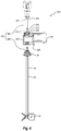
- mixing system 10A comprises a support housing 78, a cart 80A on which on which support housing 78 rests, a drive motor assembly 300, an adjustable arm assembly 302A which supports drive motor assembly 300 on support housing 78, a container assembly 16 that is supported within support housing 78, and drive shaft 362 ( Figure 3 ) that extends between drive motor assembly 300 and container assembly 16.
- container assembly 16 comprises a container 18 having a side 20 that extends from an upper end 22 to an opposing lower end 24. Upper end 22 terminates at an upper end wall 23 while lower end 24 terminates at a lower end wall 24.
- Container 18 also has an interior surface 26 that bounds a compartment 28. Compartment 28 is configured to hold a fluid.
- container 18 comprises a flexible bag that is comprised of a flexible, water impermeable material such as a low-density polyethylene or other polymeric sheets having a thickness in a range between about 0.1 mm to about 5 mm with about 0.2 mm to about 2 mm being more common. Other thicknesses can also be used.
- the material can be comprised of a single ply material or can comprise two or more layers which are either sealed together or separated to form a double wall container. Where the layers are sealed together, the material can comprise a laminated or extruded material.
- the laminated material comprises two or more separately formed layers that are subsequently secured together by an adhesive.
- the material is approved for direct contact with living cells and is capable of maintaining a solution sterile.
- the material can also be sterilizable such as by ionizing radiation. Examples of materials that can be used in different situations are disclosed in United States Patent No. 6,083,587 which issued on July 4, 2000, United States Patent Publication No. US 2003/0077466 A1, published April 24, 2003 , and United States Patent Publication No. US 2011/0310696 A1, published December 22,2011 .
- container 18 comprise a two-dimensional pillow style bag such as where two sheets of material are placed in overlapping relation and the two sheets are bonded together at their peripheries to form the internal compartment.
- container 18 can comprise a three-dimensional bag that not only has an annular side wall but also a two dimensional top end wall and a two dimensional bottom end wall. Further disclosure with regard to three-dimensional bags and method of manufacturing are disclosed in United States Patent Publication No. US 2002-0131654 A1, published September 19, 2002 and United States Patent Publication No. US 2011/0310696 A1, published December 22, 2011 .
- container 18 can be manufactured to have virtually any desired size, shape, and configuration.
- container 18 can be formed having a compartment sized to 10 liters, 30 liters, 100 liters, 250 liters, 500 liters, 750 liters, 1,000 liters, 1,500 liters, 3,000 liters, 5,000 liters, 10,000 liters or other desired volumes.
- the size of the compartment can also be in the range between any two of the above volumes.
- container 18 can be any shape, in one embodiment container 18 is specifically configured to be complementary or substantially complementary to the chamber of support housing 78 in which container 18 is received so that container 18 is properly supported therein when filled with fluid.
- container 18 has a flexible, bag-like configuration
- container 18 can comprise any form of collapsible container or semi-rigid container.
- the container can be accordioned or contain baffles that permit the container to expand and contract.
- portions of the container can be rigid while other portions are flexible.
- Container 18 can also be transparent or opaque and can have ultraviolet light inhibitors incorporated therein.
- a plurality of ports 30 at upper end 22 and a plurality of ports 31 at lower end 24 are formed on container 18.
- Each of ports 30, 31 communicate with compartment 28.
- container 18 can be formed with any desired number of ports 30,31 and that ports 30, 31 can be formed at any desired location on container 18 including along side 20 and on upper end wall 23 an lower end wall 25.
- Ports 30, 31 can be the same configuration or different configurations and can be used for a variety of different purposes.
- ports 30, 31 can be coupled with fluid lines for delivering media, cell cultures, gases and/or other components into container 18 and also withdrawing gases and fluids from container 18.
- Ports 30, 31 can also be used for coupling probes and/or sensors to container 18.
- ports 30, 31 can be used for coupling probes such as temperatures probes, pH probes, dissolved oxygen probes, dissolved CO 2 probes and the like.
- Various optical sensors and other types of sensors can also be attached to ports 30, 31. Examples of ports 30, 31and how various probes, sensors, and lines can be coupled thereto is disclosed in United States Patent Publication No. 2006-0270036, published November 30,2006 and United States Patent Publication No. 2006-0240546, published October 26, 2006 .
- Ports 30, 31 can also be used for coupling container 18 to secondary containers, to condenser systems, and to other desired fittings.
- container assembly 16 includes means for delivering a gas into the lower end of container 18.
- container assembly 16 can comprise a sparger 34 positioned either on or mounted to lower end 24 of container 18 for delivering a gas to the fluid within container 18.
- various gases are typically required in the growth of cells or microorganisms within container 18.
- the gas typically comprises air that is selectively combined with oxygen, carbon dioxide and/or nitrogen.
- other gases can also be used.
- the addition of these gases can be used to regulate the dissolved oxygen content and pH of a culture.
- a gas line 36 is coupled with sparger 34 for delivering the desired gas to sparger 34. Gas line 36 need not pass through lower end 24 of container 18but can extend down from upper end 22 or from other locations.
- Sparger 34 can have a variety of different configurations.
- sparger 34 can comprise a permeable membrane or a fritted structure comprised of metal, plastic or other materials that dispense the gas in small bubbles into container 18. Smaller bubbles can permit better absorption of the gas into the fluid.
- sparger 34 can simply comprise a tube, port, or other type opening formed on or coupled with container 18 through which gas is passed into container 18.
- the sparger can also be formed on or coupled with impeller 64, which is discussed below. Examples of spargers and how they can be used in the present invention are disclosed in United States Patent Publication Nos. 2006/0270036 and 2006/0240546 . Other conventional spargers can also be used.
- Container assembly 16 further comprises an impeller assembly 40.
- impeller assembly 40 comprises an elongated tubular connector 44 having a rotational assembly 48 mounted at one end and an impeller 64 mounted on the opposing end. More specifically, tubular connector 44 has a first end 46 and an opposing second end 48 with a passage 51 that extends therebetween.
- tubular connector 44 comprises a flexible tube such as a polymeric tube. In other embodiments, tubular connector 44 can comprise a rigid tube or other tubular structure.
- Rotational assembly 48 is mounted to first end 46 of tubular connector 44.
- Rotational assembly 48 comprises an outer casing 50 having an outwardly projecting flange 52 and a tubular hub 54 rotatably disposed within outer casing 50.
- a bearing assembly can be disposed between outer casing 50 and tubular hub 54 to permit free and easy rotation of hub 54 relative to casing 50.
- one or more seals can be formed between outer casing 50 and tubular hub 54 so that during use an aseptic seal can be maintained between outer casing 50 and tubular hub 54 as tubular hub 54 rotates relative to outer casing 50.
- Hub 54 has an interior surface 56 that bounds an opening 58 extending therethrough. As will be discussed below in greater detail, an engaging portion of interior surface 56 has a polygonal or other non-circular transverse cross section so that a driver portion of drive shaft 362 passing through opening 58 can engage the engaging portion and facilitate rotation of hub 54 by rotation of drive shaft 362.
- Hub 54 can also comprise a tubular stem 60 projecting away from outer casing 50. Hub 54 can couple with first end 46 of tubular connector 44 by stem 60 being received within first end 46. A pull tie, clamp, crimp or other fastener can then be used to further secure stem 60 to tubular connect 44 so that a liquid tight seal is formed therebetween. Other conventional connecting techniques can also be used.
- Impeller 64 comprises a central hub 66 having a plurality of fins 68 radially outwardly projecting therefrom. It is appreciated that a variety of different numbers and configurations of fins 68 can be mounted on hub 66.
- Hub 66 has a first end 70 with a blind socket 72 formed thereat.
- Socket 72 typically has a noncircular transverse cross section, such as polygonal, so that it can engage a driver portion of drive shaft 362. Accordingly, as will be discussed below in greater detail, when a driver portion is received within socket 72, the driver portion engages with impeller 64 such that rotation of drive shaft 362 facilities rotation of impeller 64.
- hub 66 and fins 68 of impeller 64 are molded from a polymeric material.
- hub 66 and fins 68 can be made of metal, composite, or a variety of other materials.
- an annular insert can be positioned within socket 72 to help reinforce hub 66.
- the insert can be comprised of metal or other material having a strength property greater than the material from which hub 66 is comprised.
- Impeller 64 can be attached to connector 44 by inserting first end 70 of hub 66 within connector 44 at second end 48. A pull tie, clamp, crimp, or other type of fastener can then be cinched around second end 48 of connector 44 so as to form a liquid tight sealed engagement between impeller 64 and connector 44.
- rotational assembly 48 is secured to container 18 so that tubular connector 44 and impeller 64 extend into or are disposed within compartment 28 of container 18.
- container 18 has an opening 74 at upper end 22.
- Flange 52 of outer casing 50 is sealed around the perimeter edge bounding opening 74 so that hub 54 is aligned with opening 74.
- Tubular connector 44 having impeller 64 mounted on the end thereof projects from hub 54 ( Figure 3 ) into compartment 28 of container 18.
- outer casing 50 is fixed to container 18 but hub 54, and thus also tubular connector 44 and impeller 64, can freely rotate relative to outer casing 50 and container 18.
- sealing opening 74 compartment 28 is sealed closed so that it can be used in processing sterile fluids.
- impeller assembly 40 is used in conjunction with drive shaft 362.
- drive shaft 362 comprises a head section 364 and a shaft section 366 that can be coupled together by threaded connection or other techniques.
- drive shaft 362 can be formed as a single piece member or from a plurality of attachable sections.
- Drive shaft 362 has a first end 368 and an opposing second end 370.
- Formed at first end 368 is a frustoconical engaging portion 372 that terminates at a circular plate 374.
- Notches 376 are formed on the perimeter edge of circular plate 374 and are used for engaging drive shaft 362 with a drive motor assembly as will be discussed below.
- driver portion 378 Formed at second end 370 of drive shaft 362 is a driver portion 378.
- Driver portion 378 has a non-circular transverse cross section so that it can facilitate locking engagement within hub 66 of impeller 64.
- driver portion 378 has a polygonal transverse cross section.
- a driver portion 380 is also formed along drive shaft 362 toward first end 368.
- Driver portion 380 also has a non-circular transverse cross section and is positioned so that it can facilitate locking engagement within the interior surface of hub 54 of rotational assembly 48.
- drive shaft 362 is advanced down through hub 54 of rotational assembly 48, through tubular connecter 44 and into hub 66 of impeller 64.
- rotation of drive shaft 362 by a drive motor assembly facilitates rotation of hub 54, tubular connecter 44 and impeller 64 relative to outer casing 50 of rotational assembly 48.
- impeller 64 fluid within container 18 is mixed.
- impeller assembly 40, drive shaft 362 and the discrete components thereof can have a variety of different configuration and can be made of a variety of different materials.
- Alternative embodiments of and further disclosure with respect to impeller assembly 40, drive shaft 362, and the components thereof are disclosed in US Patent Publication No. US 2011/0188928 A1, published August 4,2011 and US Patent Publication No. US 2011/0310696 A1, published December 22, 2011 .
- Container assembly 16A comprises container 18 having impeller assembly 40 attached thereto the same as in container assembly 16.
- container assembly 16A is primarily designed for mixing and transporting fluids.
- sparger 34 of container assembly 16 has been removed and replaced with a port 422 centrally secured on a floor 424 of container 18.
- a drain line 426 which is typically in the form of a flexible tube, is coupled to and extends from port 420.
- a hose clamp 427 can be attached to drain line 426 for controlling the flow of fluid therethrough.
- support housing 78 has a substantially cylindrical sidewall 82 that extends between an upper end 84 and an opposing lower end 86.
- Lower end 86 has a floor 88 mounted thereto.
- support housing 14 has an interior surface 90 that bounds a chamber 92.
- An annular lip 94 is formed at upper end 84 and bounds an opening 96 to chamber 92.
- chamber 92 is configured to receive container assembly 16 so that container 18is supported therein.
- support housing 78 is shown as having a substantially cylindrical configuration, in alternative embodiments support housing 78 can have any desired shape capable of at least partially bounding a compartment.
- sidewall 82 need not be cylindrical but can have a variety of other transverse, cross sectional configurations such as polygonal, elliptical, or irregular.
- support housing 78 can be scaled to any desired size.
- support housing 78 can be sized so that chamber 92 can hold a volume of less than 50 liters, more than 1,000 liters or any of the other volumes or range of volumes as discussed above with regard to container 18.
- Support housing 78 is typically made of metal, such as stainless steel, but can also be made of other materials capable of withstanding the applied loads of the present invention.
- floor 88 of support housing 78 can be formed with a central opening extending therethrough for gas line 36 ( Figure 2 ) to pass.
- any desired number of openings can be formed through sidewall 82 at lower end 86 to permit access to ports 31 ( Figure 2 ).
- One or more larger openings that are closed by a door can also be formed through sidewall 82 at lower end 86. The larger openings enable an operator to reach into chamber 92 for aligning container 18 and passing gas line 36( Figure 2 ) through the floor opening.
- means are provided for controlling the temperature of the fluid within container 18 when container 18 is disposed within support housing 78.
- support housing 78 is jacketed having a fluid inlet 184 and a fluid outlet 186. The jacket enables heated or cooled fluid to pass through support housing 78 for controlling the temperature of the fluid within container 18.
- electrical heating elements can be mounted on or within support housing 78.
- the temperature can be controlled by applying gas burners to support housing 78 or pumping the fluid out of container 18, heating the fluid and then pumping the fluid back into container 18.
- cart 80A comprises a platform 190 having atop surface 192 and an opposing bottom surface 194.
- platform 190 has a substantially square configuration. In alternative embodiments, however, platform 190 can be triangular, rectangular, circular, or of other polygonal or irregular configurations.
- Downwardly projecting from bottom surface 194 are a plurality of spaced apart wheels 196.
- a plurality of spaced apart legs 198 extend between floor 88 of support housing 78 and top surface 192 of platform 190. Legs 198 provide an open gap between support housing 78 and platform 190 so as to enable access to floor 88.
- cart 80A can be eliminated and support housing 78 can be supported by legs 198 on a ground or floor surface or on a pallet or other support structure.
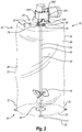
- drive motor assembly 300 is coupled with support housing 78 by adjustable arm assembly 302A.
- Drive motor assembly 300 is used in conjunction with drive shaft 362 ( Figure 3 ) and can be used for mixing and/or suspending a culture or other solution within container 18 ( Figure 2 ) .
- drive motor assembly 18 comprises a housing 304 having a top surface 306 and an opposing bottom surface 308.
- An opening 310 extends through housing 304 from top surface 306 to bottom surface 308.
- a tubular motor mount 312 is rotatably secured within opening 310 of housing 304. Upstanding from motor mount 312 is a locking pin 316.
- a drive motor 314 is mounted to housing 304 and engages with motor mount 312 so as to facilitate select rotation of motor mount 312 relative to housing 304.
- Drive shaft 362 is configured to pass through motor mount 312 so that engaging portion 372 of drive shaft 362 is retained within motor mount 312 and locking pin 316 of motor mount 312 is received within notch 376 of drive shaft 362.
- rotation of motor mount 312 by drive motor 314 facilitates rotation of drive shaft 362.
- arm assembly 302A is used to adjust the position of drive motor assembly 300 and thereby adjust the position of drive shaft 362 ( Figure 5 ) and impeller 64 ( Figure 2 ) mounted on the end thereof. As mentioned above and as will be discussed below in greater detail, the ability to adjust the position of impeller 64 enables optimal mixing of fluid within container 18.
- arm assembly 302A comprises a first housing 318A that is rigidly secured to upper end 84 of support housing 78. As shown in Figures 5 and 6 , slidably coupled with first housing 318A is an elongated first support 320A. A handle 410 is mounted to first support 320A for use in manually raising and lowering first support 320A.
- First housing 318A and first support 320A are orientated such that first support 320A can slide vertically up and down along a first axis 322A.
- first housing 318A and first support 320A can be disposed so that axis 322A is disposed at an angle in a range between 0° to about 30° relative to vertical. Other angles can also be used.
- means are provided for selectively locking first support 320A to first housing 318A at different locations along axis 322A.
- such means comprises holes 324A formed at spaced apart locations along first housing 318A and a spring activated pin 326A mounted to first support 320A.
- pin 326A By pulling out pin 326A, first support 320A is free to slide vertically up and down along axis 322A
- pin 326A By releasing or pushing in pin 326A, pin 326A is received within a corresponding hole 324A so as to lock first support 320A in place.
- first support 320A can be secured to first housing 318A.
- Indicia or markings can be formed along the surface of first support 320A and/or first housing 318A to indicate the relative position of first support 320A.
- a lift assist 412 is provided for assisting in raising and lowering first support 320A and drive motor assembly 300.
- lift assist 412 comprises a cylinder 414 having a first end pivotably coupled with the upper end of first support 320A and an opposing second end pivotably coupled with the lower end of first housing 318A or with support housing 78.
- Cylinder 412 is resiliently compressible.
- cylinder 412 can comprise two nested cylinders halves having a spring or compressible gas disposed therebetween.
- Cylinder 412 is positioned so that when first support 320A is lowered, cylinder 412 is resiliently compresses so that the produced resilient force can subsequently be used to assist the operator in raising first support 320A and drive motor assembly 300.
- Lift assist 412 thus permits an operator to easily and smoothly raise and lower first support 320A with drive motor assembly 300 mounted thereon.
- lift assist 412 can be automated to raise and lower first support 320A by activating a switch or through the use of a controller.
- lift assist 412 can be operated through the use of an electrical motor or through use of pneumatic or hydraulic systems.
- First support 320A terminates at an upper end 330A.
- Mounted on upper end 330A is a frame 416 having a side face 418.
- a second support 346A is rotatably mounted to side face 418 of frame 416.
- Second support 346A is mounted so that it rotates about a second axis 348A relative to frame 416.
- Second axis 348A can be disposed in a horizontal plane or at an angle in a range between about 0° to about 30° relative to the horizontal.
- Axis 348A can thus be perpendicular to axis 322A.
- Drive motor assembly 300 is secured to second support 346A such that rotation of second support 346A facilitates concurrent rotation of drive motor assembly 300.
- One embodiment of the present invention also includes means for locking second support 346A at different angles about second axis 348A.
- a spring activated pin 350A is mounted on an arm of second support 346A.
- second support 346A is free to rotate about second axis 348A.
- pin 350A is released or advanced inward, pin 350A is received within one of a plurality of holes formed on side face 418 of frame 416.
- second support 346A is thereby precluded from further rotation.
- Other conventional fastening techniques can also be used.
- second support 346A can be automated to rotate by activating a switch or through the use of a controller such as discussed above with regard to lift assist 412.
- first support 320A can facilitate vertical movement of drive motor assembly 300 while second support 346A can facilitate tilting of drive motor assembly 300. Because drive shaft 362 and impeller 64 move concurrently and proportionally with drive motor assembly 300, adjustable arm assembly 302A can thus be used to selectively position the vertical height and tilt of impeller 64.
- arm assembly 302A is used to properly position drive motor assembly 300 so that rotational assembly 48 ( Figure 2 ) can be coupled with drive motor assembly 300.
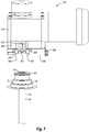
- housing 304 of drive motor assembly 300 has an open access 384 that is recessed on a front face 386 so as to communicate with opening 310 extending through housing 304.
- Access 384 is in part bounded by a substantially C- shaped first side wall 388 that extends up from bottom surface 308, a concentrically disposed substantially C-shaped second side wall 390 disposed above first side wall 388 and having a diameter larger than first side wall 388, and a substantially C-shaped shoulder 392 extending between side walls 388 and 390.
- a door 394 is hingedly mounted to housing 304 and selectively closes the opening to access 384 from front face 386.
- door 394 is secured in a closed position by a latch 396.
- first side wall 388 Positioned on first side wall 388 is a section 398 of a resilient and/or elastomeric material such as silicone. Other sections 398 of similar materials can also be positioned on first side wall 388 or the interior surface of door 394.
- rotational assembly 48 is horizontally slid into access 384 from front face 386 of housing 304 so that a support flange 400 radially outwardly extending from an upper end of rotational assembly 48 rests on shoulder 392 of access 384.
- Rotational assembly 48 is advanced into access 384 so that the passage extending through hub 54 of rotational assembly 48 aligns with the passage extending through motor mount 312 ( Figure 4 ). In this position, door 394 is moved to the closed position and secured in the closed position by latch 396.
- casing 50 of rotational assembly 48 is biased against the one or more sections 398 ( Figure 7 ) of resilient material so as to clamp rotational assembly 48 within access 384 and thereby prevent unwanted rotational movement of casing 50 relative to housing 304 of drive motor assembly 300.
- drive shaft 362 ( Figure 2 ) can be advanced down through drive motor assembly 300 and into impeller assembly 40 so as to engage impeller 64.
- drive motor assembly 300 is activated causing drive shaft 362 to rotate impeller 64 and thereby mix or suspend the fluid within container 18.
- drive shaft 362 is removed and rotational assembly 48 is separated from drive motor assembly 300.
- One advantage of being able to selectively adjust the vertical height and tilt of impeller 64 through the use of arm assembly 302A is that mixing assembly 10A can be used to maintain optimal mixing conditions of fluid within a single container assembly 16 over a relatively large change in fluid volumes.
- the preferred position for impeller 64 within container 18 to achieve optimal mixing can be determined using conventional techniques. This position can be measured as a height from the bottom of container assembly 16 and is subject to the height of the fluid within container assembly 16.
- the height of the location for impeller 64 to achieve optimal mixing also increases and vice-a-versa. Maintaining impeller 64 at the optimal location of mixing helps to ensure that the fluid is homogeneous.
- mixing system 10A is functioning as a bioreactor or fermentor.
- the media, additives, and cells or microorganism should be continually turned over and homogeneously dispersed to ensure that all of the cells and microorganism are being continuously and uniformly fed and oxygenated.
- the volume of fluid within container assembly 16 will vary significantly.
- the seed inoculum of cells or microorganisms can be dispersed into a rather small volume of media within container assembly 18.
- the seed inoculum can be delivered into a relatively large container assembly 16 although only a small volume of media is initially being used.
- impeller 64 is lowered to achieve optimal mixing of the initial volume.
- impeller 64 is progressively raised to maintain optimal mixing for the defined fluid volume.
- impeller 64 can again be progressively lowered as the fluid within container assembly 16is progressively lowered.
- a positive gas pressure within container assembly 16, such as in a range from 0.05 psi to about 2 psi to keep container assembly 16 away from the rotating impeller assembly 40 and to keep container 18 against heated support housing 78 to maintain temperature regulation. This can be more important during low volume processing.
- the ability to progressively add and remove relatively large amounts of fluid from a single container while maintaining optimal mixing of the fluid eliminates or at least decreases the need to transfer the solution to different sized containers for processing.
- the inventive system decreases processing down time, avoids the expense of unnecessary containers, minimizes the risk of contamination, and minimizes potential damage to cells/ microorganisms.
- the inventive system can operate over a relatively high tum-down ratio.
- a "tum-down ratio" is the ratio of maximum to minimum volumes of fluid that a single container can process while maintaining acceptable mixing conditions.
- a tum-down ratio of 10:1 means that if the initial volume that a mixing system can process at acceptable mixing conditions is 10 liters, the volume of fluid with the container can be increased by a factor of 10, i.e., up to 100 liters, and the system would still be able to process the fluid at acceptable mixing conditions.
- inventive mixing system 1OAas a bioreactor, fermentor, or other system that requires mixing or suspension it is appreciated that containers assembly 16 can be sized to operate with a tum-down ratio of at least 5:1, 10:1, 15:1, 20:1 or ranges therebetween.
- the mixing should, in general, assist in dispersal of the cells/ microorganisms and sparged gas throughout the solution so that the cells/ microorganisms has access to the required nutrients in the media and proper mass transfer is achieved with the sparged gas.
- the mixing should not be so sever as to apply unwanted shear forces to the cells/ microorganisms, create undesired splashing, or cause cavitation or a vortex in the solution, all of which can hamper the growth of cells/ microorganisms.
- adjustable arm assembly 302A can have a variety of different configurations.
- adjustable arm assembly 302A can be modified to permit select lateral displacement of drive shaft 362 and impeller 64 that is independent of tilting or vertical displacement.
- the adjustable arm assembly can be mounted on a separate docking station that removably couples with support housing 78.
- One specific example of such an adjustable arm assembly is disclosed in US Patent Publication No. US 2011/0310696 A1, published December 22, 2011 .
- One benefit of this design is that a single adjustable arm assembly can be used with multiple different support housings and particularly with support housings have different height and diameter sizes.
- impeller 64 may need to be adjusted laterally so that impeller 64 is centrally positioned to achieve optimal mixing. In other situations, lateral displacement may be desirable to permit mixing closer to or father away from the wall of container 18.
- drive motor assembly 300 operates with a container 404 that is an open top liner.
- Container 404 is positioned within chamber 92 of support housing 78 so that is drapes over annular lip 94 ( Figure 1 ).
- This configuration can be used as a lower cost alternative for mixing non-sterile fluids.
- rotational assembly 48 merely functions to secure impeller assembly 40 to drive motor assembly 300 so that it does not unintentionally slide off of drive shaft 362.
- rotational assembly 48 can be substantially simplified.
- rotational assembly 48 can be replaced by a clamp 406 that secures tubular connector 44 to drive shaft 362.
- impeller assembly 40 and how they can be attached to drive motor assembly 300 or drive shaft 362 are discussed in US Patent Publication No. US 2011/0188928 A1, published August 4, 2011 .
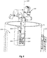
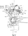
- mixing system 10B comprises support housing 78, cart 80A on which on which support housing 78 rests, drive motor assembly 300, an adjustable arm assembly 302B which supports drive motor assembly 300, container assembly 16 that is supported within support housing 78, and drive shaft 362 ( Figure 12 ) that extends between drive motor assembly 300 and impeller assembly 40 of container assembly 16.
- the primary difference between mixing systems 10A and 10B is the modification of adjustable arm assembly 302B relative to adjustable arm assembly 302A.
- adjustable arm assembly 302B is in the form of a programmable robotic arm having multiple axes of rotation that enable the robotic arm to periodically or continuously adjust the position of impeller 64 three dimensionally, including tilting of impeller 64.
- adjustable arm assembly 302B includes a lower base 430 that is mounted on a support platform 432 projecting from supporting housing 78.
- An upper base 434 is mounted on lower base 430 by a first swivel joint 436.
- First swivel joint 436 permits upper base 434 to rotate relative to lower base 432 about a first axis 438 that is vertically oriented or can be offset from vertical over an angel in a range from about 0° to about 30°.
- a first motor 440A is mounted on upper base 434 and engages with first swivel joint 436 for controlling rotation of upper base 434 about first axis 438.
- first arm 442 having a first end 444 and an opposing second end 446.
- First end 444 is rotatably mounted to upper base 434 by a second swivel joint 448.
- Second swivel joint 448 rotates about a second axis 450 that is horizontally disposed and/or extends perpendicular to first axis 438.
- a second motor 440B engages with second swivel joint 448 for controlling rotation of first end 444 of first arm 442 about second axis 450.
- Arm assembly 302B also includes a second arm 452 having a first end 454 and an opposing second end 456.
- First end 454 of second arm 452 is rotatably mounted to second end 446 of first arm 442 by way of a third swivel joint 458.
- Third swivel joint 458 rotates about a third axis 460 that is also horizontally disposed and/or is parallel to second axis 450.
- a motor 440C engages third swivel joint 458 for controlling rotation of first end 454 of second arm 452 about third axis 460.
- Drive motor assembly 300 is rotatably coupled to second end 456 of second arm 452.
- a flange 462 projects out from a side of housing 304 of drive motor assembly 300.
- Second end 456 of second arm 452 is rotatably mounted to mount 464 by a fourth swivel joint 466.
- Fourth swivel joint 466 rotates about a fourth axis 468 which is also horizontally disposed and/or is parallel to axis 450 and 460.
- a motor 440D is shown mounted at first end 454 of second arm 452 and is operably coupled with fourth swivel joint 466 for controlling rotation of drive motor assembly 300 about fourth axis 468. In alternative embodiments, it is appreciated that motor 440 can be secured to mount 464.
- a fifth swivel joint 470 can be formed on second arm 452 at a location between opposing ends 454 and 456. Swivel joint 470 rotates about a fifth axis 472 that centrally extends along the length of second arm 452 and extends orthogonal to axis 460 and 468.
- Motor 440E is disposed at first end 454 of second arm 452 and is operably coupled with fifth swivel joint 470 so as to enable drive motor assembly 300 to rotate about fifth axis 472.
- second arm 452 can also be a telescoping arm that can selectively lengthen and retract.
- a motor 440F couples with second arm 452 to control the telescoping expansion and contraction of second arm452.
- adjustable arm assembly 302B can be manipulated to position impeller 64 over a wide range of positions and orientations within container assembly 16 to facilitate optimum mixing therein. Furthermore, adjustable arm assembly 302B can be programmed to periodically or continuously adjust the position of impeller 64 to optimize mixing within container assembly 16. For example, each of motors 440A-440F of adjustably arm assembly 302B and drive motor 314 of drive motor assembly 300 can be electrically connected to electrical coupler 474.
- electrical coupler 474 can be selectively coupled to a controller 475 having a central processing unit that can be programmed to simultaneously control operation of all the motors and thereby control not only the speed of rotation of impeller 64 but also its desired position.
- controller 475 having a central processing unit that can be programmed to simultaneously control operation of all the motors and thereby control not only the speed of rotation of impeller 64 but also its desired position.
- adjustable arm assembly 302B can be used to move impeller 64 along a continuous 2-dimensional path or 3-dimensional path.
- each of motors 440A-F comprises an electrical motor which communicates with the corresponding swivel joints through a direct drive, gear drive, pulley system, or the like.
- one or more motors can drive the swivel joints through pneumatics, hydraulics or other conventional systems.
- the motors need not be mounted directly to arm assembly 302B but can be located remotely with fluid lines coupled to the assembly for controlling movement.
- mixing system 10B can operate over a higher tum-down ratio than prior embodiments.
- mixing system 10B can be used to produce tum-down ratios in the range of at least east 50:1 or 80:1 and more commonly at least 20:1, 30:1, or 40:1. Other ratios can also be achieved.
- container assembly 16 During use of mixing systems 10A and 10B rotational assembly 48 ( Figure 2 ) of container assembly 16 is directly coupled within drive motor assembly 300.
- the flexible nature of container 18 enables adjustable arm assemblies 302A and 302B to freely tilt and to move vertically and horizontally each of drive motor assembly 300, rotational assembly 48, drive shaft 362 and impeller 64 during the rotation of impeller 64.
- container 18 may need to be oversized relative to support housing 78 when used with adjustable arm assemblies 302A and 302B so that when container 18 is filled to its maximum level with fluid, there is still a sufficient amount of flexible container 18 extending above the fluid level to permit free movement of the assembled drive motor assembly 300, rotational assembly 48, drive shaft 362 and impeller 64.
- Controller 475 can be electronically coupled with a variety of components of both mixing systems 10A and 10B that control operational parameters.
- controller 475 can be electrically coupled with drive motor assembly 300, arm assembly 302B, gas regulator 500, fluid temperature regulator 502, fluid sensors 504 and volume sensors 506.
- Gas regulator 500 controls that flow rate and mixture of gasses that are delivered to sparger 34 through gas line 36 ( Figure 2 ) .
- the gases typically include air that is selectively combined with oxygen, carbon dioxide and/or nitrogen but other gases can also be used.
- Fluid temperature regulator 502 controls operation of the boiler that is used to heat and pump the fluid through jacketed support housing 78 for regulating the temperature of the fluid within container 18.
- Fluid sensors 504 are coupled with container 18 or otherwise interact with the fluid therein for detecting properties of the fluid.
- Examples of fluid sensors 504 include temperature probes, pH probes, dissolved O 2 probes, dissolved CO 2 probes, optical density sensors that sense the density of the fluid, conductivity sensors, and viscosity sensors.
- Volume sensors 506 can come in a variety of different configurations and are used to detect the volume or level of fluid within container 18.
- volume sensors 506 comprise load cells 476 positioned between support housing 78 and cart 80A. Load cells 476 provide signals to controller 475 that reflect the weight or change in weight of support housing 78 due to the addition or subtraction of fluid in container 18. In tum, controller 475 uses this information in an algorithm to calculate the volume or level of fluid within container 18.
- means are provided for sensing the volume or level of fluid within container 18. One example of such means includes load cells 476 as discussed above.
- load cells 476 can be replaced with optical sensors or pressure sensors located along the side of support housing 78 or container 18and which sense the height of the fluid.
- floats or other mechanical sensors can be used to measure the rising or lower of the fluid within container 18.
- Other conventional techniques can also be used.
- mixing systems 10A and 10B can be used as a bioreactor or fermentor for growing cells or microorganisms.
- a first solution having a first volume is dispensed into compartment 28 of container 18 and comprises media, cells or microorganisms, and other components as desired.
- the solution can be a small volume that contains an initial seed inoculum or a larger volume of a partially processed culture that is being moved to a larger container for further growth.
- impeller 64 is moved to the desired location within compartment 28 to facilitate desired mixing for the first volume of fluid. Impeller 64 is activated and set to run at a defined speed causing mixing of the solution while gas is delivered to sparger 34 to oxygenate and regulate other mass transfer with the solution.
- fluid temperature regulator 502 is set to heat the fluid within container 18 to a desired level. Under these conditions, the cells/microorganisms are left to propagate within the solution.
- additional media can be added either at a continuous flow rate or as a batch at staggered intervals. In either event, the media is added so that the density of the cells/microorganisms does not exceed a predetermined maximum density for optimal growth and does not drop below a predetermined minimum density for optimal growth.
- the density values are generally more important for the growth of cells than microorganisms.
- This adjustment of impeller 64 can be through manual manipulation of arm assembly 302B, manually inputting commands into controller 475 for repositioning arm assembly 302B, or preprogrammed automatic adjustment of arm assembly 302B by controller 475 based on inputs from volume sensor 506.
- the interval between adjustments many be longer and the moved displacement of impeller 64 greater.
- the addition of solution and the vertical movement of impeller is at a slower rate for small volumes of fluid and increases as the size of the culture increases.
- the displacement of impeller may be at least 5 cm, 10 cm, 20 cm, or more.
- the movement of impeller 64 can be at much shorter intervals and at much smaller increments and in some situations, such as for large volumes of fluid, the movement of impeller 64 can be continuous.
- impeller 64 will be moved to the second elevated position during continuous operation of impeller 64. In some situations, however, impeller 64 can be stopped, moved to the second position, and then restarted. Once impeller 64 is moved to the second position, the process is repeated. That is, the density of the cells/microorganisms is monitored, additional media is added to the culture to regulate density, and impeller 64 is moved, either continuously or in one or more steps, to a third position to continue to maintain desired mixing conditions. In contrast to adding media based on cells/microorganism density, the media can be added at a fixed rate, at set intervals, or based on other measured processing parameters.
- impeller 64 can also be incrementally or continuously lowered within container 18 as solution is drawn out of container 18.
- the speed, tilt, and/or lateral position of impeller 64 can also be adjusted.
- the rotational speed of impeller 64 can be adjusted to account for the increase or decrease in fluid volume. This adjustment can be manual or automatic through controller 475 based on the sensed change in volume or fluid height. For example, when the fluid volume within container 18 gets relatively small, the speed of impeller 64 necessary to maintain proper mixing can be reduced. Failure to reduce impeller speed in low fluid volumes can result in unwanted gas entrapment and splashing of the solution. Likewise, as the fluid volume increases, it may be necessary to increase the impeller speed in addition to moving the impeller to achieve a desired mixing.
- Tilting impeller 64 can adjust the circulation flow. For example, increasing lateral tilt decreases radial flow in favor of a more random flow. Tilting impeller 64 by a few degrees may thus be sufficient to maintain desired mixing at some increased fluid volumes. Periodic or continuous tilting of impeller 64 back and forth over a range of angles can also be used as one mechanism for maintaining desired mixing conditions.
- Lateral displacement of impeller 64 within container 18 also influences the flow pattern of the fluid within container 18 and thus the mixing thereof.
- optimal fluid mixing may be achieved by locating impeller 64 at different lateral positions within container 18 as the level of the fluid within container 18 changes.
- periodic or continuous changing of the lateral position of impeller 64 can periodically or continuously change the flow pattern of the fluid and thus be used to achieve desired mixing conditions.
- controller 475 can be programmed to operate arm assembly 302B so that impeller 64 is periodically or continuously moved along a fixed or random horizontal 2-dimensional path within container 18. This may be particularly helpful where the fluid volume in container 18 is so large that keeping impeller 64 at a fixed location will not be sufficient to maintain desired mixing of the entire fluid volume.
- controller 475 can be programmed to operate arm assembly 302B so that rotational speed, tilt, lateral displacement and/or vertical displacement of impeller 64 can be periodically or continuously adjusted to achieve desired mixing conditions as the volume of fluid mcreases.
- controller 475 can be programmed to operate arm assembly 302B so that rotational speed, tilt, lateral displacement and/or vertical displacement of impeller 64 can be periodically or continuously adjusted to achieve desired mixing conditions as the volume of fluid mcreases.
- controller 475 can be programmed to operate arm assembly 302B so that rotational speed, tilt, lateral displacement and/or vertical displacement of impeller 64 can be periodically or continuously adjusted to achieve desired mixing conditions as the volume of fluid mcreases.
- controller 475 can be programmed to continuously or periodically adjust the position and/or orientation of impeller 64.
- impeller 64 can be adjusted horizontally, vertically and/or tilted in different orientations. By changing the position and/or orientation of impeller 64 the force on the fluid is changed which disrupts or prevents the formation of a vortex and produces a more turbulent flow.
- controller 475 can be programmed to operate arm assembly 302B so that impeller 64 is periodically or continuously moved along a fixed or random 3- dimensional path within container 18.In addition to moving along the 3-dimensional path, the speed and tilt of impeller 64 can also be adjusted.
- drive shaft 362 and associated impeller 64 can be moved in a pattern opposite to the direction in which impeller 64 rotates.
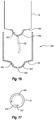
- Figure 17 shows a cross sectional top plan schematic view of container assembly 18 having drive shaft 362 disposed therein.
- Drive shaft 362, and thus impeller 64 can be rotated by drive motor assembly 300 in a clockwise direction as identified by arrow 478.
- adjustable arm assembly 302B can be moving drive shaft 362 and impeller 64 within container assembly 16 in a counterclockwise path along arrow 480. This movement in opposite directions can help eliminate the formation of a vortex.
- This automatic adjusting of the impeller location and speed can have a significant influence during critical applications.
- aluminum or other solutes, adjuvants and/or suspensions are commonly added to boost or stabilize the dose potency.
- the dense materials can settle out very easily and the solution must remain well mixed until the final few liters are drained.
- adjustable arm assembly 302B can continuously or periodically move impeller 64 in a horizontal pattern within container 18, such as along the circular path of arrow 480 in Figure 16 . This horizontal movement of impeller 64 enables impeller 64 to have lower tip speed or rotational speed which minimizes cell damage but still maintain a generally uniform mixing of the fluid.
- impeller 64 can be moved in a variety of different patterns such as a triangle or other polygonal patterns or in a repeating wave pattern. Varying the tilt of impeller 64, either in conjunction with or independent of the horizontal movement of impeller 64, can also help achieve uniform mixing at low impeller speed.
- controller 475 can be operated by a automated program that uses computational fluid dynamic modeling in conjunction with sensed critical process variables to provide real time feedback for dynamically controlling the position, speed, orientation, and/or movement pattern of impeller 64. For example, based on input from fluid sensors 504 and volume sensors 506, controller 475 can monitor the process variables of volume, gassing rate, pH, dissolved O 2 , dissolved CO 2 , conductivity, density, viscosity, and/or flow pattern of the solution. When any of the process variables fall outside of a predefined range, controller 475 automatically makes adjustments to gas regulator 500, fluid temperature regulator 502, arm assembly 302B and/or drive motor assembly 300 to correct the process variable.
- controller 475 can dynamically regulate the position, speed, orientation, and/or movement pattern of impeller 64 through arm assembly 302B and drive motor assembly 300 to correct the processing variable. For example, if the cell or microorganism density is found to be too high at a certain location within container 18, as could be determined by multiple optical density sensors couple about container 18, impeller 64 may be automatically moved to a defined location within container 18 to improve the overall mixing of the fluid or may be temporarily moved closer to the location where the cells/microorganism have the highest density so that those cells/microorganism are properly mixed.
- controller 475 can automatically set impeller 64 to move to certain locations or to travel along a certain 2- or 3-dimensional path. It is appreciated that the possible alternatives as to when and how the position, speed, orientation, and/or movement pattern of impeller 64 can be adjusted are extensive. The programmed system, however, continuous to make dynamic adjustments to the system based on real time sensed processing parameters until processing of the fluid is completed.
- floor 88 or the lower end of support housing 78 can be made having a steep conical configuration into which container 18 having a complementary configuration can be received and impeller 64 can be lowered.
- FIG 15 depicted in Figure 15 is a cross sectional side view of one embodiment of support housing 78 in which floor 88 has a conical configuration with an interior surface 482 sloping at an angle a relative to the horizontal.
- the angel a can be in a range between about 35 ° to about 70° with about 45 ° to about 70° and about 55 ° to about 70° being more common. Other angles can also be used.
- Impeller 64 By inwardly tapering the floor or lower end of support housing 78, smaller volumes of solution can be formed within container 18that retain a sufficient depth and width to enable impeller 64 to be lowered therein. Impeller 64 can thus be submerged and rotated within the smaller volumes to maintain proper mixing.
- a support housing 78A is formed having a sidewall that extends down to floor 88.
- a receiver 482 Centrally formed on floor 88 is a receiver 482 that bounds a recess 484.
- receiver 482 and recess 484 have a semi- spherical configuration. In other embodiments, receiver 482 and recess 484 can have other shapes.
- Floor 88 is annular and slopes toward receiver 482.
- a port 486 is centrally formed through the bottom of receiver 482.
- Container 18 is shown having floor 424. Centrally secured to floor 424, such as by welding, is a dish 488 which bounds a cavity 490. Fluid line 426 couples with the bottom of dish 488 so as to communicate with cavity 490. During assembly, dish 488 is received and supported within receiver 482 so that fluid line 426 passes out through port 486. Receiver 482 typically has a configuration complementary to dish 488. Dish 488 can be comprised of a rigid or semi-rigid material such as a plastic or composite. Alternatively, dish 488 can be formed from a polymeric sheet or film, such as that used to form container 18.
- dish 488 has a width and depth that enables impeller 64 to be lowered therein. Impeller 64 can thus be submerged and rotated within cavity 490 to maintain proper mixing of the relatively small volume of fluid container therein.
- Dish 488 is typically configured so that cavity 490 has a semi- spherical configuration or an elongated semi-spherical configuration. However, cavity 490 can also be formed into other configurations that will receive impeller 64. Cavity 490 can have a volume in a range between about 5 liters to about 40 liters with about 5 liters to about 20 liters or 5 liter to about 10liters being more common.
- adjustable arm assembly 302B can be used in association with container 404, depicted in Figure 9 , which is an open top liner.
- rotational assembly 48 can be used to secure impeller assembly 40 to drive motor assembly 300 or, as shown in Figure 10 , rotational assembly 48 can be replaced by a clamp 406 that secures tubular connector 44 to drive shaft 362.
- impeller assembly 40 ( Figure 3 ) can be eliminated.
- container 18 has a drive shaft 362A that projects directly into compartment 28.
- Drive shaft 362A can have substantially the same configuration as drive shaft 362 except that an impeller 64A is rigidly fixed directly to the end thereof within compartment 28.
- a dynamic seal 492 is used to form an aseptic seal between container 18 and shaft section 366 of drive shaft 362A. Seal 492 also enables drive shaft 362A to rotate relative to container 18 while maintaining the aseptic seal.
- Drive shaft 362A includes head section 364 which threads or otherwise secures to shaft section 366 as shown in Figure 3 .
- Head section 364 can thus be attached to drive motor assembly 300 ( Figure 11 ) prior to securing head section 364 to shaft section 366.
- drive shaft 362A can be formed as a single integral member and a different structure can be used to secure drive shaft 362A to drive motor assembly 300.
- Shaft section 366 or the entire drive shaft 362A can be made from a plastic or composite material that is disposed of after use.
- shaft section 366 or the entire drive shaft 362A can be made of a metal that is sterilized and reused.
- Adjustable arm assembly 302B is only one example of a programmable robotic arm that can be used with the present invention. It is appreciated any number of conventional robotic arms can be used in the present invention. Furthermore, it is appreciated that other robotic arms need not have all of the degrees of freedom incorporated into adjustable arm assembly 302B. For example, the robotic arm may only be able to move impeller 64 vertically up and down but not move laterally or tilt. Other robotic arms may have any combination of being able to move impeller 64 vertically, laterally, and/or tilt. Thus, the robotic arms can be designed to move impeller 64 in one dimension, two dimensions, or three dimensions. It is likewise appreciate that adjustable arm assembly 302B need not be in the shape of a conventional robotic arm. For example, adjustable arm assemblies 302A can be modified to incorporate motors for moving the various supports and those motors can be electronically coupled to controller 475 for automatically controlling the movement of impeller 64.
- impeller 64 as the sole mixing element. In other embodiments, however, it is appreciated that impeller 64 can be replaced with other mixing elements.
- a magnetically driven impeller could be rotatably mounted on the end of dive shaft 362.
- drive shaft 362 could still be used to elevate, tilt, or move the impeller in a pattern
- a magnetic drive source located outside of container 19 could be used to rotate the impeller.
- drive motor assembly 300 could be eliminated.
- the ends of a fluid inlet tube and a fluid outlet tube could be mounted on the end of draft shaft 362. Fluid could be drawn out of container 18 through the outlet tube while the fluid is pumped back into container 18 through the inlet tube.
- the fluid being drawn out of and pumped into container 18 can mix the remaining fluid within container 18.
- drive shaft 362 can be used to elevate, tilt, or move the ends of the tubes.
- the end of a gas line can be mounted to the end of drive shaft 362. The gas blown out of the gas line can be used to mix the fluid.
- impeller 64 can be replaced with a paddle, baffle, or other structure that can be swiveled, rotated, reciprocated, pivoted or otherwise moved within container 18for mixing the fluid therein.
- inventive fluid mixing systems achieve a number of benefits.
- the inventive systems permit fluids, and particularly cell and microorganism cultures, to be processed within a single container over a significantly larger tum down ratio than prior systems.
- the fluid mixing systems enable fluids to be mixed within a single container at a desired turnover or mixing rate over a broad range of fluid volumes.
- the inventive mixing systems provide improved mixing capabilities and improved fluid processing capabilities.
Description
- The present invention relates to methods and systems for mixing fluids, namely, biological fluids.
- The biopharmaceutical industry uses a broad range of mixing systems for a variety of processes such as in the preparation of media and buffers and in the growing of cells and microorganisms in bioreactors. Some conventional mixing systems, including bioreactors, comprise a flexible bag disposed within a rigid support housing. An impeller is disposed within the flexible bag and is used to mix or suspend the solution within the bag. In some embodiments, the impeller is mounted to the bottom of the bag and is magnetically driven. In other embodiments, the impeller is fixed on the end of a drive shaft that projects into the flexible bag. In both embodiments, however, the impeller is designed to remain at a substantially fixed position which is optimal for mixing a narrowly defined volume of solution in the flexible bag. To enable homogeneous mixing of larger volumes of solution, larger bags are used that have an impeller positioned at a location that is optimal for that size of bag.
JP2011092117
US2008/186802 discloses a system for mixing bioprocessing fluid that includes vertically aligned mixing arms within a container. The height of the arm is adjustable. - In some processing procedures it can be desirable to initially mix solutions at a low volume and then progressively increase the volume of the solution. For example, this is a common procedure used with bioreactors for growing cells. The process typically entails dispensing a seed inoculum in a growth media contained within a relatively small bag and then transferring the solution to progressively larger bags where additional media is added as the cells grow and multiple. This process is repeated until a final desired volume is achieved. By transferring the solution to different sized bags which each have a corresponding mixer, the operator can ensure homogeneous mixing of each of the different volumes.
- Although the above process of moving solutions to different sized bags to maintain proper mixing and suspension is functional, the procedure has some shortcomings. For example, the necessity of stepping to different sized bags is labor
intensive, time consuming, and has high material costs in that the multiple bags are discarded after use. Furthermore, transferring between different bags produces some mixing down- time which can influence cell growth. In addition, the necessity of shifting between bags increases the risk of contamination to the solution and potential damage to the cells. - Accordingly, what is needed in the art are improved mixing systems that solve all or some of the above problems. BRIEF DESCRIPTION OF THE DRAWINGS
- Various embodiments of the present invention will now be discussed with reference to the appended drawings. It is appreciated that these drawings depict only typical embodiments of the invention and are therefore not to be considered limiting of its scope.
-
Figure 1 is a perspective view of a fluid mixing system; -
Figure 2 is a perspective view of the container assembly of the fluid mixing system shown inFigure 1 ; -
Figure 2A is a perspective view of an alternative container assembly; -
Figure 3 is an elevated side view of an impeller assembly of the container assembly shown inFigure 2 and a drive shaft; -
Figure 4 is a partially disassembly perspective view of a drive motor assembly of the fluid mixing system shown inFigure 1 in association with the impeller assembly and drive shaft ofFigure 3 ; -
Figure 5 is a right side perspective view of the adjustable arm assembly of the mixing system shown inFigure 1 ; -
Figure 6 is a left side perspective view of the adjustable arm assembly shown inFigure 5 ; -
Figure 7 is a front perspective view of the drive motor assembly and rotational assembly; -
Figure 8 is an elevated front view of the rotational assembly shown inFigure 7 coupled with the drive motor assembly; -
Figure 9 is a perspective view of an alternative embodiment of a container being used with a drive motor assembly and impeller assembly; -
Figure 10 is a perspective view of an alternative embodiment of the impeller assembly shown inFigure 9 ; -
Figure 11 is a perspective view of another alternative embodiment of a mixing system incorporating features of the present invention; -
Figure 12 is a right side perspective view of the adjustable arm assembly of the mixing system shown inFigure 11 ; -
Figure 13 is a left side perspective view of the adjustable arm assembly shown inFigure 12 ; -
Figure 14 is a block diagram showing the controller of the mixing system shown inFigure 12 electrically coupled to other components of the mixingsystem; -
Figure 15 is a cross sectional side view of one embodiment of the support housing shown inFigure 11 ; -
Figure 16 is a cross sectional side view of an alternative embodiment a flexible container having a dish mounted to the floor thereof and a support housing configured to receive the container; -
Figure 17 is a schematic top plan view of the support housing shown inFigure 11 showing rotation and movement of the drive shaft; and -
Figure 18 is a cross sectional side view of an alternative embodiment of a drive shaft coupled to a flexible container by a dynamic seal. - As used in the specification and appended claims, directional terms, such as "top," "bottom," "left," "right," "up," "down," "upper," "lower," "proximal," "distal" and the like are used herein solely to indicate relative directions and are not otherwise intended to limit the scope of the invention or claims.
- The present invention relates to systems and methods for mixing and, if desired, sparging solutions and/or suspensions. The systems can be commonly used as bioreactors or fermentors for culturing cells or microorganisms. By way of example and not by limitation, the inventive systems can be used in culturing bacteria, fungi, algae, plant cells, animal cells, protozoan, nematodes, and the like. The systems can accommodate cells and microorganisms that are aerobic or anaerobic and are adherent or non-adherent. The systems can also be used in association with the formation and/or treatment of solutions and/or suspensions that are for biological purposes, such as media, buffers, or reagents. The systems can also be used for mixing powders or other components into a liquid where sparging is not required and/or where is solution is not for biological purposes.
- Some embodiments of the inventive systems are designed so that a majority of the system components that contact the material being processed can be disposed of after each use. As a result, the inventive systems substantially eliminate the burden of cleaning and sterilization required by conventional stainless steel mixing systems. This feature also ensures that sterility can be consistently maintained during repeated processing of multiple batches. The inventive systems are also adjustable so that they can be used for mixing a variety of different batch sizes. In view of the foregoing, and the fact that the inventive systems are easily scalable, relatively low cost, and easily operated, the inventive systems can be used in a variety of industrial and research facilities that previously outsourced such processing.
- Some embodiments of the present invention also enable manual or automatic adjustment of the position, tilt, and/or movement pattern of the mixing element within the solution. This ability to adjust the position, tilt, and/or movement pattern of the mixing element enables optimal mixing or suspension of the solution as the volume, properties or critical processing parameters of the solution varies.
- Depicted in
Figure 1 is one embodiment of aninventive mixing system 10A incorporating features of the present invention. In general,mixing system 10A comprises asupport housing 78, acart 80A on which on which supporthousing 78 rests, adrive motor assembly 300, anadjustable arm assembly 302A which supportsdrive motor assembly 300 onsupport housing 78, acontainer assembly 16 that is supported withinsupport housing 78, and drive shaft 362 (Figure 3 ) that extends betweendrive motor assembly 300 andcontainer assembly 16. The various components of mixingsystem 10A will now be discussed in greater detail. - As depicted in
Figure 2 , container assembly 16comprises acontainer 18 having a side 20 that extends from anupper end 22 to an opposinglower end 24.Upper end 22 terminates at anupper end wall 23 whilelower end 24 terminates at alower end wall 24.Container 18 also has aninterior surface 26 that bounds acompartment 28.Compartment 28 is configured to hold a fluid. In the embodiment depicted,container 18 comprises a flexible bag that is comprised of a flexible, water impermeable material such as a low-density polyethylene or other polymeric sheets having a thickness in a range between about 0.1 mm to about 5 mm with about 0.2 mm to about 2 mm being more common. Other thicknesses can also be used. The material can be comprised of a single ply material or can comprise two or more layers which are either sealed together or separated to form a double wall container. Where the layers are sealed together, the material can comprise a laminated or extruded material. The laminated material comprises two or more separately formed layers that are subsequently secured together by an adhesive. - The material is approved for direct contact with living cells and is capable of maintaining a solution sterile. In such an embodiment, the material can also be sterilizable such as by ionizing radiation. Examples of materials that can be used in different situations are disclosed in United States Patent No.
6,083,587 which issued on July 4, 2000, United States Patent Publication No.US 2003/0077466 A1, published April 24, 2003 , and United States Patent Publication No.US 2011/0310696 A1, published December 22,2011 . - In one embodiment,
container 18 comprise a two-dimensional pillow style bag such as where two sheets of material are placed in overlapping relation and the two sheets are bonded together at their peripheries to form the internal compartment. In other embodiments, as depicted inFigure 2 container 18 can comprise a three-dimensional bag that not only has an annular side wall but also a two dimensional top end wall and a two dimensional bottom end wall. Further disclosure with regard to three-dimensional bags and method of manufacturing are disclosed in United States Patent Publication No.US 2002-0131654 A1, published September 19, 2002 and United States Patent Publication No.US 2011/0310696 A1, published December 22, 2011 . - It is appreciated that
container 18 can be manufactured to have virtually any desired size, shape, and configuration. For example,container 18 can be formed having a compartment sized to 10 liters, 30 liters, 100 liters, 250 liters, 500 liters, 750 liters, 1,000 liters, 1,500 liters, 3,000 liters, 5,000 liters, 10,000 liters or other desired volumes. The size of the compartment can also be in the range between any two of the above volumes. Althoughcontainer 18 can be any shape, in oneembodiment container 18 is specifically configured to be complementary or substantially complementary to the chamber ofsupport housing 78 in whichcontainer 18 is received so thatcontainer 18 is properly supported therein when filled with fluid. - Although in the above discussed
embodiment container 18 has a flexible, bag-like configuration, in alternative embodiments it is appreciated thatcontainer 18 can comprise any form of collapsible container or semi-rigid container. For example, the container can be accordioned or contain baffles that permit the container to expand and contract. In other embodiments, portions of the container can be rigid while other portions are flexible.Container 18 can also be transparent or opaque and can have ultraviolet light inhibitors incorporated therein. - Continuing with
Figure 2 , formed oncontainer 18 are a plurality ofports 30 atupper end 22 and a plurality ofports 31 atlower end 24. Each ofports 30, 31communicate withcompartment 28. Although only afew ports ports ports container 18 including along side 20 and onupper end wall 23 anlower end wall 25.Ports ports container 18 and also withdrawing gases and fluids fromcontainer 18. -
Ports container 18. For example, whencontainer 18 is used as a bioreactor for growing cells or microorganisms,ports ports ports 30, 31and how various probes, sensors, and lines can be coupled thereto is disclosed in United States Patent Publication No.2006-0270036, published November 30,2006 and United States Patent Publication No.2006-0240546, published October 26, 2006 .Ports coupling container 18 to secondary containers, to condenser systems, and to other desired fittings. - In one embodiment of the present invention,
container assembly 16 includes means for delivering a gas into the lower end ofcontainer 18. By way of example and not by limitation,container assembly 16 can comprise asparger 34 positioned either on or mounted tolower end 24 ofcontainer 18 for delivering a gas to the fluid within container
18. As is understood by those skilled in the art, various gases are typically required in the growth of cells or microorganisms withincontainer 18. The gas typically comprises air that is selectively combined with oxygen, carbon dioxide and/or nitrogen. However, other gases can also be used. The addition of these gases can be used to regulate the dissolved oxygen content and pH of a culture. Agas line 36 is coupled withsparger 34 for delivering the desired gas tosparger 34.Gas line 36 need not pass throughlower end 24 of container 18but can extend down fromupper end 22 or from other locations. -
Sparger 34 can have a variety of different configurations. For example,sparger 34 can comprise a permeable membrane or a fritted structure comprised of metal, plastic or other materials that dispense the gas in small bubbles intocontainer 18. Smaller bubbles can permit better absorption of the gas into the fluid. In other embodiments,sparger 34 can simply comprise a tube, port, or other type opening formed on or coupled withcontainer 18 through which gas is passed intocontainer 18. In contrast to being disposed oncontainer 18, the sparger can also be formed on or coupled withimpeller 64, which is discussed below. Examples of spargers and how they can be used in the present invention are disclosed in United States Patent Publication Nos.2006/0270036 and2006/0240546 . Other conventional spargers can also be used. -
Container assembly 16 further comprises animpeller assembly 40. As depicted inFigure 3 ,impeller assembly 40 comprises an elongatedtubular connector 44 having arotational assembly 48 mounted at one end and animpeller 64 mounted on the opposing end. More specifically,tubular connector 44 has a first end 46 and an opposingsecond end 48 with apassage 51 that extends therebetween. In one embodiment,tubular connector 44 comprises a flexible tube such as a polymeric tube. In other embodiments,tubular connector 44 can comprise a rigid tube or other tubular structure. -
Rotational assembly 48 is mounted to first end 46 oftubular connector 44.Rotational assembly 48 comprises anouter casing 50 having an outwardly projectingflange 52 and atubular hub 54 rotatably disposed withinouter casing 50. A bearing assembly can be disposed betweenouter casing 50 andtubular hub 54 to permit free and easy rotation ofhub 54 relative tocasing 50. Likewise, one or more seals can be formed betweenouter casing 50 andtubular hub 54 so that during use an aseptic seal can be maintained betweenouter casing 50 andtubular hub 54 astubular hub 54 rotates relative toouter casing 50. -
Hub 54 has aninterior surface 56 that bounds anopening 58 extending therethrough. As will be discussed below in greater detail, an engaging portion ofinterior surface 56 has a polygonal or other non-circular transverse cross section so that a driver portion ofdrive shaft 362 passing throughopening 58 can engage the engaging portion and facilitate rotation ofhub 54 by rotation ofdrive shaft 362.Hub 54 can also comprise atubular stem 60 projecting away fromouter casing 50.Hub 54 can couple with first end 46 oftubular connector 44 bystem 60 being received within first end 46. A pull tie, clamp, crimp or other fastener can then be used to further securestem 60 to tubular connect 44 so that a liquid tight seal is formed therebetween. Other conventional connecting techniques can also be used. -
Impeller 64 comprises acentral hub 66 having a plurality offins 68 radially outwardly projecting therefrom. It is appreciated that a variety of different numbers and configurations offins 68 can be mounted onhub 66.Hub 66 has afirst end 70 with ablind socket 72 formed thereat.Socket 72 typically has a noncircular transverse cross section, such as polygonal, so that it can engage a driver portion ofdrive shaft 362. Accordingly, as will be discussed below in greater detail, when a driver portion is received withinsocket 72, the driver portion engages withimpeller 64 such that rotation ofdrive shaft 362 facilities rotation ofimpeller 64. - In one embodiment,
hub 66 andfins 68 ofimpeller 64 are molded from a polymeric material. In alternative embodiments,hub 66 andfins 68 can be made of metal, composite, or a variety of other materials. If desired, an annular insert can be positioned withinsocket 72 to help reinforcehub 66. For example, the insert can be comprised of metal or other material having a strength property greater than the material from whichhub 66 is comprised. -
Impeller 64 can be attached toconnector 44 by insertingfirst end 70 ofhub 66 withinconnector 44 atsecond end 48. A pull tie, clamp, crimp, or other type of fastener can then be cinched aroundsecond end 48 ofconnector 44 so as to form a liquid tight sealed engagement betweenimpeller 64 andconnector 44. - Returning to
Figure 2 ,rotational assembly 48 is secured tocontainer 18 so thattubular connector 44 andimpeller 64 extend into or are disposed withincompartment 28 ofcontainer 18. Specifically, in the depictedembodiment container 18 has anopening 74 atupper end 22.Flange 52 ofouter casing 50 is sealed around the perimeteredge bounding opening 74 so thathub 54 is aligned withopening 74.Tubular connector 44 havingimpeller 64 mounted on the end thereof projects from hub 54 (Figure 3 ) intocompartment 28 ofcontainer 18. In this configuration,outer casing 50 is fixed tocontainer 18 buthub 54, and thus alsotubular connector 44 andimpeller 64, can freely rotate relative toouter casing 50 andcontainer 18. As a result ofrotational assembly 48 sealingopening 74,compartment 28 is sealed closed so that it can be used in processing sterile fluids. - As depicted in
Figure 3 ,impeller assembly 40 is used in conjunction withdrive shaft 362. Ingeneral drive shaft 362 comprises ahead section 364 and ashaft section 366 that can be coupled together by threaded connection or other techniques. Alternatively, driveshaft 362 can be formed as a single piece member or from a plurality of attachable sections. Driveshaft 362 has afirst end 368 and an opposingsecond end 370. Formed atfirst end 368 is a frustoconicalengaging portion 372 that terminates at acircular plate 374.Notches 376 are formed on the perimeter edge ofcircular plate 374 and are used for engagingdrive shaft 362 with a drive motor assembly as will be discussed below. - Formed at
second end 370 ofdrive shaft 362 is adriver portion 378.Driver portion 378 has a non-circular transverse cross section so that it can facilitate locking engagement withinhub 66 ofimpeller 64. In the embodiment depicted,driver portion 378 has a polygonal transverse cross section. However, other non-circular shapes can also be used. Adriver portion 380 is also formed alongdrive shaft 362 towardfirst end 368.Driver portion 380 also has a non-circular transverse cross section and is positioned so that it can facilitate locking engagement within the interior surface ofhub 54 ofrotational assembly 48. - During use, as will be discussed below in further detail,
drive shaft 362 is advanced down throughhub 54 ofrotational assembly 48, throughtubular connecter 44 and intohub 66 ofimpeller 64. As a result of the interlocking engagement ofdriver portions hubs drive shaft 362 by a drive motor assembly facilitates rotation ofhub 54,tubular connecter 44 andimpeller 64 relative toouter casing 50 ofrotational assembly 48. As a result of the rotation ofimpeller 64, fluid withincontainer 18 is mixed. - It is appreciated that
impeller assembly 40,drive shaft 362 and the discrete components thereof can have a variety of different configuration and can be made of a variety of different materials. Alternative embodiments of and further disclosure with respect toimpeller assembly 40,drive shaft 362, and the components thereof are disclosed in US Patent Publication No.US 2011/0188928 A1, published August 4,2011 and US Patent Publication No.US 2011/0310696 A1, published December 22, 2011 . - Depicted in
Figure 2A is analternative container assembly 16A which can be used in place ofcontainer assembly 16.Container assembly 16A comprisescontainer 18 havingimpeller assembly 40 attached thereto the same as incontainer assembly 16. However, in contrast tocontainer assembly 16 which was designed to function as part of a fermentor or bioreactor,container assembly 16A is primarily designed for mixing and transporting fluids. As such,sparger 34 ofcontainer assembly 16 has been removed and replaced with aport 422 centrally secured on afloor 424 ofcontainer 18. Adrain line 426, which is typically in the form of a flexible tube, is coupled to and extends from port 420. Ahose clamp 427, as is known in the art, can be attached to drainline 426 for controlling the flow of fluid therethrough. - Returning to
Figure 1 , supporthousing 78 has a substantiallycylindrical sidewall 82 that extends between anupper end 84 and an opposinglower end 86.Lower end 86 has afloor 88 mounted thereto. As a result, support housing 14 has aninterior surface 90 that bounds achamber 92. Anannular lip 94 is formed atupper end 84 and bounds anopening 96 tochamber 92. As discussed above,chamber 92 is configured to receivecontainer assembly 16 so that container 18is supported therein. - Although
support housing 78 is shown as having a substantially cylindrical configuration, in alternative embodiments supporthousing 78 can have any desired shape capable of at least partially bounding a compartment. For example,sidewall 82 need not be cylindrical but can have a variety of other transverse, cross sectional configurations such as polygonal, elliptical, or irregular. Furthermore, it is appreciated thatsupport housing 78 can be scaled to any desired size. For example, it is envisioned thatsupport housing 78 can be sized so thatchamber 92 can hold a volume of less than 50 liters, more than 1,000 liters or any of the other volumes or range of volumes as discussed above with regard tocontainer 18.Support housing 78 is typically made of metal, such as stainless steel, but can also be made of other materials capable of withstanding the applied loads of the present invention. - It is appreciated that
floor 88 ofsupport housing 78 can be formed with a central opening extending therethrough for gas line 36 (Figure 2 ) to pass. In addition, any desired number of openings can be formed throughsidewall 82 atlower end 86 to permit access to ports 31 (Figure 2 ). One or more larger openings that are closed by a door can also be formed throughsidewall 82 atlower end 86. The larger openings enable an operator to reach intochamber 92 for aligningcontainer 18 and passing gas line 36(Figure 2 ) through the floor opening. - In one embodiment of the present invention, means are provided for controlling the temperature of the fluid within
container 18 whencontainer 18 is disposed withinsupport housing 78. As one example of the means, supporthousing 78 is jacketed having afluid inlet 184 and afluid outlet 186. The jacket enables heated or cooled fluid to pass throughsupport housing 78 for controlling the temperature of the fluid within container
18. In an alternative embodiment, electrical heating elements can be mounted on or withinsupport housing 78. Alternatively, the temperature can be controlled by applying gas burners to supporthousing 78 or pumping the fluid out ofcontainer 18, heating the fluid and then pumping the fluid back intocontainer 18. - Further discussion with regard to openings that can be formed on
support housing 78, the jacketing ofsupport housing 78 and other alternative features forsupport housing 78 are disclosed in US Patent Publication No.US 2011/0310696 A1, published December 22, 2011 . - As also depicted in
Figure 1 ,cart 80A comprises aplatform 190 having atopsurface 192 and an opposingbottom surface 194. In the depicted embodiment, platform 190has a substantially square configuration. In alternative embodiments, however,platform 190 can be triangular, rectangular, circular, or of other polygonal or irregular configurations. Downwardly projecting frombottom surface 194 are a plurality of spaced apartwheels 196. A plurality of spaced apartlegs 198 extend betweenfloor 88 ofsupport housing 78 andtop surface 192 ofplatform 190.Legs 198 provide an open gap betweensupport housing 78 andplatform 190 so as to enable access tofloor 88. In other embodiments,cart 80A can be eliminated and supporthousing 78 can be supported bylegs 198 on a ground or floor surface or on a pallet or other support structure. - As also shown in
Figure 1 , drivemotor assembly 300 is coupled withsupport housing 78 byadjustable arm assembly 302A. Drivemotor assembly 300 is used in conjunction with drive shaft 362 (Figure 3 ) and can be used for mixing and/or suspending a culture or other solution within container 18 (Figure 2 ) . Turning toFigure 4 , drivemotor assembly 18 comprises ahousing 304 having atop surface 306 and an opposingbottom surface 308. Anopening 310 extends throughhousing 304 fromtop surface 306 tobottom surface 308. Atubular motor mount 312 is rotatably secured within opening 310 ofhousing 304. Upstanding frommotor mount 312 is alocking pin 316. Adrive motor 314 is mounted tohousing 304 and engages withmotor mount 312 so as to facilitate select rotation ofmotor mount 312 relative tohousing 304. Driveshaft 362 is configured to pass throughmotor mount 312 so that engagingportion 372 ofdrive shaft 362 is retained withinmotor mount 312 and lockingpin 316 ofmotor mount 312 is received withinnotch 376 ofdrive shaft 362. As a result, rotation ofmotor mount 312 bydrive motor 314 facilitates rotation ofdrive shaft 362. Further discussion ofdrive motor assembly 300 and how it engages withdrive shaft 362 and alternative designs ofdrive motor assembly 300 are discussed in US Patent Publication No.US 2011/0188928 A1, published August 4,2011 . - Continuing with
Figure 1 ,arm assembly 302A is used to adjust the position ofdrive motor assembly 300 and thereby adjust the position of drive shaft 362 (Figure 5 ) and impeller 64 (Figure 2 ) mounted on the end thereof. As mentioned above and as will be discussed below in greater detail, the ability to adjust the position ofimpeller 64 enables optimal mixing of fluid withincontainer 18. As depicted inFigure 1 ,arm assembly 302A comprises afirst housing 318A that is rigidly secured toupper end 84 ofsupport housing 78. As shown inFigures 5 and6 , slidably coupled withfirst housing 318A is an elongatedfirst support 320A. Ahandle 410 is mounted tofirst support 320A for use in manually raising and loweringfirst support 320A.First housing 318A andfirst support 320A are orientated such thatfirst support 320A can slide vertically up and down along afirst axis 322A. In an alternative embodiment,first housing 318A andfirst support 320A can be disposed so thataxis 322A is disposed at an angle in a range between 0° to about 30° relative to vertical. Other angles can also be used. - In one embodiment of the present invention, means are provided for selectively locking
first support 320A tofirst housing 318A at different locations alongaxis 322A. In one embodiment of the present invention as shown inFigure 6 , such means comprisesholes 324A formed at spaced apart locations alongfirst housing 318A and a spring activatedpin 326A mounted tofirst support 320A. By pulling outpin 326A,first support 320A is free to slide vertically up and down alongaxis 322A By releasing or pushing inpin 326A,pin 326A is received within acorresponding hole 324A so as to lockfirst support 320A in place. It is appreciated that any number of conventional clamps, pins, screws, latches, fasteners, or the like can be used for securingfirst support 320A tofirst housing 318A. Indicia or markings can be formed along the surface offirst support 320A and/orfirst housing 318A to indicate the relative position offirst support 320A. - Returning to
Figure 5 , in one embodiment a lift assist 412 is provided for assisting in raising and loweringfirst support 320A and drivemotor assembly 300. In the depicted embodiment, lift assist 412 comprises acylinder 414 having a first end pivotably coupled with the upper end offirst support 320A and an opposing second end pivotably coupled with the lower end offirst housing 318A or withsupport housing 78.Cylinder 412 is resiliently compressible. For example,cylinder 412 can comprise two nested cylinders halves having a spring or compressible gas disposed therebetween.Cylinder 412 is positioned so that whenfirst support 320A is lowered,cylinder 412 is resiliently compresses so that the produced resilient force can subsequently be used to assist the operator in raisingfirst support 320A and drivemotor assembly 300. Lift assist 412 thus permits an operator to easily and smoothly raise and lowerfirst support 320A withdrive motor assembly 300 mounted thereon. In other embodiments, it is appreciated that lift assist 412 can be automated to raise and lowerfirst support 320A by activating a switch or through the use of a controller. In those embodiments, lift assist 412 can be operated through the use of an electrical motor or through use of pneumatic or hydraulic systems. -
First support 320A terminates at anupper end 330A. Mounted onupper end 330A is aframe 416 having aside face 418. Asecond support 346A is rotatably mounted toside face 418 offrame 416.Second support 346A is mounted so that it rotates about asecond axis 348A relative to frame 416.Second axis 348A can be disposed in a horizontal plane or at an angle in a range between about 0° to about 30° relative to the horizontal.Axis 348A can thus be perpendicular toaxis 322A. Drivemotor assembly 300 is secured tosecond support 346A such that rotation ofsecond support 346A facilitates concurrent rotation ofdrive motor assembly 300. - One embodiment of the present invention also includes means for locking
second support 346A at different angles aboutsecond axis 348A. By way of example and not by limitation, a spring activatedpin 350A is mounted on an arm ofsecond support 346A. Whenpin 350A is retracted,second support 346A is free to rotate aboutsecond axis 348A. Aspin 350A is released or advanced inward,pin 350A is received within one of a plurality of holes formed onside face 418 offrame 416. As a result,second support 346A is thereby precluded from further rotation. Other conventional fastening techniques can also be used. In other embodiments, it is appreciated thatsecond support 346A can be automated to rotate by activating a switch or through the use of a controller such as discussed above with regard to lift assist 412. - In view of the foregoing,
first support 320A can facilitate vertical movement ofdrive motor assembly 300 whilesecond support 346A can facilitate tilting ofdrive motor assembly 300. Becausedrive shaft 362 andimpeller 64 move concurrently and proportionally withdrive motor assembly 300,adjustable arm assembly 302A can thus be used to selectively position the vertical height and tilt ofimpeller 64. - During use,
arm assembly 302A is used to properly positiondrive motor assembly 300 so that rotational assembly 48 (Figure 2 ) can be coupled withdrive motor assembly 300. Specifically, as depicted inFigure 7 ,housing 304 ofdrive motor assembly 300 has anopen access 384 that is recessed on afront face 386 so as to communicate withopening 310 extending throughhousing 304.Access 384 is in part bounded by a substantially C- shapedfirst side wall 388 that extends up frombottom surface 308, a concentrically disposed substantially C-shapedsecond side wall 390 disposed abovefirst side wall 388 and having a diameter larger thanfirst side wall 388, and a substantially C-shapedshoulder 392 extending betweenside walls Figure 2 , adoor 394 is hingedly mounted tohousing 304 and selectively closes the opening to access 384 fromfront face 386. Returning toFigure 7 ,door 394 is secured in a closed position by alatch 396. Positioned onfirst side wall 388 is asection 398 of a resilient and/or elastomeric material such as silicone.Other sections 398 of similar materials can also be positioned onfirst side wall 388 or the interior surface ofdoor 394. - As depicted in
Figure 8 , to facilitate attachment ofrotational assembly 48 tohousing 304, withdoor 394 rotated to an open position,rotational assembly 48 is horizontally slid intoaccess 384 fromfront face 386 ofhousing 304 so that asupport flange 400 radially outwardly extending from an upper end ofrotational assembly 48 rests onshoulder 392 ofaccess 384.Rotational assembly 48 is advanced intoaccess 384 so that the passage extending throughhub 54 ofrotational assembly 48 aligns with the passage extending through motor mount 312 (Figure 4 ). In this position,door 394 is moved to the closed position and secured in the closed position bylatch 396. Asdoor 394 is closed, casing 50 ofrotational assembly 48 is biased against the one or more sections 398 (Figure 7 ) of resilient material so as to clamprotational assembly 48 withinaccess 384 and thereby prevent unwanted rotational movement of casing 50 relative tohousing 304 ofdrive motor assembly 300. - Once
rotational assembly 48 is secured to drivemotor assembly 300, drive shaft 362 (Figure 2 ) can be advanced down throughdrive motor assembly 300 and intoimpeller assembly 40 so as to engageimpeller 64. Oncedrive shaft 362 is properly positioned, drivemotor assembly 300 is activated causingdrive shaft 362 to rotateimpeller 64 and thereby mix or suspend the fluid withincontainer 18. When the processing is complete,drive shaft 362 is removed androtational assembly 48 is separated fromdrive motor assembly 300. - One advantage of being able to selectively adjust the vertical height and tilt of
impeller 64 through the use ofarm assembly 302A is that mixingassembly 10A can be used to maintain optimal mixing conditions of fluid within asingle container assembly 16 over a relatively large change in fluid volumes. Specifically, the preferred position forimpeller 64 withincontainer 18 to achieve optimal mixing can be determined using conventional techniques. This position can be measured as a height from the bottom ofcontainer assembly 16 and is subject to the height of the fluid within container assembly
16. Thus, as the fluid level increases withincontainer assembly 16, the height of the location forimpeller 64 to achieve optimal mixing also increases and vice-a-versa. Maintainingimpeller 64 at the optimal location of mixing helps to ensure that the fluid is homogeneous. This can be especially helpful where mixingsystem 10A is functioning as a bioreactor or fermentor. In that case, the media, additives, and cells or microorganism should be continually turned over and homogeneously dispersed to ensure that all of the cells and microorganism are being continuously and uniformly fed and oxygenated. - It is also common that the volume of fluid within
container assembly 16 will vary significantly. For example, when first starting a bioreactor or fermentor, the seed inoculum of cells or microorganisms can be dispersed into a rather small volume of media withincontainer assembly 18. As the cells/microorganisms grow and multiple, more media and additives can be progressively added tocontainer assembly 16. By using the inventive system, the seed inoculum can be delivered into a relativelylarge container assembly 16 although only a small volume of media is initially being used. In this initial step,impeller 64 is lowered to achieve optimal mixing of the initial volume. As more fluid is progressively added intocontainer 18,impeller 64 is progressively raised to maintain optimal mixing for the defined fluid volume. When the culturing is complete or it is otherwise desired to remove the solution or suspension fromcontainer assembly 16,impeller 64 can again be progressively lowered as the fluid within container assembly 16is progressively lowered. During the mixing process, it is typically preferred to maintain a positive gas pressure withincontainer assembly 16, such as in a range from 0.05 psi to about 2 psi to keepcontainer assembly 16 away from the rotatingimpeller assembly 40 and to keepcontainer 18 againstheated support housing 78 to maintain temperature regulation. This can be more important during low volume processing. - The ability to progressively add and remove relatively large amounts of fluid from a single container while maintaining optimal mixing of the fluid eliminates or at least decreases the need to transfer the solution to different sized containers for processing. By using a single container for processing as opposed to moving the fluid between different sized containers, the inventive system decreases processing down time, avoids the expense of unnecessary containers, minimizes the risk of contamination, and minimizes potential damage to cells/ microorganisms. The inventive system can operate over a relatively high tum-down ratio. A "tum-down ratio" is the ratio of maximum to minimum volumes of fluid that a single container can process while maintaining acceptable mixing conditions. For example, a tum-down ratio of 10:1 means that if the initial volume that a mixing system can process at acceptable mixing conditions is 10 liters, the volume of fluid with the container can be increased by a factor of 10, i.e., up to 100 liters, and the system would still be able to process the fluid at acceptable mixing conditions. By using inventive mixing system 1OAas a bioreactor, fermentor, or other system that requires mixing or suspension it is appreciated that
containers assembly 16 can be sized to operate with a tum-down ratio of at least 5:1, 10:1, 15:1, 20:1 or ranges therebetween. - What constitutes acceptable mixing conditions is in part dependent upon what is being processed. When the system is functioning as a bioreactor or fermentor growing cells or microorganisms, the mixing should, in general, assist in dispersal of the cells/ microorganisms and sparged gas throughout the solution so that the cells/ microorganisms has access to the required nutrients in the media and proper mass transfer is achieved with the sparged gas. However, the mixing should not be so sever as to apply unwanted shear forces to the cells/ microorganisms, create undesired splashing, or cause cavitation or a vortex in the solution, all of which can hamper the growth of cells/ microorganisms.
- In alternative embodiments, it is appreciated that
adjustable arm assembly 302A can have a variety of different configurations. For example,adjustable arm assembly 302A can be modified to permit select lateral displacement ofdrive shaft 362 andimpeller 64 that is independent of tilting or vertical displacement. In addition, the adjustable arm assembly can be mounted on a separate docking station that removably couples withsupport housing 78. One specific example of such an adjustable arm assembly is disclosed in US Patent Publication No.US 2011/0310696 A1, published December 22, 2011 . One benefit of this design is that a single adjustable arm assembly can be used with multiple different support housings and particularly with support housings have different height and diameter sizes. Forcontainer assemblies 16 having different sized diameters,impeller 64 may need to be adjusted laterally so thatimpeller 64 is centrally positioned to achieve optimal mixing. In other situations, lateral displacement may be desirable to permit mixing closer to or father away from the wall ofcontainer 18. - Depicted in
Figure 9 is another alternative embodiment of the present invention wherein like elements are identified by like reference characters. In this embodiment drivemotor assembly 300 operates with acontainer 404 that is an open top liner.Container 404 is positioned withinchamber 92 ofsupport housing 78 so that is drapes over annular lip 94 (Figure 1 ). This configuration can be used as a lower cost alternative for mixing non-sterile fluids. In this embodiment,rotational assembly 48 merely functions to secureimpeller assembly 40 to drivemotor assembly 300 so that it does not unintentionally slide off ofdrive shaft 362. In alternative embodiments, becauserotational assembly 48 is no longer forming a sealed fluid connection with the container,rotational assembly 48 can be substantially simplified. For example, as shown inFigure 10 ,rotational assembly 48 can be replaced by aclamp 406 that securestubular connector 44 to driveshaft 362. Further alternative embodiments with regard toimpeller assembly 40 and how they can be attached to drivemotor assembly 300 or driveshaft 362 are discussed in US Patent Publication No.US 2011/0188928 A1, published August 4, 2011 . - Depicted in
Figure 11 is another alternative embodiment of aninventive mixing system 10B incorporating features of the present invention. Like elements betweensystems system 10B comprisessupport housing 78,cart 80A on which on which supporthousing 78 rests, drivemotor assembly 300, anadjustable arm assembly 302B which supports drivemotor assembly 300,container assembly 16 that is supported withinsupport housing 78, and drive shaft 362 (Figure 12 ) that extends betweendrive motor assembly 300 andimpeller assembly 40 ofcontainer assembly 16. The primary difference between mixingsystems adjustable arm assembly 302B relative toadjustable arm assembly 302A. - As depicted in
Figures 12 and13 ,adjustable arm assembly 302B is in the form of a programmable robotic arm having multiple axes of rotation that enable the robotic arm to periodically or continuously adjust the position ofimpeller 64 three dimensionally, including tilting ofimpeller 64. Specifically,adjustable arm assembly 302B includes alower base 430 that is mounted on asupport platform 432 projecting from supportinghousing 78. Anupper base 434 is mounted onlower base 430 by afirst swivel joint 436. First swivel joint 436 permitsupper base 434 to rotate relative tolower base 432 about afirst axis 438 that is vertically oriented or can be offset from vertical over an angel in a range from about 0° to about 30°. Afirst motor 440A is mounted onupper base 434 and engages withfirst swivel joint 436 for controlling rotation ofupper base 434 aboutfirst axis 438. - Mounted to
upper base 434 is afirst arm 442 having afirst end 444 and an opposingsecond end 446.First end 444 is rotatably mounted toupper base 434 by asecond swivel joint 448. Second swivel joint 448 rotates about asecond axis 450 that is horizontally disposed and/or extends perpendicular tofirst axis 438. Asecond motor 440B engages withsecond swivel joint 448 for controlling rotation offirst end 444 offirst arm 442 aboutsecond axis 450. -
Arm assembly 302B also includes asecond arm 452 having afirst end 454 and an opposingsecond end 456.First end 454 ofsecond arm 452 is rotatably mounted tosecond end 446 offirst arm 442 by way of athird swivel joint 458. Third swivel joint 458 rotates about athird axis 460 that is also horizontally disposed and/or is parallel tosecond axis 450. Amotor 440C engages third swivel joint 458 for controlling rotation offirst end 454 ofsecond arm 452 aboutthird axis 460. - Drive
motor assembly 300 is rotatably coupled tosecond end 456 ofsecond arm 452. Specifically, aflange 462 projects out from a side ofhousing 304 ofdrive motor assembly 300. Secured toflange 462 is amount 464.Second end 456 ofsecond arm 452 is rotatably mounted to mount 464 by afourth swivel joint 466. Fourth swivel joint 466 rotates about afourth axis 468 which is also horizontally disposed and/or is parallel toaxis motor 440D is shown mounted atfirst end 454 ofsecond arm 452 and is operably coupled with fourth swivel joint 466 for controlling rotation ofdrive motor assembly 300 aboutfourth axis 468. In alternative embodiments, it is appreciated that motor 440 can be secured to mount 464. - In one embodiment, a fifth swivel joint 470 can be formed on
second arm 452 at a location between opposing ends 454 and 456. Swivel joint 470 rotates about afifth axis 472 that centrally extends along the length ofsecond arm 452 and extends orthogonal toaxis Motor 440E is disposed atfirst end 454 ofsecond arm 452 and is operably coupled with fifth swivel joint 470 so as to enabledrive motor assembly 300 to rotate aboutfifth axis 472. In the embodiment depicted,second arm 452 can also be a telescoping arm that can selectively lengthen and retract. Amotor 440F couples withsecond arm 452 to control the telescoping expansion and contraction of second arm452. - As will be discussed below in greater detail, in view of the multiple swivel joints and the selective telescoping of
second arm 452,adjustable arm assembly 302B can be manipulated to positionimpeller 64 over a wide range of positions and orientations withincontainer assembly 16 to facilitate optimum mixing therein. Furthermore,adjustable arm assembly 302B can be programmed to periodically or continuously adjust the position ofimpeller 64 to optimize mixing withincontainer assembly 16. For example, each ofmotors 440A-440F ofadjustably arm assembly 302B and drivemotor 314 ofdrive motor assembly 300 can be electrically connected toelectrical coupler 474. In tum,electrical coupler 474 can be selectively coupled to acontroller 475 having a central processing unit that can be programmed to simultaneously control operation of all the motors and thereby control not only the speed of rotation ofimpeller 64 but also its desired position. For example, as will be discussed below,adjustable arm assembly 302B can be used to moveimpeller 64 along a continuous 2-dimensional path or 3-dimensional path. - In one embodiment, each of
motors 440A-F comprises an electrical motor which communicates with the corresponding swivel joints through a direct drive, gear drive, pulley system, or the like. In alternative embodiments, one or more motors can drive the swivel joints through pneumatics, hydraulics or other conventional systems. Thus, the motors need not be mounted directly toarm assembly 302B but can be located remotely with fluid lines coupled to the assembly for controlling movement. - Due to the adjustability and automated controlled movement of
impeller 64 resulting fromadjustable arm assembly 302B and the different configurations forcontainer 18, mixingsystem 10B can operate over a higher tum-down ratio than prior embodiments. For example, mixingsystem 10B can be used to produce tum-down ratios in the range of at least east 50:1 or 80:1 and more commonly at least 20:1, 30:1, or 40:1. Other ratios can also be achieved. - During use of mixing
systems Figure 2 ) ofcontainer assembly 16 is directly coupled withindrive motor assembly 300. The flexible nature ofcontainer 18 enablesadjustable arm assemblies drive motor assembly 300,rotational assembly 48,drive shaft 362 andimpeller 64 during the rotation ofimpeller 64. However, in somesituations container 18 may need to be oversized relative to supporthousing 78 when used withadjustable arm assemblies container 18 is filled to its maximum level with fluid, there is still a sufficient amount offlexible container 18 extending above the fluid level to permit free movement of the assembleddrive motor assembly 300,rotational assembly 48,drive shaft 362 andimpeller 64. -
Controller 475 can be electronically coupled with a variety of components of both mixingsystems Figure 14 ,controller 475 can be electrically coupled withdrive motor assembly 300,arm assembly 302B,gas regulator 500,fluid temperature regulator 502,fluid sensors 504 and volume sensors 506.Gas regulator 500 controls that flow rate and mixture of gasses that are delivered tosparger 34 through gas line 36 (Figure 2 ) . As previously discussed, the gases typically include air that is selectively combined with oxygen, carbon dioxide and/or nitrogen but other gases can also be used.Fluid temperature regulator 502 controls operation of the boiler that is used to heat and pump the fluid through jacketedsupport housing 78 for regulating the temperature of the fluid withincontainer 18.Fluid sensors 504 are coupled withcontainer 18 or otherwise interact with the fluid therein for detecting properties of the fluid. Examples offluid sensors 504 include temperature probes, pH probes, dissolved O2 probes, dissolved CO2 probes, optical density sensors that sense the density of the fluid, conductivity sensors, and viscosity sensors. - Volume sensors 506 can come in a variety of different configurations and are used to detect the volume or level of fluid within
container 18. For example, as depicted inFigure 11 , in one embodiment volume sensors 506 compriseload cells 476 positioned betweensupport housing 78 andcart 80A.Load cells 476 provide signals tocontroller 475 that reflect the weight or change in weight ofsupport housing 78 due to the addition or subtraction of fluid incontainer 18. In tum,controller 475 uses this information in an algorithm to calculate the volume or level of fluid withincontainer 18. In one embodiment of the present invention means are provided for sensing the volume or level of fluid withincontainer 18. One example of such means includesload cells 476 as discussed above. In alternative embodiments,load cells 476 can be replaced with optical sensors or pressure sensors located along the side ofsupport housing 78 or container 18and which sense the height of the fluid. In other embodiments floats or other mechanical sensors can be used to measure the rising or lower of the fluid withincontainer 18. Other conventional techniques can also be used. - In one example of use, mixing
systems compartment 28 ofcontainer 18 and comprises media, cells or microorganisms, and other components as desired. The solution can be a small volume that contains an initial seed inoculum or a larger volume of a partially processed culture that is being moved to a larger container for further growth. By using a correspondingadjustable arm assembly 302A or B,impeller 64 is moved to the desired location withincompartment 28 to facilitate desired mixing for the first volume of fluid.Impeller 64 is activated and set to run at a defined speed causing mixing of the solution while gas is delivered tosparger 34 to oxygenate and regulate other mass transfer with the solution. In addition,fluid temperature regulator 502 is set to heat the fluid withincontainer 18 to a desired level. Under these conditions, the cells/microorganisms are left to propagate within the solution. - As the cell density increases, additional media can be added either at a continuous flow rate or as a batch at staggered intervals. In either event, the media is added so that the density of the cells/microorganisms does not exceed a predetermined maximum density for optimal growth and does not drop below a predetermined minimum density for optimal growth. The density values are generally more important for the growth of cells than microorganisms.
- If the fluid volume increases within
container 18 whileimpeller 64 is held at a constant speed and position, the mixing efficiency of the fluid will eventually begin to decrease. A decrease in mixing efficiency can decrease the growth rate of the cells/microorganisms and eventually result in cells/microorganisms dying due to a lack of proper mass transfer and the inability to access and consume needed nutrients from the media. According, to maintain desired mixing without transferring the solution to a new container, once the solution has reached a predetermined second volume or height withincontainer 18, such as determined by volume sensor 506,impeller 64 is raised to a second position withincontainer 18 which is more optimal for mixing the solution at the increased volume. This adjustment ofimpeller 64 can be through manual manipulation ofarm assembly 302B, manually inputting commands intocontroller 475 for repositioningarm assembly 302B, or preprogrammed automatic adjustment ofarm assembly 302B bycontroller 475 based on inputs from volume sensor 506. - In situations where arm assembly 302 is being adjusted manually or through manual inputs, the interval between adjustments many be longer and the moved displacement of
impeller 64 greater. The addition of solution and the vertical movement of impeller is at a slower rate for small volumes of fluid and increases as the size of the culture increases. However, in some situations where the vertical movement ofimpeller 64 is in a single movement, the displacement of impeller may be at least 5 cm, 10 cm, 20 cm, or more. In contrast, whereimpeller 64 is being automatically adjusted through programmedcontroller 475, the movement ofimpeller 64 can be at much shorter intervals and at much smaller increments and in some situations, such as for large volumes of fluid, the movement ofimpeller 64 can be continuous. - It is envisioned that
impeller 64 will be moved to the second elevated position during continuous operation ofimpeller 64. In some situations, however,impeller 64 can be stopped, moved to the second position, and then restarted. Onceimpeller 64 is moved to the second position, the process is repeated. That is, the density of the cells/microorganisms is monitored, additional media is added to the culture to regulate density, andimpeller 64 is moved, either continuously or in one or more steps, to a third position to continue to maintain desired mixing conditions. In contrast to adding media based on cells/microorganism density, the media can be added at a fixed rate, at set intervals, or based on other measured processing parameters. The process of adjustingimpeller 64 is continued untilcontainer 18 is either filled to a desired level and the solution is then moved to alarger container 18 for further processing or the desire batch volume is reached. Where a desired batch volume is reached, it is appreciated thatimpeller 64 can also be incrementally or continuously lowered withincontainer 18 as solution is drawn out ofcontainer 18. - It is appreciated that as the volume of solution increases within
container 18 and/orimpeller 64 is raised, that other operating parameters also need to be continually monitored and adjusted. For example, the concentrations and rate of gas introduced throughsparger 34 will likely need to be modified so that the pH and dissolved CO2 and O2 are within desired limits. Likewise, the temperature or flow rate of the heated fluid passing through jacketedsupport housing 78 may need to be adjusted to control the desired temperature of the increased volume of fluid. - In addition to or instead of adjusting the vertical height of
impeller 64, the speed, tilt, and/or lateral position ofimpeller 64 can also be adjusted. For example, prior to or concurrent with the vertical raising or lower ofimpeller 64, the rotational speed ofimpeller 64 can be adjusted to account for the increase or decrease in fluid volume. This adjustment can be manual or automatic throughcontroller 475 based on the sensed change in volume or fluid height. For example, when the fluid volume withincontainer 18 gets relatively small, the speed ofimpeller 64 necessary to maintain proper mixing can be reduced. Failure to reduce impeller speed in low fluid volumes can result in unwanted gas entrapment and splashing of the solution. Likewise, as the fluid volume increases, it may be necessary to increase the impeller speed in addition to moving the impeller to achieve a desired mixing. - Tilting
impeller 64 can adjust the circulation flow. For example, increasing lateral tilt decreases radial flow in favor of a more random flow. Tiltingimpeller 64 by a few degrees may thus be sufficient to maintain desired mixing at some increased fluid volumes. Periodic or continuous tilting ofimpeller 64 back and forth over a range of angles can also be used as one mechanism for maintaining desired mixing conditions. - Lateral displacement of
impeller 64 withincontainer 18 also influences the flow pattern of the fluid withincontainer 18 and thus the mixing thereof. Depending on the configuration ofcontainer 18 withinsupport housing 78, optimal fluid mixing may be achieved by locatingimpeller 64 at different lateral positions withincontainer 18 as the level of the fluid withincontainer 18 changes. In addition, periodic or continuous changing of the lateral position ofimpeller 64 can periodically or continuously change the flow pattern of the fluid and thus be used to achieve desired mixing conditions. For example,controller 475 can be programmed to operatearm assembly 302B so thatimpeller 64 is periodically or continuously moved along a fixed or random horizontal 2-dimensional path withincontainer 18. This may be particularly helpful where the fluid volume incontainer 18 is so large that keepingimpeller 64 at a fixed location will not be sufficient to maintain desired mixing of the entire fluid volume. - In still other embodiments, it is appreciated that
controller 475 can be programmed to operatearm assembly 302B so that rotational speed, tilt, lateral displacement and/or vertical displacement ofimpeller 64 can be periodically or continuously adjusted to achieve desired mixing conditions as the volume of fluid mcreases. For example, in bioreactors and fermentors it is desirable to continually maintain a high turnover rate of the fluid withincontainer 18 to ensure that the cells and/or microorganisms are uniformly dispersed and are exposed to a uniform feed material. One approach to increasing turnover is to just increase the impeller rotation speed. However, by just increasing impeller rotation speed, a vortex can be formed in the fluid that can decrease fluid turnover. That is, all the fluid is simply spinning withincontainer 18 but without effectively mixing. The formation of a vortex can also entrap gas within the fluid which can be detrimental to the cells. To counter the formation of a vortex,controller 475 can be programmed to continuously or periodically adjust the position and/or orientation ofimpeller 64. For example,impeller 64 can be adjusted horizontally, vertically and/or tilted in different orientations. By changing the position and/or orientation ofimpeller 64 the force on the fluid is changed which disrupts or prevents the formation of a vortex and produces a more turbulent flow. Thus,controller 475 can be programmed to operatearm assembly 302B so thatimpeller 64 is periodically or continuously moved along a fixed or random 3- dimensional path within container 18.In addition to moving along the 3-dimensional path, the speed and tilt ofimpeller 64 can also be adjusted. - In one embodiment to help prevent the formation of vortexes,
drive shaft 362 and associatedimpeller 64 can be moved in a pattern opposite to the direction in whichimpeller 64 rotates. For example,Figure 17 shows a cross sectional top plan schematic view ofcontainer assembly 18 havingdrive shaft 362 disposed therein. Driveshaft 362, and thusimpeller 64, can be rotated bydrive motor assembly 300 in a clockwise direction as identified byarrow 478. Concurrently, however,adjustable arm assembly 302B can be movingdrive shaft 362 andimpeller 64 withincontainer assembly 16 in a counterclockwise path alongarrow 480. This movement in opposite directions can help eliminate the formation of a vortex. - This automatic adjusting of the impeller location and speed can have a significant influence during critical applications. For example, in the final fill volume of bioreactors, aluminum or other solutes, adjuvants and/or suspensions are commonly added to boost or stabilize the dose potency. In this case the dense materials can settle out very easily and the solution must remain well mixed until the final few liters are drained. By automatically adjusting the impeller location as the fluid level lowers there is a decreased chance of any unwanted settling.
- In some embodiments, such as when cells are being grown on micro carriers in a bioreactor, it can be desirable to minimize impeller speed since contact between the cells and a fast rotating impeller can damage the cells. As mentioned above, the speed of the impeller is often dictated by the need for maintaining a continuous turnover of the fluid. To help minimize damage by
impeller 64 while maintaining desired fluid mixing,adjustable arm assembly 302B can continuously or periodically moveimpeller 64 in a horizontal pattern withincontainer 18, such as along the circular path ofarrow 480 inFigure 16 . This horizontal movement ofimpeller 64 enablesimpeller 64 to have lower tip speed or rotational speed which minimizes cell damage but still maintain a generally uniform mixing of the fluid. It is appreciated thatimpeller 64 can be moved in a variety of different patterns such as a triangle or other polygonal patterns or in a repeating wave pattern. Varying the tilt ofimpeller 64, either in conjunction with or independent of the horizontal movement ofimpeller 64, can also help achieve uniform mixing at low impeller speed. - In other embodiments, it appreciated that
controller 475 can be operated by a automated program that uses computational fluid dynamic modeling in conjunction with sensed critical process variables to provide real time feedback for dynamically controlling the position, speed, orientation, and/or movement pattern ofimpeller 64. For example, based on input fromfluid sensors 504 and volume sensors 506,controller 475 can monitor the process variables of volume, gassing rate, pH, dissolved O2, dissolved CO2, conductivity, density, viscosity, and/or flow pattern of the solution. When any of the process variables fall outside of a predefined range,controller 475 automatically makes adjustments togas regulator 500,fluid temperature regulator 502,arm assembly 302B and/or drivemotor assembly 300 to correct the process variable. The algorithm used to correct the process variable is based on known computational fluid dynamic modeling techniques and empirical data. Where applicable,controller 475 can dynamically regulate the position, speed, orientation, and/or movement pattern ofimpeller 64 througharm assembly 302B and drivemotor assembly 300 to correct the processing variable. For example, if the cell or microorganism density is found to be too high at a certain location withincontainer 18, as could be determined by multiple optical density sensors couple aboutcontainer 18,impeller 64 may be automatically moved to a defined location withincontainer 18 to improve the overall mixing of the fluid or may be temporarily moved closer to the location where the cells/microorganism have the highest density so that those cells/microorganism are properly mixed. Alternatively, ascontroller 475 senses that the volume of fluid within container has reached a predefined level,controller 475 can automatically setimpeller 64 to move to certain locations or to travel along a certain 2- or 3-dimensional path. It is appreciated that the possible alternatives as to when and how the position, speed, orientation, and/or movement pattern ofimpeller 64 can be adjusted are extensive. The programmed system, however, continuous to make dynamic adjustments to the system based on real time sensed processing parameters until processing of the fluid is completed. - To enable mixing of solutions at very low volumes, it is appreciated that
floor 88 or the lower end ofsupport housing 78 can be made having a steep conical configuration into whichcontainer 18 having a complementary configuration can be received andimpeller 64 can be lowered.
For example, depicted inFigure 15 is a cross sectional side view of one embodiment ofsupport housing 78 in whichfloor 88 has a conical configuration with aninterior surface 482 sloping at an angle a relative to the horizontal. The angel a can be in a range between about 35 ° to about 70° with about 45 ° to about 70° and about 55 ° to about 70° being more common. Other angles can also be used. By inwardly tapering the floor or lower end ofsupport housing 78, smaller volumes of solution can be formed within container 18that retain a sufficient depth and width to enableimpeller 64 to be lowered therein.Impeller 64 can thus be submerged and rotated within the smaller volumes to maintain proper mixing. - Depicted in
Figure 16 is another alternative embodiment of how a container and corresponding support housing can be formed to permit proper mixing at both large and small volumes of solution. As shown therein, asupport housing 78A is formed having a sidewall that extends down tofloor 88. Centrally formed onfloor 88 is areceiver 482 that bounds arecess 484. In the depicted embodiment,receiver 482 andrecess 484 have a semi- spherical configuration. In other embodiments,receiver 482 andrecess 484 can have other shapes.Floor 88 is annular and slopes towardreceiver 482. Aport 486 is centrally formed through the bottom ofreceiver 482. -
Container 18 is shown havingfloor 424. Centrally secured tofloor 424, such as by welding, is adish 488 which bounds acavity 490.Fluid line 426 couples with the bottom ofdish 488 so as to communicate withcavity 490. During assembly,dish 488 is received and supported withinreceiver 482 so thatfluid line 426 passes out throughport 486.Receiver 482 typically has a configuration complementary todish 488.Dish 488 can be comprised of a rigid or semi-rigid material such as a plastic or composite. Alternatively,dish 488 can be formed from a polymeric sheet or film, such as that used to formcontainer 18. - As the solution is drained out of
container 18 or as the solution is initially dispensed intocontainer 18, the solution gathers withindish 488. Again,dish 488 has a width and depth that enablesimpeller 64 to be lowered therein.Impeller 64 can thus be submerged and rotated withincavity 490 to maintain proper mixing of the relatively small volume of fluid container therein.Dish 488 is typically configured so thatcavity 490 has a semi- spherical configuration or an elongated semi-spherical configuration. However,cavity 490 can also be formed into other configurations that will receiveimpeller 64.Cavity 490 can have a volume in a range between about 5 liters to about 40 liters with about 5 liters to about 20 liters or 5 liter to about 10liters being more common. - As with other embodiments, it is appreciated that
adjustable arm assembly 302B can be used in association withcontainer 404, depicted inFigure 9 , which is an open top liner. Again,rotational assembly 48 can be used to secureimpeller assembly 40 to drivemotor assembly 300 or, as shown inFigure 10 ,rotational assembly 48 can be replaced by aclamp 406 that securestubular connector 44 to driveshaft 362. - In another alternative embodiment, it is appreciated that impeller assembly 40 (
Figure 3 ) can be eliminated. For example, as shown inFigure 18 ,container 18 has adrive shaft 362A that projects directly intocompartment 28. Driveshaft 362A can have substantially the same configuration asdrive shaft 362 except that animpeller 64A is rigidly fixed directly to the end thereof withincompartment 28. Adynamic seal 492 is used to form an aseptic seal betweencontainer 18 andshaft section 366 ofdrive shaft 362A.Seal 492 also enables driveshaft 362A to rotate relative tocontainer 18 while maintaining the aseptic seal. - Drive
shaft 362A includeshead section 364 which threads or otherwise secures toshaft section 366 as shown inFigure 3 .Head section 364 can thus be attached to drive motor assembly 300 (Figure 11 ) prior to securinghead section 364 to shaft section
366. Alternatively, driveshaft 362A can be formed as a single integral member and a different structure can be used to securedrive shaft 362A to drivemotor assembly 300.Shaft section 366 or theentire drive shaft 362A can be made from a plastic or composite material that is disposed of after use. Alternatively,shaft section 366 or theentire drive shaft 362A can be made of a metal that is sterilized and reused. -
Adjustable arm assembly 302B is only one example of a programmable robotic arm that can be used with the present invention. It is appreciated any number of conventional robotic arms can be used in the present invention. Furthermore, it is appreciated that other robotic arms need not have all of the degrees of freedom incorporated intoadjustable arm assembly 302B. For example, the robotic arm may only be able to moveimpeller 64 vertically up and down but not move laterally or tilt. Other robotic arms may have any combination of being able to moveimpeller 64 vertically, laterally, and/or tilt. Thus, the robotic arms can be designed to moveimpeller 64 in one dimension, two dimensions, or three dimensions. It is likewise appreciate thatadjustable arm assembly 302B need not be in the shape of a conventional robotic arm. For example,adjustable arm assemblies 302A can be modified to incorporate motors for moving the various supports and those motors can be electronically coupled tocontroller 475 for automatically controlling the movement ofimpeller 64. - The above discussed embodiments disclose
impeller 64 as the sole mixing element. In other embodiments, however, it is appreciated thatimpeller 64 can be replaced with other mixing elements. For example, a magnetically driven impeller could be rotatably mounted on the end ofdive shaft 362. Althoughdrive shaft 362 could still be used to elevate, tilt, or move the impeller in a pattern, a magnetic drive source located outside of container 19 could be used to rotate the impeller. As such, drivemotor assembly 300 could be eliminated. In another embodiment, the ends of a fluid inlet tube and a fluid outlet tube could be mounted on the end ofdraft shaft 362. Fluid could be drawn out ofcontainer 18 through the outlet tube while the fluid is pumped back intocontainer 18 through the inlet tube. The fluid being drawn out of and pumped intocontainer 18 can mix the remaining fluid withincontainer 18. Again,drive shaft 362 can be used to elevate, tilt, or move the ends of the tubes. In another embodiment, the end of a gas line can be mounted to the end ofdrive shaft 362. The gas blown out of the gas line can be used to mix the fluid. In still other embodiments,impeller 64 can be replaced with a paddle, baffle, or other structure that can be swiveled, rotated, reciprocated, pivoted or otherwise moved within container 18for mixing the fluid therein. - The inventive fluid mixing systems achieve a number of benefits. By way of example, the inventive systems permit fluids, and particularly cell and microorganism cultures, to be processed within a single container over a significantly larger tum down ratio than prior systems. Notably, the fluid mixing systems enable fluids to be mixed within a single container at a desired turnover or mixing rate over a broad range of fluid volumes. As a result of eliminating or reducing the number of different containers that the fluid has to be transferred into during processing, there is less downtime where the fluid is not being mixed or otherwise treated, less material waste, lower labor costs, and less risk of fluid contamination. Furthermore, the inventive mixing systems provide improved mixing capabilities and improved fluid processing capabilities.
- The present invention may be embodied in other specific forms without departing from its essential characteristics. The described embodiments are to be considered in all respects only as illustrative and not restrictive. The scope of the invention is, therefore, indicated by the appended claims rather than by the foregoing description. All changes which come within the meaning and range of equivalency of the claims are to be embraced within their scope.
Claims (14)
- A method for growing cells or microorganisms, the method comprising:operating a mixing element within a compartment of a container so that the mixing element mixes a solution within the compartment, the solution having a first volume and comprising media and cells or microorganisms, the mixing element being operated during growth of the cells or microorganisms;sensing one or more processing variables of the solution within the compartment, the one or more processing variables being selected from the group consisting of gassing rate, pH, dissolved O2, dissolved CO2, conductivity, optical density, viscosity, or flow pattern of the solution; andadjusting a horizontal position, vertical position, tilt, or movement pattern along a two dimensional path or three dimensional path of the mixing element within the compartment based on the sensed one or more processing variables of the solution, the mixing element comprising an impeller and the step of operating the mixing element comprising rotating the impeller.
- The method as recited in claim 1, wherein the container comprises a flexible bag that bounds the compartment.
- The method as recited in claim 1 or claim 2, wherein the step of sensing one or more processing variables comprises one or more electrical sensors or probes detecting the one or more processing variables.
- The method as recited in claim 3, wherein the one or more electrical sensors or probes and the mixing element are in electrical communication with an electrical controller, the electrical controller automatically controlling adjusting the position, tilt, or movement pattern along a two dimensional path or three dimensional path of the mixing element based on inputs from the one or more electrical sensors or probes.
- The method as recited in any of the proceeding claims, wherein the adjusting step comprises a programmable robotic arm adjusting the position, tilt, or movement pattern of the mixing element.
- The method as recited in claim 5, wherein the adjusting step comprises the robotic arm moving the mixing element along the two or three dimensional path.
- The method as recited in any one of the preceding claims, wherein the adjusting step comprises adjusting the vertical location of the mixing element within the compartment.
- The method as recited in any one of the preceding claims, further comprising:the mixing element comprising the impeller mounted on the end of a drive shaft;a drive motor assembly coupled with the draft shaft and adapted to rotate the drive shaft;an adjustable arm assembly coupled with the drive motor assembly and adapted to move the drive motor assembly which in turn moves the position of the drive shaft and impeller, the step of adjusting comprising manipulating the adjustable arm assembly so as to raise or tilt the impeller.
- The method as recited in claim 8, further comprising:activating the drive motor assembly so that the drive shaft is rotated in a first direction; andoperating the adjustable arm assembly so that the drive motor assembly and drive shaft are moved in a substantially circular pattern in a direction that is opposite the first direction.
- A fluid mixing system comprising:a support housing (78) having an interior surface (90) bounding a chamber (92);a flexible bag (18) at least partially disposed within the chamber of the support housing, the flexible bag having an interior surface (26) bounding a compartment (18);an impeller (64, 64A) disposed within the chamber of the flexible bag;a drive shaft (362, 362A) coupled with the impeller such that rotation of the drive shaft facilitates rotation of the impeller;a drive motor assembly (300) coupled with the draft shaft and being adapted to rotate the drive shaft;an adjustable arm assembly (302A, 302B) coupled with the drive motor assembly and being adapted to move the drive motor assembly which in turn moves the position of the drive shaft and impeller; andan electrical controller (475) that controls movement of the adjustable arm assembly, the electrical controller is programmed to automatically adjust the position, tilt, or movement pattern along a two dimensional path or three dimensional path of the impeller based on the gassing rate, pH, dissolved O2, dissolved CO2, conductivity, optical density, viscosity, or flow patter of the fluid within the compartment of the flexible bag.
- The fluid mixing system as recited in claim 10, wherein the adjustable arm assembly has at least three swivel joints about which the adjustable arm assembly can rotate.
- The fluid mixing system as recited in claim 10 or 11, wherein the adjustable arm assembly comprises a robotic arm.
- The fluid mixing system as recited in any one of claims 10, 11, or 12, wherein the interior compartment of the flexible bag is closed and sterile.
- The fluid mixing system as recited in any one of claims 10 to 13, wherein the flexible bag has a floor with a dish (488) secured thereto, the dish bounding a cavity (490) that communicates with the compartment of the flexible bag, the cavity being sized so that the impeller can be received therein.
Priority Applications (1)
| Application Number | Priority Date | Filing Date | Title |
|---|---|---|---|
| EP21180583.3A EP3922712A3 (en) | 2011-10-25 | 2012-10-24 | Fluid mixing systems with adjustable mixing element |
Applications Claiming Priority (2)
| Application Number | Priority Date | Filing Date | Title |
|---|---|---|---|
| US201161551159P | 2011-10-25 | 2011-10-25 | |
| PCT/US2012/061708 WO2013063129A1 (en) | 2011-10-25 | 2012-10-24 | Fluid mixing systems with adjustable mixing element |
Related Child Applications (1)
| Application Number | Title | Priority Date | Filing Date |
|---|---|---|---|
| EP21180583.3A Division EP3922712A3 (en) | 2011-10-25 | 2012-10-24 | Fluid mixing systems with adjustable mixing element |
Publications (2)
| Publication Number | Publication Date |
|---|---|
| EP2771452A1 EP2771452A1 (en) | 2014-09-03 |
| EP2771452B1 true EP2771452B1 (en) | 2021-06-23 |
Family
ID=47178930
Family Applications (2)
| Application Number | Title | Priority Date | Filing Date |
|---|---|---|---|
| EP12787244.8A Active EP2771452B1 (en) | 2011-10-25 | 2012-10-24 | Fluid mixing systems with adjustable mixing element |
| EP21180583.3A Pending EP3922712A3 (en) | 2011-10-25 | 2012-10-24 | Fluid mixing systems with adjustable mixing element |
Family Applications After (1)
| Application Number | Title | Priority Date | Filing Date |
|---|---|---|---|
| EP21180583.3A Pending EP3922712A3 (en) | 2011-10-25 | 2012-10-24 | Fluid mixing systems with adjustable mixing element |
Country Status (3)
| Country | Link |
|---|---|
| US (3) | US10435658B2 (en) |
| EP (2) | EP2771452B1 (en) |
| WO (1) | WO2013063129A1 (en) |
Families Citing this family (44)
| Publication number | Priority date | Publication date | Assignee | Title |
|---|---|---|---|---|
| US8455242B2 (en) | 2010-02-22 | 2013-06-04 | Hyclone Laboratories, Inc. | Mixing system with condenser |
| US9700857B1 (en) | 2012-03-23 | 2017-07-11 | Life Technologies Corporation | Fluid mixing system with drive shaft steady support |
| US9839886B2 (en) | 2012-04-06 | 2017-12-12 | Life Tehnologies Corporation | Fluid mixing system with flexible drive line and foldable impeller |
| EP3603787A1 (en) | 2012-04-18 | 2020-02-05 | Life Technologies Corporation | Methods and apparatus for gas stream mass transfer with a liquid |
| US9511308B1 (en) * | 2013-08-28 | 2016-12-06 | Rosalind R. Cockfield | Oil sludge mixing assembly |
| DE102013109820B4 (en) * | 2013-09-09 | 2015-12-03 | Sartorius Stedim Biotech Gmbh | Container with flexible wall |
| SG10201910334WA (en) | 2013-09-16 | 2020-01-30 | Genentech Inc | Bioreactors with multiple or adjustable -position agitator designs |
| EP3119488B1 (en) | 2014-03-21 | 2018-11-28 | Life Technologies Corporation | Condenser systems for fluid processing systems |
| BR122022000294B1 (en) | 2014-03-21 | 2022-08-16 | Life Technologies Corporation | FILTERING ASSEMBLY AND METHOD TO FILTER A GAS |
| WO2015148187A1 (en) | 2014-03-22 | 2015-10-01 | Life Technologies Corporation | Impeller assemblies for fluid processing systems |
| US20170096628A1 (en) * | 2014-04-14 | 2017-04-06 | Enevor Inc. | Conical Impeller and Applications Thereof |
| CN104017727B (en) * | 2014-06-04 | 2016-03-30 | 奥星制药设备(石家庄)有限公司 | The supporting cell culture system of disposable sterilized cell culture bags |
| US9643142B2 (en) * | 2014-07-01 | 2017-05-09 | Advanced Scientifics, Inc. | Plunge-mixing bag arrangement and plunge-mixing system |
| WO2016001847A1 (en) * | 2014-07-02 | 2016-01-07 | Alf Löfving | Assembly for agitating or mixing material |
| US9803695B2 (en) | 2014-07-14 | 2017-10-31 | Life Technologies Corporation | Drive shaft locking cap and related mixing system and method |
| US9457306B2 (en) | 2014-10-07 | 2016-10-04 | Life Technologies Corporation | Regulated vacuum off-gassing of gas filter for fluid processing system and related methods |
| US10857510B2 (en) * | 2015-04-16 | 2020-12-08 | Global Life Sciences Solutions Usa Llc | Bioprocess mixer |
| US9945485B2 (en) | 2015-05-04 | 2018-04-17 | Trelleborg Sealing Solutions Us, Inc. | Seal assembly for a sterile environment |
| DE102015007060B4 (en) | 2015-06-02 | 2023-12-14 | Sartorius Stedim Biotech Gmbh | Bioreactor system and method |
| FR3036941B1 (en) * | 2015-06-05 | 2017-06-23 | Blendbow | AUTOMATIC PILON SYSTEM AND COCKTAIL MACHINE COMPRISING SAME |
| WO2016202878A1 (en) | 2015-06-16 | 2016-12-22 | Nestec S.A. | Foaming device |
| DE102015008482A1 (en) * | 2015-07-01 | 2017-02-16 | Ika-Werke Gmbh & Co. Kg | Dispersing tool, dispersing device and dispersing device |
| DE102015008480B4 (en) * | 2015-07-01 | 2018-07-26 | Ika-Werke Gmbh & Co. Kg | disperser |
| FR3039776B1 (en) * | 2015-08-03 | 2017-08-25 | Sartorius Stedim Fmt Sas | METHOD FOR ASSEMBLING A CONTAINER-MIXER COMPRISING A TELESCOPIC TREE |
| CN113975988A (en) | 2015-12-29 | 2022-01-28 | 生命科技股份有限公司 | Fluid mixing system with laterally displaced flexible drive wire and method of use |
| CN108778515B (en) | 2015-12-29 | 2020-11-17 | 生命科技股份有限公司 | Flexible bioprocessing container with partially partitioned compartments |
| CN108472603A (en) * | 2016-01-22 | 2018-08-31 | 美国圣戈班性能塑料公司 | Fluid mixing system |
| KR102527198B1 (en) * | 2016-03-29 | 2023-04-27 | 니폰 덴키 가라스 가부시키가이샤 | Stirring device for molten glass, and manufacturing method of glass article |
| US10444060B2 (en) * | 2016-05-13 | 2019-10-15 | Adaptec Medical Devices LLC | Fluid container measurement system |
| EP3458570A1 (en) | 2016-05-20 | 2019-03-27 | Corning Incorporated | Erlenmeyer flask assemblies with liners |
| WO2017207822A1 (en) * | 2016-06-03 | 2017-12-07 | Lonza Limited | Single use bioreactor |
| DE102016008655B4 (en) | 2016-07-15 | 2024-01-25 | Sartorius Stedim Biotech Gmbh | Plant for biotechnological applications with a carrier for storing components |
| WO2018085283A1 (en) * | 2016-11-01 | 2018-05-11 | Life Technologies Corporation | Liquid mixing system with vertically adjustable mixing element and method of use |
| WO2018122247A1 (en) * | 2016-12-29 | 2018-07-05 | Ge Healthcare Bio-Sciences Ab | Housing for holding a flexible bioprocess bag |
| EP3740560A1 (en) | 2018-01-17 | 2020-11-25 | Life Technologies Corporation | Configurable fluid mixing system housing and support hardware |
| WO2019231949A1 (en) * | 2018-05-30 | 2019-12-05 | Life Technologies Corporation | Control system and method for a fluid mixing apparatus |
| CN109147516B (en) * | 2018-10-31 | 2023-11-24 | 广州铁路职业技术学院(广州铁路机械学校) | Practical training device and system for circuit board manufacturing |
| DE102019107622B4 (en) * | 2019-03-25 | 2021-02-25 | Sartorius Stedim Biotech Gmbh | Sensor positioning system for a bioprocess engineering system |
| EP4100153A1 (en) | 2020-02-03 | 2022-12-14 | Life Technologies Corporation | Fluid mixing systems with modular impellers and related methods |
| JP6817677B1 (en) * | 2020-07-02 | 2021-01-20 | 佐竹化学機械工業株式会社 | Bioreactors, bioreactor manufacturing methods, and disposable bags used in bioreactors |
| CN114377573A (en) * | 2021-12-17 | 2022-04-22 | 河南海螺嵩基新材料有限公司 | Aluminum profile uniform temperature oxidation tank liquor preparation device |
| CN115173004A (en) * | 2022-07-08 | 2022-10-11 | 江西振盟新能源有限公司 | Glue injection device and glue injection method for lead-acid storage battery |
| US11845042B1 (en) * | 2023-03-28 | 2023-12-19 | Phillips 66 Company | Automated tank mixing |
| CN117643813B (en) * | 2024-01-30 | 2024-04-12 | 吕梁学院 | Graphene composite lithium vanadium phosphate anode material synthesis equipment |
Citations (2)
| Publication number | Priority date | Publication date | Assignee | Title |
|---|---|---|---|---|
| US20080186802A1 (en) * | 2007-02-05 | 2008-08-07 | Bungay Henry Robert | Systems and methods for mixing bioprocessing materials |
| JP2011092117A (en) * | 2009-10-30 | 2011-05-12 | Hitachi Plant Technologies Ltd | Method and device for culturing biological cell |
Family Cites Families (30)
| Publication number | Priority date | Publication date | Assignee | Title |
|---|---|---|---|---|
| US5356214A (en) * | 1993-04-23 | 1994-10-18 | Richard Styles & Associates, Inc. | Mixer support structure with integral hoist |
| US5728581A (en) * | 1995-06-07 | 1998-03-17 | Systemix, Inc. | Method of expanding hematopoietic stem cells, reagents and bioreactors for use therein |
| GB2337589B (en) | 1997-03-17 | 2001-08-01 | Canadian Space Agency | Method and apparatus for automatically inoculating culture media with bacterial specimens from clinical specimen containers |
| US6083587A (en) | 1997-09-22 | 2000-07-04 | Baxter International Inc. | Multilayered polymer structure for medical products |
| US8026096B1 (en) * | 1998-10-08 | 2011-09-27 | Protein Sciences Corporation | In vivo active erythropoietin produced in insect cells |
| JP2001092117A (en) | 1999-09-22 | 2001-04-06 | Fuji Photo Film Co Ltd | Original plate for planographic printing plate |
| ES2171124B1 (en) * | 2000-08-04 | 2003-11-16 | Hlt Gmbh | PROCEDURE FOR THE PREPARATION OF ORGANIC OR INORGANIC SAMPLES FOR YOUR CLINICAL OR SCIENTIFIC EXAMINATION AND MACHINE TO PERFORM SUCH PROCEDURE. |
| US7086778B2 (en) | 2000-10-09 | 2006-08-08 | Levtech, Inc. | System using a levitating, rotating pumping or mixing element and related methods |
| US20020131654A1 (en) | 2001-03-19 | 2002-09-19 | Smith Sidney T. | Large volume flexible container |
| EP1412473B1 (en) * | 2001-07-31 | 2015-01-14 | Sartorius Stedim Biotech GmbH | Bioreactor provided with equipment with flexible walls |
| DE60237405D1 (en) | 2001-10-03 | 2010-09-30 | Levtech Inc | MIXING CONTAINER WITH A RECORDING DEVICE FOR A FLUID MOTION ELEMENT |
| US20030077466A1 (en) | 2001-10-19 | 2003-04-24 | Smith Sidney T. | Multilayered polymer structure |
| US6908223B2 (en) | 2002-04-12 | 2005-06-21 | Hynetics Llc | Systems for mixing liquid solutions and methods of manufacture |
| EP1701780B8 (en) | 2004-01-07 | 2014-09-24 | Pall Technology UK limited | Bioprocessing vessel with integral sparger, and method of its manufacture |
| AU2005240969A1 (en) * | 2004-04-27 | 2005-11-17 | Baxter Healthcare S.A. | Stirred-tank reactor system |
| US20060196501A1 (en) * | 2005-03-02 | 2006-09-07 | Hynetics Llc | Systems and methods for mixing and sparging solutions and/or suspensions |
| US7879599B2 (en) | 2005-04-22 | 2011-02-01 | Hyclone Laboratories, Inc. | Tube ports and related container systems |
| US7682067B2 (en) * | 2005-04-22 | 2010-03-23 | Hyclone Laboratories, Inc. | Mixing systems and related mixers |
| US8603805B2 (en) | 2005-04-22 | 2013-12-10 | Hyclone Laboratories, Inc. | Gas spargers and related container systems |
| EP1762607A1 (en) * | 2005-09-07 | 2007-03-14 | U.T.S. Umwelt-Technik-Süd GmbH | Control method for biogas installations |
| US10632433B2 (en) * | 2006-05-13 | 2020-04-28 | Pall Life Sciences Belgium Bvba | Disposable bioreactor |
| EP2044190B1 (en) * | 2006-06-16 | 2017-09-13 | GE Healthcare Bio-Sciences Corp. | Gas delivery configurations, foam control systems, and bag molding methods and articles for collapsible bag vessels and bioreactors |
| WO2008101124A1 (en) * | 2007-02-15 | 2008-08-21 | Broadley-James Corporation | Sterile bioreactor bag with integrated drive unit |
| US8840299B2 (en) * | 2007-06-04 | 2014-09-23 | Ge Healthcare Bio-Sciences Corp. | Apparatus for mixing the contents of a container |
| EP2055372B1 (en) * | 2007-11-01 | 2010-09-15 | Mettler-Toledo AG | Stirrer unit comprising an adapter |
| US8152362B2 (en) * | 2008-10-17 | 2012-04-10 | Dci, Inc. | Mixer and methods of mixing |
| EP2272412A1 (en) * | 2009-07-07 | 2011-01-12 | Koninklijke Philips Electronics N.V. | Mixing device |
| DE102009041569B4 (en) * | 2009-09-15 | 2015-05-21 | Sbbiogas Gmbh | Plant for the production of biogas |
| US8506198B2 (en) | 2010-02-01 | 2013-08-13 | Hyclone Laboratories, Inc. | Self aligning coupling for mixing system |
| US8960486B2 (en) | 2010-06-16 | 2015-02-24 | Life Technologies Corporation | Fluid mixing system with hangers |
-
2012
- 2012-10-24 EP EP12787244.8A patent/EP2771452B1/en active Active
- 2012-10-24 WO PCT/US2012/061708 patent/WO2013063129A1/en active Application Filing
- 2012-10-24 EP EP21180583.3A patent/EP3922712A3/en active Pending
- 2012-10-24 US US13/659,616 patent/US10435658B2/en active Active
-
2019
- 2019-07-03 US US16/502,245 patent/US11725171B2/en active Active
-
2023
- 2023-06-16 US US18/336,338 patent/US20230332080A1/en active Pending
Patent Citations (2)
| Publication number | Priority date | Publication date | Assignee | Title |
|---|---|---|---|---|
| US20080186802A1 (en) * | 2007-02-05 | 2008-08-07 | Bungay Henry Robert | Systems and methods for mixing bioprocessing materials |
| JP2011092117A (en) * | 2009-10-30 | 2011-05-12 | Hitachi Plant Technologies Ltd | Method and device for culturing biological cell |
Also Published As
| Publication number | Publication date |
|---|---|
| WO2013063129A1 (en) | 2013-05-02 |
| US20130101982A1 (en) | 2013-04-25 |
| US10435658B2 (en) | 2019-10-08 |
| US20190322971A1 (en) | 2019-10-24 |
| US11725171B2 (en) | 2023-08-15 |
| EP3922712A2 (en) | 2021-12-15 |
| EP2771452A1 (en) | 2014-09-03 |
| EP3922712A3 (en) | 2022-03-09 |
| US20230332080A1 (en) | 2023-10-19 |
Similar Documents
| Publication | Publication Date | Title |
|---|---|---|
| US11725171B2 (en) | Fluid mixing systems with adjustable mixing element | |
| US11020718B2 (en) | Methods for fluid mixing systems with tiltable support housing | |
| US10150090B2 (en) | Bioreactor systems with tube supports | |
| US11944945B2 (en) | Fluid mixing systems and methods of use | |
| US11584910B2 (en) | System and method for cell culture scaling | |
| US20230356158A1 (en) | Liquid mixing system with vertically adjustable mixing element and method of use |
Legal Events
| Date | Code | Title | Description |
|---|---|---|---|
| PUAI | Public reference made under article 153(3) epc to a published international application that has entered the european phase |
Free format text: ORIGINAL CODE: 0009012 |
|
| 17P | Request for examination filed |
Effective date: 20140523 |
|
| AK | Designated contracting states |
Kind code of ref document: A1 Designated state(s): AL AT BE BG CH CY CZ DE DK EE ES FI FR GB GR HR HU IE IS IT LI LT LU LV MC MK MT NL NO PL PT RO RS SE SI SK SM TR |
|
| DAX | Request for extension of the european patent (deleted) | ||
| STAA | Information on the status of an ep patent application or granted ep patent |
Free format text: STATUS: EXAMINATION IS IN PROGRESS |
|
| 17Q | First examination report despatched |
Effective date: 20180604 |
|
| STAA | Information on the status of an ep patent application or granted ep patent |
Free format text: STATUS: EXAMINATION IS IN PROGRESS |
|
| GRAP | Despatch of communication of intention to grant a patent |
Free format text: ORIGINAL CODE: EPIDOSNIGR1 |
|
| STAA | Information on the status of an ep patent application or granted ep patent |
Free format text: STATUS: GRANT OF PATENT IS INTENDED |
|
| INTG | Intention to grant announced |
Effective date: 20210219 |
|
| GRAS | Grant fee paid |
Free format text: ORIGINAL CODE: EPIDOSNIGR3 |
|
| GRAA | (expected) grant |
Free format text: ORIGINAL CODE: 0009210 |
|
| STAA | Information on the status of an ep patent application or granted ep patent |
Free format text: STATUS: THE PATENT HAS BEEN GRANTED |
|
| AK | Designated contracting states |
Kind code of ref document: B1 Designated state(s): AL AT BE BG CH CY CZ DE DK EE ES FI FR GB GR HR HU IE IS IT LI LT LU LV MC MK MT NL NO PL PT RO RS SE SI SK SM TR |
|
| REG | Reference to a national code |
Ref country code: GB Ref legal event code: FG4D |
|
| REG | Reference to a national code |
Ref country code: CH Ref legal event code: EP |
|
| REG | Reference to a national code |
Ref country code: DE Ref legal event code: R096 Ref document number: 602012075912 Country of ref document: DE Ref country code: AT Ref legal event code: REF Ref document number: 1404336 Country of ref document: AT Kind code of ref document: T Effective date: 20210715 |
|
| REG | Reference to a national code |
Ref country code: IE Ref legal event code: FG4D |
|
| REG | Reference to a national code |
Ref country code: LT Ref legal event code: MG9D |
|
| PG25 | Lapsed in a contracting state [announced via postgrant information from national office to epo] |
Ref country code: LT Free format text: LAPSE BECAUSE OF FAILURE TO SUBMIT A TRANSLATION OF THE DESCRIPTION OR TO PAY THE FEE WITHIN THE PRESCRIBED TIME-LIMIT Effective date: 20210623 Ref country code: FI Free format text: LAPSE BECAUSE OF FAILURE TO SUBMIT A TRANSLATION OF THE DESCRIPTION OR TO PAY THE FEE WITHIN THE PRESCRIBED TIME-LIMIT Effective date: 20210623 Ref country code: BG Free format text: LAPSE BECAUSE OF FAILURE TO SUBMIT A TRANSLATION OF THE DESCRIPTION OR TO PAY THE FEE WITHIN THE PRESCRIBED TIME-LIMIT Effective date: 20210923 Ref country code: HR Free format text: LAPSE BECAUSE OF FAILURE TO SUBMIT A TRANSLATION OF THE DESCRIPTION OR TO PAY THE FEE WITHIN THE PRESCRIBED TIME-LIMIT Effective date: 20210623 |
|
| REG | Reference to a national code |
Ref country code: AT Ref legal event code: MK05 Ref document number: 1404336 Country of ref document: AT Kind code of ref document: T Effective date: 20210623 |
|
| PG25 | Lapsed in a contracting state [announced via postgrant information from national office to epo] |
Ref country code: NO Free format text: LAPSE BECAUSE OF FAILURE TO SUBMIT A TRANSLATION OF THE DESCRIPTION OR TO PAY THE FEE WITHIN THE PRESCRIBED TIME-LIMIT Effective date: 20210923 Ref country code: GR Free format text: LAPSE BECAUSE OF FAILURE TO SUBMIT A TRANSLATION OF THE DESCRIPTION OR TO PAY THE FEE WITHIN THE PRESCRIBED TIME-LIMIT Effective date: 20210924 Ref country code: LV Free format text: LAPSE BECAUSE OF FAILURE TO SUBMIT A TRANSLATION OF THE DESCRIPTION OR TO PAY THE FEE WITHIN THE PRESCRIBED TIME-LIMIT Effective date: 20210623 Ref country code: SE Free format text: LAPSE BECAUSE OF FAILURE TO SUBMIT A TRANSLATION OF THE DESCRIPTION OR TO PAY THE FEE WITHIN THE PRESCRIBED TIME-LIMIT Effective date: 20210623 Ref country code: RS Free format text: LAPSE BECAUSE OF FAILURE TO SUBMIT A TRANSLATION OF THE DESCRIPTION OR TO PAY THE FEE WITHIN THE PRESCRIBED TIME-LIMIT Effective date: 20210623 |
|
| REG | Reference to a national code |
Ref country code: NL Ref legal event code: MP Effective date: 20210623 |
|
| PG25 | Lapsed in a contracting state [announced via postgrant information from national office to epo] |
Ref country code: CZ Free format text: LAPSE BECAUSE OF FAILURE TO SUBMIT A TRANSLATION OF THE DESCRIPTION OR TO PAY THE FEE WITHIN THE PRESCRIBED TIME-LIMIT Effective date: 20210623 Ref country code: EE Free format text: LAPSE BECAUSE OF FAILURE TO SUBMIT A TRANSLATION OF THE DESCRIPTION OR TO PAY THE FEE WITHIN THE PRESCRIBED TIME-LIMIT Effective date: 20210623 Ref country code: SM Free format text: LAPSE BECAUSE OF FAILURE TO SUBMIT A TRANSLATION OF THE DESCRIPTION OR TO PAY THE FEE WITHIN THE PRESCRIBED TIME-LIMIT Effective date: 20210623 Ref country code: SK Free format text: LAPSE BECAUSE OF FAILURE TO SUBMIT A TRANSLATION OF THE DESCRIPTION OR TO PAY THE FEE WITHIN THE PRESCRIBED TIME-LIMIT Effective date: 20210623 Ref country code: AT Free format text: LAPSE BECAUSE OF FAILURE TO SUBMIT A TRANSLATION OF THE DESCRIPTION OR TO PAY THE FEE WITHIN THE PRESCRIBED TIME-LIMIT Effective date: 20210623 Ref country code: PT Free format text: LAPSE BECAUSE OF FAILURE TO SUBMIT A TRANSLATION OF THE DESCRIPTION OR TO PAY THE FEE WITHIN THE PRESCRIBED TIME-LIMIT Effective date: 20211025 Ref country code: NL Free format text: LAPSE BECAUSE OF FAILURE TO SUBMIT A TRANSLATION OF THE DESCRIPTION OR TO PAY THE FEE WITHIN THE PRESCRIBED TIME-LIMIT Effective date: 20210623 Ref country code: RO Free format text: LAPSE BECAUSE OF FAILURE TO SUBMIT A TRANSLATION OF THE DESCRIPTION OR TO PAY THE FEE WITHIN THE PRESCRIBED TIME-LIMIT Effective date: 20210623 Ref country code: ES Free format text: LAPSE BECAUSE OF FAILURE TO SUBMIT A TRANSLATION OF THE DESCRIPTION OR TO PAY THE FEE WITHIN THE PRESCRIBED TIME-LIMIT Effective date: 20210623 |
|
| PG25 | Lapsed in a contracting state [announced via postgrant information from national office to epo] |
Ref country code: PL Free format text: LAPSE BECAUSE OF FAILURE TO SUBMIT A TRANSLATION OF THE DESCRIPTION OR TO PAY THE FEE WITHIN THE PRESCRIBED TIME-LIMIT Effective date: 20210623 |
|
| REG | Reference to a national code |
Ref country code: DE Ref legal event code: R097 Ref document number: 602012075912 Country of ref document: DE |
|
| PG25 | Lapsed in a contracting state [announced via postgrant information from national office to epo] |
Ref country code: DK Free format text: LAPSE BECAUSE OF FAILURE TO SUBMIT A TRANSLATION OF THE DESCRIPTION OR TO PAY THE FEE WITHIN THE PRESCRIBED TIME-LIMIT Effective date: 20210623 |
|
| PLBE | No opposition filed within time limit |
Free format text: ORIGINAL CODE: 0009261 |
|
| STAA | Information on the status of an ep patent application or granted ep patent |
Free format text: STATUS: NO OPPOSITION FILED WITHIN TIME LIMIT |
|
| 26N | No opposition filed |
Effective date: 20220324 |
|
| PG25 | Lapsed in a contracting state [announced via postgrant information from national office to epo] |
Ref country code: AL Free format text: LAPSE BECAUSE OF FAILURE TO SUBMIT A TRANSLATION OF THE DESCRIPTION OR TO PAY THE FEE WITHIN THE PRESCRIBED TIME-LIMIT Effective date: 20210623 |
|
| REG | Reference to a national code |
Ref country code: BE Ref legal event code: MM Effective date: 20211031 |
|
| PG25 | Lapsed in a contracting state [announced via postgrant information from national office to epo] |
Ref country code: MC Free format text: LAPSE BECAUSE OF FAILURE TO SUBMIT A TRANSLATION OF THE DESCRIPTION OR TO PAY THE FEE WITHIN THE PRESCRIBED TIME-LIMIT Effective date: 20210623 |
|
| PG25 | Lapsed in a contracting state [announced via postgrant information from national office to epo] |
Ref country code: LU Free format text: LAPSE BECAUSE OF NON-PAYMENT OF DUE FEES Effective date: 20211024 Ref country code: IT Free format text: LAPSE BECAUSE OF FAILURE TO SUBMIT A TRANSLATION OF THE DESCRIPTION OR TO PAY THE FEE WITHIN THE PRESCRIBED TIME-LIMIT Effective date: 20210623 Ref country code: BE Free format text: LAPSE BECAUSE OF NON-PAYMENT OF DUE FEES Effective date: 20211031 |
|
| PG25 | Lapsed in a contracting state [announced via postgrant information from national office to epo] |
Ref country code: IE Free format text: LAPSE BECAUSE OF NON-PAYMENT OF DUE FEES Effective date: 20211024 |
|
| PG25 | Lapsed in a contracting state [announced via postgrant information from national office to epo] |
Ref country code: HU Free format text: LAPSE BECAUSE OF FAILURE TO SUBMIT A TRANSLATION OF THE DESCRIPTION OR TO PAY THE FEE WITHIN THE PRESCRIBED TIME-LIMIT; INVALID AB INITIO Effective date: 20121024 Ref country code: CY Free format text: LAPSE BECAUSE OF FAILURE TO SUBMIT A TRANSLATION OF THE DESCRIPTION OR TO PAY THE FEE WITHIN THE PRESCRIBED TIME-LIMIT Effective date: 20210623 |
|
| P01 | Opt-out of the competence of the unified patent court (upc) registered |
Effective date: 20230520 |
|
| PGFP | Annual fee paid to national office [announced via postgrant information from national office to epo] |
Ref country code: GB Payment date: 20231027 Year of fee payment: 12 |
|
| PGFP | Annual fee paid to national office [announced via postgrant information from national office to epo] |
Ref country code: FR Payment date: 20231031 Year of fee payment: 12 Ref country code: DE Payment date: 20231019 Year of fee payment: 12 Ref country code: CH Payment date: 20231102 Year of fee payment: 12 |