EP3628345A1 - Kit zur modularen ausbildung einer medizinischen pumpvorrichtung sowie medizinische pumpvorrichtung - Google Patents
Kit zur modularen ausbildung einer medizinischen pumpvorrichtung sowie medizinische pumpvorrichtung Download PDFInfo
- Publication number
- EP3628345A1 EP3628345A1 EP19190520.7A EP19190520A EP3628345A1 EP 3628345 A1 EP3628345 A1 EP 3628345A1 EP 19190520 A EP19190520 A EP 19190520A EP 3628345 A1 EP3628345 A1 EP 3628345A1
- Authority
- EP
- European Patent Office
- Prior art keywords
- pump
- units
- throttle
- fluid
- medical
- Prior art date
- Legal status (The legal status is an assumption and is not a legal conclusion. Google has not performed a legal analysis and makes no representation as to the accuracy of the status listed.)
- Granted
Links
Images


Classifications
-
- A—HUMAN NECESSITIES
- A61—MEDICAL OR VETERINARY SCIENCE; HYGIENE
- A61M—DEVICES FOR INTRODUCING MEDIA INTO, OR ONTO, THE BODY; DEVICES FOR TRANSDUCING BODY MEDIA OR FOR TAKING MEDIA FROM THE BODY; DEVICES FOR PRODUCING OR ENDING SLEEP OR STUPOR
- A61M5/00—Devices for bringing media into the body in a subcutaneous, intra-vascular or intramuscular way; Accessories therefor, e.g. filling or cleaning devices, arm-rests
- A61M5/14—Infusion devices, e.g. infusing by gravity; Blood infusion; Accessories therefor
- A61M5/1413—Modular systems comprising interconnecting elements
-
- A—HUMAN NECESSITIES
- A61—MEDICAL OR VETERINARY SCIENCE; HYGIENE
- A61M—DEVICES FOR INTRODUCING MEDIA INTO, OR ONTO, THE BODY; DEVICES FOR TRANSDUCING BODY MEDIA OR FOR TAKING MEDIA FROM THE BODY; DEVICES FOR PRODUCING OR ENDING SLEEP OR STUPOR
- A61M5/00—Devices for bringing media into the body in a subcutaneous, intra-vascular or intramuscular way; Accessories therefor, e.g. filling or cleaning devices, arm-rests
- A61M5/14—Infusion devices, e.g. infusing by gravity; Blood infusion; Accessories therefor
- A61M5/142—Pressure infusion, e.g. using pumps
-
- A—HUMAN NECESSITIES
- A61—MEDICAL OR VETERINARY SCIENCE; HYGIENE
- A61M—DEVICES FOR INTRODUCING MEDIA INTO, OR ONTO, THE BODY; DEVICES FOR TRANSDUCING BODY MEDIA OR FOR TAKING MEDIA FROM THE BODY; DEVICES FOR PRODUCING OR ENDING SLEEP OR STUPOR
- A61M5/00—Devices for bringing media into the body in a subcutaneous, intra-vascular or intramuscular way; Accessories therefor, e.g. filling or cleaning devices, arm-rests
- A61M5/14—Infusion devices, e.g. infusing by gravity; Blood infusion; Accessories therefor
- A61M5/142—Pressure infusion, e.g. using pumps
- A61M5/145—Pressure infusion, e.g. using pumps using pressurised reservoirs, e.g. pressurised by means of pistons
- A61M5/14586—Pressure infusion, e.g. using pumps using pressurised reservoirs, e.g. pressurised by means of pistons pressurised by means of a flexible diaphragm
-
- A—HUMAN NECESSITIES
- A61—MEDICAL OR VETERINARY SCIENCE; HYGIENE
- A61M—DEVICES FOR INTRODUCING MEDIA INTO, OR ONTO, THE BODY; DEVICES FOR TRANSDUCING BODY MEDIA OR FOR TAKING MEDIA FROM THE BODY; DEVICES FOR PRODUCING OR ENDING SLEEP OR STUPOR
- A61M5/00—Devices for bringing media into the body in a subcutaneous, intra-vascular or intramuscular way; Accessories therefor, e.g. filling or cleaning devices, arm-rests
- A61M5/14—Infusion devices, e.g. infusing by gravity; Blood infusion; Accessories therefor
- A61M5/168—Means for controlling media flow to the body or for metering media to the body, e.g. drip meters, counters ; Monitoring media flow to the body
- A61M5/16804—Flow controllers
-
- A—HUMAN NECESSITIES
- A61—MEDICAL OR VETERINARY SCIENCE; HYGIENE
- A61M—DEVICES FOR INTRODUCING MEDIA INTO, OR ONTO, THE BODY; DEVICES FOR TRANSDUCING BODY MEDIA OR FOR TAKING MEDIA FROM THE BODY; DEVICES FOR PRODUCING OR ENDING SLEEP OR STUPOR
- A61M5/00—Devices for bringing media into the body in a subcutaneous, intra-vascular or intramuscular way; Accessories therefor, e.g. filling or cleaning devices, arm-rests
- A61M5/14—Infusion devices, e.g. infusing by gravity; Blood infusion; Accessories therefor
- A61M5/168—Means for controlling media flow to the body or for metering media to the body, e.g. drip meters, counters ; Monitoring media flow to the body
- A61M5/16804—Flow controllers
- A61M5/16813—Flow controllers by controlling the degree of opening of the flow line
-
- A—HUMAN NECESSITIES
- A61—MEDICAL OR VETERINARY SCIENCE; HYGIENE
- A61M—DEVICES FOR INTRODUCING MEDIA INTO, OR ONTO, THE BODY; DEVICES FOR TRANSDUCING BODY MEDIA OR FOR TAKING MEDIA FROM THE BODY; DEVICES FOR PRODUCING OR ENDING SLEEP OR STUPOR
- A61M5/00—Devices for bringing media into the body in a subcutaneous, intra-vascular or intramuscular way; Accessories therefor, e.g. filling or cleaning devices, arm-rests
- A61M5/14—Infusion devices, e.g. infusing by gravity; Blood infusion; Accessories therefor
- A61M5/168—Means for controlling media flow to the body or for metering media to the body, e.g. drip meters, counters ; Monitoring media flow to the body
- A61M5/16877—Adjusting flow; Devices for setting a flow rate
-
- A—HUMAN NECESSITIES
- A61—MEDICAL OR VETERINARY SCIENCE; HYGIENE
- A61M—DEVICES FOR INTRODUCING MEDIA INTO, OR ONTO, THE BODY; DEVICES FOR TRANSDUCING BODY MEDIA OR FOR TAKING MEDIA FROM THE BODY; DEVICES FOR PRODUCING OR ENDING SLEEP OR STUPOR
- A61M2205/00—General characteristics of the apparatus
- A61M2205/33—Controlling, regulating or measuring
- A61M2205/3331—Pressure; Flow
- A61M2205/3334—Measuring or controlling the flow rate
-
- A—HUMAN NECESSITIES
- A61—MEDICAL OR VETERINARY SCIENCE; HYGIENE
- A61M—DEVICES FOR INTRODUCING MEDIA INTO, OR ONTO, THE BODY; DEVICES FOR TRANSDUCING BODY MEDIA OR FOR TAKING MEDIA FROM THE BODY; DEVICES FOR PRODUCING OR ENDING SLEEP OR STUPOR
- A61M5/00—Devices for bringing media into the body in a subcutaneous, intra-vascular or intramuscular way; Accessories therefor, e.g. filling or cleaning devices, arm-rests
- A61M5/14—Infusion devices, e.g. infusing by gravity; Blood infusion; Accessories therefor
- A61M5/168—Means for controlling media flow to the body or for metering media to the body, e.g. drip meters, counters ; Monitoring media flow to the body
- A61M5/172—Means for controlling media flow to the body or for metering media to the body, e.g. drip meters, counters ; Monitoring media flow to the body electrical or electronic
Definitions
- the invention relates to a kit for the modular design of a medical pump device for conveying a medical fluid and to such a medical pump device.
- Medical pumping devices are generally known in the field of medical technology and are intended for use in infusion therapy.
- the known medical pump device has a pump unit, which can also be referred to as an elastomeric infusion pump or a medical elastomer pump.
- the elastomer pump has an elastomeric membrane, which forms a pump volume for receiving and delivering a medical fluid.
- the pump volume is filled with the medical fluid, the elastomeric membrane is elastically stretched like a balloon. The membrane stretched in this way causes a delivery pressure on the pump volume.
- the medical fluid can be delivered, for example, into a catheter line that can be connected in a fluid-conducting manner to the pump device, and can thus be administered to a patient.
- the known medical pump device also has a throttle unit which is connected to the pump volume in a fluid-conducting manner.
- the throttle unit is set up to throttle the delivery of the medical fluid to a nominal flow rate and has a fluidic throttle effect for this purpose. This throttling effect cannot be changed.
- the pump unit and the throttle unit are permanently connected to one another on the production side.
- the known medical pump device has a specified specification with regard to a maximum amount of fluid that can be administered and a nominal flow rate when the medical fluid is administered. Different medical applications require different maximum amounts of fluid that can be administered and thus differently dimensioned pump volumes as well as different nominal flow rates and thus differently dimensioned throttling effects. In the known medical pumping device, this leads to the fact that it has different specifications, i.e. with a wide range of specifications. This particularly complicates production and warehousing.
- the object of the invention is to enable the formation of a medical pump device of the type mentioned at the outset, in particular a simplified manufacture and a simplified storage while maintaining or expanding the specification range.
- the solution according to the invention can be used to form a medical pump device with a pump volume required for this application and a flow rate required for this application.
- This formation of the medical pump device using the kit according to the invention is carried out in an individualized form by the end user and, in this respect, by a patient or by medical personnel.
- the person concerned selects a pump unit with the required pump volume from the group of different pump units and a throttle unit with the required throttle effect from the group of throttle units.
- the selected pump unit and the selected throttle unit are then fluidly connected to one another by means of the coupling elements, preferably in a non-detachable manner.
- the solution according to the invention enables a significantly simplified production and storage while maintaining the specification range or expansion thereof.
- a kit according to the invention with, for example, three different pump units and three different throttle units has six parts and enables a modular construction of a medical pump device in nine different specifications. Only six parts - three pumping units and three throttling units - need to be manufactured, transported and stored instead of nine differently specified medical pumping devices.
- a kit according to the invention with, for example, four different pump units and four different throttle units has eight parts and enables a medical pump device to be modularly designed in 16 different specifications. Only eight parts - four pump units and four throttle units - need to be manufactured, transported and stored instead of 16 differently specified medical pump devices.
- a kit according to the invention, for example with ten different pump units and ten different throttle units, has 20 parts and enables a modular design of a medical pump device in 100 different specifications. Only 20 parts - 10 pump units and 10 throttle units - need to be manufactured, transported and stored instead of 100 differently specified medical pump devices.
- the pump units are preferably designed in such a way that a supply of external, in particular electrical, operating energy for conveying the medical fluid is not necessary.
- the pump units are preferably designed in the manner of an elastomer pump.
- Elastomer pumps are generally known as such in the field of medical technology.
- the pump units can be supplied with operating energy via a gas pressure or spring accumulator.
- the pump units can be designed as electrical and / or electronic pump units, a supply with electrical operating energy being provided. With such a design, the pump unit can actively control a delivery volume.
- the group of different pump units preferably has a large number of different pump units. This means different in construction and dimensioned differently with regard to the capacity of the pump volume. Their pump volumes are preferably dimensioned to a nominal capacity between 25 ml and 1000 ml.
- the pump volumes can be dimensioned differently to a nominal 50 ml, 60 ml, 100 ml, 120 ml, 125 ml, 250 ml, 270 ml, 400 ml and / or 500 ml.
- Flow restrictors are generally known as such in the field of flow technology.
- the group of different throttle units preferably has a large number of different throttle units. This means different in construction and different in terms of throttling effect dimensioned.
- the throttling effect can be dimensioned in such a way, for example, that a nominal flow rate between 0.5 ml / h and 1,000 ml / h is produced when the medical fluid is conveyed.
- the throttling effects can be dimensioned differently at flow rates of 2 ml / h, 4 ml / h, 5 ml / h, 10 ml / h, 50 ml / h, 100 ml / h, 175 ml / h, 200 ml / h, 250 ml / h and / or 500 ml / h.
- the throttling effects of the different throttling units can be different with regard to a tolerance and / or accuracy of the flow rate that can be achieved in each case.
- the throttle units can have differently graduated tolerances and / or accuracies of the throttle effect.
- the throttling effect of the throttling units is preferably invariable in the sense of not adjustable and / or not controllable by the user.
- the throttling effect can be set by means of a corresponding adjusting device.
- the throttle units can be designed as electrically and / or electronically controllable and / or regulatable throttle units.
- such a throttle unit can be designed as a piezo element, which is brought into a dedicated control position by a capacitance, or as an electronically controllable valve.
- the first coupling element and the second coupling element are complementary to one another. In an interconnected state, the coupling elements form a fluid-conducting connection between the pump volume and the throttle unit.
- the coupling elements can in particular be designed as plug-in and / or screw connectors.
- the kit according to the invention provides a spatially separate arrangement of the pump units and the throttle units insofar as these are not connected to one another in a fluid-conducting manner. Rather, the fluid-conducting connection is made only on the end-user side, for example by a patient or medical staff, in the case of a modular design of the medical pump device using the kit.
- the pump units and the throttle units can preferably have complementary electrical and / or electro-mechanical interfaces, via which information can be exchanged when the interfaces are connected. Such information can relate, for example, to an identification number, a specification or the like. When the interfaces are contacted, a kind of devaluation can also take place if the pump unit and / or the throttle unit are intended as single-use items for single use.
- the pump units each have an elastomeric membrane which forms the pump volume for receiving and delivering the medical fluid and is elastically expanded in an at least partially filled state with the medical fluid such that a delivery pressure is brought about on the pump volume.
- the pump units are each designed in the manner of an elastomer pump.
- Elastomer pumps are generally known as such in the field of medical technology and can also be used as elastomeric infusion pumps are called.
- the pump unit is preferably dimensioned in such a way that it can easily be carried on the body by a patient and can be used without an external energy supply, in particular as part of an outpatient infusion therapy.
- the energy for conveying the medical fluid is preferably provided solely by the elastically stretched elastomeric membrane.
- the first coupling element and the second coupling element are designed to be complementary in such a way that a fluid-conducting connection effected by means of the coupling elements cannot be released.
- the coupling elements therefore serve a one-time end-user connection of the respective pump unit to the respective throttle unit. Once a fluid-conducting connection has been established, it can no longer be released without being destroyed.
- This embodiment of the invention counteracts in particular an unwanted loosening of the fluid-conducting connection. In this way, improved patient safety can be achieved.
- the coupling elements can be provided with mutually complementary latching or snap geometries, which prevent loosening in the connected state.
- the throttle units each have a third coupling element, which is set up for fluid-conducting connection of the throttle unit and thus of the medical pump device with an access on the patient side.
- the third coupling element is preferably arranged at the end of a hose line assigned to the throttle unit.
- the third coupling element is preferably designed in the form of a fluid connector which is fundamentally known in the field of medical technology.
- the third coupling element can be designed in the form of a Luer connector or an NRFit connector.
- the throttle units each have a filter element which is provided for filtering the medical fluid.
- the filter element is arranged in a fluid-carrying cross section of the throttle unit.
- a further improved patient safety can be achieved by means of the filter element, since any particulate contamination of the medical fluid can be filtered out by the throttle unit when it is conveyed.
- the throttle units can each have an indicator element that is set up to display a flow state of the medical fluid.
- the indicator element can be designed in such a way that a flow and a non-flow of the fluid and thus two different flow states can be displayed.
- the pump units each have a filling state in which the respective pump volume is pre-filled with the medical fluid.
- Pre-filled means that the medical fluid was already filled into the pump volumes when the kit was provided on the production side.
- This embodiment of the invention is particularly advantageous if the pump units are each designed in the manner of an elastomer pump and have an elastomeric membrane which forms the pump volume.
- the pre-filled filling state of the pump units enables simplified handling of the kit, since there is no need to subsequently fill the pump volume on the user side.
- the pump units each have a sealing element, by means of which the respective pump volume can be opened in a fluid-tight manner.
- the sealing element serves for a fluid-tight closing of the pump volume pre-filled with the medical fluid. This seal can improve hygiene and ultimately improve patient safety when the medical pump device is designed using the kit.
- the sealing element can in particular be in the form of a cap, a stopper, a screw or twist lock, a predetermined breaking element or the like.
- the sealing can be effected in a positive, non-positive and / or material manner.
- the pump units each have a pressure reducer, by means of which a delivery pressure of the medical fluid can be reduced.
- the pressure reducer is fluidly connected to the pump volume.
- Pressure reducers are generally known as such in the field of flow technology.
- the pressure reducer can also be referred to as a pressure reducing valve or reducing valve.
- the pressure reducer ensures that a pressure of the medical fluid present on the outlet side of the pump unit does not exceed a certain limit value.
- the pressure reducer counteracts in particular a pressure-related overdosing of the medical fluid and ultimately enables a further improved patient safety.
- a further group is provided with a plurality of different functional units, the functional units having differently dimensioned, preferably fluid-mechanical, properties, and the functional units each being fluidly connectable to one of the pump units and / or one of the throttle units.
- the functional units can each be provided with corresponding coupling elements.
- the invention also relates to a kit for the modular design of a medical pump device for conveying a medical fluid, comprising at least one pump unit which has a pump volume for receiving and conveying the medical fluid, the pump unit having a first coupling element which is designed such that the Pump volume can be fluidly connected to a throttle unit, and has at least one throttle unit that is set up to throttle the delivery of the medical fluid and has a throttling effect for this purpose, the throttle unit having a second coupling element that is designed such that the throttle unit is fluid-conducting with the pump volume the pump unit can be connected, the pump unit and the throttle unit being arranged spatially separated from one another.
- the statements made in connection with the kit described above include a group consisting of several different pump units and a group consisting of several different throttle units. To avoid repetition, reference is expressly made to the disclosure in this regard.
- the invention also relates to a medical pump device for conveying a medical fluid, the medical pump device being characterized by a modular design using a kit as described above.
- a medical pump device 1 according to the 1 to 3 is intended to promote a medical fluid 2 as part of an outpatient and / or inpatient infusion therapy.
- the medical pump device 1 is described in a manner described in more detail using a kit A.
- Fig. 4 modular design. In the following, the objective and functional design of the medical pump device 1 will be discussed in more detail.
- the medical pump device 1 has a pump unit 3 and a throttle unit 4.
- the pump unit 3 has a pump volume V, which is provided for receiving and delivering the medical fluid 2.
- the pump unit 3 is designed in a manner described in more detail below such that the medical fluid 2 can be delivered by means of the pump unit 3 without an external, in particular electrical, energy supply.
- the pump unit 3 also has a first coupling element 5.
- the first coupling element is designed such that the pump volume V can be connected to the throttle unit 4 in a fluid-conducting manner.
- the first coupling element 5 is arranged at the front end of a fluid line 6, which is connected in a fluid-conducting manner to the pump volume V at an end facing away from the first coupling element 5.
- the throttle unit 4 is set up to throttle the delivery of the medical fluid 2 effected by means of the pump unit 3.
- the throttle unit 4 has a throttle element 7.
- the throttle element 7 is designed in such a way that the delivery of the medical fluid 2 a fixed flow rate is limited.
- the throttle element 7 has a corresponding fluidic throttle effect W.
- the throttle unit 4 has a second coupling element 8, which is provided for fluid-conducting connection to the first coupling element 5 of the pump unit 3.
- the coupling elements 5, 8 are designed to be complementary to one another. In the based on Fig. 1 In the apparent state, the coupling elements 5, 8 are connected to one another in a fluid-conducting manner. In the based on Fig.
- the coupling elements 5, 8 are separated from each other.
- the second coupling element 8 is arranged on the end face of a fluid line 9 of the throttle unit 4.
- the fluid line 9 forms a fluid-conducting connection between the second coupling element 8 and the throttle element 7.
- the first coupling element 5 and the second coupling element 8 are designed to be complementary in such a way that a fluid-conducting connection effected by means of the coupling elements 5, 8, as they are based on Fig. 1 can be seen, is not non-destructively solvable.
- the coupling elements 5, 8 can be provided with a correspondingly designed locking and / or snap geometry.
- the pump unit 3 has an elastomeric membrane 10 which forms the pump volume V.
- the pump unit 3 has a filling state in which the pump volume V is filled with the medical fluid 2.
- the medical fluid 2 is a medication liquid that is not specified in any more detail.
- the elastomeric membrane 10 is stretched like a soft elastic balloon due to a mechanical action of the medical fluid 2.
- the elastomeric membrane 10 is based on this Fig. 3 shown for reasons of drawing with an excessive wall thickness.
- the elastomeric membrane 10 is slack or in any case less elastically stretched.
- a reclosable filler neck 11 is provided in the present case, which is connected to the elastomeric membrane 10 in a fluid-tight manner in a basically known manner.
- the elastically stretched elastomeric membrane 10 causes a delivery pressure p to the pump volume V.
- the medical fluid 2 is from the pump volume V into the fluid line via a passage stub 12 which is fluid-tightly connected to the elastomeric membrane 10 in a known manner 6 eligible.
- the fluid line 6 is fluidly connected to the passage 12 in a basically known manner.
- the fluid line is designed in the form of a flexible hose section 6, the first coupling element 5 being arranged on the end face of the hose section 6.
- the pump unit 3 is designed in the manner of a medical elastomer pump.
- Such pumps are generally known as such in the field of medical technology and can also be referred to as elastomeric infusion pumps.
- the fluid line 9 is designed in the form of a flexible hose section.
- the second coupling element 8 is arranged on the end face of the hose section 9 and in the on the basis Fig. 3 apparent state is not connected to the first coupling element 5.
- a third coupling element 13 is arranged on an end region of the hose section 9 facing away from the second coupling element 8.
- the third coupling element 13 is designed for the fluid-conducting connection of the throttle unit 4 and — in the fluid-conducting state of the coupling elements 5, 8 — the medical pump device 1 with a patient-side access, not shown in the drawing.
- only a fluid line section 14 assigned to the patient access is indicated by broken lines and partially cut off.
- the third coupling element 13 is designed in the form of a Luer connector, as is basically known in the field of medical technology. In an embodiment not shown in the drawing, the third coupling element 13 can be designed in the form of an NRFit connector. Further components of the throttle unit 4, in particular the throttle element 7, are based on Fig. 3 only schematically simplified and shown in dashed lines.
- the throttle unit has a filter element 15.
- the filter element 15 is assigned to the fluid line 9, is flushed with it when the medical fluid 2 is conveyed, and is used to filter any particulate contaminants from the medical fluid 2.
- the pump unit 3 - in which on the basis of Fig. 2 and 3rd not connected to the throttle unit 4 state - a sealing element 16.
- the sealing element 16 is assigned to the first coupling element 5, although this need not necessarily be the case.
- the sealing element 16 serves for a fluid-tight sealing of the pump volume V.
- the pump volume V is based on the Fig. 2 and 3rd visible state by means of the sealing element 16 openable fluid-tight sealed.
- the sealing element 16 is designed in the manner of a stopper which is fitted in the first coupling element 5 in a fluid-tight manner on the end face.
- the sealing element 16 can also be designed such that the first coupling element 5 is openably sealed with the sealing element 16 in a fluid-tight manner. Before manually connecting the Coupling elements 5, 8, the sealing element 16 is removed manually and thus the pump volume V is unsealed.
- the pump unit 3 has a pressure reducer 17.
- the pressure reducer 17 is assigned to the fluid line 6 and is flushed with it when the medical fluid 2 is conveyed. Pressure reducers are generally known as such in the field of fluid technology. In this case, the pressure reducer 17 is shown schematically in a highly simplified manner using the figures. Based Fig. 3 it is shown that the pressure reducer 17 is integrated in the passage 12 in the present case. However, this is not absolutely the case.
- the delivery pressure p can be reduced to a predetermined, in particular constant, pressure by means of the pressure reducer.
- the medical pump device 1 is using the on the basis of the schematic Fig. 4 shown kits A modular.
- the kit A has a group G1 with several different pump units 3, 3 ', 3 ".
- the pump units 3, 3', 3" have differently dimensioned pump volumes V, V ', V ".
- the group G1 consists of three different ones Pump units 3, 3 ', 3 ". Deviating from this, the group G1 can also consist of only two different pump units or significantly more than the three pump units 3, 3 ', 3 "shown.
- the pump volume V of the pump unit 3 here is 60 ml.
- the pump volume V' of the pump unit 3 ' is present 120 ml.
- the pump volume V "of the pump unit 3" in the present case is 270 ml.
- the pump unit 3 for the administration of 60 ml, the pump unit 3 'of 120 ml and the pump unit 3 "for the administration of 270 ml of the medical fluid 2 set up.
- the pump unit 3 'and 3 " that applies to the pump unit 3 in particular in connection with the 1 to 3 Disclosed in a corresponding manner, so that reference is made to the relevant disclosure in order to avoid repetitions.
- the kit A also has a group G2 with a plurality of different throttle units 4, 4 ', 4 ".
- the throttle units 4, 4', 4" have differently dimensioned throttle effects W, W ', W " corresponding flow rate 5 ml / h, a flow rate corresponding to the throttling effect W '4 ml / h and a flow rate corresponding to the throttling effect W "2 ml / h.
- the group comprises G2 in the present case the three different throttle units 4, 4 ', 4 ". In deviation from this, the group G2 can also have only two different throttle units or significantly more than the three throttle units 4, 4', 4" shown.
- the throttling effects of the throttling units can be different with regard to a tolerance and / or accuracy of the flow rates that can be achieved.
- the pump units 3, 3 ', 3 "and the throttle units 4, 4', 4" are arranged spatially separated from one another within the kit A, which is indicated schematically by the dashed line L. Accordingly, the pump units 3, 3 ', 3 "and the throttle units 4, 4', 4" within the kit A are not connected to each other in a fluid-conducting manner.
- the kit A has a packaging arrangement V in which the groups G1, G2 are packed together. This does not exclude that the groups G1, G2 and / or the individual pump units 3, 3 ', 3 "and the individual throttle units 4, 4', 4" are each additionally packaged separately.
- the packaging arrangement V is based on Fig. 4 only indicated by dashed lines.
- the kit A is used for end-user modular training, in particular the medical pump device 1 according to FIGS 1 to 3 .
- the present design of the kit A enables the formation of 9 different specifications with regard to a combination of the pump volumes V, V ', V "and the throttling effects W, W', W" or the flow rates corresponding to them. Accordingly, the kit A enables an end user, for example a patient or medical staff, to use modularly designed medical pump devices adapted to the specific application.
- the end user can accordingly adapt one of the pump units 3, 3 ', 3 "with one of the throttle units 4, 4' , 4 "combine and by means of the coupling elements 5, 8 (cf. 1 to 3 ) connect with each other.
- the present combination of the pump volume V measured at 60 ml and the throttling action W measured at a flow rate of 5 ml / h enables an infusion duration of 12 h. If, for example, an infusion duration of 15 h or 30 h and an administration of 60 ml of the medical fluid 2 are required, the end user can combine the pump unit 3 with the throttle unit 4 ′ or the throttle unit 4 ′′.
- a selection appropriate to the application can be made with regard to the accuracy of the throttle effect. Allows one use case for example, a comparatively large fluctuation in the resulting infusion duration, the end user can select a throttle unit with a comparatively low accuracy of the achievable flow rate.
- kit B is shown.
- the kit B has the pump unit 3 and the throttle unit 4.
- the kit B only differs from the kit A in that instead of the groups G1, G2 with a plurality of pump units or throttle units, only at least one pump unit 3 and the at least one throttle unit 4 are included.
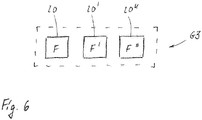
- the different functional units 20, 20', 20" have differently dimensioned fluid mechanical properties F, F ', F "and are each fluid-conducting with one of the pump units 3, 3 ', 3 "and / or one of the throttle units 4, 4', 4" can be connected
- Fig. 4 Kit A can easily be expanded to include the additional group G3.
Landscapes
- Health & Medical Sciences (AREA)
- Vascular Medicine (AREA)
- Engineering & Computer Science (AREA)
- Anesthesiology (AREA)
- Biomedical Technology (AREA)
- Heart & Thoracic Surgery (AREA)
- Hematology (AREA)
- Life Sciences & Earth Sciences (AREA)
- Animal Behavior & Ethology (AREA)
- General Health & Medical Sciences (AREA)
- Public Health (AREA)
- Veterinary Medicine (AREA)
- Physics & Mathematics (AREA)
- Fluid Mechanics (AREA)
- Infusion, Injection, And Reservoir Apparatuses (AREA)
- External Artificial Organs (AREA)
Abstract
Description
- Die Erfindung betrifft ein Kit zur modularen Ausbildung einer medizinischen Pumpvorrichtung zur Förderung eines medizinischen Fluids sowie eine solche medizinische Pumpvorrichtung.
- Medizinische Pumpvorrichtungen sind im Bereich der Medizintechnik allgemein bekannt und zur Verwendung bei einer Infusionstherapie vorgesehen. Die bekannte medizinische Pumpvorrichtung weist eine Pumpeinheit auf, die auch als elastomere Infusionspumpe oder medizinische Elastomerpumpe bezeichnet werden kann. Die Elastomerpumpe weist eine elastomere Membran auf, die ein Pumpvolumen zur Aufnahme und Förderung eines medizinischen Fluids ausbildet. Bei einer Befüllung des Pumpvolumens mit dem medizinischen Fluid wird die elastomere Membran ballonartig elastisch gedehnt. Die auf diese Weise gedehnte Membran bewirkt einen Förderdruck auf das Pumpvolumen. Mittels des Förderdrucks kann das medizinische Fluid beispielsweise in eine fluidleitend mit der Pumpvorrichtung verbindbare Katheterleitung gefördert und somit einem Patienten verabreicht werden. Die bekannte medizinische Pumpvorrichtung weist zudem eine fluidleitend mit dem Pumpvolumen verbundene Drosseleinheit auf. Die Drosseleinheit ist zur Drosselung der Förderung des medizinischen Fluids auf eine nominelle Flussrate eingerichtet und weist hierzu eine strömungsmechanische Drosselwirkung auf. Diese Drosselwirkung ist nicht veränderlich. Bei der bekannten medizinischen Pumpvorrichtung sind die Pumpeinheit und die Drosseleinheit fertigungsseitig unlösbar miteinander zusammengefügt. Hierdurch weist die bekannte medizinische Pumpvorrichtung eine festgelegte Spezifikation im Hinblick auf eine maximal verabreichbare Fluidmenge und eine nominelle Flussrate bei der Verabreichung des medizinischen Fluids auf. Dabei erfordern unterschiedliche medizinische Anwendungsfälle unterschiedliche maximal verabreichbare Fluidmengen und damit unterschiedlich dimensionierte Pumpvolumen sowie unterschiedliche nominelle Flussraten und damit unterschiedlich dimensionierte Drosselwirkungen. Dies führt bei der bekannten medizinischen Pumpvorrichtung dazu, dass diese in unterschiedlichsten Spezifikationen, d.h. mit großer Spezifikationsbreite, bereitgestellt werden muss. Hierdurch werden insbesondere die Fertigung und die Lagerhaltung erschwert.
- Aufgabe der Erfindung ist es, die Ausbildung einer medizinischen Pumpvorrichtung der eingangs genannten Art zu ermöglichen, wobei insbesondere eine vereinfachte Fertigung und eine vereinfachte Lagerhaltung unter Beibehaltung oder Erweiterung der Spezifikationsbreite ermöglicht sein sollen.
- Diese Aufgabe wird durch ein Kit mit den Merkmalen des Anspruchs 1 gelöst.
- Das erfindungsgemäße Kit ist zur modularen Ausbildung einer medizinischen Pumpvorrichtung zur Förderung eines medizinischen Fluids vorgesehen und weist auf
- eine Gruppe mit mehreren unterschiedlichen Pumpeinheiten, die jeweils ein Pumpvolumen zur Aufnahme und Förderung des medizinischen Fluids aufweisen,
- wobei die Pumpeinheiten unterschiedlich dimensionierte Pumpvolumina aufweisen,
- und wobei die Pumpeinheiten jeweils ein erstes Kupplungselement aufweisen, das derart gestaltet ist, dass das jeweilige Pumpvolumen fluidleitend mit einer Drosseleinheit verbindbar ist,
- und eine Gruppe mit mehreren unterschiedlichen Drosseleinheiten, die jeweils zur Drosselung der Förderung des medizinischen Fluids eingerichtet sind,
- wobei die Drosseleinheiten unterschiedlich dimensionierte Drosselwirkungen aufweisen,
- und wobei die Drosseleinheiten jeweils ein zweites Kupplungselement aufweisen, das derart gestaltet ist, dass die jeweilige Drosseleinheit fluidleitend mit einem Pumpvolumen einer der Pumpeinheiten verbindbar ist,
- wobei die Pumpeinheiten und die Drosseleinheiten räumlich voneinander getrennt angeordnet sind.
- Durch die erfindungsgemäße Lösung kann - je nach medizinischen Anwendungsfall - eine medizinische Pumpvorrichtung mit einem für diesen Anwendungsfall erforderlichen Pumpvolumen und einer für diesen Anwendungsfall erforderlichen Flussrate ausgebildet werden. Diese Ausbildung der medizinischen Pumpvorrichtung unter Verwendung des erfindungsgemäßen Kits erfolgt in individualisierter Form endnutzerseitig und insoweit durch einen Patienten oder durch medizinisches Personal. Hierzu wählt die betreffende Person aus der Gruppe der unterschiedlichen Pumpeinheiten eine Pumpeinheit mit dem erforderlichen Pumpvolumen und aus der Gruppe der Drosseleinheiten eine Drosseleinheit mit der erforderlichen Drosselwirkung aus. Hiernach werden die ausgewählte Pumpeinheit und die ausgewählte Drosseleinheit mittels der Kupplungselemente, vorzugsweise unlösbar, fluidleitend miteinander verbunden. Hierdurch ermöglicht die erfindungsgemäße Lösung eine deutlich vereinfachte Fertigung und Lagerhaltung unter Beibehaltung der Spezifikationsbreite oder Erweiterung derselben. Denn es kann sowohl auf die Fertigung als auch auf die Lagerhaltung von medizinischen Pumpvorrichtungen mit unterschiedlichsten Spezifikationen im Hinblick auf eine festgelegte Kombination aus Pumpvolumen und Drosselwirkung verzichtet werden. Zudem ermöglicht die erfindungsgemäße Lösung eine dementsprechend vereinfachte Logistik, da eine reduzierte Anzahl von Artikeln und/oder ein reduziertes Transportvolumen transportiert werden muss. Ein erfindungsgemäßes Kit mit beispielsweise drei unterschiedlichen Pumpeinheiten und drei unterschiedlichen Drosseleinheiten weist sechs Teile auf und ermöglicht eine modulare Ausbildung einer medizinischen Pumpvorrichtung in neun unterschiedlichen Spezifikationen. Dabei sind lediglich sechs Teile - drei Pumpeinheiten und drei Drosseleinheiten - anstelle von neun unterschiedlich spezifizierten medizinischen Pumpvorrichtungen zu fertigen, zu transportieren und zu lagern. Ein erfindungsgemäßes Kit mit beispielsweise vier unterschiedlichen Pumpeinheiten und vier unterschiedlichen Drosseleinheiten weist acht Teile auf und ermöglicht eine modulare Ausbildung einer medizinischen Pumpvorrichtung in 16 unterschiedlichen Spezifikationen. Dabei sind lediglich acht Teile - vier Pumpeinheiten und vier Drosseleinheiten - anstelle von 16 unterschiedlich spezifizierten medizinischen Pumpvorrichtungen zu fertigen, zu transportieren und zu lagern. Ein erfindungsgemäßes Kit mit beispielsweise zehn unterschiedlichen Pumpeinheiten und zehn unterschiedlichen Drosseleinheiten weist 20 Teile auf und ermöglicht eine modulare Ausbildung einer medizinischen Pumpvorrichtung in 100 unterschiedlichen Spezifikationen. Dabei sind lediglich 20 Teile - 10 Pumpeinheiten und 10 Drosseleinheiten - anstelle von 100 unterschiedlich spezifizierten medizinischen Pumpvorrichtungen zu fertigen, zu transportieren und zu lagern. Die Pumpeinheiten sind vorzugsweise derart ausgebildet, dass eine Versorgung mit externer, insbesondere elektrischer, Betriebsenergie zur Förderung des medizinischen Fluids nicht notwendig ist. Vorzugsweise sind die Pumpeinheiten jeweils nach Art einer Elastomerpumpe ausgebildet. Elastomerpumpen sind im Bereich der Medizintechnik als solche grundsätzlich bekannt. Alternativ können die Pumpeinheiten über einen Gasdruck- oder Federspeicher mit Betriebsenergie versorgt werden. Weiter alternativ können die Pumpeinheiten als elektrische und/oder elektronische Pumpeinheiten gestaltet sein, wobei eine Versorgung mit elektrischer Betriebsenergie vorgesehen ist. Bei einer solchen Gestaltung kann die Pumpeinheit ein Fördervolumen aktiv steuern. Die Gruppe der unterschiedlichen Pumpeinheiten weist vorzugsweise eine Vielzahl unterschiedlicher Pumpeinheiten auf. Hierbei meint unterschiedlich baugleich und im Hinblick auf ein Fassungsvermögen des Pumpvolumens unterschiedlich dimensioniert. Deren Pumpvolumina sind vorzugsweise auf ein nominelles Fassungsvermögen zwischen 25 ml und 1000 ml dimensioniert. Beispielsweise können die Pumpvolumina unterschiedlich dimensioniert sein auf nominell 50 ml, 60 ml, 100 ml, 120 ml, 125 ml, 250 ml, 270 ml, 400 ml und/oder 500 ml. Die Drosseleinheiten wirken jeweils vorzugsweise strömungsmechanisch nach Art einer Flussdrossel. Flussdrosseln sind im Bereich der Strömungstechnik als solche grundsätzlich bekannt. Die Gruppe der unterschiedlichen Drosseleinheiten weist vorzugsweise eine Vielzahl von unterschiedlichen Drosseleinheiten auf. Hiermit meint unterschiedlich baugleich und im Hinblick auf die Drosselwirkung unterschiedlich dimensioniert. Die Drosselwirkung kann beispielsweise derart unterschiedlich dimensioniert sein, dass bei der Förderung des medizinischen Fluids eine nominelle Flussrate zwischen 0,5 ml/h und 1.000 ml/h bewirkt ist. Beispielsweise können die Drosselwirkungen unterschiedlich dimensioniert sein auf Flussraten von 2 ml/h, 4 ml/h, 5 ml/h, 10 ml/h, 50 ml/h, 100 ml/h, 175 ml/h, 200 ml/h, 250 ml/h und/oder 500 ml/h. Alternativ oder zusätzlich können die Drosselwirkungen der unterschiedlichen Drosseleinheiten unterschiedlich im Hinblick auf eine Toleranz und/oder Genauigkeit der jeweils erzielbaren Flussrate sein. Mit anderen Worten ausgedrückt, können die Drosseleinheiten unterschiedlich abgestufte Toleranzen und/oder Genauigkeiten der Drosselwirkung aufweisen. Die Drosselwirkung der Drosseleinheiten ist vorzugsweise unveränderlich im Sinne von nutzerseitig nicht einstellbar und/oder nicht steuerbar. Alternativ kann die Drosselwirkung mittels einer entsprechenden Stelleinrichtung einstellbar sein. Weiter alternativ können die Drosseleinheiten als elektrisch und/oder elektronisch steuerbare und/oder regelbare Drosseleinheiten gestaltet sein. Beispielsweise kann eine solche Drosseleinheit als Piezo-Element, das durch eine Kapazität in eine dedizierte Regelstellung gebracht wird, oder als elektronisch ansteuerbares Ventil gestaltet sein. Das erste Kupplungselement und das zweite Kupplungselement sind komplementär zueinander ausgebildet. In einem miteinander verbundenen Zustand bilden die Kupplungselemente eine fluidleitende Verbindung zwischen dem Pumpvolumen und der Drosseleinheit aus. Die Kupplungselemente können insbesondere als Steck- und/oder Schraubkonnektoren ausgebildet sein. Das erfindungsgemäße Kit sieht eine räumlich getrennte Anordnung der Pumpeinheiten und der Drosseleinheiten insoweit vor, als diese nicht fluidleitend miteinander verbunden sind. Die fluidleitende Verbindung erfolgt vielmehr erst endnutzerseitig, beispielsweise durch einen Patienten oder medizinisches Personal, bei einer modularen Ausbildung der medizinischen Pumpvorrichtung unter Verwendung des Kits. Vorzugsweise können die Pumpeneinheiten und die Drosseleinheiten zueinander komplementäre elektrische und/oder elektro-mechanische Schnittstellen aufweisen, über welche im verbundenen Zustand der Schnittstellen Informationen ausgetauscht werden können. Solche Informationen können beispielsweise eine Identifikationsnummer, eine Spezifikation oder dergleichen betreffen. Bei einem Kontaktieren der Schnittstellen kann zudem eine Art Entwertung erfolgen, sofern die Pumpeinheit und/oder die Drosseleinheit als Einmalartikel zur einmaligen Verwendung vorgesehen sind.
- In Ausgestaltung der Erfindung weisen die Pumpeinheiten jeweils eine elastomere Membran auf, die das Pumpvolumen zur Aufnahme und Förderung des medizinischen Fluids ausbildet und in einem wenigstens teilweise mit dem medizinischen Fluid befüllten Zustand derart elastisch gedehnt ist, dass ein Förderdruck auf das Pumpvolumen bewirkt ist. Demnach sind die Pumpeinheiten jeweils nach Art einer Elastomerpumpe ausgebildet. Elastomerpumpen sind im Bereich der Medizintechnik als solche grundsätzlich bekannt und können auch als elastomere Infusionspumpen bezeichnet werden. Dabei ist die Pumpeinheit vorzugsweise derart dimensioniert, dass sie ohne weiteres von einem Patienten am Körper getragen und ohne eine externe Energieversorgung insbesondere im Rahmen einer ambulanten Infusionstherapie verwendbar ist. Die Energie zur Förderung des medizinischen Fluids wird vorzugsweise allein durch die elastisch gedehnte elastomere Membran bereitgestellt.
- In weiterer Ausgestaltung der Erfindung sind das erste Kupplungselement und das zweite Kupplungselement derart komplementär gestaltet, dass eine mittels der Kupplungselemente bewirkte fluidleitende Verbindung unlösbar ist. Die Kupplungselemente dienen demnach einer einmaligen endnutzerseitigen Verbindung der jeweiligen Pumpeinheit mit der jeweiligen Drosseleinheit. Nach einer einmal hergestellten fluidleitenden Verbindung ist diese nicht mehr zerstörungsfrei lösbar. Diese Ausgestaltung der Erfindung wirkt insbesondere einem ungewollten Lösen der fluidleitenden Verbindung entgegen. Hierdurch kann eine verbesserte Patientensicherheit erreicht werden. Die Kupplungselemente können hierzu mit zueinander komplementären Rast- oder Schnappgeometrien versehen sein, die in verbundenem Zustand ein Lösen verhindern.
- In weiterer Ausgestaltung der Erfindung weisen die Drosseleinheiten jeweils ein drittes Kupplungselement auf, das zur fluidleitenden Verbindung der Drosseleinheit und damit der medizinischen Pumpvorrichtung mit einem patientenseitigen Zugang eingerichtet ist. Vorzugsweise ist das dritte Kupplungselement stirnendseitig einer der Drosseleinheit zugeordneten Schlauchleitung angeordnet. Das dritte Kupplungselement ist vorzugsweise in Form eines im Bereich der Medizintechnik grundsätzlich bekannten Fluidkonnektors ausgebildet. Beispielsweise kann das dritte Kupplungselement in Form eines Luer-Konnektors oder eines NRFit-Konnektors ausgebildet sein.
- In weiterer Ausgestaltung der Erfindung weisen die Drosseleinheiten jeweils ein Filterelement auf, das zur Filterung des medizinischen Fluids vorgesehen ist. Das Filterelement ist in einem fluidführenden Querschnitt der Drosseleinheit angeordnet. Mittels des Filterelements kann eine nochmals verbesserte Patientensicherheit erreicht werden, da etwaige partikelförmige Verunreinigungen des medizinischen Fluids bei dessen Förderung durch die Drosseleinheit herausgefiltert werden können. Alternativ oder zusätzlich können die Drosseleinheiten jeweils ein Indikatorelement ausweisen, das zur Anzeige eines Strömungszustands des medizinischen Fluids eingerichtet ist. Bspw. kann das Indikatorelement derart gestaltet sein, dass ein Fluss und ein Nicht-Fluss des Fluids und damit zwei unterschiedliche Strömungszustände anzeigbar sind.
- In weiterer Ausgestaltung der Erfindung weisen die Pumpeinheiten jeweils einen Füllzustand auf, in dem das jeweilige Pumpvolumen mit dem medizinischen Fluid vorbefüllt ist. Vorbefüllt meint, dass das medizinische Fluid bereits bei der produktionsseitigen Bereitstellung des Kits in die Pumpvolumina eingefüllt wurde. Diese Ausgestaltung der Erfindung ist besonders vorteilhaft, wenn die Pumpeinheiten jeweils nach Art einer Elastomerpumpe ausgebildet sind und eine elastomere Membran aufweisen, die das Pumpvolumen ausbildet. Der vorbefüllte Füllzustand der Pumpeinheiten ermöglicht eine vereinfachte Handhabung des Kits, da auf eine nachträgliche, nutzerseitige Befüllung des Pumpvolumens verzichtet werden kann.
- In weiterer Ausgestaltung der Erfindung weisen die Pumpeinheiten jeweils ein Versiegelungselement auf, mittels dessen das jeweilige Pumpvolumen öffenbar fluiddicht versiegelt ist. Das Versiegelungselement dient einem fluiddichten Verschließen des mit dem medizinischen Fluid vorbefüllten Pumpvolumens. Durch diese Versiegelung kann eine verbesserte Hygiene und letztlich eine verbesserte Patientensicherheit bei der Ausbildung der medizinischen Pumpvorrichtung unter Verwendung des Kits erreicht werden. Das Versiegelungselement kann insbesondere in Form einer Kappe, eines Stopfens, eines Schraub- oder Drehverschlusses, eines Sollbruchelements oder dergleichen ausgebildet sein. Dabei kann die Versiegelung form-, kraft- und/oder stoffschlüssig bewirkt sein.
- In weiterer Ausgestaltung der Erfindung weisen die Pumpeinheiten jeweils einen Druckminderer auf, mittels dessen ein Förderdruck des medizinischen Fluids reduzierbar ist. Der Druckminderer ist fluidleitend mit dem Pumpvolumen verbunden. Druckminderer sind im Bereich der Strömungstechnik als solche grundsätzlich bekannt. Der Druckminderer kann auch als Druckminderungsventil oder Reduzierventil bezeichnet werden. Mittels des Druckminderers wird gewährleistet, dass ein auslassseitig an der Pumpeinheit anliegender Druck des medizinischen Fluids einen bestimmten Grenzwert nicht überschreitet. Der Druckminderer wirkt insbesondere einer druckbedingten Überdosierung des medizinischen Fluids entgegen und ermöglicht letztlich eine nochmals verbesserte Patientensicherheit.
- In weiterer Ausgestaltung der Erfindung ist ein weitere Gruppe mit mehreren unterschiedlichen Funktionseinheiten vorgesehen, wobei die Funktionseinheiten unterschiedlich dimensionierte, vorzugsweise strömungsmechanische, Eigenschaften aufweisen, und wobei die Funktionseinheiten jeweils fluidleitend mit einer der Pumpeinheiten und/oder einer der Drosseleinheiten verbindbar sind. Zur fluidleitenden Verbindung mit den Pumpeinheiten und/oder den Drosseleinheiten können die Funktionseinheiten jeweils mit entsprechenden Kupplungselementen versehen sein.
- Die Erfindung betrifft zudem ein Kit zur modularen Ausbildung einer medizinischen Pumpvorrichtung zur Förderung eines medizinischen Fluids, aufweisend wenigstens eine Pumpeinheit, die ein Pumpvolumen zur Aufnahme und Förderung des medizinischen Fluids aufweist, wobei die Pumpeinheit ein erstes Kupplungselement aufweist, das derart gestaltet ist, dass das Pumpvolumen fluidleitend mit einer Drosseleinheit verbindbar ist, und aufweisend wenigstens eine Drosseleinheit, die zur Drosselung der Förderung des medizinischen Fluids eingerichtet ist und hierzu eine Drosselwirkung aufweist, wobei die Drosseleinheit ein zweites Kupplungselement aufweist, das derart gestaltet ist, dass die Drosseleinheit fluidleitend mit dem Pumpvolumen der Pumpeinheit verbindbar ist, wobei die Pumpeinheit und die Drosseleinheit räumlich voneinander getrennt angeordnet sind. Hinsichtlich der gegenständlichen und funktionellen Ausgestaltung der wenigstens einen Pumpeinheit und der wenigstens einen Drosseleinheit gilt das im Zusammenhang mit dem oben beschriebenen Kit aufweisend eine Gruppe bestehend aus mehreren unterschiedlichen Pumpeinheiten und eine Gruppe bestehend aus mehreren unterschiedlichen Drosseleinheiten Gesagte vorliegend in entsprechender Weise. Zur Vermeidung von Wiederholungen wird auf die diesbezügliche Offenbarung ausdrücklich Bezug genommen.
- Die Erfindung betrifft zudem eine medizinische Pumpvorrichtung zur Förderung eines medizinischen Fluids, wobei die medizinische Pumpvorrichtung durch eine modulare Ausbildung unter Verwendung eines Kits nach der vorhergehenden Beschreibung gekennzeichnet ist.
- Weitere Vorteile und Merkmale der Erfindung ergeben sich aus den Ansprüchen sowie aus der nachfolgenden Beschreibung eines bevorzugten Ausführungsbeispiels der Erfindung, das anhand der Zeichnungen dargestellt ist.
- Fig. 1
- zeigt in schematisch stark vereinfachter Darstellung eine Ausführungsform einer erfindungsgemäßen medizinischen Pumpvorrichtung, die unter Verwendung einer Ausführungsform eines erfindungsgemäßen Kits (
Fig. 4 ) modular ausgebildet ist, - Fig. 2
- in schematisch stark vereinfachter Darstellung eine Pumpeinheit und eine Drosseleinheit der medizinischen Pumpvorrichtung nach
Fig. 1 in einem unverbundenen Zustand, - Fig. 3
- in einer weiteren schematisch vereinfachten Darstellung die medizinische Pumpvorrichtung nach den
Fig. 1 und 2 , wobei weitere Gestaltungsmerkmale erkennbar und die Pump- und die Drosseleinheit voneinander getrennt dargestellt sind, - Fig. 4
- in schematisch stark vereinfachter Prinzipdarstellung eine Ausführungsform eines erfindungsgemäßen Kits, unter dessen Verwendung die medizinische Pumpvorrichtung nach den
Fig. 1 bis 3 ausgebildet ist, - Fig. 5
- in einer Darstellungsweise entsprechend
Fig. 4 eine Ausführungsform eines erfindungsgemäßen Kits mit wenigstens einer Pumpeinheit und wenigstens einer Drosseleinheit und - Fig. 6
- in schematisch stark vereinfachter Prinzipdarstellung eine Ausführungsvariante des Kits nach
Fig. 4 , wobei das Kit eine Gruppe mit unterschiedlichen Funktionseinheiten aufweist. - Eine medizinische Pumpvorrichtung 1 nach den
Fig. 1 bis 3 ist zur Förderung eines medizinischen Fluids 2 im Rahmen einer ambulanten und/oder stationären Infusionstherapie vorgesehen. Die medizinische Pumpvorrichtung 1 ist auf noch näher beschriebene Weise unter Verwendung eines Kits A nachFig. 4 modular ausgebildet. Nachfolgend wird zunächst auf die gegenständliche und funktionelle Ausgestaltung der medizinischen Pumpvorrichtung 1 näher eingegangen. - Die medizinische Pumpvorrichtung 1 weist eine Pumpeinheit 3 und eine Drosseleinheit 4 auf.
- Die Pumpeinheit 3 weist ein Pumpvolumen V auf, das zur Aufnahme und Förderung des medizinischen Fluids 2 vorgesehen ist. Dabei ist die Pumpeinheit 3 auf noch näher beschriebene Weise derart gestaltet, dass das medizinische Fluid 2 ohne eine externe, insbesondere elektrische, Energieversorgung mittels der Pumpeinheit 3 förderbar ist. Die Pumpeinheit 3 weist zudem ein erstes Kupplungselement 5 auf. Das erste Kupplungselement ist derart gestaltet, dass das Pumpvolumen V fluidleitend mit der Drosseleinheit 4 verbindbar ist. Das erste Kupplungselement 5 ist vorliegend stirnendseitig einer Fluidleitung 6 angeordnet, die an einem dem ersten Kupplungselement 5 abgewandten Stirnende fluidleitend mit dem Pumpvolumen V verbunden ist.
- Die Drosseleinheit 4 ist zur Drosselung der mittels der Pumpeinheit 3 bewirkten Förderung des medizinischen Fluids 2 eingerichtet. Hierzu weist die Drosseleinheit 4 ein Drosselelement 7 auf. Das Drosselelement 7 ist derart gestaltet, dass die Förderung des medizinischen Fluids 2 auf eine festgelegte Flussrate begrenzt ist. Hierzu weist das Drosselelement 7 eine entsprechende strömungstechnische Drosselwirkung W auf. Zudem weist die Drosseleinheit 4 ein zweites Kupplungselement 8 auf, das zur fluidleitenden Verbindung mit dem ersten Kupplungselement 5 der Pumpeinheit 3 vorgesehen ist. Zu diesem Zweck sind die Kupplungselemente 5, 8 komplementär zueinander ausgebildet. In dem anhand
Fig. 1 ersichtlichen Zustand sind die Kupplungselemente 5, 8 fluidleitend miteinander verbunden. In dem anhandFig. 2 ersichtlichen Zustand sind die Kupplungselemente 5, 8 demgegenüber voneinander getrennt. Das zweite Kupplungselement 8 ist stirnendseitig einer Fluidleitung 9 der Drosseleinheit 4 angeordnet. Die Fluidleitung 9 bildet eine fluidleitende Verbindung zwischen dem zweiten Kupplungselement 8 und dem Drosselelement 7 aus. - Das erste Kupplungselement 5 und das zweite Kupplungselement 8 sind vorliegend derart komplementär gestaltet, dass eine mittels der Kupplungselemente 5, 8 bewirkte fluidleitende Verbindung, wie sie anhand
Fig. 1 ersichtlich ist, nicht zerstörungsfrei lösbar ist. Hierzu können die Kupplungselemente 5, 8 mit einer entsprechend gestalteten Rast- und/oder Schnappgeometrie versehen sein. - Weitere gegenständliche und funktionelle Merkmale der medizinischen Pumpvorrichtung 1 sind anhand der detaillierteren Darstellung der
Fig. 3 ersichtlich. Dort ist erkennbar, dass die Pumpeinheit 3 eine elastomere Membran 10 aufweist, die das Pumpvolumen V ausbildet. Dabei weist die Pumpeinheit 3 einen Füllzustand auf, in dem das Pumpvolumen V mit dem medizinischen Fluid 2 befüllt ist. Das medizinische Fluid 2 ist vorliegend eine nicht näher bezeichnete Medikamentenflüssigkeit. In diesem Füllzustand ist die elastomere Membran 10 infolge einer mechanischen Einwirkung des medizinischen Fluids 2 ballonartig weichelastisch gedehnt. Dabei ist die elastomere Membran 10 anhandFig. 3 aus zeichnerischen Gründen mit einer überhöhten Wandungsstärke dargestellt. Demgegenüber ist die elastomere Membran 10 in einem nicht mit medizinischen Fluid 2 befüllten Zustand schlaff oder jedenfalls weniger stark elastisch gedehnt. Zum Befüllen des Pumpvolumens V mit dem medizinischen Fluid 2 ist vorliegend ein wiederverschließbarer Einfüllstutzen 11 vorgesehen, der auf grundsätzlich bekannte Weise fluiddicht an die elastomere Membran 10 angeschlossen ist. Die elastisch gedehnte elastomere Membran 10 bewirkt einen Förderdruck p auf das Pumpvolumen V. Mittels des auf diese Weise bewirkten Förderdrucks p ist das medizinische Fluid 2 über einen auf grundsätzlich bekannte Weise fluiddicht an die elastomere Membran 10 angeschlossenen Durchlassstutzen 12 aus dem Pumpvolumen V in die Fluidleitung 6 förderbar. Die Fluidleitung 6 ist auf grundsätzlich bekannte Weise fluidleitend an den Durchlassstutzen 12 angeschlossen. Vorliegend ist die Fluidleitung in Form eines biegeflexiblen Schlauchabschnitts 6 ausgebildet, wobei das erste Kupplungselement 5 stirnendseitig an dem Schlauchabschnitt 6 angeordnet ist. Die Pumpeinheit 3 ist vorliegend nach Art einer medizinischen Elastomerpumpe ausgebildet. Solche Pumpen sind im Bereich der Medizintechnik als solche grundsätzlich bekannt und können auch als elastomere Infusionspumpen bezeichnet werden. - Zudem ist anhand
Fig. 3 ersichtlich, dass die Fluidleitung 9 in Form eines biegeflexiblen Schlauchabschnitts ausgebildet ist. Dabei ist das zweite Kupplungselement 8 stirnendseitig des Schlauchabschnitts 9 angeordnet und in dem anhandFig. 3 ersichtlichen Zustand nicht mit dem ersten Kupplungselement 5 verbunden. An einem dem zweiten Kupplungselement 8 abgewandten Stirnendbereich des Schlauchabschnitts 9 ist ein drittes Kupplungselement 13 angeordnet. Das dritte Kupplungselement 13 ist zur fluidleitenden Verbindung der Drosseleinheit 4 und - im fluidleitend miteinander verbundenen Zustand der Kupplungselemente 5, 8 - der medizinischen Pumpvorrichtung 1 mit einem zeichnerisch nicht näher dargestellten patientenseitigen Zugang eingerichtet. Vorliegend ist lediglich ein dem Patientenzugang zugeordneter Fluidleitungsabschnitt 14 strichliert und teilweise abgeschnitten angedeutet. Das dritte Kupplungselement 13 ist in Form eines Luer-Konnektors ausgebildet, wie er im Bereich der Medizintechnik grundsätzlich bekannt ist. Bei einer zeichnerisch nicht näher dargestellten Ausführungsform kann das dritte Kupplungselement 13 in Form eines NRFit-Konnektors ausgebildet sein. Weitere Komponenten der Drosseleinheit 4, insbesondere das Drosselelement 7, sind anhandFig. 3 lediglich schematisch stark vereinfacht und insoweit strichliert dargestellt. - Wie weiter insbesondere anhand der
Fig. 1 und 2 ersichtlich ist, weist die Drosseleinheit ein Filterelement 15 auf. Das Filterelement 15 ist der Fluidleitung 9 zugeordnet, wird bei einer Förderung des medizinischen Fluids 2 mit demselben durchspült und dient einer Filterung etwaiger partikelförmiger Verunreinigungen aus dem medizinischen Fluid 2. - Zudem weist die Pumpeinheit 3 - in dem anhand der
Fig. 2 und3 nicht mit der Drosseleinheit 4 verbunden Zustand - ein Versiegelungselement 16 auf. Das Versiegelungselement 16 ist vorliegend dem ersten Kupplungselement 5 zugeordnet, was jedoch nicht zwingend der Fall sein muss. Das Versiegelungselement 16 dient einer fluiddichten Versiegelung des Pumpvolumens V. Demnach ist das Pumpvolumen V in dem anhand derFig. 2 und3 ersichtlichen Zustand mittels des Versiegelungselements 16 öffenbar fluiddicht versiegelt. Das Versiegelungselement 16 ist vorliegend nach Art eines Stopfens ausgebildet, der stirnendseitig fluiddicht in das erste Kupplungselement 5 eingepasst ist. Bei einer zeichnerisch nicht näher dargestellten Ausführungsform kann das Versiegelungselement 16 auch derart gestaltet sein, dass das erste Kupplungselement 5 öffenbar stoffschlüssig fluiddicht mit dem Versiegelungselement 16 versiegelt ist. Vor einer manuellen Verbindung der Kupplungselemente 5, 8 wird das Versiegelungselement 16 manuell entfernt und somit das Pumpvolumen V entsiegelt. - Zudem weist die Pumpeinheit 3 einen Druckminderer 17 auf. Der Druckminderer 17 ist der Fluidleitung 6 zugeordnet und wird bei einer Förderung des medizinischen Fluids 2 mit demselben durchspült. Druckminderer sind im Bereich der Fluidtechnik als solche grundsätzlich bekannt. Dabei ist der Druckminderer 17 anhand der Figuren lediglich stark vereinfacht schematisch dargestellt. Anhand
Fig. 3 ist gezeigt, dass der Druckminderer 17 vorliegend in den Durchlassstutzen 12 integriert ist. Dies ist jedoch nicht zwingend der Fall. Mittels des Druckminderers ist der Förderdruck p auf einen vorbestimmten, insbesondere konstanten, Druck reduzierbar. - Die medizinische Pumpvorrichtung 1 ist unter Verwendung des anhand der Prinzipskizze der
Fig. 4 gezeigten Kits A modular ausgebildet. - Das Kit A weist eine Gruppe G1 mit mehreren unterschiedlichen Pumpeinheiten 3, 3', 3" auf. Die Pumpeinheiten 3, 3', 3" weisen unterschiedlich dimensionierte Pumpvolumina V, V', V" auf. Vorliegend besteht die Gruppe G1 aus drei unterschiedlichen Pumpeinheiten 3, 3', 3". Hiervon abweichend kann die Gruppe G1 auch aus lediglich zwei unterschiedlichen Pumpeinheiten oder wesentlich mehr als den gezeigten drei Pumpeinheiten 3, 3', 3" bestehen. Das Pumpvolumen V der Pumpeinheit 3 beträgt vorliegend 60 ml. Das Pumpvolumen V' der Pumpeinheit 3' beträgt vorliegend 120 ml. Das Pumpvolumen V" der Pumpeinheit 3" beträgt vorliegend 270 ml. Mit anderen Worten ist die Pumpeinheit 3 zur Verabreichung von 60 ml, die Pumpeinheit 3' von 120 ml und die Pumpeinheit 3" zur Verabreichung von 270 ml des medizinischen Fluids 2 eingerichtet. Im Übrigen gilt im Hinblick auf die gegenständliche und funktionelle Ausgestaltung der Pumpeinheiten 3' und 3" das zur Pumpeinheit 3 insbesondere in Zusammenhang mit den
Fig. 1 bis 3 Offenbarte in entsprechender Weise, so dass zur Vermeidung von Wiederholungen auf die diesbezügliche Offenbarung verwiesen wird. - Das Kit A weist zudem eine Gruppe G2 mit mehreren unterschiedlichen Drosseleinheiten 4, 4', 4" auf. Die Drosseleinheiten 4, 4', 4" weisen unterschiedlich dimensionierte Drosselwirkungen W, W', W" auf. Vorliegend beträgt eine mit der Drosselwirkung W korrespondierende Flussrate 5 ml/h, eine mit der Drosselwirkung W' korrespondierende Flussrate 4 ml/h und eine mit der Drosselwirkung W" korrespondierende Flussrate 2 ml/h. Im Übrigen gilt im Hinblick auf die gegenständliche und funktionelle Gestaltung der Drosseleinheiten 4' und 4" das zur Drosseleinheit 4 Offenbarte in entsprechender Weise, so dass zur Vermeidung von Wiederholungen auf die diesbezügliche Offenbarung verwiesen wird. Die Gruppe G2 umfasst vorliegend die drei unterschiedlichen Drosseleinheiten 4, 4', 4". Hiervon abweichend kann die Gruppe G2 auch lediglich zwei unterschiedliche Drosseleinheiten oder deutlich mehr als die gezeigten drei Drosseleinheiten 4, 4', 4" aufweisen.
- Bei einer nicht gezeigten Ausführungsform können die Drosselwirkungen der Drosseleinheiten unterschiedlich im Hinblick auf eine Toleranz und/oder Genauigkeit der erzielbaren Flussraten sein.
- Die Pumpeinheiten 3, 3', 3" und die Drosseleinheiten 4, 4', 4" sind innerhalb des Kits A räumlich voneinander getrennt angeordnet, was anhand der strichlierten Linie L schematisch angedeutet ist. Demnach sind die Pumpeinheiten 3, 3', 3" und die Drosseleinheiten 4, 4', 4" innerhalb des Kits A nicht fluidleitend miteinander verbunden. Das Kit A weist vorliegend eine Verpackungsanordnung V auf, in der die Gruppen G1, G2 gemeinsam verpackt sind. Dies schließt nicht aus, dass die Gruppen G1, G2 und/oder die einzelnen Pumpeinheiten 3, 3', 3" und die einzelnen Drosseleinheiten 4, 4', 4" jeweils zusätzlich gesondert verpackt sind. Die Verpackungsanordnung V ist anhand
Fig. 4 lediglich strichliert angedeutet. - Das Kit A dient einer endnutzerseitigen modularen Ausbildung insbesondere der medizinischen Pumpvorrichtung 1 nach den
Fig. 1 bis 3 . Dabei ermöglicht die vorliegende Gestaltung des Kits A die Ausbildung 9 unterschiedlicher Spezifikationen im Hinblick auf eine Kombination der Pumpvolumina V, V', V" und der Drosselwirkungen W, W', W" bzw. der jeweils hiermit korrespondierenden Flussraten. Dementsprechend ermöglicht das Kit A einem Endnutzer, beispielsweise einem Patienten oder medizinischen Personal, eine anwendungsfallgerechte modulare Ausbildung einer auf den spezifischen Anwendungsfall angepassten medizinischen Pumpvorrichtung. Denn je nachdem, ob der Anwendungsfall die Verabreichung einer geringeren oder größeren Menge des medizinischen Fluids 2 und eine kürzere oder längere Verabreichungsdauer erfordert, kann der Endnutzer dementsprechend hieran angepasst eine der Pumpeinheiten 3, 3', 3" mit einer der Drosseleinheiten 4, 4', 4" kombinieren und mittels der Kupplungselemente 5, 8 (vgl.Fig. 1 bis 3 ) miteinander verbinden. Beispielsweise ermöglicht die vorliegende Kombination des auf 60 ml bemessenen Pumpvolumens V und der auf eine Flussrate von 5 ml/h bemessenen Drosselwirkung W eine Infusionsdauer von 12 h. Ist hiervon abweichend beispielsweise eine Infusionsdauer von 15 h oder 30 h und hierbei eine Verabreichung von 60 ml des medizinischen Fluids 2 erforderlich, kann der Endnutzer die Pumpeinheit 3 mit der Drosseleinheit 4' bzw. der Drosseleinheit 4" kombinieren. - Bei der nicht gezeigten Ausführungsform kann eine anwendungsfallgerechte Auswahl im Hinblick auf die Genauigkeit der Drosselwirkung erfolgen. Erlaubt ein Anwendungsfall beispielsweise eine vergleichsweise große Schwankung der resultierenden Infusionsdauer, kann der Endnutzer eine Drosseleinheit mit vergleichsweise geringer Genauigkeit der erzielbaren Flussrate auswählen.
- Anhand
Fig. 5 ist ein Kit B gezeigt. Mittels des Kits B ist die medizinische Pumpvorrichtung 1 nach denFig. 1 bis 3 modular ausbildbar. Hierzu weist das Kit B die Pumpeinheit 3 und die Drosseleinheit 4 auf. Zur Vermeidung von Wiederholungen wird auf das zu Kit A Offenbarte verwiesen, das in entsprechender Weise für Kit B gilt. Das Kit B unterscheidet sich lediglich dahingehend von dem Kit A, dass anstelle der Gruppen G1, G2 mit mehreren Pumpeinheiten bzw. Drosseleinheiten lediglich wenigstens die eine Pumpeinheit 3 und die wenigstens eine Drosseleinheit 4 umfasst ist. - Anhand
Fig. 6 ist eine Gruppe G3 mit mehreren unterschiedlichen Funktionseinheiten 20, 20', 20" ersichtlich. Die unterschiedlichen Funktionseinheiten 20, 20', 20" weisen unterschiedlich dimensionierte strömungsmechanische Eigenschaften F, F', F" und sind jeweils fluidleitend mit einer der Pumpeinheiten 3, 3', 3" und/oder einer der Drosseleinheiten 4, 4', 4" verbindbar. Demnach ist das anhandFig. 4 ersichtliche Kit A vereinfacht ausgedrückt um die weitere Gruppe G3 erweiterbar.
Claims (11)
- Kit (A) zur modularen Ausbildung einer medizinischen Pumpvorrichtung (1) zur Förderung eines medizinischen Fluids (2), aufweisend- eine Gruppe (G1) mit mehreren unterschiedlichen Pumpeinheiten (3, 3', 3"), die jeweils ein Pumpvolumen (V, V', V") zur Aufnahme und Förderung des medizinischen Fluids (2) aufweisen,- wobei die Pumpeinheiten (3, 3', 3") unterschiedlich dimensionierte Pumpvolumina (V, V', V") aufweisen,- und wobei die Pumpeinheiten (3, 3', 3") jeweils ein erstes Kupplungselement (5) aufweisen, das derart gestaltet ist, dass das jeweilige Pumpvolumen (V, V', V") fluidleitend mit einer Drosseleinheit (4, 4', 4") verbindbar ist,- und eine Gruppe (G2) mit mehreren unterschiedlichen Drosseleinheiten (4, 4', 4"), die jeweils zur Drosselung der Förderung des medizinischen Fluids (2) eingerichtet sind,- wobei die Drosseleinheiten (4, 4', 4") unterschiedlich dimensionierte Drosselwirkungen (W, W', W") aufweisen,- und wobei die Drosseleinheiten (4, 4', 4") jeweils ein zweites Kupplungselement (8) aufweisen, das derart gestaltet ist, dass die jeweilige Drosseleinheit (4, 4', 4") fluidleitend mit einem Pumpvolumen (V, V', V") einer der Pumpeinheiten (3, 3', 3") verbindbar ist,- wobei die Pumpeinheiten (3, 3', 3") und die Drosseleinheiten (4, 4', 4") räumlich voneinander getrennt angeordnet sind.
- Kit (A) nach Anspruch 1, dadurch gekennzeichnet, dass die Pumpeinheiten (3, 3', 3") jeweils eine elastomere Membran (10) aufweisen, die das Pumpvolumen (V, V', V") zur Aufnahme und Förderung des medizinischen Fluids (2) ausbildet und in einem wenigstens teilweise mit dem medizinischen Fluid (2) befüllten Zustand derart elastisch gedehnt ist, dass ein Förderdruck (p) auf das Pumpvolumen (V, V', V") bewirkt ist.
- Kit (A) nach Anspruch 1 oder 2, dadurch gekennzeichnet, dass das erste Kupplungselement (5) und das zweite Kupplungselement (8) derart komplementär gestaltet sind, dass eine mittels der Kupplungselemente (5, 8) bewirkte fluidleitende Verbindung unlösbar ist.
- Kit (A) nach einem der vorhergehenden Ansprüche, dadurch gekennzeichnet, dass die Drosseleinheiten (4, 4', 4") jeweils ein drittes Kupplungselement (13) aufweisen, das zur fluidleitenden Verbindung der Drosseleinheit (4, 4', 4") und damit der medizinischen Pumpvorrichtung (1) mit einem patientenseitigen Zugang eingerichtet ist.
- Kit (A) nach einem der vorhergehenden Ansprüche, dadurch gekennzeichnet, dass die Drosseleinheiten (4, 4', 4") jeweils ein Filterelement (15) aufweisen, das zur Filterung des medizinischen Fluids (2) vorgesehen ist.
- Kit (A) nach einem der vorhergehenden Ansprüche, dadurch gekennzeichnet, dass die Pumpeinheiten (3, 3', 3") jeweils einen Füllzustand aufweisen, in dem das jeweilige Pumpvolumen (V, V', V") mit dem medizinischen Fluid (2) vorbefüllt ist.
- Kit (A) nach Anspruch 6, dadurch gekennzeichnet, dass die Pumpeinheiten (3, 3', 3") jeweils ein Versiegelungselement (16) aufweisen, mittels dessen das jeweilige Pumpvolumen (V, V', V") öffenbar fluiddicht versiegelt ist.
- Kit (A) nach einem der vorhergehenden Ansprüche, dadurch gekennzeichnet, dass die Pumpeinheiten (3, 3', 3") jeweils einen Druckminderer (17) aufweisen, mittels dessen ein Förderdruck (p) des medizinischen Fluids (2) reduzierbar ist.
- Kit (A) nach einem der vorhergehenden Ansprüche, dadurch gekennzeichnet, dass eine weitere Gruppe (G3) mit mehreren unterschiedlichen Funktionseinheiten (20, 20', 20") vorgesehen ist, wobei die Funktionseinheiten (20, 20', 20") unterschiedlich dimensionierte, vorzugsweise strömungsmechanische, Eigenschaften (F, F', F") aufweisen, und wobei die Funktionseinheiten (20, 20', 20") jeweils fluidleitend mit einer der Pumpeinheiten (3, 3', 3") und/oder einer der Drosseleinheiten (4, 4', 4") verbindbar sind.
- Kit (B) zur modularen Ausbildung einer medizinischen Pumpvorrichtung (1) zur Förderung eines medizinischen Fluids (2), aufweisend- wenigstens eine Pumpeinheit (3), die ein Pumpvolumen (V) zur Aufnahme und Förderung des medizinischen Fluids (2) aufweist,- wobei die Pumpeinheit (3) ein erstes Kupplungselement (5) aufweist, das derart gestaltet ist, dass das Pumpvolumen (V) fluidleitend mit einer Drosseleinheit (4) verbindbar ist,- und wenigstens eine Drosseleinheit (4), die zur Drosselung der Förderung des medizinischen Fluids (2) eingerichtet ist und hierzu eine Drosselwirkung (W) aufweist,- wobei die Drosseleinheit (4) ein zweites Kupplungselement (8) aufweist, das derart gestaltet ist, dass die Drosseleinheit (4) fluidleitend mit dem Pumpvolumen (V) der Pumpeinheit verbindbar ist,- wobei die Pumpeinheit (3) und die Drosseleinheit (4) räumlich voneinander getrennt angeordnet sind.
- Medizinische Pumpvorrichtung (1) zur Förderung eines medizinischen Fluids (2), gekennzeichnet durch eine modulare Ausbildung unter Verwendung eines Kits (A) nach einem der Ansprüche 1 bis 9 oder eines Kits (B) nach Anspruch 10.
Applications Claiming Priority (1)
| Application Number | Priority Date | Filing Date | Title |
|---|---|---|---|
| DE102018216508.4A DE102018216508A1 (de) | 2018-09-26 | 2018-09-26 | Kit zur modularen Ausbildung einer medizinischen Pumpvorrichtung sowie medizinische Pumpvorrichtung |
Publications (2)
| Publication Number | Publication Date |
|---|---|
| EP3628345A1 true EP3628345A1 (de) | 2020-04-01 |
| EP3628345B1 EP3628345B1 (de) | 2022-10-05 |
Family
ID=67551290
Family Applications (1)
| Application Number | Title | Priority Date | Filing Date |
|---|---|---|---|
| EP19190520.7A Active EP3628345B1 (de) | 2018-09-26 | 2019-08-07 | Kit zur modularen ausbildung einer medizinischen pumpvorrichtung sowie medizinische pumpvorrichtung |
Country Status (4)
| Country | Link |
|---|---|
| US (1) | US20200093986A1 (de) |
| EP (1) | EP3628345B1 (de) |
| CN (1) | CN110947049B (de) |
| DE (1) | DE102018216508A1 (de) |
Citations (4)
| Publication number | Priority date | Publication date | Assignee | Title |
|---|---|---|---|---|
| US4925444A (en) * | 1987-08-07 | 1990-05-15 | Baxter Travenol Laboratories, Inc. | Closed multi-fluid delivery system and method |
| US20030208158A1 (en) * | 2002-05-06 | 2003-11-06 | Lampropoulos Fred P. | Modularized infusion pump apparatus |
| US20150374911A1 (en) * | 2013-02-15 | 2015-12-31 | Repro-Med Systems, Inc. | Multi-flow universal tubing set |
| US20170136177A1 (en) * | 2015-11-12 | 2017-05-18 | Zyno Medical, LLC. | Modular Medical Pump System |
Family Cites Families (16)
| Publication number | Priority date | Publication date | Assignee | Title |
|---|---|---|---|---|
| US4424056A (en) * | 1981-11-27 | 1984-01-03 | Alza Corporation | Parenteral administration |
| US5419771A (en) * | 1989-06-16 | 1995-05-30 | Science Incorporated | Fluid delivery apparatus and support assembly |
| US5284481A (en) * | 1992-12-02 | 1994-02-08 | Block Medical, Inc. | Compact collapsible infusion apparatus |
| US5788674A (en) * | 1996-03-05 | 1998-08-04 | Medication Delivery Devices, Inc. | Apparatus and method for limiting free-flow in an infusion system |
| US7927313B2 (en) * | 2004-05-27 | 2011-04-19 | Baxter International Inc. | Medical device configuration based on recognition of identification information |
| US7935104B2 (en) * | 2005-11-07 | 2011-05-03 | Medingo, Ltd. | Systems and methods for sustained medical infusion and devices related thereto |
| US20070156089A1 (en) * | 2005-12-29 | 2007-07-05 | George Yu | Multi-channel rotary peristaltic infusion pump |
| US8172799B2 (en) * | 2007-01-10 | 2012-05-08 | Acist Medical Systems, Inc. | Volumetric pump |
| US8215157B2 (en) * | 2007-10-04 | 2012-07-10 | Baxter International Inc. | System and method for measuring liquid viscosity in a fluid delivery system |
| US20110202034A1 (en) * | 2010-02-17 | 2011-08-18 | Estill Medical Technologies, Inc. | Modular medical fluid heating apparatus |
| US9433728B2 (en) * | 2013-03-01 | 2016-09-06 | Bayer Healthcare Llc | Valveless pharmaceutical infusion system |
| RU2676427C2 (ru) * | 2014-09-10 | 2018-12-28 | Цито365 Аб | Клапан для введения жидких лекарственных средств и способ управления таким клапаном |
| EP3088021A1 (de) * | 2015-04-27 | 2016-11-02 | Fresenius Vial SAS | Infusionsbasismodul mit mehreren anschliessbaren kontrollmodulen |
| CN107847671B (zh) * | 2015-07-20 | 2021-01-05 | 费森尤斯维尔公司 | 用于执行连续输液过程的方法及系统 |
| WO2018022204A1 (en) * | 2016-07-25 | 2018-02-01 | Smiths Medical Asd, Inc. | Group coordination of operational features of a plurality of medical devices |
| CN206152004U (zh) * | 2016-08-15 | 2017-05-10 | 浙江伏尔特医疗器械股份有限公司 | 多囊驱动控制输注泵 |
-
2018
- 2018-09-26 DE DE102018216508.4A patent/DE102018216508A1/de not_active Withdrawn
-
2019
- 2019-08-07 EP EP19190520.7A patent/EP3628345B1/de active Active
- 2019-09-13 US US16/569,981 patent/US20200093986A1/en not_active Abandoned
- 2019-09-16 CN CN201910871309.0A patent/CN110947049B/zh active Active
Patent Citations (4)
| Publication number | Priority date | Publication date | Assignee | Title |
|---|---|---|---|---|
| US4925444A (en) * | 1987-08-07 | 1990-05-15 | Baxter Travenol Laboratories, Inc. | Closed multi-fluid delivery system and method |
| US20030208158A1 (en) * | 2002-05-06 | 2003-11-06 | Lampropoulos Fred P. | Modularized infusion pump apparatus |
| US20150374911A1 (en) * | 2013-02-15 | 2015-12-31 | Repro-Med Systems, Inc. | Multi-flow universal tubing set |
| US20170136177A1 (en) * | 2015-11-12 | 2017-05-18 | Zyno Medical, LLC. | Modular Medical Pump System |
Also Published As
| Publication number | Publication date |
|---|---|
| CN110947049A (zh) | 2020-04-03 |
| CN110947049B (zh) | 2024-02-06 |
| US20200093986A1 (en) | 2020-03-26 |
| DE102018216508A1 (de) | 2020-03-26 |
| EP3628345B1 (de) | 2022-10-05 |
Similar Documents
| Publication | Publication Date | Title |
|---|---|---|
| DE10020689B4 (de) | System zum Schutz implantierbarer Medikamenten-Abgabegeräte vor einem Überfüllen | |
| EP0401515B1 (de) | Implantierbare Vorrichtung zur dosierten Abgabe von Medikamenten in den menschlichen Körper | |
| DE69323739T2 (de) | Arzneimittel infusionsvorrichtung | |
| DE69104143T2 (de) | Infusionsvorrichtung für Flüssigkeiten. | |
| DE69232695T2 (de) | Nadelfreier, intravenöser adapter | |
| EP2060287B1 (de) | Medikamentenzuführungssystem für CED (Convection Enhanced Delivery)-Katheterinfusionen | |
| DE102010060469B3 (de) | Behälteranordnung und Verfahren zum Füllen von flexiblen Einwegbeuteln | |
| DE60319564T2 (de) | Vorrichtung zur injektion von medizinischen substanzen | |
| DE69726600T2 (de) | Vorrichtung zur arzneimittelverabreichung | |
| DE4037641A1 (de) | Katheter | |
| EP1980282A1 (de) | Medikamentenreservoir und Vorrichtung zur automatisierten Abgabe eines flüssigen Medikaments | |
| EP0660727B1 (de) | Sicherheitsverbinder für die infusionstherapie | |
| DE102009004461A1 (de) | Infusionsbesteck mit integriertem 3-Wege-Hahn zur Infusionsvorbereitung und Zuspritzung (Chamber Spike vented/not vented) | |
| DE102012102273A1 (de) | Vorrichtung zur Zuführung und Dosierung eines Fluids für medizinische Zwecke | |
| DE102010047747B4 (de) | Einwegeventil für ein Infusionsbesteck | |
| DE19642234C1 (de) | Implantierbare Infusionspumpe | |
| WO1989002764A1 (fr) | Agencement de clapet antiretour | |
| EP1745812B1 (de) | Ventil für ein Fluid, insbesondere zur Verwendung in einer mechanisch betriebenen Flüssigkeitspumpe | |
| EP3628345B1 (de) | Kit zur modularen ausbildung einer medizinischen pumpvorrichtung sowie medizinische pumpvorrichtung | |
| EP1980283A1 (de) | Medikamentenreservoir und Vorrichtung zur automatisierten Abgabe eines flüssigen Medikaments | |
| DE102020210986A1 (de) | Infusions- oder Transfusionsbesteck und System umfassend ein Infusions- oder Transfusionsbesteck | |
| DE202017107087U1 (de) | Behältnis zur Bereitstellung patientenspezifischer Arzneimittel | |
| EP3593835A1 (de) | Infusionsanordnung zur verabreichung eines medizinischen fluids | |
| EP3890804B1 (de) | Infusionsanordnung zur verabreichung eines medizinischen fluids | |
| DE102018124003B3 (de) | Gasdruckbetriebene Infusionspumpe zum Applizieren einer Mehrzahl von Medikamenten |
Legal Events
| Date | Code | Title | Description |
|---|---|---|---|
| PUAI | Public reference made under article 153(3) epc to a published international application that has entered the european phase |
Free format text: ORIGINAL CODE: 0009012 |
|
| STAA | Information on the status of an ep patent application or granted ep patent |
Free format text: STATUS: THE APPLICATION HAS BEEN PUBLISHED |
|
| AK | Designated contracting states |
Kind code of ref document: A1 Designated state(s): AL AT BE BG CH CY CZ DE DK EE ES FI FR GB GR HR HU IE IS IT LI LT LU LV MC MK MT NL NO PL PT RO RS SE SI SK SM TR |
|
| AX | Request for extension of the european patent |
Extension state: BA ME |
|
| STAA | Information on the status of an ep patent application or granted ep patent |
Free format text: STATUS: REQUEST FOR EXAMINATION WAS MADE |
|
| 17P | Request for examination filed |
Effective date: 20200921 |
|
| RBV | Designated contracting states (corrected) |
Designated state(s): AL AT BE BG CH CY CZ DE DK EE ES FI FR GB GR HR HU IE IS IT LI LT LU LV MC MK MT NL NO PL PT RO RS SE SI SK SM TR |
|
| STAA | Information on the status of an ep patent application or granted ep patent |
Free format text: STATUS: EXAMINATION IS IN PROGRESS |
|
| 17Q | First examination report despatched |
Effective date: 20210210 |
|
| GRAP | Despatch of communication of intention to grant a patent |
Free format text: ORIGINAL CODE: EPIDOSNIGR1 |
|
| STAA | Information on the status of an ep patent application or granted ep patent |
Free format text: STATUS: GRANT OF PATENT IS INTENDED |
|
| INTG | Intention to grant announced |
Effective date: 20220506 |
|
| GRAS | Grant fee paid |
Free format text: ORIGINAL CODE: EPIDOSNIGR3 |
|
| GRAA | (expected) grant |
Free format text: ORIGINAL CODE: 0009210 |
|
| STAA | Information on the status of an ep patent application or granted ep patent |
Free format text: STATUS: THE PATENT HAS BEEN GRANTED |
|
| AK | Designated contracting states |
Kind code of ref document: B1 Designated state(s): AL AT BE BG CH CY CZ DE DK EE ES FI FR GB GR HR HU IE IS IT LI LT LU LV MC MK MT NL NO PL PT RO RS SE SI SK SM TR |
|
| REG | Reference to a national code |
Ref country code: GB Ref legal event code: FG4D Free format text: NOT ENGLISH |
|
| REG | Reference to a national code |
Ref country code: CH Ref legal event code: EP |
|
| REG | Reference to a national code |
Ref country code: AT Ref legal event code: REF Ref document number: 1522345 Country of ref document: AT Kind code of ref document: T Effective date: 20221015 |
|
| REG | Reference to a national code |
Ref country code: DE Ref legal event code: R096 Ref document number: 502019005810 Country of ref document: DE |
|
| REG | Reference to a national code |
Ref country code: IE Ref legal event code: FG4D Free format text: LANGUAGE OF EP DOCUMENT: GERMAN |
|
| REG | Reference to a national code |
Ref country code: LT Ref legal event code: MG9D |
|
| REG | Reference to a national code |
Ref country code: NL Ref legal event code: MP Effective date: 20221005 |
|
| PG25 | Lapsed in a contracting state [announced via postgrant information from national office to epo] |
Ref country code: NL Free format text: LAPSE BECAUSE OF FAILURE TO SUBMIT A TRANSLATION OF THE DESCRIPTION OR TO PAY THE FEE WITHIN THE PRESCRIBED TIME-LIMIT Effective date: 20221005 |
|
| PG25 | Lapsed in a contracting state [announced via postgrant information from national office to epo] |
Ref country code: SE Free format text: LAPSE BECAUSE OF FAILURE TO SUBMIT A TRANSLATION OF THE DESCRIPTION OR TO PAY THE FEE WITHIN THE PRESCRIBED TIME-LIMIT Effective date: 20221005 Ref country code: PT Free format text: LAPSE BECAUSE OF FAILURE TO SUBMIT A TRANSLATION OF THE DESCRIPTION OR TO PAY THE FEE WITHIN THE PRESCRIBED TIME-LIMIT Effective date: 20230206 Ref country code: NO Free format text: LAPSE BECAUSE OF FAILURE TO SUBMIT A TRANSLATION OF THE DESCRIPTION OR TO PAY THE FEE WITHIN THE PRESCRIBED TIME-LIMIT Effective date: 20230105 Ref country code: LT Free format text: LAPSE BECAUSE OF FAILURE TO SUBMIT A TRANSLATION OF THE DESCRIPTION OR TO PAY THE FEE WITHIN THE PRESCRIBED TIME-LIMIT Effective date: 20221005 Ref country code: FI Free format text: LAPSE BECAUSE OF FAILURE TO SUBMIT A TRANSLATION OF THE DESCRIPTION OR TO PAY THE FEE WITHIN THE PRESCRIBED TIME-LIMIT Effective date: 20221005 Ref country code: ES Free format text: LAPSE BECAUSE OF FAILURE TO SUBMIT A TRANSLATION OF THE DESCRIPTION OR TO PAY THE FEE WITHIN THE PRESCRIBED TIME-LIMIT Effective date: 20221005 |
|
| PG25 | Lapsed in a contracting state [announced via postgrant information from national office to epo] |
Ref country code: RS Free format text: LAPSE BECAUSE OF FAILURE TO SUBMIT A TRANSLATION OF THE DESCRIPTION OR TO PAY THE FEE WITHIN THE PRESCRIBED TIME-LIMIT Effective date: 20221005 Ref country code: PL Free format text: LAPSE BECAUSE OF FAILURE TO SUBMIT A TRANSLATION OF THE DESCRIPTION OR TO PAY THE FEE WITHIN THE PRESCRIBED TIME-LIMIT Effective date: 20221005 Ref country code: LV Free format text: LAPSE BECAUSE OF FAILURE TO SUBMIT A TRANSLATION OF THE DESCRIPTION OR TO PAY THE FEE WITHIN THE PRESCRIBED TIME-LIMIT Effective date: 20221005 Ref country code: IS Free format text: LAPSE BECAUSE OF FAILURE TO SUBMIT A TRANSLATION OF THE DESCRIPTION OR TO PAY THE FEE WITHIN THE PRESCRIBED TIME-LIMIT Effective date: 20230205 Ref country code: HR Free format text: LAPSE BECAUSE OF FAILURE TO SUBMIT A TRANSLATION OF THE DESCRIPTION OR TO PAY THE FEE WITHIN THE PRESCRIBED TIME-LIMIT Effective date: 20221005 Ref country code: GR Free format text: LAPSE BECAUSE OF FAILURE TO SUBMIT A TRANSLATION OF THE DESCRIPTION OR TO PAY THE FEE WITHIN THE PRESCRIBED TIME-LIMIT Effective date: 20230106 |
|
| REG | Reference to a national code |
Ref country code: DE Ref legal event code: R097 Ref document number: 502019005810 Country of ref document: DE |
|
| PG25 | Lapsed in a contracting state [announced via postgrant information from national office to epo] |
Ref country code: SM Free format text: LAPSE BECAUSE OF FAILURE TO SUBMIT A TRANSLATION OF THE DESCRIPTION OR TO PAY THE FEE WITHIN THE PRESCRIBED TIME-LIMIT Effective date: 20221005 Ref country code: RO Free format text: LAPSE BECAUSE OF FAILURE TO SUBMIT A TRANSLATION OF THE DESCRIPTION OR TO PAY THE FEE WITHIN THE PRESCRIBED TIME-LIMIT Effective date: 20221005 Ref country code: EE Free format text: LAPSE BECAUSE OF FAILURE TO SUBMIT A TRANSLATION OF THE DESCRIPTION OR TO PAY THE FEE WITHIN THE PRESCRIBED TIME-LIMIT Effective date: 20221005 Ref country code: DK Free format text: LAPSE BECAUSE OF FAILURE TO SUBMIT A TRANSLATION OF THE DESCRIPTION OR TO PAY THE FEE WITHIN THE PRESCRIBED TIME-LIMIT Effective date: 20221005 Ref country code: CZ Free format text: LAPSE BECAUSE OF FAILURE TO SUBMIT A TRANSLATION OF THE DESCRIPTION OR TO PAY THE FEE WITHIN THE PRESCRIBED TIME-LIMIT Effective date: 20221005 |
|
| PLBE | No opposition filed within time limit |
Free format text: ORIGINAL CODE: 0009261 |
|
| STAA | Information on the status of an ep patent application or granted ep patent |
Free format text: STATUS: NO OPPOSITION FILED WITHIN TIME LIMIT |
|
| PG25 | Lapsed in a contracting state [announced via postgrant information from national office to epo] |
Ref country code: SK Free format text: LAPSE BECAUSE OF FAILURE TO SUBMIT A TRANSLATION OF THE DESCRIPTION OR TO PAY THE FEE WITHIN THE PRESCRIBED TIME-LIMIT Effective date: 20221005 Ref country code: AL Free format text: LAPSE BECAUSE OF FAILURE TO SUBMIT A TRANSLATION OF THE DESCRIPTION OR TO PAY THE FEE WITHIN THE PRESCRIBED TIME-LIMIT Effective date: 20221005 |
|
| 26N | No opposition filed |
Effective date: 20230706 |
|
| P01 | Opt-out of the competence of the unified patent court (upc) registered |
Effective date: 20230810 |
|
| PG25 | Lapsed in a contracting state [announced via postgrant information from national office to epo] |
Ref country code: SI Free format text: LAPSE BECAUSE OF FAILURE TO SUBMIT A TRANSLATION OF THE DESCRIPTION OR TO PAY THE FEE WITHIN THE PRESCRIBED TIME-LIMIT Effective date: 20221005 |
|
| PG25 | Lapsed in a contracting state [announced via postgrant information from national office to epo] |
Ref country code: MC Free format text: LAPSE BECAUSE OF FAILURE TO SUBMIT A TRANSLATION OF THE DESCRIPTION OR TO PAY THE FEE WITHIN THE PRESCRIBED TIME-LIMIT Effective date: 20221005 |
|
| REG | Reference to a national code |
Ref country code: CH Ref legal event code: PL |
|
| PG25 | Lapsed in a contracting state [announced via postgrant information from national office to epo] |
Ref country code: MC Free format text: LAPSE BECAUSE OF FAILURE TO SUBMIT A TRANSLATION OF THE DESCRIPTION OR TO PAY THE FEE WITHIN THE PRESCRIBED TIME-LIMIT Effective date: 20221005 |
|
| PG25 | Lapsed in a contracting state [announced via postgrant information from national office to epo] |
Ref country code: LU Free format text: LAPSE BECAUSE OF NON-PAYMENT OF DUE FEES Effective date: 20230807 |
|
| PG25 | Lapsed in a contracting state [announced via postgrant information from national office to epo] |
Ref country code: LU Free format text: LAPSE BECAUSE OF NON-PAYMENT OF DUE FEES Effective date: 20230807 Ref country code: CH Free format text: LAPSE BECAUSE OF NON-PAYMENT OF DUE FEES Effective date: 20230831 |
|
| REG | Reference to a national code |
Ref country code: BE Ref legal event code: MM Effective date: 20230831 |
|
| REG | Reference to a national code |
Ref country code: IE Ref legal event code: MM4A |
|
| PG25 | Lapsed in a contracting state [announced via postgrant information from national office to epo] |
Ref country code: IT Free format text: LAPSE BECAUSE OF FAILURE TO SUBMIT A TRANSLATION OF THE DESCRIPTION OR TO PAY THE FEE WITHIN THE PRESCRIBED TIME-LIMIT Effective date: 20221005 |
|
| PG25 | Lapsed in a contracting state [announced via postgrant information from national office to epo] |
Ref country code: IE Free format text: LAPSE BECAUSE OF NON-PAYMENT OF DUE FEES Effective date: 20230807 |
|
| PG25 | Lapsed in a contracting state [announced via postgrant information from national office to epo] |
Ref country code: IE Free format text: LAPSE BECAUSE OF NON-PAYMENT OF DUE FEES Effective date: 20230807 |
|
| PG25 | Lapsed in a contracting state [announced via postgrant information from national office to epo] |
Ref country code: BE Free format text: LAPSE BECAUSE OF NON-PAYMENT OF DUE FEES Effective date: 20230831 |
|
| PG25 | Lapsed in a contracting state [announced via postgrant information from national office to epo] |
Ref country code: BG Free format text: LAPSE BECAUSE OF FAILURE TO SUBMIT A TRANSLATION OF THE DESCRIPTION OR TO PAY THE FEE WITHIN THE PRESCRIBED TIME-LIMIT Effective date: 20221005 |
|
| PG25 | Lapsed in a contracting state [announced via postgrant information from national office to epo] |
Ref country code: BG Free format text: LAPSE BECAUSE OF FAILURE TO SUBMIT A TRANSLATION OF THE DESCRIPTION OR TO PAY THE FEE WITHIN THE PRESCRIBED TIME-LIMIT Effective date: 20221005 |
|
| PG25 | Lapsed in a contracting state [announced via postgrant information from national office to epo] |
Ref country code: CY Free format text: LAPSE BECAUSE OF FAILURE TO SUBMIT A TRANSLATION OF THE DESCRIPTION OR TO PAY THE FEE WITHIN THE PRESCRIBED TIME-LIMIT; INVALID AB INITIO Effective date: 20190807 |
|
| PG25 | Lapsed in a contracting state [announced via postgrant information from national office to epo] |
Ref country code: HU Free format text: LAPSE BECAUSE OF FAILURE TO SUBMIT A TRANSLATION OF THE DESCRIPTION OR TO PAY THE FEE WITHIN THE PRESCRIBED TIME-LIMIT; INVALID AB INITIO Effective date: 20190807 |
|
| PGFP | Annual fee paid to national office [announced via postgrant information from national office to epo] |
Ref country code: DE Payment date: 20250819 Year of fee payment: 7 |
|
| REG | Reference to a national code |
Ref country code: AT Ref legal event code: MM01 Ref document number: 1522345 Country of ref document: AT Kind code of ref document: T Effective date: 20240807 |
|
| PGFP | Annual fee paid to national office [announced via postgrant information from national office to epo] |
Ref country code: GB Payment date: 20250822 Year of fee payment: 7 |
|
| PG25 | Lapsed in a contracting state [announced via postgrant information from national office to epo] |
Ref country code: AT Free format text: LAPSE BECAUSE OF NON-PAYMENT OF DUE FEES Effective date: 20240807 |
|
| PGFP | Annual fee paid to national office [announced via postgrant information from national office to epo] |
Ref country code: FR Payment date: 20250821 Year of fee payment: 7 |
|
| PG25 | Lapsed in a contracting state [announced via postgrant information from national office to epo] |
Ref country code: TR Free format text: LAPSE BECAUSE OF FAILURE TO SUBMIT A TRANSLATION OF THE DESCRIPTION OR TO PAY THE FEE WITHIN THE PRESCRIBED TIME-LIMIT Effective date: 20221005 |
|
| PGFP | Annual fee paid to national office [announced via postgrant information from national office to epo] |
Ref country code: AT Payment date: 20260410 Year of fee payment: 5 |