EP3628255A1 - Hf-chirurgisches präparationsinstrument mit fluidkanal - Google Patents
Hf-chirurgisches präparationsinstrument mit fluidkanal Download PDFInfo
- Publication number
- EP3628255A1 EP3628255A1 EP18196945.2A EP18196945A EP3628255A1 EP 3628255 A1 EP3628255 A1 EP 3628255A1 EP 18196945 A EP18196945 A EP 18196945A EP 3628255 A1 EP3628255 A1 EP 3628255A1
- Authority
- EP
- European Patent Office
- Prior art keywords
- electrode
- instrument
- insulating body
- channel
- distal end
- Prior art date
- Legal status (The legal status is an assumption and is not a legal conclusion. Google has not performed a legal analysis and makes no representation as to the accuracy of the status listed.)
- Pending
Links
Images



Classifications
-
- A—HUMAN NECESSITIES
- A61—MEDICAL OR VETERINARY SCIENCE; HYGIENE
- A61B—DIAGNOSIS; SURGERY; IDENTIFICATION
- A61B18/00—Surgical instruments, devices or methods for transferring non-mechanical forms of energy to or from the body
- A61B18/04—Surgical instruments, devices or methods for transferring non-mechanical forms of energy to or from the body by heating
- A61B18/12—Surgical instruments, devices or methods for transferring non-mechanical forms of energy to or from the body by heating by passing a current through the tissue to be heated, e.g. high-frequency current
-
- A—HUMAN NECESSITIES
- A61—MEDICAL OR VETERINARY SCIENCE; HYGIENE
- A61B—DIAGNOSIS; SURGERY; IDENTIFICATION
- A61B18/00—Surgical instruments, devices or methods for transferring non-mechanical forms of energy to or from the body
- A61B18/04—Surgical instruments, devices or methods for transferring non-mechanical forms of energy to or from the body by heating
- A61B18/12—Surgical instruments, devices or methods for transferring non-mechanical forms of energy to or from the body by heating by passing a current through the tissue to be heated, e.g. high-frequency current
- A61B18/14—Probes or electrodes therefor
- A61B18/1402—Probes for open surgery
-
- A—HUMAN NECESSITIES
- A61—MEDICAL OR VETERINARY SCIENCE; HYGIENE
- A61B—DIAGNOSIS; SURGERY; IDENTIFICATION
- A61B18/00—Surgical instruments, devices or methods for transferring non-mechanical forms of energy to or from the body
- A61B18/04—Surgical instruments, devices or methods for transferring non-mechanical forms of energy to or from the body by heating
- A61B18/12—Surgical instruments, devices or methods for transferring non-mechanical forms of energy to or from the body by heating by passing a current through the tissue to be heated, e.g. high-frequency current
- A61B18/14—Probes or electrodes therefor
- A61B18/1442—Probes having pivoting end effectors, e.g. forceps
-
- A—HUMAN NECESSITIES
- A61—MEDICAL OR VETERINARY SCIENCE; HYGIENE
- A61B—DIAGNOSIS; SURGERY; IDENTIFICATION
- A61B17/00—Surgical instruments, devices or methods
- A61B17/32—Surgical cutting instruments
- A61B17/3203—Fluid jet cutting instruments
-
- A—HUMAN NECESSITIES
- A61—MEDICAL OR VETERINARY SCIENCE; HYGIENE
- A61B—DIAGNOSIS; SURGERY; IDENTIFICATION
- A61B18/00—Surgical instruments, devices or methods for transferring non-mechanical forms of energy to or from the body
- A61B18/04—Surgical instruments, devices or methods for transferring non-mechanical forms of energy to or from the body by heating
- A61B18/12—Surgical instruments, devices or methods for transferring non-mechanical forms of energy to or from the body by heating by passing a current through the tissue to be heated, e.g. high-frequency current
- A61B18/1206—Generators therefor
- A61B18/1233—Generators therefor with circuits for assuring patient safety
-
- A—HUMAN NECESSITIES
- A61—MEDICAL OR VETERINARY SCIENCE; HYGIENE
- A61B—DIAGNOSIS; SURGERY; IDENTIFICATION
- A61B18/00—Surgical instruments, devices or methods for transferring non-mechanical forms of energy to or from the body
- A61B18/04—Surgical instruments, devices or methods for transferring non-mechanical forms of energy to or from the body by heating
- A61B18/12—Surgical instruments, devices or methods for transferring non-mechanical forms of energy to or from the body by heating by passing a current through the tissue to be heated, e.g. high-frequency current
- A61B18/14—Probes or electrodes therefor
-
- A—HUMAN NECESSITIES
- A61—MEDICAL OR VETERINARY SCIENCE; HYGIENE
- A61B—DIAGNOSIS; SURGERY; IDENTIFICATION
- A61B18/00—Surgical instruments, devices or methods for transferring non-mechanical forms of energy to or from the body
- A61B18/04—Surgical instruments, devices or methods for transferring non-mechanical forms of energy to or from the body by heating
- A61B18/12—Surgical instruments, devices or methods for transferring non-mechanical forms of energy to or from the body by heating by passing a current through the tissue to be heated, e.g. high-frequency current
- A61B18/14—Probes or electrodes therefor
- A61B18/1482—Probes or electrodes therefor having a long rigid shaft for accessing the inner body transcutaneously in minimal invasive surgery, e.g. laparoscopy
-
- A—HUMAN NECESSITIES
- A61—MEDICAL OR VETERINARY SCIENCE; HYGIENE
- A61B—DIAGNOSIS; SURGERY; IDENTIFICATION
- A61B17/00—Surgical instruments, devices or methods
- A61B17/32—Surgical cutting instruments
- A61B17/3203—Fluid jet cutting instruments
- A61B2017/32035—Fluid jet cutting instruments with gas or air
-
- A—HUMAN NECESSITIES
- A61—MEDICAL OR VETERINARY SCIENCE; HYGIENE
- A61B—DIAGNOSIS; SURGERY; IDENTIFICATION
- A61B18/00—Surgical instruments, devices or methods for transferring non-mechanical forms of energy to or from the body
- A61B2018/00005—Cooling or heating of the probe or tissue immediately surrounding the probe
- A61B2018/00011—Cooling or heating of the probe or tissue immediately surrounding the probe with fluids
-
- A—HUMAN NECESSITIES
- A61—MEDICAL OR VETERINARY SCIENCE; HYGIENE
- A61B—DIAGNOSIS; SURGERY; IDENTIFICATION
- A61B18/00—Surgical instruments, devices or methods for transferring non-mechanical forms of energy to or from the body
- A61B2018/00005—Cooling or heating of the probe or tissue immediately surrounding the probe
- A61B2018/00011—Cooling or heating of the probe or tissue immediately surrounding the probe with fluids
- A61B2018/00023—Cooling or heating of the probe or tissue immediately surrounding the probe with fluids closed, i.e. without wound contact by the fluid
-
- A—HUMAN NECESSITIES
- A61—MEDICAL OR VETERINARY SCIENCE; HYGIENE
- A61B—DIAGNOSIS; SURGERY; IDENTIFICATION
- A61B18/00—Surgical instruments, devices or methods for transferring non-mechanical forms of energy to or from the body
- A61B2018/00005—Cooling or heating of the probe or tissue immediately surrounding the probe
- A61B2018/00011—Cooling or heating of the probe or tissue immediately surrounding the probe with fluids
- A61B2018/00029—Cooling or heating of the probe or tissue immediately surrounding the probe with fluids open
-
- A—HUMAN NECESSITIES
- A61—MEDICAL OR VETERINARY SCIENCE; HYGIENE
- A61B—DIAGNOSIS; SURGERY; IDENTIFICATION
- A61B18/00—Surgical instruments, devices or methods for transferring non-mechanical forms of energy to or from the body
- A61B2018/00053—Mechanical features of the instrument of device
- A61B2018/00059—Material properties
- A61B2018/00071—Electrical conductivity
- A61B2018/00083—Electrical conductivity low, i.e. electrically insulating
-
- A—HUMAN NECESSITIES
- A61—MEDICAL OR VETERINARY SCIENCE; HYGIENE
- A61B—DIAGNOSIS; SURGERY; IDENTIFICATION
- A61B18/00—Surgical instruments, devices or methods for transferring non-mechanical forms of energy to or from the body
- A61B2018/00315—Surgical instruments, devices or methods for transferring non-mechanical forms of energy to or from the body for treatment of particular body parts
- A61B2018/00345—Vascular system
-
- A—HUMAN NECESSITIES
- A61—MEDICAL OR VETERINARY SCIENCE; HYGIENE
- A61B—DIAGNOSIS; SURGERY; IDENTIFICATION
- A61B18/00—Surgical instruments, devices or methods for transferring non-mechanical forms of energy to or from the body
- A61B2018/00315—Surgical instruments, devices or methods for transferring non-mechanical forms of energy to or from the body for treatment of particular body parts
- A61B2018/00434—Neural system
-
- A—HUMAN NECESSITIES
- A61—MEDICAL OR VETERINARY SCIENCE; HYGIENE
- A61B—DIAGNOSIS; SURGERY; IDENTIFICATION
- A61B18/00—Surgical instruments, devices or methods for transferring non-mechanical forms of energy to or from the body
- A61B2018/00571—Surgical instruments, devices or methods for transferring non-mechanical forms of energy to or from the body for achieving a particular surgical effect
- A61B2018/00601—Cutting
-
- A—HUMAN NECESSITIES
- A61—MEDICAL OR VETERINARY SCIENCE; HYGIENE
- A61B—DIAGNOSIS; SURGERY; IDENTIFICATION
- A61B18/00—Surgical instruments, devices or methods for transferring non-mechanical forms of energy to or from the body
- A61B2018/00964—Features of probes
- A61B2018/0097—Cleaning probe surfaces
-
- A—HUMAN NECESSITIES
- A61—MEDICAL OR VETERINARY SCIENCE; HYGIENE
- A61B—DIAGNOSIS; SURGERY; IDENTIFICATION
- A61B18/00—Surgical instruments, devices or methods for transferring non-mechanical forms of energy to or from the body
- A61B2018/00982—Surgical instruments, devices or methods for transferring non-mechanical forms of energy to or from the body combined with or comprising means for visual or photographic inspections inside the body, e.g. endoscopes
-
- A—HUMAN NECESSITIES
- A61—MEDICAL OR VETERINARY SCIENCE; HYGIENE
- A61B—DIAGNOSIS; SURGERY; IDENTIFICATION
- A61B18/00—Surgical instruments, devices or methods for transferring non-mechanical forms of energy to or from the body
- A61B18/04—Surgical instruments, devices or methods for transferring non-mechanical forms of energy to or from the body by heating
- A61B18/12—Surgical instruments, devices or methods for transferring non-mechanical forms of energy to or from the body by heating by passing a current through the tissue to be heated, e.g. high-frequency current
- A61B18/14—Probes or electrodes therefor
- A61B2018/1405—Electrodes having a specific shape
- A61B2018/1412—Blade
-
- A—HUMAN NECESSITIES
- A61—MEDICAL OR VETERINARY SCIENCE; HYGIENE
- A61B—DIAGNOSIS; SURGERY; IDENTIFICATION
- A61B18/00—Surgical instruments, devices or methods for transferring non-mechanical forms of energy to or from the body
- A61B18/04—Surgical instruments, devices or methods for transferring non-mechanical forms of energy to or from the body by heating
- A61B18/12—Surgical instruments, devices or methods for transferring non-mechanical forms of energy to or from the body by heating by passing a current through the tissue to be heated, e.g. high-frequency current
- A61B18/14—Probes or electrodes therefor
- A61B2018/1405—Electrodes having a specific shape
- A61B2018/1422—Hook
-
- A—HUMAN NECESSITIES
- A61—MEDICAL OR VETERINARY SCIENCE; HYGIENE
- A61B—DIAGNOSIS; SURGERY; IDENTIFICATION
- A61B18/00—Surgical instruments, devices or methods for transferring non-mechanical forms of energy to or from the body
- A61B18/04—Surgical instruments, devices or methods for transferring non-mechanical forms of energy to or from the body by heating
- A61B18/12—Surgical instruments, devices or methods for transferring non-mechanical forms of energy to or from the body by heating by passing a current through the tissue to be heated, e.g. high-frequency current
- A61B18/14—Probes or electrodes therefor
- A61B18/1442—Probes having pivoting end effectors, e.g. forceps
- A61B2018/1452—Probes having pivoting end effectors, e.g. forceps including means for cutting
-
- A—HUMAN NECESSITIES
- A61—MEDICAL OR VETERINARY SCIENCE; HYGIENE
- A61B—DIAGNOSIS; SURGERY; IDENTIFICATION
- A61B18/00—Surgical instruments, devices or methods for transferring non-mechanical forms of energy to or from the body
- A61B18/04—Surgical instruments, devices or methods for transferring non-mechanical forms of energy to or from the body by heating
- A61B18/12—Surgical instruments, devices or methods for transferring non-mechanical forms of energy to or from the body by heating by passing a current through the tissue to be heated, e.g. high-frequency current
- A61B18/14—Probes or electrodes therefor
- A61B2018/1465—Deformable electrodes
-
- A—HUMAN NECESSITIES
- A61—MEDICAL OR VETERINARY SCIENCE; HYGIENE
- A61B—DIAGNOSIS; SURGERY; IDENTIFICATION
- A61B2218/00—Details of surgical instruments, devices or methods for transferring non-mechanical forms of energy to or from the body
- A61B2218/001—Details of surgical instruments, devices or methods for transferring non-mechanical forms of energy to or from the body having means for irrigation and/or aspiration of substances to and/or from the surgical site
- A61B2218/002—Irrigation
-
- A—HUMAN NECESSITIES
- A61—MEDICAL OR VETERINARY SCIENCE; HYGIENE
- A61B—DIAGNOSIS; SURGERY; IDENTIFICATION
- A61B2218/00—Details of surgical instruments, devices or methods for transferring non-mechanical forms of energy to or from the body
- A61B2218/001—Details of surgical instruments, devices or methods for transferring non-mechanical forms of energy to or from the body having means for irrigation and/or aspiration of substances to and/or from the surgical site
- A61B2218/002—Irrigation
- A61B2218/003—Irrigation using a spray or a foam
-
- A—HUMAN NECESSITIES
- A61—MEDICAL OR VETERINARY SCIENCE; HYGIENE
- A61B—DIAGNOSIS; SURGERY; IDENTIFICATION
- A61B2218/00—Details of surgical instruments, devices or methods for transferring non-mechanical forms of energy to or from the body
- A61B2218/001—Details of surgical instruments, devices or methods for transferring non-mechanical forms of energy to or from the body having means for irrigation and/or aspiration of substances to and/or from the surgical site
- A61B2218/002—Irrigation
- A61B2218/005—Irrigation using gas or vapor, e.g. for protection or purging
-
- A—HUMAN NECESSITIES
- A61—MEDICAL OR VETERINARY SCIENCE; HYGIENE
- A61B—DIAGNOSIS; SURGERY; IDENTIFICATION
- A61B2218/00—Details of surgical instruments, devices or methods for transferring non-mechanical forms of energy to or from the body
- A61B2218/001—Details of surgical instruments, devices or methods for transferring non-mechanical forms of energy to or from the body having means for irrigation and/or aspiration of substances to and/or from the surgical site
- A61B2218/002—Irrigation
- A61B2218/006—Irrigation for smoke evacuation
Definitions
- the invention relates to an electrosurgical preparation instrument.
- Non-insulated spatula or hook electrodes are currently used to prepare tissue structures.
- partially insulated electrodes are used in particular when thermal damage to the structures to be exposed or adjacent structures is to be as small as possible.
- precise and safe work can be made more difficult, in particular, by a restricted view of the operating site, for example as a result of seepage bleeding, carbonized blood and tissue, and overlaps of the instrument tip (the active area) by "flowing" tissue.
- an electrosurgical instrument which has a hook electrode, with cooling fluid from a reservoir through the instrument body, to the electrode tip, through an opening in the electrode and from there into a return channel can be directed to the reservoir. This makes the electrode coolable.
- WO 95/19 739 A disclose an electrosurgical instrument having an electrode with a free end, the electrode being surrounded up to the end by a jacket of electrically insulating material, openings in the jacket being contained in a section of the jacket which adjoins the end, which openings Extend from the electrode to the surface of the jacket to apply RF power to tissue through the openings.
- WO 2016/0731 64 A1 shows an electrosurgical instrument with a non-insulated electrode that encloses a channel through which gas is expelled from an opening at the end of the electrode to displace oxygen from the end of the electrode.
- an instrument which is composed of an electrosurgical instrument and an instrument for dispensing a CO 2 and saline mixture, the electrosurgical instrument and the further instrument are connected with threads.
- the HF surgical preparation instrument (im Also referred to below as the preparation instrument or instrument) has an electrode for applying tissue with HF power, surface sections of the electrode being electrically and thermally insulated from the outside by means of an insulating body.
- a channel is arranged within the insulating body and is set up for dispensing a fluid, such as a gas, a liquid and / or an aerosol, onto or into the tissue or between tissue structures.
- the channel can be connected, in particular connected, to a fluid source, for example a gas, liquid and / or aerosol source.
- the instrument is preferably a monopolar RF instrument.
- the HF generator that feeds the instrument is connected to a separate neutral electrode, which makes extensive electrical contact with the patient.
- gas, liquid and / or aerosol can be brought into or next to an area of influence of the HF power.
- the preparation instrument accordingly forms a fluid applicator.
- an aerosol means a mixture of liquid droplets suspended in a gas and a liquid, in particular liquid droplets suspended in a gas.
- tissue can be prepared gently and precisely. Preparation is used to expose and display vulnerable anatomical structures such as nerves or vessels understood blunt pushing apart / pushing and / or sharp separation.
- vulnerable anatomical structures such as nerves or vessels understood blunt pushing apart / pushing and / or sharp separation.
- certain tissue structures such as vessels, nerves or organs are at least partially detached from the tissue composite, for example with the aid of an HF spatula. In this step it is crucial that there is no unintentional thermal damage to sensitive (to be prepared) or adjacent structures.
- the instrument according to the invention ensures that a contact surface between the tissue and the HF electrode is known or can be checked at any time.
- tissue structures By displacing or displacing tissue, tissue structures, tissue remnants, body fluids or other liquids or mists by means of the gas, liquid and / or aerosol applicator function of the instrument according to the invention, the surgeon can always make the individual tissue boundaries clearly recognizable.
- the channel preferably runs next to the electrode, with or without a distance from the electrode.
- the electrode can contain the channel.
- the insulating body preferably delimits the channel. This means that the insulating body forms the channel wall at least in sections. In the section, for example, there is no need for a tube in the insulating body, the tube containing the channel section.
- the channel preferably runs within the wall thickness of the insulating body.
- the electrode preferably runs at a distance from the channel along the channel.
- the electrode is preferably not arranged in the channel and preferably does not extend into the channel, so that the channel preferably does not surround the electrode when viewed in a cross-sectional plane through the channel.
- the channel preferably has a nozzle section as an end section in which the cross section, in particular the diameter of the channel, tapers.
- the nozzle section is preferably delimited by the insulating body. This means that the insulating body forms the wall of the nozzle section of the channel.
- the distal end section (instrument tip), in particular the electrode and the insulating body, is preferably bendable in order to adapt the shape of the insulating body and the electrode to the treatment task.
- the desired shape of the end portion of the insulating body is preferably maintained.
- the orientation of the nozzle of the channel relative to the electrode tip is preferably retained.
- the end section can preferably be bent by hand. If the end section can be bent into the desired shape, this promotes a precise and tissue-preserving preparation, for example when removing the vessel.
- the insulation allows the electrical contact area between the electrode and the tissue to be defined in a defined and narrowly defined area. On the one hand, this reduces the energy introduced into the tissue. On the other hand, the limited effective range of lateral damage and the risk of unintentional thermal stress on the surrounding tissue are minimized.
- the insulator delimits the channel, particularly if the insulator delimits the end portion of the channel which allows the opening of the channel to discharge the aerosol or liquid into the area of action of the instrument, this leads to bending of the instrument, the orientation (angle) of the end portion of the channel relative to the orientation of the distal end portion of the electrode is maintained.
- the electrode is preferably not arranged in a channel which would be intended for guiding a fluid flow.
- the electrode can be arranged in a recess in the insulating body. The electrode can completely fill the recess or at least close the opening in the recess.
- the electrode has a spatula shape. This means that the electrode has at least one spatula-shaped distal end section.
- the instrument preferably forms an HF spatula with a column-shaped electrode.
- the electrode has a wire-shaped section which preferably extends along the longitudinal extent of the electrode.
- the electrode can have, for example, an elongated slot or recess, which can for example extend from the proximal end of the electrode to the end section of the electrode, a wire-shaped body, preferably a metal body, being arranged in the slot or recess.
- the wire-shaped body is preferably connected to the electrode, for example welded to the electrode sheet.
- the wire-shaped body does not necessarily serve to conduct current, but can also be arranged for purely mechanical purposes in order to allow the end section of the instrument to be bent and the end section to be held in the desired bent shape.
- the wire-shaped body can accordingly serve to conduct electrical power into the electrode and / or to mechanically stabilize the electrode.
- a thin electrode is desirable.
- the mechanical stiffness of the electrode decreases with decreasing electrode thickness. If necessary, this can be compensated for by the wire-shaped body or section.
- the heat transfer from the tip of the preparation instrument through the end section of the preparation instrument can be improved by the wire-shaped body or section.
- an HF spatula is combined with a fluid applicator (hybrid spatula)
- a fluid applicator for example a gas, a liquid or a mixture of both
- a fluid for example a gas, a liquid or a mixture of both
- body fluids such as blood, tissue remnants, fog, smoke and the like, can be washed away or displaced by the dispensing of fluid.
- an aerosol spray can also cool the operating area and thus provide additional protection against thermal damage caused by HF. Since an aerosol reduces smoke formation during HF application, the view of the operating site can be significantly improved.
- the outlet of the channel in particular the outlet of the nozzle, can preferably be set back proximally from the distal end of the electrode. In particular, this prevents the exit of the channel from touching the tissue.
- the distal end of the channel on which the outlet is arranged is set back from the distal end of the electrode from 2 mm to 10 mm inclusive. In embodiments, the distal end of the channel or the exit of the channel can be set back from the distal end of the electrode, for example between 2 and 4 millimeters in the proximal direction.
- the spatula-shaped electrode has an upper side and an underside, which are connected to the edges of the electrode via a respective side surface.
- the distal end section of the channel preferably lies in a plane which is from the longitudinal axis of the electrode or the longitudinal axis of the wire-shaped section or body or the longitudinal axis of the section of the electrode or the insulating body, which is in the flow direction of the fluid from the outlet of the channel to the outlet of the channel is arranged, and a surface normal of the top or the bottom of the electrode is spanned.
- the alignment angle (azimuth) between the distal end section of the channel and the longitudinal direction of the electrode and / or a wire-shaped body and / or the longitudinal axis of the section of the electrode or the insulating body, which is in the flow direction of the fluid from the outlet of the channel after the outlet of the Channel is arranged, is accordingly particularly preferably 0 °.
- the azimuth can be 0 ° ⁇ 10 ° or 0 ° ⁇ 5 ° or from another angular range.
- the azimuth is preferably measured in a plane in which the spatula-shaped electrode lies or can be bent such that it lies in this plane, and / or in which a section of the insulating body or the electrode lies, which is arranged between the outlet of the channel and the distal end of the insulating body and / or the electrode.
- the electrode has no opening through which gas, liquid and / or aerosol is passed.
- the electrode preferably has no channel running in the electrode, which would conduct a gas, an aerosol or a liquid when the instrument is operating.
- the electrode of the instrument according to the invention preferably looks distally out of the insulating body. In this way, the electrode also transmits HF power into the tissue laterally via the non-insulated section.
- the area of the upper side and / or the area of the lower side of the electrode, which is preferably released from the insulating body, is preferably arc-shaped or surrounds the insulating body (in plan view).
- the free area may end next to a portion of the insulator body located between the exit of the channel and the distal end of the instrument. From the user's point of view, the free area ends distal to the exit. Alternatively, the exempted area can end next to a section of the insulating body that contains the channel.
- the free area ends proximal to the exit. When the exposed area ends proximal to the exit of the channel, the exposed area of the electrode extends proximally adjacent to the exit of the channel beyond the exit of the channel.
- the release from the insulating body can be limited to those regions of the electrode whose next edge surface section has an orientation with a component in the distal direction.
- the release from the insulating body can be limited in particular to those areas of the electrode whose next edge surface section is a section of the end face of the electrode.
- the insulating body can be in one or more parts. Parts of the insulating body can be connected to one another or the parts are separated from one another. Prefers the insulating body is seamlessly formed in one piece.
- the electrode can be arranged in a recess in the insulating body or the electrode can, for example, be arranged between two non-connected halves of the insulating body, which sections can cover the upper and lower sides of the electrode.
- the insulating body preferably consists of a polymer, in particular plastic, for example silicone.
- the insulating body is preferably flexible in order to allow the distal end section of the instrument to bend.
- the insulator covers surface portions of the electrode to prevent the tissue from being exposed to surgically effective or damaging electrical power from the covered surface portions. For example, undesired drying out of tissue sections can be prevented in this way. From surface sections uncovered by the insulating body, the tissue can be subjected to surgically effective electrical power through the surface sections.
- the insulating body is produced by extrusion coating the electrode.
- a core is preferably arranged in an outer shape next to the electrode and / or next to the electrode shaft, preferably at a distance along the electrode and / or the electrode shaft, which at least partially leaves the channel free when the electrode is overmolded or forms. The core is then removed. The channel remains within the wall thickness (wall thickness) of the insulating body surrounding the electrode.
- the electrode preferably has recesses, in particular holes for attaching the insulating body to the electrode. If the insulating body is produced by casting, in particular injection molding, the molding material can pass through the holes and become solid in the holes, so that a positive connection between the insulating body and the electrode is produced.
- the electrode is preferably contained in an electrode shaft, the insulating body being able to surround at least one distal end section of the electrode shaft in order to electrically insulate the latter.
- the wire-shaped body can be fastened in or on the electrode shaft, in particular stuck in the electrode shaft.
- the channel runs next to the electrode shaft or, for example in sections, concentrically with the electrode shaft.
- the instrument can have a handle in which the electrode shaft is rotatably mounted and the user can adjust the angular position of the electrode with respect to the handle. If the channel runs concentrically with the electrode shaft, the channel can be connected centrally to a gas, liquid and / or aerosol line to the gas, liquid and / or aerosol source.
- a device which has an instrument according to the invention and a gas, fluid and / or aerosol source, the channel of the instrument being connected to the gas, fluid and / or aerosol source, around the channel with gas, liquid and / or aerosol.
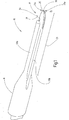
- the preparation instrument 10 has an electrode assembly 12 (see in particular Figures 3 and 4th ) with an electrode 13 and an electrode shaft 14, the electrode 13 being held in the electrode shaft 14.
- the proximal end of the electrode shaft 14 can be detachably inserted in a handle (not shown) of the instrument 10.
- the electrode assembly 12 can be rotatably mounted in the handle to adjust the rotational orientation of the electrode assembly 12 about the longitudinal axis of the electrode shaft.
- the electrode 13 is electrically connected to a high-frequency generator (not shown) via the electrode shaft 14.
- the electrode 13 is surrounded by an insulating body 16 which partially insulates the electrode 13.
- the insulating body 16 covers the insulated sections of the electrode 13 in order to prevent the tissue from being subjected to surgically effective - in particular cutting - or damaging electrical power across the surface of the insulated sections.
- the insulating body 16 preferably covers surface sections of the electrode 13 over a large area or preferably nestles flat against the surface sections to isolate them.
- the insulating body 16 preferably surrounds at least the end of the electrode shaft 14 and extends from there to the working tip 17 of the instrument 10, where the insulating body 16 leaves an edge region 20 of the electrode 13 free.
- the preparation instrument 10 has an end section 21 which extends from the electrode shaft 14 to the distal end of the preparation instrument 10.
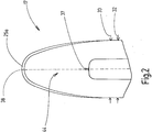
- the electrode 13 has a spatula shape with an upper side 22a and an underside 22b pointing in the opposite direction.
- the upper side 22a and the lower side 22b are connected to each other with a side surface 23a, b and distally to an end surface 24 which adjoins the side surfaces 23a, b.
- the side surfaces 23a, b and the end surface 24 form an edge surface of the electrode 13.
- the end face 24 is preferably completely or at least partially non-insulated.
- the side surfaces 23a, b are preferably insulated up to the end surface 24.
- the electrode 13 preferably looks out of the insulating body 16 distally.
- the electrode 13 preferably points out of the insulating body 16 adjacent to the end face 24.
- the electrode 13 on the side faces 23a, b and / or on the end face 24 is preferably free of recesses open to the side faces 23a, b or the end face 24, which e.g. could form a hook shape of the electrode 13.
- a section 25a of the upper side 22a and / or such a section 25b of the lower side 22b adjoining the end face 24 is not particularly preferred in the form of an arc (has the shape of a curved strip) insulated, the section or sections 25a, b surrounding the insulating body 16 in a top view of the upper side 22a and / or lower side 22b.
- the one or more strip-shaped sections 25a, b adjoin the end face 24.
- the one or more strip-shaped sections 25a, b can have a width B of 0.05 millimeters to 2 millimeters, for example.
- the strip-shaped section has a width B of 0.1 mm to 0.15 mm, for example.
- the electrode 13 is preferably surrounded by the insulating body 16 from its proximal end 28 to the exposed strip-shaped section 25a, b.
- a section of the end face 24 adjoins the surface section 29 of the electrode 13 which has been surrounded up to that point and which is continuously exposed around the distal end 38 of the electrode 13 up to the surrounding surface section 29.
- the width of the end section 21 of the preparation instrument 10 is preferably determined by the width 32 of the insulating body 16.
- the electrode 13 preferably terminates with the insulating body 16 or has a smaller width 33 than the insulating body 16.
- a channel 35 runs along the electrode 13 within the insulating body 16, in the wall that surrounds the electrode 13.
- the channel 35 and the electrode 13 preferably extend side by side with (as shown) or without a distance between the channel 35 and the electrode 13.
- the channel 35 has an outlet 37 at the distal end 36 of the end section 21.
- the outlet 37 of the channel 35 is preferably set back proximally from the distal end 38 of the electrode 13.
- the output 37 can For example, measured parallel to the electrode 13, be set back between at least 2 millimeters up to and including 10 millimeters, for example between 2 millimeters and up to and including 4 millimeters.
- the channel 35 is arranged in the insulating body 16, according to the illustrated embodiment, adjacent to the upper side 22a or, for example, adjacent to the lower side 22b (not shown) in the insulating body 16.
- a channel or a branch of a channel can also be arranged adjacent to the upper side 22a and adjacent to the lower side 22b (not shown). No channel can be arranged adjacent to the other side, the lower side 22b or the upper side 22a.
- the channel 35 extends from parallel (as in Figure 3 illustrated) or at least in sections concentrically (not shown) to the electrode shaft 14 first along the electrode 13 (in the case of a straight electrode 13 parallel to the electrode 13), a preferably straight end section 39 of the channel 35 being preferably angled relative to the electrode 13, so that the angle ⁇ , which the longitudinal axis of the end section 39 of the channel 35 forms with the longitudinal axis 41 of the electrode 13, opens in the distal direction RD.
- the angle ⁇ is in Figure 5 shown, which illustrates a longitudinal sectional view through the distal end portion of the instrument 10.
- the corresponding cutting plane cuts the paper plane in Figure 2 perpendicular along the in Figure 2 dashed line.
- the distal end section 39 of the channel 35 is preferably angled with an angle ⁇ of greater than 0 ° and with respect to the longitudinal axis 41 of the section of the electrode 13 or the insulating body 16 which is arranged in the flow direction of the fluid from the outlet 37 to the outlet 37 up to 45 °, particularly preferably greater than 5 ° to less than 25 °, for example 15 ⁇ 3 °. If the channel 35 is fed with liquid or aerosol, this exits from the outlet 37 of the channel, for example as a cone, for example as a full cone.
- the cone can, for example, have an opening angle (cone angle) of approximately 20 °.
- the cone can be aligned such that the cone defines the section of the insulating body 16 or the electrode 13 between the outlet 37 of the channel 36 and the distal end 38 of the electrode 13 or the instrument 10 does not touch.
- the fluid cone can be aligned such that the spray cone “jacket” is approximately parallel or tangential to the surface of the section 44 of the instrument 10, which extends from the outlet 37 of the channel 35 to the distal end of the instrument 10.
- the distal end portion 39 of the channel 35 is preferably aligned parallel or lies in a plane which is perpendicular to the top 22a or bottom 22b of the electrode and which is in the longitudinal direction of the electrode 13, the wire-shaped portion or Body 48 or in the longitudinal direction of the section of the electrode 13 or of the insulating body 16 which is arranged in the flow direction of the fluid from the outlet 37 to the outlet 37.
- the azimuth between the distal end section 39 of the channel 35 and the longitudinal direction of the electrode 13 and / or the wire-shaped section or body 48 and / or the longitudinal axis of the section of the electrode 13 or the insulating body 16, which is in the flow direction of the fluid from the outlet 37 after the outlet 37 is preferably 0 °, the azimuth between the vertical projection of the longitudinal axis of the distal end section 39 of the channel 35 onto a plane in which the spatula-shaped electrode 13 lies or can be bent such that it is in this plane and / or in which a section of the insulating body 16 or the electrode 13 lies, which is arranged between the outlet 37 of the channel 35 and the distal end of the insulating body 16 and / or the electrode 13, and the longitudinal direction of the electrode 13 and / or a wire-shaped body 48 or section and / or the longitudinal axis of the section of the electrode 13 b between.
- the distal end portion 39 of the channel 35 is preferably a nozzle portion with a flow cross-section that is smaller than the flow cross-section of the channel portion 40 proximally adjacent to the distal end portion 39.
- the proximally adjacent channel portion 40 is preferably 1 millimeter or less in diameter, e.g. about 0.6 millimeters.
- the distal end portion 21 of the instrument 10 with the insulating body 16 and the electrode 13 is preferably flexible, bendable with the bare hand and preferably remains in the shape desired by the user after the bending.
- the end section 21 of the instrument 10 can consequently be bent in directions, in particular from a straight alignment of the electrode 13 and the insulating body 16, so as to adapt the shape of the end section 21 of the instrument 10 to the surgical task.
- the channel 35 is preferably formed by a cavity left free in the insulating body 16. As shown, the cavity runs next to and preferably at a distance from the space in the insulating body 16 which space is filled by the electrode 13. Accordingly, the insulating body 16 preferably forms the wall delimiting the channel 35. The wall which delimits the channel 35 is preferably formed seamlessly in one piece with the insulating body 16. Alternatively or additionally, the distal end section 39, in particular the nozzle section, of the channel is preferably formed by a cavity left free in the insulating body 16.
- the instrument 10 is preferably set up so that the alignment of the nozzle section 39 with respect to the distal electrode section 38 and / or with respect to the longitudinal axis 41 of the section of the insulating body 16 and / or the section of the electrode 13 is in the flow direction of the fluid through the channel 35 seen after the exit 37 (distal of the exit 37) is arranged, can be retained during bending. This is done by forming the nozzle portion 39 in the area of the distal end portion 21 of the instrument 10, which is included by the user for bending the distal end section 21 and consequently in which no bending moment occurs. As a result, the bend of the distal end portion 21 of the instrument 10 always occurs proximal to the nozzle portion 39.
- the distance between the outlet 37 and / or the nozzle section 39 and the distal end 38 of the electrode can be chosen to be so small that when the end section 21 is bent, the bend of the distal end section 21 of the instrument 10 is always securely formed proximal to the nozzle section 39.
- a wire-shaped body 48 is preferably arranged along the electrode 13.
- the electrode 13 can have an elongated slot or recess, which can for example extend in the longitudinal direction of the electrode from the proximal end 28 of the electrode 13 to the distal end 38 of the electrode 13, the wire-shaped body 48 being arranged in the slot or the recess and can fill the recess - as shown.
- the electrode 13 can have, for example, a wire-shaped section which is arranged centrally in the electrode 13 - in the spatula shape. The wire or wire-shaped section serves to stabilize the distal end section 21 of the instrument 10 after bending in the desired orientation into which the distal end section 21 is brought by bending.
- the wire also serves to stabilize the distal end section 21 in the initial configuration before bending, so that mechanical manipulation of the tissue is possible without increasing the thickness of the end section 21 of the electrode 13.
- the latter would namely lead to a deterioration in the electrical Properties of the RF energy input lead, because with a thicker electrode 13, the precision with which preparation can be carried out is less than with a thinner electrode 13.
- the wire-shaped section or body 48 preferably ends in front of the distal end 38 of the electrode 13, so that a region between the distal end 50 of the wire-shaped body 48 and the distal end 38 of the electrode 13 is free of the wire-shaped section or body 48.
- the electrode 13 itself and / or the wire-shaped body or section 48 preferably do not form or contain a fluid channel.
- the electrode 13, with or without a wire-shaped section can be produced by means of a stamping process, or photochemical etching or laser cutting.
- the insulating body 16 can in particular consist of polymer, in particular plastic, for example of silicone.
- the insulating body 16 is preferably formed by encapsulating - in particular overmolding according to an injection molding process - the electrode 13 and the electrode shaft 14 with insulating body material.
- the channel 35 is preferably created as a cavity in the insulating body 16 by molding by means of a core. It is therefore possible to dispense with arranging one or more capillary tubes or hoses, which would lead to a higher mechanical rigidity, in the insulating body 16, the capillary tubes or hoses enclosing the channel.
- the distal end section 21 of the instrument 10 can be precisely aligned with the electrode 13 and the end section 39 of the channel 35 by bending, without the orientation of the fluid jet leaving the exit 37 of the channel 35 changing with respect to the orientation of the distal end 38 of the electrode 13 during bending.
- the distal end section 39, in particular the nozzle section of the channel 35 can also be formed integrally, that is to say as an empty volume in the insulating body 16. An additional component such as a nozzle tube can thus be dispensed with. This is particularly advantageous for the assembly of embodiments of instruments 10 according to the invention.
- the insulating body 16 is preferably formed around the electrode 13, so that the electrode is enclosed by the insulating body 16.
- no adhesion-promoting layer or any other adhesion promoter is arranged between the insulating body 16 and the electrode 13, for example between a silicone body as the insulating body 16 and the electrode 13.
- the longitudinal section 53a of the insulating body 16, the contains the channel 35, is preferably narrower than the adjacent longitudinal section 53b of the insulating body 16, which contains the electrode 13. This also promotes the exact bendability of the insulating body 16.
- the longitudinal section 53b of the insulating body, which contains the electrode 13, in particular the area between the outlet 37 of the channel 35 and the distal end of the instrument 10 or the electrode 13, preferably also has, as illustrated a spatula shape.
- channel 35 can, as in Figure 3 shown next to the electrode shaft 14. In other embodiments, channel 35 may be concentrically disposed within electrode shaft 14 (not shown). This is particularly advantageous if the rotatability of the distal end portion 21 of the instrument 10 about the longitudinal axis of the electrode shaft 14 is to be created relative to the handle, so that the user can orient the distal end portion 21 of the instrument 10 with respect to the handle as the user wishes , can adjust.
- the contour of the electrode 13 in some embodiments merges from the distal end 38 of the electrode 13 into the sides of the electrode without forming rounded corners oriented towards the front (distal).
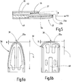
- Figure 6b an example of an embodiment is shown, however, which forms such rounded corners 55a, b.
- the lateral contour of the electrode tip 56 can taper towards the distal end 38 of the electrode (pointed profile, see FIG. Figures 2 , 4th , 6a ), run largely parallel (rectangular profile, see Figure 6b ) or expand (Trapezoidal profile, not shown).
- the free section of the edge surface of the electrode can either be circumferential (over the entire circumference of the spatula-shaped distal end section 21 of the instrument 10) or limited to a distal part of the preferably spatula-shaped distal end section 21 of the instrument 10.
- the width of the electrode defined by the end face preferably abruptly changes to a smaller width at the transition to the side faces and / or at the transition from the exposed area of the upper side 22a and / or the lower face 22b to the non-exposed area Distance between the side surfaces 23a, b is fixed from each other.
- a pointed profile cf. Fig. 2 , 4th , 6a
- the transition from the distal end 38 of the electrode 13 in the longitudinal direction of the electrode 38 can be measured, for example a distance of at most one third of the width 32 of the insulating body 16 in the end section of the instrument 10 and / or the greatest width 33 of the electrode 13 in the distal end section 21 of the instrument 10.
- the length L of the free area of the electrode 13 can be, for example, up to twice the width 32 of the end section 21 of the instrument 10, the length L being measured in the longitudinal direction of the electrode 13.
- the length of the free area can e.g. 4.5 mm or less.
- the channel 35 is preferably connected to a pump or a pressure source in order to supply the channel with gas, liquid and / or aerosol.
- the instrument 10 is manufactured as follows, for example: In an outer shape (not shown), an electrode assembly 12 is provided with an electrode shaft 14 and an electrode 13 and in addition to the electrode 12 and the electrode shaft 14, preferably at a distance from the electrode 12 and / or the electrode shaft 14, an inner elongated shape is provided (elongated core) (not shown) arranged. Insulating body material is injected into the outer shape so that it forms the insulating body 16 around the electrode shaft 14 and the electrode 13. The elongated core ensures that the channel 35 is left free in the insulating body 16.
- the instrument according to the invention works, for example, as follows:
- the instrument 10 according to the invention can be used, for example, in open or laparoscopic or endoscopic surgery.
- the electrode 13 is subjected to HF power and can then be used as a cutting tool to cut tissue.
- the output of a fluid, in particular an aerosol jet, from the outlet 37 of the channel 35 can be activated automatically, for example, by activating the application of RF power to the electrode 13.
- the output of a fluid jet, in particular an aerosol jet can be activated, for example, independently of the activation of the RF power output by the electrode 13.
- an HF spatula (spatula-shaped electrode 13) is combined with a fluid applicator 38 (pump or pressure source and channel), in particular an aerosol applicator (hybrid spatula), by dispensing a fluid, in particular a liquid or aerosol jet, the view of the surgical site is improved and work can be done more precisely and safely.
- tissue can be prepared gently and precisely.
- the instrument 10 supports the user in avoiding inadvertent thermal damage to sensitive (to be prepared) or adjacent structures, since the output of the fluid jet, in particular liquid and aerosol jet, allows the preparation by cleaning or preparing the operating site, so that the contact area between the tissue and the HF electrode 13 is known to the user at any time or can be controlled by him and, moreover, the individual tissue boundaries are always clearly recognizable for the surgeon using the instrument 10.
- the instrument 10 is preferably set up to apply a gas, a liquid or a mixture of both (aerosol) to the tissue (tissue displacement) in order to wash away blood and individual blood, among other things Show tissue structures and their boundaries more clearly.
- the instrument 10 can be set up to introduce liquid or aerosol into the tissue in order to raise a layer of tissue (tissue elevation).
- a fluid in particular a liquid
- the fluid penetrates into the tissue and accumulates in the connective tissue-like border areas between the target structure and the adjacent structures, so that these are pushed apart and an enlarged (safety) distance for manipulation with the instrument 10 arises (mechanical and thermal protection).
- a fluid flow in particular a gas or an aerosol
- displacement effects on the tissue occur as a result of the force of the flowing fluid.
- mechanical properties e.g. the elasticity of the individual tissue structures can be different.
- stiffer structures such as vessels, can be compared to the surrounding softer tissue, e.g. Bold, more clearly delineated.
- the application of an aerosol spray can also cool the operating area and thus provide additional protection against thermal damage caused by HF.
- the aerosol applied with the aid of the channel 35 of the instrument according to the invention can Smoke formation during the HF application can be reduced in order to obtain a significantly improved view of the surgical site.
- the instrument 10 according to the invention consequently meets a need for a preparation instrument that allows precise and gentle exposure / display of sensitive tissue structures.
- the user can bend the end portion 21 of the instrument 10 by hand so that the alignment of the nozzle portion 39 with respect to the distal electrode portion 38 and / or with respect to the longitudinal axis 41 of the portion of the insulating body 16 and / or the longitudinal axis 41 of the section of the electrode 13, which is arranged after the outlet 37 (distal to the outlet 37), viewed in the flow direction of the fluid through the channel 35, is retained.
- Figure 7a and Figure 7b show an example of a further embodiment of the instrument 10 according to the invention.
- This embodiment has a spatula-shaped electrode 13 which can have a longitudinal recess in which a wire-shaped body 48 is arranged, or which has, for example, a central wire-shaped section.
- the channel 35 in the insulating body 16 is adjacent to a narrow side surface 23a of the electrode 13 and not, as in the exemplary embodiments according to FIG Figures 1 to 5 , located adjacent to the wider top 22a of the electrode 13.
- the end section 39 of the channel 35 can - contrary to the illustration - be arranged at an angle ⁇ relative to the longitudinal direction of the distal end section 21 or the electrode 13, so that the angle opens in the distal direction.
- the end section 39 of the channel 35 runs parallel to the longitudinal direction of the electrode 13 or to the longitudinal direction of the distal end section 21.
- the electrode 13 can have a hook recess 60 on one or both side surfaces 23a, b.
- the area 61 of the electrode 13 which is released from the insulating body 16 within the hook recess 62 of the insulating body 16 can be hit by the gas, aerosol or liquid jet in order to clean it.
- a jet from the channel 35 can be applied to tissue which is to be treated in the area within the hook-shaped recess 60, 62 beforehand or simultaneously.
- displacement effects can be generated by applying a gas, aerosol or liquid jet to the tissue which is in contact with the distal end of the electrode 38.
- a suction channel 63 can be arranged in the insulating body 16.
- the insulating body 16 can also form the channel wall of the suction channel 63.
- the electrode 13 projects laterally beyond the insulating body 16, so that the width 64 of the section of the instrument 10 between the output 37 of the Channel 35 and the distal end of the instrument 10 is determined by the electrode 13 and the insulating body 16.
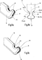
- FIGS. 8a and 8b show examples of embodiments in which the channel 35 is formed in the electrode 13.
- the channel 35 integrated in the electrode 13 can have an outlet 37 at the distal end of the instrument 10.
- the electrode 13 cannot protrude beyond the insulating body 16 either distally or laterally ( Figure 8a ), but terminate, for example, with the insulating body 16, so that only side surface section 63 is uncovered by the insulating body 16. Otherwise, the electrode 13 cannot protrude distally beyond the insulating body 16, but only lateral portions 64 of the upper side 22a and / or the lower side 22b of the electrode 13 can, as illustrated, be uncovered by the insulating body 16.
- the exemplary embodiments shown also differ in that in Figure 8a only one side surface 23a of the instrument 10 has a hook through a recess 60, 62 in the insulating body 16 from the electrode 13 and in Figure 8b both side surfaces 23a, b have a hook.
- the example according to Figure 8c differs from the example according to Figure 8a in particular in that the electrode 13 in the hook recess 62 of the insulating body 16, as well as distally and beyond, laterally protrudes beyond the adjacent contour of the insulating body 16.
- a recess can be present in the insulating body, through which a flat section of the electrode is free for coagulation in order to form a coagulation area.
- a coagulation area can be formed (not shown) by a section of the insulating body having a porosity which is adapted such that the insulating body in this section does not insulate the electrode in order to apply electrical power to the tissue for coagulation of the tissue by the latter Allow section.
- a preparation instrument 10 (hybrid instrument) which has an HF instrument with an electrode 13 which is partially insulated by means of an insulating body 16 and which is combined with a fluid applicator with a channel 35 arranged in the insulating body 16 for application of a fluid to or in tissue .
- the electrode 13 is a spatula electrode which is inserted in the insulating body 16 and does not cover sections 24, 25a, 25b, 63, 64 of the surface of the electrode 13, so that these sections 24, 25a, 25b, 63, 64 may have tissue contact.
- the insulating body 10 preferably forms the channel wall delimiting the channel 35.
- the insulating body 16 and the electrode 13 are flexible in order to adapt the shape of the insulating body 16 and the electrode 13 together to the surgical task.
- Electrode shaft 10th Preparation instrument / instrument 12th Electrode assembly 13 electrode 14 Electrode shaft 16 Insulating body 17th Work tip 20th Edge area of the electrode 21 End section 22a Top 22b bottom 23a, b Side faces 24th Face 25a, b Sections 28 Proximal end of the electrode 29 Surface section 32 Width of the insulator 33 Width of the electrode 35 channel 36 Distal end 37 Exit of the channel 38 Distal end of the electrode 39 End section of the channel / nozzle section 40 Proximal section of the canal 41 Longitudinal axis of the electrode 44 Section of the instrument 48 Wire-shaped body 50 Distal end of the wire-shaped body / section 52 Recess 53a, b Longitudinal sections 55a, b Corners 56 Electrode tip 60 Hook recess 61 Area 62 Hook recess 63 Side surface section 64 section ⁇ angle RD Distal direction L length B width
Landscapes
- Health & Medical Sciences (AREA)
- Surgery (AREA)
- Life Sciences & Earth Sciences (AREA)
- Engineering & Computer Science (AREA)
- Biomedical Technology (AREA)
- Public Health (AREA)
- Nuclear Medicine, Radiotherapy & Molecular Imaging (AREA)
- Veterinary Medicine (AREA)
- General Health & Medical Sciences (AREA)
- Heart & Thoracic Surgery (AREA)
- Medical Informatics (AREA)
- Molecular Biology (AREA)
- Animal Behavior & Ethology (AREA)
- Physics & Mathematics (AREA)
- Otolaryngology (AREA)
- Plasma & Fusion (AREA)
- Surgical Instruments (AREA)
- Electrostatic Spraying Apparatus (AREA)
Abstract
Description
- Die Erfindung betrifft ein HF-chirurgisches Präparationsinstrument.
- Neben dem rein mechanischen Präparieren mit Schere und Pinzette sind die diathermischen Verfahren (Hochfrequenz(HF)-chirurgische Verfahren) heute das Mittel der Wahl. Derzeit werden zur Präparation von Gewebestrukturen nicht-isolierte Spatel- oder Hakenelektroden verwendet. Teilweise isolierte Elektroden hingegen finden insbesondere dann ihre Anwendung, wenn eine thermische Schädigung der freizustellenden oder angrenzenden Strukturen möglichst gering sein soll. Bei bekannten Präparationsinstrumenten kann das präzise und sichere Arbeiten insbesondere durch eingeschränkte Sicht auf den OP-Situs, zum Beispiel in Folge von Sickerblutungen, karbonisiertem Blut und Gewebe sowie Überdeckungen der Instrumentenspitze (des aktiven Bereichs) durch "fließendes" Gewebe erschwert sein.
- Aus
US 2006/0 111 709 A1 ist ein elektrochirurgisches Instrument bekannt, welches eine Hakenelektrode aufweist, wobei Kühlfluid von einem Reservoir durch den Instrumentenkörper, an die Elektrodenspitze, durch eine Öffnung in der Elektrode und von dort in einen Rückführungskanal zum Reservoir geleitet werden kann. Dadurch ist die Elektrode kühlbar. -
WO 95/19 739 A -
WO 2016/0731 64 A1 zeigt ein elektrochirurgisches Instrument mit einer nicht isolierten Elektrode, die einen Kanal umschließt, durch welchen Gas aus einer Öffnung am Ende der Elektrode ausgestoßen wird, um Sauerstoff von dem Ende der Elektrode zu verdrängen. - Auf der Webseite http://mmcts.org/tutorial/830#additionalinfo wird ein Instrument offenbart, welches aus einem elektrochirurgischen Instrument und einem Instrument zur Ausbringung eines CO2- und Kochsalzlösung-Gemisches zusammengesetzt ist, wobei das elektrochirurgische Instrument und das weitere Instrument mit Fäden verbunden sind.
- Ausgehend von diesem Stand der Technik ist es Aufgabe der vorliegenden Erfindung, ein verbessertes Instrument bereitzustellen.
- Diese Aufgabe wird mit einem HF-chirurgischen Präparationsinstrument nach Anspruch 1 sowie einer Vorrichtung nach Anspruch 15 gelöst:
- Das HF-chirurgische Präparationsinstrument (im Folgenden auch Präparationsinstrument oder Instrument genannt) weist eine Elektrode zum Beaufschlagen von Gewebe mit HF-Leistung auf, wobei Oberflächenabschnitte der Elektrode mittels eines Isolierkörpers nach außen elektrisch und thermisch isoliert sind. Innerhalb des Isolierkörpers ist ein Kanal angeordnet, der zum Ausbringen eines Fluides, wie eines Gases, einer Flüssigkeit und/oder eines Aerosols, auf oder in das Gewebe oder zwischen Gewebestrukturen eingerichtet ist. Der Kanal ist an eine Fluidquelle, beispielsweise Gas-, Flüssigkeits- und/oder Aerosolquelle, anschließbar, insbesondere angeschlossen.
- Das Instrument ist vorzugsweise ein monopolares HF-Instrument. Der HF-Generator, welcher das Instrument speist, ist mit einer gesonderten Neutralelektrode verbunden, welche den Patienten großflächig elektrisch kontaktiert.
- Mit dem HF-chirurgischen Präparationsinstrument kann Gas, Flüssigkeit und/oder Aerosol in oder neben einen Einwirkungsbereich der HF-Leistung gebracht werden. Das Präparationsinstrument bildet entsprechend einen Fluidapplikator.
- Unter einem Aerosol wird im Sinne dieser Anmeldung ein Gemisch aus in einem Gas und einer Flüssigkeit, insbesondere aus in einem Gas schwebenden Flüssigkeitströpfchen, verstanden.
- Mit dem erfindungsgemäßen Instrument lässt sich Gewebe schonend und präzise präparieren. Unter Präparation wird hier die Freilegung und Darstellung von vulnerablen anatomischen Strukturen, wie z.B. Nerven oder Gefäßen durch stumpfes Auseinanderschieben/Abdrängen und/oder scharfes Trennen verstanden. Bei der HF-chirurgischen Präparation werden z.B. mit Hilfe eines HF-Spatels bestimmte Gewebestrukturen wie Gefäße, Nerven oder Organe zumindest teilweise aus dem Gewebeverbund herausgelöst. Bei diesem Schritt ist es entscheidend, dass es zu keiner unbeabsichtigten thermischen Schädigung sensibler (zu präparierender) oder angrenzender Strukturen kommt. Das erfindungsgemäße Instrument gewährleistet, dass eine Kontaktfläche zwischen dem Gewebe und der HF-Elektrode zu jedem Zeitpunkt bekannt bzw. kontrollierbar ist. Durch Ab- oder Verdrängen von Gewebe, Gewebestrukturen, Geweberesten, Körperflüssigkeiten oder sonstigen Flüssigkeiten oder Nebeln mittels der Gas-, Flüssigkeits-, und/oder Aerosolapplikatorfunktion des erfindungsgemäßen Instruments kann der Chirurg die einzelnen Gewebegrenzen stets deutlich erkennbar machen.
- Der Kanal verläuft bevorzugt neben der Elektrode, mit oder ohne Abstand zu der Elektrode. Alternativ kann die Elektrode den Kanal enthalten. Bevorzugt jedoch begrenzt der Isolierkörper den Kanal. Dies bedeutet, dass der Isolierkörper zumindest abschnittsweise die Kanalwand bildet. In dem Abschnitt kann beispielsweise auf ein Röhrchen in dem Isolierkörper verzichtet werden, wobei das Röhrchen den Kanalabschnitt enthält. Der Kanal verläuft vorzugsweise innerhalb der Wandstärke des Isolierkörpers. Die Elektrode verläuft bevorzugt mit Abstand zu dem Kanal entlang des Kanals. Die Elektrode ist bevorzugt nicht in dem Kanal angeordnet und reicht bevorzugt nicht in den Kanal hinein, so dass der Kanal die Elektrode in einer Querschnittsebene durch den Kanal gesehen vorzugsweise nicht umgibt.
- Bevorzugt weist der Kanal einen Düsenabschnitt als Endabschnitt auf, in welchem sich der Querschnitt, insbesondere Durchmesser des Kanals, verjüngt. Der Düsenabschnitt wird vorzugsweise von dem Isolierkörper begrenzt. Dies bedeutet, dass der Isolierkörper die Wand des Düsenabschnitts des Kanals bildet.
- Der distale Endabschnitt (Instrumentenspitze), insbesondere die Elektrode und der Isolierkörper, ist vorzugsweise biegbar, um die Form des Isolierkörpers und der Elektrode an die Behandlungsaufgabe anzupassen. Wenn die äußere Kraft zum Verbiegen weggenommen wird, bleibt die gewünschte Form des Endabschnitts des Isolierkörpers vorzugsweise erhalten. Die Ausrichtung der Düse des Kanals relativ zu der Elektrodenspitze bleibt vorzugsweise erhalten. Vorzugsweise ist der Endabschnitt mit der Hand biegbar. Wenn der Endabschnitt in die gewünschte Form biegbar ist, fördert dies eine präzise und gewebeschonende Präparation, wie zum Beispiel bei der Gefäßentnahme.
- Durch die Isolation kann die elektrische Kontaktfläche zwischen der Elektrode und dem Gewebe auf einen definierten und eng begrenzten Bereich festgelegt werden. Dadurch sinkt zum einen die in das Gewebe eingebrachte Energie. Zum anderen werden durch den begrenzten Wirkbereich der Lateralschaden sowie das Risiko einer unbeabsichtigten thermischen Beanspruchung des umliegenden Gewebes minimiert.
- Wenn der Isolierkörper den Kanal begrenzt, insbesondere wenn der Isolierkörper den Endabschnitt des Kanals begrenzt, der an die Öffnung des Kanals zum Auslass des Aerosols oder der Flüssigkeit in das Einwirkgebiet des Instruments gestattet, führt dies dazu, dass bei Verbiegung des Instruments die Ausrichtung (Winkel) des Endabschnitts des Kanals relativ zu der Ausrichtung des distalen Endabschnitts der Elektrode erhalten bleibt.
- Die Elektrode ist bevorzugt nicht in einem Kanal angeordnet, der zum Führen eines Fluidstroms bestimmt wäre. Die Elektrode kann in einer Ausnehmung in dem Isolierkörper angeordnet sein. Die Elektrode kann die Ausnehmung vollständig ausfüllen oder zumindest die Öffnung in die Ausnehmung verschließen.
- In bevorzugten Ausführungsformen weist die Elektrode eine Spatelform auf. Dies bedeutet, dass die Elektrode zumindest einen spatelförmigen distalen Endabschnitt aufweist. Das Instrument bildet mit einer spalteförmigen Elektrode vorzugsweise einen HF-Spatel. In bevorzugten Ausführungsformen weist die Elektrode einen drahtförmigen Abschnitt auf, der sich vorzugsweise entlang der Längserstreckung der Elektrode erstreckt. Alternativ kann die Elektrode beispielsweise einen länglichen Schlitz oder Ausnehmung aufweisen, die sich beispielsweise vom proximalen Ende der Elektrode bis zum Endabschnitt der Elektrode erstrecken kann, wobei in dem Schlitz oder Ausnehmung ein drahtförmiger Körper, vorzugsweise Metallkörper, angeordnet ist. Der drahtförmige Körper ist vorzugsweise mit der Elektrode verbunden, beispielsweise mit dem Elektrodenblech verschweißt. Der drahtförmige Körper dient nicht unbedingt der Stromführung, sondern kann auch zu rein mechanischen Zwecken angeordnet sein, um das Verbiegen des Endabschnitts des Instruments und das Halten des Endabschnittes in der gewünschten verbogenen Form zu erlauben. Der drahtförmige Körper kann demnach der Leitung elektrischer Leistung in die Elektrode und/oder der mechanischen Stabilisierung der Elektrode dienen. Um mit dem Präparationsinstrument besonders präzise und isoliert präparieren zu können, ist eine dünne Elektrode wünschenswert. Mit abnehmender Dicke der Elektrode sinkt jedoch die mechanische Steifigkeit der Elektrode. Dies kann bei Bedarf durch den drahtförmigen Körper oder Abschnitt kompensiert werden. Darüber hinaus kann durch den drahtförmigen Körper oder Abschnitt der Wärmeabtransport von der Spitze des Präparationsinstruments durch den Endabschnitt des Präparationsinstruments verbessert werden.
- Wenn, wie in Ausführungsbeispielen des erfindungsgemäßen Instruments, ein HF-Spatel mit einem Fluidapplikator kombiniert ist (Hybridspatel) kann dadurch die thermische Schädigung der Strukturen weitgehend reduziert und die Sicht auf den OP-Situs verbessert werden. Das Instrument erlaubt es, ein Fluid, beispielsweise ein Gas, eine Flüssigkeit oder eine Mischung aus beiden, zur Gewebeverdrängung auf das Gewebe zu applizieren bzw. in das Gewebe zur Gewebeelevation einzutragen. Dadurch können einzelne Gewebestrukturen bzw. deren Grenzen deutlicher dargestellt werden. Außerdem können durch die Ausgabe von Fluid Körperflüssigkeiten, wie unter anderem Blut, Gewebereste, Nebel, Rauch und dgl. weggespült bzw. verdrängt werden.
- Bei der Applikation eines Fluids (insbesondere einer Flüssigkeit) mit hoher Leistungsdichte, dringt es in das Gewebe ein und reichert sich in den bindegewebsartigen Grenzbereichen zwischen der Zielstruktur und den angrenzenden Strukturen an, so dass diese auseinandergedrängt werden und ein vergrößerter (Sicherheits-)Abstand für die Manipulation mit dem Instrument entsteht (mechanischer und thermischer Schutz).
- Wird hingegen ein Fluidstrom (insbesondere ein Gas) mit relativ niedriger Intensität in einem gewissen Abstand auf das Gewebe gerichtet, so kommt es infolge der Kraftwirkung des strömenden Fluids zu Verdrängungseffekten (Deformation) am Gewebe. Diese können aufgrund unterschiedlicher mechanischer Eigenschaften, z.B. der Elastizität der einzelnen Gewebestrukturen unterschiedlich stark ausgeprägt sein. Dadurch können zum Beispiel steifere Strukturen wie Gefäße gegenüber dem umgebenden weicheren Gewebe, wie beispielsweise Fett, deutlicher abgegrenzt werden.
- Durch die Applikation eines Aerosol-Sprays kann außerdem eine Kühlung des Operationsbereichs und somit ein zusätzlicher Schutz vor thermischer Schädigung durch HF-Einwirkung realisiert werden. Da ein Aerosol die Rauchbildung während der HF-Anwendung reduziert, kann die Sicht auf den OP-Situs deutlich verbessert werden.
- Um den Anwender bei der Vermeidung einer schadhaften Wirkung des Fluids, insbesondere Aerosols, zu unterstützen und/oder um insbesondere Gas- oder Aerosoleintrag in das Gewebe, z.B. ein Blutgefäß, zu verhindern, kann der Ausgang des Kanals, insbesondere der Ausgang der Düse, vorzugsweise proximal von dem distalen Ende der Elektrode zurückversetzt sein. Insbesondere wird so ein Aufsetzen des Ausgangs des Kanals auf das Gewebe verhindert. In bevorzugten Ausführungsformen ist das distale Ende des Kanals, an welchem der Ausgang angeordnet ist, von dem distalen Ende der Elektrode von einschließlich 2 mm bis einschließlich 10 mm zurückversetzt. In Ausführungsformen kann das distale Ende des Kanals bzw. der Ausgang des Kanals von dem distalen Ende der Elektrode beispielsweise zwischen 2 und 4 Millimeter in proximaler Richtung zurückversetzt sein.
- Die spatelförmige Elektrode weist eine Oberseite und eine Unterseite auf, welche an den Rändern der Elektrode über je eine Seitenfläche verbunden sind. Der distale Endabschnitt des Kanals liegt bevorzugt in einer Ebene, welche von der Längsachse der Elektrode oder der Längsachse des drahtförmigen Abschnitts oder Körpers oder der Längsachse des Abschnitts der Elektrode bzw. des Isolierkörpers, der in Strömungsrichtung des Fluids aus dem Ausgang des Kanals nach dem Ausgang des Kanals angeordnet ist, und einer Flächennormalen der Oberseite oder der Unterseite der Elektrode aufgespannt wird. Der Ausrichtungswinkel (Azimuth) zwischen dem distalen Endabschnitt des Kanals und der Längserstreckungsrichtung der Elektrode und/oder eines drahtförmigen Körpers und/oder der Längsachse des Abschnitts der Elektrode bzw. des Isolierkörpers, der in Strömungsrichtung des Fluids aus dem Ausgang des Kanals nach dem Ausgang des Kanals angeordnet ist, ist entsprechend besonders bevorzugt 0°. Alternativ kann der Azimuth 0°± 10° oder 0°± 5° oder aus einem anderen Winkelbereich sein.. Der Azimuth wird bevorzugt in einer Ebene gemessen in welcher die spatelförmige Elektrode liegt oder derart gebogen werden kann, dass sie in dieser Ebene liegt, und/oder in welcher ein Abschnitt des Isolierkörpers oder der Elektrode liegt, welcher zwischen dem Ausgang des Kanals und dem distalen Ende des Isolierkörpers und/oder der Elektrode angeordnet ist.
- Die Elektrode weist in Ausführungsformen des Instruments keine Öffnung auf, durch welche Gas, Flüssigkeit und/oder Aerosol hindurchgeleitet wird. Die Elektrode weist insbesondere vorzugsweise keinen in der Elektrode verlaufenden Kanal auf, der im Betrieb des Instruments ein Gas, ein Aerosol oder eine Flüssigkeit leiten würde.
- Die Elektrode des erfindungsgemäßen Instruments schaut distal bevorzugt aus dem Isolierkörper heraus. Auf diese Weise geht von der Elektrode auch seitlich über den nicht isolierten Abschnitt eine Übertragung von HF-Leistung in das Gewebe aus.
- Der Bereich der Oberseite und/oder der Bereich der Unterseite der Elektrode, der von dem Isolierkörper vorzugsweise freigestellt ist, ist vorzugsweise bogenförmig oder umgibt den Isolierkörper (in der Draufsicht) bogenförmig. Der freigestellte Bereich kann neben einem Abschnitt des Isolierkörpers enden, der zwischen dem Ausgang des Kanals und dem distalen Ende des Instruments angeordnet ist. Der freigestellte Bereich endet damit aus Sicht des Anwenders distal des Ausgangs. Alternativ kann der freigestellte Bereich neben einem Abschnitt des Isolierkörpers enden, der den Kanal enthält. Der freigestellte Bereich endet damit proximal des Ausgangs. Wenn der freigestellte Bereich proximal des Ausgangs des Kanals endet, erstreckt sich der freigestellte Bereich der Elektrode in Richtung proximal neben dem Ausgang des Kanals über den Ausgang des Kanals hinaus.
- Die Freistellung durch den Isolierkörper kann auf solche Bereiche der Elektrode beschränkt sein, deren nächster Randflächenabschnitt eine Orientierung mit einer Komponente in distaler Richtung aufweist. Die Freistellung durch den Isolierkörper kann insbesondere auf solche Bereiche der Elektrode beschränkt sein, deren nächster Randflächenabschnitt ein Abschnitt der Stirnfläche der Elektrode ist.
- Der Isolierkörper kann ein oder mehrteilig sein. Teile des Isolierkörpers können miteinander verbunden sein oder die Teile sind separat, voneinander beabstandet. Bevorzugt ist der Isolierkörper nahtlos einstückig ausgebildet. Die Elektrode kann in einer Ausnehmung in dem Isolierkörper angeordnet sein oder die Elektrode kann beispielsweise zwischen zwei nicht verbundenen Hälften des Isolierkörpers angeordnet sein, welche Abschnitte der Oberseite und der Unterseite der Elektrode flächig bedecken können.
- Der Isolierkörper besteht vorzugsweise aus einem Polymer, insbesondere Kunststoff, beispielsweise Silikon. Bevorzugt ist der Isolierkörper flexibel um ein Verbiegen des distalen Endabschnitts des Instruments zuzulassen. Der Isolierkörper bedeckt Oberflächenabschnitte der Elektrode, um zu verhindern, dass das Gewebe von den bedeckten Oberflächenabschnitten aus mit chirurgisch wirksamer oder schädigender elektrischer Leistung beaufschlagt wird. Beispielsweise kann so ein unerwünschtes Austrocknen von Gewebeabschnitten verhindert werden. Von von dem Isolierkörper unbedeckten Oberflächenabschnitten aus kann das Gewebe durch die Oberflächenabschnitte mit chirurgisch wirksamer elektrischer Leistung beaufschlagt werden.
- In bevorzugten Ausführungsformen wird der Isolierkörper durch Umspritzen der Elektrode hergestellt. Vorzugsweise wird dazu bei der Herstellung des erfindungsgemäßen Instruments in einer äußeren Form neben der Elektrode und/oder neben dem Elektrodenschaft, bevorzugt mit Abstand entlang der Elektrode und/oder dem Elektrodenschaft, ein Kern angeordnet, der den Kanal beim Umspritzen der Elektrode zumindest abschnittsweise freilässt oder bildet. Der Kern wird danach entfernt. Zurück bleibt der Kanal innerhalb der Wandstärke (Wanddicke) des die Elektrode umgebenden Isolierkörpers.
- Die Elektrode weist vorzugsweise Ausnehmungen, insbesondere Löcher, zum Befestigen des Isolierkörpers an der Elektrode auf. Wenn der Isolierkörper durch Gießen, insbesondere Spritzgießen hergestellt wird, kann das Gussmaterial durch die Löcher treten und in den Löchern fest werden, so dass ein Formschluss zwischen dem Isolierkörper und der Elektrode hergestellt wird.
- Die Elektrode ist vorzugsweise in einem Elektrodenschaft gefasst, wobei der Isolierkörper zumindest einen distalen Endabschnitt des Elektrodenschafts umgeben kann, um diesen elektrisch zu isolieren. Der drahtförmige Körper kann in oder an dem Elektrodenschaft befestigt sein, insbesondere in dem Elektrodenschaft stecken.
- Der Kanal verläuft neben dem Elektrodenschaft oder beispielsweise abschnittsweise konzentrisch mit dem Elektrodenschaft.
- Das Instrument kann einen Handgriff aufweisen, in welchem der Elektrodenschaft drehbar gelagert ist und der Anwender die Winkelstellung der Elektrode bezüglich des Handgriffs anpassen kann. Wenn der Kanal konzentrisch mit dem Elektrodenschaft verläuft, kann der Kanal zentral mit einer Gas-, Flüssigkeits- und/oder Aerosolleitung zur Gas-, Flüssigkeits- und/oder Aerosolquelle verbunden sein.
- Es wird zudem eine Vorrichtung angegeben, welche ein erfindungsgemäßes Instrument und eine Gas-, Fluid- und/oder Aerosolquelle aufweist, wobei der Kanal des Instruments mit der Gas-, Fluid- und/oder Aerosolquelle verbunden ist, um den Kanal mit Gas, Flüssigkeit und/oder Aerosol zu speisen.
- Weitere bevorzugte Merkmale und Ausführungsformen des erfindungsgemäßen Instruments und der erfindungsgemäßen Vorrichtung ergeben sich aus nachfolgender Beschreibung, den Figuren sowie den Unteransprüchen. Die Figuren zeigen:
-
Figur 1 - ein erfindungsgemäßes Instrument gemäß einer beispielhaften Ausführungsform in einer perspektivischen Ansicht, -
Figur 2 - eine Draufsicht auf das distale Ende des Instruments gemäßFigur 1 , -
Figur 3 - das Instrument gemäßFigur 1 in perspektivischer Ansicht mit durch gestrichelte Linien angedeuteter Lage der Elektrode und des Kanals, -
Figur 4 - eine beispielhafte Elektrodenbaugruppe mit Elektrodenschaft und Elektrode des Instruments gemäßFigur 1 , -
Figur 5 - eine ausschnittsweise Längsschnittansicht des Instruments gemäßFigur 1 entlang der Längsachse der Elektrode, -
Figur 6a, 6b - Draufsichten auf Ausführungsbeispiele distaler Spatelabschnitte, -
Figur 7a - eine perspektivische Ansicht auf den distalen Endabschnitt eines Beispiels einer weiteren Ausführungsform des erfindungsgemäßen Instruments, -
Figur 7b - ein Längsschnittdarstellung des Beispiels gemäßFigur 7a , -
Figur 8a - eine perspektivische Darstellung eines Beispiels einer dritten Ausführungsform des erfindungsgemäßen Instruments, -
Figur 8b - eine Draufsicht auf eine Oberseite eines weiteren Beispiels gemäß einer dritten Ausführungsform des erfindungsgemäßen Instruments, -
Figur 8c - eine perspektivische Darstellung eines noch weiteren Beispiels gemäß der dritten Ausführungsform des erfindungsgemäßen Instruments. - Einzelheiten eines Beispiels eines bevorzugten Aufbaus eines erfindungsgemäßen Präparationsinstruments 10 gemäß einer Ausführungsform sind in den
Figuren 1 bis 5 veranschaulicht. Das Präperationsinstrument 10 weist eine Elektrodenbaugruppe 12 (s. insbesondereFiguren 3 und4 ) mit einer Elektrode 13 und einem Elektrodenschaft 14 auf, wobei die Elektrode 13 in dem Elektrodenschaft 14 gehalten ist. Das proximale Ende des Elektrodenschaftes 14 kann lösbar in einem Handgriff (nicht gezeigt) des Instruments 10 stecken. Die Elektrodenbaugruppe 12 kann in dem Handgriff drehbar gelagert sein, um die Drehorientierung der Elektrodenbaugruppe 12 um die Längsachse des Elektrodenschaftes anzupassen. Die Elektrode 13 ist über den Elektrodenschaft 14 elektrisch mit einem Hochfrequenz-Generator (nicht gezeigt) verbunden. Die Elektrode 13 ist von einem Isolierkörper 16 umgeben, welcher die Elektrode 13 teilweise isoliert. Dies bedeutet, dass der Isolierkörper 16 die isolierten Abschnitten der Elektrode 13 bedeckt, um zu verhindern, dass das Gewebe quer durch die Oberfläche der isolierten Abschnitte mit chirurgisch wirksamer - insbesondere schneidender - oder schädigender elektrischer Leistung beaufschlagt wird. Der Isolierkörper 16 bedeckt Oberflächenabschnitte der Elektrode 13 vorzugsweise flächig oder schmiegt sich bevorzugt flächig an die Oberflächenabschnitte an, um diese zu isolieren. Der Isolierkörper 16 umgibt bevorzugt zumindest das Ende des Elektrodenschaftes 14 und erstreckt sich von dort bis zur Arbeitsspitze 17 des Instruments 10, wo der Isolierkörper 16 einen Randbereich 20 der Elektrode 13 freilässt. Das Präparationsinstrument 10 weist einen Endabschnitt 21 auf, der sich von dem Elektrodenschaft 14 bis zu dem distalen Ende des Präparationsinstruments 10 erstreckt. - Die Elektrode 13 weist eine Spatelform mit einer Oberseite 22a und einer in entgegengesetzte Richtung weisenden Unterseite 22b auf. Die Oberseite 22a und die Unterseite 22b sind miteinander mit je einer Seitenfläche 23a,b und distal mit einer Stirnfläche 24 verbunden, die an die Seitenflächen 23a,b angrenzt. Die Seitenflächen 23a, b und die Stirnfläche 24 bilden eine Randfläche der Elektrode 13.
- Die Stirnfläche 24 ist bevorzugt vollständig oder zumindest teilweise nicht-isoliert. Die Seitenflächen 23a,b sind bis zu der Stirnfläche 24 bevorzugt isoliert. Die Elektrode 13 schaut distal vorzugsweise aus dem Isolierkörper 16 hervor. Bevorzugt zeigt die Elektrode 13 angrenzend an die Stirnfläche 24 aus dem Isolierkörper 16 heraus.
- Die Elektrode 13 ist an den Seitenflächen 23a,b und/oder an der Stirnfläche 24 vorzugsweise frei von zu den Seitenflächen 23a,b oder der Stirnfläche 24 offenen Ausnehmungen, welche z.B. eine Hakenform der Elektrode 13 bilden könnten.
- Besonders bevorzugt ist ein bogenförmiger (weißt die Form eines gekrümmten Streifens auf), an die Stirnfläche 24 angrenzender Abschnitt 25a der Oberseite 22a und/oder ein solcher Abschnitt 25b der Unterseite 22b nicht isoliert, wobei der oder die Abschnitte 25a,b in der Draufsicht auf Oberseite 22a und/oder Unterseite 22b, den Isolierkörper 16 umgeben. Der oder die streifenförmigen Abschnitte 25a,b grenzen an die Stirnfläche 24 an. Der oder die streifenförmigen Abschnitte 25a,b können beispielsweise eine Breite B von 0,05 Millimeter bis 2 Millimeter aufweisen. In den Ausführungsbeispielen gemäß
Figur 6a und 6b weist der streifenförmige Abschnitt beispielsweise eine Breite B von 0,1 mm bis 0,15 mm auf. - Bevorzugt ist die Elektrode 13 von ihrem proximalen Ende 28 bis zu dem freigestellten streifenförmigen Abschnitt 25a,b geschlossen von dem Isolierkörper 16 umgeben. An den bis dorthin umgebenen Oberflächenabschnitt 29 der Elektrode 13 schließt ein Abschnitt der Stirnfläche 24 an, der um das distale Ende 38 der Elektrode 13 herum bis zurück zu dem umgebenen Oberflächenabschnitt 29 durchgängig freigestellt ist.
- Die Breite des Endabschnitts 21 des Präparationsinstruments 10 wird vorzugsweise von der Breite 32 des Isolierkörpers 16 bestimmt. Die Elektrode 13 schließt bevorzugt mit dem Isolierkörper 16 ab oder weist eine geringere Breite 33 auf als der Isolierkörper 16.
- Innerhalb des Isolierkörpers 16, in der Wand, welche die Elektrode 13 umgibt, verläuft ein Kanal 35 entlang der Elektrode 13. Der Kanal 35 und die Elektrode 13 erstrecken sich bevorzugt nebeneinander mit (wie dargestellt) oder ohne Abstand zwischen Kanal 35 und Elektrode 13. An dem distalen Ende 36 des Endabschnitts 21 weist der Kanal 35 einen Ausgang 37 auf. Der Ausgang 37 des Kanals 35 ist von dem distalen Ende 38 der Elektrode 13 vorzugsweise proximal zurückversetzt angeordnet. Der Ausgang 37 kann beispielsweise, parallel zur Elektrode 13 gemessen, zwischen wenigstens 2 Millimeter bis einschließlich 10 Millimeter zurückversetzt sein, beispielsweise zwischen einschließlich 2 Millimeter bis einschließlich 4 Millimeter.
- Der Kanal 35 ist in dem Isolierkörper 16 gemäß dargestellter Ausführungsform benachbart zu der Oberseite 22a oder beispielsweise benachbart der Unterseite 22b (nicht dargestellt) in dem Isolierkörper 16 angeordnet. Es kann auch je ein Kanal oder je ein Zweig eines Kanals benachbart zu der Oberseite 22a und benachbart zu der Unterseite 22b angeordnet sein (nicht dargestellt). Benachbart zu der anderen Seite, der Unterseite 22b oder der Oberseite 22a, kann kein Kanal angeordnet sein. Der Kanal 35 erstreckt sich von parallel (wie in
Figur 3 veranschaulicht) oder zumindest abschnittsweise konzentrisch (nicht gezeigt) zu dem Elektrodenschaft 14 zunächst entlang der Elektrode 13 (bei gerader Elektrode 13 parallel zur Elektrode 13), wobei ein, bevorzugt gerader, Endabschnitt 39 des Kanals 35 relativ zu der Elektrode 13 bevorzugt angewinkelt ist, so dass sich der Winkel α, den die Längsachse des Endabschnitts 39 des Kanals 35 mit der Längsachse 41 der Elektrode 13 einschließt, in distale Richtung RD öffnet. Der Winkel α ist inFigur 5 dargestellt, welche eine Längsschnittansicht durch den distalen Endabschnitt des Instruments 10 veranschaulicht. Die entsprechende Schnittebene schneidet die Papierebene inFigur 2 senkrecht entlang der inFigur 2 gestrichelt eingezeichneten Schnittlinie. Der distale Endabschnitt 39 des Kanals 35 ist bezüglich der Längsachse 41 des Abschnitts der Elektrode 13 bzw. des Isolierkörpers 16, der in Strömungsrichtung des Fluids aus dem Ausgang 37 nach dem Ausgang 37 angeordnet ist, vorzugsweise angewinkelt mit einem Winkel α von größer 0° und bis 45°, besonders bevorzugt größer 5° bis kleiner 25°, beispielsweise 15±3°. Wenn der Kanal 35 mit Flüssigkeit oder Aerosol gespeist wird, tritt dieses aus dem Ausgang 37 des Kanals beispielsweise als Kegel, beispielsweise als Vollkegel aus. Der Kegel kann beispielsweise einen Öffnungswinkel (Kegelwinkel) von etwa 20° aufweisen. Auf Grund der Ausrichtung des distalen Endabschnitts 39 des Kanals 35 kann der Kegel derart ausgerichtet sein, dass der Kegel den Abschnitt des Isolierkörpers 16 bzw. der Elektrode 13 zwischen dem Ausgang 37 des Kanals 36 und dem distalen Ende 38 der Elektrode 13 bzw. des Instruments 10 nicht streift. In Ausführungsbeispielen kann der Fluidkegel derart ausgerichtet sein, dass der Sprühkegel"mantel" etwa parallel oder tangential zur Oberfläche des Abschnitts 44 des Instruments 10 ist, der sich von dem Ausgang 37 des Kanals 35 bis zum distalen Ende des Instruments 10 erstreckt. Würde der Strahlkegel den Abschnitt 44 hingegen treffen, kann dies zu einer erheblichen, unkontrollierten Tropfenbildung (Ansammlung von Flüssigkeit an der Elektrodenspitze) führen und könnte zum einen die elektrischen Eigenschaften des Spatels negativ beeinflussen, denn durch die Ansammlung von leitfähiger Flüssigkeit an der Spitze des Instruments kann die effektive Kontaktfläche der Elektrode vergrößert sein und die Ansammlung kann somit dem Ziel einer präzisen (isolierten) Präparation entgegenwirken, und zum anderen die Sicht auf das Operationsfeld einschränken. - Wie in den
Figuren 3 und insbesondere 5 gezeigt, ist der distale Endabschnitt 39 des Kanals 35 vorzugsweise parallel entlang einer Ebene ausgerichtet oder liegt in der Ebene, welche senkrecht zu der Oberseite 22a oder Unterseite 22b der Elektrode steht und welche sich in Längserstreckungsrichtung der Elektrode 13, des drahtförmigen Abschnitts oder Körpers 48 oder in Längserstreckungsrichtung des Abschnitts der Elektrode 13 bzw. des Isolierkörpers 16, der in Strömungsrichtung des Fluids aus dem Ausgang 37 nach dem Ausgang 37 angeordnet ist, erstreckt. Der Azimuth zwischen dem distalen Endabschnitt 39 des Kanals 35 und der Längserstreckungsrichtung der Elektrode 13 und/oder des drahtförmigen Abschnitts oder Körpers 48 und/oder der Längsachse des Abschnitts der Elektrode 13 bzw. des Isolierkörpers 16, der in Strömungsrichtung des Fluids aus dem Ausgang 37 nach dem Ausgang 37 angeordnet ist, ist bevorzugt 0°, wobei der Azimuth zwischen der senkrechten Projektion der Längsachse des distalen Endabschnitts 39 des Kanals 35 auf eine Ebene, in welcher die spatelförmige Elektrode 13 liegt oder derart gebogen werden kann, dass sie in dieser Ebene liegt, und/oder in welcher ein Abschnitt des Isolierkörpers 16 oder der Elektrode 13 liegt, welcher zwischen dem Ausgang 37 des Kanals 35 und dem distalen Ende des Isolierkörpers 16 und/oder der Elektrode 13 angeordnet ist, und der Längserstreckungsrichtung der Elektrode 13 und/oder eines drahtförmigen Körpers 48 oder Abschnitts und/oder der Längsachse des Abschnitts der Elektrode 13 bzw. des Isolierkörpers 16, der in Strömungsrichtung des Fluids aus dem Ausgang 37 nach dem Ausgang 37 angeordnet ist, gemessen wird. - Der distale Endabschnitt 39 des Kanals 35 ist vorzugsweise ein Düsenabschnitt mit einem Strömungsquerschnitt, der kleiner ist, als der Strömungsquerschnitt des proximal an den distalen Endabschnitt 39 angrenzenden Kanalabschnitts 40. Der proximal angrenzende Kanalabschnitt 40 hat vorzugsweise einen Durchmesser von 1 Millimeter oder weniger, z.B. etwa 0,6 Millimeter.
- Der distale Endabschnitt 21 des Instruments 10 mit dem Isolierkörper 16 und der Elektrode 13 ist bevorzugt flexibel, mit der bloßen Hand biegbar und bleibt nach dem Biegen vorzugsweise in einer von dem Anwender gewünschten Form. Der Endabschnitt 21 des Instruments 10 lässt sich folglich, insbesondere von einer geraden Ausrichtung der Elektrode 13 und des Isolierkörpers 16, in Richtungen biegen, um so die Form des Endabschnitts 21 des Instruments 10 an die chirurgische Aufgabe anzupassen.
- Für ein besonders präzises Ausrichten des Endabschnitts 21 des Instruments 10 durch Biegen mit der Hand ist der Kanal 35 vorzugsweise durch einen in dem Isolierkörper 16 freigelassenen Hohlraum ausgebildet. Der Hohlraum verläuft, wie dargestellt, neben und bevorzugt mit Abstand zu dem Raum in dem Isolierkörper 16, welcher Raum von der Elektrode 13 ausgefüllt ist. Entsprechend bildet der Isolierkörper 16 vorzugsweise die den Kanal 35 begrenzende Wand. Die Wand, die den Kanal 35 umgrenzt, ist vorzugsweise nahtlos einstückig mit dem Isolierkörper 16 ausgebildet. Alternativ oder zusätzlich ist der distale Endabschnitt 39, insbesondere Düsenabschnitt, des Kanals bevorzugt durch einen in dem Isolierkörper 16 freigelassenen Hohlraum gebildet.
- Das Instrument 10 ist bevorzugt dazu eingerichtet, so dass die Ausrichtung des Düsenabschnitts 39 bezüglich des distalen Elektroden Abschnitts 38 und/oder bezüglich der Längsachse 41 des Abschnitts des Isolierkörpers 16 und/oder des Abschnitts der Elektrode 13, der in Strömungsrichtung des Fluids durch den Kanal 35 gesehen nach dem Ausgang 37 (distal des Ausgangs 37) angeordnet ist, beim Biegen erhalten bleiben kann. Dies wird durch Ausbildendes Düsenabschnitts 39 in dem Bereich des distalen Endabschnitts 21 des Instruments 10 gewährleistet, der durch den Anwender zum Biegen des distalen Endabschnitts 21 umfasst wird und in dem folglich kein Biegemoment auftritt. Infolgedessen tritt die Biegung des distalen Endabschnitts 21 des Instruments 10 stets proximal des Düsenabschnittes 39 auf. Insbesondere kann der Abstand zwischen dem Ausgang 37 und/oder dem Düsenabschnitt 39 und dem distalen Ende 38 der Elektrode so klein gewählt sein, dass beim Verbiegen des Endabschnitts 21 die Biegung des distalen Endabschnitts 21 des Instruments 10 sicher stets proximal des Düsenabschnittes 39 ausgebildet wird.
- Längs der Elektrode 13 ist vorzugsweise ein drahtförmiger Körper 48, bevorzugt aus Metall, angeordnet. Die Elektrode 13 kann einen länglichen Schlitz oder Ausnehmung aufweisen, die sich beispielsweise in Längserstreckungsrichtung der Elektrode vom proximalen Ende 28 der Elektrode 13 bis vor das distale Ende 38 der Elektrode 13 erstrecken kann, wobei der drahtförmige Körper 48 in den Schlitz oder der Ausnehmung angeordnet ist und die Ausnehmung - wie dargestellt - ausfüllen kann. Alternativ kann die Elektrode 13 beispielsweise einen drahtförmigen Abschnitt aufweisen, der zentrisch in der Elektrode 13 - in der Spatelform - angeordnet ist. Der Draht oder drahtförmige Abschnitt dient der Stabilisierung des distalen Endabschnitts 21 des Instruments 10 nach dem Verbiegen in der gewünschten Ausrichtung, in welche der distale Endabschnitt 21 durch Verbiegen gebracht ist. Der Draht dient auch der Stabilisierung des distalen Endabschnitts 21 in der Ausgangskonfiguration vor dem Verbiegen, so dass eine mechanische Manipulation des Gewebes möglich ist, ohne die Dicke des Endabschnitts 21 der Elektrode 13 zu vergrößern. Letzteres würde nämlich zu einer Verschlechterung der elektrischen Eigenschaften des HF-Energieeintrags führen, denn mit einer dickeren Elektrode 13 ist die Präzision, mit welcher präpariert werden kann, geringer als mit einer dünneren Elektrode 13.
- Der drahtförmige Abschnitt oder Körper 48 endet bevorzugt vor dem distalen Ende 38 der Elektrode 13, so dass ein Bereich zwischen dem distalen Ende 50 des drahtförmigen Körpers 48 und dem distalen Ende 38 der Elektrode 13 frei von dem drahtförmigen Abschnitt oder Körper 48 ist.
- Die Elektrode 13 selbst und/oder der drahtförmige Körper oder Abschnitt 48 bilden oder enthalten vorzugsweise keinen Fluidkanal.
- Die Elektrode 13 kann, mit oder ohne drahtförmigem Abschnitt, mittels eines Stanzprozesses, oder fotochemischen Ätzens oder Laserschneidens hergestellt sein.
- Der Isolierkörper 16 kann insbesondere aus Polymer, insbesondere Kunststoff, beispielsweise aus Silikon bestehen. Der Isolierkörper 16 ist bevorzugt durch Umgießen - insbesondere Umspritzen gemäß einem Spritzgußverfahren - der Elektrode 13 und des Elektrodenschafts 14 mit Isolierkörpermaterial gebildet. Der Kanal 35 wird bevorzugt als ein Hohlraum in dem Isolierkörper 16 durch Abformen mittels eines Kerns erzeugt. Damit kann darauf verzichtet werden, ein oder mehrere Kapillarrohre oder Schläuche, die zu einer höheren mechanischen Steifigkeit führen würden, in dem Isolierkörper 16 anzuordnen, wobei die Kapillarohre oder Schläuche den Kanal umschließen. Dadurch wird der distale Endabschnitt 21 des Instruments 10 mit der Elektrode 13 und dem Endabschnitt 39 des Kanals 35 durch Biegen genau ausrichtbar, ohne dass sich beim Biegen die Ausrichtung des Fluidstrahls, der den Ausgang 37 des Kanals 35 verlässt, bezüglich der Ausrichtung des distalen Endes 38 der Elektrode 13 ändert. Der distale Endabschnitt 39, insbesondere Düsenabschnitt des Kanals 35, kann ebenfalls integral, d.h. als ein freigelassenes Volumen in dem Isolierkörper 16 ausgebildet sein. Dadurch kann auf ein zusätzliches Bauelement wie z.B. ein Düsenrohr verzichtet werden. Dies ist insbesondere für die Montage von Ausführungsformen erfindungsgemäßer Instrumente 10 von Vorteil. Beim Gießen oder Umspritzen wird der Isolierkörper 16 bevorzugt um die Elektrode 13 herum gebildet, so dass die Elektrode von dem Isolierkörper 16 umschlossen wird. Zwischen Isolierkörper 16 und der Elektrode 13, beispielsweise zwischen einem Silikonkörper als Isolierkörper 16 und der Elektrode 13, ist vorzugsweise keine Zwischenschicht vorhanden. Vorzugsweise ist zwischen Isolierkörper 16 und der Elektrode 13, beispielsweise zwischen einem Silikonkörper als Isolierkörper 16 und der Elektrode 13 keine haftvermittelnde Schicht oder ein sonstiger Haftvermittler angeordnet.
- Die Elektrode 13, insbesondere die Abschnitte der Elektrode 13 längs neben dem Draht 48 oder Drahtabschnitt, weist bevorzugt Ausnehmungen 52, insbesondere Löcher 52, auf, welche Ausnehmungen 52 beim Herstellen des Isolierkörpers 16 mit Isolierkörpermaterial gefüllt werden, um einen Formschluss zwischen Isolierkörper 16 und Elektrode 13 herzustellen, so dass der Isolierkörper 16 auch beim Verbiegen der Elektrode 13 mit dem Isolierkörper 16 durch Formschluss verbunden bleibt und dadurch stets eine bestimmte Ausrichtung relativ zu der Elektrode 13 aufweist.
- Der Längsabschnitt 53a des Isolierkörpers 16, der den Kanal 35 enthält, ist vorzugsweise schmaler als der benachbarte Längsabschnitt 53b des Isolierkörpers 16, der die Elektrode 13 enthält. Auch dies fördert die genaue Umbiegbarkeit des Isolierkörpers 16. Der Längsabschnitt 53b des Isolierkörpers, der die Elektrode 13 enthält, insbesondere der Bereich zwischen Ausgang 37 des Kanals 35 und distalem Ende des Instruments 10 bzw. der Elektrode 13, weist vorzugsweise, wie veranschaulicht, ebenfalls eine Spatelform auf.
- Der Kanal 35 kann, wie in
Figur 3 gezeigt neben dem Elektrodenschaft 14 verlaufen. In anderen Ausführungsformen kann der Kanal 35 innerhalb des Elektrodenschafts 14 konzentrisch angeordnet sein (nicht gezeigt). Dies ist besonders vorteilhaft, wenn die Drehbarkeit des distalen Endabschnitts 21 des Instruments 10 um die Längsachse des Elektrodenschafts 14 relativ zu dem Handgriff geschaffen werden soll, so dass der Anwender die Drehorientierung des distalen Endabschnitts 21 des Instruments 10 bezüglich des Handgriffs, wie der Anwender wünscht, anpassen kann. - Wie in
Figur 6a anhand eines Beispiels veranschaulicht, geht die Kontur der Elektrode 13 in manchen Ausführungsformen von dem distalen Ende 38 der Elektrode 13 in die Seiten der Elektrode über, ohne nach vorne (distal) orientierte abgerundete Ecken zu bilden. InFigur 6b ist hingegen ein Beispiel einer Ausführungsform dargestellt, welches solche abgerundete Ecken 55a, b bildet. - Die laterale Kontur der Elektrodenspitze 56 kann sich zum distalen Ende 38 der Elektrode hin verjüngen (Spitzprofil, s.
Figuren 2 ,4 ,6a ), weitgehend parallel laufen (Rechteckprofil, s.Figur 6b ) oder sich auch erweitern (Trapezprofil, nicht dargestellt). Dabei kann der freigestellte Abschnitt der Randfläche der Elektrode entweder umlaufend (über den gesamten Umfang des spatelförmigen distalen Endabschnitts 21 des Instruments 10) oder aber auf einen distalen Teil des vorzugsweise spatelförmigen distalen Endabschnitts 21 des Instruments 10 begrenzt ausgeführt sein. - Die von der Stirnfläche festgelegte Breite der Elektrode geht an dem Übergang zu den Seitenflächen und/oder an dem Übergang von dem freigestellten Bereich der Oberseite 22a und/oder der Unterseite 22b auf den nicht freigestellten Bereich vorzugsweise abrupt auf eine kleinere Breite über, die von dem Abstand der Seitenflächen 23a, b voneinander festgelegt ist. In Ausführungsformen mit Spitzprofil (vgl.
Fig. 2 ,4 ,6a ) kann der Übergang von dem distalen Ende 38 der Elektrode 13, in Längserstreckungsrichtung der Elektrode 13 gemessen, beispielsweise einen Abstand entsprechend wenigstens der Breite 32 des Isolierkörpers 16 im Endabschnitt 21 des Instruments 10 und/oder entsprechend wenigstens der größten Breite 33 der Elektrode 13 im distalen Endabschnitt 21 des Instruments 10 aufweisen. - In Ausführungsformen mit Rechteckprofil (vgl.
Fig. 6b ) kann der Übergang von dem distalen Ende 38 der Elektrode 13 in Längserstreckungsrichtung der Elektrode 38 gemessen, beispielsweise einen Abstand von höchstens einem Drittel der Breite 32 des Isolierkörpers 16 im Endabschnitt des Instruments 10 und/oder der größten Breite 33 der Elektrode 13 im distalen Endabschnitt 21 des Instruments 10 aufweisen. - Die Länge L des freigestellten Bereichs der Elektrode 13 kann beispielsweise bis zu dem zweifachen der Breite 32 des Endabschnitts 21 des Instruments 10 betragen, wobei die Länge L in Längserstreckungsrichtung der Elektrode 13 gemessen wird. Die Länge des freigestellten Bereichs kann z.B. 4,5 mm oder weniger betragen.
- Der Kanal 35 ist vorzugsweise mit einer Pumpe oder einer Druckquelle verbunden, um den Kanal mit Gas, Flüssigkeit und/oder Aerosol zu speisen.
- Das erfindungsgemäße Instrument 10 wird beispielsweise wie folgt hergestellt:
In einer äußeren Form (nicht dargestellt) wird eine Elektrodenbaugruppe 12 mit einem Elektrodenschaft 14 und einer Elektrode 13 bereitgestellt und neben der Elektrode 12 und dem Elektrodenschaft 14, bevorzugt mit Abstand zu der Elektrode 12 und/oder dem Elektrodenschaft 14, wird eine innere längliche Form (länglicher Kern) (nicht dargestellt) angeordnet. Es wird Isolierkörpermaterial in die äußere Form gespritzt, so dass dieses den Isolierkörper 16 um den Elektrodenschaft 14 und die Elektrode 13 bildet. Der längliche Kern sorgt dafür, dass in dem Isolierkörper 16 der Kanal 35 freigelassen wird. - Das erfindungsgemäße Instrument arbeitet beispielsweise wie folgt:
Das erfindungsgemäße Instrument 10 kann beispielsweise in der offenen oder der laparoskopischen oder der endoskopischen Chirurgie eingesetzt werden. Zur HF-chirurgischen Behandlung, insbesondere Präparation, des Gewebes wird die Elektrode 13 mit HF-Leistung beaufschlagt und kann dann als Schneidwerkzeug eingesetzt werden, um Gewebe zu schneiden. Die Ausgabe eines Fluids, insbesondere Aerosolstrahls, aus dem Ausgang 37 des Kanals 35 kann beispielsweise automatisch mit der Aktivierung der Beaufschlagung der Elektrode 13 mit HF-Leistung aktiviert werden. In Ausführungsformen kann die Ausgabe eines Fluid-, insbesondere Aerosolstrahls, beispielsweise unabhängig von der Aktivierung der HF-Leistungsabgabe durch die Elektrode 13 aktivierbar sein. - Mit dem erfindungsgemäßen Präparationsinstrument 10, in welchem ein HF-Spatel (spatelförmige Elektrode 13) mit einem Fluidapplikator 38 (Pumpe oder Druckquelle und Kanal), insbesondere Aerosolapplikator, kombiniert ist (Hybridspatel) kann durch die Ausgabe eines Fluid, insbesondere Flüssigkeits- oder Aerosolstrahls, die Sicht auf den OP-Situs verbessert und damit präziser und sicherer gearbeitet werden. Mit dem erfindungsgemäßen Instrument 10 lässt sich Gewebe schonend und präzise präparieren. Das erfindungsgemäße Instrument 10 unterstützt den Anwender darin, eine unbeabsichtigte thermische Schädigung sensibler (zu präparierender) oder angrenzender Strukturen zu vermeiden, da die Ausgabe des Fluidstrahls, insbesondere Flüssigkeits- und Aerosolstrahls, die Vorbereitung durch Reinigung oder Präparation des OP-Situs erlaubt, so dass die Kontaktfläche zwischen dem Gewebe und der HF-Elektrode 13 dem Anwender zu jedem Zeitpunkt bekannt bzw. durch ihn kontrollierbar ist und zudem die einzelnen Gewebegrenzen für den das Instrument 10 anwendenden Chirurgen stets deutlich erkennbar sind. Das Instrument 10 ist bevorzugt dazu eingerichtet, ein Gas, eine Flüssigkeit oder eine Mischung aus beiden (Aerosol) auf das Gewebe zu applizieren (Gewebeverdrängung), um unter anderem Blut wegzuspülen und einzelne Gewebestrukturen bzw. deren Grenzen deutlicher darzustellen. Alternativ oder zusätzlich kann das Instrument 10 dazu eingerichtet sein, Flüssigkeit oder Aerosol in das Gewebe einzubringen, um eine Gewebeschicht anzuheben (Gewebeelevation).
- Bei der Applikation eines Fluids (insbesondere einer Flüssigkeit) mit hoher Leistungsdichte, dringt das Fluid in das Gewebe ein und reichert sich in den bindegewebsartigen Grenzbereichen zwischen der Zielstruktur und den angrenzenden Strukturen an, so dass diese auseinandergedrängt werden und ein vergrößerter (Sicherheits-)Abstand für die Manipulation mit dem Instrument 10 entsteht (mechanischer und thermischer Schutz).
- Wird mit einem erfindungsgemäßen Instrument 10 hingegen ein Fluidstrom (insbesondere ein Gas oder ein Aerosol) mit relativ niedriger Intensität in einem gewissen Abstand auf das Gewebe gerichtet, so kommt es infolge der Kraftwirkung des strömenden Fluids zu Verdrängungseffekten (Deformation) am Gewebe. Diese können aufgrund unterschiedlicher mechanischer Eigenschaften, z.B. der Elastizität der einzelnen Gewebestrukturen unterschiedlich stark ausgeprägt sein. Dadurch können zum Beispiel steifere Strukturen, wie Gefäße, gegenüber dem umgebenden weicheren Gewebe, wie z.B. Fett, deutlicher abgegrenzt werden.
- Durch die Applikation eines Aerosol-Sprays kann außerdem eine Kühlung des Operationsbereichs und somit ein zusätzlicher Schutz vor thermischer Schädigung durch HF-Einwirkung realisiert werden.
- Schließlich kann das mit Hilfe des Kanals 35 des erfindungsgemäßen Instruments ausgebrachtem Aerosol die Rauchbildung während der HF-Anwendung reduziert werden, um dadurch eine deutlich verbesserte Sicht auf den OP-Situs zu erhalten.
- Mit einem proximal von dem distalen Ende 38 der Elektrode 13 zurückgesetzten Ausgang 37 des Kanals 35 ist die Gefahr einer Schädigung von Gewebe mit dem Aerosol vermieden und/oder ein Aerosoleintrag in das Gewebe, z.B. ein Blutgefäß, verhindert. Insbesondere wird so ein Aufsetzen des Ausgangs 37 des Kanals 35 auf das Gewebe verhindert.
- Mit dem erfindungsgemäßen Instrument 10 wird folglich ein Bedarf an einem Präparationsinstrument gedeckt, das ein präzises und schonendes Freilegen/Darstellen sensibler Gewebestrukturen erlaubt.
- Bevorzugt kann, wie oben beschrieben, der Anwender den Endabschnitt 21 des Instruments 10 mit der Hand biegen, so dass die Ausrichtung des Düsenabschnitts 39 bezüglich des distalen Elektroden Abschnitts 38 und/oder bezüglich der Längsachse 41 des Abschnitts des Isolierkörpers 16 und/oder der Längsachse 41 des Abschnitts der Elektrode 13, der in Strömungsrichtung des Fluids durch den Kanal 35 gesehen nach dem Ausgang 37 (distal dem Ausgang 37) angeordnet ist, erhalten bleibt.
-
Figur 7a und Figur 7b zeigen ein Beispiel einer weiteren Ausführungsform des erfindungsgemäßen Instruments 10. Diese Ausführungsform weist eine spatelförmige Elektrode 13 auf, die eine Längsausnehmung aufweisen kann, in welcher ein drahtförmiger Körper 48 angeordnet ist, oder welche beispielsweise einen zentralen drahtförmigen Abschnitt aufweist. Im Unterschied zu der Ausführungsform gemäßFiguren 1 bis 5 ist der Kanal 35 in dem Isolierkörper 16 benachbart zu einer schmalen Seitenfläche 23a der Elektrode 13 und nicht, wie in den Ausführungsbeispielen gemäßFiguren 1 bis 5 , benachbart zu der breiteren Oberseite 22a der Elektrode 13 angeordnet. Der Endabschnitt 39 des Kanals 35 kann - anders als dargestellt, in einem Winkel α relativ zu der Längserstreckungsrichtung des distalen Endabschnitts 21 bzw. der Elektrode 13 angeordnet sein, so dass sich der Winkel in distale Richtung öffnet. In dem dargestellten Ausführungsbeispiel verläuft der Endabschnitt 39 des Kanals 35 parallel zu der Längserstreckungsrichtung der Elektrode 13 bzw. zur Längserstreckungsrichtung des distalen Endabschnitts 21. Die Elektrode 13 kann an einer oder beiden Seitenflächen 23a, b eine Hakenausnehmung 60 aufweisen. Der von dem Isolierkörper 16 freigestellte Bereich 61 der Elektrode 13 innerhalb der Hakenausnehmung 62 des Isolierkörpers 16 kann von dem Gas-,Aerosol- oder Flüssigkeitsstrahl getroffen werden, um diesen zu reinigen. Alternativ oder zusätzlich kann Gewebe, welches in dem Bereich innerhalb der hakenförmigen Ausnehmung 60, 62 behandelt werden soll, zuvor oder gleichzeitig mit einem Strahl aus dem Kanal 35 beaufschlagt werden. Alternativ oder zusätzlich können durch Beaufschlagen mit einem Gas-,Aerosol- oder Flüssigkeitsstrahl, an dem Gewebe, das mit dem distalen Ende der Elektrode 38 in Kontakt ist, Verdrängungseffekte (Deformation) erzeugt werden. Dadurch können einzelne Strukturen gegeneinander deutlicher abgegrenzt werden. In dem Isolierkörper 16 kann ein Absaugkanal 63 angeordnet sein. Wie auch der Kanal 35 zum Ausgeben eines Gases-, Flüssigkeit-, Aerosolstrahles an oder in das Gewebe oder zwischen Gewebestrukturen kann der Isolierkörper 16 auch die Kanalwand des Absaugkanals 63 bilden. Die Elektrode 13 steht seitlich über den Isolierkörper 16 über, so dass die Breite 64 des Abschnitts des Instruments 10 zwischen dem Ausgang 37 des Kanals 35 und dem distalen Ende des Instruments 10 von der Elektrode 13 und dem Isolierkörper 16 bestimmt wird. - Die
Figuren 8a und 8b zeigen Beispiele von Ausführungsformen in denen der Kanal 35 in der Elektrode 13 gebildet ist. Der in die Elektrode 13 integrierte Kanal 35 kann einen Ausgang 37 am distalen Ende des Instruments 10 aufweisen. Die Elektrode 13 kann sowohl distal als auch seitlich nicht über den Isolierkörper 16 überstehen (Figur 8a ), sondern beispielsweise mit dem Isolierkörper 16 abschließen, so dass nur Seitenflächenabschnitt 63 von dem Isolierkörper 16 unbedeckt ist. Andernfalls kann die Elektrode 13 beispielsweise nicht distal über den Isolierkörper 16 überstehen, sondern nur seitliche Abschnitte 64 der Oberseite 22a und/oder der Unterseite 22b der Elektrode 13 können, wie veranschaulicht, von dem Isolierkörper 16 unbedeckt sein. Die dargestellten Ausführungsbeispiele unterscheiden sich außerdem darin, dass inFigur 8a nur eine Seitenfläche 23a des Instruments 10 einen Haken durch eine Ausnehmung 60, 62 in den Isolierkörper 16 von der Elektrode 13 aufweist und inFigur 8b beide Seitenflächen 23a, b einen Haken aufweisen. - Das Beispiel gemäß
Figur 8c unterscheidet sich von dem Beispiel gemäßFigur 8a insbesondere dadurch, dass die Elektrode 13 in der Hakenausnehmung 62 des Isolierkörpers 16 als auch distal und darüber hinaus seitlich über die angrenzende Kontur des Isolierkörpers 16 übersteht. - In dem Isolierkörper kann eine Ausnehmung vorhanden sein (nicht dargestellt), durch welche ein flächiger Abschnitt der Elektrode zum Koagulieren freigestellt ist, um einen Koagulationsbereich zu bilden. Alternativ zu einer Freistellung kann ein Koagulationsbereich gebildet sein (nicht dargestellt), indem ein Abschnitt des Isolierkörpers eine Porosität aufweisen, welche derart angepasst ist, dass der Isolierkörper in diesem Abschnitt die Elektrode nicht isoliert, um eine Beaufschlagung des Gewebes mit elektrischer Leistung zur Koagulation des Gewebes durch diesen Abschnitt zuzulassen.
- Es wird ein Präparationsinstrument 10 (Hybridinstrument) angegeben, welches ein HF-Instrument mit einer mittels eines Isolierkörpers 16 teilweise isolierten Elektrode 13 aufweist, welches mit einem Fluidapplikator mit einem in dem Isolierkörper 16 angeordneten Kanal 35 zur Applikation eines Fluids an oder in Gewebe kombiniert ist. In besonders bevorzugten Ausführungsformen des Präparationsinstruments 10 ist die Elektrode 13 eine Spatelelektrode, welche in dem Isolierkörper 16 steckt, welcher Abschnitte 24, 25a, 25b, 63, 64 der Oberfläche der Elektrode 13 nicht bedeckt, so dass diese Abschnitte 24, 25a, 25b, 63, 64 Gewebekontakt haben können. In den besonders bevorzugten Ausführungsformen bildet der Isolierkörper 10 vorzugsweise die den Kanal 35 begrenzende Kanalwand. In den besonders bevorzugten Ausführungsformen sind der Isolierkörper 16 und die Elektrode 13 flexibel, um die Form des Isolierkörpers 16 und der Elektrode 13 zusammen an die chirurgische Aufgabe anzupassen.
-
10 Präparationsinstrument/Instrument 12 Elektrodenbaugruppe 13 Elektrode 14 Elektrodenschaft 16 Isolierkörper 17 Arbeitsspitze 20 Randbereich der Elektrode 21 Endabschnitt 22a Oberseite 22b Unterseite 23a,b Seitenflächen 24 Stirnfläche 25a,b Abschnitte 28 Proximales Ende der Elektrode 29 Oberflächenabschnitt 32 Breite des Isolierkörpers 33 Breite der Elektrode 35 Kanal 36 Distales Ende 37 Ausgang des Kanals 38 Distales Ende der Elektrode 39 Endabschnitt des Kanals/Düsenabschnitt 40 Proximal angrenzender Abschnitt des Kanals 41 Längsachse der Elektrode 44 Abschnitt des Instruments 48 Drahtförmiger Körper 50 Distales Ende des drahtförmigen Körpers/Abschnitts 52 Ausnehmung 53a,b Längsabschnitte 55a,b Ecken 56 Elektrodenspitze 60 Hakenausnehmung 61 Bereich 62 Hakenausnehmung 63 Seitenflächenabschnitt 64 Abschnitt α Winkel RD Distale Richtung L Länge B Breite
Claims (15)
- HF-chirurgisches Präparationsinstrument (10) zum Einwirken auf Gewebe, wobei das Instrument (10) eine Elektrode (13) aufweist, welche mittels eines Isolierkörpers (16) teilweise elektrisch isoliert ist, wobei innerhalb des Isolierkörpers (16) ein Kanal (35) zum Ausbringen einer Flüssigkeit, eines Gases oder eines Aerosols angeordnet ist, wobei der Kanal (35) an eine Flüssigkeits-, Gas und/oder Aerosolquelle anschließbar ist.
- Instrument (10) nach einem der vorstehenden Ansprüche, wobei der Isolierkörper (16) den Kanal (35) umfänglich begrenzt.
- Instrument (10) nach einem der vorstehenden Ansprüche, wobei der Kanal einen Düsenabschnitt (39) aufweist, der von dem Isolierkörper (16) umfänglich begrenzt wird.
- Instrument (10) nach einem der vorstehenden Ansprüche, wobei der distale Endabschnitt (21) des Instruments (10) biegbar ist, um die Form des distalen Endabschnitts (21) des Instruments (10) an die Behandlungsaufgabe anzupassen.
- Instrument (10) nach einem der vorstehenden Ansprüche, wobei der Ausgang (37) des Kanals (35) proximal von dem distalen Ende (38) der Elektrode (13) und/oder von dem distalen Ende (38) des Instruments (10) zurückversetzt ist.
- Instrument (10) nach einem der vorstehenden Ansprüche, wobei das der Ausgang (37) des Kanals (35) von dem distalen Ende (38) der Elektrode (13) und/oder von dem distalen Ende (38) des Instruments (10) von einschließlich 2 mm bis 10 mm zurückversetzt ist.
- Instrument (10) nach einem der vorstehenden Ansprüche, wobei die Elektrode (13) distal aus dem Isolierkörper (16) heraus schaut.
- Instrument (10) nach einem der vorstehenden Ansprüche, wobei die Elektrode (13) eine Spatelform hat.
- Instrument (10) nach einem der vorstehenden Ansprüche, wobei die Elektrode (13) in der Spatelform (48) einen drahtförmigen Abschnitt (48) aufweist oder wobei die Elektrode (13) eine Ausnehmung aufweist, in welcher ein drahtförmiger Körper (48) angeordnet ist.
- Instrument (10) nach einem der vorstehenden Ansprüche, wobei der Isolierkörper (16) durch Umspritzen der Elektrode (13) gebildet ist.
- Instrument (10) nach einem der vorstehenden Ansprüche, wobei die Elektrode (13) Ausnehmungen (52) zum Befestigen des Isolierkörpers (16) an der Elektrode (13) aufweist.
- Instrument (10) nach einem der vorstehenden Ansprüche, wobei die Elektrode (13) in einem Elektrodenschaft (14) gefasst ist, wobei der Isolierkörper (16) einen distalen Endabschnitt des Elektrodenschafts (14) umgibt.
- Instrument (10) nach einem der vorstehenden Ansprüche, wobei der Kanal (35) neben dem Elektrodenschaft (14) oder abschnittsweise konzentrisch mit dem Elektrodenschaft (14) verläuft.
- Instrument (10) nach einem der vorstehenden Ansprüche, wobei ein von dem Isolierkörper (16) freigestellter Bereich der Elektrode (13) den Isolierkörper (16) in der Draufsicht bogenförmig umgibt.
- Vorrichtung mit einem Instrument (10) nach einem der vorstehenden Ansprüche und mit einer Fluidquelle und/oder einer Aerosolquelle, wobei der Kanal (35) des Instruments (10) mit der Fluidquelle und/oder der Aerosolquelle verbunden ist, um den Kanal (35) zu speisen.
Priority Applications (7)
| Application Number | Priority Date | Filing Date | Title |
|---|---|---|---|
| EP18196945.2A EP3628255A1 (de) | 2018-09-26 | 2018-09-26 | Hf-chirurgisches präparationsinstrument mit fluidkanal |
| BR102019018830A BR102019018830A2 (pt) | 2018-09-26 | 2019-09-11 | instrumento de preparação para cirurgia de alta frequência com canal de fluido |
| RU2019129491A RU2792047C2 (ru) | 2018-09-26 | 2019-09-19 | Высокочастотный хирургический препарирующий инструмент с проточным каналом |
| US16/577,085 US12029471B2 (en) | 2018-09-26 | 2019-09-20 | HF-surgical preparation instrument with fluid channel |
| JP2019173750A JP7307641B2 (ja) | 2018-09-26 | 2019-09-25 | 流体チャネルを備えたhf手術準備器具 |
| KR1020190117957A KR102851538B1 (ko) | 2018-09-26 | 2019-09-25 | 유체 채널을 갖는 hf-수술 준비 기구 |
| CN201910917012.3A CN110946643A (zh) | 2018-09-26 | 2019-09-26 | 具有流体通道的hf外科手术准备仪器 |
Applications Claiming Priority (1)
| Application Number | Priority Date | Filing Date | Title |
|---|---|---|---|
| EP18196945.2A EP3628255A1 (de) | 2018-09-26 | 2018-09-26 | Hf-chirurgisches präparationsinstrument mit fluidkanal |
Publications (1)
| Publication Number | Publication Date |
|---|---|
| EP3628255A1 true EP3628255A1 (de) | 2020-04-01 |
Family
ID=63685754
Family Applications (1)
| Application Number | Title | Priority Date | Filing Date |
|---|---|---|---|
| EP18196945.2A Pending EP3628255A1 (de) | 2018-09-26 | 2018-09-26 | Hf-chirurgisches präparationsinstrument mit fluidkanal |
Country Status (6)
| Country | Link |
|---|---|
| US (1) | US12029471B2 (de) |
| EP (1) | EP3628255A1 (de) |
| JP (1) | JP7307641B2 (de) |
| KR (1) | KR102851538B1 (de) |
| CN (1) | CN110946643A (de) |
| BR (1) | BR102019018830A2 (de) |
Cited By (1)
| Publication number | Priority date | Publication date | Assignee | Title |
|---|---|---|---|---|
| EP3975894A1 (de) * | 2019-05-30 | 2022-04-06 | Stryker European Operations Limited | Elektrochirurgische elektrode und elektrochirurgisches werkzeug zur übertragung von elektrischer energie |
Families Citing this family (8)
| Publication number | Priority date | Publication date | Assignee | Title |
|---|---|---|---|---|
| EP4699557A3 (de) | 2019-05-30 | 2026-04-29 | Stryker European Operations Limited | Elektrochirurgische elektroden |
| DE102019220537A1 (de) * | 2019-12-23 | 2021-06-24 | Albert-Ludwigs-Universität Freiburg | Vorrichtungen zur Enukleation intrakorporaler Gewebebereiche |
| CN116322548A (zh) * | 2020-09-25 | 2023-06-23 | 波士顿科学国际有限公司 | 医疗装置以及相关的方法 |
| PL4124307T3 (pl) * | 2021-07-26 | 2024-12-23 | Erbe Elektromedizin Gmbh | Instrument elektrochirurgiczny z ruchomą elektrodą |
| US20240350165A1 (en) * | 2021-09-06 | 2024-10-24 | Rescue Code S.R.L. | Surgical device for dissection of anatomical tissues |
| GB202119001D0 (en) * | 2021-12-24 | 2022-02-09 | Creo Medical Ltd | Surgical instrument |
| GB202217386D0 (en) * | 2022-11-21 | 2023-01-04 | Creo Medical Ltd | Electrosurgical instrument |
| DK181770B1 (en) * | 2023-01-26 | 2024-12-05 | Cimpax As | An electrosurgical electrode, a method of manufacturing the electrosurgical electrode, and an electrosurgical instrument comprising the electrosurgical electrode |
Citations (7)
| Publication number | Priority date | Publication date | Assignee | Title |
|---|---|---|---|---|
| WO1995019739A1 (en) | 1994-01-21 | 1995-07-27 | Valleylab, Inc. | Electrosurgical tips |
| US6723094B1 (en) * | 1998-12-18 | 2004-04-20 | Kai Desinger | Electrode assembly for a surgical instrument provided for carrying out an electrothermal coagulation of tissue |
| US20060111709A1 (en) | 2004-11-24 | 2006-05-25 | Gyrus Group Plc | Electrosurgical instrument |
| US20140039493A1 (en) * | 2010-06-30 | 2014-02-06 | Medtronic Advanced Energy Llc | Electrosurgical Devices and Methods of Use Thereof |
| US20150297284A1 (en) * | 2000-03-06 | 2015-10-22 | Medtronic Advanced Energy Llc | Fluid-assisted medical devices, systems and methods |
| WO2016073164A1 (en) | 2014-11-06 | 2016-05-12 | Trivedi Amit | Cautery apparatus |
| GB2535305A (en) * | 2015-01-14 | 2016-08-17 | Gyrus Medical Ltd | Manufacturing electrosurgical instruments |
Family Cites Families (20)
| Publication number | Priority date | Publication date | Assignee | Title |
|---|---|---|---|---|
| US5370675A (en) | 1992-08-12 | 1994-12-06 | Vidamed, Inc. | Medical probe device and method |
| US5421819A (en) | 1992-08-12 | 1995-06-06 | Vidamed, Inc. | Medical probe device |
| US5697281A (en) * | 1991-10-09 | 1997-12-16 | Arthrocare Corporation | System and method for electrosurgical cutting and ablation |
| US6238391B1 (en) * | 1995-06-07 | 2001-05-29 | Arthrocare Corporation | Systems for tissue resection, ablation and aspiration |
| EP0915682B1 (de) * | 1996-07-04 | 2003-10-01 | Erbe Elektromedizin GmbH | Gasunterstützte, axial verschiebbare chirurgische elektrode |
| US6855145B2 (en) * | 2001-10-09 | 2005-02-15 | Ethicon, Inc. | Self-wetting, dry-field bipolar electrodes for endoscopic surgery |
| US20060264929A1 (en) | 2001-12-27 | 2006-11-23 | Gyrus Group Plc | Surgical system |
| US6858025B2 (en) | 2002-08-06 | 2005-02-22 | Medically Advanced Designs, Llc | Cryo-surgical apparatus and method of use |
| US7727232B1 (en) * | 2004-02-04 | 2010-06-01 | Salient Surgical Technologies, Inc. | Fluid-assisted medical devices and methods |
| US8128621B2 (en) | 2005-05-16 | 2012-03-06 | St. Jude Medical, Atrial Fibrillation Division, Inc. | Irrigated ablation electrode assembly and method for control of temperature |
| AU2007317958B2 (en) * | 2006-11-02 | 2013-08-22 | Peak Surgical, Inc. | Electric plasma-mediated cutting and coagulation of tissue and surgical apparatus |
| US8187267B2 (en) * | 2007-05-23 | 2012-05-29 | St. Jude Medical, Atrial Fibrillation Division, Inc. | Ablation catheter with flexible tip and methods of making the same |
| US20110098704A1 (en) * | 2009-10-28 | 2011-04-28 | Ethicon Endo-Surgery, Inc. | Electrical ablation devices |
| EP2544616B1 (de) * | 2010-03-11 | 2017-09-06 | Medtronic Advanced Energy LLC | Bipolarer elektrochirurgischer schneider mit positionsunabhängigem rückführelektrodenkontrakt |
| US9402682B2 (en) | 2010-09-24 | 2016-08-02 | Ethicon Endo-Surgery, Llc | Articulation joint features for articulating surgical device |
| DE102010060336B4 (de) | 2010-11-04 | 2015-03-26 | Erbe Elektromedizin Gmbh | Elektrodeneinrichtung eines elektrochirurgischen Instruments |
| US8992520B2 (en) | 2011-08-10 | 2015-03-31 | Electromedical Associates, Llc | Dual-mode electrosurgical devices and electrosurgical methods using same |
| CA3220441A1 (en) * | 2013-03-15 | 2015-09-17 | Boston Scientific Medical Device Limited | Electrosurgical device having a distal aperture |
| JP6661652B2 (ja) | 2015-02-18 | 2020-03-11 | メドトロニック・ゾーメド・インコーポレーテッド | Rfエネルギー使用可能な組織デブリドマンデバイス |
| GB2543509B (en) | 2015-10-19 | 2020-10-14 | Creo Medical Ltd | Electrosurgical instrument |
-
2018
- 2018-09-26 EP EP18196945.2A patent/EP3628255A1/de active Pending
-
2019
- 2019-09-11 BR BR102019018830A patent/BR102019018830A2/pt unknown
- 2019-09-20 US US16/577,085 patent/US12029471B2/en active Active
- 2019-09-25 JP JP2019173750A patent/JP7307641B2/ja active Active
- 2019-09-25 KR KR1020190117957A patent/KR102851538B1/ko active Active
- 2019-09-26 CN CN201910917012.3A patent/CN110946643A/zh active Pending
Patent Citations (8)
| Publication number | Priority date | Publication date | Assignee | Title |
|---|---|---|---|---|
| WO1995019739A1 (en) | 1994-01-21 | 1995-07-27 | Valleylab, Inc. | Electrosurgical tips |
| US6723094B1 (en) * | 1998-12-18 | 2004-04-20 | Kai Desinger | Electrode assembly for a surgical instrument provided for carrying out an electrothermal coagulation of tissue |
| US20150297284A1 (en) * | 2000-03-06 | 2015-10-22 | Medtronic Advanced Energy Llc | Fluid-assisted medical devices, systems and methods |
| US20060111709A1 (en) | 2004-11-24 | 2006-05-25 | Gyrus Group Plc | Electrosurgical instrument |
| US7255696B2 (en) * | 2004-11-24 | 2007-08-14 | Gyrus Group Plc | Electrosurgical instrument |
| US20140039493A1 (en) * | 2010-06-30 | 2014-02-06 | Medtronic Advanced Energy Llc | Electrosurgical Devices and Methods of Use Thereof |
| WO2016073164A1 (en) | 2014-11-06 | 2016-05-12 | Trivedi Amit | Cautery apparatus |
| GB2535305A (en) * | 2015-01-14 | 2016-08-17 | Gyrus Medical Ltd | Manufacturing electrosurgical instruments |
Cited By (1)
| Publication number | Priority date | Publication date | Assignee | Title |
|---|---|---|---|---|
| EP3975894A1 (de) * | 2019-05-30 | 2022-04-06 | Stryker European Operations Limited | Elektrochirurgische elektrode und elektrochirurgisches werkzeug zur übertragung von elektrischer energie |
Also Published As
| Publication number | Publication date |
|---|---|
| RU2019129491A (ru) | 2021-03-19 |
| CN110946643A (zh) | 2020-04-03 |
| BR102019018830A2 (pt) | 2020-04-07 |
| KR102851538B1 (ko) | 2025-08-28 |
| JP7307641B2 (ja) | 2023-07-12 |
| US12029471B2 (en) | 2024-07-09 |
| KR20200035362A (ko) | 2020-04-03 |
| JP2020062389A (ja) | 2020-04-23 |
| US20200093537A1 (en) | 2020-03-26 |
Similar Documents
| Publication | Publication Date | Title |
|---|---|---|
| EP3628255A1 (de) | Hf-chirurgisches präparationsinstrument mit fluidkanal | |
| DE60028863T2 (de) | Elektrochirurgisches Handstück zur Behandlung von Gewebe | |
| DE602005001776T2 (de) | Bipolare elektrochirurgische Schlinge | |
| EP2842506B1 (de) | Medizinisches Instrument und elektrochirurgisches System | |
| DE60220079T2 (de) | Selbst benetzende, bipolare trockenfeldelektroden für die endoskopische chirurgie | |
| EP0536440B1 (de) | Instrument für die Hochfrequenzchirurgie zum Schneiden oder Koagulieren | |
| DE102014000609B4 (de) | Systeme und Verfahren zur Reduktion der Nasenmuschel | |
| DE3050386C2 (de) | Multipolare elektrochirurgische Vorrichtung | |
| DE69635195T2 (de) | Vorrichtung zur elektrokauterisation unter mitwirkung einer gas- oder flüssigkeitsströmung | |
| DE3390567C2 (de) | ||
| EP1567079B1 (de) | Bipolares medizinisches instrument sowie elektrochirurgisches system mit einem solchen instrument | |
| DE69330120T2 (de) | In zwei ebenen ablenkbarer katheter zur ablation von arrhythmien erzeugenden geweben | |
| EP0996381B1 (de) | Einrichtung zur koagulation biologischer gewebe mittels eines ionizierbaren gases | |
| DE69626300T2 (de) | Elektrokauterisationsvorrichtung mit hilfe einer flüssigkeit | |
| EP0886495B1 (de) | Schneidvorrichtung zur elektrotomie | |
| DE112015001054B4 (de) | Gespülter Ablationskatheter | |
| EP2380517A1 (de) | Elektrode für einen elektrophysiologischen Ablationskatheter | |
| WO1998025530A1 (de) | Koagulationsvorrichtung zur koagulation biologischer gewebe | |
| EP1296606A1 (de) | Elektrodenanordnung für ein chirurgisches instrument | |
| EP1891907B1 (de) | Vorrichtung zur Resektion und/oder Ablation von organischem Gewebe mittels Hochfrequenzstrom sowie Resektoskop | |
| WO2021130229A1 (de) | Vorrichtungen zur enukleation intrakorporaler gewebebereiche | |
| EP3372183A1 (de) | Instrument und system zur ablation | |
| WO2004103195A2 (de) | Instrument zur unipolaren ablation von herzgewebe | |
| DE112017004470T5 (de) | Monopolare elektrochirurgische klinge und elektrochirurgische klingenanordnung | |
| EP3427681A1 (de) | Medizinisches instrument zum abtragen von gewebe |
Legal Events
| Date | Code | Title | Description |
|---|---|---|---|
| PUAI | Public reference made under article 153(3) epc to a published international application that has entered the european phase |
Free format text: ORIGINAL CODE: 0009012 |
|
| STAA | Information on the status of an ep patent application or granted ep patent |
Free format text: STATUS: THE APPLICATION HAS BEEN PUBLISHED |
|
| AK | Designated contracting states |
Kind code of ref document: A1 Designated state(s): AL AT BE BG CH CY CZ DE DK EE ES FI FR GB GR HR HU IE IS IT LI LT LU LV MC MK MT NL NO PL PT RO RS SE SI SK SM TR |
|
| AX | Request for extension of the european patent |
Extension state: BA ME |
|
| STAA | Information on the status of an ep patent application or granted ep patent |
Free format text: STATUS: REQUEST FOR EXAMINATION WAS MADE |
|
| 17P | Request for examination filed |
Effective date: 20200807 |
|
| RBV | Designated contracting states (corrected) |
Designated state(s): AL AT BE BG CH CY CZ DE DK EE ES FI FR GB GR HR HU IE IS IT LI LT LU LV MC MK MT NL NO PL PT RO RS SE SI SK SM TR |
|
| STAA | Information on the status of an ep patent application or granted ep patent |
Free format text: STATUS: EXAMINATION IS IN PROGRESS |
|
| 17Q | First examination report despatched |
Effective date: 20231212 |