EP3627681A1 - Single inductor multiple output (simo) switch mode power converter - Google Patents
Single inductor multiple output (simo) switch mode power converter Download PDFInfo
- Publication number
- EP3627681A1 EP3627681A1 EP18000746.0A EP18000746A EP3627681A1 EP 3627681 A1 EP3627681 A1 EP 3627681A1 EP 18000746 A EP18000746 A EP 18000746A EP 3627681 A1 EP3627681 A1 EP 3627681A1
- Authority
- EP
- European Patent Office
- Prior art keywords
- output
- power supply
- output circuit
- converter
- inductive
- Prior art date
- Legal status (The legal status is an assumption and is not a legal conclusion. Google has not performed a legal analysis and makes no representation as to the accuracy of the status listed.)
- Withdrawn
Links
Images

Classifications
-
- H—ELECTRICITY
- H02—GENERATION; CONVERSION OR DISTRIBUTION OF ELECTRIC POWER
- H02M—APPARATUS FOR CONVERSION BETWEEN AC AND AC, BETWEEN AC AND DC, OR BETWEEN DC AND DC, AND FOR USE WITH MAINS OR SIMILAR POWER SUPPLY SYSTEMS; CONVERSION OF DC OR AC INPUT POWER INTO SURGE OUTPUT POWER; CONTROL OR REGULATION THEREOF
- H02M3/00—Conversion of dc power input into dc power output
- H02M3/02—Conversion of dc power input into dc power output without intermediate conversion into ac
- H02M3/04—Conversion of dc power input into dc power output without intermediate conversion into ac by static converters
- H02M3/10—Conversion of dc power input into dc power output without intermediate conversion into ac by static converters using discharge tubes with control electrode or semiconductor devices with control electrode
- H02M3/145—Conversion of dc power input into dc power output without intermediate conversion into ac by static converters using discharge tubes with control electrode or semiconductor devices with control electrode using devices of a triode or transistor type requiring continuous application of a control signal
- H02M3/155—Conversion of dc power input into dc power output without intermediate conversion into ac by static converters using discharge tubes with control electrode or semiconductor devices with control electrode using devices of a triode or transistor type requiring continuous application of a control signal using semiconductor devices only
- H02M3/156—Conversion of dc power input into dc power output without intermediate conversion into ac by static converters using discharge tubes with control electrode or semiconductor devices with control electrode using devices of a triode or transistor type requiring continuous application of a control signal using semiconductor devices only with automatic control of output voltage or current, e.g. switching regulators
- H02M3/158—Conversion of dc power input into dc power output without intermediate conversion into ac by static converters using discharge tubes with control electrode or semiconductor devices with control electrode using devices of a triode or transistor type requiring continuous application of a control signal using semiconductor devices only with automatic control of output voltage or current, e.g. switching regulators including plural semiconductor devices as final control devices for a single load
-
- H—ELECTRICITY
- H02—GENERATION; CONVERSION OR DISTRIBUTION OF ELECTRIC POWER
- H02M—APPARATUS FOR CONVERSION BETWEEN AC AND AC, BETWEEN AC AND DC, OR BETWEEN DC AND DC, AND FOR USE WITH MAINS OR SIMILAR POWER SUPPLY SYSTEMS; CONVERSION OF DC OR AC INPUT POWER INTO SURGE OUTPUT POWER; CONTROL OR REGULATION THEREOF
- H02M3/00—Conversion of dc power input into dc power output
- H02M3/22—Conversion of dc power input into dc power output with intermediate conversion into ac
- H02M3/24—Conversion of dc power input into dc power output with intermediate conversion into ac by static converters
- H02M3/28—Conversion of dc power input into dc power output with intermediate conversion into ac by static converters using discharge tubes with control electrode or semiconductor devices with control electrode to produce the intermediate ac
- H02M3/325—Conversion of dc power input into dc power output with intermediate conversion into ac by static converters using discharge tubes with control electrode or semiconductor devices with control electrode to produce the intermediate ac using devices of a triode or a transistor type requiring continuous application of a control signal
- H02M3/335—Conversion of dc power input into dc power output with intermediate conversion into ac by static converters using discharge tubes with control electrode or semiconductor devices with control electrode to produce the intermediate ac using devices of a triode or a transistor type requiring continuous application of a control signal using semiconductor devices only
- H02M3/33561—Conversion of dc power input into dc power output with intermediate conversion into ac by static converters using discharge tubes with control electrode or semiconductor devices with control electrode to produce the intermediate ac using devices of a triode or a transistor type requiring continuous application of a control signal using semiconductor devices only having more than one ouput with independent control
-
- H—ELECTRICITY
- H02—GENERATION; CONVERSION OR DISTRIBUTION OF ELECTRIC POWER
- H02M—APPARATUS FOR CONVERSION BETWEEN AC AND AC, BETWEEN AC AND DC, OR BETWEEN DC AND DC, AND FOR USE WITH MAINS OR SIMILAR POWER SUPPLY SYSTEMS; CONVERSION OF DC OR AC INPUT POWER INTO SURGE OUTPUT POWER; CONTROL OR REGULATION THEREOF
- H02M1/00—Details of apparatus for conversion
- H02M1/0045—Converters combining the concepts of switch-mode regulation and linear regulation, e.g. linear pre-regulator to switching converter, linear and switching converter in parallel, same converter or same transistor operating either in linear or switching mode
-
- H—ELECTRICITY
- H02—GENERATION; CONVERSION OR DISTRIBUTION OF ELECTRIC POWER
- H02M—APPARATUS FOR CONVERSION BETWEEN AC AND AC, BETWEEN AC AND DC, OR BETWEEN DC AND DC, AND FOR USE WITH MAINS OR SIMILAR POWER SUPPLY SYSTEMS; CONVERSION OF DC OR AC INPUT POWER INTO SURGE OUTPUT POWER; CONTROL OR REGULATION THEREOF
- H02M1/00—Details of apparatus for conversion
- H02M1/0083—Converters characterised by their input or output configuration
- H02M1/009—Converters characterised by their input or output configuration having two or more independently controlled outputs
Definitions
- the present invention relates to an inductive switching power supply for generating a plurality of regulated output voltages.
- the principle of an inductive switching power supply is based on charging a winding by applying a supply voltage, then switching off the supply voltage supply and then supplying the impressed current to the output voltage.
- Conventional inductive switching power supplies deliver one output voltage per winding.
- the DE 102 18 456 A1 discloses a multiple winding switch mode power supply to provide multiple different output voltages.
- the inductive switched-mode power supply of the invention has a switching, inductive DC / DC converter with an input via which a supply voltage can be supplied and an output for providing an intermediate voltage; a first output circuit with an input connected to the output of the DC / DC converter and an output for providing an output voltage; and at least one further output circuit which has an input connected to the output of the DC / DC converter and an output for providing an output voltage which is different from the output voltage of the first output circuit.
- the switching power supply according to the invention can be used with only one winding several different, regulated output voltages are provided.
- dispensing with additional windings or inductors a simple and inexpensive construction of the inductive switching power supply is made possible.
- the inductive switching power supply according to the invention is that the plurality of output voltages can be regulated individually by the individual output circuits.
- the individual output circuits provide greater flexibility, since by changing one or more output circuits and / or by adding further output circuits, the voltage levels and the number of output voltages provided by the switching power supply can be changed in a simple manner without the converter and / or the basic circuit structure of the Need to modify switching power supply.
- the individual output circuits also only require a smaller variety of switching power supplies for different applications.
- Another advantage of the inductive switched-mode power supply according to the invention is that output voltages can also be provided with only one winding, so that a downstream linear regulator can be dispensed with or the voltage to be bridged by a downstream linear regulator can be reduced.
- the required cooling measures can be reduced, as a result of which the required cooling area can be reduced and standby losses can be reduced, which leads to a space-saving and inexpensive construction of the switching power supply.
- the lower power consumption in the downstream linear controller results in a lower current drop for charging the output capacities, so that it can move closer to the switch-off threshold and the available output power is slightly increased.
- the at least one further output circuit has a switching element between its input and its output, preferably in the form of a transistor, for the optional connection of the further output circuit.
- the at least one further output circuit preferably also has a driver, preferably in the form of a gate driver, for actuating the switching element.
- the at least one further output circuit can be used this embodiment also have a diode between its input and its switching element, so that negative voltages on the switching elements can be avoided when connecting a plurality of output voltages.
- the first output circuit has a diode between its input and its output in order to ensure that the current freewheels.
- the first output circuit can also have a switching element for selectively connecting the first output circuit in a manner analogous to the at least one further output circuit.
- the output circuits are preferably each equipped with a voltage divider.
- the first output circuit and the at least one further output circuit each have a capacitor for setting the voltage level of the output voltage, the capacitances of the capacitors of the first and the at least one further output circuit being different from one another.
- the switching, inductive DC / DC converter of the switching power supply according to the invention is not restricted to any special topology.
- a DC / DC converter in a step-down converter topology, a DC / DC converter in a step-up converter topology or a DC / DC converter in a flyback topology is preferably used.
- the output of the first output circuit and / or the at least one further output circuit can be followed by a linear regulator, with which the respective output voltage can be further reduced.
- a controller for actuating the switching element or its driver, the controller being designed to effect a switching operation of the switching element in the region of a current zero crossing. Switching losses can be reduced in this way.
- a controller for actuating the switching element or its driver, the controller being designed to cause a hysteresis when changing between the output voltages of the first and the at least one further output circuit. In this way Too frequent switching or even linear operation of the switching elements can be avoided.
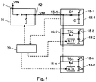
- Fig. 1 the parts of a first embodiment of an inductive switching power supply relevant to the invention are illustrated.
- the inductive switching power supply has a switching, inductive DC / DC converter 10 in a buck converter topology.
- a supply voltage VIN which is, for example, a rectified mains voltage, is fed to an input 11 of the DC / DC converter 10.
- the corresponding AC / DC converter of the switching power supply is in Fig. 1 not shown.
- the DC / DC converter 10 provides an intermediate voltage VM at its output 12.
- the inductive switching power supply also has a first output circuit 14-1, the input 16-1 of which is connected to the output 12 of the DC / DC converter 10 and an output voltage V1 is provided at the output 18-1.
- the output 18-1 is only connected to the input 16-1 via a diode D1 in order to ensure that the current is freewheeling.
- the first output circuit 14-1 has a capacitor C1 for setting the output voltage V1.
- the output voltage V1 of the first output circuit 14-1 is the output voltage of the switching power supply with the highest voltage level.
- the inductive switching power supply also has one or more further output circuits 14-2 ... 14-n.
- the number of these further output circuits 14-2 ... 14-n is basically arbitrary.
- the inputs 16-2 ... 16-n of the further output circuits 14-2 ... 14-n are also each connected to the output 12 of the DC / DC converter 10.
- an output voltage V2 ... Vn is provided, the voltage level of which is set via a capacitor C2 ... Cn. Since the capacitances of the capacitors C1 ... Cn of all output circuits 14-1 ... 14-n are different from one another, the voltage levels of the output voltages V1 ... Vn of the output circuits 14-1 ... 14-n are also different from one another.
- the voltage level of the output voltage V1 of the first output circuit 14-1 is, for example, +15 V and the voltage level of the output voltage V2 of a further output circuit 14-2 is, for example, +5 V.
- the further output circuit 14-2 can then optionally be a preferred one only a single-stage linear regulator must be connected in order to lower the voltage level to +3.3 V, for example.
- the further output circuits 14-2 ... 14-n also each have a switching element TS2 ... TSn in the form of a transistor between their input 16-2 ... 16-n and their output 18-2 ... 18-n .
- the switching elements TS2 ... TSn are each operated by a driver GT2 ... GTn in the form of a gate driver.
- the switching power supply also has a controller 20.
- This controller 20 controls the DC / DC converter 10, in particular its switching element, in order to regulate the intermediate voltage VM.
- the controller 20 controls the drivers GT2 ... GTn of the further output circuits 14-2 ... 14-n in order to actuate their switching elements TS2 ... TSn.
- the controller 20 can also be given feedback about the output voltage V1 of the first output circuit 14-1 in order to regulate the intermediate voltage VM.
- the controller 20 can also be given feedback about the output voltage V2 ... Vn of one or more further output circuits 14-2 ... 14-n.
- these can for example be from the levels of the several output voltages can be combined analogously or digitally combined as an OR connection of the results of the voltage threshold tests.
- these can optionally be connected to the input 16 via a diode (not shown) -2 ... 16-n of the further output circuit 14-2 ... 14-n can be connected.
- the output voltages V2 ... Vn of the further output circuits 14-2 ... 14-n are usually regulated at their voltage levels.
- a hysteresis in the voltage control can be useful. Such a hysteresis can also be used to set the compromise between control accuracy and switching losses.
- controller 20 regulates the switched-mode power supply exclusively to the maximum output voltage level V1 of the first output circuit 14-1, then it may be expedient to separate the output 18-1 from the DC / DC converter 10 via the diode D1 at least partially canceled by a parallel resistor (not shown).
- the additional resistor thus acts as a base load, which limits the maximum switch-off time of the switching power supply and already supplies a smaller output voltage V2 ... Vn to be recharged.
- Fig. 2 shows the parts of a second embodiment of an inductive switching power supply relevant to the invention.
- the switching power supply from Fig. 2 differs from that of the first exemplary embodiment in that the switching, inductive DC / DC converter 10 ′ is configured in a step-up converter topology. Otherwise, the switching power supply corresponds to Fig. 2 and its operation as that of the first embodiment of Fig. 1 .
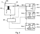
- Fig. 3 shows the parts of a third embodiment of an inductive switching power supply relevant to the invention.
- the switching power supply from Fig. 3 differs from that of the first exemplary embodiment in that the switching, inductive DC / DC converter 10 ′′ is designed in a flyback topology. Otherwise, the switching power supply corresponds to FIG Fig. 3 and its mode of operation also corresponds to that of the first exemplary embodiment of Fig. 1 .
Abstract
Ein induktives Schaltnetzteil weist einen schaltenden, induktiven DC/DC-Konverter (10; 10'; 10") mit einem Eingang (11), über den eine Versorgungsspannung (VIN) zugeführt werden kann, und einem Ausgang (12) zum Bereitstellen einer Zwischenspannung (VM) sowie eine erste Ausgangsschaltung (14-1) mit einem Eingang (16-1), der mit dem Ausgang (12) des DC/DC-Konverters (10; 10'; 10") verbunden ist, und einem Ausgang (18-1) zum Bereitstellen einer Ausgangsspannung (V1) auf. Das erfindungsgemäße induktive Schaltnetzteil weist zudem wenigstens eine weitere Ausgangsschaltung (14-2 ... 14-n) auf, die einen mit dem Ausgang (12) des DC/DC-Konverters (10; 10'; 10") verbundenen Eingang (16-2 ... 16n) und einen Ausgang (18-2 ...18-n) zum Bereitstellen einer von der Ausgangsspannung (V1) der ersten Ausgangsschaltung (14-1) verschiedenen Ausgangsspannung (V2 ... Vn) aufweist.An inductive switching power supply has a switching, inductive DC / DC converter (10; 10 '; 10 ") with an input (11) via which a supply voltage (VIN) can be supplied and an output (12) for providing an intermediate voltage (VM) and a first output circuit (14-1) with an input (16-1), which is connected to the output (12) of the DC / DC converter (10; 10 '; 10 "), and an output ( 18-1) to provide an output voltage (V1). The inductive switching power supply according to the invention also has at least one further output circuit (14-2 ... 14-n) which has an input (16.) Connected to the output (12) of the DC / DC converter (10; 10 '; 10 ") -2 ... 16n) and an output (18-2 ... 18-n) for providing an output voltage (V2 ... Vn) different from the output voltage (V1) of the first output circuit (14-1).
Description
Die vorliegende Erfindung betrifft ein induktives Schaltnetzteil zum Erzeugen mehrerer geregelter Ausgangsspannungen.The present invention relates to an inductive switching power supply for generating a plurality of regulated output voltages.
Das Prinzip eines induktiven Schaltnetzteils beruht darauf, eine Wicklung durch Anlegen einer Versorgungsspannung zu laden, die Versorgungsspannungszufuhr anschließend abzuschalten und den eingeprägten Strom dann der Ausgangsspannung zuzuführen. Herkömmliche induktive Schaltnetzteile liefern jeweils eine Ausgangsspannung je Wicklung. Die
Es ist die Aufgabe der Erfindung, ein verbessertes induktives Schaltnetzteil zu schaffen, mit dem mehrere unterschiedliche Ausgangsspannungen bereitgestellt werden können.It is the object of the invention to provide an improved inductive switching power supply with which several different output voltages can be provided.
Diese Aufgabe wird gelöst durch ein induktives Schaltnetzteil mit den Merkmalen des Anspruchs 1. Besonders vorteilhafte Ausgestaltungen und Weiterbildungen der Erfindung sind Gegenstand der abhängigen Ansprüche.This object is achieved by an inductive switching power supply with the features of claim 1. Particularly advantageous refinements and developments of the invention are the subject of the dependent claims.
Das induktive Schaltnetzteil der Erfindung hat einen schaltenden, induktiven DC/DC-Konverter mit einem Eingang, über den eine Versorgungsspannung zugeführt werden kann, und einem Ausgang zum Bereitstellen einer Zwischenspannung; eine erste Ausgangsschaltung mit einem mit dem Ausgang des DC/DC-Konverters verbundenen Eingang und einem Ausgang zum Bereitstellen einer Ausgangsspannung; und wenigstens eine weitere Ausgangsschaltung, die einen mit dem Ausgang des DC/DC-Konverters verbundenen Eingang und einen Ausgang zum Bereitstellen einer von der Ausgangsspannung der ersten Ausgangsschaltung verschiedenen Ausgangsspannung aufweist.The inductive switched-mode power supply of the invention has a switching, inductive DC / DC converter with an input via which a supply voltage can be supplied and an output for providing an intermediate voltage; a first output circuit with an input connected to the output of the DC / DC converter and an output for providing an output voltage; and at least one further output circuit which has an input connected to the output of the DC / DC converter and an output for providing an output voltage which is different from the output voltage of the first output circuit.
Durch das Anschließen mehrerer Ausgangsschaltungen an den Ausgang des DC/DC-Konverters können bei dem erfindungsgemäßen Schaltnetzteil mit nur einer Wicklung mehrere unterschiedliche, geregelte Ausgangsspannungen bereitgestellt werden. Durch den Verzicht auf zusätzliche Wicklungen bzw. Induktivitäten wird ein einfacher und kostengünstiger Aufbau des induktiven Schaltnetzteils ermöglicht.By connecting several output circuits to the output of the DC / DC converter, the switching power supply according to the invention can be used with only one winding several different, regulated output voltages are provided. By dispensing with additional windings or inductors, a simple and inexpensive construction of the inductive switching power supply is made possible.
Ein weiterer Vorteil des erfindungsgemäßen induktiven Schaltnetzteils besteht darin, dass die mehreren Ausgangsspannungen durch die individuellen Ausgangsschaltungen einzeln geregelt werden können. Außerdem entsteht durch die individuellen Ausgangsschaltungen eine größere Flexibilität, da durch Verändern einer oder mehrerer Ausgangsschaltungen und/oder durch Hinzufügen weiterer Ausgangsschaltungen die Spannungsniveaus und die Anzahl der vom Schaltnetzteil bereitgestellten Ausgangsspannungen auf einfache Weise geändert werden können, ohne den Konverter und/oder den Grundschaltungsaufbau des Schaltnetzteils modifizieren zu müssen. Auch muss durch die individuellen Ausgangsschaltungen nur eine geringere Variantenvielfalt an Schaltnetzteilen für verschiedene Anwendungen bereitgehalten werden.Another advantage of the inductive switching power supply according to the invention is that the plurality of output voltages can be regulated individually by the individual output circuits. In addition, the individual output circuits provide greater flexibility, since by changing one or more output circuits and / or by adding further output circuits, the voltage levels and the number of output voltages provided by the switching power supply can be changed in a simple manner without the converter and / or the basic circuit structure of the Need to modify switching power supply. The individual output circuits also only require a smaller variety of switching power supplies for different applications.
Ein weiterer Vorteil des erfindungsgemäßen induktiven Schaltnetzteils besteht darin, dass mit nur einer vorhandenen Wicklung auch solche Ausgangsspannungen bereitgestellt werden können, dass auf einen nachgeschalteten Linearregler verzichtet werden kann oder die von einem nachgeschalteten Linearregler zu überbrückende Spannung reduziert werden kann. Als Folge davon können erforderliche Kühlungsmaßnahmen reduziert werden, wodurch die benötigte Kühlfläche verkleinert und Standbyverluste verringert werden können, was zu einem platzsparenden und kostengünstigen Aufbau des Schaltnetzteils führt. Außerdem hat der geringere Leistungsverbrauch im nachgeschalteten Linearregler einen geringeren Stromabfall zum Laden der Ausgangskapazitäten zur Folge, sodass sich dieser näher an der Abschaltschwelle bewegen kann und die verfügbare Ausgangsleistung leicht erhöht ist.Another advantage of the inductive switched-mode power supply according to the invention is that output voltages can also be provided with only one winding, so that a downstream linear regulator can be dispensed with or the voltage to be bridged by a downstream linear regulator can be reduced. As a result, the required cooling measures can be reduced, as a result of which the required cooling area can be reduced and standby losses can be reduced, which leads to a space-saving and inexpensive construction of the switching power supply. In addition, the lower power consumption in the downstream linear controller results in a lower current drop for charging the output capacities, so that it can move closer to the switch-off threshold and the available output power is slightly increased.
In einer Ausgestaltung der Erfindung weist die wenigstens eine weitere Ausgangsschaltung zwischen ihrem Eingang und ihrem Ausgang ein Schaltelement, vorzugsweise in Form eines Transistors, zum wahlweisen Zuschalten der weiteren Ausgangsschaltung auf. In diesem Fall weist die wenigstens eine weitere Ausgangsschaltung bevorzugt zudem einen Treiber, vorzugsweise in Form eines Gate-Treibers, zum Betätigen des Schaltelements auf. Optional kann die wenigstens eine weitere Ausgangsschaltung bei dieser Ausgestaltung zwischen ihrem Eingang und ihrem Schaltelement ferner eine Diode aufweisen, sodass beim Zuschalten mehrerer Ausgangsspannungen negative Spannungen an den Schaltelementen vermieden werden können.In one embodiment of the invention, the at least one further output circuit has a switching element between its input and its output, preferably in the form of a transistor, for the optional connection of the further output circuit. In this case, the at least one further output circuit preferably also has a driver, preferably in the form of a gate driver, for actuating the switching element. Optionally, the at least one further output circuit can be used this embodiment also have a diode between its input and its switching element, so that negative voltages on the switching elements can be avoided when connecting a plurality of output voltages.
In einer Ausgestaltung der Erfindung weist die erste Ausgangsschaltung zwischen ihrem Eingang und ihrem Ausgang eine Diode auf, um den Freilauf des Stroms zu gewährleisten. Alternativ oder zusätzlich kann die erste Ausgangsschaltung analog zu der wenigstens einen weiteren Ausgangsschaltung auch ein Schaltelement zum wahlweisen Zuschalten der ersten Ausgangsschaltung aufweisen.In one embodiment of the invention, the first output circuit has a diode between its input and its output in order to ensure that the current freewheels. As an alternative or in addition, the first output circuit can also have a switching element for selectively connecting the first output circuit in a manner analogous to the at least one further output circuit.
Zum Bereitstellen der unterschiedlichen Ausgangsspannungen sind die Ausgangsschaltungen vorzugsweise jeweils mit einem Spannungsteiler ausgestattet. In einer Ausgestaltung der Erfindung weisen die erste Ausgangsschaltung und die wenigstens eine weitere Ausgangsschaltung jeweils einen Kondensator zum Einstellen des Spannungsniveaus der Ausgangsspannung auf, wobei die Kapazitäten der Kondensatoren der ersten und der wenigstens einen weiteren Ausgangsschaltung unterschiedlich zueinander sind.To provide the different output voltages, the output circuits are preferably each equipped with a voltage divider. In one embodiment of the invention, the first output circuit and the at least one further output circuit each have a capacitor for setting the voltage level of the output voltage, the capacitances of the capacitors of the first and the at least one further output circuit being different from one another.
Der schaltende, induktive DC/DC-Konverter des erfindungsgemäßen Schaltnetzteils ist auf keine spezielle Topologie beschränkt. Vorzugsweise wird ein DC/DC-Konverter in Tiefsetzsteller-Topologie, ein DC/DC-Konverter in Hochsetzsteller-Topologie oder ein DC/DC-Konverter in Flyback-Topologie verwendet.The switching, inductive DC / DC converter of the switching power supply according to the invention is not restricted to any special topology. A DC / DC converter in a step-down converter topology, a DC / DC converter in a step-up converter topology or a DC / DC converter in a flyback topology is preferably used.
In einer Ausgestaltung der Erfindung kann dem Ausgang der ersten Ausgangsschaltung und/oder der wenigstens einen weiteren Ausgangsschaltung ein Linearregler nachgeschaltet sein, mit dem die jeweilige Ausgangsspannung weiter abgesenkt werden kann.In one embodiment of the invention, the output of the first output circuit and / or the at least one further output circuit can be followed by a linear regulator, with which the respective output voltage can be further reduced.
In einer weiteren Ausgestaltung der Erfindung ist eine Steuerung zum Ansteuern des Schaltelements bzw. dessen Treibers vorgesehen, wobei die Steuerung ausgestaltet ist, um einen Schaltvorgang des Schaltelements im Bereich eines Stromnulldurchgangs zu bewirken. Auf diese Weise können Schaltverluste reduziert werden.In a further embodiment of the invention, a controller is provided for actuating the switching element or its driver, the controller being designed to effect a switching operation of the switching element in the region of a current zero crossing. Switching losses can be reduced in this way.
In einer noch weiteren Ausgestaltung der Erfindung ist eine Steuerung zum Ansteuern des Schaltelements bzw. dessen Treibers vorgesehen, wobei die Steuerung ausgestaltet ist, um eine Hysterese beim Wechsel zwischen den Ausgangsspannungen der ersten und der wenigstens einen weiteren Ausgangsschaltung zu bewirken. Auf diese Weise kann ein zu häufiges Schalten oder gar ein Linearbetrieb der Schaltelemente vermieden werden.In a still further embodiment of the invention, a controller is provided for actuating the switching element or its driver, the controller being designed to cause a hysteresis when changing between the output voltages of the first and the at least one further output circuit. In this way Too frequent switching or even linear operation of the switching elements can be avoided.
Obige sowie weitere Merkmale und Vorteile der Erfindung werden aus der nachfolgenden Beschreibung bevorzugter, nicht-einschränkender Ausführungsbeispiele anhand der beiliegenden Zeichnung besser verständlich. Darin zeigen, größtenteils schematisch:
- Fig. 1
- ein vereinfachtes Teilschaltbild eines induktiven Schaltnetzteils gemäß einem ersten Ausführungsbeispiel der vorliegenden Erfindung;
- Fig. 2
- ein vereinfachtes Teilschaltbild eines induktiven Schaltnetzteils gemäß einem zweiten Ausführungsbeispiel der vorliegenden Erfindung; und
- Fig. 3
- ein vereinfachtes Teilschaltbild eines induktiven Schaltnetzteils gemäß einem dritten Ausführungsbeispiel der vorliegenden Erfindung.
- Fig. 1
- a simplified partial circuit diagram of an inductive switching power supply according to a first embodiment of the present invention;
- Fig. 2
- a simplified partial circuit diagram of an inductive switching power supply according to a second embodiment of the present invention; and
- Fig. 3
- a simplified partial circuit diagram of an inductive switching power supply according to a third embodiment of the present invention.
In
Das induktive Schaltnetzteil hat einen schaltenden, induktiven DC/DC-Konverter 10 in Tiefsetzsteller-Topologie. An einem Eingang 11 des DC/DC-Konverters 10 wird diesem eine Versorgungsspannung VIN zugeführt, bei der es sich beispielsweise um eine gleichgerichtete Netzspannung handelt. Der entsprechende AC/DC-Konverter des Schaltnetzteils ist in
Das induktive Schaltnetzteil hat ferner eine erste Ausgangsschaltung 14-1, deren Eingang 16-1 mit dem Ausgang 12 des DC/DC-Konverters 10 verbunden ist und an deren Ausgang 18-1 eine Ausgangsspannung V1 bereitgestellt wird. Der Ausgang 18-1 ist lediglich über eine Diode D1 mit dem Eingang 16-1 verbunden, um den Freilauf des Stroms zu gewährleisten. Zum Einstellen der Ausgangsspannung V1 verfügt die erste Ausgangsschaltung 14-1 über einen Kondensator C1. Bei der Ausgangsspannung V1 der ersten Ausgangsschaltung 14-1 handelt es sich in diesem Ausführungsbeispiel um die Ausgangsspannung des Schaltnetzteils mit dem höchsten Spannungsniveau.The inductive switching power supply also has a first output circuit 14-1, the input 16-1 of which is connected to the
Wie in
In einer Ausführungsform beträgt das Spannungsniveau der Ausgangsspannung V1 der ersten Ausgangsschaltung 14-1 zum Beispiel +15 V und beträgt das Spannungsniveau der Ausgangsspannung V2 einer weiteren Ausgangsschaltung 14-2 zum Beispiel +5 V. Der weiteren Ausgangsschaltung 14-2 kann dann optional ein vorzugsweise nur einstufiger Linearregler nachgeschaltet sein, um das Spannungsniveau auf zum Beispiel +3,3 V abzusenken.In one embodiment, the voltage level of the output voltage V1 of the first output circuit 14-1 is, for example, +15 V and the voltage level of the output voltage V2 of a further output circuit 14-2 is, for example, +5 V. The further output circuit 14-2 can then optionally be a preferred one only a single-stage linear regulator must be connected in order to lower the voltage level to +3.3 V, for example.
Die weiteren Ausgangsschaltungen 14-2 ... 14-n haben ferner jeweils ein Schaltelement TS2 ... TSn in Form eines Transistors zwischen ihrem Eingang 16-2 ... 16-n und ihrem Ausgang 18-2 ... 18-n. Die Schaltelemente TS2 ... TSn werden jeweils von einem Treiber GT2 ... GTn in Form eines Gate-Treibers betätigt.The further output circuits 14-2 ... 14-n also each have a switching element TS2 ... TSn in the form of a transistor between their input 16-2 ... 16-n and their output 18-2 ... 18-n . The switching elements TS2 ... TSn are each operated by a driver GT2 ... GTn in the form of a gate driver.
Wie in
Optional kann der Steuerung 20 zudem ein Feedback über die Ausgangsspannung V1 der ersten Ausgangsschaltung 14-1 gegeben werden, um die Zwischenspannung VM zu regeln. Alternativ oder zusätzlich kann der Steuerung 20 auch ein Feedback über die Ausgangsspannung V2 ... Vn einer oder mehrerer weiterer Ausgangsschaltungen 14-2 ... 14-n gegeben werden. Im Fall mehrerer Feedbacks können diese zum Beispiel aus den Niveaus der mehreren Ausgangsspannungen analog kombiniert werden oder als ODER-Verbindung der Ergebnisse der Spannungsschwellenprüfungen digital kombiniert werden.Optionally, the
Sind alle Schaltelemente TS2 ... TSn der weiteren Ausgangsschaltungen 14-2 ... 14-n ausgeschaltet bzw. offen, so fließt der Strom von der Wicklung des DC/DC-Konverters 10 über die Diode D1 zum Ausgang 18-1 der ersten Ausgangsschaltung 14-1. Wird eines der Schaltelemente TS2 ... TSn der weiteren Ausgangsschaltungen 14-2 ... 14-n eingeschaltet bzw. geschlossen, dann fließt der Strom von der Wicklung des DC/DC-Konverters 10 über dieses eingeschaltete Schaltelement zum Ausgang 18-2 ... 18-n bzw. zum Kondensator C2 ... Cn der jeweiligen weiteren Ausgangsschaltung 14-2 ... 14-n. D.h. der im induktiven DC/DC-Konverter 10 eingeprägte Strom kann so wahlweise unterschiedlichen Ausgangsspannungen V1 ... Vn zugeführt werden, sodass aus nur einer Wicklung im DC/DC-Konverter 10 auf einfache und kostengünstige Weise mehrere geregelte Ausgangsspannungen erzeugt werden können. Bei einer entsprechenden Ansteuerung der Schaltelemente TS2 ... TSn können auf diese Weise grundsätzlich beliebig viele Ausgangsspannungen V2 ... Vn geladen werden.If all switching elements TS2 ... TSn of the further output circuits 14-2 ... 14-n are switched off or open, the current flows from the winding of the DC /
Um negative Spannungen an den Schaltelementen TS2 ... TSn der weiteren Ausgangsschaltungen 14-2 ... 14-n beim Zuschalten mehrerer Ausgangsspannungen V2 ... Vn zu vermeiden, können diese optional zusätzlich über eine Diode (nicht dargestellt) mit dem Eingang 16-2 ... 16-n der weiteren Ausgangsschaltung 14-2 ... 14-n verbunden werden.In order to avoid negative voltages at the switching elements TS2 ... TSn of the further output circuits 14-2 ... 14-n when connecting several output voltages V2 ... Vn, these can optionally be connected to the
Die Ausgangsspannungen V2 ... Vn der weiteren Ausgangsschaltungen 14-2 ... 14-n werden üblicherweise auf deren Spannungsniveaus geregelt. Um Schaltverluste zu reduzieren, ist es von Vorteil, die Schaltelemente TS2 ... TSn so anzusteuern, dass sie in den Stromnulldurchgängen ein- oder ausgeschaltet werden. Um ein zu häufiges Schalten oder gar einen Linearbetrieb der Schaltelemente TS2 ... TSn zu vermeiden, kann eine Hysterese in der Spannungsregelung zweckmäßig sein. Über eine solche Hysterese lässt sich auch der Kompromiss aus Regelgenauigkeit und Schaltverlusten einstellen.The output voltages V2 ... Vn of the further output circuits 14-2 ... 14-n are usually regulated at their voltage levels. In order to reduce switching losses, it is advantageous to control the switching elements TS2 ... TSn in such a way that they are switched on or off in the zero current crossings. In order to avoid switching the TS2 ... TSn switching elements too often or even linearly, a hysteresis in the voltage control can be useful. Such a hysteresis can also be used to set the compromise between control accuracy and switching losses.
Regelt die Steuerung 20 das Schaltnetzteil ausschließlich auf das maximale Ausgangsspannungsniveau V1 der ersten Ausgangsschaltung 14-1, dann kann es zweckmäßig sein, die Trennung des Ausgangs 18-1 vom DC/DC-Konverter 10 über die Diode D1 durch einen parallel geschalteten Widerstand (nicht dargestellt) zumindest teilweise aufzuheben. Der zusätzliche Widerstand agiert so als eine Grundlast, welche die maximale Ausschaltdauer des Schaltnetzteils begrenzt und eine nachzuladende kleinere Ausgangsspannung V2 ... Vn bereits etwas versorgt.If the
Das Schaltnetzteil von
Das Schaltnetzteil von
Die Aufbauten und Funktionsweisen der verschiedenen Topologien des DC/DC-Konverters 10, 10', 10" sind dem Fachmann hinlänglich bekannt, weshalb auf eine nähere Erläuterung verzichtet werden kann.The structures and functions of the different topologies of the DC /
- 1010th
- DC/DC-Konverter (Tiefsetzsteller-Topologie)DC / DC converter (buck converter topology)
- 10'10 '
- DC/DC-Konverter (Hochsetzsteller-Topologie)DC / DC converter (step-up converter topology)
- 10"10 "
- DC/DC-Konverter (Flyback-Topologie)DC / DC converter (flyback topology)
- 1111
- Eingang von 10, 10', 10"Input from 10, 10 ', 10 "
- 1212th
- Ausgang von 10, 10', 10"Output from 10, 10 ', 10 "
- 14-114-1
- erste Ausgangsschaltungfirst output circuit
- 14-214-2
- zweite Ausgangsschaltungsecond output circuit
- 14-n14-n
- n-te Ausgangsschaltungnth output circuit
- 16-116-1
- Eingang von 14-1Entrance from 14-1
- 16-216-2
- Eingang von 14-2Entrance from 14-2
- 16-n16-n
- Eingang von 14-nEntrance from 14-n
- 18-118-1
- Ausgang von 14-1Exit from 14-1
- 18-218-2
- Ausgang von 14-2Exit from 14-2
- 18-n18-n
- Ausgang von 14-nExit from 14-n
- 2020th
- Steuerungcontrol
- C1C1
- Kondensator von 14-1Capacitor from 14-1
- C2C2
- Kondensator von 14-2Capacitor from 14-2
- CnCn
- Kondensator von 14-nCapacitor of 14-n
- D1D1
- Diode von 14-1Diode from 14-1
- GT2GT2
- Treiber, insbes. Gate-Treiber für TS2Driver, esp. Gate driver for TS2
- GTnGTn
- Treiber, insbes. Gate-Treiber für TSnDrivers, especially gate drivers for TSn
- TS2TS2
- Schaltelement, insbes. Transistor von 14-2Switching element, in particular transistor from 14-2
- TSnTSn
- Schaltelement, insbes. Transistor von 14-nSwitching element, in particular transistor of 14-n
- VINVIN
- VersorgungsspannungSupply voltage
- VMVM
- ZwischenspannungIntermediate voltage
- V1V1
- Ausgangsspannung von 14-1Output voltage from 14-1
- V2V2
- Ausgangsspannung von 14-2Output voltage from 14-2
- VnVn
- Ausgangsspannung von 14-nOutput voltage of 14-n
Claims (10)
die wenigstens eine weitere Ausgangsschaltung (14-2 ... 14-n) zwischen ihrem Eingang (16-2 ... 16-n) und ihrem Ausgang (18-2 ... 18-n) ein Schaltelement (TS2 ... TSn) zum wahlweisen Zuschalten der weiteren Ausgangsschaltung (14-2 ... 14-n) aufweist.An inductive switching power supply according to claim 1, in which
the at least one further output circuit (14-2 ... 14-n) between its input (16-2 ... 16-n) and its output (18-2 ... 18-n) is a switching element (TS2 .. . TSn) for optional connection of the further output circuit (14-2 ... 14-n).
die wenigstens eine weitere Ausgangsschaltung (14-2 ... 14-n) einen Treiber (GT2 ... GTn) zum Betätigen des Schaltelements (TS2 ... TSn) aufweist.Inductive switching power supply according to claim 2, wherein
the at least one further output circuit (14-2 ... 14-n) has a driver (GT2 ... GTn) for actuating the switching element (TS2 ... TSn).
die wenigstens eine weitere Ausgangsschaltung (14-2 ... 14-n) zwischen ihrem Eingang (16-2 ... 16-n) und ihrem Schaltelement (TS2 ... TSn) eine Diode aufweist.Inductive switching power supply according to claim 2 or 3, wherein
the at least one further output circuit (14-2 ... 14-n) has a diode between its input (16-2 ... 16-n) and its switching element (TS2 ... TSn).
Priority Applications (1)
| Application Number | Priority Date | Filing Date | Title |
|---|---|---|---|
| EP18000746.0A EP3627681A1 (en) | 2018-09-19 | 2018-09-19 | Single inductor multiple output (simo) switch mode power converter |
Applications Claiming Priority (1)
| Application Number | Priority Date | Filing Date | Title |
|---|---|---|---|
| EP18000746.0A EP3627681A1 (en) | 2018-09-19 | 2018-09-19 | Single inductor multiple output (simo) switch mode power converter |
Publications (1)
| Publication Number | Publication Date |
|---|---|
| EP3627681A1 true EP3627681A1 (en) | 2020-03-25 |
Family
ID=63667671
Family Applications (1)
| Application Number | Title | Priority Date | Filing Date |
|---|---|---|---|
| EP18000746.0A Withdrawn EP3627681A1 (en) | 2018-09-19 | 2018-09-19 | Single inductor multiple output (simo) switch mode power converter |
Country Status (1)
| Country | Link |
|---|---|
| EP (1) | EP3627681A1 (en) |
Cited By (3)
| Publication number | Priority date | Publication date | Assignee | Title |
|---|---|---|---|---|
| CN111769751A (en) * | 2020-05-15 | 2020-10-13 | 海信(山东)空调有限公司 | Direct current power supply circuit and air conditioner |
| CN113098265A (en) * | 2021-04-13 | 2021-07-09 | 苏州力生美半导体有限公司 | Single-inductor double-output BUCK switching power supply and charge-discharge control method thereof |
| CN117240087A (en) * | 2023-11-14 | 2023-12-15 | 苏州越禾泰普数据科技有限公司 | Control method, device and system of single-input multi-output direct current-to-direct current circuit |
Citations (6)
| Publication number | Priority date | Publication date | Assignee | Title |
|---|---|---|---|---|
| US5617015A (en) * | 1995-06-07 | 1997-04-01 | Linear Technology Corporation | Multiple output regulator with time sequencing |
| US6549432B1 (en) * | 2002-02-28 | 2003-04-15 | Koninklijke Philips Electronics N.V. | Single-winding, multiple-output, bi-directional flyback converter |
| DE10218456A1 (en) | 2002-04-25 | 2003-11-06 | Abb Patent Gmbh | Switching power supply arrangement |
| DE10259353A1 (en) * | 2002-12-18 | 2004-07-22 | Infineon Technologies Ag | Generating number of regulated direct voltages from common input voltage involves alternately supplying at least two charge storage devices from inductive storage device |
| EP1465329A2 (en) * | 2003-04-01 | 2004-10-06 | Matsushita Electric Industrial Co., Ltd. | Multi-output DC-DC converter |
| DE102009000395A1 (en) * | 2009-01-23 | 2010-07-29 | Robert Bosch Gmbh | Electronic switching regulator i.e. down converter, for electrical supply of control device in motor vehicle, has switch switching current flowing via coil, where current is separated into two paths guided to outputs at output-sided node |
-
2018
- 2018-09-19 EP EP18000746.0A patent/EP3627681A1/en not_active Withdrawn
Patent Citations (6)
| Publication number | Priority date | Publication date | Assignee | Title |
|---|---|---|---|---|
| US5617015A (en) * | 1995-06-07 | 1997-04-01 | Linear Technology Corporation | Multiple output regulator with time sequencing |
| US6549432B1 (en) * | 2002-02-28 | 2003-04-15 | Koninklijke Philips Electronics N.V. | Single-winding, multiple-output, bi-directional flyback converter |
| DE10218456A1 (en) | 2002-04-25 | 2003-11-06 | Abb Patent Gmbh | Switching power supply arrangement |
| DE10259353A1 (en) * | 2002-12-18 | 2004-07-22 | Infineon Technologies Ag | Generating number of regulated direct voltages from common input voltage involves alternately supplying at least two charge storage devices from inductive storage device |
| EP1465329A2 (en) * | 2003-04-01 | 2004-10-06 | Matsushita Electric Industrial Co., Ltd. | Multi-output DC-DC converter |
| DE102009000395A1 (en) * | 2009-01-23 | 2010-07-29 | Robert Bosch Gmbh | Electronic switching regulator i.e. down converter, for electrical supply of control device in motor vehicle, has switch switching current flowing via coil, where current is separated into two paths guided to outputs at output-sided node |
Cited By (4)
| Publication number | Priority date | Publication date | Assignee | Title |
|---|---|---|---|---|
| CN111769751A (en) * | 2020-05-15 | 2020-10-13 | 海信(山东)空调有限公司 | Direct current power supply circuit and air conditioner |
| CN113098265A (en) * | 2021-04-13 | 2021-07-09 | 苏州力生美半导体有限公司 | Single-inductor double-output BUCK switching power supply and charge-discharge control method thereof |
| CN113098265B (en) * | 2021-04-13 | 2022-02-08 | 苏州力生美半导体有限公司 | Single-inductor double-output BUCK switching power supply and charge-discharge control method thereof |
| CN117240087A (en) * | 2023-11-14 | 2023-12-15 | 苏州越禾泰普数据科技有限公司 | Control method, device and system of single-input multi-output direct current-to-direct current circuit |
Similar Documents
| Publication | Publication Date | Title |
|---|---|---|
| DE60003276T2 (en) | DC / DC converter and method for operating a DC / DC converter | |
| DE60224896T2 (en) | Circuits and methods for synchronizing non-constant frequency switching regulators by a phase locked loop | |
| WO2008116866A1 (en) | Voltage convertor with connected capacitors and device for the compensation of the capacitors voltages | |
| DE112014004225T5 (en) | Charge pumps timing | |
| DE102013213625A1 (en) | Multiphase digital current-mode controller with dynamic current allocation | |
| DE102011052922A1 (en) | Multi-phase DC-DC converter with a plurality of mutually parallel-connected converter circuits | |
| EP3627681A1 (en) | Single inductor multiple output (simo) switch mode power converter | |
| DE19931059C2 (en) | DC converter | |
| DE112016004961T5 (en) | Multiphase converter | |
| DE112017005404T5 (en) | DC-DC converter | |
| DE102014016037A1 (en) | Low power switched linear regulator | |
| EP2193534A1 (en) | Apparatus and method for supplying power to a voltage- or current-releasing switching device | |
| EP2540139A2 (en) | Led voltage measurement | |
| DE10249802A1 (en) | DC voltage converter has inductance connected to input at one end, to reference potential and output via two switches at other end, arrangement for controlling switches to regulate output voltage | |
| EP1050951B1 (en) | Circuit arrangement for clocked power supply | |
| DE102019113858A1 (en) | Methods and devices for regulating the output voltage of a voltage regulator | |
| DE102016122191A1 (en) | Current threshold detection in synchronous control | |
| DE102011108091A1 (en) | Supply circuit and method for supplying an electrical load | |
| DE102014225195A1 (en) | DC-DC converter system, DC power supply system, and DC-DC converter system board | |
| EP1652286B1 (en) | Switched-mode power supply | |
| DE10223771A1 (en) | Switching voltage converter supplying e.g. motherboard makes direct use of digital adjustment signal to set and regulate output voltage | |
| DE102020112928A1 (en) | LED DRIVER SYSTEMS AND PROCEDURES | |
| DE3941420C1 (en) | ||
| EP1885049A1 (en) | Power supply unit with combined up/down switch transducer | |
| DE102014108775A1 (en) | Downs converter and LED device, in particular LED headlights or LED signal light, with such a buck converter |
Legal Events
| Date | Code | Title | Description |
|---|---|---|---|
| PUAI | Public reference made under article 153(3) epc to a published international application that has entered the european phase |
Free format text: ORIGINAL CODE: 0009012 |
|
| STAA | Information on the status of an ep patent application or granted ep patent |
Free format text: STATUS: THE APPLICATION HAS BEEN PUBLISHED |
|
| AK | Designated contracting states |
Kind code of ref document: A1 Designated state(s): AL AT BE BG CH CY CZ DE DK EE ES FI FR GB GR HR HU IE IS IT LI LT LU LV MC MK MT NL NO PL PT RO RS SE SI SK SM TR |
|
| AX | Request for extension of the european patent |
Extension state: BA ME |
|
| STAA | Information on the status of an ep patent application or granted ep patent |
Free format text: STATUS: THE APPLICATION IS DEEMED TO BE WITHDRAWN |
|
| 18D | Application deemed to be withdrawn |
Effective date: 20200926 |