EP3627673A1 - Segmentiertes sekundärteil für einen linearmotor - Google Patents
Segmentiertes sekundärteil für einen linearmotor Download PDFInfo
- Publication number
- EP3627673A1 EP3627673A1 EP18195710.1A EP18195710A EP3627673A1 EP 3627673 A1 EP3627673 A1 EP 3627673A1 EP 18195710 A EP18195710 A EP 18195710A EP 3627673 A1 EP3627673 A1 EP 3627673A1
- Authority
- EP
- European Patent Office
- Prior art keywords
- secondary part
- segments
- segmented secondary
- linear motor
- magnets
- Prior art date
- Legal status (The legal status is an assumption and is not a legal conclusion. Google has not performed a legal analysis and makes no representation as to the accuracy of the status listed.)
- Granted
Links
Images

Classifications
-
- H—ELECTRICITY
- H02—GENERATION; CONVERSION OR DISTRIBUTION OF ELECTRIC POWER
- H02K—DYNAMO-ELECTRIC MACHINES
- H02K41/00—Propulsion systems in which a rigid body is moved along a path due to dynamo-electric interaction between the body and a magnetic field travelling along the path
- H02K41/02—Linear motors; Sectional motors
- H02K41/03—Synchronous motors; Motors moving step by step; Reluctance motors
- H02K41/031—Synchronous motors; Motors moving step by step; Reluctance motors of the permanent magnet type
-
- H—ELECTRICITY
- H02—GENERATION; CONVERSION OR DISTRIBUTION OF ELECTRIC POWER
- H02K—DYNAMO-ELECTRIC MACHINES
- H02K11/00—Structural association of dynamo-electric machines with electric components or with devices for shielding, monitoring or protection
- H02K11/01—Structural association of dynamo-electric machines with electric components or with devices for shielding, monitoring or protection for shielding from electromagnetic fields, i.e. structural association with shields
- H02K11/014—Shields associated with stationary parts, e.g. stator cores
-
- H—ELECTRICITY
- H02—GENERATION; CONVERSION OR DISTRIBUTION OF ELECTRIC POWER
- H02K—DYNAMO-ELECTRIC MACHINES
- H02K3/00—Details of windings
- H02K3/46—Fastening of windings on the stator or rotor structure
- H02K3/47—Air-gap windings, i.e. iron-free windings
-
- H—ELECTRICITY
- H02—GENERATION; CONVERSION OR DISTRIBUTION OF ELECTRIC POWER
- H02K—DYNAMO-ELECTRIC MACHINES
- H02K2201/00—Specific aspects not provided for in the other groups of this subclass relating to the magnetic circuits
- H02K2201/15—Sectional machines
-
- H—ELECTRICITY
- H02—GENERATION; CONVERSION OR DISTRIBUTION OF ELECTRIC POWER
- H02K—DYNAMO-ELECTRIC MACHINES
- H02K2213/00—Specific aspects, not otherwise provided for and not covered by codes H02K2201/00 - H02K2211/00
- H02K2213/03—Machines characterised by numerical values, ranges, mathematical expressions or similar information
-
- H—ELECTRICITY
- H02—GENERATION; CONVERSION OR DISTRIBUTION OF ELECTRIC POWER
- H02K—DYNAMO-ELECTRIC MACHINES
- H02K2213/00—Specific aspects, not otherwise provided for and not covered by codes H02K2201/00 - H02K2211/00
- H02K2213/12—Machines characterised by the modularity of some components
Definitions
- the present invention relates to a segmented secondary part for a linear motor.
- the secondary part has a shield with which the leakage flux in the vicinity of the secondary part is reduced.
- Linear motors with an active primary part provided with coils and a passive secondary part provided with magnets are omnipresent as drives in the area of precise positioning of machine elements.
- the primary parts can have an iron core with teeth carrying bobbins, or can be made without iron.
- Such ironless linear motors are advantageous for particularly precise positioning, since they have significantly lower locking forces and no attractive forces between the primary and the secondary part.
- linear motors can generate unwanted magnetic stray fields, for example in the area of Electron microscopy or electron beam lithography are particularly disruptive because such stray fields can deflect the electrons or rays from charged particles in general.
- an ironless linear motor in which secondary parts are arranged on both sides of a movable primary part, each with a yoke plate and magnets attached thereon.
- the magnets have alternating polarity in the direction of movement of the linear motor, with opposing magnets being magnetized perpendicular to the yoke plates and in each case in the same direction.
- Various measures for reducing stray fields are proposed in this document, such as, for example, end plates and flexible, magnetically shielding sealing lips which only open the interior of the stator where the movable primary part is currently located.
- it is very complex to manufacture such a linear motor in any and in particular large lengths, because then many differently long secondary parts and in particular also very long secondary parts have to be manufactured.
- a linear motor is known, the secondary part of which consists of several segments, and which can be produced by connecting several segments in almost any length.
- This linear motor has overlapping areas at the joints between the segments, which are manufactured in such a way that an alignment of the segments to one another is brought about by the positive locking of the two segments.
- it is very complex to process the respective end areas of the segments with the necessary accuracy.
- even the smallest inaccuracies can lead to gaps and edges where stray fields can escape in an uncontrolled manner.
- a segmented secondary part of a linear motor with at least two segments, each with a plurality of magnets of alternating polarity attached to a yoke plate, the magnetization direction of which is oriented perpendicular to the yoke plate.
- the yoke plates have an overlap area in which the yoke plates of adjacent segments lie one above the other in the magnetization direction, but do not touch.
- the special design of the overlap area of the segments of the secondary part ensures that the magnetic flux inside the segments is concentratedly transmitted via a small air gap with little magnetic resistance, while in regions of the segments lying further out the air gap is larger, the flow and thus the leakage flow is also smaller. With bevels facing away from the magnet and opposite outer edges of the This magnetic resistance and thus the leakage flux escaping can be additionally reduced here.
- the Figure 1 shows a linear motor according to the prior art, with which a machine part can be moved and positioned relative to another machine part.
- a primary part P which is connected to a mounting foot F, moves between a secondary part S with two yoke plates J, which are covered with magnets M.
- This mounting foot F is connected to one of the two machine parts to be moved relative to one another, while the secondary part S is connected to the other of the two machine parts.
- the magnets M have alternating polarity in the direction of movement of the linear motor, opposing magnets are magnetized in the same direction.
- In the primary part P there are coils, which are mounted on the mounting foot F. electrical energy are supplied.
- the present invention relates to the overlap region B of two adjacent segments S1, S2. This area is considered in more detail in the following figures.
- the Figure 3 shows a section through the secondary part S, which contains both the direction of movement X of the primary part (not shown) and the magnetization direction Y of the magnets M.
- the section shows the overlapping areas B of two segments S1, S2 of the segmented secondary part S.
- the first segment S1 has a tongue Z which projects into a groove N of the second segment S2.
- the yoke plates J of the segments S1, S2 lie one above the other in the overlap area B, leakage of leakage flux through a gap between the two segments S1, S2 is made more difficult.
- the tongue Z and the groove N are preferably cuboid, since this shape can be produced particularly easily. But there are also other shapes are conceivable, for example with triangular cross sections in the XY section, or a two-layer overlap as in the one cited above EP 2774252 B1 . Overlaps with two or more projections that protrude into corresponding recesses are also within the scope of the invention.
- this overlap area B is not used to align the segments S1, S2. Rather, the segments S1, S2 do not touch, neither in the overlap area B nor otherwise.
- the tongue Z and the groove N can be produced with comparatively large tolerances and thus inexpensively
- the segments S1, S2 should be open other way to be aligned. The exact alignment is required because the regular sequence of magnets M should not be disturbed, even at the transitions from one segment S1 to the next segment S2, in order to avoid undesirable force ripples.
- the segments S1, S2 can be positioned and fastened, for example, with pins and screws which are guided through precisely aligned bores in the segments S1, S2 and in the machine part, or with stops on the machine, through special mounting devices, or on any other Wise.
- the two segments S1, S2 maintain a minimum distance of 0.5 millimeters in all directions X, Y. Even if the smallest possible distance for the magnetic flux would be desirable, this minimum distance should not fall below 0.25 millimeters, since otherwise the manufacturing effort or the necessary machining accuracy increases unnecessarily.
- this distance is chosen to be smaller than the outer distance of the segments S1, S2 in the X direction, because the tongue Z and the groove N have large areas (in the XZ Plane) is formed in the interior of the overlap region B.
- the distance in the X direction at the outer joints between the segments S1, S2 can be, for example, 0.75 millimeters.
- This magnetic resistance at the outer edges K1, K2 running in the Z direction can be increased even further if the longitudinal edges K1, K2 facing away from and opposing the magnet M of two adjacent ones Yoke plates J each have a bevel A, which, for example, remove two millimeters of material in the X and Y directions and thus form a 45 ° angle. A range of 35 ° - 55 ° for this bevel A is preferred. Since magnetic field lines always emerge perpendicular to the surface, the path that the magnetic flux has to travel through the air gap is extended, and thus the magnetic resistance in the area of the edges K1, K2 or the bevels A. Thus, a larger proportion of the flux transmitted in the interior of the overlap area B, and the leakage flux is reduced.
- the invention is suitable for secondary parts S of ironless linear motors with one-sided or, as shown, two-sided arrangement of magnetic tracks, but also for secondary parts S of iron-containing linear motors.
Landscapes
- Engineering & Computer Science (AREA)
- Power Engineering (AREA)
- Physics & Mathematics (AREA)
- Electromagnetism (AREA)
- Chemical & Material Sciences (AREA)
- Combustion & Propulsion (AREA)
- Linear Motors (AREA)
Abstract
Description
- Die vorliegende Erfindung betrifft ein segmentiertes Sekundärteil für einen Linearmotor. Das Sekundärteil weist eine Abschirmung auf, mit dem der Streufluss in der Umgebung des Sekundärteils reduziert wird.
- Linearmotoren mit einem aktiven, mit Spulen versehenen Primärteil und einem passiven, mit Magneten versehenen Sekundärteil sind als Antriebe im Bereich der genauen Positionierung von Maschinenelementen allgegenwärtig. Dabei können die Primärteile einen Eisenkern mit Spulen tragenden Zähnen aufweisen, oder eisenlos ausgeführt sein. Solche eisenlosen Linearmotoren sind für die besonders genaue Positionierung vorteilhaft, da sie wesentlich geringere Rastkräfte und keine Anziehungskräfte zwischen dem Primär- und dem Sekundärteil aufweisen.
- Wie alle elektromagnetischen Einrichtungen können solche Linearmotoren unerwünschte magnetische Streufelder erzeugen, die z.B. im Bereich der Elektronenmikroskopie oder der Elektronenstrahllithographie besonders störend wirken, weil solche Streufelder die Elektronen oder allgemein Strahlen von geladenen Partikeln ablenken können.
- Aus der
US 2010/0171375 A1 ist ein eisenloser Linearmotor bekannt, bei dem beidseits eines beweglichen Primärteils Sekundärteile mit jeweils einer Jochplatte und darauf angebrachten Magneten angeordnet sind. Die Magnete haben in der Bewegungsrichtung des Linearmotors abwechselnde Polarität, wobei sich gegenüberliegende Magnete senkrecht zu den Jochplatten und jeweils in die gleiche Richtung magnetisiert sind. In diesem Dokument werden verschiedene Maßnahmen zur Reduzierung von Streufeldern vorgeschlagen, wie beispielsweise stirnseitige Abdeckplatten und flexible, magnetisch abschirmende Dichtlippen, die das Innere des Stators nur dort öffnen, wo das bewegliche Primärteil aktuell steht. Es ist jedoch sehr aufwändig, so einen Linearmotor in beliebigen und insbesondere großen Längen herzustellen, weil dann viele verschieden lange Sekundärteile und insbesondere auch sehr lange Sekundärteile gefertigt werden müssen. - Aus der
EP 2774252 B1 ist ein Linearmotor bekannt, dessen Sekundärteil aus mehreren Segmenten besteht, und der durch Aneinanderreihung mehrerer Segmente in beinahe beliebigen Längen hergestellt werden kann. Dieser Linearmotor weist an den Stoßstellen zwischen den Segmenten überlappende Bereiche auf, die so gefertigt sind, dass durch den Formschluss der beiden Segmente eine Ausrichtung der Segmente zueinander bewirkt wird. Es ist jedoch sehr aufwändig, die jeweiligen Endbereiche der Segmente mit der nötigen Genauigkeit zu bearbeiten. Außerdem können schon kleinste Ungenauigkeiten zu Spalten und Kanten führen, an denen unkontrolliert Streufelder austreten können. - Es ist daher Aufgabe der Erfindung, einen segmentierten Stator für einen Linearmotor anzugeben, der mit weniger Aufwand zu fertigen ist, und der dennoch eine gute Abschirmung von Streufeldern an Übergängen von einem Segment zum nächsten Segment ermöglicht.
- Diese Aufgabe wird gelöst durch eine Vorrichtung gemäß Anspruch 1. Vorteilhafte Details dieser Vorrichtung ergeben sich auch aus den von Anspruch 1 abhängigen Ansprüchen.
- Es wird ein segmentiertes Sekundärteil eines Linearmotors offenbart, mit wenigstens zwei Segmenten mit jeweils einer Mehrzahl von auf einer Jochplatte befestigen Magneten abwechselnder Polarität, deren Magnetisierungsrichtung jeweils senkrecht zur Jochplatte ausgerichtet ist. Die Jochplatten weisen einen Überlappungsbereich auf, in dem die Jochplatten benachbarter Segmente in der Magnetisierungsrichtung übereinander liegen, sich aber nicht berühren.
- Auf diese Weise sind die Anforderungen an die Fertigungsgenauigkeit der Segmente des Sekundärteils reduziert, da deren Ausrichtung nicht mehr über einen Formschluss im Überlappungsbereich bewerkstelligt wird. Hierzu dienen vielmehr Schrauben und Stifte, die die einzelnen Segmente an einer Maschine ausrichten und fixieren.
- Durch die spezielle Ausgestaltung des Überlappungsbereiches der Segmente des Sekundärteils wird dafür gesorgt, dass der magnetische Fluss im Inneren der Segmente konzentriert über einen kleinen Luftspalt mit geringem magnetischen Widerstand übertragen wird, während in weiter außen liegenden Bereichen der Segmente der Luftspalt größer, der Fluss und damit auch der Streufluss kleiner ist. Mit Abschrägungen der den Magneten abgewandt und sich gegenüber liegenden äußeren Kanten der Jochplatten kann hier dieser magnetische Widerstand und damit der austretende Streufluss zusätzlich reduziert werden.
- Weitere Vorteile und Einzelheiten der vorliegenden Erfindung ergeben sich aus der nachfolgenden Beschreibung verschiedener Ausführungsformen anhand der Figuren.
- Dabei zeigt
- Figur 1
- einen Linearmotor nach dem Stand der Technik,
- Figur 2
- Jochplatten eines Sekundärteils in einer 3D-Ansicht,
- Figur 3
- Segmente eines Sekundärteils in einer geschnittenen Ansicht,
- Figur 4
- eine Vergrößerung des Überlappungsbereiches zwischen zwei Segmenten.
- Die
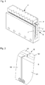
Figur 1 zeigt einen Linearmotor nach dem Stand der Technik, mit dem ein Maschinenteil relativ zu einem anderen Maschinenteil bewegt und positioniert werden kann. Zwischen einem Sekundärteil S mit zwei Jochplatten J, die mit Magneten M besetzt sind, bewegt sich ein Primärteil P, das mit einem Montagefuß F verbunden ist. Dieser Montagefuß F ist mit einem der beiden relativ zueinander zu bewegenden Maschinenteile verbunden, während das Sekundärteil S mit dem anderen der beiden Maschinenteile verbunden ist. Die Magnete M weisen in der Bewegungsrichtung des Linearmotors abwechselnde Polarität auf, sich gegenüberliegende Magnete sind in die gleiche Richtung magnetisiert. Im Primärteil P befinden sich Spulen, die über den Montagefuß F mit elektrischer Energie versorgt werden. Fließt ein Strom durch die Spulen, kann eine Kraft erzeugt werden, die das Primärteil P relativ zum Sekundärteil S mit seinen Jochplatten J und Magneten M bewegt. Der gezeigte Aufbau ist typisch für eisenlose Linearmotoren, wie sie häufig zur genauen Positionierung zum Einsatz kommen. Die beidseitige Anordnung von Magneten M erhöht den magnetischen Fluss im Bereich des Primärteils P und damit die Kraft, die der Linearmotor aufbringen kann. - Der in der
Figur 1 gezeigte Aufbau wird auch im folgenden Ausführungsbeispiel der Erfindung zugrunde gelegt. - In der
Figur 2 ist dargestellt, wie ein solches Sekundärteil S aus mehreren Segmenten S1, S2 aufgebaut werden kann. Durch das Aneinanderreihen mehrerer Segmente S1, S2 können beinahe beliebig lange Sekundärteile S hergestellt werden, ohne hierfür viele verschiedene Bauteile vorhalten zu müssen. Die Magnete M sind in dieser Ansicht weggelassen, sie sind aber in jedem der Segmente S1, S2 wie in derFigur 1 gezeigt angeordnet. - Die vorliegende Erfindung betrifft den Überlappungsbereich B von jeweils zwei benachbarten Segmenten S1, S2. Dieser Bereich wird in den folgenden Figuren näher betrachtet.
- Die
Figur 3 zeigt einen Schnitt durch das Sekundärteil S, der sowohl die Bewegungsrichtung X des (nicht dargestellten) Primärteils als auch die Magnetisierungsrichtung Y der Magnete M enthält. Der Schnitt zeigt die Überlappungsbereiche B von je zwei Segmenten S1, S2 des segmentierten Sekundärteils S. - Man erkennt, dass das erste Segment S1 eine Zunge Z aufweist, die in eine Nut N des zweiten Segments S2 ragt. Dadurch liegen die Jochplatten J der Segmente S1, S2 im Überlappungsbereich B übereinander, ein Austritt von Streufluss durch einen Spalt zwischen den beiden Segmenten S1, S2 ist erschwert.
- Bevorzugt sind die Zunge Z und die Nut N quaderförmig ausgebildet, da diese Form besonders einfach hergestellt werden kann. Es sind aber auch andere Formen denkbar, beispielsweise mit dreieckigen Querschnitten im X-Y-Schnitt, oder auch eine zweilagige Überlappung wie in der oben zitierten
EP 2774252 B1 . Auch Überlappungen mit zwei oder mehr Vorsprüngen, die in entsprechende Ausnehmungen ragen, liegen im Rahmen der Erfindung. - Wie vor allem in der in
Figur 4 gezeigten Vergrößerung des Überlappungsbereiches B zu erkennen ist, dient dieser Überlappungsbereich B nicht der Ausrichtung der Segmente S1, S2. Vielmehr berühren sich die Segmente S1, S2 nicht, und zwar weder im Überlappungsbereich B noch sonst. Das bedeutet einerseits, dass die Zunge Z und die Nut N mit vergleichsweise großen Toleranzen und damit günstig hergestellt werden können, andererseits sollten die Segmente S1, S2 auf andere Weise zueinander ausgerichtet werden. Die genaue Ausrichtung wird benötigt, weil die regelmäßige Abfolge von Magneten M auch an den Übergängen von einem Segment S1 zum nächsten Segment S2 nicht gestört werden sollte, um unerwünschte Kraftwelligkeiten zu vermeiden. Die Segmente S1, S2 können beispielsweise mit Stiften und Schrauben, die durch exakt ausgerichtete Bohrungen in den Segmenten S1, S2 und im Maschinenteil geführt sind, positioniert und befestigt werden, oder durch an der Maschine vorhandene Anschläge, durch spezielle Montagevorrichtungen, oder auf beliebige andere Weise. - In der
Figur 4 erkennt man, dass die beiden Segmente S1, S2 in allen Richtungen X, Y einen Mindestabstand von 0,5 Millimetern einhalten. Auch wenn für den magnetischen Fluss ein möglichst kleiner Abstand wünschenswert wäre, sollte dieser Mindestabstand nicht unter 0,25 Millimeter fallen, da sonst der Herstellungsaufwand bzw. die nötige Bearbeitungsgenauigkeit unnötig steigt. In Y-Richtung, also in der Magnetisierungsrichtung der Magnete M, ist dieser Abstand kleiner als der außen liegende Abstand der Segmente S1, S2 in X-Richtung gewählt, denn durch die Zunge Z und die Nut N sind hier große Flächen (in der X-Z-Ebene) im Inneren des Überlappungsbereichs B gebildet. Große Flächen mit kleinem Abstand weisen einen geringeren magnetischen Widerstand auf als kleinere Flächen mit größerem Abstand, so dass der magnetische Fluss im Inneren des Überlappungsbereiches B konzentriert wird, und damit weniger Streufluss in der Umgebung der Segmente S1, S2 des Sekundärteils S auftritt. Der Abstand in X-Richtung an den außen liegenden Stoßstellen zwischen den Segmenten S1, S2 kann beispielsweise 0,75 Millimeter betragen. - Dieser magnetische Widerstand an den außen liegenden, in Z-Richtung verlaufenden Kanten K1, K2 (die im Sinne dieser Anmeldung noch zum Überlappungsbereiche B zählen) kann noch weiter erhöht werden, wenn die den Magneten M abgewandten und sich gegenüberliegenden Längskanten K1, K2 zweier benachbarter Jochplatten J jeweils eine Abschrägung A aufweisen, die beispielsweise je zwei Millimeter Material in X- und Y-Richtung abtragen und somit einen 45° Winkel bilden. Ein Bereich von 35° - 55° für diese Abschrägung A ist bevorzugt. Da magnetische Feldlinien immer senkrecht zur Oberfläche austreten, verlängert sich hier der Weg, den der magnetische Fluss über den Luftspalt zurücklegen muss, und damit der magnetische Widerstand im Bereich der Kanten K1, K2 bzw. der Abschrägungen A. Somit wird ein größerer Anteil des Flusses im Inneren des Überlappungsbereiches B übertragen, und der Streufluss reduziert.
- Die Erfindung eignet sich für Sekundärteile S von eisenlosen Linearmotoren mit einseitiger oder wie gezeigt beidseitiger Anordnung von Magnetbahnen, aber auch für Sekundärteile S von eisenbehafteten Linearmotoren.
Claims (9)
- Segmentiertes Sekundärteil eines Linearmotors, mit wenigstens zwei Segmenten (S1, S2) mit jeweils einer Mehrzahl von auf einer Jochplatte (J) befestigen Magneten (M) abwechselnder Polarität, deren Magnetisierungsrichtung (Y) jeweils senkrecht zur Jochplatte (J) ausgerichtet ist, wobei die Jochplatten (J) einen Überlappungsbereich (B) aufweisen, in dem die Jochplatten (J) benachbarter Segmente (S1, S2) in der Magnetisierungsrichtung (Y) übereinander liegen, dadurch gekennzeichnet, dass sich die Jochplatten (J) im Überlappungsbereich (B) nicht berühren.
- Segmentiertes Sekundärteil nach Anspruch 1, dadurch gekennzeichnet, dass der Überlappungsbereich (B) zweier benachbarter Segmente (S1, S2) eine vorspringende Zunge (Z) am einen Segment (S1) und eine Nut (N) am anderen Segment (S2) umfasst, wobei im montierten Zustand die Zunge (Z) in die Nut (N) ragt.
- Segmentiertes Sekundärteil nach Anspruch 2, dadurch gekennzeichnet, dass die Zunge (Z) quaderförmig ausgebildet ist.
- Segmentiertes Sekundärteil nach einem der vorhergehenden Ansprüche, dadurch gekennzeichnet, dass zwischen zwei benachbarten Segmenten (S1, S2) und deren Jochplatten (J) in allen Richtungen ein Abstand von mindestens 0,25 mm, vorzugsweise mindestens 0,5 mm eingehalten wird.
- Segmentiertes Sekundärteil nach Anspruch 4, dadurch gekennzeichnet, dass der Abstand zwischen der Nut (N) und der Zunge (Z) in der Magnetisierungsrichtung (Y) kleiner ist als der Abstand von den Magneten (M) abgewandten und sich gegenüberliegenden Längskanten (K1, K2) zweier benachbarter Jochplatten (J) in einer Richtung (X) senkrecht zur Magnetisierungsrichtung (Y).
- Segmentiertes Sekundärteil nach Anspruch 5, dadurch gekennzeichnet, dass die den Magneten (M) abgewandten und sich gegenüberliegenden Längskanten (K1, K2) eine Abschrägung (A) aufweisen.
- Segmentiertes Sekundärteil nach Anspruch 6, dadurch gekennzeichnet, dass die Abschrägung (A) einen Winkel im Bereich von 35° bis 55° aufweist und vorzugsweise bei 45° liegt.
- Linearmotor mit einem Primärteil (P) und einem segmentierten Sekundärteil (S) nach einem der vorhergehenden Ansprüche.
- Linearmotor nach Anspruch 8, dadurch gekennzeichnet, dass sich zwei segmentierte Sekundärteile (S) gegenüberliegen, so dass die Magnete (M) einander zugewandt und sich jeweils mit identischer Magnetisierungsrichtung (Y) gegenüberliegen, und dass zwischen den Magneten (M) ein eisenloses Primärteil (P) beweglich geführt ist.
Priority Applications (2)
| Application Number | Priority Date | Filing Date | Title |
|---|---|---|---|
| EP18195710.1A EP3627673B1 (de) | 2018-09-20 | 2018-09-20 | Segmentiertes sekundärteil für einen linearmotor |
| US16/574,563 US11201534B2 (en) | 2018-09-20 | 2019-09-18 | Segmented secondary part for a linear motor |
Applications Claiming Priority (1)
| Application Number | Priority Date | Filing Date | Title |
|---|---|---|---|
| EP18195710.1A EP3627673B1 (de) | 2018-09-20 | 2018-09-20 | Segmentiertes sekundärteil für einen linearmotor |
Publications (2)
| Publication Number | Publication Date |
|---|---|
| EP3627673A1 true EP3627673A1 (de) | 2020-03-25 |
| EP3627673B1 EP3627673B1 (de) | 2023-07-26 |
Family
ID=63667777
Family Applications (1)
| Application Number | Title | Priority Date | Filing Date |
|---|---|---|---|
| EP18195710.1A Active EP3627673B1 (de) | 2018-09-20 | 2018-09-20 | Segmentiertes sekundärteil für einen linearmotor |
Country Status (2)
| Country | Link |
|---|---|
| US (1) | US11201534B2 (de) |
| EP (1) | EP3627673B1 (de) |
Families Citing this family (3)
| Publication number | Priority date | Publication date | Assignee | Title |
|---|---|---|---|---|
| CN221305610U (zh) * | 2023-11-03 | 2024-07-09 | 湖北省钻马智控科技有限公司 | 一种振动马达 |
| EP4683191A1 (de) * | 2024-07-15 | 2026-01-21 | Siemens Aktiengesellschaft | Segment für ein sekundärteil eines linearmotors, linearmotor |
| CN119231867B (zh) * | 2024-11-28 | 2025-03-14 | 克瑞科技(东莞)有限公司 | 一种小家电用的直线电机 |
Citations (7)
| Publication number | Priority date | Publication date | Assignee | Title |
|---|---|---|---|---|
| WO2004053270A1 (de) * | 2002-12-09 | 2004-06-24 | Dorma Gmbh + Co. Kg | Schiebetür |
| WO2008148305A1 (en) * | 2007-06-04 | 2008-12-11 | Lu, Hsaio-Ting | Linear motor and field magnet member thereof |
| WO2009130645A2 (en) * | 2008-04-23 | 2009-10-29 | Koninklijke Philips Electronics N.V. | Magnetic suspension positioning system |
| US20100171375A1 (en) | 2009-01-08 | 2010-07-08 | Chih-Mao Shiao | Protected Magnetic Displacement Device |
| KR20110027313A (ko) * | 2009-09-10 | 2011-03-16 | 제주대학교 산학협력단 | 초전도체를 이용한 교육용 모형 자기부상열차 키트 |
| DE202012008675U1 (de) * | 2012-09-11 | 2012-10-11 | Lothar Ginzel | Linearantrieb |
| EP2774252B1 (de) | 2011-11-02 | 2016-05-11 | Hamilton Bonaduz AG | Linearmotor mit mehreren sensoreinheiten und modularem statoraufbau |
Family Cites Families (4)
| Publication number | Priority date | Publication date | Assignee | Title |
|---|---|---|---|---|
| US6160327A (en) * | 1998-04-06 | 2000-12-12 | Kollmorgen Corporation | Winding for linear motors without slots |
| JP3688898B2 (ja) * | 1998-08-21 | 2005-08-31 | 株式会社東芝 | 電動機のロータ |
| DE10253136A1 (de) * | 2002-11-14 | 2004-05-27 | Cbp Guideway Systems Gmbh | Funktionsebenenträger |
| TWI343689B (en) * | 2006-12-28 | 2011-06-11 | Delta Electronics Inc | Permanent magnet rotary structure of electric machinery |
-
2018
- 2018-09-20 EP EP18195710.1A patent/EP3627673B1/de active Active
-
2019
- 2019-09-18 US US16/574,563 patent/US11201534B2/en active Active
Patent Citations (7)
| Publication number | Priority date | Publication date | Assignee | Title |
|---|---|---|---|---|
| WO2004053270A1 (de) * | 2002-12-09 | 2004-06-24 | Dorma Gmbh + Co. Kg | Schiebetür |
| WO2008148305A1 (en) * | 2007-06-04 | 2008-12-11 | Lu, Hsaio-Ting | Linear motor and field magnet member thereof |
| WO2009130645A2 (en) * | 2008-04-23 | 2009-10-29 | Koninklijke Philips Electronics N.V. | Magnetic suspension positioning system |
| US20100171375A1 (en) | 2009-01-08 | 2010-07-08 | Chih-Mao Shiao | Protected Magnetic Displacement Device |
| KR20110027313A (ko) * | 2009-09-10 | 2011-03-16 | 제주대학교 산학협력단 | 초전도체를 이용한 교육용 모형 자기부상열차 키트 |
| EP2774252B1 (de) | 2011-11-02 | 2016-05-11 | Hamilton Bonaduz AG | Linearmotor mit mehreren sensoreinheiten und modularem statoraufbau |
| DE202012008675U1 (de) * | 2012-09-11 | 2012-10-11 | Lothar Ginzel | Linearantrieb |
Also Published As
| Publication number | Publication date |
|---|---|
| US20200099284A1 (en) | 2020-03-26 |
| EP3627673B1 (de) | 2023-07-26 |
| US11201534B2 (en) | 2021-12-14 |
Similar Documents
| Publication | Publication Date | Title |
|---|---|---|
| EP0348403B1 (de) | Magnetisches ablenksystem für geladene teilchen | |
| DE4000666C2 (de) | Elektromagnetanordnung für einen Teilchenbeschleuniger | |
| EP2332155B1 (de) | Magnetjoch, mikromechanisches bauteil und herstellungsverfahren für ein magnetjoch und ein mikromechanisches bauteil | |
| EP3243263B1 (de) | Magnetanordnung für einen elektrischen motor | |
| EP3382412A1 (de) | Permanentmagnetanordnung für mr-apparaturen mit axial und lateral verschiebbaren, drehbar gelagerten ringbaugruppen | |
| DE19839784A1 (de) | Synchronmotor mit beweglichem Teil mit Permanentmagneten | |
| EP3627673B1 (de) | Segmentiertes sekundärteil für einen linearmotor | |
| DE102018004442B4 (de) | Linearmotor | |
| EP0492295A2 (de) | Elektronenenergiefilter, vorzugsweise vom Alpha- oder Omega-Typ | |
| WO2000002702A1 (de) | Vorrichtung zum halten von aus ferromagnetischem werkstoff bestehenden bauteilen | |
| EP3487049B1 (de) | Linearmotor mit transversalfluss | |
| EP3264575B1 (de) | Kühlungseinrichtung für den primärteil eines eisenlosen linearmotors | |
| DE102006009311B4 (de) | Bremsvorrichtung für Linearmotor und Verfahren zur Positionierung eines beweglichen Abschnitts des Linearmotors | |
| EP3743306B1 (de) | Transporteinheit für einen langstatorlinearmotor | |
| EP4211783B1 (de) | Magnetische lagereinrichtung und positioniersystem | |
| WO2006029984A1 (de) | Elektrische maschine | |
| DE102020007560B3 (de) | Anordnung von Permanentmagneten zur Erzeugung eines Führungsfeldes für polarisierte Neutronen und deren Verwendung | |
| DE202015104233U1 (de) | Gehäuse für einen Stromsensor | |
| DE102007041420B4 (de) | Lineare elektrische Maschine | |
| DE112018003479T5 (de) | Elektromagnetisches relais | |
| DE69508096T2 (de) | Mehrphasigen dynamoelektrischen Schwingungserreger | |
| DE102021110415A1 (de) | Magnetische Lagereinrichtung | |
| EP4387063A1 (de) | Generator zur erzeugung von elektrischem strom | |
| EP1444766B1 (de) | Linearantrieb mit bewegter, massereduzierter passiveinheit | |
| DE102007061752A1 (de) | Flüssigkeitsgekühlte elektrische Maschine |
Legal Events
| Date | Code | Title | Description |
|---|---|---|---|
| PUAI | Public reference made under article 153(3) epc to a published international application that has entered the european phase |
Free format text: ORIGINAL CODE: 0009012 |
|
| STAA | Information on the status of an ep patent application or granted ep patent |
Free format text: STATUS: THE APPLICATION HAS BEEN PUBLISHED |
|
| AK | Designated contracting states |
Kind code of ref document: A1 Designated state(s): AL AT BE BG CH CY CZ DE DK EE ES FI FR GB GR HR HU IE IS IT LI LT LU LV MC MK MT NL NO PL PT RO RS SE SI SK SM TR |
|
| AX | Request for extension of the european patent |
Extension state: BA ME |
|
| STAA | Information on the status of an ep patent application or granted ep patent |
Free format text: STATUS: REQUEST FOR EXAMINATION WAS MADE |
|
| 17P | Request for examination filed |
Effective date: 20200925 |
|
| RBV | Designated contracting states (corrected) |
Designated state(s): AL AT BE BG CH CY CZ DE DK EE ES FI FR GB GR HR HU IE IS IT LI LT LU LV MC MK MT NL NO PL PT RO RS SE SI SK SM TR |
|
| STAA | Information on the status of an ep patent application or granted ep patent |
Free format text: STATUS: EXAMINATION IS IN PROGRESS |
|
| 17Q | First examination report despatched |
Effective date: 20210113 |
|
| GRAP | Despatch of communication of intention to grant a patent |
Free format text: ORIGINAL CODE: EPIDOSNIGR1 |
|
| STAA | Information on the status of an ep patent application or granted ep patent |
Free format text: STATUS: GRANT OF PATENT IS INTENDED |
|
| INTG | Intention to grant announced |
Effective date: 20230221 |
|
| GRAS | Grant fee paid |
Free format text: ORIGINAL CODE: EPIDOSNIGR3 |
|
| GRAA | (expected) grant |
Free format text: ORIGINAL CODE: 0009210 |
|
| STAA | Information on the status of an ep patent application or granted ep patent |
Free format text: STATUS: THE PATENT HAS BEEN GRANTED |
|
| AK | Designated contracting states |
Kind code of ref document: B1 Designated state(s): AL AT BE BG CH CY CZ DE DK EE ES FI FR GB GR HR HU IE IS IT LI LT LU LV MC MK MT NL NO PL PT RO RS SE SI SK SM TR |
|
| REG | Reference to a national code |
Ref country code: CH Ref legal event code: EP |
|
| REG | Reference to a national code |
Ref country code: IE Ref legal event code: FG4D Free format text: LANGUAGE OF EP DOCUMENT: GERMAN |
|
| REG | Reference to a national code |
Ref country code: DE Ref legal event code: R096 Ref document number: 502018012776 Country of ref document: DE |
|
| REG | Reference to a national code |
Ref country code: LT Ref legal event code: MG9D |
|
| REG | Reference to a national code |
Ref country code: NL Ref legal event code: MP Effective date: 20230726 |
|
| PG25 | Lapsed in a contracting state [announced via postgrant information from national office to epo] |
Ref country code: NL Free format text: LAPSE BECAUSE OF FAILURE TO SUBMIT A TRANSLATION OF THE DESCRIPTION OR TO PAY THE FEE WITHIN THE PRESCRIBED TIME-LIMIT Effective date: 20230726 |
|
| PG25 | Lapsed in a contracting state [announced via postgrant information from national office to epo] |
Ref country code: GR Free format text: LAPSE BECAUSE OF FAILURE TO SUBMIT A TRANSLATION OF THE DESCRIPTION OR TO PAY THE FEE WITHIN THE PRESCRIBED TIME-LIMIT Effective date: 20231027 |
|
| PG25 | Lapsed in a contracting state [announced via postgrant information from national office to epo] |
Ref country code: IS Free format text: LAPSE BECAUSE OF FAILURE TO SUBMIT A TRANSLATION OF THE DESCRIPTION OR TO PAY THE FEE WITHIN THE PRESCRIBED TIME-LIMIT Effective date: 20231126 |
|
| PG25 | Lapsed in a contracting state [announced via postgrant information from national office to epo] |
Ref country code: SE Free format text: LAPSE BECAUSE OF FAILURE TO SUBMIT A TRANSLATION OF THE DESCRIPTION OR TO PAY THE FEE WITHIN THE PRESCRIBED TIME-LIMIT Effective date: 20230726 Ref country code: RS Free format text: LAPSE BECAUSE OF FAILURE TO SUBMIT A TRANSLATION OF THE DESCRIPTION OR TO PAY THE FEE WITHIN THE PRESCRIBED TIME-LIMIT Effective date: 20230726 Ref country code: PT Free format text: LAPSE BECAUSE OF FAILURE TO SUBMIT A TRANSLATION OF THE DESCRIPTION OR TO PAY THE FEE WITHIN THE PRESCRIBED TIME-LIMIT Effective date: 20231127 Ref country code: NO Free format text: LAPSE BECAUSE OF FAILURE TO SUBMIT A TRANSLATION OF THE DESCRIPTION OR TO PAY THE FEE WITHIN THE PRESCRIBED TIME-LIMIT Effective date: 20231026 Ref country code: LV Free format text: LAPSE BECAUSE OF FAILURE TO SUBMIT A TRANSLATION OF THE DESCRIPTION OR TO PAY THE FEE WITHIN THE PRESCRIBED TIME-LIMIT Effective date: 20230726 Ref country code: LT Free format text: LAPSE BECAUSE OF FAILURE TO SUBMIT A TRANSLATION OF THE DESCRIPTION OR TO PAY THE FEE WITHIN THE PRESCRIBED TIME-LIMIT Effective date: 20230726 Ref country code: IS Free format text: LAPSE BECAUSE OF FAILURE TO SUBMIT A TRANSLATION OF THE DESCRIPTION OR TO PAY THE FEE WITHIN THE PRESCRIBED TIME-LIMIT Effective date: 20231126 Ref country code: HR Free format text: LAPSE BECAUSE OF FAILURE TO SUBMIT A TRANSLATION OF THE DESCRIPTION OR TO PAY THE FEE WITHIN THE PRESCRIBED TIME-LIMIT Effective date: 20230726 Ref country code: GR Free format text: LAPSE BECAUSE OF FAILURE TO SUBMIT A TRANSLATION OF THE DESCRIPTION OR TO PAY THE FEE WITHIN THE PRESCRIBED TIME-LIMIT Effective date: 20231027 Ref country code: FI Free format text: LAPSE BECAUSE OF FAILURE TO SUBMIT A TRANSLATION OF THE DESCRIPTION OR TO PAY THE FEE WITHIN THE PRESCRIBED TIME-LIMIT Effective date: 20230726 |
|
| PG25 | Lapsed in a contracting state [announced via postgrant information from national office to epo] |
Ref country code: PL Free format text: LAPSE BECAUSE OF FAILURE TO SUBMIT A TRANSLATION OF THE DESCRIPTION OR TO PAY THE FEE WITHIN THE PRESCRIBED TIME-LIMIT Effective date: 20230726 |
|
| PG25 | Lapsed in a contracting state [announced via postgrant information from national office to epo] |
Ref country code: ES Free format text: LAPSE BECAUSE OF FAILURE TO SUBMIT A TRANSLATION OF THE DESCRIPTION OR TO PAY THE FEE WITHIN THE PRESCRIBED TIME-LIMIT Effective date: 20230726 |
|
| REG | Reference to a national code |
Ref country code: DE Ref legal event code: R097 Ref document number: 502018012776 Country of ref document: DE |
|
| PG25 | Lapsed in a contracting state [announced via postgrant information from national office to epo] |
Ref country code: SM Free format text: LAPSE BECAUSE OF FAILURE TO SUBMIT A TRANSLATION OF THE DESCRIPTION OR TO PAY THE FEE WITHIN THE PRESCRIBED TIME-LIMIT Effective date: 20230726 Ref country code: RO Free format text: LAPSE BECAUSE OF FAILURE TO SUBMIT A TRANSLATION OF THE DESCRIPTION OR TO PAY THE FEE WITHIN THE PRESCRIBED TIME-LIMIT Effective date: 20230726 Ref country code: ES Free format text: LAPSE BECAUSE OF FAILURE TO SUBMIT A TRANSLATION OF THE DESCRIPTION OR TO PAY THE FEE WITHIN THE PRESCRIBED TIME-LIMIT Effective date: 20230726 Ref country code: EE Free format text: LAPSE BECAUSE OF FAILURE TO SUBMIT A TRANSLATION OF THE DESCRIPTION OR TO PAY THE FEE WITHIN THE PRESCRIBED TIME-LIMIT Effective date: 20230726 Ref country code: DK Free format text: LAPSE BECAUSE OF FAILURE TO SUBMIT A TRANSLATION OF THE DESCRIPTION OR TO PAY THE FEE WITHIN THE PRESCRIBED TIME-LIMIT Effective date: 20230726 Ref country code: CZ Free format text: LAPSE BECAUSE OF FAILURE TO SUBMIT A TRANSLATION OF THE DESCRIPTION OR TO PAY THE FEE WITHIN THE PRESCRIBED TIME-LIMIT Effective date: 20230726 Ref country code: SK Free format text: LAPSE BECAUSE OF FAILURE TO SUBMIT A TRANSLATION OF THE DESCRIPTION OR TO PAY THE FEE WITHIN THE PRESCRIBED TIME-LIMIT Effective date: 20230726 |
|
| PG25 | Lapsed in a contracting state [announced via postgrant information from national office to epo] |
Ref country code: LU Free format text: LAPSE BECAUSE OF NON-PAYMENT OF DUE FEES Effective date: 20230920 |
|
| REG | Reference to a national code |
Ref country code: BE Ref legal event code: MM Effective date: 20230930 |
|
| PG25 | Lapsed in a contracting state [announced via postgrant information from national office to epo] |
Ref country code: LU Free format text: LAPSE BECAUSE OF NON-PAYMENT OF DUE FEES Effective date: 20230920 Ref country code: IT Free format text: LAPSE BECAUSE OF FAILURE TO SUBMIT A TRANSLATION OF THE DESCRIPTION OR TO PAY THE FEE WITHIN THE PRESCRIBED TIME-LIMIT Effective date: 20230726 Ref country code: MC Free format text: LAPSE BECAUSE OF FAILURE TO SUBMIT A TRANSLATION OF THE DESCRIPTION OR TO PAY THE FEE WITHIN THE PRESCRIBED TIME-LIMIT Effective date: 20230726 |
|
| PLBE | No opposition filed within time limit |
Free format text: ORIGINAL CODE: 0009261 |
|
| STAA | Information on the status of an ep patent application or granted ep patent |
Free format text: STATUS: NO OPPOSITION FILED WITHIN TIME LIMIT |
|
| GBPC | Gb: european patent ceased through non-payment of renewal fee |
Effective date: 20231026 |
|
| 26N | No opposition filed |
Effective date: 20240429 |
|
| REG | Reference to a national code |
Ref country code: IE Ref legal event code: MM4A |
|
| PG25 | Lapsed in a contracting state [announced via postgrant information from national office to epo] |
Ref country code: IE Free format text: LAPSE BECAUSE OF NON-PAYMENT OF DUE FEES Effective date: 20230920 |
|
| PG25 | Lapsed in a contracting state [announced via postgrant information from national office to epo] |
Ref country code: GB Free format text: LAPSE BECAUSE OF NON-PAYMENT OF DUE FEES Effective date: 20231026 |
|
| PG25 | Lapsed in a contracting state [announced via postgrant information from national office to epo] |
Ref country code: IE Free format text: LAPSE BECAUSE OF NON-PAYMENT OF DUE FEES Effective date: 20230920 Ref country code: GB Free format text: LAPSE BECAUSE OF NON-PAYMENT OF DUE FEES Effective date: 20231026 Ref country code: FR Free format text: LAPSE BECAUSE OF NON-PAYMENT OF DUE FEES Effective date: 20230926 Ref country code: SI Free format text: LAPSE BECAUSE OF FAILURE TO SUBMIT A TRANSLATION OF THE DESCRIPTION OR TO PAY THE FEE WITHIN THE PRESCRIBED TIME-LIMIT Effective date: 20230726 |
|
| PG25 | Lapsed in a contracting state [announced via postgrant information from national office to epo] |
Ref country code: BE Free format text: LAPSE BECAUSE OF NON-PAYMENT OF DUE FEES Effective date: 20230930 |
|
| PG25 | Lapsed in a contracting state [announced via postgrant information from national office to epo] |
Ref country code: BG Free format text: LAPSE BECAUSE OF FAILURE TO SUBMIT A TRANSLATION OF THE DESCRIPTION OR TO PAY THE FEE WITHIN THE PRESCRIBED TIME-LIMIT Effective date: 20230726 |
|
| REG | Reference to a national code |
Ref country code: AT Ref legal event code: MM01 Ref document number: 1593101 Country of ref document: AT Kind code of ref document: T Effective date: 20230920 |
|
| PG25 | Lapsed in a contracting state [announced via postgrant information from national office to epo] |
Ref country code: BG Free format text: LAPSE BECAUSE OF FAILURE TO SUBMIT A TRANSLATION OF THE DESCRIPTION OR TO PAY THE FEE WITHIN THE PRESCRIBED TIME-LIMIT Effective date: 20230726 |
|
| PG25 | Lapsed in a contracting state [announced via postgrant information from national office to epo] |
Ref country code: AT Free format text: LAPSE BECAUSE OF NON-PAYMENT OF DUE FEES Effective date: 20230920 |
|
| PG25 | Lapsed in a contracting state [announced via postgrant information from national office to epo] |
Ref country code: AT Free format text: LAPSE BECAUSE OF NON-PAYMENT OF DUE FEES Effective date: 20230920 |
|
| PG25 | Lapsed in a contracting state [announced via postgrant information from national office to epo] |
Ref country code: CY Free format text: LAPSE BECAUSE OF FAILURE TO SUBMIT A TRANSLATION OF THE DESCRIPTION OR TO PAY THE FEE WITHIN THE PRESCRIBED TIME-LIMIT; INVALID AB INITIO Effective date: 20180920 |
|
| PG25 | Lapsed in a contracting state [announced via postgrant information from national office to epo] |
Ref country code: HU Free format text: LAPSE BECAUSE OF FAILURE TO SUBMIT A TRANSLATION OF THE DESCRIPTION OR TO PAY THE FEE WITHIN THE PRESCRIBED TIME-LIMIT; INVALID AB INITIO Effective date: 20180920 |
|
| REG | Reference to a national code |
Ref country code: CH Ref legal event code: U11 Free format text: ST27 STATUS EVENT CODE: U-0-0-U10-U11 (AS PROVIDED BY THE NATIONAL OFFICE) Effective date: 20251001 |
|
| PGFP | Annual fee paid to national office [announced via postgrant information from national office to epo] |
Ref country code: DE Payment date: 20250919 Year of fee payment: 8 |
|
| PG25 | Lapsed in a contracting state [announced via postgrant information from national office to epo] |
Ref country code: TR Free format text: LAPSE BECAUSE OF FAILURE TO SUBMIT A TRANSLATION OF THE DESCRIPTION OR TO PAY THE FEE WITHIN THE PRESCRIBED TIME-LIMIT Effective date: 20230726 |
|
| REG | Reference to a national code |
Ref country code: CH Ref legal event code: R17 Free format text: ST27 STATUS EVENT CODE: U-0-0-R10-R17 (AS PROVIDED BY THE NATIONAL OFFICE) Effective date: 20260108 |
|
| PGFP | Annual fee paid to national office [announced via postgrant information from national office to epo] |
Ref country code: CH Payment date: 20251001 Year of fee payment: 8 |