EP3627661A1 - Cage rotor and manufacture of a cage rotor - Google Patents
Cage rotor and manufacture of a cage rotor Download PDFInfo
- Publication number
- EP3627661A1 EP3627661A1 EP18196050.1A EP18196050A EP3627661A1 EP 3627661 A1 EP3627661 A1 EP 3627661A1 EP 18196050 A EP18196050 A EP 18196050A EP 3627661 A1 EP3627661 A1 EP 3627661A1
- Authority
- EP
- European Patent Office
- Prior art keywords
- base body
- recesses
- conductive base
- magnetically conductive
- short
- Prior art date
- Legal status (The legal status is an assumption and is not a legal conclusion. Google has not performed a legal analysis and makes no representation as to the accuracy of the status listed.)
- Granted
Links
- 238000004519 manufacturing process Methods 0.000 title claims description 30
- 239000004020 conductor Substances 0.000 claims abstract description 153
- 239000000463 material Substances 0.000 claims abstract description 66
- 241000555745 Sciuridae Species 0.000 claims abstract description 6
- RYGMFSIKBFXOCR-UHFFFAOYSA-N Copper Chemical compound [Cu] RYGMFSIKBFXOCR-UHFFFAOYSA-N 0.000 claims description 24
- 229910052802 copper Inorganic materials 0.000 claims description 24
- 239000010949 copper Substances 0.000 claims description 24
- 238000005266 casting Methods 0.000 claims description 21
- 238000000034 method Methods 0.000 claims description 12
- 230000008569 process Effects 0.000 claims description 8
- 238000003780 insertion Methods 0.000 claims description 5
- 230000037431 insertion Effects 0.000 claims description 5
- 230000005291 magnetic effect Effects 0.000 description 19
- 229910052782 aluminium Inorganic materials 0.000 description 16
- XAGFODPZIPBFFR-UHFFFAOYSA-N aluminium Chemical compound [Al] XAGFODPZIPBFFR-UHFFFAOYSA-N 0.000 description 16
- 238000001816 cooling Methods 0.000 description 16
- 238000000576 coating method Methods 0.000 description 12
- 239000011248 coating agent Substances 0.000 description 11
- 239000007788 liquid Substances 0.000 description 9
- 239000000956 alloy Substances 0.000 description 7
- 229910045601 alloy Inorganic materials 0.000 description 7
- 238000013461 design Methods 0.000 description 7
- 238000004512 die casting Methods 0.000 description 6
- 230000007704 transition Effects 0.000 description 6
- 229910052751 metal Inorganic materials 0.000 description 5
- 239000002184 metal Substances 0.000 description 5
- 238000009713 electroplating Methods 0.000 description 3
- 238000010438 heat treatment Methods 0.000 description 3
- 238000005507 spraying Methods 0.000 description 3
- 230000015572 biosynthetic process Effects 0.000 description 2
- 238000005516 engineering process Methods 0.000 description 2
- 230000017525 heat dissipation Effects 0.000 description 2
- 239000000155 melt Substances 0.000 description 2
- 238000002844 melting Methods 0.000 description 2
- 230000008018 melting Effects 0.000 description 2
- 230000009257 reactivity Effects 0.000 description 2
- 238000004804 winding Methods 0.000 description 2
- 235000013361 beverage Nutrition 0.000 description 1
- 230000000295 complement effect Effects 0.000 description 1
- 150000001875 compounds Chemical class 0.000 description 1
- 238000011109 contamination Methods 0.000 description 1
- 230000006866 deterioration Effects 0.000 description 1
- 238000005538 encapsulation Methods 0.000 description 1
- 239000000945 filler Substances 0.000 description 1
- 238000010285 flame spraying Methods 0.000 description 1
- 235000013305 food Nutrition 0.000 description 1
- 235000021156 lunch Nutrition 0.000 description 1
- 238000005065 mining Methods 0.000 description 1
- 230000010355 oscillation Effects 0.000 description 1
- 238000007750 plasma spraying Methods 0.000 description 1
- 238000012545 processing Methods 0.000 description 1
- 238000007789 sealing Methods 0.000 description 1
- 230000007480 spreading Effects 0.000 description 1
- 238000003892 spreading Methods 0.000 description 1
- 239000000126 substance Substances 0.000 description 1
- 239000013589 supplement Substances 0.000 description 1
- 238000007751 thermal spraying Methods 0.000 description 1
- 238000012549 training Methods 0.000 description 1
- 238000012546 transfer Methods 0.000 description 1
- 238000007740 vapor deposition Methods 0.000 description 1
- 238000009423 ventilation Methods 0.000 description 1
- 238000013022 venting Methods 0.000 description 1
Images


Classifications
-
- H—ELECTRICITY
- H02—GENERATION; CONVERSION OR DISTRIBUTION OF ELECTRIC POWER
- H02K—DYNAMO-ELECTRIC MACHINES
- H02K15/00—Methods or apparatus specially adapted for manufacturing, assembling, maintaining or repairing of dynamo-electric machines
- H02K15/0012—Manufacturing cage rotors
-
- H—ELECTRICITY
- H02—GENERATION; CONVERSION OR DISTRIBUTION OF ELECTRIC POWER
- H02K—DYNAMO-ELECTRIC MACHINES
- H02K1/00—Details of the magnetic circuit
- H02K1/06—Details of the magnetic circuit characterised by the shape, form or construction
- H02K1/22—Rotating parts of the magnetic circuit
- H02K1/26—Rotor cores with slots for windings
- H02K1/265—Shape, form or location of the slots
-
- H—ELECTRICITY
- H02—GENERATION; CONVERSION OR DISTRIBUTION OF ELECTRIC POWER
- H02K—DYNAMO-ELECTRIC MACHINES
- H02K15/00—Methods or apparatus specially adapted for manufacturing, assembling, maintaining or repairing of dynamo-electric machines
- H02K15/0025—Shaping or compacting conductors or winding heads after the installation of the winding in the core or machine ; Applying fastening means on winding heads
- H02K15/0031—Shaping or compacting conductors in slots or around salient poles
-
- H—ELECTRICITY
- H02—GENERATION; CONVERSION OR DISTRIBUTION OF ELECTRIC POWER
- H02K—DYNAMO-ELECTRIC MACHINES
- H02K17/00—Asynchronous induction motors; Asynchronous induction generators
- H02K17/02—Asynchronous induction motors
- H02K17/16—Asynchronous induction motors having rotors with internally short-circuited windings, e.g. cage rotors
- H02K17/168—Asynchronous induction motors having rotors with internally short-circuited windings, e.g. cage rotors having single-cage rotors
-
- H—ELECTRICITY
- H02—GENERATION; CONVERSION OR DISTRIBUTION OF ELECTRIC POWER
- H02K—DYNAMO-ELECTRIC MACHINES
- H02K3/00—Details of windings
- H02K3/46—Fastening of windings on the stator or rotor structure
- H02K3/48—Fastening of windings on the stator or rotor structure in slots
Definitions
- the invention relates to a squirrel-cage rotor, the production of a squirrel-cage rotor and a dynamoelectric rotary machine with such a squirrel-cage rotor and the use of such machines.
- Dynamoelectric rotary machines with a squirrel-cage rotor are referred to as asynchronous machines, the squirrel-cage rotor consisting of conductors arranged in grooves in a laminated core, each of which is electrically short-circuited by a short-circuit ring on the respective end faces of the laminated core.
- the hybrid runners described here are compared to cage runners that are designed as pure copper runners, among others. can only be used to a limited extent due to their comparatively lower energy efficiency.
- the hybrid rotor casting technology known, inter alia, in the documents listed has been carried out on the conductors so that the groove, in particular the cross section of the groove of the cage rotor in the laminated core, was only partially occupied by a copper insert. The remaining cross-section was required as a pouring channel for the supply between the two short-circuit rings and was filled with aluminum.
- the electrical design of the cage rotor is determined, among other things, by the degree of filling of the groove with copper.
- a high degree of filling is electrically advantageous, but is therefore better than that previously known Manufacturing technology of hybrid rotor casting. This requires a sufficiently large remaining cross section in the groove in order to bring the molten aluminum from one side, the sprue side of the one short-circuit ring, to the other side, the venting side of the second short-circuit ring.
- dynamoelectric machine Relevant for the electrical design of the dynamoelectric machine include the groove's scattering ridges, which face the air gap of the machine, but which are not feasible due to the previous manufacturing process for hybrid rotors, since the laminated core of the rotor groove must be closed in the circumferential direction in order to prevent liquid aluminum from escaping during production.
- a further disadvantage is that a conductor bar or short-circuit bar is only cooled by a punctiform support of the bar on the walls of the groove. If the aluminum shrinks in the area of the groove, this also leads to the formation of gaps, which does not allow reliable cooling of the conductor material from the groove in the laminated core.
- a mechanical fixation of the rod or the copper insert within the groove and in the middle of the laminated core is also indefinite for the reason stated above.
- the object of the invention is to create a squirrel-cage rotor of an asynchronous machine which avoids the disadvantages mentioned above.
- the invention is also based on the object of providing a comparatively economical method for producing a cage rotor. Furthermore, the starting behavior of this rotor should be reliably adjustable.
- the problem is also solved by a dynamoelectric machine with a squirrel-cage rotor according to the invention produced by one of the methods according to the invention.
- a conductor made of a first electrically conductive material in a predetermined shape in particular a copper conductor rod, is now axially inserted and / or fixed and / or fixed in a first recess in the magnetically conductive base body, for example an axially packaged laminated core of the cage rotor / or positioned.
- Only one conductor material is provided in the first recesses of the cage rotor. This is, in particular, a prefabricated copper conductor bar. Material contamination of the conductor material or oxide layers are to be subsumed under the conductor material.
- the first recess is preferably designed as a groove with a groove slot facing an air gap of the dynamoelectric machine.
- This slot is used in the operation of a dynamoelectric machine, among other things. decisive for the start-up behavior of the machine and the start-up or operating current, as through the slot, among other things. the scattering reactivity of the runner is influenced.
- a magnet is used on the front sides of the magnetically conductive base body cast on second electrically conductive material short-circuit rings, which are either spaced from the end faces or rest directly on the end faces.
- the short-circuit rings are formed by means of tools provided for this purpose and, if necessary, further special second recesses in the magnetically conductive base body of the cage rotor, in particular by means of pouring channels which transport a second electrically conductive material from one side of the conductive base body to the other side in the liquid state.
- this filler material that is to say the second electrically conductive material
- short-circuit rings are now formed on the axial end faces of the cage rotor.
- the pouring channel or filling channel if present, is filled with the filling material, for example the molten aluminum, which has then hardened.
- the first conductor material is prefabricated in the form of a bar.
- a rod is provided for each first recess.
- the groove is thus a groove space which is essentially occupied by the first conductor material and - if present - a slot slot.
- the groove space is limited by a groove wall, a groove base and, if present, a groove slot.
- the first conductor material is located in the slot space and, to a small extent, may still be in the slot.
- the groove Due to the manufacturing process according to the invention with a special pouring channel or also without, the groove can now be carried out with a spreading web and can thus, among other things. regardless of the design of the pouring channel. There are therefore no restrictions on the copper fill factor of a groove.
- the cross-sectional area and cross-sectional shape of the conductor bar or the conductor bars of a first recess essentially correspond to the groove space.
- the requirements with regard to the start-up data, such as torque or starting current, can only be realized and defined within the framework of the geometric manufacturing conditions.
- the slot slots are considered in cross-section, among others. parallel-flanked or V-shaped.
- the slot is usually parallel flanked and / or in the radial center of the groove.
- the slot slot can also or instead, viewed radially, run obliquely and / or be arranged eccentrically with respect to the radial center of the slot.
- the dynamoelectric machine By caulking the prefabricated rod, or conductor rod or conductor in the groove, plastic deformation of this rod is now brought about in the groove space, which leads to a positive connection of this rod to the wall of the groove space, i.e. the inside. Due to the larger contact surfaces of the groove wall and conductor bar and the more uniform and better heat dissipation compared to a point contact, the dynamoelectric machine also achieves better operating behavior.
- a positive connection between the conductor bar and groove wall is brought about, which is generated, for example, by driving a chisel into the conductor bar positioned in the groove space by means of one or more slots.
- the chisel is placed over the slot on the conductor bar.
- heating the magnetically conductive base body that is to say the laminated core, is also suitable for closed slots and slots with a slot slot.
- the conductor bars are fixed in the first recesses, which likewise leads to a positive connection between the groove wall and the respective conductor bars.
- this heating of the magnetically conductive base body that is to say the laminated core, can be advantageous for the casting process, since the heating, the second electrically conductive material to be led through the pouring channel cools less quickly.
- the further recesses in the squirrel-cage rotor which run essentially axially parallel, like the second, third and fourth recesses, are designed to be closed when viewed in the circumferential direction.
- the fourth recess is a shaft bore into which a shaft can be positioned in a rotationally fixed manner after the cage rotor has been completed.
- the third recesses which can be distributed almost arbitrarily around the axis, form axially extending cooling channels, which can optionally be connected to a cooling circuit of the dynamoelectric machine.
- the second recesses are, in particular, pouring channels through which the filling material, the second electrically conductive material, passes from one axial end to the other axial end of the cage rotor in the manufacturing process. This is primarily liquid aluminum.
- the electrical conductivity of the first conductor material and the second electrically conductive material are different. Their melting temperatures are also different, so that the material with a lower melting point is cast.
- the first conductor material is advantageously made of copper, preferably prefabricated copper rods, and the second electrically conductive material is aluminum.
- the squirrel-cage rotor according to the invention definitely requires first recesses and a fourth recess for its production, the second and third recesses are optional and are used, among other things. according to the type of manufacture, place of use and / or operating cycles of the dynamoelectric machine, both in terms of their shape, number and radial arrangement within the cage rotor.
- the manufacturing process of such a squirrel-cage rotor can take place from one side, that is to say from one axial end of the squirrel-cage rotor to the other, in which the second is electrically conductive Material, for example liquid aluminum, enters a filling space of a first tool and from there pours axially over the pouring channels to the other axial end of the cage rotor and forms the second short-circuit ring there.
- the second is electrically conductive Material, for example liquid aluminum
- Another possibility of designing such a squirrel-cage rotor is, after the conductor bars have been inserted and / or fixed in the groove, to cast the short-circuit rings simultaneously or in succession only at the axial ends of the squirrel-cage rotor.
- the short-circuit rings are thus cast separately or in succession using suitable tools or devices, without the need for casting channels in the magnetically conductive base body.
- the tools or casting devices are filled, for example, with liquid aluminum, whereby the different materials of the short-circuit ring and the conductor bars, in particular the predetermined sections protruding from the magnetically conductive base body, are brought into electrical contact.
- Slanting of the axis or slight oscillations around the axis of the magnetically conductive base body, for example a laminated core supports final gassing during the casting process, so that the formation of lunches is suppressed.
- the electrical and / or mechanical connection between the conductor bars and the short-circuit rings can be improved in that the different materials of the conductor bar and short-circuit ring enter into a mixed-crystalline connection, in particular at their predeterminable contact points.
- the conductor bars protrude axially from both ends of the laminated core of the rotor and into the cast-on short-circuit rings.
- the conductor bars are bound to the die casting in the short-circuit ring by the maximum possible binding forces. Accordingly, the connection between the conductor bars and the short-circuit rings remains stable in spite of different thermal expansion coefficients of the different materials in the axial and radial directions even when the squirrel-cage rotor undergoes pronounced thermal cycles during operation of the dynamoelectric machine.
- This alloy can also be used to create an optimal electrical transition conductance between the materials of the short-circuit ring and conductor bar.
- the first alloy layer is produced, for example, by electromechanical electroplating.
- a layer of the coating material is first deposited electrochemically, in particular on predetermined sections of the conductors, in particular the conductor bars.
- the desired mixed crystalline connection is created between the conductor and the coating material. Due to the die-casting process, this coating melts on the conductors and also forms a mixed-crystalline compound with the pressure melt, so that a second alloy layer is created.
- An embodiment is advantageous in which the coating and the first alloy layer are produced by a thermal spraying process, in particular flame spraying, plasma spraying, arc spraying or laser spraying.
- the coating and the first alloy layer are produced by cold gas spraying.
- the coating and the first alloy layer are produced by vapor deposition.
- an oxide layer is advantageously removed from the conductors by chemical pretreatment of the conductors before coating.
- An oxide layer has insulating electrical properties, so that the contact resistance between the first and the second material is significantly reduced by removing said oxide layer.
- the said end regions of the conductor bars represent the critical connection point between the conductors and the short-circuit rings. Accordingly, the strong crystalline connection is particularly important here. Especially in this end area of each conductor, the electrical transition conductance between the two materials is of particular importance because the current flow from the conductors to the short-circuit rings.
- connection between the conductors and the short-circuit rings can be strengthened alternatively or additionally by the conductors at both ends having an end region protruding from the rotor laminated core and into the short-circuit rings with positive-locking means for producing a positive connection between the conductors and have the cast short-circuit rings.
- the form-locking means used prevent the conductors from shifting within the short-circuit rings or pulling the conductor bars out of the short-circuit rings, as a result of which a tear at the joint or at the contact surfaces between the two materials can be avoided.
- At least one end region of a conductor bar has no larger cross-sectional areas and shape than the conductor bar itself.
- the short-shot rings can provide means for absorbing centrifugal force on their radially outer edge, e.g. a cuff or ring made of high-strength material.
- electrically conductive inserts can be positioned, which are then cast in. This reduces the casting effort and / or the pouring channels can accordingly be dimensioned smaller.
- These inserts can, as described above, be coated and / or are made of the first conductor material or second electrically conductive material or another electrically conductive material.
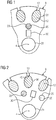
- FIG. 1 shows a layer of a magnetically conductive base body, in particular a laminated core 32 of a cage rotor 9, which shows the first to fourth recesses 28 to 31 in more detail.
- a copper conductor bar 12 is provided in the first recess 28, which is designed as a groove 33 of the cage rotor 9, which is prefabricated, inserted or inserted axially into the first recess 28. It is therefore also referred to as an insert stick.
- a groove slot 13 extends radially outward from this groove or first recess 28 to an air gap 14 of a dynamoelectric machine 1, not shown in this illustration.
- the starting behavior and torque of the squirrel-cage rotor 9 and thus of the dynamoelectric machine 1 can be set via the width and / or radial length of the slot 13. Furthermore, there are second recesses 29 through which the short-circuit ring 10 can be cast on an axial end face 46 of the cage rotor 9, for example by liquid aluminum. This second recess is then designed as a pouring channel 11.
- a third recess 30 Adjacent to this, radially inward extends a third recess 30 which, when the cage rotor 9 is in operation in the dynamoelectric machine 1, functions as an axial cooling channel 16 for air or liquid cooling of the cage rotor 9 and / or the dynamoelectric machine 1 (not shown in any more detail).
- a fourth recess 31 is designed as a shaft bore 15, into which a shaft 3 is later inserted, which is connected in a rotationally fixed manner to the metal sheets or the magnetically conductive base body of the cage rotor 9.
- the necessary flow rates of the die casting processes during manufacture and / or the cooling media during operation of the machine 1 can be specified in principle.
- FIG 2 shows a similar execution as FIG. 1 , however, the arrangement of the second and third recesses 29, 30 shown here, that is to say the pouring channel 11 and the cooling channel 16 with respect to the cross-sectional shape and / or arrangement radially and in the circumferential direction, can be designed as desired in almost any manner.
- These can be angular shapes such as triangles, rectangles or other polygons, as can rounded shapes such as circles or ellipses.
- the arrangement of the second and third recesses 29 and 30 per sheet can be provided as desired using a stamping tool.
- their execution is based on the manufacturing parameters and the desired operating behavior of the machine 1.
- the first recesses 28, viewed over the axial course, can also be provided with a bevel of half to about three groove divisions in order, inter alia, to Avoid ripple moments.
- the second 29 and / or third recess 30 can also be provided with a bevel. However, this increases the flow resistance both during the casting process and during cooling, so that the second 29 and third recesses 30 are more likely to run parallel to the axis 4, with an optionally selectable inclination of the first recesses 28.
- FIG 3 Another representation of the arrangement of the second and third recesses 29, 30 is FIG 3 refer to. It can also be seen that the invention with conductor bars 12 can also be used with closed grooves, as viewed in the circumferential direction, ie without a slot 13.
- the basic arrangement and positioning of the second and third recesses 29, 30 in a sheet metal are, inter alia, determined by mechanical and / or thermal specifications on the cage rotor 9.
- they can lie essentially on a radius, for example alternately arranged or also arranged radially one above the other.
- FIG 4 shows in a basic longitudinal section an illustration of a squirrel-cage rotor 9, the magnetic base body is made of sheet metal.
- Short-circuit rings 10 are arranged adjacent to the end faces 46 on the axial end faces 46 of the laminated core 32 of the cage rotor 9. That is, there are between the inside of the short-circuit ring 10 and the axial end faces 46 of the laminated core 32 of the cage rotor 9 no clearances 37.
- This encapsulation takes place on one side of the squirrel-cage rotor 9 using a direct die-casting method, as will be explained in more detail later, and / or via a pouring channel 11, which forms the short-circuit ring 10 present on the other end face 46 of the squirrel-cage rotor 9.
- the copper rod 12 is further adapted by one or more radial caulking along the slot, the slot shape or the slot space 33.
- Better contact surfaces are thus formed between conductor bar 12, in particular made of copper, and wall 36 of groove space 33, which improve mechanical fixation of the bar in the groove. This is advantageous at high speeds of a dynamoelectric machine 1.
- a comparatively better heat transfer from the copper rod 12 to the laminated core 32 is created. This improves the cooling of the cage rotor 9 and thus the overall operating behavior of the dynamoelectric machine 1.
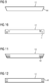
- FIG 5 shows basically the same execution as FIG 4 , only with additional cooling channels 16, which are arranged radially closer to the axis 4 compared to the pouring channels 11.
- FIG 6 shows in a basic representation an entire dynamoelectric machine 1 with a stator 7 and a winding system which forms winding heads 8 on the end faces of the stator 7.
- the stator 7 is arranged in a housing 2, which is supported on the shaft 3 via end shields 6 or the bearings 5 positioned there.
- the squirrel cage 9 is in this Case according to FIG 4 educated. But he can also according to FIG 5 or FIG 8 be trained.
- a centrifugal force-absorbing element such as e.g. a cuff 47 may be provided.
- This centrifugal force-absorbing element preferably does not protrude radially into the area of the air gap 14 in order not to impair any axial cooling through the air gap 14.
- the short-circuit rings 10 extend radially to the shaft 3. This enables additional heat dissipation from the short-circuit ring 10 into / via the shaft 3. This is particularly advantageous if the shaft 3 itself is cooled, for example by means of a lance cooling system, not shown.
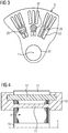
- FIG 7 shows an example of a manufacturing process, wherein the second electrically conductive material 35 in liquid form, such as aluminum, is entered via a tool 18 at an end face of the cage rotor 9 via an inlet opening 26 of the tool 18, forms a short-circuit ring 10 there and via the pouring channel 11 on the other end face 46 forms the second short-circuit ring 10 via the tool 19. Air is additionally emitted from the tools 18, 19 during the casting process via ventilation openings 27.
- the flow directions of the second electrically conductive material 35, such as aluminum, are exemplified by the arrows 21 to 25.
- Another manufacturing method only provides the tools 18, 19 on the end faces 46 of the cage rotor 9.
- the second electrically conductive material 35 (aluminum) for the respective short-circuit rings 10 is cast in simultaneously or in succession via the openings 26, 27. No pouring channels 11 are necessary.
- Another manufacturing method only provides a tool 18 on one end face of the cage rotor 9.
- a short-circuit ring 10 is thus first cast on one end face 46, then the second short-circuit ring 10 is rotated on the second end face 46 by rotating the squirrel-cage rotor 9.
- the tools 18, 19 provide the axially extending slot 13, especially on the end faces 46, with a shut-off element 40 at the transition to the area of the short-circuit ring 10 to be cast, in order to seal and keep the slot 13 free.
- FIG 8 shows a squirrel-cage rotor 9, with short-circuit rings 10, which are at a distance 37 from the end faces 46 of the laminated core. This serves, inter alia, for improved cooling, in particular of the short-circuit rings 10.
- axial cast sections 38 result between the end face of the laminated core and the short-circuit ring 10, which at least during the manufacturing process of the short-circuit rings 10 by suitable devices are bridged so that the cast material, in particular liquid aluminum, can pass from one side to the other side.
- the shape of the axial casting sections 38 is adapted to the shape of the pouring channels 11.
- the axial casting sections 38 can also be designed to be funnel-shaped axially outward in order to simplify the casting process by minimizing flow resistances during the die-casting process.
- these cast sections 38 insofar as they remain at least in part on the squirrel-cage rotor 9, can contribute to active cooling at this distance 37 between the end face 46 and the inside of the short-circuit ring 10.
- these cast sections 38 are shaped like fan blades without impairing the casting process during manufacture.
- the squirrel-cage rotors 9, the pouring channels 11 and possibly also the cast sections 38, as well as the conductors in the grooves 33 are in electrically conductive connection with the short-circuit rings 10.
- FIG 8 for example end sections of the conductor bars 12, which are formed with hole 43 and with hole 43 and slope 44, in order to increase the electrical contact areas between short-circuit ring 10 and conductor bar 12 and / or the mechanical stability between short-circuit ring 10 and conductor bar 12.
- Such squirrel-cage rotors 9 are used in asynchronous machines 1 for low and high voltage.
- the applications range from industrial drives, for example in the food and beverage industry, to traction drives, for example from rail vehicles, trucks, in particular mining trucks, and to pumps, fans and compressors.
- traction drives for example from rail vehicles, trucks, in particular mining trucks, and to pumps, fans and compressors.
- Such asynchronous machines can also be used in machine tools.
Abstract
Die Erfindung betrifft einen Käfigläufer (9) einer dynamoelektrischen Maschine (1) mit- einem magnetisch leitfähigen Grundkörper, insbesondere einem Blechpaket (32), der sich von einem axialen Ende zu einem zweiten axialen Ende entlang einer Achse (4) erstreckt, mit im wesentlich axial verlaufenden ersten Ausnehmungen (28), die als Nuten (33) ausgebildet sind und sich am radial äußeren Rand der Mantelfläche des magnetisch leitfähigen Grundkörpers befinden und die nur ein erstes Leitermaterial (34) aufweisen,- einem Kurzschlussring (10), jeweils an den axialen Enden des magnetisch leitfähigen Grundkörpers, der zumindest ein zweites elektrisch leitfähiges Material (35) aufweist und der jeweils die Achse (4) umgibt, wobei das erste elektrisch leitfähige Material (34) der Nuten (33) an den axialen Enden mit dem zweiten elektrisch leitfähigen Material (35) elektrisch kontaktiert ist.The invention relates to a squirrel - cage rotor (9) of a dynamoelectric machine (1) with a magnetically conductive base body, in particular a laminated core (32), which extends from an axial end to a second axial end along an axis (4), with essentially axially extending first recesses (28), which are designed as grooves (33) and are located on the radially outer edge of the lateral surface of the magnetically conductive base body and which have only a first conductor material (34), - a short-circuit ring (10), each on the axial ends of the magnetically conductive base body, which has at least a second electrically conductive material (35) and which in each case surrounds the axis (4), the first electrically conductive material (34) of the grooves (33) having the second electrical ends at the axial ends conductive material (35) is electrically contacted.
Description
Die Erfindung betrifft einen Käfigläufer, die Herstellung eines Käfigläufers als auch eine dynamoelektrische rotatorische Maschine mit einem derartigen Käfigläufer und die Verwendung derartiger Maschinen.The invention relates to a squirrel-cage rotor, the production of a squirrel-cage rotor and a dynamoelectric rotary machine with such a squirrel-cage rotor and the use of such machines.
Dynamoelektrische rotatorische Maschinen mit einem Käfigläufer werden als Asynchronmaschinen bezeichnet, wobei der Käfigläufer aus in Nuten eines Blechpakets angeordneten Leitern besteht, die an den jeweiligen Stirnseiten des Blechpakets jeweils durch einen Kurzschlussring elektrisch kurzgeschlossen sind.Dynamoelectric rotary machines with a squirrel-cage rotor are referred to as asynchronous machines, the squirrel-cage rotor consisting of conductors arranged in grooves in a laminated core, each of which is electrically short-circuited by a short-circuit ring on the respective end faces of the laminated core.
Bei Verwendung unterschiedlicher Leitermaterialien des Käfigläufers wird auch von Hybridläufern gesprochen, wie sie beispielsweise aus der
Die dabei beschriebenen Hybridläufer sind bezüglich ihrer elektrischen, thermischen und mechanischen Auslegung gegenüber Käfigläufern, die als reine Kupferläufer ausgeführt sind, u.a. aufgrund ihrer vergleichsweise geringeren Energieeffizienz lediglich eingeschränkt einsetzbar.In terms of their electrical, thermal and mechanical design, the hybrid runners described here are compared to cage runners that are designed as pure copper runners, among others. can only be used to a limited extent due to their comparatively lower energy efficiency.
Die unter anderem in den aufgeführten Schriften bekannte Hybrid-Rotor-Gusstechnik wurde bislang bei den Leitern so ausgeführt, dass die Nut, insbesondere der Querschnitt der Nut des Käfigläufers im Blechpaket nur teilweise von einem Kupfereinlegestab eingenommen wurde. Der verbleibende Restquerschnitt wurde als Gießkanal zur Speisung zwischen den beiden Kurzschlussringen benötigt und mit Aluminium gefüllt.The hybrid rotor casting technology known, inter alia, in the documents listed has been carried out on the conductors so that the groove, in particular the cross section of the groove of the cage rotor in the laminated core, was only partially occupied by a copper insert. The remaining cross-section was required as a pouring channel for the supply between the two short-circuit rings and was filled with aluminum.
Die elektrische Auslegung des Käfigläufers wird jedoch u.a. vom Füllgrad der Nut mit Kupfer bestimmt. Ein hoher Füllgrad ist elektrisch vorteilhaft, steht aber damit der bisher bekannten Fertigungstechnologie des Hybrid-Rotorguss entgegen. Diese erfordert einen hinreichend großen verbleibenden Querschnitt in der Nut, um das schmelzförmige Aluminium von einer Seite, der Angussseite des einen Kurzschlussringes, auf die andere Seite, die Entlüftungsseite des zweiten Kurzschlussringes zu bringen.The electrical design of the cage rotor is determined, among other things, by the degree of filling of the groove with copper. A high degree of filling is electrically advantageous, but is therefore better than that previously known Manufacturing technology of hybrid rotor casting. This requires a sufficiently large remaining cross section in the groove in order to bring the molten aluminum from one side, the sprue side of the one short-circuit ring, to the other side, the venting side of the second short-circuit ring.
Für die elektrische Auslegung der dynamoelektrischen Maschine relevant sind weiter u.a. die zum Luftspalt der Maschine gewandte Streustege der Nut, die aber durch den bisherigen Fertigungsprozess bei Hybridläufern nicht realisierbar sind, da das Blechpaket der Läufernut in Umfangsrichtung betrachtet geschlossen sein muss, um den Austritt flüssigen Aluminiums während der Fertigung zu verhindern.Relevant for the electrical design of the dynamoelectric machine include the groove's scattering ridges, which face the air gap of the machine, but which are not feasible due to the previous manufacturing process for hybrid rotors, since the laminated core of the rotor groove must be closed in the circumferential direction in order to prevent liquid aluminum from escaping during production.
Nachteilig ist des Weiteren, dass eine Entwärmung eines Leiterstabes bzw. Kurzschlussstabes lediglich durch eine punktförmige Auflage des Stabes an den Wänden der Nut stattfindet. Bei Schrumpfung des Aluminiums im Bereich der Nut führt dies außerdem zur Spaltbildung, die u.a. keine zuverlässige Entwärmung des Leitermaterials aus der Nut in das Blechpaket zulässt.A further disadvantage is that a conductor bar or short-circuit bar is only cooled by a punctiform support of the bar on the walls of the groove. If the aluminum shrinks in the area of the groove, this also leads to the formation of gaps, which does not allow reliable cooling of the conductor material from the groove in the laminated core.
Ebenso ist eine mechanische Fixierung des Stabes bzw. des Kupfereinlegers innerhalb der Nut und in der Mitte des Blechpakets aus dem oben ausgeführten Grund unbestimmt. An den Enden des Blechpakets des Kurzschlussläufers erfolgt lediglich eine Fixierung über die Kurzschlussringe. Bei vergleichsweise hohen Drehzahlen von über 10000 U/min und/oder Lastwechseln kann ein "schlackern" der Stäbe in der Nut nicht ausgeschlossen werden.A mechanical fixation of the rod or the copper insert within the groove and in the middle of the laminated core is also indefinite for the reason stated above. At the ends of the laminated core of the squirrel-cage rotor, there is only fixation via the squirrel-cage rings. At comparatively high speeds of over 10,000 rpm and / or load changes, a "slagging" of the bars in the groove cannot be ruled out.
Ausgehend davon liegt der Erfindung die Aufgabe zugrunde, einen Käfigläufer einer Asynchronmaschine zu schaffen, der die oben genannten Nachteile vermeidet. Ebenso liegt der Erfindung die Aufgabe zugrunde ein vergleichsweise wirtschaftliches Verfahren zur Herstellung eines Käfigläufers bereitzustellen. Des Weiteren soll das Anlaufverhalten dieses Läufers zuverlässig einstellbar sein.Based on this, the object of the invention is to create a squirrel-cage rotor of an asynchronous machine which avoids the disadvantages mentioned above. The invention is also based on the object of providing a comparatively economical method for producing a cage rotor. Furthermore, the starting behavior of this rotor should be reliably adjustable.
Die Lösung der gestellten Aufgabe gelingt durch einen Käfigläufer einer dynamoelektrischen Maschine mit
- einem magnetisch leitfähigen Grundkörper, insbesondere einem Blechpaket, der sich von einem axialen Ende zu einem zweiten axialen Ende entlang einer Achse erstreckt, mit im wesentlich axial verlaufenden ersten Ausnehmungen, die als Nuten ausgebildet sind und sich am radial äußeren Rand der Mantelfläche des magnetisch leitfähigen Grundkörpers befinden und die nur ein erstes Leitermaterial aufweisen,
- einem Kurzschlussring, jeweils an den axialen Enden des magnetisch leitfähigen Grundkörpers, der zumindest ein zweites elektrisch leitfähiges Material aufweist und der jeweils die Achse umgibt, wobei das erste elektrisch leitfähige Material der Nuten an den axialen Enden mit dem zweiten elektrisch leitfähigen Material elektrisch kontaktiert ist.
- a magnetically conductive base body, in particular a laminated core, which extends from an axial end to a second axial end along an axis, with essentially axially extending first recesses which are designed as grooves and on the radially outer edge of the lateral surface of the magnetically conductive base body are located and which have only a first conductor material,
- a short-circuit ring, in each case at the axial ends of the magnetically conductive base body, which has at least one second electrically conductive material and which surrounds the axis, the first electrically conductive material of the grooves being electrically contacted with the second electrically conductive material at the axial ends.
Die Lösung der gestellten Aufgabe gelingt ebenso durch ein Verfahren zur Herstellung eines Käfigläufers einer dynamoelektrischen Maschine mit
- einem magnetisch leitfähigen Grundkörper, insbesondere einem Blechpaket, der sich von einem axialen Ende zu einem zweiten axialen Ende entlang einer Achse erstreckt, mit im wesentlich axial verlaufenden ersten Ausnehmungen, die als Nuten ausgebildet sind und sich am radial äußeren Rand der Mantelfläche des magnetisch leitfähigen Grundkörpers befinden und die nur ein erstes Leitermaterial aufweisen,
- einem Kurzschlussring, jeweils an den axialen Enden des magnetisch leitfähigen Grundkörpers, der zumindest ein zweites elektrisch leitfähiges Material aufweist und der jeweils die Achse umgibt, wobei das erste elektrisch leitfähige Material der Nuten an den axialen Enden mit dem zweiten elektrisch leitfähigen Material elektrisch kontaktiert ist,
- Bereitstellen eines magnetisch leitfähigen Grundkörpers, insbesondere eines paketierten Blechpakets mit einer vorgebbaren Anzahl von zumindest drei Ausnehmungen,
- axiales Einsetzen vorgefertigter Leiterstäbe aus einem ersten elektrisch leitfähigen Material, insbesondere Kupferstäbe in die ersten Ausnehmungen des magnetisch leitfähigen Grundkörpers, die als Nuten ausgeführt sind, derart, dass an den axialen Enden des magnetisch leitfähigen Grundkörpers die Leiterstäbe aus den ersten Ausnehmungen ragen,
- Einsetzen des mit diesem ersten Material versehenen magnetisch leitfähigen Grundkörpers in eine Gießvorrichtung, derart dass ein erstes Werkzeug und ein zweites Werkzeug die jeweiligen axialen Enden zumindest abschnittsweise dicht umschließen,
- Gießen eines Füllmaterials, insbesondere eines zweiten elektrisch leitfähigen Materials über ein Werkzeug in den Bereich eines Kurzschlussrings und/oder in zweite Ausnehmungen des magnetisch leitfähigen Grundkörpers, die als Gießkanal ausgeführt sind.
- a magnetically conductive base body, in particular a laminated core, which extends from an axial end to a second axial end along an axis, with essentially axially extending first recesses which are designed as grooves and on the radially outer edge of the lateral surface of the magnetically conductive base body are located and which have only a first conductor material,
- a short-circuit ring, in each case on the axial ends of the magnetically conductive base body, which has at least one second electrically conductive material and which surrounds the axis, the first electrically conductive material of the grooves being electrically contacted with the second electrically conductive material at the axial ends,
- Providing a magnetically conductive base body, in particular a packaged laminated core with a predeterminable number of at least three recesses,
- axial insertion of prefabricated conductor bars made of a first electrically conductive material, in particular copper bars into the first recesses of the magnetically conductive base body, which are designed as grooves, such that the conductor rods protrude from the first recesses at the axial ends of the magnetically conductive base body,
- Inserting the magnetically conductive base body provided with this first material into a casting device such that a first tool and a second tool tightly enclose the respective axial ends at least in sections,
- Pouring a filling material, in particular a second electrically conductive material, via a tool into the area of a short-circuit ring and / or into second recesses in the magnetically conductive base body, which are designed as a pouring channel.
Die Lösung der gestellten Aufgabe gelingt ebenso durch ein Verfahren zur Herstellung eines Käfigläufers einer dynamoelektrischen Maschine mit
- einem magnetisch leitfähigen Grundkörper, insbesondere einem Blechpaket, der sich von einem axialen Ende zu einem zweiten axialen Ende entlang einer Achse erstreckt, mit im wesentlich axial verlaufenden ersten Ausnehmungen, die als Nuten ausgebildet sind und sich am radial äußeren Rand der Mantelfläche des magnetisch leitfähigen Grundkörpers befinden und die nur ein erstes Leitermaterial aufweisen,
- einem Kurzschlussring, jeweils an den axialen Enden des magnetisch leitfähigen Grundkörpers, der zumindest ein zweites elektrisch leitfähiges Material aufweist und der jeweils die Achse umgibt, wobei das erste elektrisch leitfähige Material der Nuten an den axialen Enden mit dem zweiten elektrisch leitfähigen Material elektrisch kontaktiert ist,
- Bereitstellen eines magnetisch leitfähigen Grundkörpers, insbesondere eines paketierten Blechpakets mit einer vorgebbaren Anzahl von zwei oder drei Ausnehmungen,
- axiales Einsetzen vorgefertigter Leiterstäbe aus einem ersten elektrisch leitfähigen Material, insbesondere Kupferstäbe in die ersten Ausnehmungen des magnetisch leitfähigen Grundkörpers, die als Nuten ausgeführt sind, derart, dass an den axialen Enden des magnetisch leitfähigen Grundkörpers die Leiterstäbe aus den ersten Ausnehmungen ragen,
- Einsetzen des mit diesem ersten Material versehenen magnetisch leitfähigen Grundkörpers in eine Gießvorrichtung, derart dass ein erstes Werkzeug und ein zweites Werkzeug die jeweiligen axialen Enden zumindest abschnittsweise dicht umschließen,
- Gießen eines Füllmaterials, insbesondere eines zweiten elektrisch leitfähigen Materials über die Werkzeuge in dem Bereich eines Kurzschlussrings zeitgleich oder hintereinander.
- a magnetically conductive base body, in particular a laminated core, which extends from an axial end to a second axial end along an axis, with essentially axially extending first recesses which are designed as grooves and on the radially outer edge of the lateral surface of the magnetically conductive base body are located and which have only a first conductor material,
- a short-circuit ring, in each case on the axial ends of the magnetically conductive base body, which has at least one second electrically conductive material and which surrounds the axis, the first electrically conductive material of the grooves being electrically contacted with the second electrically conductive material at the axial ends,
- Providing a magnetically conductive base body, in particular a packaged laminated core with a predeterminable number of two or three recesses,
- axial insertion of prefabricated conductor bars made of a first electrically conductive material, in particular copper bars into the first recesses of the magnetically conductive base body, which are designed as grooves, such that the conductor rods protrude from the first recesses at the axial ends of the magnetically conductive base body,
- Inserting the magnetically conductive base body provided with this first material into a casting device such that a first tool and a second tool tightly enclose the respective axial ends at least in sections,
- Pouring a filling material, in particular a second electrically conductive material, over the tools in the area of a short-circuit ring simultaneously or in succession.
Die Lösung der gestellten Aufgabe gelingt ebenso durch eine dynamoelektrische Maschine mit einem erfindungsgemäßen Käfigläufer hergestellt durch eines der erfindungsgemäßen Verfahren.The problem is also solved by a dynamoelectric machine with a squirrel-cage rotor according to the invention produced by one of the methods according to the invention.
Durch den erfindungsgemäßen Aufbau des Käfigläufers wird nunmehr ein Leiter aus einem ersten elektrisch leitfähigen Material in einer vorgegebenen Form, insbesondere ein Leiterstab aus Kupfer in eine erste Ausnehmung des magnetisch leitfähigen Grundkörpers, also beispielsweise einem axial paketierten Blechpaket des Käfigläufers axial eingesetzt und/oder fixiert und/oder positioniert.Due to the structure of the cage rotor according to the invention, a conductor made of a first electrically conductive material in a predetermined shape, in particular a copper conductor rod, is now axially inserted and / or fixed and / or fixed in a first recess in the magnetically conductive base body, for example an axially packaged laminated core of the cage rotor / or positioned.
In den ersten Ausnehmungen des Käfigläufers ist nur ein Leitermaterial vorgesehen. Dies ist insbesondere ein vorgefertigter Leiterstab aus Kupfer. Materialverunreinigungen des Leitermaterials oder Oxidschichten sind dabei unter dem Leitermaterial zu subsumieren.Only one conductor material is provided in the first recesses of the cage rotor. This is, in particular, a prefabricated copper conductor bar. Material contamination of the conductor material or oxide layers are to be subsumed under the conductor material.
Die erste Ausnehmung ist vorzugsweise als Nut mit einem zu einem Luftspalt der dynamoelektrischen Maschine weisenden Nutschlitz ausgeführt. Dieser Nutschlitz ist im Betrieb einer dynamoelektrischen Maschine u.a. für das Anlaufverhalten der Maschine und den Anlauf- bzw. Betriebsstrom ausschlaggebend, da durch den Nutschlitz u.a. die Streureaktanz des Läufers beeinflusst wird.The first recess is preferably designed as a groove with a groove slot facing an air gap of the dynamoelectric machine. This slot is used in the operation of a dynamoelectric machine, among other things. decisive for the start-up behavior of the machine and the start-up or operating current, as through the slot, among other things. the scattering reactivity of the runner is influenced.
Um nun auch für große Maschinen (z.B. Achshöhe > 500, Hochspannung > 1000 V, Leistungsbereich > 500 Kilowatt) einen Hybridläufer bereitstellen zu können, ohne einen aufwändigen kompletten Kupferverguss des Käfigläufers durchführen zu müssen, werden an den Stirnseiten des magnetisch leitfähigen Grundkörpers erfindungsgemäß aus einem zweiten elektrisch leitfähiges Material Kurzschlussringe angegossen, die entweder beabstandet von den Stirnseiten ausgeführt sind oder direkt an den Stirnseiten anliegen.In order to be able to provide a hybrid rotor for large machines (e.g. shaft height> 500, high voltage> 1000 V, power range> 500 kilowatts) without having to carry out complex copper casting of the squirrel-cage rotor, according to the invention, a magnet is used on the front sides of the magnetically conductive base body cast on second electrically conductive material short-circuit rings, which are either spaced from the end faces or rest directly on the end faces.
Die Kurzschlussringe werden über dafür vorgesehene Werkzeuge und ggf. weitere spezielle zweite Ausnehmungen im magnetisch leitfähigen Grundkörper des Käfigläufers gebildet, insbesondere über Gießkanäle, die ein zweites elektrisch leitfähiges Material von einer Seite des leitfähigen Grundkörpers auf die andere Seite in flüssigem Zustand transportieren.The short-circuit rings are formed by means of tools provided for this purpose and, if necessary, further special second recesses in the magnetically conductive base body of the cage rotor, in particular by means of pouring channels which transport a second electrically conductive material from one side of the conductive base body to the other side in the liquid state.
Im erstarrten Zustand dieses Füllmaterials, also dem zweiten elektrisch leitfähiges Material sind nunmehr an den axialen Stirnseiten des Käfigläufers Kurschlussringe ausgebildet. Gleichzeitig ist der Gießkanal bzw. Füllkanal, sofern vorhanden, mit dem Füllmaterial, also beispielsweise dem geschmolzenen Aluminium, das dann ausgehärtet ist, gefüllt.In the solidified state of this filler material, that is to say the second electrically conductive material, short-circuit rings are now formed on the axial end faces of the cage rotor. At the same time, the pouring channel or filling channel, if present, is filled with the filling material, for example the molten aluminum, which has then hardened.
Das erste Leitermaterial ist stangenförmig vorgefertigt. Pro erster Ausnehmung ist eine Stange vorgesehen. Es können sich aber auch in einer ersten Ausnehmung mehrere Stangen befinden die sich - im Querschnitt dieser ersten Ausnehmung betrachtet - zu diesem Querschnitt, sozusagen puzzleartig ergänzen.The first conductor material is prefabricated in the form of a bar. A rod is provided for each first recess. However, there can also be a plurality of rods in a first recess, which - viewed in cross section of this first recess - complement this cross section, so to speak, like a puzzle.
Über die radiale Tiefe und/oder Breite und/oder Form des Nutschlitzes kann nunmehr die Streureaktanz des Käfigläufers im Betrieb der dynamoelektrischen Maschine eingestellt werden, so dass darüber u.a. beispielsweise das Anlaufverhalten eines Asynchronmotors mit einem derartigen Käfigläufer einstellbar ist. Die Nut ist somit ein Nutraum, der im Wesentlichen durch das erste Leitermaterial belegt ist und - soweit vorhanden - ein Nutschlitz. Der Nutraum ist dabei durch eine Nutwandung, einen Nutgrund und sofern vorhanden einen Nutschlitz begrenzt auf.Via the radial depth and / or width and / or shape of the slot slot, the scattering reactivity of the cage rotor during operation of the dynamoelectric machine can now be set, so that, among other things, for example, the starting behavior of an asynchronous motor with such a squirrel-cage rotor can be set. The groove is thus a groove space which is essentially occupied by the first conductor material and - if present - a slot slot. The groove space is limited by a groove wall, a groove base and, if present, a groove slot.
Das erste Leitermaterial befindet sich im Nutraum und zu einem geringen Anteil ggf. noch im Nutschlitz.The first conductor material is located in the slot space and, to a small extent, may still be in the slot.
Durch den erfindungsgemäßen Herstellungsprozess mit speziellem Gießkanal oder auch ohne, ist nunmehr die Nut mit einem Streusteg ausführbar und kann somit u.a. unabhängig von einer Gestaltung des Gießkanals ausgeführt werden. Es sind somit keine Einschränkungen bezüglich des Kupferfüllfaktors einer Nut vorhanden. Der Leiterstab bzw. die Leiterstäbe einer ersten Ausnehmung entsprechen in der Querschnittsfläche und Querschnittform im Wesentlichen dem Nutraum.Due to the manufacturing process according to the invention with a special pouring channel or also without, the groove can now be carried out with a spreading web and can thus, among other things. regardless of the design of the pouring channel. There are therefore no restrictions on the copper fill factor of a groove. The cross-sectional area and cross-sectional shape of the conductor bar or the conductor bars of a first recess essentially correspond to the groove space.
Über den Nutschlitz lässt sich nun, wie bei konventionellen Kupferläufern die Anforderungen hinsichtlich der Anlaufdaten, wie Drehmoment oder Anlaufstrom ausschließlich im Rahmen der geometrischen Fertigungsbedingungen realisieren und festlegen. Die Nutschlitze sind dabei im Querschnitt betrachtet u.a. parallelflankig oder V-förmig ausgeführt. Der Nutschlitz ist normalerweise parallelflankig und/oder in der radialen Mitte der Nut ausgebildet. Der Nutschlitz kann außerdem ebenso oder stattdessen, radial betrachtet, schräg verlaufen und/oder außermittig bzgl. der radialen Mitte der Nut angeordnet sein.Via the slot, as with conventional copper rotors, the requirements with regard to the start-up data, such as torque or starting current, can only be realized and defined within the framework of the geometric manufacturing conditions. The slot slots are considered in cross-section, among others. parallel-flanked or V-shaped. The slot is usually parallel flanked and / or in the radial center of the groove. The slot slot can also or instead, viewed radially, run obliquely and / or be arranged eccentrically with respect to the radial center of the slot.
Durch ein Verstemmen des vorgefertigten Stabes, bzw. Leiterstabes bzw. Leiters in der Nut wird nunmehr eine plastische Verformung dieses Stabes in dem Nutraum herbeigeführt, was zu einem Formschluss dieses Stabes an die Wand des Nutraumes, also der Innenseite führt. Aufgrund der größeren Anlageflächen von Nutwandung und Leiterstab und der damit gegenüber einem punktuellen Kontakt gleichmäßigeren und besseren Entwärmung, wird auch ein besseres Betriebsverhalten der dynamoelektrischen Maschine erreicht.By caulking the prefabricated rod, or conductor rod or conductor in the groove, plastic deformation of this rod is now brought about in the groove space, which leads to a positive connection of this rod to the wall of the groove space, i.e. the inside. Due to the larger contact surfaces of the groove wall and conductor bar and the more uniform and better heat dissipation compared to a point contact, the dynamoelectric machine also achieves better operating behavior.
Beim Verstemmen wird dabei ein Formschluss zwischen Leiterstab und Nutwandung herbeigeführt, der beispielsweise durch Eintreiben eines Meißels in den in dem Nutraum positionierten Leiterstab mittels eines oder mehrerer Schlitze generiert wird. Der Meißel wird dabei über den Nutschlitz auf dem Leiterstab angesetzt.When caulking, a positive connection between the conductor bar and groove wall is brought about, which is generated, for example, by driving a chisel into the conductor bar positioned in the groove space by means of one or more slots. The chisel is placed over the slot on the conductor bar.
Darüber hinaus ist auch die mechanische Fixierung axial entlang des Blechpakets gegeben, was insbesondere bei höheren mechanischen Anforderungen an Drehzahl und Temperaturlastwechsel der dynamoelektrischen Maschine besonders vorteilhaft ist. Bei vergleichsweise hohen Drehzahlen von über 10000 U/min und/oder Lastwechseln wird somit ein "schlackern" der Leiterstäbe in der Nut vermieden.In addition, there is also a mechanical fixation axially along the laminated core, which is particularly advantageous in the case of higher mechanical demands on the speed and temperature load changes of the dynamoelectric machine. At comparatively high speeds of more than 10,000 rpm and / or load changes, "slipping" of the conductor bars in the groove is thus avoided.
Als Alternative oder Ergänzung zum Verstemmen des Leiterstabs in der ersten Ausnehmung eignet sich für geschlossene Nuten und Nuten mit Nutschlitz auch eine Aufheizung des magnetisch leitfähigen Grundkörpers, also des Blechpakets. Dies führt zu einer Aufweitung der ersten Ausnehmungen, also der Nuten, was das axiale Einsetzen der Leiterstäbe in diese Nut erleichtert. Durch die anschließende Abkühlung und den dadurch herbeigeführten Schrumpfprozess werden die Leiterstäbe in den ersten Ausnehmungen fixiert, was ebenfalls zu einem Formschluss zwischen Nutwandung und jeweiligen Leiterstäben führt.As an alternative or supplement to caulking the conductor rod in the first recess, heating the magnetically conductive base body, that is to say the laminated core, is also suitable for closed slots and slots with a slot slot. This leads to an expansion of the first recesses, that is to say the grooves, which facilitates the axial insertion of the conductor bars into this groove. As a result of the subsequent cooling and the resulting shrinking process, the conductor bars are fixed in the first recesses, which likewise leads to a positive connection between the groove wall and the respective conductor bars.
Im weiteren Herstellungsprozess kann diese Aufheizung des magnetisch leitfähigen Grundkörpers, also des Blechpakets für den Gießprozess vorteilhaft sein, da sich durch die Aufheizung, das durch den Gießkanal zu führende zweite elektrisch leitfähige Material, weniger schnell abkühlt.In the further manufacturing process, this heating of the magnetically conductive base body, that is to say the laminated core, can be advantageous for the casting process, since the heating, the second electrically conductive material to be led through the pouring channel cools less quickly.
Die weiteren Ausnehmungen im Käfigläufer, die im wesentlichen achsparallel verlaufen, wie die zweiten, dritten und vierten Ausnehmungen sind in Umfangsrichtung betrachtet geschlossen ausgeführt. Die vierte Ausnehmung ist dabei eine Wellenbohrung, in die nach Fertigstellen des Käfigläufers eine Welle drehfest positioniert werden kann.The further recesses in the squirrel-cage rotor, which run essentially axially parallel, like the second, third and fourth recesses, are designed to be closed when viewed in the circumferential direction. The fourth recess is a shaft bore into which a shaft can be positioned in a rotationally fixed manner after the cage rotor has been completed.
Die dritten Ausnehmungen, die um die Achse nahezu beliebig verteilt werden können, bilden axial verlaufende Kühlkanäle, die optional an einen Kühlkreislauf der dynamoelektrischen Maschine anschließbar sind. Die zweiten Ausnehmungen sind insbesondere Gießkanäle, über die das Füllmaterial, das zweite elektrisch leitfähige Material von einem axialen Ende zum anderen axialen Ende des Käfigläufers im Herstellungsprozess gelangt. Dies ist vor allem flüssiges Aluminium.The third recesses, which can be distributed almost arbitrarily around the axis, form axially extending cooling channels, which can optionally be connected to a cooling circuit of the dynamoelectric machine. The second recesses are, in particular, pouring channels through which the filling material, the second electrically conductive material, passes from one axial end to the other axial end of the cage rotor in the manufacturing process. This is primarily liquid aluminum.
Die elektrische Leitfähigkeit des ersten Leitermaterials und des zweiten elektrisch leitfähigen Materials sind unterschiedlich. Ebenso sind deren Schmelztemperaturen unterschiedlich, so dass das Material mit niedrigerem Schmelzpunkt gegossen wird. Vorteilhafterweise ist dabei das erste Leitermaterial aus Kupfer, vorzugsweise vorgefertigte Kupferstäbe und das zweite elektrisch leitfähige Material ist Aluminium.The electrical conductivity of the first conductor material and the second electrically conductive material are different. Their melting temperatures are also different, so that the material with a lower melting point is cast. The first conductor material is advantageously made of copper, preferably prefabricated copper rods, and the second electrically conductive material is aluminum.
Der erfindungsgemäße Käfigläufer benötigt für seine Fertigung auf jeden Fall erste Ausnehmungen und eine vierte Ausnehmung, die zweiten und dritten Ausnehmungen sind optional und werden u.a. nach Herstellungsart, Einsatzort und/oder Betriebszyklen der dynamoelektrischen Maschine sowohl in ihrer Form, in ihrer Anzahl, als auch in ihrer radialen Anordnung innerhalb des Käfigläufers festgelegt.The squirrel-cage rotor according to the invention definitely requires first recesses and a fourth recess for its production, the second and third recesses are optional and are used, among other things. according to the type of manufacture, place of use and / or operating cycles of the dynamoelectric machine, both in terms of their shape, number and radial arrangement within the cage rotor.
Der Herstellungsprozess eines derartigen Käfigläufers kann von einer Seite, also von einem axialen Ende des Käfigläufers zum anderen erfolgen, in dem das zweite elektrisch leitfähige Material, also z.B. flüssiges Aluminium in einen Füllraum eines ersten Werkzeugs eintritt und von dort über die Gießkanäle sich axial an das andere axiale Ende des Käfigläufers ergießt und dort den zweiten Kurzschlussring bildet.The manufacturing process of such a squirrel-cage rotor can take place from one side, that is to say from one axial end of the squirrel-cage rotor to the other, in which the second is electrically conductive Material, for example liquid aluminum, enters a filling space of a first tool and from there pours axially over the pouring channels to the other axial end of the cage rotor and forms the second short-circuit ring there.
Eine andere Möglichkeit einen derartigen Käfigläufer zu gestalten, besteht darin, nachdem die Leiterstäbe in die Nut eingelegt und/oder fixiert worden sind, nur an den axialen Enden des Käfigläufers die Kurzschlussringe gleichzeitig oder nacheinander anzugießen.Another possibility of designing such a squirrel-cage rotor is, after the conductor bars have been inserted and / or fixed in the groove, to cast the short-circuit rings simultaneously or in succession only at the axial ends of the squirrel-cage rotor.
Die Kurzschlussringe werden dabei also separat mittels geeigneten Werkzeugen bzw. Vorrichtungen gleichzeitig oder hintereinander gegossen, ohne dass Gießkanäle im magnetisch leitfähigen Grundkörper notwendig sind.The short-circuit rings are thus cast separately or in succession using suitable tools or devices, without the need for casting channels in the magnetically conductive base body.
Die Werkzeuge bzw. Gießvorrichtungen werden dabei beispielsweise mit flüssigem Aluminium gefüllt, wobei eine elektrische Kontaktierung der unterschiedlichen Materialien von Kurzschlussring und den Leiterstäben, insbesondere den aus dem magnetisch leitfähigen Grundkörper ragenden vorgegebenen Abschnitten herbeigeführt wird.The tools or casting devices are filled, for example, with liquid aluminum, whereby the different materials of the short-circuit ring and the conductor bars, in particular the predetermined sections protruding from the magnetically conductive base body, are brought into electrical contact.
Schrägung der Achse oder leichte Pendelungen um die Achse des magnetisch leitfähigen Grundkörpers, beispielsweise Blechpaket unterstützt während des Gießprozesses eine Endgasung, sodass eine Lunckerbildung unterdrückt wird.Slanting of the axis or slight oscillations around the axis of the magnetically conductive base body, for example a laminated core, supports final gassing during the casting process, so that the formation of lunches is suppressed.
Des Weiteren kann die elektrische und/oder mechanische Verbindung zwischen den Leiterstäben und den Kurzschlussringen dadurch verbessert werden kann, dass die unterschiedlichen Materialien von Leiterstab und Kurzschlussring, insbesondere an deren vorgebbaren Kontaktstellen eine mischkristalline Verbindung eingehen.Furthermore, the electrical and / or mechanical connection between the conductor bars and the short-circuit rings can be improved in that the different materials of the conductor bar and short-circuit ring enter into a mixed-crystalline connection, in particular at their predeterminable contact points.
Die Leiterstäbe ragen an beiden stirnseitigen Enden des Blechpakets des Läufers axial aus diesem heraus und in die angegossenen Kurzschlussringe. Die Erhöhung der Bindungskräfte an den Kontaktstellen, also zwischen den Leiterenden und Kurzschlussringen wird beispielsweise dadurch erreicht, dass die Leiter derartig beschichtet werden, dass sowohl zwischen der Beschichtung und den Leitern eine Legierung - also eine mischkristalline Verbindung - entsteht, als auch zwischen der Beschichtung und den gegossenen Kurzschlussringe.The conductor bars protrude axially from both ends of the laminated core of the rotor and into the cast-on short-circuit rings. The increase in binding forces At the contact points, i.e. between the conductor ends and short-circuit rings, this is achieved, for example, by coating the conductors in such a way that an alloy - i.e. a mixed-crystalline connection - is formed between the coating and the conductors, as well as between the coating and the cast short-circuit rings.
Bei einer Erwärmung des Käfigläufers im Betrieb der dynamoelektrischen Maschine werden Temperaturen von ca. 150°C erreicht. Hierdurch kann der Übergang zwischen den Leiterstäben und den Kurzschlussringen hochohmiger werden, wodurch es zu einer Verschlechterung des elektrischen Leitwertes im Bereich des Übergangs zwischen den Kurzschlussringen und den Leiterstäben kommt. Das im Druckgussverfahren aus Abdichtungsgründen u.a. axial zusammengepresste Läuferblechpaket kann sich axial wieder aufweiten, wenn die Verbindung zwischen den Leiterstäben und den gegossenen Kurzschlussringen keine ausreichende axiale Haltekraft aufbringen kann.When the cage rotor heats up during operation of the dynamoelectric machine, temperatures of approximately 150 ° C. are reached. As a result, the transition between the conductor bars and the short-circuit rings can become high-resistance, which leads to a deterioration in the electrical conductivity in the region of the transition between the short-circuit rings and the conductor bars. The die casting process for sealing reasons, among other things. Axially compressed rotor laminated core can expand again axially if the connection between the conductor bars and the cast short-circuit rings cannot apply sufficient axial holding force.
Durch die Beschichtung werden die Leiterstäbe durch maximal mögliche Bindungskräfte an den Druckguss im Kurzschlussring gebunden. Entsprechend bleibt die Verbindung zwischen den Leiterstäben und den Kurzschlussringen trotz unterschiedlicher thermischer Ausdehnungskoeffizienten der unterschiedlichen Materialien in axialer und radialer Richtung auch dann stabil, wenn der Käfigläufer im Betrieb der dynamoelektrischen Maschine ausgeprägte thermische Zyklen durchfährt.Due to the coating, the conductor bars are bound to the die casting in the short-circuit ring by the maximum possible binding forces. Accordingly, the connection between the conductor bars and the short-circuit rings remains stable in spite of different thermal expansion coefficients of the different materials in the axial and radial directions even when the squirrel-cage rotor undergoes pronounced thermal cycles during operation of the dynamoelectric machine.
Im Betrieb der dynamoelektrischen Maschine verursachen bei hohen Drehzahlen auch die auf den Läufer wirkenden Fliehkräfte teils heftige mechanische Spannungen in dem Leiter-Kurschlussring.During operation of the dynamo-electric machine, the centrifugal forces acting on the rotor also cause violent mechanical stresses in the conductor short-circuit ring at high speeds.
Weiterhin kann durch diese Legierung ein optimaler elektrischer Übergangsleitwert zwischen den Materialien von Kurzschlussring und Leiterstab geschaffen werden.This alloy can also be used to create an optimal electrical transition conductance between the materials of the short-circuit ring and conductor bar.
Die erste Legierungsschicht wird beispielsweise durch elektromechanisches Galvanisieren erzeugt. Hierbei wird zunächst auf elektrochemischem Wege eine Schicht des Beschichtungsmaterials, insbesondere auf vorgegebenen Abschnitten der Leiter, insbesondere den Leiterstäben abgeschieden. Zwischen dem Leiter und dem Beschichtungsmaterial entsteht bei diesem Prozess die gewünschte mischkristalline Verbindung. Durch den Druckgussprozess schmilzt diese Beschichtung auf den Leitern auf und geht mit der Druckschmelze ebenfalls eine mischkristalline Verbindung ein, so dass eine zweite Legierungsschicht entsteht.The first alloy layer is produced, for example, by electromechanical electroplating. In this case, a layer of the coating material is first deposited electrochemically, in particular on predetermined sections of the conductors, in particular the conductor bars. In this process, the desired mixed crystalline connection is created between the conductor and the coating material. Due to the die-casting process, this coating melts on the conductors and also forms a mixed-crystalline compound with the pressure melt, so that a second alloy layer is created.
Anstelle des Galvanisierens sind andere Beschichtungsverfahren denkbar, die ebenso zu den gewünschten mischkristallinen Verbindungen zwischen den unterschiedlichen Materialien führen.Instead of electroplating, other coating processes are conceivable, which likewise lead to the desired mixed-crystalline connections between the different materials.
So ist eine Ausführungsform vorteilhaft, bei der die Beschichtung und die erste Legierungsschicht durch ein thermisches Spritzverfahren, insbesondere Flammspritzen, Plasmaspritzen, Lichtbogenspritzen oder Laserspritzen, erzeugt werden.An embodiment is advantageous in which the coating and the first alloy layer are produced by a thermal spraying process, in particular flame spraying, plasma spraying, arc spraying or laser spraying.
Bei einer Alternative hierzu werden die Beschichtung und die erste Legierungsschicht durch Kaltgasspritzverfahren erzeugt.In an alternative to this, the coating and the first alloy layer are produced by cold gas spraying.
Bei einer weiteren Alternative wird die Beschichtung und die erste Legierungsschicht durch Aufdampfen erzeugt werden.In a further alternative, the coating and the first alloy layer are produced by vapor deposition.
Bei den erfindungsgemäßen Herstellverfahren, insbesondere aber auch beim Galvanisieren wird vorteilhafterweise vor dem Beschichten eine Oxidschicht von den Leitern durch chemische Vorbehandlung der Leiter entfernt. Eine Oxidschicht hat isolierende elektrische Eigenschaften, so dass durch das Entfernen besagter Oxidschicht der Übergangswiderstand zwischen dem ersten und dem zweiten Material deutlich reduziert wird.In the production methods according to the invention, but in particular also in electroplating, an oxide layer is advantageously removed from the conductors by chemical pretreatment of the conductors before coating. An oxide layer has insulating electrical properties, so that the contact resistance between the first and the second material is significantly reduced by removing said oxide layer.
Insbesondere im Bereich der Enden der Leiterstäbe, insbesondere Kupferstäbe, die aus dem Läuferblechpaket heraus und in die Kurzschlussringe ragen, entsteht eine äußerst stabile Verbindung zwischen den beiden Materialien, so dass die Festigkeit bezüglich thermischer Zyklen und im Betrieb auftretenden Fliehkräften erhöht wird, ohne die elektrische Leitfähigkeit insbesondere an den Übergangsstellen also den Kontaktstellen zu reduzieren. Hierbei entsteht somit eine nahezu ideale elektrische und mechanische Verbindung zwischen den Kurzschlussringen aus dem zweiten elektrische leitfähigen Material beispielsweise Aluminium und den Leitern, beispielsweise Kupferstäben.Particularly in the area of the ends of the conductor bars, in particular copper bars, which protrude from the rotor laminated core and into the short-circuit rings, an extremely stable connection is created between the two materials, so that the strength with regard to thermal cycles and centrifugal forces occurring during operation is increased without the electrical To reduce conductivity, in particular at the transition points, the contact points. This creates an almost ideal electrical and mechanical connection between the short-circuit rings made of the second electrically conductive material, for example aluminum, and the conductors, for example copper rods.
Die besagten Endbereiche der Leiterstäbe stellen die kritische Verbindungsstelle zwischen den Leitern und den Kurzschlussringen dar. Entsprechend ist hier die starke kristalline Verbindung besonders wichtig. Auch ist vor allem in diesem Endbereich jedes Leiters dem elektrischen Übergangsleitwert zwischen den beiden Materialien eine besondere Bedeutung zuzumessen, da hier der Stromfluss von den Leitern auf die Kurzschlussringe übergeht.The said end regions of the conductor bars represent the critical connection point between the conductors and the short-circuit rings. Accordingly, the strong crystalline connection is particularly important here. Especially in this end area of each conductor, the electrical transition conductance between the two materials is of particular importance because the current flow from the conductors to the short-circuit rings.
Die Verbindung zwischen den Leitern und den Kurzschlussringen kann in weiterer vorteilhafter Ausgestaltung der Erfindung dadurch alternativ oder ergänzend verstärkt werden, indem die Leiter an beiden Enden jeweils einen aus dem Läuferblechpaket heraus und in die Kurzschlussringe hereinragenden Endbereich mit Formschlussmitteln zur Erzeugung eines Formschlusses zwischen den Leitern und den gegossenen Kurzschlussringen aufweisen.In a further advantageous embodiment of the invention, the connection between the conductors and the short-circuit rings can be strengthened alternatively or additionally by the conductors at both ends having an end region protruding from the rotor laminated core and into the short-circuit rings with positive-locking means for producing a positive connection between the conductors and have the cast short-circuit rings.
Durch diese Formschlussmittel in den Endbereichen der Leiter wird die Verbindung zwischen den Leiterstäben und den Kurzschlussringen weiter gestärkt. Die an den Enden herausragenden Leiter sind durch die Formschlussmittel mit den Kurzschlussringen axial verspannt. Damit werden die Leiter je nach Temperatur und je nach Wärmeausdehnungskoeffizienten der Leiter und der Kurzschlussringe auf Zug oder Druck beansprucht. Der Kurzschlussläufer ist hierbei so auszulegen, dass die Beanspruchung stets im elastischen Bereich bleibt.These form-locking means in the end regions of the conductors further strengthen the connection between the conductor bars and the short-circuit rings. The conductors protruding at the ends are axially braced by the form-locking means with the short-circuit rings. Depending on the temperature and the thermal expansion coefficient of the conductors and the short-circuit rings, the conductors are subjected to tensile or compressive stress. The squirrel-cage rotor must be designed so that the stress always remains in the elastic range.
Durch die verwendeten Formschlussmittel wird ein Verschieben der Leiter innerhalb der Kurzschlussringe oder ein Herausziehen der Leiterstäbe aus den Kurzschlussringen verhindert, wodurch ein Abriss an der Fügestelle bzw. an den Kontaktflächen zwischen den beiden Materialien vermieden werden kann.The form-locking means used prevent the conductors from shifting within the short-circuit rings or pulling the conductor bars out of the short-circuit rings, as a result of which a tear at the joint or at the contact surfaces between the two materials can be avoided.
Als Formschlussmittel sind beispielsweise Durchgangslöcher in den Endbereichen der Leiterstäbe vorstellbar, die von der Schmelze während des Gussprozesses ausgefüllt werden.For example, through-holes in the end regions of the conductor bars, which are filled by the melt during the casting process, are conceivable as form-locking means.
Anstelle eines Durchgangslochs sind als Formschlussmittel auch Aussparungen in den Endbereichen, Verjüngungen der Leiterstäbe innerhalb der Endbereiche, Kerben, Einschnitte, Rändelungen der Endbereiche, Verwindungen der Leiter in den Endbereichen, eine Aufspaltung der Leiter in den Endbereichen vorstellbar oder allgemein, die Kontaktflächen zwischen Leiterstab und Kurzschlussring vergrößernde Strukturen geeignet.Instead of a through hole, recesses in the end regions, tapering of the conductor bars within the end regions, notches, incisions, knurling of the end regions, twisting of the conductors in the end regions, splitting of the conductors in the end regions or generally, the contact surfaces between the conductor rod and Short-circuit ring enlarging structures are suitable.
Um die axiale Montage der Leiterstäbe in die Nut, insbesondere den Nutraum zu erleichtern, weist zumindest ein Endbereich eines Leiterstabes keine größeren Querschnittsflächen und -form als der Leiterstab selbst auf.In order to facilitate the axial assembly of the conductor bars in the groove, in particular the groove space, at least one end region of a conductor bar has no larger cross-sectional areas and shape than the conductor bar itself.
Um die Fliehkraftbeanspruchungen zu reduzieren können die Kurzschussringe an ihrem radial äußeren Rand Mittel zur Fliehkraftaufnahme vorsehen, wie z.B. eine Manschette oder einen Ring aus hochfestem Material.In order to reduce the centrifugal stresses, the short-shot rings can provide means for absorbing centrifugal force on their radially outer edge, e.g. a cuff or ring made of high-strength material.
In dem für den Kurzschlussring vorgesehenen Raum, der durch die Werkzeuge vorgegebene ist, können elektrisch leitfähige Einlegeteile positioniert werden, die dann mit eingegossen werden. Dies reduziert den Gießaufwand und/oder die Gießkanäle können dementsprechend geringer dimensioniert werden. Diese Einlegeteile können, wie oben beschrieben, beschichtet sein und/oder sind aus dem ersten Leitermaterial oder dem zweiten elektrisch leitfähigen Material oder einem weiteren elektrisch leitfähigen Material.In the space provided for the short-circuit ring, which is predetermined by the tools, electrically conductive inserts can be positioned, which are then cast in. This reduces the casting effort and / or the pouring channels can accordingly be dimensioned smaller. These inserts can, as described above, be coated and / or are made of the first conductor material or second electrically conductive material or another electrically conductive material.
Die Erfindung sowie weitere vorteilhafte Ausgestaltungen der Erfindung werden anhand beispielhaft dargestellter Ausführungsbeispiele näher erläutert. Darin zeigen:
- FIG 1 bis 3
- Blechschnitte eines Käfigläufers,
- FIG 4 und 5
- Teillängsschnitte eines Käfigläufers,
- FIG 6
- einen Teilquerschnitt einer elektrischen Maschine,
- FIG 7
- eine prinzipielle Darstellung der Herstellung eines Käfigläufers,
- FIG 8
- Teillängsschnitt eines Käfigläufers mit beabstandetem Kurzschlussring,
- FIG 9
bis 12 - Gestaltungen von Endabschnitten der Leiterstäbe.
- 1 to 3
- Sheet metal cuts of a squirrel cage,
- 4 and 5
- Partial longitudinal sections of a squirrel cage,
- FIG 6
- a partial cross section of an electrical machine,
- FIG 7
- a basic representation of the manufacture of a squirrel cage,
- FIG 8
- Partial longitudinal section of a squirrel-cage rotor with spaced short-circuit ring,
- 9 to 12
- Designs of end sections of the conductor bars.
Über Breite und/oder radiale Länge des Nutschlitzes 13 lassen sich Anlaufverhalten und Drehmoment des Käfigläufers 9 und damit der dynamoelektrischen Maschine 1 einstellen. Des Weiteren gibt es zweite Ausnehmungen 29 über die der Kurzschlussring 10 auf einer axialen Stirnseite 46 des Käfigläufers 9 beispielsweise durch flüssiges Aluminium gegossen werden kann. Diese zweite Ausnehmung ist dann als Gießkanal 11 ausgeführt.The starting behavior and torque of the squirrel-
Daran anschließend, radial nach innen erstreckt sich eine dritte Ausnehmung 30, die im Betrieb des Käfigläufers 9 in der dynamoelektrischen Maschine 1 als axialer Kühlkanal 16 für eine nicht näher dargestellte Luft- oder Flüssigkeitskühlung des Käfigläufers 9 und/oder der dynamoelektrischen Maschine 1 fungiert.Adjacent to this, radially inward extends a
Eine vierte Ausnehmung 31 ist in diesem Fall als Wellenbohrung 15 ausgeführt, in die später eine Welle 3 eingesetzt ist, die drehfest mit den Blechen bzw. dem magnetisch leitfähigen Grundkörper des Käfigläufers 9 verbunden wird.In this case, a
Über die Festlegung der Durchmesser der zweiten und dritten Ausnehmungen 29, 30 lassen sich grundsätzlich die notwendigen Durchflussmengen der Druckgießprozesse bei der Herstellung und/oder der Kühlmedien im Betrieb der Maschine 1 vorgeben.By determining the diameters of the second and
Mit anderen Worten, die Anordnung der zweiten und dritten Ausnehmung 29 und 30 pro Blech kann mit einem Stanzwerkzeug beliebig vorgesehen werden. Letztendlich orientiert sich deren Ausführung an den Herstellungsparametern und dem angestrebten Betriebsverhalten der Maschine 1. Ebenso ist auf die Wuchtung des Käfigläufers 9 zu achten, die aber auch durch Materialanhäufungen (z.B. während des Gießprozesses) bzw. Materialentnahmen (nachträgliches Bearbeiten) am Kurzschlussring 10 justiert werden kann.In other words, the arrangement of the second and
Durch axiale Anordnung derartiger Bleche, also in einem Blechpaket 32 muss sich in axialer Richtung zumindest ein im wesentlicher axialer Verlauf der Nuten und ein axialer Verlauf der Wellenbohrung 15 einstellen. Je nach Ausführung und Herstellungsart des Käfigläufers 9 können sich zusätzlich Gießkanäle 11 und/oder Kühlkanäle 16 ergeben bzw. vorgesehen werden.By axially arranging such metal sheets, that is to say in a laminated core 32, at least one essentially axial course of the grooves and one axial course must be in the axial direction adjust the shaft bore 15. Depending on the design and type of manufacture of the squirrel-
Die ersten Ausnehmungen 28 können über den axialen Verlauf betrachtet auch mit einer Schrägung von einer halben bis ca. drei Nutteilungen versehen sein, um u.a. Rippelmomente zu vermeiden. Zusätzlich kann auch die zweite 29 und/oder dritte Ausnehmung 30 mit einer Schrägung versehen sein. Dies erhöht jedoch den Strömungswiderstand sowohl beim Gießprozess als auch bei einer Kühlung, so dass die zweiten 29 und dritten Ausnehmungen 30 eher parallel zur Achse 4 verlaufen werden, bei einer optional wählbaren Schrägung der ersten Ausnehmungen 28.The first recesses 28, viewed over the axial course, can also be provided with a bevel of half to about three groove divisions in order, inter alia, to Avoid ripple moments. In addition, the second 29 and / or
Eine weitere Darstellung der Anordnung von zweiter und dritter Ausnehmung 29, 30 ist
Die grundsätzliche Anordnung und Positionierung der zweiten und dritten Ausnehmungen 29, 30 in einem Blech werden u.a. durch mechanische und/oder thermische Vorgaben an den Käfigläufer 9 festgelegt.The basic arrangement and positioning of the second and
Sie können dabei im Wesentlichen auf einem Radius liegen beispielsweise alternierend angeordnet sein oder auch radial übereinander angeordnet sein.In this case, they can lie essentially on a radius, for example alternately arranged or also arranged radially one above the other.
In den Nuten, die im Wesentlichen axial verlaufen, befindet sich in dieser Darstellung ein Kupferstab 12, der axial über die Enden des Käfigläufers 9 ragt. Diese axialen Überstände des Kupferstabs 12 sind mit Aluminium im Bereich des Kurzschlussrings 10 umgossen.In this illustration, in the grooves, which run essentially axially, there is a
Dieses Umgießen erfolgt auf der einen Seite des Käfigläufers 9 mit einem direkten Druckgussverfahren, wie dies später noch näher ausgeführt wird, und/oder über einen Gießkanal 11, der den auf der anderen Stirnseite 46 des Käfigläufers 9 vorhandenen Kurzschlussring 10 bildet.This encapsulation takes place on one side of the squirrel-
Der Kupferstab 12 wird, sofern ein Nutschlitz 13 vorhanden ist, durch ein oder mehrmaliges radiales Verstemmen entlang der Nut, der Nutform bzw. dem Nutraum 33 weiter angepasst. Damit werden bessere Anlageflächen zwischen Leiterstab 12, insbesondere aus Kupfer und der Wand 36 des Nutraumes 33 gebildet, die eine mechanische Fixierung des Stabes in der Nut verbessern. Dies ist bei hohen Drehzahlen einer dynamoelektrischen Maschine 1 vorteilhaft. Ebenso wird ein vergleichsweise besserer Wärmeübergang vom Kupferstab 12 zum Blechpaket 32 geschaffen. Damit wird die Kühlung des Käfigläufers 9 und damit das gesamte Betriebsverhalten der dynamoelektrischen Maschine 1 verbessert.If a
Um für noch höhere Drehzahlen geeignet zu sein, kann am radial äußeren Rand des Kurzschlussringe 10 zumindest auf einem axialen Abschnitt ein fliehkraftaufnehmendes Element, wie z.B. eine Manschette 47 vorgesehen werden. Dieses fliehkraftaufnehmende Element ragt dabei vorzugsweise radial nicht in den Bereich des Luftspaltes 14, um eine ev. axiale Kühlung durch den Luftspalt 14 nicht zu beeinträchtigen.In order to be suitable for even higher speeds, a centrifugal force-absorbing element, such as e.g. a
Des Weiteren können sich vor allem bei einer Ausbildung des Käfigläufers 9 nach
Ein anderes Herstellungsverfahren sieht lediglich an den Stirnseiten 46 des Käfigläufers 9 die Werkzeuge 18, 19 vor. Es wird jeweils über die Öffnungen 26, 27 das zweite elektrisch leitende Material 35 (Aluminium) für die jeweiligen Kurzschlussringe 10 zeitgleich oder hintereinander eingegossen. Es sind keine Gießkanäle 11 notwendig.Another manufacturing method only provides the
Ein anderes Herstellungsverfahren sieht lediglich an einer Stirnseite des Käfigläufers 9 ein Werkzeug 18 vor. Es wird somit zuerst ein Kurzschlussring 10 auf der einen Stirnseite 46 angegossen, danach durch Drehung des Käfigläufers 9 der zweite Kurzschlussring 10 an der zweiten Stirnseite 46.Another manufacturing method only provides a
Entscheidend bei den Gießvorgängen ist, dass die Werkzeuge 18, 19 den axial verlaufenden Nutschlitz 13, vor allem an den Stirnseiten 46 bei Übergang in den Bereich des zu gießenden Kurzschlussrings 10 ein Absperrelement 40 vorsehen, um abzudichten und den Nutschlitz 13 frei zu halten.It is crucial in the casting processes that the
Die axialen Gussabschnitt 38 können aber ebenso, wie zeichnerisch angedeutet, axial nach außen trichterförmig ausgebildet sein, um den Gießprozess zu vereinfachen, indem Strömungswiderstände während des Druckgießprozesses minimiert werden.However, as indicated in the drawing, the
Ebenso können diese Gussabschnitte 38, sofern sie zumindest zum Teil am Käfigläufer 9 verbleiben, zur aktiven Kühlung in diesem Abstand 37 zwischen Stirnseite 46 und Innenseite des Kurzschlussrings 10 beitragen. Vorteilhafterweise werden dabei diese Gussabschnitte 38 lüfterflügelähnlich ausgeformt, ohne den Gussprozess während der Herstellung zu beeinträchtigen.Likewise, these
Diese Gussabschnitte 38 können nach dem Herstellungsprozess am Käfigläufer 9 verbleiben, wobei dadurch der Abstand 37 zwischen Stirnseite 46 und Innenseite des Kurzschlussrings 10 überbrückt ist.These cast
Damit stehen die Käfigläufer 9, die Gießkanäle 11 und ggf. weiterhin Gussabschnitte 38 aufweisen, ebenso wie die Leiter in den Nuten 33 mit den Kurzschlussringen 10 in elektrisch leitender Verbindung.Thus, the squirrel-
Des Weiteren zeigt
Dies sind beispielsweise Einschnitte 41, Rändelungen 42 oder Schrägungen 44 an den Endabschnitten der Leiterstäbe 12, die in dem Kurzschlussring 10 positioniert sind.These are, for example,
Derartige Käfigläufer 9, werden bei Asynchronmaschinen 1 für Nieder- und Hochspannung eingesetzt. Die Anwendungen erstrecken sich dabei von industriellen Antrieben, beispielsweise in der Nahrungs- und Genussmittelindustrie, zu Traktionsantrieben beispielsweise von Schienenfahrzeugen, Trucks, insbesondere Miningtrucks, und zu Pumpen, Lüftern und Kompressoren. Ebenso lassen sich derartige Asynchronmaschinen bei Werkzeugmaschinen einsetzen.Such squirrel-
Der erfindungsgemäße Gedanke kann selbstverständlich auch für Linearantriebe beispielsweise in den oben aufgeführten Anwendungen umgesetzt werden.The idea of the invention can of course also be implemented for linear drives, for example in the applications listed above.
Claims (12)
Priority Applications (1)
| Application Number | Priority Date | Filing Date | Title |
|---|---|---|---|
| EP18196050.1A EP3627661B1 (en) | 2018-09-21 | 2018-09-21 | Cage rotor and manufacture of a cage rotor |
Applications Claiming Priority (1)
| Application Number | Priority Date | Filing Date | Title |
|---|---|---|---|
| EP18196050.1A EP3627661B1 (en) | 2018-09-21 | 2018-09-21 | Cage rotor and manufacture of a cage rotor |
Publications (2)
| Publication Number | Publication Date |
|---|---|
| EP3627661A1 true EP3627661A1 (en) | 2020-03-25 |
| EP3627661B1 EP3627661B1 (en) | 2021-06-02 |
Family
ID=63678530
Family Applications (1)
| Application Number | Title | Priority Date | Filing Date |
|---|---|---|---|
| EP18196050.1A Active EP3627661B1 (en) | 2018-09-21 | 2018-09-21 | Cage rotor and manufacture of a cage rotor |
Country Status (1)
| Country | Link |
|---|---|
| EP (1) | EP3627661B1 (en) |
Citations (8)
| Publication number | Priority date | Publication date | Assignee | Title |
|---|---|---|---|---|
| US6092277A (en) * | 1999-04-28 | 2000-07-25 | General Electric Company | Rotor bar swaging process |
| EP2282396A1 (en) | 2009-08-03 | 2011-02-09 | Siemens Aktiengesellschaft | Production method for a rotor with skewed squirrel-cage and rotor with skewed squirrel-cage |
| EP2299565A1 (en) * | 2009-09-17 | 2011-03-23 | Siemens Aktiengesellschaft | Cooled rotor of an asynchronous machine |
| WO2012041943A2 (en) * | 2010-09-30 | 2012-04-05 | Siemens Aktiengesellschaft | Squirrel-cage rotor |
| EP2549630A1 (en) * | 2011-07-22 | 2013-01-23 | Siemens Aktiengesellschaft | Short circuit rotor of an asynchronous engine and method for producing such a rotor |
| EP2744089A1 (en) * | 2012-12-14 | 2014-06-18 | Siemens Aktiengesellschaft | Reliable cage rotor |
| EP2953245A1 (en) * | 2014-06-02 | 2015-12-09 | Siemens Aktiengesellschaft | Cage rotor for an asynchronous motor |
| EP2891234B1 (en) | 2012-10-30 | 2016-12-14 | Siemens Aktiengesellschaft | Cage rotor and rod with an incision |
-
2018
- 2018-09-21 EP EP18196050.1A patent/EP3627661B1/en active Active
Patent Citations (9)
| Publication number | Priority date | Publication date | Assignee | Title |
|---|---|---|---|---|
| US6092277A (en) * | 1999-04-28 | 2000-07-25 | General Electric Company | Rotor bar swaging process |
| EP2282396A1 (en) | 2009-08-03 | 2011-02-09 | Siemens Aktiengesellschaft | Production method for a rotor with skewed squirrel-cage and rotor with skewed squirrel-cage |
| EP2299565A1 (en) * | 2009-09-17 | 2011-03-23 | Siemens Aktiengesellschaft | Cooled rotor of an asynchronous machine |
| WO2012041943A2 (en) * | 2010-09-30 | 2012-04-05 | Siemens Aktiengesellschaft | Squirrel-cage rotor |
| EP2549630A1 (en) * | 2011-07-22 | 2013-01-23 | Siemens Aktiengesellschaft | Short circuit rotor of an asynchronous engine and method for producing such a rotor |
| EP2891234B1 (en) | 2012-10-30 | 2016-12-14 | Siemens Aktiengesellschaft | Cage rotor and rod with an incision |
| EP2744089A1 (en) * | 2012-12-14 | 2014-06-18 | Siemens Aktiengesellschaft | Reliable cage rotor |
| EP2918005B1 (en) | 2012-12-14 | 2016-06-15 | Siemens Aktiengesellschaft | Reliable cage rotor |
| EP2953245A1 (en) * | 2014-06-02 | 2015-12-09 | Siemens Aktiengesellschaft | Cage rotor for an asynchronous motor |
Also Published As
| Publication number | Publication date |
|---|---|
| EP3627661B1 (en) | 2021-06-02 |
Similar Documents
| Publication | Publication Date | Title |
|---|---|---|
| EP2953245B1 (en) | Cage rotor for an asynchronous motor | |
| DE102009008440B3 (en) | cage rotor | |
| EP2299565B1 (en) | Cooled rotor of an asynchronous machine | |
| EP3248271B1 (en) | Rotor of an asynchronous machine | |
| EP2606560A2 (en) | Squirrel-cage rotor bar | |
| EP3235111B1 (en) | Rotor of a synchronous reluctance machine | |
| DE19542962C1 (en) | Short-circuit rotor for asynchronous electrical machine | |
| EP3469694B1 (en) | Bypass rotor in particular for high rotational speeds | |
| EP2918005B1 (en) | Reliable cage rotor | |
| EP2957024B1 (en) | Centifugal protection of a short circuit ring in induction machines | |
| EP2957026B1 (en) | Squirrel cage for a squirrel-cage rotor and method for the production thereof | |
| EP3577746A1 (en) | Producing a rotor by means of additive manufacturing | |
| DE102020117267B4 (en) | Stator arrangement with cooling | |
| WO2018206230A1 (en) | Method for producing a squirrel-cage rotor for an asynchronous machine | |
| WO2016055199A2 (en) | Cage rotor for an electrical asynchronous machine with tie rods stabilizing a short-circuiting ring | |
| EP3627661B1 (en) | Cage rotor and manufacture of a cage rotor | |
| EP3168969B1 (en) | Cage rotor | |
| EP3408923A1 (en) | Rotor, electrical machine and method for producing a rotor | |
| DE102015202004A1 (en) | Squirrel-cage rotor with stable short-circuit ring for an electrical asynchronous machine and method of making the same | |
| DE102010041796A1 (en) | Cage rotor for asynchronous machine, has rotor bar comprising tipping areas arranged in rotor stack, where rotor bar made of copper and has torsion in axial direction and torsion axis runs within rotor bar | |
| EP3472922B1 (en) | Rotor for an electric asynchronous machine with a cast cage rotor, electric machine, and production method | |
| EP3574573A1 (en) | Hybrid squirrel-cage rotor | |
| DE102019123552A1 (en) | Process for the production of a rotor, rotor and asynchronous motor |
Legal Events
| Date | Code | Title | Description |
|---|---|---|---|
| PUAI | Public reference made under article 153(3) epc to a published international application that has entered the european phase |
Free format text: ORIGINAL CODE: 0009012 |
|
| STAA | Information on the status of an ep patent application or granted ep patent |
Free format text: STATUS: THE APPLICATION HAS BEEN PUBLISHED |
|
| AK | Designated contracting states |
Kind code of ref document: A1 Designated state(s): AL AT BE BG CH CY CZ DE DK EE ES FI FR GB GR HR HU IE IS IT LI LT LU LV MC MK MT NL NO PL PT RO RS SE SI SK SM TR |
|
| AX | Request for extension of the european patent |
Extension state: BA ME |
|
| STAA | Information on the status of an ep patent application or granted ep patent |
Free format text: STATUS: REQUEST FOR EXAMINATION WAS MADE |
|
| 17P | Request for examination filed |
Effective date: 20200903 |
|
| RBV | Designated contracting states (corrected) |
Designated state(s): AL AT BE BG CH CY CZ DE DK EE ES FI FR GB GR HR HU IE IS IT LI LT LU LV MC MK MT NL NO PL PT RO RS SE SI SK SM TR |
|
| GRAP | Despatch of communication of intention to grant a patent |
Free format text: ORIGINAL CODE: EPIDOSNIGR1 |
|
| STAA | Information on the status of an ep patent application or granted ep patent |
Free format text: STATUS: GRANT OF PATENT IS INTENDED |
|
| INTG | Intention to grant announced |
Effective date: 20210118 |
|
| RIC1 | Information provided on ipc code assigned before grant |
Ipc: H02K 15/00 20060101ALI20201221BHEP Ipc: H02K 1/26 20060101AFI20201221BHEP Ipc: H02K 3/48 20060101ALI20201221BHEP Ipc: H02K 17/16 20060101ALI20201221BHEP |
|
| GRAS | Grant fee paid |
Free format text: ORIGINAL CODE: EPIDOSNIGR3 |
|
| GRAA | (expected) grant |
Free format text: ORIGINAL CODE: 0009210 |
|
| STAA | Information on the status of an ep patent application or granted ep patent |
Free format text: STATUS: THE PATENT HAS BEEN GRANTED |
|
| REG | Reference to a national code |
Ref country code: CH Ref legal event code: EP |
|
| AK | Designated contracting states |
Kind code of ref document: B1 Designated state(s): AL AT BE BG CH CY CZ DE DK EE ES FI FR GB GR HR HU IE IS IT LI LT LU LV MC MK MT NL NO PL PT RO RS SE SI SK SM TR |
|
| REG | Reference to a national code |
Ref country code: GB Ref legal event code: FG4D Free format text: NOT ENGLISH |
|
| REG | Reference to a national code |
Ref country code: AT Ref legal event code: REF Ref document number: 1399352 Country of ref document: AT Kind code of ref document: T Effective date: 20210615 |
|
| REG | Reference to a national code |
Ref country code: IE Ref legal event code: FG4D Free format text: LANGUAGE OF EP DOCUMENT: GERMAN |
|
| REG | Reference to a national code |
Ref country code: DE Ref legal event code: R096 Ref document number: 502018005499 Country of ref document: DE |
|
| REG | Reference to a national code |
Ref country code: LT Ref legal event code: MG9D |
|
| PG25 | Lapsed in a contracting state [announced via postgrant information from national office to epo] |
Ref country code: BG Free format text: LAPSE BECAUSE OF FAILURE TO SUBMIT A TRANSLATION OF THE DESCRIPTION OR TO PAY THE FEE WITHIN THE PRESCRIBED TIME-LIMIT Effective date: 20210902 Ref country code: FI Free format text: LAPSE BECAUSE OF FAILURE TO SUBMIT A TRANSLATION OF THE DESCRIPTION OR TO PAY THE FEE WITHIN THE PRESCRIBED TIME-LIMIT Effective date: 20210602 Ref country code: HR Free format text: LAPSE BECAUSE OF FAILURE TO SUBMIT A TRANSLATION OF THE DESCRIPTION OR TO PAY THE FEE WITHIN THE PRESCRIBED TIME-LIMIT Effective date: 20210602 Ref country code: LT Free format text: LAPSE BECAUSE OF FAILURE TO SUBMIT A TRANSLATION OF THE DESCRIPTION OR TO PAY THE FEE WITHIN THE PRESCRIBED TIME-LIMIT Effective date: 20210602 |
|
| REG | Reference to a national code |
Ref country code: NL Ref legal event code: MP Effective date: 20210602 |
|
| PG25 | Lapsed in a contracting state [announced via postgrant information from national office to epo] |
Ref country code: GR Free format text: LAPSE BECAUSE OF FAILURE TO SUBMIT A TRANSLATION OF THE DESCRIPTION OR TO PAY THE FEE WITHIN THE PRESCRIBED TIME-LIMIT Effective date: 20210903 Ref country code: SE Free format text: LAPSE BECAUSE OF FAILURE TO SUBMIT A TRANSLATION OF THE DESCRIPTION OR TO PAY THE FEE WITHIN THE PRESCRIBED TIME-LIMIT Effective date: 20210602 Ref country code: RS Free format text: LAPSE BECAUSE OF FAILURE TO SUBMIT A TRANSLATION OF THE DESCRIPTION OR TO PAY THE FEE WITHIN THE PRESCRIBED TIME-LIMIT Effective date: 20210602 Ref country code: NO Free format text: LAPSE BECAUSE OF FAILURE TO SUBMIT A TRANSLATION OF THE DESCRIPTION OR TO PAY THE FEE WITHIN THE PRESCRIBED TIME-LIMIT Effective date: 20210902 Ref country code: LV Free format text: LAPSE BECAUSE OF FAILURE TO SUBMIT A TRANSLATION OF THE DESCRIPTION OR TO PAY THE FEE WITHIN THE PRESCRIBED TIME-LIMIT Effective date: 20210602 Ref country code: PL Free format text: LAPSE BECAUSE OF FAILURE TO SUBMIT A TRANSLATION OF THE DESCRIPTION OR TO PAY THE FEE WITHIN THE PRESCRIBED TIME-LIMIT Effective date: 20210602 |
|
| PG25 | Lapsed in a contracting state [announced via postgrant information from national office to epo] |
Ref country code: PT Free format text: LAPSE BECAUSE OF FAILURE TO SUBMIT A TRANSLATION OF THE DESCRIPTION OR TO PAY THE FEE WITHIN THE PRESCRIBED TIME-LIMIT Effective date: 20211004 Ref country code: RO Free format text: LAPSE BECAUSE OF FAILURE TO SUBMIT A TRANSLATION OF THE DESCRIPTION OR TO PAY THE FEE WITHIN THE PRESCRIBED TIME-LIMIT Effective date: 20210602 Ref country code: NL Free format text: LAPSE BECAUSE OF FAILURE TO SUBMIT A TRANSLATION OF THE DESCRIPTION OR TO PAY THE FEE WITHIN THE PRESCRIBED TIME-LIMIT Effective date: 20210602 Ref country code: CZ Free format text: LAPSE BECAUSE OF FAILURE TO SUBMIT A TRANSLATION OF THE DESCRIPTION OR TO PAY THE FEE WITHIN THE PRESCRIBED TIME-LIMIT Effective date: 20210602 Ref country code: SM Free format text: LAPSE BECAUSE OF FAILURE TO SUBMIT A TRANSLATION OF THE DESCRIPTION OR TO PAY THE FEE WITHIN THE PRESCRIBED TIME-LIMIT Effective date: 20210602 Ref country code: SK Free format text: LAPSE BECAUSE OF FAILURE TO SUBMIT A TRANSLATION OF THE DESCRIPTION OR TO PAY THE FEE WITHIN THE PRESCRIBED TIME-LIMIT Effective date: 20210602 Ref country code: EE Free format text: LAPSE BECAUSE OF FAILURE TO SUBMIT A TRANSLATION OF THE DESCRIPTION OR TO PAY THE FEE WITHIN THE PRESCRIBED TIME-LIMIT Effective date: 20210602 Ref country code: ES Free format text: LAPSE BECAUSE OF FAILURE TO SUBMIT A TRANSLATION OF THE DESCRIPTION OR TO PAY THE FEE WITHIN THE PRESCRIBED TIME-LIMIT Effective date: 20210602 |
|
| REG | Reference to a national code |
Ref country code: DE Ref legal event code: R097 Ref document number: 502018005499 Country of ref document: DE |
|
| PLBE | No opposition filed within time limit |
Free format text: ORIGINAL CODE: 0009261 |
|
| STAA | Information on the status of an ep patent application or granted ep patent |
Free format text: STATUS: NO OPPOSITION FILED WITHIN TIME LIMIT |
|
| PG25 | Lapsed in a contracting state [announced via postgrant information from national office to epo] |
Ref country code: DK Free format text: LAPSE BECAUSE OF FAILURE TO SUBMIT A TRANSLATION OF THE DESCRIPTION OR TO PAY THE FEE WITHIN THE PRESCRIBED TIME-LIMIT Effective date: 20210602 |
|
| 26N | No opposition filed |
Effective date: 20220303 |
|
| REG | Reference to a national code |
Ref country code: CH Ref legal event code: PL |
|
| REG | Reference to a national code |
Ref country code: BE Ref legal event code: MM Effective date: 20210930 |
|
| PG25 | Lapsed in a contracting state [announced via postgrant information from national office to epo] |
Ref country code: MC Free format text: LAPSE BECAUSE OF FAILURE TO SUBMIT A TRANSLATION OF THE DESCRIPTION OR TO PAY THE FEE WITHIN THE PRESCRIBED TIME-LIMIT Effective date: 20210602 Ref country code: AL Free format text: LAPSE BECAUSE OF FAILURE TO SUBMIT A TRANSLATION OF THE DESCRIPTION OR TO PAY THE FEE WITHIN THE PRESCRIBED TIME-LIMIT Effective date: 20210602 |
|
| PG25 | Lapsed in a contracting state [announced via postgrant information from national office to epo] |
Ref country code: LU Free format text: LAPSE BECAUSE OF NON-PAYMENT OF DUE FEES Effective date: 20210921 Ref country code: IE Free format text: LAPSE BECAUSE OF NON-PAYMENT OF DUE FEES Effective date: 20210921 Ref country code: FR Free format text: LAPSE BECAUSE OF NON-PAYMENT OF DUE FEES Effective date: 20210930 Ref country code: BE Free format text: LAPSE BECAUSE OF NON-PAYMENT OF DUE FEES Effective date: 20210930 |
|
| PG25 | Lapsed in a contracting state [announced via postgrant information from national office to epo] |
Ref country code: LI Free format text: LAPSE BECAUSE OF NON-PAYMENT OF DUE FEES Effective date: 20210930 Ref country code: CH Free format text: LAPSE BECAUSE OF NON-PAYMENT OF DUE FEES Effective date: 20210930 |
|
| GBPC | Gb: european patent ceased through non-payment of renewal fee |
Effective date: 20220921 |
|
| PG25 | Lapsed in a contracting state [announced via postgrant information from national office to epo] |
Ref country code: CY Free format text: LAPSE BECAUSE OF FAILURE TO SUBMIT A TRANSLATION OF THE DESCRIPTION OR TO PAY THE FEE WITHIN THE PRESCRIBED TIME-LIMIT Effective date: 20210602 |
|
| PG25 | Lapsed in a contracting state [announced via postgrant information from national office to epo] |
Ref country code: HU Free format text: LAPSE BECAUSE OF FAILURE TO SUBMIT A TRANSLATION OF THE DESCRIPTION OR TO PAY THE FEE WITHIN THE PRESCRIBED TIME-LIMIT; INVALID AB INITIO Effective date: 20180921 |
|
| PG25 | Lapsed in a contracting state [announced via postgrant information from national office to epo] |
Ref country code: GB Free format text: LAPSE BECAUSE OF NON-PAYMENT OF DUE FEES Effective date: 20220921 |
|
| PGFP | Annual fee paid to national office [announced via postgrant information from national office to epo] |
Ref country code: IT Payment date: 20230920 Year of fee payment: 6 |
|
| PGFP | Annual fee paid to national office [announced via postgrant information from national office to epo] |
Ref country code: DE Payment date: 20231120 Year of fee payment: 6 |