EP3627651A1 - Charging method, and charging device - Google Patents
Charging method, and charging device Download PDFInfo
- Publication number
- EP3627651A1 EP3627651A1 EP18921148.5A EP18921148A EP3627651A1 EP 3627651 A1 EP3627651 A1 EP 3627651A1 EP 18921148 A EP18921148 A EP 18921148A EP 3627651 A1 EP3627651 A1 EP 3627651A1
- Authority
- EP
- European Patent Office
- Prior art keywords
- charging
- current
- voltage
- constant
- battery
- Prior art date
- Legal status (The legal status is an assumption and is not a legal conclusion. Google has not performed a legal analysis and makes no representation as to the accuracy of the status listed.)
- Withdrawn
Links
Images


Classifications
-
- H—ELECTRICITY
- H02—GENERATION; CONVERSION OR DISTRIBUTION OF ELECTRIC POWER
- H02J—CIRCUIT ARRANGEMENTS OR SYSTEMS FOR SUPPLYING OR DISTRIBUTING ELECTRIC POWER; SYSTEMS FOR STORING ELECTRIC ENERGY
- H02J7/00—Circuit arrangements for charging or depolarising batteries or for supplying loads from batteries
- H02J7/007—Regulation of charging or discharging current or voltage
- H02J7/00712—Regulation of charging or discharging current or voltage the cycle being controlled or terminated in response to electric parameters
- H02J7/007182—Regulation of charging or discharging current or voltage the cycle being controlled or terminated in response to electric parameters in response to battery voltage
-
- H—ELECTRICITY
- H01—ELECTRIC ELEMENTS
- H01M—PROCESSES OR MEANS, e.g. BATTERIES, FOR THE DIRECT CONVERSION OF CHEMICAL ENERGY INTO ELECTRICAL ENERGY
- H01M10/00—Secondary cells; Manufacture thereof
- H01M10/42—Methods or arrangements for servicing or maintenance of secondary cells or secondary half-cells
- H01M10/44—Methods for charging or discharging
-
- H—ELECTRICITY
- H02—GENERATION; CONVERSION OR DISTRIBUTION OF ELECTRIC POWER
- H02J—CIRCUIT ARRANGEMENTS OR SYSTEMS FOR SUPPLYING OR DISTRIBUTING ELECTRIC POWER; SYSTEMS FOR STORING ELECTRIC ENERGY
- H02J7/00—Circuit arrangements for charging or depolarising batteries or for supplying loads from batteries
- H02J7/00032—Circuit arrangements for charging or depolarising batteries or for supplying loads from batteries characterised by data exchange
- H02J7/00036—Charger exchanging data with battery
-
- H—ELECTRICITY
- H02—GENERATION; CONVERSION OR DISTRIBUTION OF ELECTRIC POWER
- H02J—CIRCUIT ARRANGEMENTS OR SYSTEMS FOR SUPPLYING OR DISTRIBUTING ELECTRIC POWER; SYSTEMS FOR STORING ELECTRIC ENERGY
- H02J7/00—Circuit arrangements for charging or depolarising batteries or for supplying loads from batteries
- H02J7/0013—Circuit arrangements for charging or depolarising batteries or for supplying loads from batteries acting upon several batteries simultaneously or sequentially
-
- H—ELECTRICITY
- H02—GENERATION; CONVERSION OR DISTRIBUTION OF ELECTRIC POWER
- H02J—CIRCUIT ARRANGEMENTS OR SYSTEMS FOR SUPPLYING OR DISTRIBUTING ELECTRIC POWER; SYSTEMS FOR STORING ELECTRIC ENERGY
- H02J7/00—Circuit arrangements for charging or depolarising batteries or for supplying loads from batteries
- H02J7/0047—Circuit arrangements for charging or depolarising batteries or for supplying loads from batteries with monitoring or indicating devices or circuits
-
- H—ELECTRICITY
- H02—GENERATION; CONVERSION OR DISTRIBUTION OF ELECTRIC POWER
- H02J—CIRCUIT ARRANGEMENTS OR SYSTEMS FOR SUPPLYING OR DISTRIBUTING ELECTRIC POWER; SYSTEMS FOR STORING ELECTRIC ENERGY
- H02J7/00—Circuit arrangements for charging or depolarising batteries or for supplying loads from batteries
- H02J7/007—Regulation of charging or discharging current or voltage
- H02J7/0071—Regulation of charging or discharging current or voltage with a programmable schedule
-
- H—ELECTRICITY
- H02—GENERATION; CONVERSION OR DISTRIBUTION OF ELECTRIC POWER
- H02J—CIRCUIT ARRANGEMENTS OR SYSTEMS FOR SUPPLYING OR DISTRIBUTING ELECTRIC POWER; SYSTEMS FOR STORING ELECTRIC ENERGY
- H02J7/00—Circuit arrangements for charging or depolarising batteries or for supplying loads from batteries
- H02J7/007—Regulation of charging or discharging current or voltage
- H02J7/00712—Regulation of charging or discharging current or voltage the cycle being controlled or terminated in response to electric parameters
- H02J7/00714—Regulation of charging or discharging current or voltage the cycle being controlled or terminated in response to electric parameters in response to battery charging or discharging current
-
- H—ELECTRICITY
- H02—GENERATION; CONVERSION OR DISTRIBUTION OF ELECTRIC POWER
- H02J—CIRCUIT ARRANGEMENTS OR SYSTEMS FOR SUPPLYING OR DISTRIBUTING ELECTRIC POWER; SYSTEMS FOR STORING ELECTRIC ENERGY
- H02J1/00—Circuit arrangements for dc mains or dc distribution networks
- H02J1/04—Constant-current supply systems
-
- H—ELECTRICITY
- H02—GENERATION; CONVERSION OR DISTRIBUTION OF ELECTRIC POWER
- H02J—CIRCUIT ARRANGEMENTS OR SYSTEMS FOR SUPPLYING OR DISTRIBUTING ELECTRIC POWER; SYSTEMS FOR STORING ELECTRIC ENERGY
- H02J2207/00—Indexing scheme relating to details of circuit arrangements for charging or depolarising batteries or for supplying loads from batteries
- H02J2207/20—Charging or discharging characterised by the power electronics converter
-
- H—ELECTRICITY
- H02—GENERATION; CONVERSION OR DISTRIBUTION OF ELECTRIC POWER
- H02J—CIRCUIT ARRANGEMENTS OR SYSTEMS FOR SUPPLYING OR DISTRIBUTING ELECTRIC POWER; SYSTEMS FOR STORING ELECTRIC ENERGY
- H02J3/00—Circuit arrangements for ac mains or ac distribution networks
- H02J3/10—Constant-current supply systems
-
- H—ELECTRICITY
- H02—GENERATION; CONVERSION OR DISTRIBUTION OF ELECTRIC POWER
- H02J—CIRCUIT ARRANGEMENTS OR SYSTEMS FOR SUPPLYING OR DISTRIBUTING ELECTRIC POWER; SYSTEMS FOR STORING ELECTRIC ENERGY
- H02J50/00—Circuit arrangements or systems for wireless supply or distribution of electric power
- H02J50/80—Circuit arrangements or systems for wireless supply or distribution of electric power involving the exchange of data, concerning supply or distribution of electric power, between transmitting devices and receiving devices
-
- H—ELECTRICITY
- H02—GENERATION; CONVERSION OR DISTRIBUTION OF ELECTRIC POWER
- H02J—CIRCUIT ARRANGEMENTS OR SYSTEMS FOR SUPPLYING OR DISTRIBUTING ELECTRIC POWER; SYSTEMS FOR STORING ELECTRIC ENERGY
- H02J7/00—Circuit arrangements for charging or depolarising batteries or for supplying loads from batteries
- H02J7/02—Circuit arrangements for charging or depolarising batteries or for supplying loads from batteries for charging batteries from ac mains by converters
- H02J7/04—Regulation of charging current or voltage
-
- Y—GENERAL TAGGING OF NEW TECHNOLOGICAL DEVELOPMENTS; GENERAL TAGGING OF CROSS-SECTIONAL TECHNOLOGIES SPANNING OVER SEVERAL SECTIONS OF THE IPC; TECHNICAL SUBJECTS COVERED BY FORMER USPC CROSS-REFERENCE ART COLLECTIONS [XRACs] AND DIGESTS
- Y02—TECHNOLOGIES OR APPLICATIONS FOR MITIGATION OR ADAPTATION AGAINST CLIMATE CHANGE
- Y02E—REDUCTION OF GREENHOUSE GAS [GHG] EMISSIONS, RELATED TO ENERGY GENERATION, TRANSMISSION OR DISTRIBUTION
- Y02E60/00—Enabling technologies; Technologies with a potential or indirect contribution to GHG emissions mitigation
- Y02E60/10—Energy storage using batteries
Definitions
- This disclosure relates to the field of charging technology, and more particularly to a charging method and a charging apparatus.
- a battery cell is usually charged in a constant-current and constant-voltage manner.
- the battery cell is first charged in a constant-current manner, and when a voltage across the battery cell reaches a standard constant-current charging cut-off voltage, proceed to a constant-voltage charging stage.
- the battery cell is charged with a high voltage (that is, the standard constant-current charging cut-off voltage).
- a charging current of the battery cell gradually decreases.
- charging current of the battery cell reaches a standard constant-voltage charging cut-off current, charging is completed.
- the constant-voltage charging stage usually takes a long time, which results in a low charging speed of the battery cell.
- a charging method and a charging apparatus are provided, which is possible to increase a charging speed of a battery cell.
- a charging method includes the following. Perform a constant-current charging of a battery.
- the constant-current charging includes multiple charging stages, where each of the multiple charging stages corresponds to a charging current, and for any two adjacent charging stages, a charging current corresponding to a former charging stage is larger than a charging current corresponding to a later charging stage; in each of the multiple charging stages, apply a charging current corresponding to the charging stage to the battery until a voltage across a battery cell of the battery reaches a target constant-current charging cut-off voltage, where the target constant-current charging cut-off voltage is larger than a standard constant-current charging cut-off voltage of the battery cell.
- a charging apparatus includes a power supply circuit and a charging control circuit.
- the power supply circuit is configured to provide a charging power.
- the charging control circuit is configured to: perform a constant-current charging of a battery according to the charging power provided by the power supply circuit; perform a constant-voltage charging of the battery according to the charging power provided by the power supply circuit until a charging current of a battery cell of the battery reaches a target constant-voltage charging cut-off current, where the target constant-voltage charging cut-off current is larger than a standard constant-voltage charging cut-off current of the battery cell.
- the constant-current charging includes multiple charging stages, where each of the multiple charging stages corresponds to a charging current, and for any two adjacent charging stages, a charging current corresponding to a former charging stage is larger than a charging current corresponding to a later charging stage; in each of the multiple charging stages, apply a charging current corresponding to the charging stage to the battery until a voltage across the battery cell of the battery reaches a target constant-current charging cut-off voltage, where the target constant-current charging cut-off voltage is larger than a standard constant-current charging cut-off voltage of the battery cell.
- a constant-current charging cut-off voltage is set higher and a constant-voltage charging cut-off current is set larger, and the constant-current charging is performed in a multi-stage constant-current manner, thereby increasing a charging speed of the battery cell.
- the “battery” referred to herein may be a lithium battery.
- the lithium battery may be an ordinary lithium-ion battery or a polymer lithium-ion battery.
- the “battery” referred to herein may include one battery cell or multiple battery cells.
- the “battery cell” may sometimes be referred to as “battery pack” or "cell”.
- the “standard constant-current charging cut-off voltage” may also be referred to as “recommended constant-current limited charging voltage” or "well-known constant-current limited charging voltage”.
- the value of the standard constant-current charging cut-off voltage depends on the type of the battery cell, which is not limited herein.
- an anode of the battery cell is made of graphite, soft carbon, or hard carbon
- a cathode of the battery cell is made of lithium cobalt oxide, lithium manganate, lithium nickel cobaltate, or lithium nickel cobalt manganese oxide, and accordingly the standard constant-current charging cut-off voltage of the battery cell can be 4.2 ⁇ 5.0V (volt).
- the anode of the battery cell is made of graphite
- the cathode of the battery cell is made of lithium cobalt oxide
- the standard constant-current charging cut-off voltage of the battery cell can be 4.40V or 4.45V.
- the anode of the battery cell is made of graphite
- the cathode of the battery cell is made of lithium iron phosphate
- the standard constant-current charging cut-off voltage of the battery cell can be 3.6-3.8V, for example, 3.7V.
- the "standard constant-voltage charging cut-off current" referred to herein may also be referred to as "recommended constant-voltage limited charging current” or "well-known constant-voltage limited charging current”.
- the magnitude of the standard constant-voltage charging cut-off current may be, for example, 0.01 ⁇ 0.1C (coulomb).
- the battery cell is usually charged in a constant-current and constant-voltage manner. Specifically, the battery cell is first charged in a constant-current manner until a voltage across the battery cell reaches the standard constant-current charging cut-off voltage. Then the battery cell is charged with the standard constant-current charging cut-off voltage in a constant-voltage manner. When the charging process proceeds, a charging current of the battery cell gradually decreases. When the charging current of the battery cell reaches the standard constant-voltage charging cut-off current, charging is completed.
- the voltage across the battery cell usually includes two parts: one is a stable voltage between a positive electrode and a negative electrode of the battery cell, the other is a voltage caused by internal resistance and/or polarization of the battery cell.
- the charging current gradually decreases, and the voltage caused by internal resistance and/or polarization of the battery cell also gradually decreases.
- the voltage caused by internal resistance and/or polarization of the battery cell will be low enough to be ignored, and the voltage across the battery cell reaches approximately the standard constant-current charging cut-off voltage.
- the constant-voltage charging stage in the above charging manner usually takes a long time, which results in a low charging speed of the battery cell.
- the battery in the constant-voltage charging stage, the battery is always in a high-voltage state, which will shorten a service life of the battery. If the constant-voltage charging stage is removed with only the constant-current charging stage left, it will be difficult to control the battery cell to be fully charged. Therefore, it is necessary to improve the conventional constant-voltage and constant-current charging manner to increase a charging speed in the constant-voltage and constant-current manner.
- FIG. 1 is a schematic flowchart of a charging method according to an implementation of the present disclosure.
- the charging method illustrated in FIG. 1 includes operations at block 12 to block 14, which will be described in detail in the following.
- the constant-current charging includes multiple charging stages, where each of the multiple charging stages corresponds to a charging current (also referred to as "charge rate”), and for any two adjacent charging stages, a charging current (also referred to as “charge rate”) corresponding to a former charging stage is larger than a charging current (also referred to as “charge rate”) corresponding to a later charging stage.
- a charging current also referred to as "charge rate”
- charge rate a charging current corresponding to a former charging stage
- charge rate also referred to as “charge rate”
- a voltage used in the constant-voltage charging can be, for example, the above constant-current charging cut-off voltage, that is, the constant-current charging cut-off voltage can be directly used as a charging voltage for a constant-voltage charging stage.
- an anode of the battery cell is made of graphite, soft carbon, or hard carbon
- a cathode of the battery cell is made of lithium cobalt oxide, lithium manganate, lithium nickel cobaltate, or lithium nickel cobalt manganese oxide
- the standard constant-current charging cut-off voltage of the battery cell can be 4.2 ⁇ 5.0V
- the anode of the battery cell is made of graphite
- the cathode of the battery cell is made of lithium cobalt oxide
- the standard constant-current charging cut-off voltage of the battery cell can be 4.40V or 4.45V.
- the anode of the battery cell is made of graphite
- the cathode of the battery cell is made of lithium iron phosphate
- the standard constant-current charging cut-off voltage of the battery cell can be 3.6-3.8V, for example, 3.7V
- a voltage used in the constant-voltage charging stage can also be larger or lower than the constant-current charging cut-off voltage according to actual needs, as long as the voltage used in the constant-voltage charging stage is larger than a voltage across the battery (not including a polarization voltage of the battery) when the constant-current charging stage is completed, which is not limited in implementations of the disclosure.
- the constant-current charging cut-off voltage in the constant-current charging and a constant-voltage charging cut-off current in the constant-voltage charging can be increased, such that the constant-current charging stage can be prolonged and the constant-voltage charging stage can be shortened to increase a charging speed of the battery.
- the constant-current charging is implemented as multi-stage constant-current charging. Compared with a traditional constant-current charging in which only a single current is adopted, based on the multi-stage constant-current charging, the constant-current charging stage can be further prolonged and the constant-voltage charging stage can be further shortened, thereby further increasing the charging speed of the battery.
- the charging method provided herein can achieve the following advantageous effects. Without decreasing a charging power of the battery, the constant-voltage charging stage can be shortened, thereby increasing the charging speed. In addition, a shorter constant-voltage charging stage will lead to a shorter time period of charging with a high voltage, which can prolong a service life of the battery.
- the magnitude of the target constant-current charging cut-off voltage is not limited in implementations of the disclosure.
- the target constant-current charging cut-off voltage can be configured according to the type of the battery, an expected charging speed, or the like.
- the target constant-current charging cut-off voltage can be configured as follows. A voltage difference ⁇ V between the target constant-current charging cut-off voltage and the standard constant-current charging cut-off voltage satisfies 0 ⁇ ⁇ V ⁇ 0.2V.
- the magnitude of the target constant-voltage charging cut-off current is not limited in implementations of the disclosure.
- the target constant-voltage charging cut-off current can be configured according to the type of the battery, an expected charging speed, an expected fully-charged battery power, or the like.
- the target constant-voltage charging cut-off current is configured such that a power of the battery cell reaches a battery capacity of the battery cell after the constant-voltage charging is completed.
- the expression “reach” means “be approximately equal to” and does not require that the power of the battery cell be completely equal to the battery capacity of the battery cell.
- a standard capacity of the battery cell is Q 0 .
- the target constant-voltage charging cut-off current can be configured such that an actual capacity of the battery Q z satisfies 0.98Q 0 ⁇ Q z ⁇ 1.02Qo when the constant-voltage charging stage is completed.
- the target constant-voltage charging cut-off current is configured as follows.
- a ratio N of the target constant-voltage charging cut-off current to the standard constant-voltage charging cut-off current of the battery cell satisfies 1 ⁇ N ⁇ 40, where N can be an integer or a decimal.
- the battery in implementations illustrated in FIG 1 can include one battery cell or multiple battery cells, such as multiple battery cells coupled in series. If the battery includes multiple battery cells, the battery cell in implementations illustrated in FIG 1 can be any one of the multiple battery cells.
- the manner of determining whether the voltage across the battery cell of the battery reaches the target constant-current charging cut-off voltage can be various. For example, whether the voltage across the battery cell reaches the target constant-current charging cut-off voltage can be predicted according to how long the battery cell has been charged. For another example, the voltage across the battery cell of the battery can be continuously monitored with a monitoring circuit to determine whether the voltage across the battery cell reaches the target constant-current charging cut-off voltage.
- the manner of determining whether the charging current of the battery cell of the battery reaches the target constant-voltage charging cut-off current can be various. For example, whether the charging current of the battery cell reaches the target constant-voltage charging cut-off current can be predicted according to how long the battery cell has been charged. For another example, the charging current of the battery cell can be continuously monitored with a monitoring circuit to determine whether the charging current of the battery cell reaches the target constant-voltage charging cut-off current.
- FIG 2 is an exemplary diagram of the charging method according to an implementation of the present disclosure.
- the battery includes a single battery cell.
- charging currents I 0 , I 1 , I 2 ...I n used for the constant-current charging are set for the battery in advance, where I 0 >I 1 >I 2 >...>I n .
- a charging method illustrated in FIG 2 includes operations at block 22 to block 28, which will be described below.
- Vtr represents the target constant-current charging cut-off voltage
- the charging current of the battery decreases in a step-like manner from operations at block 22 to operations at block 28.
- the battery in the constant-current charging, the battery can be charged in a manner of multi-stage constant-current, thereby prolonging the constant-current charging as much as possible.
- FIG 3 illustrates current variance in the whole charging process when n is equal to 2.
- FIG 4 is an exemplary diagram of the charging method according to another implementation of the present disclosure.
- the charging method illustrated in FIG 4 is similar to that illustrated in FIG 2 . The difference lies in that, in the example illustrated in FIG 4 , the battery includes multiple battery cells coupled in series.
- the method illustrated in FIG 4 includes operations at block 42 to block 48, which will be described below.
- the charging method illustrated in FIG 1 is applicable to a wired charging architecture or a wireless charging architecture.
- the charging method illustrated in FIG 1 is applicable to the wired charging architecture and is performed by a power supply device (such as a power adaptor) in the wired charging architecture.
- the charging method illustrated in FIG 1 is applicable to the wireless charging architecture and is performed by a wireless transmitting device (such as a wireless charging base) or a device to-be-charged in the wireless charging architecture.
- a wireless transmitting device such as a wireless charging base
- implementations of the charging method illustrated in FIG 1 in different charging architectures will be elaborated with examples in connection with specific implementations.
- the charging method illustrated in FIG 1 can be applied to a wired charging architecture.
- the power supply device can be coupled with a device to-be-charged via a charging interface.
- the type of the charging interface is not limited in implementations of the disclosure.
- the charging interface may be a universal serial bus (USB) interface or a lightning interface.
- the USB interface may be a standard USB interface, a micro USB interface, or a Type-C interface.
- the charging method illustrated in FIG 1 can be performed by the power supply device or the device to-be-charged.
- the charging method illustrated in FIG 1 is performed by the power supply device.
- Operations at block 12 include the following.
- the power supply device communicates with the device to-be-charged via the charging interface and adjusts, according to information fed back by the device to-be-charged, an output current of the power supply device to make the output current of the power supply device match a charging current corresponding to a present charging stage.
- the power supply device can communicate with the device to-be-charged via a data line of the charging interface (such as a D+ line and/or a D-line of the USB interface).
- the power supply device can perform a one-way communication with the device to-be-charged or perform a two-way communication (such as communication achieved through request(s) and response(s)) with the device to-be-charged.
- the content communicated between the power supply device and the device to-be-charged may be, for example, battery state information (such as the voltage across the battery or a power of the battery) or information for instructing the power supply device to increase or decrease its own output current.
- the power supply device adjusts its own output current according to the information fed back by the device to-be-charged to make the output current of the power supply device match the charging current corresponding to the present charging stage.
- the output current of the power supply device can be directly applied to the battery for direct charging, and it is unnecessary for the device to-be-charged to perform a constant-current control on the charging current of the battery, which is possible to reduce heating of the device to-be-charged.
- the output current of the power supply device can be a constant direct current (DC) or a current of varying waveform, such as a pulsating DC or an alternating current (AC).
- the output current of the power supply device is the current of varying waveform.
- the expression "the output current of the power supply device matches the charging current corresponding to the present charging stage" means that a peak value or an average value of the output current of the power supply device matches the charging current corresponding to the present charging stage.
- the manner of setting the output current of the power supply device to the current of varying waveform can be various, and an example is given below.
- the power supply device usually includes a switch unit and transformer, a primary circuit on a primary side of the transformer, and a secondary circuit on a secondary side of the transformer.
- the primary circuit usually includes a rectifying circuit and a filtering circuit.
- the filtering circuit in the primary circuit can be removed, such that a voltage of pulsating waveform outputted by the rectifying circuit can be injected into the switch unit and transformer, and energy can be transferred, via the switch unit and transformer, from the primary side to the secondary side.
- the charging method illustrated in FIG 1 further includes the following.
- An input AC is rectified to output a voltage of pulsating waveform.
- the voltage of pulsating waveform is coupled from the primary side of the transformer to the secondary side of the transformer.
- the output current of the power supply device is generated according to an output voltage of the transformer.
- the output current of the power supply device is adjusted according to the information fed back by the device to-be-charged to make the output current of the power supply device match the charging current corresponding to the present charging stage as follows.
- the output current of the power supply device is adjusted according to the information fed back by the device to-be-charged to make a peak value or an average value of the output current of the power supply device match the charging current corresponding to the present charging stage.
- a liquid aluminum electrolytic capacitor is usually used for filtering.
- the liquid aluminum electrolytic capacitor has a large volume and bursts easily. Taking the above into consideration, the filtering circuit on the primary side can be removed, and the voltage of pulsating waveform obtained after rectification is directly injected into the switch unit and transformer, thereby reducing the volume of the power supply device.
- the liquid aluminum electrolytic capacitor on the primary side since the liquid aluminum electrolytic capacitor on the primary side has a short service life and tends to burst, the liquid aluminum electrolytic capacitor on the primary side can be removed, such that the power supply device can have a longer service life and be safer.
- the charging method illustrated in FIG 1 can be applied to a wireless charging architecture in which the wireless transmitting device is used for wireless charging.
- the charging method illustrated in FIG 1 can be performed by the wireless transmitting device or the device to-be-charged.
- the charging method illustrated in FIG 1 is performed by the wireless transmitting device.
- operations at block 12 include the following.
- the wireless transmitting device performs a wireless communication with the device to-be-charged and adjusts, according to information fed back by the device to-be-charged, a transmission power of the wireless transmitting device to make the transmission power of the wireless transmitting device match a charging current corresponding to a present charging stage.
- the wireless transmitting device can perform a wireless communication with the device to-be-charged based on Bluetooth, wireless fidelity (Wi-Fi), or backscatter modulation (or power load modulation).
- Wi-Fi wireless fidelity
- Wi-Fi backscatter modulation
- power load modulation or power load modulation
- the wireless transmitting device can perform a one-way communication or a two-way communication (such as communication achieved through request(s) and response(s)) with the device to-be-charged.
- the content communicated between the wireless transmitting device and the device to-be-charged may be, for example, battery state information (such as the voltage across the battery or a power of the battery) or information for instructing the wireless transmitting device to increase or decrease its own transmission power.
- the wireless transmitting device adjusts its own transmission power can be various.
- the wireless transmitting device can be coupled with a power supply device and transmit a wireless charging signal according to an input voltage provided by the power supply device.
- the wireless transmitting device can communicate with the power supply device to instruct the power supply device to adjust the input voltage, thereby adjusting a transmission power of the wireless charging signal.
- the wireless transmitting device includes a power adjusting apparatus and is configured to adjust the transmission power of the wireless charging signal by adjusting a duty cycle and/or a frequency of a control signal transmitted by the power adjusting apparatus.
- the charging method illustrated in FIG 1 is performed by the device to-be-charged.
- the charging method illustrated in FIG 1 further includes the following.
- a wireless charging signal received is converted, with a wireless receiving circuit, into an input voltage of a charging line between the wireless receiving circuit and the battery.
- Operations at block 12 include the following. Decrease, with a step-down circuit, a voltage in the charging line and perform, with a charging management circuit, a constant-current control on a current inputted into the battery.
- the step-down circuit can be located between the charging management circuit and the battery or located between the wireless receiving circuit and the charging management circuit.
- the device to-be-charged is provided with the step-down circuit.
- the wireless charging signal can be transmitted with a high voltage between the wireless transmitting device and the device to-be-charged, which is beneficial to decreasing a current in the wireless receiving circuit, thereby reducing heating of the device to-be-charged.
- the step-down circuit can be a step-down circuit having a step-down conversion efficiency larger than that of the charging management circuit and may be, for example, a charge pump.
- the charging method illustrated in FIG 1 further includes the following. Perform a wireless communication with a wireless transmitting device and instruct the wireless transmitting device to adjust the wireless charging signal according to a voltage difference between an input voltage of the charging management circuit and an output voltage of the charging management circuit, to decrease the voltage difference. Since a conversion efficiency of the charging management circuit has a positive correlation with the voltage difference between the input voltage of the charging management circuit and the output voltage of the charging management circuit, the conversion efficiency of the charging management circuit can be improved by decreasing the voltage difference, thereby further reducing heating of the device to-be-charged.
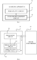
- FIG 5 is a schematic structural diagram of a charging apparatus according to an implementation of the present disclosure.
- the charging apparatus 50 includes a power supply circuit 52 and a charging management circuit 54.
- the power supply circuit 52 is configured to provide a charging power.
- the charging management circuit 54 is configured to: perform a constant-current charging on a battery according to the charging power provided by the power supply circuit 52; perform a constant-voltage charging on the battery according to the charging power provided by the power supply circuit 52 until a charging current of a battery cell of the battery reaches a target constant-voltage charging cut-off current, where the target constant-voltage charging cut-off current is larger than a standard constant-voltage charging cut-off current of the battery cell.
- the constant-current charging includes multiple charging stages, where each of the multiple charging stages corresponds to a charging current, and for any two adjacent charging stages, a charging current corresponding to a former charging stage is larger than a charging current corresponding to a later charging stage; in each of the multiple charging stages, apply a charging current corresponding to the charging stage to the battery until a voltage across the battery cell of the battery reaches a target constant-current charging cut-off voltage, where the target constant-current charging cut-off voltage is larger than a standard constant-current charging cut-off voltage of the battery cell.
- the battery includes multiple battery cells coupled in series.
- the charging management circuit is further configured to monitor the voltage across the battery cell in the constant-current charging.
- a voltage difference ⁇ V between the target constant-current charging cut-off voltage and the standard constant-current charging cut-off voltage satisfies 0 ⁇ V ⁇ 0.2V.
- a ratio N of the target constant-voltage charging cut-off current to the standard constant-voltage charging cut-off current of the battery cell satisfies 1 ⁇ N ⁇ 40.
- the target constant-voltage charging cut-off current is configured to make a power of the battery cell reach a battery capacity of the battery cell after the constant-voltage charging is completed.
- the charging apparatus 50 is applicable to a wired charging architecture or a wireless charging architecture.
- the charging apparatus 50 may be a power supply device (such as a power adaptor) in the wired charging architecture.
- the charging apparatus 50 may be a wireless transmitting device (such as a wireless charging base) or a device to-be-charged in the wireless charging architecture.
- implementations of the charging apparatus 50 in different charging architectures will be elaborated with examples in connection with FIG 6 to FIG 9 .
- the charging apparatus 50 is the power supply device (such as the power adaptor).
- the charging apparatus 50 can be coupled with a device to-be-charged 60 via a charging interface 56.
- the type of the charging interface 56 is not limited in implementations of the disclosure.
- the charging interface 56 may be a USB interface or a lightning interface.
- the USB interface may be a standard USB interface, a micro USB interface, or a Type-C interface.
- the charging control circuit 54 includes a communication control circuit 542 and a power adjusting circuit 544.
- the communication control circuit 542 is configured to, in the constant-current charging, communicate with the device to-be-charged 60 via the charging interface 56 and adjust, with the power adjusting circuit 544, an output current of the charging apparatus 50 according to information fed back by the device to-be-charged 60 to make the output current of the charging apparatus 50 match a charging current corresponding to a present charging stage.
- the power supply circuit 52 of the charging apparatus 50 can provide the device to-be-charged 60 with the charging power via a power line of the charging interface 56.
- the power line can be a VBUS line in the USB interface.
- the power supply circuit 52 can be implemented in a conventional manner, which is not limited herein.
- the power supply circuit 52 includes a transformer, a rectifying circuit and a filtering circuit on a primary side of the transformer, and a rectifying circuit and a filtering circuit on a secondary side of the transformer.
- the power adjusting circuit 544 can include, for example, a pulse width modulation (PWM) controller, a voltage feedback circuit, and/or a current feedback circuit.
- PWM pulse width modulation
- the communication control circuit 542 can be, for example, an MCU or other circuit units with a control function.
- the manner in which the communication control circuit 542 adjusts the output current of the charging apparatus 50 can be various. For instance, the communication control circuit 542 adjusts a reference voltage and/or a reference current of the voltage feedback circuit and/or the current feedback circuit of the power adjusting circuit 544 to adjust a duty cycle or a frequency of the PWM controller of the power adjusting circuit 544, thereby adjusting the output current of the charging apparatus 50.
- the manner of communication, the content communicated, or the master-slave relationship between the communication control circuit 542 and the device to-be-charged 60 is not limited in implementations of the disclosure.
- the communication control circuit 542 can communicate with the device to-be-charged 60 via a data line of the charging interface 56 (such as a D+ line and/or a D- line of the USB interface).
- the communication control circuit 542 can perform a one-way communication or a two-way communication (such as communication achieved through request(s) and response(s)) with the device to-be-charged 60.
- the content communicated between the communication control circuit 542 and the device to-be-charged 60 may be, for example, battery state information (such as the voltage across the battery or a power of the battery) or information for instructing the charging apparatus 50 to increase or decrease its own output current.
- the charging apparatus 50 adjusts its own output current according to the information fed back by the device to-be-charged 60 to make the output current of the charging apparatus 50 match the charging current corresponding to the present charging stage.
- the output current of the charging apparatus 50 can be directly applied to the battery for direct charging, and it is unnecessary for the device to-be-charged 60 to perform a constant-current control on the charging current of the battery, which is possible to reduce heating of the device to-be-charged.
- the output current of the charging apparatus 50 can be a constant DC or a current of varying waveform, such as a pulsating DC or an AC.
- the output current of the charging apparatus 50 is the current of varying waveform.
- the expression "the output current of the charging apparatus 50 matches the charging current corresponding to the present charging stage" means that a peak value or an average value of the output current of the charging apparatus 50 matches the charging current corresponding to the present charging stage.
- the manner of setting the output current of the charging apparatus 50 to the current of varying waveform can be various, and an example is given below.
- the power supply circuit 52 of the charging apparatus 50 usually includes a switch unit and transformer, a primary circuit on a primary side of the transformer, and a secondary circuit on a secondary side of the transformer.
- the primary circuit usually includes a rectifying circuit and a filtering circuit.
- the filtering circuit in the primary circuit can be removed, such that a voltage of pulsating waveform outputted by the rectifying circuit can be injected into the switch unit and transformer and be transferred, via the switch unit and transformer, from the primary side to the secondary side.
- the power supply circuit 52 includes a rectifying circuit 522, a switch unit (such as a MOS transistor) and transformer 524, and a secondary circuit 528 (including a secondary rectifying circuit and a secondary filtering circuit, for example).
- the rectifying circuit 522 is configured to rectify an input AC to output a voltage of pulsating waveform.
- the switch unit and transformer 524 is configured to couple the voltage of pulsating waveform from a primary side of the transformer to a secondary side of the transformer.
- the secondary circuit 528 is configured to generate the output current of the charging apparatus 50 according to an output voltage of the transformer 528.
- the communication control circuit 542 is configured to adjust, with the power adjusting circuit 544, the output current of the charging apparatus 50 (such as adjusting, with the power adjusting circuit 544, (that is, a switch-on time and a switch-off time) of the switch unit) according to the information fed back by the device to-be-charged 60 to make a peak value or an average value of the output current of the charging apparatus 50 match the charging current corresponding to the present charging stage.
- a liquid aluminum electrolytic capacitor is usually used for filtering.
- the liquid aluminum electrolytic capacitor has a large volume and bursts easily. Taking the above into consideration, the filtering circuit on the primary side can be removed, and the voltage of pulsating waveform obtained after rectification is directly injected into the switch unit and transformer, thereby reducing the volume of the power supply device.
- the liquid aluminum electrolytic capacitor on the primary side since the liquid aluminum electrolytic capacitor on the primary side has a short service life and tends to burst, the liquid aluminum electrolytic capacitor on the primary side can be removed, such that the power supply device can have a longer service life and be safer.
- the charging apparatus 50 can be applied to the wireless charging architecture.
- the charging apparatus 50 can be the wireless transmitting device or the device to-be-charged.
- the charging apparatus 50 is the wireless transmitting device. As illustrated in FIG 8 , the charging apparatus 50 further includes a wireless transmitting circuit 57.
- the charging control circuit 54 is configured to, in the constant-current charging, perform a wireless communication with a device to-be-charged 80 and adjust, according to information fed back by the device to-be-charged 80, a transmission power of the wireless transmitting circuit 57 to make the transmission power of the wireless transmitting circuit 57 match a charging current corresponding to a present charging stage.
- the power supply circuit 52 can be realized in different manners.
- the power supply circuit 52 can include a rectifying circuit and a filtering circuit which are configured to convert an AC into an input voltage of the wireless transmitting circuit 57.
- the charging apparatus 50 is coupled with a power supply device (such as a power adaptor, which is not illustrated in FIG 8 ) via an interface and provides a power inputted via the interface from the power supply device to the wireless transmitting circuit.
- the power supply circuit 52 can be an interface circuit in the charging apparatus 50 corresponding to an interface configured to be coupled with the power supply device.
- the manner in which the charging control circuit 54 is realized and the manner in which the charging control circuit 54 adjusts the transmission power of the wireless transmitting circuit 57 can be various.
- the charging control circuit 54 includes only a circuit with a communication function.
- the charging control circuit 54 is configured to receive the information fed back by the device to-be-charged 80 and communicate with the power supply device according to the information fed back by the device to-be-charged 80 to instruct the power supply device to adjust an output voltage and/or an output current, thereby adjusting the transmission power of the wireless transmitting circuit 57.
- the charging control circuit 54 includes a communication control circuit and a power adjusting circuit (not illustrated in FIG 8 ).
- the communication control circuit can adjust, according to the information fed back by the device to-be-charged 80, a duty cycle or a frequency of a control signal transmitted by the power adjusting circuit to adjust the transmission power of the wireless transmitting circuit 57.
- the charging control circuit 54 can perform a wireless communication with the device to-be-charged 80 based on Bluetooth, Wi-Fi, or backscatter modulation (or power load modulation).
- the charging control circuit 54 can perform a one-way communication or a two way communication (such as communication achieved through request(s) and response(s)) with the device to-be-charged 80.
- the content communicated between the charging control circuit 54 and the device to-be-charged 80 may be, for example, battery state information (such as the voltage across the battery or a power of the battery) or information for instructing the wireless transmitting device to increase or decrease its own transmission power.
- the charging apparatus 50 is a device to-be-charged.
- the power supply circuit includes a wireless receiving circuit 523.
- the charging control circuit includes a charging management circuit 543.
- the wireless receiving circuit 523 is configured to convert a wireless charging signal received into an input voltage of a charging line 58 between the wireless receiving circuit 523 and the battery.
- the charging apparatus 50 further includes a step-down circuit 59.
- the step-down circuit 59 is configured to decrease a voltage in the charging line 58.
- the charging management circuit 543 is configured to perform a constant-current control on a current inputted into the battery.
- the charging apparatus is provided with the step-down circuit.
- the wireless charging signal can be transmitted with a high voltage between the wireless transmitting device and the charging apparatus, which is beneficial to decreasing a current in the wireless receiving circuit, thereby reducing heating of the device to-be-charged.
- the step-down circuit 59 can be located between the wireless receiving circuit 523 and the charging management circuit 543 or located between the charging management circuit 543 and the battery.
- the step-down circuit 59 can be a step-down circuit having a step-down conversion efficiency larger than that of the charging management circuit 543 and may be, for example, a charge pump.
- the charging apparatus 50 further includes a communication control circuit 53.
- the communication control circuit 53 is configured to perform a wireless communication with a wireless transmitting device 90 and instruct the wireless transmitting device 90 to adjust the wireless charging signal according to a voltage difference between an input voltage of the charging management circuit 543 and an output voltage of the charging management circuit 543, to decrease the voltage difference.
- the conversion efficiency of the charging management circuit 543 can be improved by decreasing the voltage difference, thereby further reducing heating of the device to-be-charged.
- the "device to-be-charged" can include but is not limited to a device configured via a wired line and/or a wireless interface to receive/transmit communication signals.
- the wired line may include, but are not limited to, at least one of a public switched telephone network (PSTN), a digital subscriber line (DSL), a digital cable, a direct connection cable, and/or another data connection line or network connection line.
- Examples of the wireless interface may include, but are not limited to, a wireless interface with a cellular network, a wireless local area network (WLAN), a digital television network (such as a digital video broadcasting-handheld (DVB-H) network), a satellite network, an amplitude modulation-frequency modulation (AM-FM) broadcast transmitter, and/or with another communication terminal.
- a communication terminal configured to communicate via a wireless interface may be called a "wireless communication terminal", a “wireless terminal”, and/or a "mobile terminal”.
- Examples of a mobile terminal may include, but are not limited to, a satellite or cellular telephone, a personal communication system (PCS) terminal capable of cellular radio telephone, data processing, fax, and/or data communication, a personal digital assistant (PDA) equipped with radio telephone, pager, Internet/Intranet access, web browsing, notebook, calendar, and/or global positioning system (GPS) receiver, and/or other electronic devices equipped with radio telephone capability such as a conventional laptop or a handheld receiver.
- the device to-be-charged can refer to a mobile terminal device or a handheld terminal device, such as a mobile phone, pad, etc.
- the device to-be-charged of the disclosure can refer to a system-on-chip, where the battery of the terminal device may or may not belong to the system-on-chip.
- the above implementations may be wholly or partially implemented in software, hardware, firmware, or any combination thereof.
- the implementations may wholly or partially take the form of computer program products.
- the computer program product includes one or more computer instructions.
- the computer may be a general-purpose computer, a special-purpose computer, a computer network, or other programmable apparatuses.
- the computer instructions may be stored in a computer readable storage medium, or transmitted from one computer readable storage medium to another computer readable storage medium.
- the computer instructions may be transmitted from one website, computer, server, or data center to another website, computer, server, or data center in a wired manner (such as a coaxial-cable, an optical fiber, a digital subscriber line (DSL)) or a wireless manner (such as infrared, wireless, microwave, or the like).
- the computer readable storage medium may be any usable medium accessible to the computer, or a storage device (such as a server, a date center, or the like) which includes one or more usable mediums integrated.
- the usable medium can be a magnetic medium (such as a floppy disk, a hard disk, or a magnetic tape), an optical medium (such as a digital video disc (DVD)), a semiperformor medium (such as a solid state disk (SSD)), or the like.
- a magnetic medium such as a floppy disk, a hard disk, or a magnetic tape
- an optical medium such as a digital video disc (DVD)
- DVD digital video disc
- SSD solid state disk
- the systems, apparatuses, and methods disclosed in implementations herein may also be implemented in various other manners.
- the above apparatus implementations are merely illustrative, e.g., the division of is only a division of logical functions, and there may exist other ways of division in practice, e.g., multiple units or components may be combined or may be integrated into another system, or some features may be ignored or not included.
- the coupling or direct coupling or communication connection as illustrated or discussed may be an indirect coupling or communication connection through some interface, device or unit, and may be electrical, mechanical, or otherwise.
- Separated units as illustrated may or may not be physically separated.
- Components or parts displayed as units may or may not be physical units, and may reside at one location or may be distributed to multiple networked units. Some or all of the units may be selectively adopted according to practical needs to achieve desired objectives of the disclosure.
- various functional units described in implementations herein may be integrated into one processing unit or may be present as a number of physically separated units, and two or more units may be integrated into one.
Landscapes
- Engineering & Computer Science (AREA)
- Power Engineering (AREA)
- Manufacturing & Machinery (AREA)
- Chemical & Material Sciences (AREA)
- Chemical Kinetics & Catalysis (AREA)
- Electrochemistry (AREA)
- General Chemical & Material Sciences (AREA)
- Computer Networks & Wireless Communication (AREA)
- Charge And Discharge Circuits For Batteries Or The Like (AREA)
- Secondary Cells (AREA)
Abstract
Description
- This disclosure relates to the field of charging technology, and more particularly to a charging method and a charging apparatus.
- A battery cell is usually charged in a constant-current and constant-voltage manner. In other words, the battery cell is first charged in a constant-current manner, and when a voltage across the battery cell reaches a standard constant-current charging cut-off voltage, proceed to a constant-voltage charging stage. In the constant-voltage charging stage, the battery cell is charged with a high voltage (that is, the standard constant-current charging cut-off voltage). As the charging process proceeds, a charging current of the battery cell gradually decreases. When the charging current of the battery cell reaches a standard constant-voltage charging cut-off current, charging is completed.
- In the above charging process, the constant-voltage charging stage usually takes a long time, which results in a low charging speed of the battery cell.
- According to implementations of the present disclosure, a charging method and a charging apparatus are provided, which is possible to increase a charging speed of a battery cell.
- In a first aspect of the present disclosure, a charging method is provided. The charging method includes the following. Perform a constant-current charging of a battery. The constant-current charging includes multiple charging stages, where each of the multiple charging stages corresponds to a charging current, and for any two adjacent charging stages, a charging current corresponding to a former charging stage is larger than a charging current corresponding to a later charging stage; in each of the multiple charging stages, apply a charging current corresponding to the charging stage to the battery until a voltage across a battery cell of the battery reaches a target constant-current charging cut-off voltage, where the target constant-current charging cut-off voltage is larger than a standard constant-current charging cut-off voltage of the battery cell. Perform a constant-voltage charging of the battery until a charging current of the battery cell of the battery reaches a target constant-voltage charging cut-off current, where the target constant-voltage charging cut-off current is larger than a standard constant-voltage charging cut-off current of the battery cell.
- According to a second aspect of the present disclosure, a charging apparatus is provided. The charging apparatus includes a power supply circuit and a charging control circuit. The power supply circuit is configured to provide a charging power. The charging control circuit is configured to: perform a constant-current charging of a battery according to the charging power provided by the power supply circuit; perform a constant-voltage charging of the battery according to the charging power provided by the power supply circuit until a charging current of a battery cell of the battery reaches a target constant-voltage charging cut-off current, where the target constant-voltage charging cut-off current is larger than a standard constant-voltage charging cut-off current of the battery cell. The constant-current charging includes multiple charging stages, where each of the multiple charging stages corresponds to a charging current, and for any two adjacent charging stages, a charging current corresponding to a former charging stage is larger than a charging current corresponding to a later charging stage; in each of the multiple charging stages, apply a charging current corresponding to the charging stage to the battery until a voltage across the battery cell of the battery reaches a target constant-current charging cut-off voltage, where the target constant-current charging cut-off voltage is larger than a standard constant-current charging cut-off voltage of the battery cell.
- According to implementations of the present disclosure, a constant-current charging cut-off voltage is set higher and a constant-voltage charging cut-off current is set larger, and the constant-current charging is performed in a multi-stage constant-current manner, thereby increasing a charging speed of the battery cell.
-
-
FIG 1 is a schematic flowchart of a charging method according to an implementation of the present disclosure. -
FIG 2 is an exemplary diagram of the charging method according to an implementation of the present disclosure. -
FIG 3 is an exemplary diagram illustrating charging stages of the charging method according to an implementation of the present disclosure. -
FIG 4 is an exemplary diagram of the charging method according to another implementation of the present disclosure. -
FIG 5 is a schematic structural diagram of a charging apparatus according to an implementation of the present disclosure. -
FIG 6 is an exemplary diagram illustrating a manner in which the charging apparatus is used in a wired charging architecture. -
FIG 7 is another exemplary diagram illustrating a manner in which the charging apparatus is used in a wired charging architecture. -
FIG 8 is an exemplary diagram illustrating a manner in which the charging apparatus is used in a wireless charging architecture. -
FIG 9 is another exemplary diagram illustrating a manner in which the charging apparatus is used in a wireless charging architecture. - The "battery" referred to herein may be a lithium battery. The lithium battery may be an ordinary lithium-ion battery or a polymer lithium-ion battery.
- The "battery" referred to herein may include one battery cell or multiple battery cells. The "battery cell" may sometimes be referred to as "battery pack" or "cell".
- The "standard constant-current charging cut-off voltage" may also be referred to as "recommended constant-current limited charging voltage" or "well-known constant-current limited charging voltage". The value of the standard constant-current charging cut-off voltage depends on the type of the battery cell, which is not limited herein.
- As an example, an anode of the battery cell is made of graphite, soft carbon, or hard carbon, a cathode of the battery cell is made of lithium cobalt oxide, lithium manganate, lithium nickel cobaltate, or lithium nickel cobalt manganese oxide, and accordingly the standard constant-current charging cut-off voltage of the battery cell can be 4.2∼5.0V (volt).
- For example, the anode of the battery cell is made of graphite, and the cathode of the battery cell is made of lithium cobalt oxide, and accordingly the standard constant-current charging cut-off voltage of the battery cell can be 4.40V or 4.45V.
- As another example, the anode of the battery cell is made of graphite, and the cathode of the battery cell is made of lithium iron phosphate, and accordingly the standard constant-current charging cut-off voltage of the battery cell can be 3.6-3.8V, for example, 3.7V.
- The "standard constant-voltage charging cut-off current" referred to herein may also be referred to as "recommended constant-voltage limited charging current" or "well-known constant-voltage limited charging current". The magnitude of the standard constant-voltage charging cut-off current may be, for example, 0.01∼0.1C (coulomb).
- The battery cell is usually charged in a constant-current and constant-voltage manner. Specifically, the battery cell is first charged in a constant-current manner until a voltage across the battery cell reaches the standard constant-current charging cut-off voltage. Then the battery cell is charged with the standard constant-current charging cut-off voltage in a constant-voltage manner. When the charging process proceeds, a charging current of the battery cell gradually decreases. When the charging current of the battery cell reaches the standard constant-voltage charging cut-off current, charging is completed.
- In a constant-current charging stage, the voltage across the battery cell usually includes two parts: one is a stable voltage between a positive electrode and a negative electrode of the battery cell, the other is a voltage caused by internal resistance and/or polarization of the battery cell. In a constant-voltage charging stage, the charging current gradually decreases, and the voltage caused by internal resistance and/or polarization of the battery cell also gradually decreases. When the charging current of the battery cell is decreased to the standard constant-voltage charging cut-off current, the voltage caused by internal resistance and/or polarization of the battery cell will be low enough to be ignored, and the voltage across the battery cell reaches approximately the standard constant-current charging cut-off voltage.
- However, the constant-voltage charging stage in the above charging manner usually takes a long time, which results in a low charging speed of the battery cell. In addition, in the constant-voltage charging stage, the battery is always in a high-voltage state, which will shorten a service life of the battery. If the constant-voltage charging stage is removed with only the constant-current charging stage left, it will be difficult to control the battery cell to be fully charged. Therefore, it is necessary to improve the conventional constant-voltage and constant-current charging manner to increase a charging speed in the constant-voltage and constant-current manner.
-
FIG. 1 is a schematic flowchart of a charging method according to an implementation of the present disclosure. The charging method illustrated inFIG. 1 includes operations atblock 12 toblock 14, which will be described in detail in the following. - At
block 12, perform a constant-current charging on a battery. The constant-current charging includes multiple charging stages, where each of the multiple charging stages corresponds to a charging current (also referred to as "charge rate"), and for any two adjacent charging stages, a charging current (also referred to as "charge rate") corresponding to a former charging stage is larger than a charging current (also referred to as "charge rate") corresponding to a later charging stage. In each of the multiple charging stages, apply a charging current corresponding to the charging stage to the battery until a voltage across a battery cell of the battery reaches a target constant-current charging cut-off voltage, where the target constant-current charging cut-off voltage is larger than a standard constant-current charging cut-off voltage of the battery cell. - At
block 14, perform a constant-voltage charging on the battery until a charging current of the battery cell of the battery reaches a target constant-voltage charging cut-off current, where the target constant-voltage charging cut-off current is larger than a standard constant-voltage charging cut-off current of the battery cell. A voltage used in the constant-voltage charging can be, for example, the above constant-current charging cut-off voltage, that is, the constant-current charging cut-off voltage can be directly used as a charging voltage for a constant-voltage charging stage. As an example, an anode of the battery cell is made of graphite, soft carbon, or hard carbon, a cathode of the battery cell is made of lithium cobalt oxide, lithium manganate, lithium nickel cobaltate, or lithium nickel cobalt manganese oxide, and accordingly the standard constant-current charging cut-off voltage of the battery cell can be 4.2∼5.0V For example, the anode of the battery cell is made of graphite, and the cathode of the battery cell is made of lithium cobalt oxide, and accordingly the standard constant-current charging cut-off voltage of the battery cell can be 4.40V or 4.45V. As another example, the anode of the battery cell is made of graphite, and the cathode of the battery cell is made of lithium iron phosphate, and accordingly the standard constant-current charging cut-off voltage of the battery cell can be 3.6-3.8V, for example, 3.7V In some implementations, a voltage used in the constant-voltage charging stage can also be larger or lower than the constant-current charging cut-off voltage according to actual needs, as long as the voltage used in the constant-voltage charging stage is larger than a voltage across the battery (not including a polarization voltage of the battery) when the constant-current charging stage is completed, which is not limited in implementations of the disclosure. - By adopting the charging method provided in implementations of the disclosure, the constant-current charging cut-off voltage in the constant-current charging and a constant-voltage charging cut-off current in the constant-voltage charging can be increased, such that the constant-current charging stage can be prolonged and the constant-voltage charging stage can be shortened to increase a charging speed of the battery. On the other hand, in implementations of the disclosure, the constant-current charging is implemented as multi-stage constant-current charging. Compared with a traditional constant-current charging in which only a single current is adopted, based on the multi-stage constant-current charging, the constant-current charging stage can be further prolonged and the constant-voltage charging stage can be further shortened, thereby further increasing the charging speed of the battery. To summarize, the charging method provided herein can achieve the following advantageous effects. Without decreasing a charging power of the battery, the constant-voltage charging stage can be shortened, thereby increasing the charging speed. In addition, a shorter constant-voltage charging stage will lead to a shorter time period of charging with a high voltage, which can prolong a service life of the battery.
- The magnitude of the target constant-current charging cut-off voltage is not limited in implementations of the disclosure. The target constant-current charging cut-off voltage can be configured according to the type of the battery, an expected charging speed, or the like. In an implementation, the target constant-current charging cut-off voltage can be configured as follows. A voltage difference ΔV between the target constant-current charging cut-off voltage and the standard constant-current charging cut-off voltage satisfies 0< ΔV<0.2V.
- The magnitude of the target constant-voltage charging cut-off current is not limited in implementations of the disclosure. The target constant-voltage charging cut-off current can be configured according to the type of the battery, an expected charging speed, an expected fully-charged battery power, or the like. In an implementation, the target constant-voltage charging cut-off current is configured such that a power of the battery cell reaches a battery capacity of the battery cell after the constant-voltage charging is completed.
- The expression "reach" means "be approximately equal to" and does not require that the power of the battery cell be completely equal to the battery capacity of the battery cell. As an example, a standard capacity of the battery cell is Q0. The target constant-voltage charging cut-off current can be configured such that an actual capacity of the battery Qz satisfies 0.98Q0<Qz < 1.02Qo when the constant-voltage charging stage is completed.
- In an implementation, the target constant-voltage charging cut-off current is configured as follows. A ratio N of the target constant-voltage charging cut-off current to the standard constant-voltage charging cut-off current of the battery cell satisfies 1<N<40, where N can be an integer or a decimal.
- The battery in implementations illustrated in
FIG 1 can include one battery cell or multiple battery cells, such as multiple battery cells coupled in series. If the battery includes multiple battery cells, the battery cell in implementations illustrated inFIG 1 can be any one of the multiple battery cells. - The manner of determining whether the voltage across the battery cell of the battery reaches the target constant-current charging cut-off voltage can be various. For example, whether the voltage across the battery cell reaches the target constant-current charging cut-off voltage can be predicted according to how long the battery cell has been charged. For another example, the voltage across the battery cell of the battery can be continuously monitored with a monitoring circuit to determine whether the voltage across the battery cell reaches the target constant-current charging cut-off voltage.
- Similarly, the manner of determining whether the charging current of the battery cell of the battery reaches the target constant-voltage charging cut-off current can be various. For example, whether the charging current of the battery cell reaches the target constant-voltage charging cut-off current can be predicted according to how long the battery cell has been charged. For another example, the charging current of the battery cell can be continuously monitored with a monitoring circuit to determine whether the charging current of the battery cell reaches the target constant-voltage charging cut-off current.
- The following will describe in further detail the charging method provided in implementations of the disclosure with examples in connection with
FIG 2 to FIG 4 . -
FIG 2 is an exemplary diagram of the charging method according to an implementation of the present disclosure. In an example illustrated inFIG 2 , the battery includes a single battery cell. In addition, in the example illustrated inFIG 2 , charging currents I0, I1, I2...In used for the constant-current charging are set for the battery in advance, where I0>I1>I2>...>In. A charging method illustrated inFIG 2 includes operations atblock 22 to block 28, which will be described below. - At
block 22, apply charging current I0 to the battery until the voltage across the battery reaches Vtr (Vtr represents the target constant-current charging cut-off voltage), and then the charging current is decreased to I1. - At
block 24, apply charging current I1 to the battery until the voltage across the battery reaches Vtr, and then the charging current is decreased to h. - At
block 26, in a similar manner, apply charging current In to the battery until the voltage across the battery reaches Vtr, and then the method proceeds to the constant-voltage charging stage. - At
block 28, perform the constant-voltage charging by applying charging voltage Vtr to the battery, and charging ends when the charging current is decreased to Itr (Itr represents the constant-voltage charging cut-off current). - In the example illustrated in
FIG 2 , the charging current of the battery decreases in a step-like manner from operations atblock 22 to operations atblock 28. As such, in the constant-current charging, the battery can be charged in a manner of multi-stage constant-current, thereby prolonging the constant-current charging as much as possible.FIG 3 illustrates current variance in the whole charging process when n is equal to 2. -
FIG 4 is an exemplary diagram of the charging method according to another implementation of the present disclosure. The charging method illustrated inFIG 4 is similar to that illustrated inFIG 2 . The difference lies in that, in the example illustrated inFIG 4 , the battery includes multiple battery cells coupled in series. The method illustrated inFIG 4 includes operations atblock 42 to block 48, which will be described below. - At
block 42, apply charging current I0 to the battery and a voltage across each of the multiple battery cells is monitored during charging. When a voltage across any one of the multiple battery cells reaches Vtr, the charging current is decreased to I1. - At
block 44, apply charging current I1 to the battery and the voltage across each of the multiple battery cells is monitored during charging. When the voltage across any one of the multiple battery cells reaches Vtr, the charging current is decreased to h. - At
block 46, in a similar manner, apply charging current In to the battery and the voltage across each of the multiple battery cells is monitored during charging. When the voltage across any one of the multiple battery cells reaches Vtr, the method proceeds to the constant-voltage charging stage. - At
block 48, perform the constant-voltage charging by applying charging voltage Vtr to the battery and a charging current of any one of the multiple battery cells (or each of the multiple battery cells) is monitored during charging. Charging ends when the charging current of any one of the multiple battery cells (or each of the multiple battery cells) is decreased to Itr. - It is to be noted that, the scenario to which the charging method illustrated in
FIG 1 is applied is not limited in implementations of the disclosure. The charging method illustrated inFIG 1 is applicable to a wired charging architecture or a wireless charging architecture. For example, the charging method illustrated inFIG 1 is applicable to the wired charging architecture and is performed by a power supply device (such as a power adaptor) in the wired charging architecture. For another example, the charging method illustrated inFIG 1 is applicable to the wireless charging architecture and is performed by a wireless transmitting device (such as a wireless charging base) or a device to-be-charged in the wireless charging architecture. Hereinafter, implementations of the charging method illustrated inFIG 1 in different charging architectures will be elaborated with examples in connection with specific implementations. - As an example, the charging method illustrated in
FIG 1 can be applied to a wired charging architecture. In the wired charging architecture, the power supply device can be coupled with a device to-be-charged via a charging interface. The type of the charging interface is not limited in implementations of the disclosure. For example, the charging interface may be a universal serial bus (USB) interface or a lightning interface. The USB interface may be a standard USB interface, a micro USB interface, or a Type-C interface. - In the wired charging architecture, the charging method illustrated in
FIG 1 can be performed by the power supply device or the device to-be-charged. - In an implementation, the charging method illustrated in
FIG 1 is performed by the power supply device. Operations atblock 12 include the following. In the constant-current charging, the power supply device communicates with the device to-be-charged via the charging interface and adjusts, according to information fed back by the device to-be-charged, an output current of the power supply device to make the output current of the power supply device match a charging current corresponding to a present charging stage. - The manner of communication, the content communicated, or the master-slave relationship in communication between the power supply device and the device to-be-charged is not limited in implementations of the disclosure. For example, the power supply device can communicate with the device to-be-charged via a data line of the charging interface (such as a D+ line and/or a D-line of the USB interface). The power supply device can perform a one-way communication with the device to-be-charged or perform a two-way communication (such as communication achieved through request(s) and response(s)) with the device to-be-charged. The content communicated between the power supply device and the device to-be-charged (that is, the information fed back by the device to-be-charged) may be, for example, battery state information (such as the voltage across the battery or a power of the battery) or information for instructing the power supply device to increase or decrease its own output current.
- In the above implementation, the power supply device adjusts its own output current according to the information fed back by the device to-be-charged to make the output current of the power supply device match the charging current corresponding to the present charging stage. As such, the output current of the power supply device can be directly applied to the battery for direct charging, and it is unnecessary for the device to-be-charged to perform a constant-current control on the charging current of the battery, which is possible to reduce heating of the device to-be-charged.
- It is to be understood that, the output current of the power supply device can be a constant direct current (DC) or a current of varying waveform, such as a pulsating DC or an alternating current (AC). As an example, the output current of the power supply device is the current of varying waveform. The expression "the output current of the power supply device matches the charging current corresponding to the present charging stage" means that a peak value or an average value of the output current of the power supply device matches the charging current corresponding to the present charging stage. By charging the battery with the current of varying waveform, polarization of the battery can be reduced, thereby prolonging the service life of the battery.
- The manner of setting the output current of the power supply device to the current of varying waveform can be various, and an example is given below.
- The power supply device usually includes a switch unit and transformer, a primary circuit on a primary side of the transformer, and a secondary circuit on a secondary side of the transformer. The primary circuit usually includes a rectifying circuit and a filtering circuit. In order to make the power supply device output the current of varying waveform, the filtering circuit in the primary circuit can be removed, such that a voltage of pulsating waveform outputted by the rectifying circuit can be injected into the switch unit and transformer, and energy can be transferred, via the switch unit and transformer, from the primary side to the secondary side.
- If the above is implemented, the charging method illustrated in
FIG 1 further includes the following. An input AC is rectified to output a voltage of pulsating waveform. The voltage of pulsating waveform is coupled from the primary side of the transformer to the secondary side of the transformer. The output current of the power supply device is generated according to an output voltage of the transformer. - The output current of the power supply device is adjusted according to the information fed back by the device to-be-charged to make the output current of the power supply device match the charging current corresponding to the present charging stage as follows. The output current of the power supply device is adjusted according to the information fed back by the device to-be-charged to make a peak value or an average value of the output current of the power supply device match the charging current corresponding to the present charging stage.
- For the filtering circuit on the primary side, a liquid aluminum electrolytic capacitor is usually used for filtering. However, the liquid aluminum electrolytic capacitor has a large volume and bursts easily. Taking the above into consideration, the filtering circuit on the primary side can be removed, and the voltage of pulsating waveform obtained after rectification is directly injected into the switch unit and transformer, thereby reducing the volume of the power supply device. In addition, since the liquid aluminum electrolytic capacitor on the primary side has a short service life and tends to burst, the liquid aluminum electrolytic capacitor on the primary side can be removed, such that the power supply device can have a longer service life and be safer.
- As another example, the charging method illustrated in
FIG 1 can be applied to a wireless charging architecture in which the wireless transmitting device is used for wireless charging. - In this example, the charging method illustrated in
FIG 1 can be performed by the wireless transmitting device or the device to-be-charged. - In an implementation, the charging method illustrated in
FIG 1 is performed by the wireless transmitting device. In this case, operations atblock 12 include the following. In the constant-current charging, the wireless transmitting device performs a wireless communication with the device to-be-charged and adjusts, according to information fed back by the device to-be-charged, a transmission power of the wireless transmitting device to make the transmission power of the wireless transmitting device match a charging current corresponding to a present charging stage. - There is no restriction on the manner of communication, the content communicated, or the master-slave relationship between the wireless transmitting device and the device to-be-charged in implementations of the disclosure.
- For example, the wireless transmitting device can perform a wireless communication with the device to-be-charged based on Bluetooth, wireless fidelity (Wi-Fi), or backscatter modulation (or power load modulation).
- The wireless transmitting device can perform a one-way communication or a two-way communication (such as communication achieved through request(s) and response(s)) with the device to-be-charged. The content communicated between the wireless transmitting device and the device to-be-charged (that is, the information fed back by the device to-be-charged) may be, for example, battery state information (such as the voltage across the battery or a power of the battery) or information for instructing the wireless transmitting device to increase or decrease its own transmission power.
- The manner in which the wireless transmitting device adjusts its own transmission power can be various. For example, the wireless transmitting device can be coupled with a power supply device and transmit a wireless charging signal according to an input voltage provided by the power supply device. In this situation, the wireless transmitting device can communicate with the power supply device to instruct the power supply device to adjust the input voltage, thereby adjusting a transmission power of the wireless charging signal. For another example, the wireless transmitting device includes a power adjusting apparatus and is configured to adjust the transmission power of the wireless charging signal by adjusting a duty cycle and/or a frequency of a control signal transmitted by the power adjusting apparatus.
- In an implementation, the charging method illustrated in
FIG 1 is performed by the device to-be-charged. The charging method illustrated inFIG 1 further includes the following. A wireless charging signal received is converted, with a wireless receiving circuit, into an input voltage of a charging line between the wireless receiving circuit and the battery. Operations atblock 12 include the following. Decrease, with a step-down circuit, a voltage in the charging line and perform, with a charging management circuit, a constant-current control on a current inputted into the battery. - There is no restriction on the position of the step-down circuit on the charging line in implementations of the disclosure. For example, the step-down circuit can be located between the charging management circuit and the battery or located between the wireless receiving circuit and the charging management circuit.
- In this implementation, the device to-be-charged is provided with the step-down circuit. In this way, the wireless charging signal can be transmitted with a high voltage between the wireless transmitting device and the device to-be-charged, which is beneficial to decreasing a current in the wireless receiving circuit, thereby reducing heating of the device to-be-charged.
- The step-down circuit can be a step-down circuit having a step-down conversion efficiency larger than that of the charging management circuit and may be, for example, a charge pump.
- In an implementation, in order to further reduce heating of the device to-be-charged, the charging method illustrated in
FIG 1 further includes the following. Perform a wireless communication with a wireless transmitting device and instruct the wireless transmitting device to adjust the wireless charging signal according to a voltage difference between an input voltage of the charging management circuit and an output voltage of the charging management circuit, to decrease the voltage difference. Since a conversion efficiency of the charging management circuit has a positive correlation with the voltage difference between the input voltage of the charging management circuit and the output voltage of the charging management circuit, the conversion efficiency of the charging management circuit can be improved by decreasing the voltage difference, thereby further reducing heating of the device to-be-charged. - Method implementations of the disclosure have been described in detail above with reference to
FIG 1 to FIG 4 . The following will describe in detail apparatus implementations of the disclosure with reference toFIG 5 . It is to be understood that, method implementations and apparatus implementations correspond to each other in terms of description. Therefore, for details not elaborated in apparatus implementations, reference can be made to the foregoing method implementations. -
FIG 5 is a schematic structural diagram of a charging apparatus according to an implementation of the present disclosure. As illustrated inFIG 5 , the chargingapparatus 50 includes apower supply circuit 52 and acharging management circuit 54. Thepower supply circuit 52 is configured to provide a charging power. Thecharging management circuit 54 is configured to: perform a constant-current charging on a battery according to the charging power provided by thepower supply circuit 52; perform a constant-voltage charging on the battery according to the charging power provided by thepower supply circuit 52 until a charging current of a battery cell of the battery reaches a target constant-voltage charging cut-off current, where the target constant-voltage charging cut-off current is larger than a standard constant-voltage charging cut-off current of the battery cell. The constant-current charging includes multiple charging stages, where each of the multiple charging stages corresponds to a charging current, and for any two adjacent charging stages, a charging current corresponding to a former charging stage is larger than a charging current corresponding to a later charging stage; in each of the multiple charging stages, apply a charging current corresponding to the charging stage to the battery until a voltage across the battery cell of the battery reaches a target constant-current charging cut-off voltage, where the target constant-current charging cut-off voltage is larger than a standard constant-current charging cut-off voltage of the battery cell. - In an implementation, the battery includes multiple battery cells coupled in series. The charging management circuit is further configured to monitor the voltage across the battery cell in the constant-current charging.
- In an implementation, a voltage difference ΔV between the target constant-current charging cut-off voltage and the standard constant-current charging cut-off voltage satisfies 0<Δ V<0.2V.
- In an implementation, a ratio N of the target constant-voltage charging cut-off current to the standard constant-voltage charging cut-off current of the battery cell satisfies 1<N<40.
- In an implementation, the target constant-voltage charging cut-off current is configured to make a power of the battery cell reach a battery capacity of the battery cell after the constant-voltage charging is completed.
- It is to be noted that, the scenario to which the charging
apparatus 50 is applied is not limited in implementations of the disclosure. The chargingapparatus 50 is applicable to a wired charging architecture or a wireless charging architecture. For example, the chargingapparatus 50 may be a power supply device (such as a power adaptor) in the wired charging architecture. For another example, the chargingapparatus 50 may be a wireless transmitting device (such as a wireless charging base) or a device to-be-charged in the wireless charging architecture. Hereinafter, implementations of the chargingapparatus 50 in different charging architectures will be elaborated with examples in connection withFIG 6 to FIG 9 . - As an example, as illustrated in
FIG 6 , the chargingapparatus 50 is the power supply device (such as the power adaptor). The chargingapparatus 50 can be coupled with a device to-be-charged 60 via a charginginterface 56. The type of the charginginterface 56 is not limited in implementations of the disclosure. For example, the charginginterface 56 may be a USB interface or a lightning interface. The USB interface may be a standard USB interface, a micro USB interface, or a Type-C interface. - As illustrated in
FIG 6 , the chargingcontrol circuit 54 includes acommunication control circuit 542 and apower adjusting circuit 544. Thecommunication control circuit 542 is configured to, in the constant-current charging, communicate with the device to-be-charged 60 via the charginginterface 56 and adjust, with thepower adjusting circuit 544, an output current of the chargingapparatus 50 according to information fed back by the device to-be-charged 60 to make the output current of the chargingapparatus 50 match a charging current corresponding to a present charging stage. - The
power supply circuit 52 of the chargingapparatus 50 can provide the device to-be-charged 60 with the charging power via a power line of the charginginterface 56. When the charginginterface 56 is the USB interface, the power line can be a VBUS line in the USB interface. Thepower supply circuit 52 can be implemented in a conventional manner, which is not limited herein. For example, thepower supply circuit 52 includes a transformer, a rectifying circuit and a filtering circuit on a primary side of the transformer, and a rectifying circuit and a filtering circuit on a secondary side of the transformer. - The
power adjusting circuit 544 can include, for example, a pulse width modulation (PWM) controller, a voltage feedback circuit, and/or a current feedback circuit. - The
communication control circuit 542 can be, for example, an MCU or other circuit units with a control function. The manner in which thecommunication control circuit 542 adjusts the output current of the chargingapparatus 50 can be various. For instance, thecommunication control circuit 542 adjusts a reference voltage and/or a reference current of the voltage feedback circuit and/or the current feedback circuit of thepower adjusting circuit 544 to adjust a duty cycle or a frequency of the PWM controller of thepower adjusting circuit 544, thereby adjusting the output current of the chargingapparatus 50. - The manner of communication, the content communicated, or the master-slave relationship between the
communication control circuit 542 and the device to-be-charged 60 is not limited in implementations of the disclosure. For example, thecommunication control circuit 542 can communicate with the device to-be-charged 60 via a data line of the charging interface 56 (such as a D+ line and/or a D- line of the USB interface). Thecommunication control circuit 542 can perform a one-way communication or a two-way communication (such as communication achieved through request(s) and response(s)) with the device to-be-charged 60. The content communicated between thecommunication control circuit 542 and the device to-be-charged 60 (that is, the information fed back by the device to-be-charged 60) may be, for example, battery state information (such as the voltage across the battery or a power of the battery) or information for instructing the chargingapparatus 50 to increase or decrease its own output current. - In the above implementation, the charging
apparatus 50 adjusts its own output current according to the information fed back by the device to-be-charged 60 to make the output current of the chargingapparatus 50 match the charging current corresponding to the present charging stage. As such, the output current of the chargingapparatus 50 can be directly applied to the battery for direct charging, and it is unnecessary for the device to-be-charged 60 to perform a constant-current control on the charging current of the battery, which is possible to reduce heating of the device to-be-charged. - It is to be understood that, the output current of the charging
apparatus 50 can be a constant DC or a current of varying waveform, such as a pulsating DC or an AC. As an example, the output current of the chargingapparatus 50 is the current of varying waveform. The expression "the output current of the chargingapparatus 50 matches the charging current corresponding to the present charging stage" means that a peak value or an average value of the output current of the chargingapparatus 50 matches the charging current corresponding to the present charging stage. By charging the battery with the current of varying waveform, polarization of the battery can be reduced, thereby prolonging the service life of the battery. - The manner of setting the output current of the charging
apparatus 50 to the current of varying waveform can be various, and an example is given below. - The
power supply circuit 52 of the chargingapparatus 50 usually includes a switch unit and transformer, a primary circuit on a primary side of the transformer, and a secondary circuit on a secondary side of the transformer. The primary circuit usually includes a rectifying circuit and a filtering circuit. In order to make the chargingapparatus 50 output the current of varying waveform, the filtering circuit in the primary circuit can be removed, such that a voltage of pulsating waveform outputted by the rectifying circuit can be injected into the switch unit and transformer and be transferred, via the switch unit and transformer, from the primary side to the secondary side. - As illustrated in
FIG 7 , thepower supply circuit 52 includes arectifying circuit 522, a switch unit (such as a MOS transistor) andtransformer 524, and a secondary circuit 528 (including a secondary rectifying circuit and a secondary filtering circuit, for example). The rectifyingcircuit 522 is configured to rectify an input AC to output a voltage of pulsating waveform. The switch unit andtransformer 524 is configured to couple the voltage of pulsating waveform from a primary side of the transformer to a secondary side of the transformer. The secondary circuit 528 is configured to generate the output current of the chargingapparatus 50 according to an output voltage of the transformer 528. Thecommunication control circuit 542 is configured to adjust, with thepower adjusting circuit 544, the output current of the charging apparatus 50 (such as adjusting, with thepower adjusting circuit 544, (that is, a switch-on time and a switch-off time) of the switch unit) according to the information fed back by the device to-be-charged 60 to make a peak value or an average value of the output current of the chargingapparatus 50 match the charging current corresponding to the present charging stage. - For the filtering circuit on the primary side, a liquid aluminum electrolytic capacitor is usually used for filtering. However, the liquid aluminum electrolytic capacitor has a large volume and bursts easily. Taking the above into consideration, the filtering circuit on the primary side can be removed, and the voltage of pulsating waveform obtained after rectification is directly injected into the switch unit and transformer, thereby reducing the volume of the power supply device. In addition, since the liquid aluminum electrolytic capacitor on the primary side has a short service life and tends to burst, the liquid aluminum electrolytic capacitor on the primary side can be removed, such that the power supply device can have a longer service life and be safer.
- As another example, the charging
apparatus 50 can be applied to the wireless charging architecture. In the wireless charging architecture, the chargingapparatus 50 can be the wireless transmitting device or the device to-be-charged. - In an implementation, the charging
apparatus 50 is the wireless transmitting device. As illustrated inFIG 8 , the chargingapparatus 50 further includes awireless transmitting circuit 57. The chargingcontrol circuit 54 is configured to, in the constant-current charging, perform a wireless communication with a device to-be-charged 80 and adjust, according to information fed back by the device to-be-charged 80, a transmission power of thewireless transmitting circuit 57 to make the transmission power of thewireless transmitting circuit 57 match a charging current corresponding to a present charging stage. - The
power supply circuit 52 can be realized in different manners. For instance, thepower supply circuit 52 can include a rectifying circuit and a filtering circuit which are configured to convert an AC into an input voltage of thewireless transmitting circuit 57. For another instance, the chargingapparatus 50 is coupled with a power supply device (such as a power adaptor, which is not illustrated inFIG 8 ) via an interface and provides a power inputted via the interface from the power supply device to the wireless transmitting circuit. In this situation, thepower supply circuit 52 can be an interface circuit in the chargingapparatus 50 corresponding to an interface configured to be coupled with the power supply device. - The manner in which the charging
control circuit 54 is realized and the manner in which the chargingcontrol circuit 54 adjusts the transmission power of thewireless transmitting circuit 57 can be various. For example, the chargingcontrol circuit 54 includes only a circuit with a communication function. The chargingcontrol circuit 54 is configured to receive the information fed back by the device to-be-charged 80 and communicate with the power supply device according to the information fed back by the device to-be-charged 80 to instruct the power supply device to adjust an output voltage and/or an output current, thereby adjusting the transmission power of thewireless transmitting circuit 57. For another example, the chargingcontrol circuit 54 includes a communication control circuit and a power adjusting circuit (not illustrated inFIG 8 ). The communication control circuit can adjust, according to the information fed back by the device to-be-charged 80, a duty cycle or a frequency of a control signal transmitted by the power adjusting circuit to adjust the transmission power of thewireless transmitting circuit 57. - There is no restriction on the manner of communication, the content communicated, or the master-slave relationship between the charging
control circuit 54 and the device to-be-charged 80 in implementations of the disclosure. - For example, the charging
control circuit 54 can perform a wireless communication with the device to-be-charged 80 based on Bluetooth, Wi-Fi, or backscatter modulation (or power load modulation). - The charging
control circuit 54 can perform a one-way communication or a two way communication (such as communication achieved through request(s) and response(s)) with the device to-be-charged 80. The content communicated between the chargingcontrol circuit 54 and the device to-be-charged 80 (that is, the information fed back by the device to-be-charged 80) may be, for example, battery state information (such as the voltage across the battery or a power of the battery) or information for instructing the wireless transmitting device to increase or decrease its own transmission power. - In an implementation, the charging
apparatus 50 is a device to-be-charged. As illustrated inFIG 9 , the power supply circuit includes awireless receiving circuit 523. The charging control circuit includes acharging management circuit 543. Thewireless receiving circuit 523 is configured to convert a wireless charging signal received into an input voltage of a chargingline 58 between thewireless receiving circuit 523 and the battery. The chargingapparatus 50 further includes a step-down circuit 59. The step-down circuit 59 is configured to decrease a voltage in the chargingline 58. Thecharging management circuit 543 is configured to perform a constant-current control on a current inputted into the battery. - In this implementation, the charging apparatus is provided with the step-down circuit. In this way, the wireless charging signal can be transmitted with a high voltage between the wireless transmitting device and the charging apparatus, which is beneficial to decreasing a current in the wireless receiving circuit, thereby reducing heating of the device to-be-charged.
- The step-
down circuit 59 can be located between thewireless receiving circuit 523 and thecharging management circuit 543 or located between the chargingmanagement circuit 543 and the battery. - The step-
down circuit 59 can be a step-down circuit having a step-down conversion efficiency larger than that of thecharging management circuit 543 and may be, for example, a charge pump. - In an implementation, in order to further reduce heating of the device to-be-charged, the charging
apparatus 50 further includes acommunication control circuit 53. Thecommunication control circuit 53 is configured to perform a wireless communication with awireless transmitting device 90 and instruct thewireless transmitting device 90 to adjust the wireless charging signal according to a voltage difference between an input voltage of thecharging management circuit 543 and an output voltage of thecharging management circuit 543, to decrease the voltage difference. - Since a conversion efficiency of the
charging management circuit 543 has a positive correlation with the voltage difference between the input voltage of thecharging management circuit 543 and the output voltage of thecharging management circuit 543, the conversion efficiency of thecharging management circuit 543 can be improved by decreasing the voltage difference, thereby further reducing heating of the device to-be-charged. - In implementations of the present disclosure, the "device to-be-charged" can include but is not limited to a device configured via a wired line and/or a wireless interface to receive/transmit communication signals. Examples of the wired line may include, but are not limited to, at least one of a public switched telephone network (PSTN), a digital subscriber line (DSL), a digital cable, a direct connection cable, and/or another data connection line or network connection line. Examples of the wireless interface may include, but are not limited to, a wireless interface with a cellular network, a wireless local area network (WLAN), a digital television network (such as a digital video broadcasting-handheld (DVB-H) network), a satellite network, an amplitude modulation-frequency modulation (AM-FM) broadcast transmitter, and/or with another communication terminal. A communication terminal configured to communicate via a wireless interface may be called a "wireless communication terminal", a "wireless terminal", and/or a "mobile terminal". Examples of a mobile terminal may include, but are not limited to, a satellite or cellular telephone, a personal communication system (PCS) terminal capable of cellular radio telephone, data processing, fax, and/or data communication, a personal digital assistant (PDA) equipped with radio telephone, pager, Internet/Intranet access, web browsing, notebook, calendar, and/or global positioning system (GPS) receiver, and/or other electronic devices equipped with radio telephone capability such as a conventional laptop or a handheld receiver. In some implementations, the device to-be-charged can refer to a mobile terminal device or a handheld terminal device, such as a mobile phone, pad, etc. In other implementations, the device to-be-charged of the disclosure can refer to a system-on-chip, where the battery of the terminal device may or may not belong to the system-on-chip.
- The above implementations may be wholly or partially implemented in software, hardware, firmware, or any combination thereof. When implemented in software, the implementations may wholly or partially take the form of computer program products. The computer program product includes one or more computer instructions. When the computer instructions are loaded and executed on a computer, procedures or functions of the implementations of the disclosure can be wholly or partially implemented. The computer may be a general-purpose computer, a special-purpose computer, a computer network, or other programmable apparatuses. The computer instructions may be stored in a computer readable storage medium, or transmitted from one computer readable storage medium to another computer readable storage medium. For example, the computer instructions may be transmitted from one website, computer, server, or data center to another website, computer, server, or data center in a wired manner (such as a coaxial-cable, an optical fiber, a digital subscriber line (DSL)) or a wireless manner (such as infrared, wireless, microwave, or the like). The computer readable storage medium may be any usable medium accessible to the computer, or a storage device (such as a server, a date center, or the like) which includes one or more usable mediums integrated. The usable medium can be a magnetic medium (such as a floppy disk, a hard disk, or a magnetic tape), an optical medium (such as a digital video disc (DVD)), a semiperformor medium (such as a solid state disk (SSD)), or the like.
- It will be appreciated that the systems, apparatuses, and methods disclosed in implementations herein may also be implemented in various other manners. For example, the above apparatus implementations are merely illustrative, e.g., the division of is only a division of logical functions, and there may exist other ways of division in practice, e.g., multiple units or components may be combined or may be integrated into another system, or some features may be ignored or not included. In other respects, the coupling or direct coupling or communication connection as illustrated or discussed may be an indirect coupling or communication connection through some interface, device or unit, and may be electrical, mechanical, or otherwise.
- Separated units as illustrated may or may not be physically separated. Components or parts displayed as units may or may not be physical units, and may reside at one location or may be distributed to multiple networked units. Some or all of the units may be selectively adopted according to practical needs to achieve desired objectives of the disclosure.
- Additionally, various functional units described in implementations herein may be integrated into one processing unit or may be present as a number of physically separated units, and two or more units may be integrated into one.
- While the disclosure has been described in connection with certain embodiments, it is to be understood that the disclosure is not to be limited to the disclosed embodiments but, on the contrary, is intended to cover various modifications and equivalent arrangements included within the scope of the appended claims, which scope is to be accorded the broadest interpretation so as to encompass all such modifications and equivalent structures as is permitted under the law.
Claims (20)
- A charging method, comprising:performing a constant-current charging of a battery, wherein the constant-current charging comprises a plurality of charging stages, whereineach of the plurality of charging stages corresponds to a charging current, and for any two adjacent charging stages, a charging current corresponding to a former charging stage is larger than a charging current corresponding to a later charging stage; andin each of the plurality of charging stages, applying a charging current corresponding to the charging stage to the battery until a voltage across a battery cell of the battery reaches a target constant-current charging cut-off voltage, wherein the target constant-current charging cut-off voltage is larger than a standard constant-current charging cut-off voltage of the battery cell; andperforming a constant-voltage charging of the battery until a charging current of the battery cell of the battery reaches a target constant-voltage charging cut-off current, wherein the target constant-voltage charging cut-off current is larger than a standard constant-voltage charging cut-off current of the battery cell.
- The charging method of claim 1, wherein
the battery comprises a plurality of battery cells coupled in series; and
the charging method further comprises:
monitoring the voltage across the battery cell in the constant-current charging. - The charging method of claim 1 or 2, wherein a voltage difference ΔV between the target constant-current charging cut-off voltage and the standard constant-current charging cut-off voltage satisfies 0<ΔV<0.2V.
- The charging method of any of claims 1 to 3, wherein a ratio N of the target constant-voltage charging cut-off current to the standard constant-voltage charging cut-off current satisfies 1<N<40.
- The charging method of any of claims 1 to 4, wherein the target constant-voltage charging cut-off current is configured to make a power of the battery cell reach a battery capacity of the battery cell after the constant-voltage charging is completed.
- The charging method of any of claims 1 to 5, wherein the charging method is performed by a power supply device, and performing the constant-current charging of the battery comprises:
in the constant-current charging, communicating, by the power supply device, with a device to-be-charged via a charging interface and adjusting, according to information fed back by the device to-be-charged, an output current of the power supply device to make the output current of the power supply device match a charging current corresponding to a present charging stage. - The charging method of claim 6, wherein
the charging method further comprises:rectifying an input alternating current (AC) to output a voltage of pulsating waveform;coupling the voltage of pulsating waveform from a primary side of a transformer to a secondary side of the transformer; andgenerating the output current of a the power supply device according to an output voltage of the transformer; andadjusting, according to the information fed back by the device to-be-charged, the output current of the power supply device to make the output current of the power supply device match the charging current corresponding to the present charging stage comprises:
adjusting, according to the information fed back by the device to-be-charged, the output current of the power supply device to make a peak value or an average value of the output current of the power supply device match the charging current corresponding to the present charging stage. - The charging method of any of claims 1 to 5, wherein the charging method is performed by a wireless transmitting device, and performing the constant-current charging of the battery comprises:
in the constant-current charging, performing, by the wireless transmitting device, a wireless communication with a device to-be-charged and adjusting, according to information fed back by the device to-be-charged, a transmission power of the wireless transmitting device to make the transmission power of the wireless transmitting device match a charging current corresponding to a present charging stage. - The charging method of any of claims 1 to 5, wherein
the charging method is performed by a device to-be-charged and further comprises converting, with a wireless receiving circuit, a wireless charging signal received into an input voltage of a charging line between the wireless receiving circuit and the battery; and
performing the constant-current charging of the battery comprises:
decreasing, with a step-down circuit, a voltage in the charging line and performing, with a charging management circuit, a constant-current control on a current inputted into the battery. - The charging method of claim 9, further comprising:
performing a wireless communication with a wireless transmitting device and instructing the wireless transmitting device to adjust the wireless charging signal according to a voltage difference between an input voltage of the charging management circuit and an output voltage of the charging management circuit, to decrease the voltage difference. - A charging apparatus comprising:a power supply circuit configured to provide a charging power;a charging control circuit configured to:perform a constant-current charging of a battery according to the charging power provided by the power supply circuit, wherein the constant-current charging comprises a plurality of charging stages, wherein each of the plurality of charging stages corresponds to a charging current, and for any two adjacent charging stages, a charging current corresponding to a former charging stage is larger than a charging current corresponding to a later charging stage; in each of the plurality of charging stages, apply a charging current corresponding to the charging stage to the battery until a voltage across a battery cell of the battery reaches a target constant-current charging cut-off voltage, wherein the target constant-current charging cut-off voltage is larger than a standard constant-current charging cut-off voltage of the battery cell; andperform a constant-voltage charging of the battery according to the charging power provided by the power supply circuit until a charging current of the battery cell of the battery reaches a target constant-voltage charging cut-off current, wherein the target constant-voltage charging cut-off current is larger than a standard constant-voltage charging cut-off current of the battery cell.
- The charging apparatus of claim 11, wherein
the battery comprises a plurality of battery cells coupled in series; and
the charging control circuit is further configured to:
monitor the voltage across the battery cell in the constant-current charging. - The charging apparatus of claim 11 or 12, wherein a voltage difference ΔV between the target constant-current charging cut-off voltage and the standard constant-current charging cut-off voltage satisfies 0<ΔV<0.2V.
- The charging apparatus of any of claims 11 to 13, wherein a ratio N of the target constant-voltage charging cut-off current to the standard constant-voltage charging cut-off current of the battery cell satisfies 1<N<40.
- The charging apparatus of any of claims 11 to 14, wherein the target constant-voltage charging cut-off current is configured to enable a power of the battery cell to reach a battery capacity of the battery cell after the constant-voltage charging is completed.
- The charging apparatus of any of claims 11 to 15, wherein
the charging apparatus is a power supply device coupled with a device to-be-charged via a charging interface; and
the charging control circuit comprises a communication control circuit and a power adjusting circuit, wherein the communication control circuit is configured to, in the constant-current charging, communicate with the device to-be-charged via the charging interface and adjust, with the power adjusting circuit, an output current of the charging apparatus according to information fed back by the device to-be-charged to make the output current of the charging apparatus match a charging current corresponding to a present charging stage. - The charging apparatus of claim 16, wherein
the power supply circuit comprises:a rectifying circuit configured to rectify an input alternating current (AC) to output a voltage of pulsating waveform;a switch unit and transformer configured to couple the voltage of pulsating waveform from a primary side of the transformer to a secondary side of the transformer; anda secondary circuit configured to generate the output current of the charging apparatus according to an output voltage of the transformer; andthe communication control circuit is configured to:
adjust, with the power adjusting circuit, the output current of the charging apparatus according to the information fed back by the device to-be-charged to make a peak value or an average value of the output current of the charging apparatus match the charging current corresponding to the present charging stage. - The charging apparatus of any of claims 11 to 15, wherein
the charging apparatus is a wireless transmitting device; and
the charging apparatus further comprises a wireless transmitting circuit, and the charging control circuit is configured to, in the constant-current charging, perform a wireless communication with a device to-be-charged and adjust, according to information fed back by the device to-be-charged, a transmission power of the wireless transmitting circuit to make the transmission power of the wireless transmitting circuit match a charging current corresponding to a present charging stage. - The charging apparatus of any of claims 11 to 15, wherein the charging apparatus is a device to-be-charged, the power supply circuit comprises a wireless receiving circuit, the charging control circuit comprises a charging management circuit, and the charging apparatus further comprises a step-down circuit;
the wireless receiving circuit is configured to convert a wireless charging signal received into an input voltage of a charging line between the wireless receiving circuit and the battery;
the step-down circuit is configured to decrease a voltage in the charging line; and
the charging management circuit is configured to perform a constant-current control of a current inputted into the battery. - The charging apparatus of claim 19, further comprising:
a communication control circuit configured to perform a wireless communication with a wireless transmitting device and instruct the wireless transmitting device to adjust the wireless charging signal according to a voltage difference between an input voltage of the charging management circuit and an output voltage of the charging management circuit, to decrease the voltage difference.
Applications Claiming Priority (1)
| Application Number | Priority Date | Filing Date | Title |
|---|---|---|---|
| PCT/CN2018/089321 WO2019227419A1 (en) | 2018-05-31 | 2018-05-31 | Charging method, and charging device |
Publications (2)
| Publication Number | Publication Date |
|---|---|
| EP3627651A1 true EP3627651A1 (en) | 2020-03-25 |
| EP3627651A4 EP3627651A4 (en) | 2020-07-01 |
Family
ID=68697710
Family Applications (1)
| Application Number | Title | Priority Date | Filing Date |
|---|---|---|---|
| EP18921148.5A Withdrawn EP3627651A4 (en) | 2018-05-31 | 2018-05-31 | Charging method, and charging device |
Country Status (13)
| Country | Link |
|---|---|
| US (1) | US11539229B2 (en) |
| EP (1) | EP3627651A4 (en) |
| JP (1) | JP7185692B2 (en) |
| KR (1) | KR102471450B1 (en) |
| CN (1) | CN111095720B (en) |
| AU (1) | AU2018423071B2 (en) |
| BR (1) | BR112019026187B1 (en) |
| CA (1) | CA3061923C (en) |
| MX (1) | MX2019014925A (en) |
| RU (1) | RU2730547C1 (en) |
| SG (1) | SG11201910919WA (en) |
| WO (1) | WO2019227419A1 (en) |
| ZA (1) | ZA201908059B (en) |
Families Citing this family (5)
| Publication number | Priority date | Publication date | Assignee | Title |
|---|---|---|---|---|
| KR101984140B1 (en) * | 2017-05-12 | 2019-05-30 | 주식회사 맵스 | Wireless Power Receiver Unit using charge pump power stage |
| JP7311588B2 (en) | 2018-12-21 | 2023-07-19 | オッポ広東移動通信有限公司 | Charging control method and device, computer storage medium |
| CN113571787B (en) * | 2020-04-29 | 2023-04-07 | 北京小米移动软件有限公司 | Charging method of lithium ion battery |
| KR102539392B1 (en) * | 2021-08-02 | 2023-06-01 | 주식회사 현대케피코 | Method for charging battery |
| CN117639130A (en) * | 2022-08-11 | 2024-03-01 | 北京小米移动软件有限公司 | Charging processing method and device, electronic equipment and storage medium |
Family Cites Families (97)
| Publication number | Priority date | Publication date | Assignee | Title |
|---|---|---|---|---|
| AT406719B (en) * | 1991-06-05 | 2000-08-25 | Enstore Forschungs Entwicklung | METHOD FOR PREFERRED FAST CHARGING OF BATTERIES |
| US6104165A (en) * | 1995-06-16 | 2000-08-15 | Zip Charge Corporation | Multi-stage battery charging system |
| JP3620118B2 (en) * | 1995-10-24 | 2005-02-16 | 松下電器産業株式会社 | Constant current / constant voltage charger |
| US6107782A (en) * | 1998-04-07 | 2000-08-22 | Matsushita Electric Industrial Co., Ltd. | Multi-staged method for recharging a lead acid battery as a function of intrinsic battery characteristics |
| JP2002010514A (en) * | 2000-06-16 | 2002-01-11 | Matsushita Electric Ind Co Ltd | Constant current, constant voltage, and constant current charger |
| JP3738194B2 (en) * | 2001-03-29 | 2006-01-25 | 三洋電機株式会社 | Multi-channel charger |
| KR100793194B1 (en) * | 2001-07-05 | 2008-01-10 | 엘지전자 주식회사 | An apparatus and method for charging multi battery |
| US7012405B2 (en) * | 2001-09-14 | 2006-03-14 | Ricoh Company, Ltd. | Charging circuit for secondary battery |
| EP1451921A4 (en) * | 2001-11-02 | 2006-01-11 | Aker Wade Power Technologies L | Fast charger for high capacity batteries |
| JP2003274570A (en) * | 2002-03-14 | 2003-09-26 | Fujitsu Ltd | Constant-current constant-voltage charging method, and charger |
| JP3926699B2 (en) * | 2002-07-30 | 2007-06-06 | 株式会社リコー | Secondary battery charging device and charging method thereof |
| JP2005185060A (en) * | 2003-12-22 | 2005-07-07 | Diacelltec Kk | Lithium-ion battery charging method |
| US7202635B2 (en) * | 2004-03-10 | 2007-04-10 | Motorola, Inc. | Method and system for charging a battery to a point less than initial maximum capacity |
| US7880445B2 (en) * | 2006-02-16 | 2011-02-01 | Summit Microelectronics, Inc. | System and method of charging a battery using a switching regulator |
| US7834591B2 (en) * | 2006-02-16 | 2010-11-16 | Summit Microelectronics, Inc. | Switching battery charging systems and methods |
| JP2008136278A (en) * | 2006-11-27 | 2008-06-12 | Matsushita Electric Works Ltd | Charger |
| US8222870B2 (en) * | 2007-03-07 | 2012-07-17 | O2Micro, Inc | Battery management systems with adjustable charging current |
| US8159191B2 (en) * | 2007-04-17 | 2012-04-17 | Tsun-Yu Chang | Advanced rechargeable battery system |
| TWI343141B (en) * | 2007-06-14 | 2011-06-01 | Compal Electronics Inc | Method for charging battery module in multiple stages |
| US8193778B2 (en) * | 2007-07-13 | 2012-06-05 | Sanyo Electric Co., Ltd. | Method of charging a battery array |
| JP4479760B2 (en) * | 2007-07-25 | 2010-06-09 | ソニー株式会社 | Charging apparatus and charging method |
| JP2009033843A (en) * | 2007-07-26 | 2009-02-12 | Panasonic Electric Works Co Ltd | Apparatus and method for charging |
| JP4805223B2 (en) * | 2007-07-27 | 2011-11-02 | レノボ・シンガポール・プライベート・リミテッド | Charging system and charging method |
| WO2010079563A1 (en) * | 2009-01-07 | 2010-07-15 | パナソニック株式会社 | Battery set charging method and battery charging system |
| JP4966998B2 (en) * | 2009-06-18 | 2012-07-04 | パナソニック株式会社 | Charge control circuit, battery pack, and charging system |
| US8754614B2 (en) * | 2009-07-17 | 2014-06-17 | Tesla Motors, Inc. | Fast charging of battery using adjustable voltage control |
| CN101640296B (en) * | 2009-08-28 | 2011-09-28 | 广州丰江电池新技术股份有限公司 | Quick charging method for improving storage battery specific capacity |
| KR101318488B1 (en) * | 2009-11-20 | 2013-10-16 | 파나소닉 주식회사 | Charge control circuit, cell pack, and charging system |
| WO2011065009A1 (en) * | 2009-11-27 | 2011-06-03 | パナソニック株式会社 | Method for charging lithium-ion secondary battery and battery pack |
| CN102473969B (en) * | 2009-12-14 | 2014-07-02 | 松下电器产业株式会社 | Method of charging non-aqueous electrolyte secondary battery, and battery pack |
| US8643342B2 (en) * | 2009-12-31 | 2014-02-04 | Tesla Motors, Inc. | Fast charging with negative ramped current profile |
| JP5525862B2 (en) * | 2010-02-26 | 2014-06-18 | 三洋電機株式会社 | Charger, program |
| TWI403071B (en) * | 2010-04-21 | 2013-07-21 | Dynapack Internat Technology Corp | A charging method for a rechargeable battery and a charging device |
| US9083199B2 (en) * | 2010-05-13 | 2015-07-14 | Massachusetts Institute Of Technology | Battery charger circuit and control schemes |
| KR101288122B1 (en) * | 2011-01-03 | 2013-07-18 | 삼성에스디아이 주식회사 | Battery charging method, and battery pack being applied the method |
| WO2012127775A1 (en) * | 2011-03-18 | 2012-09-27 | パナソニック株式会社 | Charging method for nonaqueous electrolyte secondary battery and battery pack |
| WO2012177193A1 (en) * | 2011-06-21 | 2012-12-27 | Husqvarna Ab | System and method for charging of a rechargeable battery |
| JP5879557B2 (en) * | 2011-09-12 | 2016-03-08 | パナソニックIpマネジメント株式会社 | Charger |
| JP5810320B2 (en) * | 2011-09-30 | 2015-11-11 | パナソニックIpマネジメント株式会社 | Lithium-ion battery charging method and battery-equipped device |
| US9030051B2 (en) * | 2011-12-13 | 2015-05-12 | Texas Instruments Incorporated | Wireless power transmission with improved modulation ripple |
| JP2013126325A (en) * | 2011-12-15 | 2013-06-24 | Panasonic Eco Solutions Power Tools Co Ltd | Charging circuit |
| JP2013131426A (en) * | 2011-12-22 | 2013-07-04 | Panasonic Corp | Method for charging nonaqueous electrolyte secondary battery, and battery pack |
| US9818530B2 (en) * | 2012-01-17 | 2017-11-14 | Texas Instruments Incorporated | Adaptive wireless power transfer system and method |
| JP5937364B2 (en) * | 2012-01-24 | 2016-06-22 | シャープ株式会社 | Charging device, charging method, and electronic device |
| US9531441B2 (en) * | 2012-02-21 | 2016-12-27 | Lg Innotek Co., Ltd. | Wireless power receiver and method of managing power thereof |
| CN102769156B (en) * | 2012-07-17 | 2015-04-22 | 广东欧珀移动通信有限公司 | Quick charging method |
| JP5880455B2 (en) * | 2013-01-16 | 2016-03-09 | ソニー株式会社 | Power receiving device, non-contact power transmission system, and power receiving voltage control method |
| KR20140109086A (en) * | 2013-03-05 | 2014-09-15 | 엘지디스플레이 주식회사 | Battery charger and method for battery charging |
| TWI497796B (en) * | 2013-07-29 | 2015-08-21 | Leadtrend Tech Corp | Methods for charging a rechargeable battery |
| WO2015033666A1 (en) * | 2013-09-06 | 2015-03-12 | 日産自動車株式会社 | Secondary battery charging method and charging device |
| KR101502230B1 (en) * | 2013-09-17 | 2015-03-12 | 삼성에스디아이 주식회사 | Charging method of battery and battery charging system |
| KR20150054464A (en) * | 2013-11-12 | 2015-05-20 | 삼성에스디아이 주식회사 | Charging method of battery and battery charging system |
| CN104753158A (en) * | 2013-12-31 | 2015-07-01 | 广州市君盘实业有限公司 | SG3525 integrated chip-based single-chip microprocessor control technology charger |
| CN103700901B (en) * | 2014-01-09 | 2015-08-19 | 上海广为美线电源电器有限公司 | A kind of multisection type intelligent charging method |
| TWI536706B (en) * | 2014-03-11 | 2016-06-01 | 登騰電子股份有限公司 | Smart power adaptor and control method of power supplay thereof |
| US9158325B1 (en) * | 2014-04-22 | 2015-10-13 | Infineon Technologies Ag | Cable quality detection and power consumer devices |
| CN104092254B (en) * | 2014-06-19 | 2016-06-29 | 深圳天珑无线科技有限公司 | A kind of charging method and charging system |
| KR102255130B1 (en) * | 2014-07-16 | 2021-05-24 | 삼성전자주식회사 | Electronic device and method for controlling charging of battery |
| KR102273766B1 (en) * | 2014-08-26 | 2021-07-06 | 삼성에스디아이 주식회사 | Battery charging method and battery pack using the method |
| JP6400407B2 (en) | 2014-09-18 | 2018-10-03 | Ntn株式会社 | Charger |
| JP2016152722A (en) * | 2015-02-18 | 2016-08-22 | 株式会社東芝 | Semiconductor device and wireless power supply system |
| EP3068017B1 (en) | 2015-03-10 | 2021-05-05 | Samsung Electronics Co., Ltd. | Method and apparatus for wireless charging |
| KR102154779B1 (en) * | 2015-03-10 | 2020-09-10 | 삼성전자주식회사 | Method and apparatus for wireless charging |
| CN108390433B (en) * | 2015-05-13 | 2022-01-11 | Oppo广东移动通信有限公司 | Quick charging method, power adapter and mobile terminal |
| CN106451815B (en) * | 2015-08-06 | 2021-06-11 | 松下知识产权经营株式会社 | Power transmission device and wireless power transmission system |
| KR102184527B1 (en) * | 2015-08-19 | 2020-11-30 | 삼성전자주식회사 | Electronic apparatus and method for wire and wireless charging in electronic apparatus |
| CN105186053B (en) | 2015-08-24 | 2018-01-12 | 长春理工大学 | Battery time-dependent current charging method |
| US10211659B2 (en) * | 2015-09-24 | 2019-02-19 | Guangdong Oppo Mobile Telecommunications Corp., Ltd. | Charging method and apparatus for rechargeable battery |
| KR102408846B1 (en) * | 2015-10-07 | 2022-06-15 | 삼성전자주식회사 | Electronic apparatus, method for controlling charge and computer-readable recording medium |
| CN108599310B (en) * | 2015-12-03 | 2020-07-10 | Oppo广东移动通信有限公司 | Charging method and mobile terminal |
| DK3214723T3 (en) * | 2016-01-05 | 2019-03-04 | Guangdong Oppo Mobile Telecommunications Corp Ltd | Procedure for lightning charge, mobile terminal and adapter |
| JP2019054560A (en) * | 2016-02-03 | 2019-04-04 | 株式会社ヘッズ | Non-contact charging facility |
| AU2017215236B2 (en) | 2016-02-05 | 2019-05-09 | Guangdong Oppo Mobile Telecommunications Corp., Ltd. | Adapter and charging control method, charging system |
| SG11201700428UA (en) * | 2016-02-05 | 2017-09-28 | Guangdong Oppo Mobile Telecommunications Corp Ltd | Charge method, adapter and mobile terminal |
| KR102121545B1 (en) * | 2016-05-27 | 2020-06-11 | 광동 오포 모바일 텔레커뮤니케이션즈 코포레이션 리미티드 | Battery protection board, battery and mobile terminal |
| CN107808987A (en) * | 2016-09-08 | 2018-03-16 | 宁德新能源科技有限公司 | Secondary battery charging method |
| CN209488195U (en) * | 2016-10-12 | 2019-10-11 | Oppo广东移动通信有限公司 | Mobile terminal |
| CN107947252B (en) * | 2016-10-12 | 2020-09-22 | Oppo广东移动通信有限公司 | Terminal and equipment |
| US10291046B2 (en) * | 2016-11-23 | 2019-05-14 | Robert Bosch Gmbh | Method for fast charging lithium-ion batteries |
| WO2018152786A1 (en) * | 2017-02-24 | 2018-08-30 | 广东欧珀移动通信有限公司 | Equalisation circuit, device to be charged, and charging control method |
| KR102328496B1 (en) * | 2017-04-07 | 2021-11-17 | 광동 오포 모바일 텔레커뮤니케이션즈 코포레이션 리미티드 | Wireless charging systems, devices, methods and devices on standby for charging |
| CN107204493B (en) * | 2017-04-28 | 2020-09-29 | 宁德时代新能源科技股份有限公司 | Battery charging method, device and equipment |
| CN107834710B (en) * | 2017-11-21 | 2020-01-03 | 华为技术有限公司 | Wireless charging method and device and wireless charging system |
| CN108023130B (en) * | 2017-12-13 | 2020-01-03 | 中国科学技术大学 | Lithium ion battery charging optimization method |
| US11056900B2 (en) * | 2018-01-31 | 2021-07-06 | Ningde Amperex Technology Limited | Charging method, charging device, and computer-readable medium for charging a battery |
| WO2019198438A1 (en) * | 2018-04-09 | 2019-10-17 | ソニーセミコンダクタソリューションズ株式会社 | Non-contact communication medium, driving method thereof, and recording medium cartridge |
| CN109065989B (en) * | 2018-07-27 | 2020-06-05 | 维沃移动通信有限公司 | Charging method and charging device |
| CN110383618A (en) * | 2018-09-12 | 2019-10-25 | Oppo广东移动通信有限公司 | Charge management circuit, terminal and charging method |
| CN111406353A (en) * | 2018-09-29 | 2020-07-10 | Oppo广东移动通信有限公司 | Quick charging method and device for battery, equipment to be charged and charging system |
| JP7311588B2 (en) * | 2018-12-21 | 2023-07-19 | オッポ広東移動通信有限公司 | Charging control method and device, computer storage medium |
| CN112889199A (en) * | 2018-12-27 | 2021-06-01 | Oppo广东移动通信有限公司 | Charging method and device, equipment to be charged, storage medium and chip system |
| WO2020143020A1 (en) * | 2019-01-11 | 2020-07-16 | Oppo广东移动通信有限公司 | Charging device and charging method |
| CN109888420B (en) * | 2019-02-28 | 2020-11-13 | 深圳猛犸电动科技有限公司 | Charging method and device for lithium ion battery pack and terminal equipment |
| CN111886775B (en) * | 2019-02-28 | 2021-06-15 | Oppo广东移动通信有限公司 | Charging method and charging device |
| CN111033872B (en) * | 2019-04-18 | 2023-05-05 | Oppo广东移动通信有限公司 | Charging method and charging device |
| CN112448050B (en) * | 2019-08-28 | 2022-06-24 | 北京小米移动软件有限公司 | Charging method and charging device for lithium ion battery |
| CN113036827A (en) * | 2019-12-24 | 2021-06-25 | Oppo广东移动通信有限公司 | Electronic device |
-
2018
- 2018-05-31 CA CA3061923A patent/CA3061923C/en active Active
- 2018-05-31 JP JP2020530354A patent/JP7185692B2/en active Active
- 2018-05-31 AU AU2018423071A patent/AU2018423071B2/en active Active
- 2018-05-31 WO PCT/CN2018/089321 patent/WO2019227419A1/en unknown
- 2018-05-31 SG SG11201910919WA patent/SG11201910919WA/en unknown
- 2018-05-31 RU RU2019139941A patent/RU2730547C1/en active
- 2018-05-31 MX MX2019014925A patent/MX2019014925A/en unknown
- 2018-05-31 KR KR1020207015746A patent/KR102471450B1/en active IP Right Grant
- 2018-05-31 EP EP18921148.5A patent/EP3627651A4/en not_active Withdrawn
- 2018-05-31 CN CN201880019213.5A patent/CN111095720B/en active Active
- 2018-05-31 BR BR112019026187-7A patent/BR112019026187B1/en active IP Right Grant
-
2019
- 2019-12-01 US US16/699,687 patent/US11539229B2/en active Active
- 2019-12-04 ZA ZA2019/08059A patent/ZA201908059B/en unknown
Also Published As
| Publication number | Publication date |
|---|---|
| RU2730547C1 (en) | 2020-08-24 |
| WO2019227419A1 (en) | 2019-12-05 |
| KR102471450B1 (en) | 2022-11-25 |
| AU2018423071B2 (en) | 2021-03-04 |
| US11539229B2 (en) | 2022-12-27 |
| CA3061923A1 (en) | 2019-11-30 |
| CA3061923C (en) | 2024-02-20 |
| JP7185692B2 (en) | 2022-12-07 |
| ZA201908059B (en) | 2020-07-29 |
| BR112019026187B1 (en) | 2024-01-16 |
| JP2021506205A (en) | 2021-02-18 |
| CN111095720B (en) | 2023-06-20 |
| CN111095720A (en) | 2020-05-01 |
| BR112019026187A2 (en) | 2020-06-30 |
| US20200106284A1 (en) | 2020-04-02 |
| SG11201910919WA (en) | 2020-01-30 |
| KR20200084011A (en) | 2020-07-09 |
| AU2018423071A1 (en) | 2020-01-02 |
| MX2019014925A (en) | 2020-02-13 |
| EP3627651A4 (en) | 2020-07-01 |
Similar Documents
| Publication | Publication Date | Title |
|---|---|---|
| US11437865B2 (en) | Wireless charging system, wireless charging method, and device to-be-charged | |
| US11539229B2 (en) | Multi-stage constant current charging method and charging apparatus | |
| US20220224126A1 (en) | Battery management circuit, device to be charged, and power management method | |
| US11631985B2 (en) | Device to be charged with multiple charging channels, charging method, and charging control circuit with multiple charging channels | |
| US11462931B2 (en) | Charging method and charging apparatus | |
| US20200343757A1 (en) | Charging apparatus, charging method, and device to-be-charged | |
| KR102362972B1 (en) | Battery electricity supply circuit, charging target device and charging control method | |
| US11722062B2 (en) | Power supply device, electronic device and power supply method | |
| US20220006312A1 (en) | Device to be charged, and charging and discharging control method | |
| EP3540898B1 (en) | Power supply circuit, power supply device, and control method | |
| US20210296923A1 (en) | Wireless charging methods and device to-be-charged |
Legal Events
| Date | Code | Title | Description |
|---|---|---|---|
| STAA | Information on the status of an ep patent application or granted ep patent |
Free format text: STATUS: THE INTERNATIONAL PUBLICATION HAS BEEN MADE |
|
| PUAI | Public reference made under article 153(3) epc to a published international application that has entered the european phase |
Free format text: ORIGINAL CODE: 0009012 |
|
| STAA | Information on the status of an ep patent application or granted ep patent |
Free format text: STATUS: REQUEST FOR EXAMINATION WAS MADE |
|
| 17P | Request for examination filed |
Effective date: 20191219 |
|
| AK | Designated contracting states |
Kind code of ref document: A1 Designated state(s): AL AT BE BG CH CY CZ DE DK EE ES FI FR GB GR HR HU IE IS IT LI LT LU LV MC MK MT NL NO PL PT RO RS SE SI SK SM TR |
|
| AX | Request for extension of the european patent |
Extension state: BA ME |
|
| A4 | Supplementary search report drawn up and despatched |
Effective date: 20200602 |
|
| RIC1 | Information provided on ipc code assigned before grant |
Ipc: H02J 7/04 20060101ALI20200526BHEP Ipc: H02J 7/00 20060101AFI20200526BHEP |
|
| STAA | Information on the status of an ep patent application or granted ep patent |
Free format text: STATUS: EXAMINATION IS IN PROGRESS |
|
| 17Q | First examination report despatched |
Effective date: 20210223 |
|
| DAV | Request for validation of the european patent (deleted) | ||
| DAX | Request for extension of the european patent (deleted) | ||
| STAA | Information on the status of an ep patent application or granted ep patent |
Free format text: STATUS: THE APPLICATION HAS BEEN WITHDRAWN |
|
| 18W | Application withdrawn |
Effective date: 20230523 |