EP3627200B1 - Fan module with lockable lens - Google Patents
Fan module with lockable lens Download PDFInfo
- Publication number
- EP3627200B1 EP3627200B1 EP19164361.8A EP19164361A EP3627200B1 EP 3627200 B1 EP3627200 B1 EP 3627200B1 EP 19164361 A EP19164361 A EP 19164361A EP 3627200 B1 EP3627200 B1 EP 3627200B1
- Authority
- EP
- European Patent Office
- Prior art keywords
- cover plate
- dimension
- head portion
- housing
- apertures
- Prior art date
- Legal status (The legal status is an assumption and is not a legal conclusion. Google has not performed a legal analysis and makes no representation as to the accuracy of the status listed.)
- Active
Links
- 230000007704 transition Effects 0.000 claims description 16
- 230000007423 decrease Effects 0.000 description 4
- 238000000034 method Methods 0.000 description 4
- 238000012986 modification Methods 0.000 description 4
- 230000004048 modification Effects 0.000 description 4
- 238000003780 insertion Methods 0.000 description 3
- 230000037431 insertion Effects 0.000 description 3
- 230000033001 locomotion Effects 0.000 description 3
- 230000008569 process Effects 0.000 description 3
- 206010017076 Fracture Diseases 0.000 description 2
- 229910003460 diamond Inorganic materials 0.000 description 2
- 239000010432 diamond Substances 0.000 description 2
- 230000010354 integration Effects 0.000 description 2
- 230000009471 action Effects 0.000 description 1
- 238000007792 addition Methods 0.000 description 1
- 230000004075 alteration Effects 0.000 description 1
- 230000005540 biological transmission Effects 0.000 description 1
- 238000001816 cooling Methods 0.000 description 1
- 230000000593 degrading effect Effects 0.000 description 1
- 230000001419 dependent effect Effects 0.000 description 1
- 230000006866 deterioration Effects 0.000 description 1
- 238000000605 extraction Methods 0.000 description 1
- 238000004519 manufacturing process Methods 0.000 description 1
- 230000013011 mating Effects 0.000 description 1
Images


Classifications
-
- F—MECHANICAL ENGINEERING; LIGHTING; HEATING; WEAPONS; BLASTING
- F04—POSITIVE - DISPLACEMENT MACHINES FOR LIQUIDS; PUMPS FOR LIQUIDS OR ELASTIC FLUIDS
- F04D—NON-POSITIVE-DISPLACEMENT PUMPS
- F04D29/00—Details, component parts, or accessories
- F04D29/005—Decorative aspects, i.e. features which have no effect on the functioning of the pump
-
- F—MECHANICAL ENGINEERING; LIGHTING; HEATING; WEAPONS; BLASTING
- F04—POSITIVE - DISPLACEMENT MACHINES FOR LIQUIDS; PUMPS FOR LIQUIDS OR ELASTIC FLUIDS
- F04D—NON-POSITIVE-DISPLACEMENT PUMPS
- F04D29/00—Details, component parts, or accessories
- F04D29/40—Casings; Connections of working fluid
- F04D29/403—Casings; Connections of working fluid especially adapted for elastic fluid pumps
-
- F—MECHANICAL ENGINEERING; LIGHTING; HEATING; WEAPONS; BLASTING
- F04—POSITIVE - DISPLACEMENT MACHINES FOR LIQUIDS; PUMPS FOR LIQUIDS OR ELASTIC FLUIDS
- F04D—NON-POSITIVE-DISPLACEMENT PUMPS
- F04D29/00—Details, component parts, or accessories
- F04D29/60—Mounting; Assembling; Disassembling
- F04D29/64—Mounting; Assembling; Disassembling of axial pumps
- F04D29/644—Mounting; Assembling; Disassembling of axial pumps especially adapted for elastic fluid pumps
- F04D29/646—Mounting or removal of fans
-
- G—PHYSICS
- G02—OPTICS
- G02B—OPTICAL ELEMENTS, SYSTEMS OR APPARATUS
- G02B7/00—Mountings, adjusting means, or light-tight connections, for optical elements
- G02B7/02—Mountings, adjusting means, or light-tight connections, for optical elements for lenses
- G02B7/022—Mountings, adjusting means, or light-tight connections, for optical elements for lenses lens and mount having complementary engagement means, e.g. screw/thread
-
- H—ELECTRICITY
- H05—ELECTRIC TECHNIQUES NOT OTHERWISE PROVIDED FOR
- H05K—PRINTED CIRCUITS; CASINGS OR CONSTRUCTIONAL DETAILS OF ELECTRIC APPARATUS; MANUFACTURE OF ASSEMBLAGES OF ELECTRICAL COMPONENTS
- H05K7/00—Constructional details common to different types of electric apparatus
- H05K7/20—Modifications to facilitate cooling, ventilating, or heating
- H05K7/20009—Modifications to facilitate cooling, ventilating, or heating using a gaseous coolant in electronic enclosures
- H05K7/20136—Forced ventilation, e.g. by fans
- H05K7/20172—Fan mounting or fan specifications
-
- F—MECHANICAL ENGINEERING; LIGHTING; HEATING; WEAPONS; BLASTING
- F04—POSITIVE - DISPLACEMENT MACHINES FOR LIQUIDS; PUMPS FOR LIQUIDS OR ELASTIC FLUIDS
- F04D—NON-POSITIVE-DISPLACEMENT PUMPS
- F04D29/00—Details, component parts, or accessories
- F04D29/70—Suction grids; Strainers; Dust separation; Cleaning
- F04D29/701—Suction grids; Strainers; Dust separation; Cleaning especially adapted for elastic fluid pumps
- F04D29/703—Suction grids; Strainers; Dust separation; Cleaning especially adapted for elastic fluid pumps specially for fans, e.g. fan guards
-
- F—MECHANICAL ENGINEERING; LIGHTING; HEATING; WEAPONS; BLASTING
- F05—INDEXING SCHEMES RELATING TO ENGINES OR PUMPS IN VARIOUS SUBCLASSES OF CLASSES F01-F04
- F05D—INDEXING SCHEME FOR ASPECTS RELATING TO NON-POSITIVE-DISPLACEMENT MACHINES OR ENGINES, GAS-TURBINES OR JET-PROPULSION PLANTS
- F05D2260/00—Function
- F05D2260/30—Retaining components in desired mutual position
- F05D2260/33—Retaining components in desired mutual position with a bayonet coupling
-
- F—MECHANICAL ENGINEERING; LIGHTING; HEATING; WEAPONS; BLASTING
- F21—LIGHTING
- F21V—FUNCTIONAL FEATURES OR DETAILS OF LIGHTING DEVICES OR SYSTEMS THEREOF; STRUCTURAL COMBINATIONS OF LIGHTING DEVICES WITH OTHER ARTICLES, NOT OTHERWISE PROVIDED FOR
- F21V33/00—Structural combinations of lighting devices with other articles, not otherwise provided for
- F21V33/0088—Ventilating systems
- F21V33/0096—Fans, e.g. ceiling fans
-
- G—PHYSICS
- G02—OPTICS
- G02B—OPTICAL ELEMENTS, SYSTEMS OR APPARATUS
- G02B19/00—Condensers, e.g. light collectors or similar non-imaging optics
- G02B19/0033—Condensers, e.g. light collectors or similar non-imaging optics characterised by the use
- G02B19/0047—Condensers, e.g. light collectors or similar non-imaging optics characterised by the use for use with a light source
- G02B19/0061—Condensers, e.g. light collectors or similar non-imaging optics characterised by the use for use with a light source the light source comprising a LED
-
- G—PHYSICS
- G02—OPTICS
- G02B—OPTICAL ELEMENTS, SYSTEMS OR APPARATUS
- G02B6/00—Light guides; Structural details of arrangements comprising light guides and other optical elements, e.g. couplings
- G02B6/24—Coupling light guides
- G02B6/42—Coupling light guides with opto-electronic elements
- G02B6/4201—Packages, e.g. shape, construction, internal or external details
- G02B6/4266—Thermal aspects, temperature control or temperature monitoring
- G02B6/4268—Cooling
-
- G—PHYSICS
- G06—COMPUTING; CALCULATING OR COUNTING
- G06F—ELECTRIC DIGITAL DATA PROCESSING
- G06F1/00—Details not covered by groups G06F3/00 - G06F13/00 and G06F21/00
- G06F1/16—Constructional details or arrangements
- G06F1/20—Cooling means
-
- H—ELECTRICITY
- H05—ELECTRIC TECHNIQUES NOT OTHERWISE PROVIDED FOR
- H05K—PRINTED CIRCUITS; CASINGS OR CONSTRUCTIONAL DETAILS OF ELECTRIC APPARATUS; MANUFACTURE OF ASSEMBLAGES OF ELECTRICAL COMPONENTS
- H05K7/00—Constructional details common to different types of electric apparatus
- H05K7/20—Modifications to facilitate cooling, ventilating, or heating
- H05K7/20009—Modifications to facilitate cooling, ventilating, or heating using a gaseous coolant in electronic enclosures
- H05K7/20136—Forced ventilation, e.g. by fans
Definitions
- the present disclosure relates generally to fan modules with lenses for focusing light, and more particularly, to a lens that can be secured to a fan module.
- Components used in electronic devices or computing systems can generate large amounts of heat during operation.
- a fan module can be used to generate air flow to help carry away the generated heat.
- a light-emitting component can be included in these devices or systems to communicate a status of the fan module to a technician.
- the fan module may be needed to be placed between the light-emitting component and an area of the device or system visible to the technician.
- an elongated lens can be used to transmit the emitted light to a more convenient viewing location. Specifically, the elongated lens can be integrated into the fan module.
- JP2014235787 discloses a lighting device and a vehicular lighting device capable of suppressing deterioration of light extraction efficiency from a light guide by fixing a light guide to a lid part.
- US2003026074 discloses a cooling fan apparatus that includes a plastic housing and an electric fan.
- US5481440 discloses a circuit pack that has a flat circuit board and a flat apertured face plate mounted at substantially right angles to the board.
- a fan module with an integrated elongated lens includes a housing in which a fan may be disposed, and a cover plate that partially covers an opening in the housing.
- An elongated lens is included, which can be used to direct and focus light emitted by a light-emitting device.
- the elongated lens can be inserted through lens mount apertures in the housing of the fan module.
- the cover plate forms a grid that has a plurality of apertures, and is located at an end of the fan module opposite the light-emitting device.
- the elongated lens can be configured to extend through one of the apertures in the cover plate.
- a head portion of the elongated lens and at least one of the apertures in the cover plate are dimensioned to selectively pass through the aperture. When the cover plate is in a first orientation relative to the head portion, the head portion can pass through the aperture. When the cover plate is in a second orientation relative to the head portion, the head portion is prevented from passing through the aperture.
- the head portion of the elongated lens has an oblong shape with a first dimension and a second dimension.
- the aperture in the cover plate through which the head portion passes has a corresponding oblong shape with a first dimension and a second dimension.
- the first dimension of the head portion is less than the first dimension of the aperture but greater than the second dimension.
- the second dimension of the head portion is less than both the first dimension and the second dimension of the aperture.
- the cover plate When the cover plate is in the first orientation relative to the head portion, the first dimension of the head portion is aligned with the first dimension of the aperture. Because the first dimension of the head portion is less than the first dimension of the aperture, the head portion can pass through the aperture.
- the cover plate can then be rotated about 90 degrees to the second orientation. In the second orientation, the first dimension of the head portion is aligned with the second dimension of the aperture. Because the first dimension of the head portion is greater than the second dimension of the aperture, the head portion cannot pass back through the aperture.
- the cover plate By rotating the cover plate from a first orientation to a second orientation relative to the head portion of the elongated lens, the head portion is secured to the cover plate and is locked in place.
- the fan module and the elongated lens are configured such that a head portion of the elongated lens can selectively pass through an aperture in a cover plate of the fan module.
- the aperture in the cover plate has an oblong shape with a first dimension and a second dimension.
- the head portion of the elongated lens also has an oblong shape with a first dimension and a second dimension, where the first dimension of the head portion is less than the first dimension of the aperture but greater than the second dimension.
- the cover plate can be rotated relative to the head portion of the elongated lens. This action locks the head portion of the elongated lens in place within the fan module. In this way, the elongated lens is secured within the fan module without the need for lens caps, thereby reducing the risk of fractures and improving light transmission.
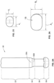
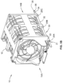
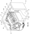
- FIG. 1A shows an implementation of a fan module 10 according to the present disclosure.
- FIG. 1B shows an implementation of an elongated lens 30 for use with the fan module 10 of FIG. 1A .
- the fan module 10 includes a housing 12 within which the fan (not shown) may be placed.
- the housing 12 includes a first end 14A and a second end 14B.
- the first end 14A of the housing 12 is positioned next to the light-emitting component (not shown).
- a light-emitting component can be integrated into a connector (not shown) or a connector board (not shown) for providing power and, optionally, control signals to the fan module 10.
- a removable cover plate 16 is coupled to the second end 14B of the housing 12 to protect the fan during use.
- the cover plate 16 generally forms a grid that includes a plurality of apertures 18.
- the apertures 18 allow air to flow through the housing 12.
- the housing 12 also includes one or more lens mount apertures 20A and 20B.
- the lens mount apertures 20A, 20B are sized to receive the elongated lens 30 and hold the elongated lens 30 within the housing 12. When the elongated lens 30 is integrated into the housing 12, at least a portion of the elongated lens 30 is disposed within the lens mount apertures 20A, 20B.
- the elongated lens 30 generally includes a body portion 32, a transition region 34, a neck portion 36, and a head portion 38.
- the transition region 34 is positioned between the body portion 32 and the neck portion 36.
- the neck portion 36 is positioned between the transition region 34 and the head portion 38.
- Each of these portions is sized so that the portions fit through the lens mount apertures 20A, 20B.
- the elongated lens 30 can also have a rotation-locking feature 31.
- the rotation-locking feature 31 is configured prevent the elongated lens 30 from rotating relative to the housing 12 once the elongated lens 30 is integrated into the housing 12.
- the rotation-locking feature 31 includes a radially-extending projection 33. When the elongated lens 30 is integrated into the housing 12, the radially-extending projection 33 of the rotation-locking feature 31 is positioned within a slot or aperture defined by the housing 12, which prevents rotation of the elongated lens 30.
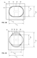
- FIG. 2A and FIG. 2B show details of the structure of the elongated lens 30.
- Both the body portion 32 and the neck portion 36 are generally circular.
- the diameter of the body portion 32 is generally larger than the diameter of the neck portion 36.
- the diameter of the transition region 34 decreases between the body portion 32 and the neck portion 36.
- a first end 35A of the transition region 34 is adjacent to the body portion 32. At the first end 35A, the diameter of the transition region 34 is generally equal to the diameter of the body portion 32. A second end 35B of the transition region 34 is adjacent to the neck portion 36. At the second end 35B, the diameter of the transition region 34 is generally equal to the diameter of the neck portion 36. Between these two ends 35A, 35B, the diameter of the transition region 34 decreases from the diameter of the body portion 32 to the diameter of the neck portion 36. This decrease can be linear or non-linear. The decrease can also be provided in a stepped fashion.
- the head portion 38 of the elongated lens 30 generally has an oblong shape with at least two different dimensions. As shown in FIG. 2B , the head portion 38 can have a generally oval shape with a larger dimension A L and a smaller dimension B L . Dimension A L of the head portion 38 can be the same or different than the diameter of the body portion 32. Similarly, dimension B L of the head portion 38 can be the same or different than the diameter of the neck portion 36. These different dimensions can be leveraged to lock the elongated lens 30 in place as described below in FIGs. 3A-3C
- At least one of the apertures 18, e.g., a first one of the apertures 18, in the cover plate 16 has an oblong shape.
- This oblong shape of the aperture 18 generally corresponds to the oblong shape of the head portion 38 of the elongated lens. That is, the aperture 18 has a larger dimension A A and a smaller dimension B A that are larger than A L and B L , respectively.
- dimension A L of the head portion 38 is aligned with dimension A A of the aperture 18.
- the head portion 38 is able to pass through the aperture 18.
- the cover plate 16 can be rotated relative to the elongated lens 30. For example, as shown in FIG. 3C , the cover plate 16 can be rotated 90 degrees. The result is that dimension A L of the head portion 38 is aligned with dimension B A of the aperture 18. Thus, the head portion 38 cannot pass back through the aperture 18 because dimension A L is larger than dimension B A . Further, by configuring at least a portion of the transition region 34 to have a dimension larger than dimension B A , further motion of the elongated lens 30 through the aperture 18 is prevented as well.
- dimension A L can be between about 3 millimeters and about 5 millimeters, or about 4.2 millimeters.
- Dimension B L can be between about 2 millimeters and about 4 millimeters, or about 3 millimeters.
- a ratio of dimension A L to dimension B L can be about 4.2:3.
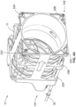
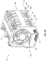
- FIGs. 4A-4C illustrate in more detail the integration of the elongated lens 30 into the housing 12 when viewing the second end 14B of the housing 12.
- the cover plate 16 is not attached to the housing 12.
- the elongated lens 30 is inserted into the housing 12 so as to pass through the lens mount apertures 20A and 20B.
- the elongated lens 30 is inserted further into the housing 12 so as to also pass through lens mount aperture 20C, and the cover plate 16 is positioned in a first orientation relative to the head portion 38.
- the cover plate 16 is positioned in this first orientation, the large dimension of the head portion 38 is aligned with the large dimension of the aperture 18.
- the head portion 38 can thus pass through the aperture 18, similar to the configuration illustrated in FIG. 3B .
- the elongated lens 30 is first inserted through the lens mount apertures 20A and 20B.
- the cover plate 16 can subsequently be positioned adjacent to the housing 12 so that the elongated lens 30 is inserted into the aperture 18.
- the cover plate 16 can initially be positioned adjacent to the housing 12, and the elongated lens 30 can then be inserted through the lens mount apertures 20A, 20B and the aperture 18.
- FIG. 4A also illustrates fasteners 22A, 22B, and 22C that can be inserted through fastener apertures in the housing 12.
- FIG. 4B illustrates fasteners 22A and 22B.
- Fastener 22C is not visible in FIG. 4B as the cover plate 16 is positioned in front of fastener 22C.
- the fasteners 22A-22C are configured to extend through the fastener apertures in the housing 12 and through fastener apertures in the cover plate 16 to secure the cover plate 16 to the housing 12. Any number of fasteners can be used. For example, when the housing 12 has a square or rectangular cross-section, the housing 12 may include three fastener apertures defined in the housing 12.
- the head portion 38 of the elongated lens 30 may be located adjacent to the fourth corner of the housing 12 when the elongated lens 30 is coupled to the housing 12.
- the cover plate 16 has three corresponding fastener apertures that align with the fastener apertures in the housing 12. The fasteners 22A-22C can then be inserted through the fastener apertures in the housing 12 and the cover plate 16.
- Other implementations may use any number of fasteners and fastener apertures.
- the housing 12 may include bosses extending from the housing 12 instead of or in addition to the fasteners 22A-22C and the fastener apertures.
- the bosses can extend from the housing 12 in the same direction that the head portion 38 of the elongated lens 30 extends through the aperture 18.
- the bosses can be used to secure the cover plate 16 to the housing 12 by mating with corresponding depressions or shafts (not shown) that are defined in the cover plate 16.
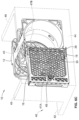
- the cover plate 16 can be rotated about 90 degrees to a second orientation relative to the head portion 38, as illustrated in FIG. 4C .
- this orientation the large dimension of the head portion 38 is aligned with the small dimension of the aperture 18. Because of this, the elongated lens 30 cannot be pulled back through the aperture 18.
- This second orientation of the cover plate 16 in FIG. 4C is the same as the orientation of the cover plate 16 in FIG. 3C .
- the elongated lens 30 can be locked into place with the head portion 38 extending out of the aperture 18.
- the fasteners 22A-22C can be inserted through the apertures in the housing 12 and the cover plate 16 to secure the cover plate 16 to the housing 12.
- the fasteners 22A-22C thus aid in preventing rotation of the cover plate 16 relative to the housing 12 once the fan module 10 and the elongated lens 30 are assembled.
- the cover plate 16 can be pressed into place such that the bosses of the housing 12 extend into the corresponding depressions or shafts of the cover plate 16. Once the cover plate 16 is secured to the housing 12, the fan module 10 can be installed into a computing device.
- the head portion can generally be any type of oblong shape, as long as the head portion has one larger dimension and one smaller dimension.
- the head could have a diamond shape, an elliptical shape, a rectangular shape, a rectilinear shape, a triangular shape, an egg shape, etc.
- the shape of the head portion could be a combination of multiple shapes, such as half-diamond and half-elliptical.
- the apertures of the cover plate can similarly have any shape so long as the aperture has: (i) a large dimension that is greater than both dimensions of the head portion, and (ii) a small dimension that is less than the large dimension of the head portion and greater than the smaller dimension of the head portion.
- the shapes of the apertures in the cover plate need not correspond with the shape of the head portion.
- the apertures in the cover plate may have a rectangular shape, while the head portion has an oval shape.
- the elongated lens will lock into place due to the relative alignment of the head portion and the cover plate.
- not all apertures in the cover plate need to be designed in this manner. Rather, the cover plate only needs to have a single aperture with the required dimensions. Any aperture that the head portion of the elongated lens will not extend through during operation can have any shape or configuration.
- the elongated lens can also have a variety of different relative dimensions between the body portion, the transition region, the neck portion, and the head portion.
- the diameters of the body portion, the transition region, and the neck portion may be dictated by the dimensions of the housing, the lens mount apertures, or other structural features of the housing or the cover plate not discussed herein.
- the body portion, the transition region, and the neck portion can have any suitable diameter, so long as those portions of the elongated lens do not interfere with the ability of the head portion to selectively pass through one of the apertures of the cover plate.
- the diameter of the body portion is greater than the smaller dimension of the apertures. The body portion is thus prevented from passing through the apertures in this implementation.
- the diameter of the neck portion is less than or equal to the smaller dimension of the apertures. The neck portion is thus permitted to pass through the apertures in this implementation.
- the length of the entire lens can between about 100 millimeters and about 150 millimeters, between about 120 millimeters and about 140 millimeters, between about 135 and about 140 millimeters, or about 138 millimeters.
- the distance between the rotation-locking feature and the border between the neck portion and the head portion can be between about 100 millimeters and about 150 millimeters.
- the thickness of the rotation-locking feature in an axial direction can be less than about 5 millimeters, less than about 3 millimeters, or about 1 millimeter.
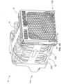
- FIGs. 5A-5D illustrate in more detail the integration of the elongated lens 30 into the housing 12 when viewing the first end 14A of the housing 12.
- the elongated lens 30 is inserted into the housing 12 so as to pass through lens mount apertures 20A and 20B.
- the elongated lens is inserted further into the housing 12 so as to also pass through lens mount aperture 20C until the head portion 38 extends past the second end 14B of the housing 12.
- the radially-extending projection 33 of the rotation locking-locking feature 31 is positioned within a slot defined in the housing 12 above the lens mount aperture 20A. This prevents the elongated lens 30 from rotating within the lens mount apertures 20A, 20B, and 20C relative to the housing 12. In some implementations, the rotation-locking feature 31 also prevents the elongated lens 30 from passing through the lens mount apertures 20A, 20B, and 20C any further.
- other components such as a fan connector 37 or a cable cover 39 can be coupled to the housing 12.
- the portion of the elongated lens 30 extending from lens mount aperture 20A toward the first end 14A of the housing can be inserted into these other components so as to lock the elongated lens 30 into place from the first end 14A of the housing 12.
- the fan connector 37 can be used control the operation of the fan, and produce the light that is transmitted using the elongated lens 30.
- the cable cover 39 can be used to route any cables or wires necessary for the operation of the fan.
- the assembly fixture 40 has a fixture body that generally includes a base plate 42, a first wall 44, a second wall 46, and a third wall 49.
- the first wall 44, the second wall 46, and the third wall 49 are coupled to edges of the base plate 42 and extend upwards at an angle of about 90 degrees.
- the second wall 46 and the third wall 49 are generally parallel to each other.
- the first wall 44 is positioned at an angle relative to both the second wall 46 and the third wall 49 of about 90 degrees.
- the assembly fixture 40 further includes a first alignment guide 41 extending from the base plate 42.
- the first alignment guide 41 is generally parallel with the second wall 46 and the third wall 49.
- the base plate 42, the first alignment guide 41, and the second wall 46 define a channel into which the fan module 10 may be placed during assembly.
- the assembly fixture 40 also includes a second alignment guide 43 extending from the third wall 49 toward the second wall 46.
- the second alignment guide 43 is spaced apart a distance from the first wall 44 that is generally equal to a thickness of the cover plate 16.
- the first alignment guide 41 is also spaced apart from the first wall 44 a distance generally equal to the thickness of the cover plate 16.
- the base plate 42, the first wall 44, the third wall 49, the first alignment guide 41, and the second alignment guide 43 thereby define a space into which the cover plate 16 may be placed during assembly.
- the cover plate 16 When placed in the assembly fixture 40, the cover plate 16 extends a distance from the third wall 49 such that at least a portion of the cover plate 16 is positioned between the first wall 44 and the fan module 10. The fan module 10 is thus prevented from being placed flush against the first wall 44, but rather is spaced a distance apart from the first wall 44.
- the assembly fixture 40 may also include further alignment guides.
- the assembly fixture 40 may include one or more projections 50A and 50B extending from the first wall 44 that assist in positioning the cover plate 16 during the assembly process.
- a top view of the fan module 10 and the cover plate 16 when both are placed into the assembly fixture 40 is shown in FIG. 6A .
- the assembly fixture 40 also includes a fixture opening.
- the fixture opening can have a circuitous shape, such as an arch.
- the fixture opening comprises an elongated aperture 45 that is defined in the first wall 44.
- the elongated aperture 45 has a first end 47A and a second end 47B.
- This elongated aperture 45 is sized so that a protuberance 48 coupled to the cover plate 16 can be inserted through the elongated aperture 45.
- the protuberance 48 can be removably coupled to the cover plate 16, or can be permanently coupled to the cover plate 16. To begin the assembly process, the cover plate 16 is placed against the first wall 44 in the orientation.
- FIG. 6B shows a perspective view of the assembly fixture 40 to illustrate the protuberance 48 extending through the elongated aperture 45.
- FIG. 6C shows the assembly fixture 40 as transparent to better illustrate the relative position of the components from the front.
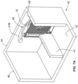
- FIGs. 7A-7D showing the process of assembling the fan module 10 and the cover plate 16 using the assembly fixture 40.
- the cover plate 16 can be placed into the assembly fixture 40.
- the cover plate 16 is positioned in the first orientation, at an angle of about 90 degrees relative to its final position when coupled to the housing 12 of the fan module 10.
- the housing 12 can be placed into the assembly fixture 40 as shown in FIG. 7B .
- the housing 12 with the integrated elongated lens 30 is placed into the space of the assembly fixture 40 defined between the second wall 46 and the first alignment guide 41.
- the head portion of the elongated lens 30 extends past the second end 14B of the housing 12.
- the assembly fixture 40 is dimensioned such that the head portion of the elongated lens 30 is aligned with an aperture in the cover plate 16. Because the cover plate 16 is positioned in the first orientation, the large dimension of the head portion of the elongated lens 30 will be aligned with the large dimension of the aperture. Consequently, the head portion of the elongated lens 30 will be able to pass through the large dimension of the aperture in the cover plate.
- the cover plate 16 can then be caused to rotate relative to the housing 12 by moving the protuberance 48 ( FIGs. 6A-6C ) in a curved path from the first end 47A of the elongated aperture 45 to the second end 47B of the elongated aperture 45.
- This movement causes the cover plate 16 to rotate about an axis that is generally coaxial with the elongated lens 30.
- the cover plate 16 is rotated until it is aligned with the housing 12, as shown in FIG. 7D .
- the cover plate 16 is positioned in the second orientation. In the second orientation, the large dimension of the head portion of the elongated lens 30 is aligned with the small dimension of the aperture 18. Because of this alignment, the elongated lens 30 cannot be pulled back through the aperture in the cover plate 16.
- the movement of the protuberance 48 also causes the fastener apertures in the housing 12 to align with the fastener apertures in the cover plate 16.
- the fasteners can be inserted through the fastener apertures in the housing 12 and the cover plate 16 to secure the cover plate 16 to the housing 12, thereby locking rotation of the cover plate 16 relative to the head portion of the elongated lens 30. While FIG. 7D illustrates only two fasteners 22A and 22C, any number of fasteners can be used to secure the cover plate 16 to the housing 12.
Landscapes
- Engineering & Computer Science (AREA)
- General Engineering & Computer Science (AREA)
- Mechanical Engineering (AREA)
- Physics & Mathematics (AREA)
- Microelectronics & Electronic Packaging (AREA)
- Optics & Photonics (AREA)
- General Physics & Mathematics (AREA)
- Thermal Sciences (AREA)
- Cooling Or The Like Of Electrical Apparatus (AREA)
- Lens Barrels (AREA)
- Mounting Components In General For Electric Apparatus (AREA)
- Transforming Electric Information Into Light Information (AREA)
- Non-Portable Lighting Devices Or Systems Thereof (AREA)
Description
- The present disclosure relates generally to fan modules with lenses for focusing light, and more particularly, to a lens that can be secured to a fan module.
- Components used in electronic devices or computing systems can generate large amounts of heat during operation. In such devices and systems, a fan module can be used to generate air flow to help carry away the generated heat. In certain configurations, a light-emitting component can be included in these devices or systems to communicate a status of the fan module to a technician. However, because of space limitations, the fan module may be needed to be placed between the light-emitting component and an area of the device or system visible to the technician. In these situations, an elongated lens can be used to transmit the emitted light to a more convenient viewing location. Specifically, the elongated lens can be integrated into the fan module. However, typical methods for integrating an elongated lens into a fan module have a high risk of damaging the elongated lens and degrading performance. For example, an elongated lens is typically secured within a fan module using screw-on lens caps. Such lens caps not only reduce the intensity of the transmitted light, but can cause fracture of the elongated lens during assembly. The present disclosure is directed to solving these and other problems.
US2016/0157380 discloses a removable fan tray and serves as basis for the preamble of claim 1.US6045249 discloses the combination of a light pipe and a face plate having an opening to receive the light pipe.JP2014235787 US2003026074 discloses a cooling fan apparatus that includes a plastic housing and an electric fan.US5481440 discloses a circuit pack that has a flat circuit board and a flat apertured face plate mounted at substantially right angles to the board. - According to examples of the present disclosure, a fan module with an integrated elongated lens is provided. The fan module includes a housing in which a fan may be disposed, and a cover plate that partially covers an opening in the housing. An elongated lens is included, which can be used to direct and focus light emitted by a light-emitting device. The elongated lens can be inserted through lens mount apertures in the housing of the fan module.
- The cover plate forms a grid that has a plurality of apertures, and is located at an end of the fan module opposite the light-emitting device. The elongated lens can be configured to extend through one of the apertures in the cover plate. A head portion of the elongated lens and at least one of the apertures in the cover plate are dimensioned to selectively pass through the aperture. When the cover plate is in a first orientation relative to the head portion, the head portion can pass through the aperture. When the cover plate is in a second orientation relative to the head portion, the head portion is prevented from passing through the aperture.
- The head portion of the elongated lens has an oblong shape with a first dimension and a second dimension. The aperture in the cover plate through which the head portion passes has a corresponding oblong shape with a first dimension and a second dimension. Generally, the first dimension of the head portion is less than the first dimension of the aperture but greater than the second dimension. The second dimension of the head portion is less than both the first dimension and the second dimension of the aperture.
- When the cover plate is in the first orientation relative to the head portion, the first dimension of the head portion is aligned with the first dimension of the aperture. Because the first dimension of the head portion is less than the first dimension of the aperture, the head portion can pass through the aperture. The cover plate can then be rotated about 90 degrees to the second orientation. In the second orientation, the first dimension of the head portion is aligned with the second dimension of the aperture. Because the first dimension of the head portion is greater than the second dimension of the aperture, the head portion cannot pass back through the aperture. By rotating the cover plate from a first orientation to a second orientation relative to the head portion of the elongated lens, the head portion is secured to the cover plate and is locked in place.
- The above summary is not intended to represent each embodiment or every aspect of the present disclosure. Rather, the foregoing summary merely provides an example of some of the novel aspects and features set forth herein. The above features and advantages, and other features and advantages of the present disclosure, will be readily apparent from the following detailed description of representative embodiments and modes for carrying out the present invention, when taken in connection with the accompanying drawings and the appended claims.
- The invention is defined by the appended independent claim.
- Further particular and preferred aspects of the present invention are set out in the accompanying dependent claims.
- The disclosure will be better understood from the following description of exemplary embodiments together with reference to the accompanying drawings.
-
FIG. 1A is a perspective view of a fan module according to some aspects of the present disclosure; -
FIG. 1B is a perspective view of an elongated lens for use with the fan module ofFIG. 1A , according to some aspects of the present disclosure; -
FIG. 2A is a cross-sectional view of the elongated lens ofFIG. 1B , according to some aspects of the present disclosure; -
FIG. 2B is an end elevation view of a head portion of the elongated lens ofFIG. 1B , according to some aspects of the present disclosure; -
FIG. 3A is an end elevation view of an aperture in a cover plate of the fan module ofFIG. 1A , according to some aspects of the present disclosure; -
FIG. 3B is an end elevation view of the aperture ofFIG. 3A in a first orientation relative to the head portion of the elongated lens ofFIG. 1B , according to some aspects of the present disclosure; -
FIG. 3C is an end elevation view of the aperture ofFIG. 3A in a second orientation relative to the head portion of the elongated lens ofFIG. 1B , according to some aspects of the present disclosure; -
FIG. 4A is a perspective view of a first end of the fan module ofFIG. 1A illustrating initial insertion of the elongated lens ofFIG. 1B , according to some aspects of the present disclosure; -
FIG. 4B is a perspective view of the first end of the fan module ofFIG. 1A with the cover plate in a first orientation relative to the head portion of the elongated lens ofFIG. 1B , according to some aspects of the present disclosure; -
FIG. 4C is a perspective view of the first end of the fan module ofFIG. 1A with the cover plate in a second orientation relative to the head portion of the elongated lens ofFIG. 1B , according to some aspects of the present disclosure; -
FIG. 5A is a perspective view of a second end of the fan module ofFIG. 1A illustrating initial insertion of the elongated lens ofFIG. 1B , according to some aspects of the present disclosure; -
FIG. 5B is perspective view of the second end of the fan module ofFIG. 1A illustrating further insertion of the elongated lens ofFIG. 1B , according to some aspects of the present disclosure; -
FIG. 5C is an enlarged perspective view of the elongated lens ofFIG. 1B being inserted into the fan module ofFIG. 1A , according to some aspects of the present disclosure; -
FIG. 5D is a perspective view of the second end of the fan module ofFIG. 1A illustrating a fan connector and a cable cover being attached to the fan module, according to some aspects of the present disclosure; -
FIG. 6A is a top plan view of an assembly fixture for assembling the fan module ofFIG. 1A and the elongated lens ofFIG. 1B , according to some aspects of the present disclosure; -
FIG. 6B is a perspective view of the assembly fixture ofFIG. 6A , according to some aspects of the present disclosure; and -
FIG. 6C is a partially transparent perspective view of the assembly fixture ofFIG. 6A , according to some aspects of the present disclosure; -
FIG. 7A is a perspective view of the cover plate of the fan module ofFIG. 1A being placed into the assembly fixture ofFIG. 6A in a first orientation, according to some aspects of the present disclosure; -
FIG. 7B is a perspective view of the housing of the fan module ofFIG. 1A being placed into the assembly fixture ofFIG. 6A , according to some aspects of the present disclosure; -
FIG. 7C is a perspective view of the cover plate of the fan module ofFIG. 1A being rotated from the first orientation to a second orientation, according to some aspects of the present disclosure; and -
FIG. 7D is a perspective view of the cover plate of the fan module ofFIG. 1A being positioned in the second orientation, according to some aspects of the present disclosure. - The present disclosure is susceptible to various modifications and alternative forms. Some representative embodiments have been shown by way of example in the drawings and will be described in detail herein. It should be understood, however, that the invention is not intended to be limited to the particular forms disclosed. Rather, the disclosure is to cover all modifications, equivalents, and alternatives falling within the spirit and scope of the invention as defined by the appended claims.
- The present inventions can be embodied in many different forms. Representative embodiments are shown in the drawings, and will herein be described in detail. The present disclosure is an example or illustration of the principles of the present disclosure, and is not intended to limit the broad aspects of the disclosure to the embodiments illustrated. To that extent, elements, and limitations that are disclosed, for example, in the Abstract, Summary, and Detailed Description sections, but not explicitly set forth in the claims, should not be incorporated into the claims, singly or collectively, by implication, inference, or otherwise. For purposes of the present detailed description, unless specifically disclaimed, the singular includes the plural and vice versa; and the word "including" means "including without limitation." Moreover, words of approximation, such as "about," "almost," "substantially," "approximately," and the like, can be used herein to mean "at," "near," or "nearly at," or "within 3-5% of," or "within acceptable manufacturing tolerances," or any logical combination thereof, for example.
- As noted above it, is challenging to integrate elongated lenses into fan modules. The present disclosure provides new designs for fan modules with integrated elongated lens, which address the limitations of conventional designs. In particular, the fan module and the elongated lens are configured such that a head portion of the elongated lens can selectively pass through an aperture in a cover plate of the fan module. The aperture in the cover plate has an oblong shape with a first dimension and a second dimension. Similarly, the head portion of the elongated lens also has an oblong shape with a first dimension and a second dimension, where the first dimension of the head portion is less than the first dimension of the aperture but greater than the second dimension. During assembly of the fan module, the cover plate can be rotated relative to the head portion of the elongated lens. This action locks the head portion of the elongated lens in place within the fan module. In this way, the elongated lens is secured within the fan module without the need for lens caps, thereby reducing the risk of fractures and improving light transmission.
-
FIG. 1A shows an implementation of afan module 10 according to the present disclosure.FIG. 1B shows an implementation of anelongated lens 30 for use with thefan module 10 ofFIG. 1A . As shown inFIG. 1A , thefan module 10 includes ahousing 12 within which the fan (not shown) may be placed. Thehousing 12 includes afirst end 14A and asecond end 14B. Thefirst end 14A of thehousing 12 is positioned next to the light-emitting component (not shown). Such a light-emitting component can be integrated into a connector (not shown) or a connector board (not shown) for providing power and, optionally, control signals to thefan module 10. - A
removable cover plate 16 is coupled to thesecond end 14B of thehousing 12 to protect the fan during use. In the exemplary configuration ofFIG. 1A , thecover plate 16 generally forms a grid that includes a plurality ofapertures 18. However, the present disclosure contemplates that any other arrangement ofapertures 18 can be used. Theapertures 18 allow air to flow through thehousing 12. Thehousing 12 also includes one or morelens mount apertures lens mount apertures elongated lens 30 and hold theelongated lens 30 within thehousing 12. When theelongated lens 30 is integrated into thehousing 12, at least a portion of theelongated lens 30 is disposed within thelens mount apertures - In
FIG. 1B , theelongated lens 30 generally includes abody portion 32, atransition region 34, aneck portion 36, and ahead portion 38. Thetransition region 34 is positioned between thebody portion 32 and theneck portion 36. Theneck portion 36 is positioned between thetransition region 34 and thehead portion 38. Each of these portions is sized so that the portions fit through thelens mount apertures elongated lens 30 is integrated into thefan module 10, at least thehead portion 38 is configured to extend past thesecond end 14B. Thehead portion 38 can then pass through one of theapertures 18 of thecover plate 16. Theelongated lens 30 thus transmits emitted light from thefirst end 14A to thesecond end 14B. - The
elongated lens 30 can also have a rotation-lockingfeature 31. The rotation-lockingfeature 31 is configured prevent theelongated lens 30 from rotating relative to thehousing 12 once theelongated lens 30 is integrated into thehousing 12. In some implementations, the rotation-lockingfeature 31 includes a radially-extendingprojection 33. When theelongated lens 30 is integrated into thehousing 12, the radially-extendingprojection 33 of the rotation-lockingfeature 31 is positioned within a slot or aperture defined by thehousing 12, which prevents rotation of theelongated lens 30. -
FIG. 2A and FIG. 2B show details of the structure of theelongated lens 30. Both thebody portion 32 and theneck portion 36 are generally circular. The diameter of thebody portion 32 is generally larger than the diameter of theneck portion 36. The diameter of thetransition region 34 decreases between thebody portion 32 and theneck portion 36. - A
first end 35A of thetransition region 34 is adjacent to thebody portion 32. At thefirst end 35A, the diameter of thetransition region 34 is generally equal to the diameter of thebody portion 32. Asecond end 35B of thetransition region 34 is adjacent to theneck portion 36. At thesecond end 35B, the diameter of thetransition region 34 is generally equal to the diameter of theneck portion 36. Between these twoends transition region 34 decreases from the diameter of thebody portion 32 to the diameter of theneck portion 36. This decrease can be linear or non-linear. The decrease can also be provided in a stepped fashion. - The
head portion 38 of theelongated lens 30 generally has an oblong shape with at least two different dimensions. As shown inFIG. 2B , thehead portion 38 can have a generally oval shape with a larger dimension AL and a smaller dimension BL. Dimension AL of thehead portion 38 can be the same or different than the diameter of thebody portion 32. Similarly, dimension BL of thehead portion 38 can be the same or different than the diameter of theneck portion 36. These different dimensions can be leveraged to lock theelongated lens 30 in place as described below inFIGs. 3A-3C - As shown in
FIG. 3A , at least one of theapertures 18, e.g., a first one of theapertures 18, in thecover plate 16 has an oblong shape. This oblong shape of theaperture 18 generally corresponds to the oblong shape of thehead portion 38 of the elongated lens. That is, theaperture 18 has a larger dimension AA and a smaller dimension BA that are larger than AL and BL, respectively. During assembly, as shown inFIG. 3B , dimension AL of thehead portion 38 is aligned with dimension AA of theaperture 18. Thus, thehead portion 38 is able to pass through theaperture 18. - To lock the elongated lens in place, the
cover plate 16 can be rotated relative to theelongated lens 30. For example, as shown inFIG. 3C , thecover plate 16 can be rotated 90 degrees. The result is that dimension AL of thehead portion 38 is aligned with dimension BA of theaperture 18. Thus, thehead portion 38 cannot pass back through theaperture 18 because dimension AL is larger than dimension BA. Further, by configuring at least a portion of thetransition region 34 to have a dimension larger than dimension BA, further motion of theelongated lens 30 through theaperture 18 is prevented as well. In some implementations, dimension AL can be between about 3 millimeters and about 5 millimeters, or about 4.2 millimeters. Dimension BL can be between about 2 millimeters and about 4 millimeters, or about 3 millimeters. In some implementations, a ratio of dimension AL to dimension BL can be about 4.2:3. -
FIGs. 4A-4C illustrate in more detail the integration of theelongated lens 30 into thehousing 12 when viewing thesecond end 14B of thehousing 12. Initially, as shown inFIG. 4A , thecover plate 16 is not attached to thehousing 12. Theelongated lens 30 is inserted into thehousing 12 so as to pass through thelens mount apertures FIG. 4B , theelongated lens 30 is inserted further into thehousing 12 so as to also pass throughlens mount aperture 20C, and thecover plate 16 is positioned in a first orientation relative to thehead portion 38. When thecover plate 16 is positioned in this first orientation, the large dimension of thehead portion 38 is aligned with the large dimension of theaperture 18. Thehead portion 38 can thus pass through theaperture 18, similar to the configuration illustrated inFIG. 3B . - In some implementations, the
elongated lens 30 is first inserted through thelens mount apertures cover plate 16 can subsequently be positioned adjacent to thehousing 12 so that theelongated lens 30 is inserted into theaperture 18. In other implementations, thecover plate 16 can initially be positioned adjacent to thehousing 12, and theelongated lens 30 can then be inserted through thelens mount apertures aperture 18. -
FIG. 4A also illustratesfasteners housing 12.FIG. 4B illustratesfasteners Fastener 22C is not visible inFIG. 4B as thecover plate 16 is positioned in front offastener 22C. Thefasteners 22A-22C are configured to extend through the fastener apertures in thehousing 12 and through fastener apertures in thecover plate 16 to secure thecover plate 16 to thehousing 12. Any number of fasteners can be used. For example, when thehousing 12 has a square or rectangular cross-section, thehousing 12 may include three fastener apertures defined in thehousing 12. Thehead portion 38 of theelongated lens 30 may be located adjacent to the fourth corner of thehousing 12 when theelongated lens 30 is coupled to thehousing 12. In this implementation, thecover plate 16 has three corresponding fastener apertures that align with the fastener apertures in thehousing 12. Thefasteners 22A-22C can then be inserted through the fastener apertures in thehousing 12 and thecover plate 16. Other implementations may use any number of fasteners and fastener apertures. - In other implementations, the
housing 12 may include bosses extending from thehousing 12 instead of or in addition to thefasteners 22A-22C and the fastener apertures. The bosses can extend from thehousing 12 in the same direction that thehead portion 38 of theelongated lens 30 extends through theaperture 18. The bosses can be used to secure thecover plate 16 to thehousing 12 by mating with corresponding depressions or shafts (not shown) that are defined in thecover plate 16. - Once the
elongated lens 30 has been inserted through thehousing 12 and theaperture 18, thecover plate 16 can be rotated about 90 degrees to a second orientation relative to thehead portion 38, as illustrated inFIG. 4C . In this orientation, the large dimension of thehead portion 38 is aligned with the small dimension of theaperture 18. Because of this, theelongated lens 30 cannot be pulled back through theaperture 18. This second orientation of thecover plate 16 inFIG. 4C is the same as the orientation of thecover plate 16 inFIG. 3C . Thus, theelongated lens 30 can be locked into place with thehead portion 38 extending out of theaperture 18. - After rotating the
cover plate 16 to the second orientation, thefasteners 22A-22C can be inserted through the apertures in thehousing 12 and thecover plate 16 to secure thecover plate 16 to thehousing 12. Thefasteners 22A-22C thus aid in preventing rotation of thecover plate 16 relative to thehousing 12 once thefan module 10 and theelongated lens 30 are assembled. In other implementations, thecover plate 16 can be pressed into place such that the bosses of thehousing 12 extend into the corresponding depressions or shafts of thecover plate 16. Once thecover plate 16 is secured to thehousing 12, thefan module 10 can be installed into a computing device. - Other shapes of the elongated lens and the apertures of the cover plate are contemplated. The head portion can generally be any type of oblong shape, as long as the head portion has one larger dimension and one smaller dimension. For example, the head could have a diamond shape, an elliptical shape, a rectangular shape, a rectilinear shape, a triangular shape, an egg shape, etc. The shape of the head portion could be a combination of multiple shapes, such as half-diamond and half-elliptical. The apertures of the cover plate can similarly have any shape so long as the aperture has: (i) a large dimension that is greater than both dimensions of the head portion, and (ii) a small dimension that is less than the large dimension of the head portion and greater than the smaller dimension of the head portion.
- In some implementations, the shapes of the apertures in the cover plate need not correspond with the shape of the head portion. For example, the apertures in the cover plate may have a rectangular shape, while the head portion has an oval shape. As long as the dimensions of the head portion and the aperture satisfy the relationships discuss herein, the elongated lens will lock into place due to the relative alignment of the head portion and the cover plate. Moreover, not all apertures in the cover plate need to be designed in this manner. Rather, the cover plate only needs to have a single aperture with the required dimensions. Any aperture that the head portion of the elongated lens will not extend through during operation can have any shape or configuration.
- The elongated lens can also have a variety of different relative dimensions between the body portion, the transition region, the neck portion, and the head portion. For example, the diameters of the body portion, the transition region, and the neck portion may be dictated by the dimensions of the housing, the lens mount apertures, or other structural features of the housing or the cover plate not discussed herein. Generally, the body portion, the transition region, and the neck portion can have any suitable diameter, so long as those portions of the elongated lens do not interfere with the ability of the head portion to selectively pass through one of the apertures of the cover plate.
- In some implementations, the diameter of the body portion is greater than the smaller dimension of the apertures. The body portion is thus prevented from passing through the apertures in this implementation. Similarly, in some implementations, the diameter of the neck portion is less than or equal to the smaller dimension of the apertures. The neck portion is thus permitted to pass through the apertures in this implementation.
- In some implementations, the length of the entire lens can between about 100 millimeters and about 150 millimeters, between about 120 millimeters and about 140 millimeters, between about 135 and about 140 millimeters, or about 138 millimeters. The distance between the rotation-locking feature and the border between the neck portion and the head portion can be between about 100 millimeters and about 150 millimeters. The thickness of the rotation-locking feature in an axial direction can be less than about 5 millimeters, less than about 3 millimeters, or about 1 millimeter.
-
FIGs. 5A-5D illustrate in more detail the integration of theelongated lens 30 into thehousing 12 when viewing thefirst end 14A of thehousing 12. Initially, as shown inFIG. 5A , theelongated lens 30 is inserted into thehousing 12 so as to pass throughlens mount apertures FIG. 5B , the elongated lens is inserted further into thehousing 12 so as to also pass throughlens mount aperture 20C until thehead portion 38 extends past thesecond end 14B of thehousing 12. - As shown in
FIG. 5C , once theelongated lens 30 is inserted fully into thehousing 12, the radially-extendingprojection 33 of the rotation locking-lockingfeature 31 is positioned within a slot defined in thehousing 12 above thelens mount aperture 20A. This prevents theelongated lens 30 from rotating within thelens mount apertures housing 12. In some implementations, the rotation-lockingfeature 31 also prevents theelongated lens 30 from passing through thelens mount apertures FIG. 5D , other components, such as afan connector 37 or acable cover 39 can be coupled to thehousing 12. The portion of theelongated lens 30 extending fromlens mount aperture 20A toward thefirst end 14A of the housing can be inserted into these other components so as to lock theelongated lens 30 into place from thefirst end 14A of thehousing 12. Thefan connector 37 can be used control the operation of the fan, and produce the light that is transmitted using theelongated lens 30. Thecable cover 39 can be used to route any cables or wires necessary for the operation of the fan. - Referring now to
FIGs. 6A-6C , anexemplary assembly fixture 40 is shown for facilitating assembly of thehousing 12 and thecover plate 16. Theassembly fixture 40 has a fixture body that generally includes abase plate 42, afirst wall 44, asecond wall 46, and athird wall 49. Thefirst wall 44, thesecond wall 46, and thethird wall 49 are coupled to edges of thebase plate 42 and extend upwards at an angle of about 90 degrees. Thesecond wall 46 and thethird wall 49 are generally parallel to each other. Thefirst wall 44 is positioned at an angle relative to both thesecond wall 46 and thethird wall 49 of about 90 degrees. Theassembly fixture 40 further includes afirst alignment guide 41 extending from thebase plate 42. Thefirst alignment guide 41 is generally parallel with thesecond wall 46 and thethird wall 49. Thebase plate 42, thefirst alignment guide 41, and thesecond wall 46 define a channel into which thefan module 10 may be placed during assembly. - The
assembly fixture 40 also includes asecond alignment guide 43 extending from thethird wall 49 toward thesecond wall 46. Thesecond alignment guide 43 is spaced apart a distance from thefirst wall 44 that is generally equal to a thickness of thecover plate 16. Thefirst alignment guide 41 is also spaced apart from the first wall 44 a distance generally equal to the thickness of thecover plate 16. Thebase plate 42, thefirst wall 44, thethird wall 49, thefirst alignment guide 41, and thesecond alignment guide 43 thereby define a space into which thecover plate 16 may be placed during assembly. When placed in theassembly fixture 40, thecover plate 16 extends a distance from thethird wall 49 such that at least a portion of thecover plate 16 is positioned between thefirst wall 44 and thefan module 10. Thefan module 10 is thus prevented from being placed flush against thefirst wall 44, but rather is spaced a distance apart from thefirst wall 44. - The
assembly fixture 40 may also include further alignment guides. For example, theassembly fixture 40 may include one ormore projections first wall 44 that assist in positioning thecover plate 16 during the assembly process. A top view of thefan module 10 and thecover plate 16 when both are placed into theassembly fixture 40 is shown inFIG. 6A . - The
assembly fixture 40 also includes a fixture opening. The fixture opening can have a circuitous shape, such as an arch. As shown inFIG. 6B , the fixture opening comprises anelongated aperture 45 that is defined in thefirst wall 44. Theelongated aperture 45 has afirst end 47A and asecond end 47B. Thiselongated aperture 45 is sized so that aprotuberance 48 coupled to thecover plate 16 can be inserted through theelongated aperture 45. Theprotuberance 48 can be removably coupled to thecover plate 16, or can be permanently coupled to thecover plate 16. To begin the assembly process, thecover plate 16 is placed against thefirst wall 44 in the orientation. In this orientation, theprotuberance 48 extends through theelongated aperture 45 at thefirst end 47A of theelongated aperture 45. Theprotuberance 48 extends all the way through theelongated aperture 45 to the side of thefirst wall 44 opposite of thefan module 10.FIG. 6B shows a perspective view of theassembly fixture 40 to illustrate theprotuberance 48 extending through theelongated aperture 45.FIG. 6C shows theassembly fixture 40 as transparent to better illustrate the relative position of the components from the front. -
FIGs. 7A-7D showing the process of assembling thefan module 10 and thecover plate 16 using theassembly fixture 40. First, as shown inFIG. 7A , thecover plate 16 can be placed into theassembly fixture 40. When thecover plate 16 is initially placed into theassembly fixture 40, thecover plate 16 is positioned in the first orientation, at an angle of about 90 degrees relative to its final position when coupled to thehousing 12 of thefan module 10. After theelongated lens 30 has been integrated into the housing 12 (as shown inFIGS. 4A-4C and5A-5D herein), thehousing 12 can be placed into theassembly fixture 40 as shown inFIG. 7B . Thehousing 12 with the integratedelongated lens 30 is placed into the space of theassembly fixture 40 defined between thesecond wall 46 and thefirst alignment guide 41. - When the
housing 12 is placed into theassembly fixture 40, the head portion of theelongated lens 30 extends past thesecond end 14B of thehousing 12. Theassembly fixture 40 is dimensioned such that the head portion of theelongated lens 30 is aligned with an aperture in thecover plate 16. Because thecover plate 16 is positioned in the first orientation, the large dimension of the head portion of theelongated lens 30 will be aligned with the large dimension of the aperture. Consequently, the head portion of theelongated lens 30 will be able to pass through the large dimension of the aperture in the cover plate. By placing thehousing 12 into theassembly fixture 40 after placing thecover plate 16 into theassembly fixture 40, the head portion of theelongated lens 30 passes through the aperture in thecover plate 16. - As shown in
FIG. 7C , thecover plate 16 can then be caused to rotate relative to thehousing 12 by moving the protuberance 48 (FIGs. 6A-6C ) in a curved path from thefirst end 47A of theelongated aperture 45 to thesecond end 47B of theelongated aperture 45. This movement causes thecover plate 16 to rotate about an axis that is generally coaxial with theelongated lens 30. Thecover plate 16 is rotated until it is aligned with thehousing 12, as shown inFIG. 7D . InFIG. 7D , thecover plate 16 is positioned in the second orientation. In the second orientation, the large dimension of the head portion of theelongated lens 30 is aligned with the small dimension of theaperture 18. Because of this alignment, theelongated lens 30 cannot be pulled back through the aperture in thecover plate 16. - The movement of the
protuberance 48 also causes the fastener apertures in thehousing 12 to align with the fastener apertures in thecover plate 16. Once in the second orientation, the fasteners can be inserted through the fastener apertures in thehousing 12 and thecover plate 16 to secure thecover plate 16 to thehousing 12, thereby locking rotation of thecover plate 16 relative to the head portion of theelongated lens 30. WhileFIG. 7D illustrates only twofasteners cover plate 16 to thehousing 12. - Unless otherwise defined, all terms (including technical and scientific terms) used herein have the same meaning as commonly understood by one of ordinary skill in the art. Furthermore, terms, such as those defined in commonly used dictionaries, should be interpreted as having a meaning that is consistent with their meaning in the context of the relevant art, and will not be interpreted in an idealized or overly formal sense unless expressly so defined herein.
- Although the invention has been illustrated and described with respect to one or more implementations, equivalent alterations, and modifications will occur or be known to others skilled in the art upon the reading and understanding of this specification and the annexed drawings. In addition, while a particular feature of the invention may have been disclosed with respect to only one of several implementations, such feature may be combined with one or more other features of the other implementations as may be desired and advantageous for any given or particular application.
- Although particular embodiments have been described herein, it will be appreciated that the invention is not limited thereto and that many modifications and additions thereto may be made within the scope of the invention as defined in the appended claims.
Claims (8)
- An apparatus, comprising:a fan module (10) including a housing (12) and a cover plate (16) coupled to an end of the housing (12), the housing (12) adapted for a fan being placed within the housing (12), the housing (12) including a first end (14A) and a second end (14B), the cover plate (16) having a plurality of apertures (18); andan elongated lens (30) having a body portion (32), a transition region (34), a neck portion (36), and a head portion (38),wherein the transition region (34) is positioned between the body portion (32) and the neck portion (36), and the neck portion (36) is positioned between the transition region (34) and the head portion (38),wherein the body portion (32) has a first diameter and the neck portion (36) has a second diameter that is less than the first diameter,wherein both the body portion (32) and the neck portion (36) are generally circular, wherein the elongated lens (30) is configured to transmit light from the first end (14A) to the second end (14B), the apparatus being characterized in thatthe head portion (38) has a first oblong shape with a first dimension (AL) and a second dimension (BL) smaller than the first dimension (AL),wherein a first one of the plurality of apertures (18) has a second oblong shape with a first dimension (AA) and a second dimension (BA) smaller than the first dimension (AA),wherein the first dimension (AL) of the first oblong shape is less than the first dimension (AA) of the second oblong shape and greater than the second dimension (BA) of second oblong shape, and wherein the second dimension (BL) of the first oblong shape is less than the second dimension (BA) of second oblong shape,wherein the first dimension (AL) of the head portion (38) is equal to the first diameter of the body portion (32), and the second dimension (BL) of the head portion (38) is equal to the second diameter (BL) of the neck portion (36),wherein the first diameter of the body portion (32) is greater than the second dimension of the first one of the plurality of apertures (18), and the second diameter of the neck portion (36) is less than or equal to the second dimension of the first one of the plurality of apertures (18),wherein the first one of the plurality of apertures (18) and the head portion (38) are dimensioned to permit the head portion (38) to pass through the first one of the plurality of apertures (18) responsive to the cover plate (16) being positioned in a first orientation relative to the head portion (38), and to prevent the head portion (38) from passing through the first one of the plurality of apertures (18) responsive to the cover plate (16) being positioned in a second orientation relative to the head portion 38.
- The apparatus of claim 1, wherein the second orientation of the cover plate (16) is rotated about 90 degrees relative to the first orientation of the cover plate (16).
- The apparatus of claim 1, wherein when the cover plate (16) is positioned in the first orientation relative to the head portion (38), the first dimension (AL) of the head portion (38) is aligned with the first dimension (AA) of the first one of the plurality of apertures (18).
- The apparatus of claim 3, wherein when the cover plate (16) is positioned in the second orientation relative to the head portion (38), the first dimension (AL) of the head portion (38) is aligned with the second dimension (BA) of the first one of the plurality of apertures (18).
- The apparatus of any of claims 1-4, wherein at least a portion of the elongated lens (30) is coupled to the housing (12) of the fan module (10), and wherein the head portion (38) of the elongated lens (30) extends from the housing (12) of the fan module (10) in a first direction.
- The apparatus of claim 5, further comprising at least one fastener (22A) configured to extend through at least one housing fastener aperture defined by the housing (12) of the fan module (10) and a corresponding at least one cover plate fastener aperture defined by the cover plate (16), the at least one fastener (22A, 22B, 22C) configured to lock the cover plate (16) in the second orientation.
- The apparatus of any preceding claim, wherein the cover plate (16) includes a protuberance (48).
- The apparatus of claim 7, wherein the protuberance (48) is removably attached to the cover plate (16).
Applications Claiming Priority (1)
| Application Number | Priority Date | Filing Date | Title |
|---|---|---|---|
| US16/138,210 US10837453B2 (en) | 2018-09-21 | 2018-09-21 | Fan module with lockable lens |
Publications (2)
| Publication Number | Publication Date |
|---|---|
| EP3627200A1 EP3627200A1 (en) | 2020-03-25 |
| EP3627200B1 true EP3627200B1 (en) | 2023-06-21 |
Family
ID=65904190
Family Applications (1)
| Application Number | Title | Priority Date | Filing Date |
|---|---|---|---|
| EP19164361.8A Active EP3627200B1 (en) | 2018-09-21 | 2019-03-21 | Fan module with lockable lens |
Country Status (5)
| Country | Link |
|---|---|
| US (1) | US10837453B2 (en) |
| EP (1) | EP3627200B1 (en) |
| JP (1) | JP6727358B2 (en) |
| CN (1) | CN110939604B (en) |
| TW (1) | TWI676883B (en) |
Families Citing this family (3)
| Publication number | Priority date | Publication date | Assignee | Title |
|---|---|---|---|---|
| DE102018205300A1 (en) * | 2018-04-09 | 2019-10-10 | Ziehl-Abegg Se | Fan and inflow grille for a fan |
| TWI703273B (en) * | 2020-02-04 | 2020-09-01 | 奇鋐科技股份有限公司 | Fan engagement structure |
| US11661955B2 (en) | 2020-02-25 | 2023-05-30 | Asia Vital Components Co., Ltd. | Fan engagement structure |
Family Cites Families (12)
| Publication number | Priority date | Publication date | Assignee | Title |
|---|---|---|---|---|
| US5481440A (en) | 1993-12-27 | 1996-01-02 | At&T Corp. | Circuit pack with light pipes |
| US6045249A (en) | 1999-01-19 | 2000-04-04 | Lucent Technologies Inc. | Twist-in light pipe |
| US6690576B2 (en) | 2001-07-31 | 2004-02-10 | Hewlett Packard Development Company, L.P. | Externally mounted on-line replaceable fan module |
| JP4059318B2 (en) * | 2002-09-30 | 2008-03-12 | 本田技研工業株式会社 | Internal combustion engine cam chain fall-off prevention structure |
| CN2877939Y (en) * | 2006-03-01 | 2007-03-14 | 广达电脑股份有限公司 | Lead-free welding rework system |
| US7641441B2 (en) * | 2006-09-22 | 2010-01-05 | Inventec Corporation | Fan device |
| CN200961456Y (en) * | 2006-10-05 | 2007-10-17 | 王鹏 | Elevator self-locking device for sucking rod |
| TWI449840B (en) * | 2011-04-08 | 2014-08-21 | Delta Electronics Inc | Fan assembly and fan device thereof |
| US9253927B1 (en) * | 2012-09-28 | 2016-02-02 | Juniper Networks, Inc. | Removable fan tray |
| JP6209865B2 (en) | 2013-05-30 | 2017-10-11 | 東芝ライテック株式会社 | Vehicle lighting device |
| TWM478807U (en) | 2013-12-27 | 2014-05-21 | Accton Technology Corp | Object connection identification system |
| TWI602999B (en) * | 2016-10-11 | 2017-10-21 | 廣達電腦股份有限公司 | Computer device and its hot swappable fan module |
-
2018
- 2018-09-21 US US16/138,210 patent/US10837453B2/en active Active
- 2018-12-18 TW TW107145753A patent/TWI676883B/en active
-
2019
- 2019-01-07 CN CN201910011169.XA patent/CN110939604B/en active Active
- 2019-02-20 JP JP2019028608A patent/JP6727358B2/en active Active
- 2019-03-21 EP EP19164361.8A patent/EP3627200B1/en active Active
Also Published As
| Publication number | Publication date |
|---|---|
| TW202013122A (en) | 2020-04-01 |
| JP2020052387A (en) | 2020-04-02 |
| US10837453B2 (en) | 2020-11-17 |
| US20200096003A1 (en) | 2020-03-26 |
| JP6727358B2 (en) | 2020-07-22 |
| EP3627200A1 (en) | 2020-03-25 |
| CN110939604B (en) | 2022-01-14 |
| TWI676883B (en) | 2019-11-11 |
| CN110939604A (en) | 2020-03-31 |
Similar Documents
| Publication | Publication Date | Title |
|---|---|---|
| EP3627200B1 (en) | Fan module with lockable lens | |
| US10197242B2 (en) | Lens arrays and mountings | |
| ES2364695T3 (en) | ELECTRICAL PLUG CONNECTOR. | |
| US7942563B2 (en) | LED with light pipe assembly | |
| WO2017148228A1 (en) | Lighting device | |
| US9157612B2 (en) | Lighting assembly | |
| JP5820049B1 (en) | LED lighting device | |
| US20080145004A1 (en) | Communications device | |
| WO2014172610A2 (en) | Omni-directional led lamp | |
| CN111947064A (en) | Lamp fitting | |
| JP6029789B2 (en) | LED lighting device | |
| KR20110087712A (en) | Luminous element package and method for manufacturing the same | |
| WO2016197812A1 (en) | Top mounted and wall mounted compatible led lamp | |
| EP3015757B1 (en) | Lighting device | |
| CN111051766A (en) | Tool-free lighting fixing device | |
| JP5820048B1 (en) | LED lighting device | |
| CN213178260U (en) | Heat radiation structure and stage lamp | |
| CN217784897U (en) | Concatenation formula line lamp | |
| CN210069790U (en) | Emergency power supply box | |
| JP2016021371A (en) | LED lighting device | |
| WO2015182599A1 (en) | Led lighting apparatus | |
| TW202121763A (en) | Electrical connector cage assembly, electrical connector, and electronic apparatus | |
| JP2002190211A (en) | Luminaire | |
| JP2010105418A (en) | Lamp unit mounting structure |
Legal Events
| Date | Code | Title | Description |
|---|---|---|---|
| PUAI | Public reference made under article 153(3) epc to a published international application that has entered the european phase |
Free format text: ORIGINAL CODE: 0009012 |
|
| STAA | Information on the status of an ep patent application or granted ep patent |
Free format text: STATUS: THE APPLICATION HAS BEEN PUBLISHED |
|
| AK | Designated contracting states |
Kind code of ref document: A1 Designated state(s): AL AT BE BG CH CY CZ DE DK EE ES FI FR GB GR HR HU IE IS IT LI LT LU LV MC MK MT NL NO PL PT RO RS SE SI SK SM TR |
|
| AX | Request for extension of the european patent |
Extension state: BA ME |
|
| STAA | Information on the status of an ep patent application or granted ep patent |
Free format text: STATUS: REQUEST FOR EXAMINATION WAS MADE |
|
| 17P | Request for examination filed |
Effective date: 20200720 |
|
| RBV | Designated contracting states (corrected) |
Designated state(s): AL AT BE BG CH CY CZ DE DK EE ES FI FR GB GR HR HU IE IS IT LI LT LU LV MC MK MT NL NO PL PT RO RS SE SI SK SM TR |
|
| STAA | Information on the status of an ep patent application or granted ep patent |
Free format text: STATUS: EXAMINATION IS IN PROGRESS |
|
| 17Q | First examination report despatched |
Effective date: 20210802 |
|
| GRAP | Despatch of communication of intention to grant a patent |
Free format text: ORIGINAL CODE: EPIDOSNIGR1 |
|
| STAA | Information on the status of an ep patent application or granted ep patent |
Free format text: STATUS: GRANT OF PATENT IS INTENDED |
|
| INTG | Intention to grant announced |
Effective date: 20230208 |
|
| GRAS | Grant fee paid |
Free format text: ORIGINAL CODE: EPIDOSNIGR3 |
|
| GRAA | (expected) grant |
Free format text: ORIGINAL CODE: 0009210 |
|
| STAA | Information on the status of an ep patent application or granted ep patent |
Free format text: STATUS: THE PATENT HAS BEEN GRANTED |
|
| AK | Designated contracting states |
Kind code of ref document: B1 Designated state(s): AL AT BE BG CH CY CZ DE DK EE ES FI FR GB GR HR HU IE IS IT LI LT LU LV MC MK MT NL NO PL PT RO RS SE SI SK SM TR |
|
| REG | Reference to a national code |
Ref country code: CH Ref legal event code: EP |
|
| REG | Reference to a national code |
Ref country code: DE Ref legal event code: R096 Ref document number: 602019031237 Country of ref document: DE |
|
| REG | Reference to a national code |
Ref country code: AT Ref legal event code: REF Ref document number: 1581306 Country of ref document: AT Kind code of ref document: T Effective date: 20230715 |
|
| REG | Reference to a national code |
Ref country code: IE Ref legal event code: FG4D |
|
| REG | Reference to a national code |
Ref country code: LT Ref legal event code: MG9D |
|
| REG | Reference to a national code |
Ref country code: NL Ref legal event code: MP Effective date: 20230621 |
|
| PG25 | Lapsed in a contracting state [announced via postgrant information from national office to epo] |
Ref country code: SE Free format text: LAPSE BECAUSE OF FAILURE TO SUBMIT A TRANSLATION OF THE DESCRIPTION OR TO PAY THE FEE WITHIN THE PRESCRIBED TIME-LIMIT Effective date: 20230621 Ref country code: NO Free format text: LAPSE BECAUSE OF FAILURE TO SUBMIT A TRANSLATION OF THE DESCRIPTION OR TO PAY THE FEE WITHIN THE PRESCRIBED TIME-LIMIT Effective date: 20230921 |
|
| REG | Reference to a national code |
Ref country code: AT Ref legal event code: MK05 Ref document number: 1581306 Country of ref document: AT Kind code of ref document: T Effective date: 20230621 |
|
| PG25 | Lapsed in a contracting state [announced via postgrant information from national office to epo] |
Ref country code: RS Free format text: LAPSE BECAUSE OF FAILURE TO SUBMIT A TRANSLATION OF THE DESCRIPTION OR TO PAY THE FEE WITHIN THE PRESCRIBED TIME-LIMIT Effective date: 20230621 Ref country code: NL Free format text: LAPSE BECAUSE OF FAILURE TO SUBMIT A TRANSLATION OF THE DESCRIPTION OR TO PAY THE FEE WITHIN THE PRESCRIBED TIME-LIMIT Effective date: 20230621 Ref country code: LV Free format text: LAPSE BECAUSE OF FAILURE TO SUBMIT A TRANSLATION OF THE DESCRIPTION OR TO PAY THE FEE WITHIN THE PRESCRIBED TIME-LIMIT Effective date: 20230621 Ref country code: LT Free format text: LAPSE BECAUSE OF FAILURE TO SUBMIT A TRANSLATION OF THE DESCRIPTION OR TO PAY THE FEE WITHIN THE PRESCRIBED TIME-LIMIT Effective date: 20230621 Ref country code: HR Free format text: LAPSE BECAUSE OF FAILURE TO SUBMIT A TRANSLATION OF THE DESCRIPTION OR TO PAY THE FEE WITHIN THE PRESCRIBED TIME-LIMIT Effective date: 20230621 Ref country code: GR Free format text: LAPSE BECAUSE OF FAILURE TO SUBMIT A TRANSLATION OF THE DESCRIPTION OR TO PAY THE FEE WITHIN THE PRESCRIBED TIME-LIMIT Effective date: 20230922 |
|
| PG25 | Lapsed in a contracting state [announced via postgrant information from national office to epo] |
Ref country code: FI Free format text: LAPSE BECAUSE OF FAILURE TO SUBMIT A TRANSLATION OF THE DESCRIPTION OR TO PAY THE FEE WITHIN THE PRESCRIBED TIME-LIMIT Effective date: 20230621 |
|
| PG25 | Lapsed in a contracting state [announced via postgrant information from national office to epo] |
Ref country code: SK Free format text: LAPSE BECAUSE OF FAILURE TO SUBMIT A TRANSLATION OF THE DESCRIPTION OR TO PAY THE FEE WITHIN THE PRESCRIBED TIME-LIMIT Effective date: 20230621 |
|
| PG25 | Lapsed in a contracting state [announced via postgrant information from national office to epo] |
Ref country code: ES Free format text: LAPSE BECAUSE OF FAILURE TO SUBMIT A TRANSLATION OF THE DESCRIPTION OR TO PAY THE FEE WITHIN THE PRESCRIBED TIME-LIMIT Effective date: 20230621 |
|
| PG25 | Lapsed in a contracting state [announced via postgrant information from national office to epo] |
Ref country code: IS Free format text: LAPSE BECAUSE OF FAILURE TO SUBMIT A TRANSLATION OF THE DESCRIPTION OR TO PAY THE FEE WITHIN THE PRESCRIBED TIME-LIMIT Effective date: 20231021 |
|
| PG25 | Lapsed in a contracting state [announced via postgrant information from national office to epo] |
Ref country code: SM Free format text: LAPSE BECAUSE OF FAILURE TO SUBMIT A TRANSLATION OF THE DESCRIPTION OR TO PAY THE FEE WITHIN THE PRESCRIBED TIME-LIMIT Effective date: 20230621 Ref country code: SK Free format text: LAPSE BECAUSE OF FAILURE TO SUBMIT A TRANSLATION OF THE DESCRIPTION OR TO PAY THE FEE WITHIN THE PRESCRIBED TIME-LIMIT Effective date: 20230621 Ref country code: RO Free format text: LAPSE BECAUSE OF FAILURE TO SUBMIT A TRANSLATION OF THE DESCRIPTION OR TO PAY THE FEE WITHIN THE PRESCRIBED TIME-LIMIT Effective date: 20230621 Ref country code: PT Free format text: LAPSE BECAUSE OF FAILURE TO SUBMIT A TRANSLATION OF THE DESCRIPTION OR TO PAY THE FEE WITHIN THE PRESCRIBED TIME-LIMIT Effective date: 20231023 Ref country code: IS Free format text: LAPSE BECAUSE OF FAILURE TO SUBMIT A TRANSLATION OF THE DESCRIPTION OR TO PAY THE FEE WITHIN THE PRESCRIBED TIME-LIMIT Effective date: 20231021 Ref country code: ES Free format text: LAPSE BECAUSE OF FAILURE TO SUBMIT A TRANSLATION OF THE DESCRIPTION OR TO PAY THE FEE WITHIN THE PRESCRIBED TIME-LIMIT Effective date: 20230621 Ref country code: EE Free format text: LAPSE BECAUSE OF FAILURE TO SUBMIT A TRANSLATION OF THE DESCRIPTION OR TO PAY THE FEE WITHIN THE PRESCRIBED TIME-LIMIT Effective date: 20230621 Ref country code: CZ Free format text: LAPSE BECAUSE OF FAILURE TO SUBMIT A TRANSLATION OF THE DESCRIPTION OR TO PAY THE FEE WITHIN THE PRESCRIBED TIME-LIMIT Effective date: 20230621 Ref country code: AT Free format text: LAPSE BECAUSE OF FAILURE TO SUBMIT A TRANSLATION OF THE DESCRIPTION OR TO PAY THE FEE WITHIN THE PRESCRIBED TIME-LIMIT Effective date: 20230621 |
|
| PG25 | Lapsed in a contracting state [announced via postgrant information from national office to epo] |
Ref country code: PL Free format text: LAPSE BECAUSE OF FAILURE TO SUBMIT A TRANSLATION OF THE DESCRIPTION OR TO PAY THE FEE WITHIN THE PRESCRIBED TIME-LIMIT Effective date: 20230621 |
|
| PLBE | No opposition filed within time limit |
Free format text: ORIGINAL CODE: 0009261 |
|
| STAA | Information on the status of an ep patent application or granted ep patent |
Free format text: STATUS: NO OPPOSITION FILED WITHIN TIME LIMIT |
|
| PG25 | Lapsed in a contracting state [announced via postgrant information from national office to epo] |
Ref country code: DK Free format text: LAPSE BECAUSE OF FAILURE TO SUBMIT A TRANSLATION OF THE DESCRIPTION OR TO PAY THE FEE WITHIN THE PRESCRIBED TIME-LIMIT Effective date: 20230621 |
|
| PGFP | Annual fee paid to national office [announced via postgrant information from national office to epo] |
Ref country code: DE Payment date: 20240124 Year of fee payment: 6 Ref country code: GB Payment date: 20240201 Year of fee payment: 6 |
|
| PG25 | Lapsed in a contracting state [announced via postgrant information from national office to epo] |
Ref country code: SI Free format text: LAPSE BECAUSE OF FAILURE TO SUBMIT A TRANSLATION OF THE DESCRIPTION OR TO PAY THE FEE WITHIN THE PRESCRIBED TIME-LIMIT Effective date: 20230621 |