EP3627059B1 - Warm water circulation device with magnetic filter - Google Patents
Warm water circulation device with magnetic filter Download PDFInfo
- Publication number
- EP3627059B1 EP3627059B1 EP19190419.2A EP19190419A EP3627059B1 EP 3627059 B1 EP3627059 B1 EP 3627059B1 EP 19190419 A EP19190419 A EP 19190419A EP 3627059 B1 EP3627059 B1 EP 3627059B1
- Authority
- EP
- European Patent Office
- Prior art keywords
- heating medium
- filter
- magnet
- storing section
- opening
- Prior art date
- Legal status (The legal status is an assumption and is not a legal conclusion. Google has not performed a legal analysis and makes no representation as to the accuracy of the status listed.)
- Active
Links
- XLYOFNOQVPJJNP-UHFFFAOYSA-N water Substances O XLYOFNOQVPJJNP-UHFFFAOYSA-N 0.000 title claims description 65
- 238000010438 heat treatment Methods 0.000 claims description 183
- 238000007789 sealing Methods 0.000 claims description 37
- 239000002826 coolant Substances 0.000 claims description 25
- 239000000463 material Substances 0.000 claims description 10
- 230000002528 anti-freeze Effects 0.000 claims description 5
- 239000007788 liquid Substances 0.000 claims description 5
- 238000011144 upstream manufacturing Methods 0.000 claims description 4
- 239000002184 metal Substances 0.000 claims description 3
- 229910052751 metal Inorganic materials 0.000 claims description 3
- 239000011347 resin Substances 0.000 claims description 3
- 229920005989 resin Polymers 0.000 claims description 3
- XEEYBQQBJWHFJM-UHFFFAOYSA-N Iron Chemical compound [Fe] XEEYBQQBJWHFJM-UHFFFAOYSA-N 0.000 description 8
- 238000010586 diagram Methods 0.000 description 6
- 238000005260 corrosion Methods 0.000 description 5
- 230000007797 corrosion Effects 0.000 description 5
- 238000001179 sorption measurement Methods 0.000 description 5
- 238000010926 purge Methods 0.000 description 4
- 230000006837 decompression Effects 0.000 description 3
- 238000001914 filtration Methods 0.000 description 3
- 229910052742 iron Inorganic materials 0.000 description 3
- CURLTUGMZLYLDI-UHFFFAOYSA-N Carbon dioxide Chemical compound O=C=O CURLTUGMZLYLDI-UHFFFAOYSA-N 0.000 description 2
- RYGMFSIKBFXOCR-UHFFFAOYSA-N Copper Chemical compound [Cu] RYGMFSIKBFXOCR-UHFFFAOYSA-N 0.000 description 2
- 229910052802 copper Inorganic materials 0.000 description 2
- 239000010949 copper Substances 0.000 description 2
- 230000000694 effects Effects 0.000 description 2
- 239000012535 impurity Substances 0.000 description 2
- 238000009434 installation Methods 0.000 description 2
- 238000012423 maintenance Methods 0.000 description 2
- 229910001369 Brass Inorganic materials 0.000 description 1
- 101000793686 Homo sapiens Azurocidin Proteins 0.000 description 1
- 239000000853 adhesive Substances 0.000 description 1
- 230000001070 adhesive effect Effects 0.000 description 1
- 239000010951 brass Substances 0.000 description 1
- 229910002092 carbon dioxide Inorganic materials 0.000 description 1
- 239000001569 carbon dioxide Substances 0.000 description 1
- 238000001816 cooling Methods 0.000 description 1
- 239000012530 fluid Substances 0.000 description 1
- 238000000034 method Methods 0.000 description 1
- 230000002093 peripheral effect Effects 0.000 description 1
- 230000005855 radiation Effects 0.000 description 1
Images


Classifications
-
- F—MECHANICAL ENGINEERING; LIGHTING; HEATING; WEAPONS; BLASTING
- F24—HEATING; RANGES; VENTILATING
- F24D—DOMESTIC- OR SPACE-HEATING SYSTEMS, e.g. CENTRAL HEATING SYSTEMS; DOMESTIC HOT-WATER SUPPLY SYSTEMS; ELEMENTS OR COMPONENTS THEREFOR
- F24D19/00—Details
- F24D19/0092—Devices for preventing or removing corrosion, slime or scale
-
- B—PERFORMING OPERATIONS; TRANSPORTING
- B01—PHYSICAL OR CHEMICAL PROCESSES OR APPARATUS IN GENERAL
- B01D—SEPARATION
- B01D29/00—Filters with filtering elements stationary during filtration, e.g. pressure or suction filters, not covered by groups B01D24/00 - B01D27/00; Filtering elements therefor
- B01D29/11—Filters with filtering elements stationary during filtration, e.g. pressure or suction filters, not covered by groups B01D24/00 - B01D27/00; Filtering elements therefor with bag, cage, hose, tube, sleeve or like filtering elements
- B01D29/31—Self-supporting filtering elements
-
- B—PERFORMING OPERATIONS; TRANSPORTING
- B01—PHYSICAL OR CHEMICAL PROCESSES OR APPARATUS IN GENERAL
- B01D—SEPARATION
- B01D35/00—Filtering devices having features not specifically covered by groups B01D24/00 - B01D33/00, or for applications not specifically covered by groups B01D24/00 - B01D33/00; Auxiliary devices for filtration; Filter housing constructions
- B01D35/06—Filters making use of electricity or magnetism
-
- B—PERFORMING OPERATIONS; TRANSPORTING
- B03—SEPARATION OF SOLID MATERIALS USING LIQUIDS OR USING PNEUMATIC TABLES OR JIGS; MAGNETIC OR ELECTROSTATIC SEPARATION OF SOLID MATERIALS FROM SOLID MATERIALS OR FLUIDS; SEPARATION BY HIGH-VOLTAGE ELECTRIC FIELDS
- B03C—MAGNETIC OR ELECTROSTATIC SEPARATION OF SOLID MATERIALS FROM SOLID MATERIALS OR FLUIDS; SEPARATION BY HIGH-VOLTAGE ELECTRIC FIELDS
- B03C1/00—Magnetic separation
- B03C1/02—Magnetic separation acting directly on the substance being separated
- B03C1/025—High gradient magnetic separators
- B03C1/031—Component parts; Auxiliary operations
- B03C1/033—Component parts; Auxiliary operations characterised by the magnetic circuit
- B03C1/0332—Component parts; Auxiliary operations characterised by the magnetic circuit using permanent magnets
-
- B—PERFORMING OPERATIONS; TRANSPORTING
- B03—SEPARATION OF SOLID MATERIALS USING LIQUIDS OR USING PNEUMATIC TABLES OR JIGS; MAGNETIC OR ELECTROSTATIC SEPARATION OF SOLID MATERIALS FROM SOLID MATERIALS OR FLUIDS; SEPARATION BY HIGH-VOLTAGE ELECTRIC FIELDS
- B03C—MAGNETIC OR ELECTROSTATIC SEPARATION OF SOLID MATERIALS FROM SOLID MATERIALS OR FLUIDS; SEPARATION BY HIGH-VOLTAGE ELECTRIC FIELDS
- B03C1/00—Magnetic separation
- B03C1/02—Magnetic separation acting directly on the substance being separated
- B03C1/28—Magnetic plugs and dipsticks
- B03C1/286—Magnetic plugs and dipsticks disposed at the inner circumference of a recipient, e.g. magnetic drain bolt
-
- B—PERFORMING OPERATIONS; TRANSPORTING
- B03—SEPARATION OF SOLID MATERIALS USING LIQUIDS OR USING PNEUMATIC TABLES OR JIGS; MAGNETIC OR ELECTROSTATIC SEPARATION OF SOLID MATERIALS FROM SOLID MATERIALS OR FLUIDS; SEPARATION BY HIGH-VOLTAGE ELECTRIC FIELDS
- B03C—MAGNETIC OR ELECTROSTATIC SEPARATION OF SOLID MATERIALS FROM SOLID MATERIALS OR FLUIDS; SEPARATION BY HIGH-VOLTAGE ELECTRIC FIELDS
- B03C1/00—Magnetic separation
- B03C1/02—Magnetic separation acting directly on the substance being separated
- B03C1/30—Combinations with other devices, not otherwise provided for
-
- B—PERFORMING OPERATIONS; TRANSPORTING
- B03—SEPARATION OF SOLID MATERIALS USING LIQUIDS OR USING PNEUMATIC TABLES OR JIGS; MAGNETIC OR ELECTROSTATIC SEPARATION OF SOLID MATERIALS FROM SOLID MATERIALS OR FLUIDS; SEPARATION BY HIGH-VOLTAGE ELECTRIC FIELDS
- B03C—MAGNETIC OR ELECTROSTATIC SEPARATION OF SOLID MATERIALS FROM SOLID MATERIALS OR FLUIDS; SEPARATION BY HIGH-VOLTAGE ELECTRIC FIELDS
- B03C2201/00—Details of magnetic or electrostatic separation
- B03C2201/18—Magnetic separation whereby the particles are suspended in a liquid
-
- B—PERFORMING OPERATIONS; TRANSPORTING
- B03—SEPARATION OF SOLID MATERIALS USING LIQUIDS OR USING PNEUMATIC TABLES OR JIGS; MAGNETIC OR ELECTROSTATIC SEPARATION OF SOLID MATERIALS FROM SOLID MATERIALS OR FLUIDS; SEPARATION BY HIGH-VOLTAGE ELECTRIC FIELDS
- B03C—MAGNETIC OR ELECTROSTATIC SEPARATION OF SOLID MATERIALS FROM SOLID MATERIALS OR FLUIDS; SEPARATION BY HIGH-VOLTAGE ELECTRIC FIELDS
- B03C2201/00—Details of magnetic or electrostatic separation
- B03C2201/28—Parts being easily removable for cleaning purposes
Definitions
- the present invention relates to a warm water circulation device.
- a main body has a sidewall having an inlet and an outlet for water supply.
- a plate-shaped mesh-like filter which is warped in an arc form is inserted into the main body from its opening bottom.
- a sheet material is installed on an inner bottom surface of a bottom lid in which a magnet is embedded, and the bottom lid is mounted on a position where the outlet is covered along an inner peripheral surface of the sidewall of the main body such that the bottom lid can be inserted and removed.
- iron in the supplied water which flows in from the inlet is adsorbed by a magnetic force of the magnet, the iron is precipitated onto the sheet material, and impurities in the supplied water is removed by a filter.
- the precipitated iron are cleaned by turning the bottom lid and detaching the bottom lid from the main body, and further detaching the sheet material from the bottom lid.
- the impurities which are removed by the filter are cleaned by pulling out the filter from the opening bottom of the main body (see patent document 1).
- a filter for treating a fluid in the piping of heating and/or cooling systems comprises a cylindrical body having an internal chamber, with a magnetic filtering element and a mesh type-filtering element housed in said chamber.
- a plug covers a portion of the cylindrical body and allows removal of the filtering elements.
- strainer devices of substantially Y-shape are known from patent documents 3 and 4.
- Said strainer devices include coaxially arranged inflow and outflow ports and a flow path extending therethrough.
- a filter mounting portion inclines with respect to the flow path, with a mesh-type filter element and a magnetic filter element arranged therein.
- a cap covers the end of said filter mounting portion, for allowing access to the mesh-type filter element and a magnetic filter element.
- the present invention is for solving the conventional problem, and it is an object of the invention to provide a warm water circulation device capable of miniaturizing a part for collecting foreign matters which flow together with warm water.
- the present invention provides a warm water circulation device including: a heat source; a heating medium circulation circuit through which a heating medium heated by the heat source circulates; a filter-mounting section including a heating medium flow path portion which forms a flow path of the heating medium, and a filter storing section which is inclined with respect to the heating medium flow path portion and which stores a cylindrical filter having a function to collect a foreign matter, wherein one end opening of the filter storing section is located in the heating medium flow path portion; and a sealing plug mounted detachably on the other end opening of the filter storing section and being provided with a magnet storing section for covering a periphery of a magnet and storing the magnet; an upper end of at least the magnet storing section is located higher than a lower end of the filter in a height direction of the warm water circulation device; the heat source and the heating medium circulation circuit are placed in one exterior body having an opening, the opening is placed at a position opposed to the filter-mounting section; the filter-mounting section is placed in
- the filter-mounting section is placed in the exterior body such that the heating medium flow path portion is directed in a horizontal direction, the other end opening of the filter storing section is located downstream of the heating medium flow path portion from the one end opening of the filter storing section, and the other end opening of the filter storing section is located at a position lower than the heating medium flow path portion.
- an upper end of the magnet storing section which covers at least the periphery of the magnet and in which the magnet is stored is located higher than the lower end of the filter which has a function to collect foreign matters. Therefore, it is possible to miniaturize a part for removing foreign matters which are generated and flow through the heating medium circulation circuit when heating medium circulation circuit and a heating terminal are connected to each other at the time of installation of the warm water circulation device and when a pipe which connects the heating medium circulation circuit and the heating terminal to each other is dilapidated.
- the magnet since the magnet is not in direct contact with the heating medium, a possibility of corrosion and the like is low, and endurance of the magnet can be enhanced.
- a warm water circulation device capable of miniaturizing a part for collecting foreign matters which flow together with warm water.
- a first aspect of the present invention provides a warm water circulation device including: a heat source; a heating medium circulation circuit through which a heating medium heated by the heat source circulates; a filter-mounting section including a heating medium flow path portion which forms a flow path of the heating medium, and a filter storing section which is inclined with respect to the heating medium flow path portion and which stores a cylindrical filter having a function to collect a foreign matter, wherein one end opening of the filter storing section is located in the heating medium flow path portion; and a sealing plug mounted detachably on the other end opening of the filter storing section and being provided with a magnet storing section for covering a periphery of a magnet and storing the magnet; an upper end of at least the magnet storing section is located higher than a lower end of the filter in a height direction of the warm water circulation device; the heat source and the heating medium circulation circuit are placed in one exterior body having an opening, the opening is placed at a position opposed to the filter-mounting section; the filter-mounting section is placed in the
- the filter-mounting section is placed in the exterior body such that the heating medium flow path portion is directed in a horizontal direction, the other end opening of the filter storing section is located downstream of the heating medium flow path portion from the one end opening of the filter storing section, and the other end opening of the filter storing section is located at a position lower than the heating medium flow path portion.
- an upper end of the magnet storing section which covers at least the periphery of the magnet and in which the magnet is stored is located higher than the lower end of the filter which has a function to collect foreign matters. Therefore, it is possible to miniaturize a part for removing foreign matters which are generated and flow through the heating medium circulation circuit when heating medium circulation circuit and a heating terminal are connected to each other at the time of installation of the warm water circulation device and when a pipe which connects the heating medium circulation circuit and the heating terminal to each other is dilapidated.
- the magnet since the magnet is not in direct contact with the heating medium, a possibility of corrosion and the like is low, and endurance of the magnet can be enhanced.
- the magnet stored in the magnet storing section is also detached from the heating medium circulation circuit at the same time.
- the magnet storing section is made of non-magnetic body material, and the magnet is detachably stored in the magnet storing section.
- the heating medium and the foreign matters of the magnetic bodies in the heating medium circulation circuit do not directly adhere to the magnet, a possibility of corrosion and the like is low, and endurance of the magnet can be enhanced.
- the magnet since the magnet is covered with the non-magnetic body, foreign matters of the magnetic bodies in the heating medium circulation circuit do not directly adhere to the magnet, and the foreign matters adhere to the outer surface of the magnet storing section by an adsorption force of the magnet.
- the adsorption force of the magnet with respect to the foreign matters of the magnetic bodies which adhere to the outer surface of the magnet storing section is interrupted or blocked by removing the magnet storing section from the heating medium circulation circuit and detaching the magnet from the magnet storing section, it is possible to easily remove the foreign matters of the magnetic bodies which adhere to the outer surface of the magnet storing section, and it is possible to provide a warm water circulation device having excellent maintainability.
- the sealing plug detachably holds the filter.
- the filter and the magnet stored in the magnet storing section can be placed on the heating medium circulation circuit at the same time.
- the filter and the magnet stored in the magnet storing section can be placed on the heating medium circulation circuit at the same time.
- the non-magnetic body material is resin or non-magnetic body metal.
- the heating medium and the foreign matters of the magnetic bodies in the heating medium circulation circuit do not directly adhere to the magnet, a possibility of corrosion and the like is low, and endurance of the magnet can be enhanced.
- the heat source is a cooling medium circuit
- the heating medium is water or antifreeze liquid
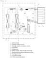
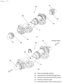
- Fig. 1 is a system block diagram of a heat pump warm water heating device which is a warm water circulation device of a first embodiment of the present invention.
- arrows show flows of a cooling medium and flows of a heating medium such as water and antifreeze liquid.
- the heat pump warm water heating device in this embodiment is composed of a cooling medium circuit 2 and a heating medium circulation circuit 3.
- the cooling medium circuit 2 and the heating medium circulation circuit 3 are placed in one exterior body 1.
- the cooling medium circuit 2 functions as a heat source 2 of the heat pump warm water heating device, and is composed by sequentially and annularly connecting a compressor 5, a water cooling medium heat exchanger 6, a decompression device (expansion valve) 7 and an evaporator 4 to one another through a cooling medium pipe.
- the compressor 5 compresses a cooling medium to high temperature and high pressure.
- the water cooling medium heat exchanger 6 heat-exchanges between a cooling medium and a heating medium such as water and antifreeze liquid.
- the decompression device (expansion valve ) 7 decompresses a cooling medium after it radiates heat in the water cooling medium heat exchanger 6.
- the evaporator 4 heat-exchanges between air and a cooling medium.
- R410A, R32 or carbon dioxide is used as a cooling medium which circulates in the cooling medium circuit.
- the heating medium circulation circuit 3 is composed by sequentially connecting, through a heating medium pipe, a filter-mounting section 20, a circulation pump 9, the water cooling medium heat exchanger 6 and an auxiliary heater 15 to one another from a heating medium backward (in-bound) port 19 to a heating medium forward (out-bound) port 16.
- the heating medium pipe of the heating medium circulation circuit 3 is provided with a pressure relief valve 10, a purge valve 11, a flow sensor 12, an expansion tank 13 and a pressure gauge 14.
- the pressure relief valve 10, the purge valve 11, the flow sensor 12, the expansion tank 13 and the pressure gauge 14 are placed downstream from the filter-mounting section 20.
- the pressure relief valve 10, the flow sensor 12, the expansion tank 13 and the pressure gauge 14 are placed downstream from the water cooling medium heat exchanger 6, and the purge valve 11 is placed in a pipe provided with the auxiliary heater 15.
- a heating medium flows in from the heating medium backward port 19, and flows toward the water cooling medium heat exchanger 6, and the heating medium is heated by a cooling medium which flows through the high temperature and high pressure water cooling medium heat exchanger 6 compressed by the compressor 5.
- the heated high temperature heating medium flows out from the heating medium forward port 16.
- a heating medium backward (in-bound) pipe 18 is connected to the heating medium backward port 19, and a heating medium forward (out-bound) pipe 17 is connected to the heating medium forward port 16.
- the heating medium in-bound pipe 18 connects a heating terminal 8 and the heating medium backward port 19 to each other, and the heating medium out-bound pipe 17 connects the heating terminal 8 and the heating medium forward port 16 to each other.
- the circulation pump 9 By driving the circulation pump 9, the high temperature heating medium is conveyed from the heating medium forward port 16 to the heating terminal 8, and after the heating medium radiates heat in the heating terminal 8, the heating medium again flows from the heating medium backward port 19 into the heating medium circulation circuit 3.
- the heating medium which flows from the heating medium backward port 19 into the heating medium circulation circuit 3 passes through the filter-mounting section 20, the circulation pump 9, the water cooling medium heat exchanger 6 and the auxiliary heater 15, and is conveyed from the heating medium forward port 16 to the heating terminal 8.
- the filter-mounting section 20 is placed in the heating medium circulation circuit 3 downstream from the heating medium backward port 19 and upstream from the circulation pump 9.
- the heating medium which is heated and produced by the water cooling medium heat exchanger 6 is supplied from the heating medium circulation circuit 3 to the heating terminal 8 through the heating medium forward pipe 17, the heating medium heats a room and then, it returns from the heating terminal 8 to the heating medium circulation circuit 3 through the heating medium backward pipe 18.
- the heating terminal 8 may be a panel-like external radiator such as a radiation heater/cooler, or a fan convector having a panel heater or a blower fan.
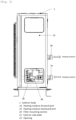
- a back surface of the exterior body 1 is provided with the heating medium forward port 16 and the heating medium backward port 19.
- the heating medium backward port 19 is placed on the back surface of the exterior body 1 at a position lower than the heating medium forward port 16.
- the filter-mounting section 20 is placed at a position in the exterior body 1 opposed to an exterior side plate 21 of the exterior body 1 at the same height as that of the heating medium backward port 19.
- the exterior side plate 21 configures a side surface of the exterior body 1.
- the exterior side plate 21 is provided with an opening 22.
- the opening 22 is placed at a position opposed to the filter-mounting section 20.
- the opening 22 is provided with an opening/closing plate 23 which closes the opening 22.
- the opening/closing plate 23 is fixed to the exterior side plate 21 through a fastening tool (e.g., screw), and closes the opening 22 in normal times. By detaching the opening/closing plate 23 from the exterior side plate 21, maintenance of the filter-mounting section 20 can be performed from the opening 22.
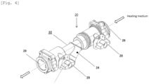
- the filter-mounting section 20 includes a heating medium flow path portion 33 which forms a flow path of a heating medium, and a filter storing section 24 which is inclined with respect to the heating medium flow path portion 33.
- One end opening of the filter storing section 24 is located in the heating medium flow path portion 33, and a sealing plug 26 is detachably mounted on the other end opening of the filter storing section 24.
- the filter-mounting section 20 is placed in the exterior body 1 such that the heating medium flow path portion 33 is directed in a horizontal direction, the other end opening of the filter storing section 24 is located downstream of the heating medium flow path portion 33 from the one end opening of the filter storing section 24, and the other end opening of the filter storing section 24 is located at a position lower than the heating medium flow path portion 33.
- a cylindrical filter 25 is stored in the filter storing section 24.
- the sealing plug 26 is provided with a magnet storing section 34.
- a magnet 35 can be stored in the magnet storing section 34.
- An upper end 34U of the magnet storing section 34 is placed in the filter storing section 24 in a state where the sealing plug 26 is mounted on the filter storing section 24.
- One end (upper end) 25U of the cylindrical filter 25 abuts against the heating medium flow path portion 33 and the other end (lower end) 25D of the cylindrical filter 25 abuts against the sealing plug 26 in a state where the sealing plug 26 is mounted on the filter storing section 24.
- the filter storing section 24 is inclined downward with respect to the heating medium flow path portion 33 and the filter storing section 24 projects downward from the heating medium flow path portion 33 in a state where the filter-mounting section 20 is placed in the exterior body 1. Therefore, the cylindrical filter 25 is also inclined downward with respect to the heating medium flow path portion 33, and is located at a position projecting downward from the heating medium flow path portion 33.
- the upper end 34U of the magnet storing section 34 is located inside the cylindrical filter 25 in a state where the sealing plug 26 is mounted on the filter storing section 24. That is, the upper end 34U of the magnet storing section 34 is located higher than at least the lower end 25D of the filter 25 and lower than an upper end 25U of the filter 25 in the height direction in a state where the filter-mounting section 20 is placed in the exterior body 1. Therefore, the upper end 34U of the magnet storing section 34 is located between the upper end 25U and the lower end 25D of the filter 25 in a state where the sealing plug 26 is mounte4d on the filter storing section 24.
- the magnet storing section 34 covers a periphery of the magnet 35 so that a heating medium flowing through the heating medium flow path portion 33 does not come into direct contact with the magnet 35.
- the magnet storing section 34 is made of non-magnetic body. As a material of the non-magnetic body, it is possible to use resin or non-magnetic body metal such as brass.
- An upper end opening of the cylindrical filter 25 is inclined with respect to the heating medium flow path portion 33. According to this, a heating medium flowing through the heating medium flow path portion 33 enters the filter 25 from the upper end opening of the cylindrical filter 25 and passes through a side surface of the filter 25.
- the filter 25 collects foreign matters which are mixed in the heating medium circulation circuit 3 or the heating terminal 8. Foreign matters of magnetic bodies such as iron powder and copper mixed in the heating medium circulation circuit 3 or the heating terminal 8 adhere to the outer surface of the magnet storing section 34 by an adsorption force of the magnet 35 stored in the magnet storing section 34 located inside the filter 25.
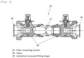
- Fig. 6 is a partial sectional view of a valve section of the filter-mounting section in the first embodiment of the present invention.
- Both sides of the filter-mounting section 20 are provided with valves 28 having opening/closing functions.
- the one end opening of the filter storing section 24 is placed between the pair of valves 28.
- both the valves 28 are closed. After the flow of the heating medium in the filter-mounting section 20 is stopped by closing both the valves 28, maintenance is performed.
- Fig. 7(a) is a diagram of a structure before the filter-mounting section and the heating medium pipes in the first embodiment of the invention are connected to each other
- Fig. 7(b) is a diagram of a structure after the filter-mounting section and the heating medium pipes are connected to each other.
- Cylindrical recessed-fitting shapes 29 which will be connected to heating medium pipes 32 are formed on both ends of the filter-mounting section 20.
- the heating medium pipes 32 are connected to both the ends of the filter-mounting section 20 such that the heating medium flow path portion 33 and the heating medium pipes 32 are coaxially aligned with each other in series. Ends of the heating medium pipes 32 are cylindrical projecting-fitting shapes 30 which fitted to the cylindrical recessed-fitting shapes 29 formed on the filter-mounting section 20.
- These cylindrical recessed and projecting fitting connection structures are configured such that the cylindrical projecting-fitting shapes 30 are inserted into the cylindrical recessed-fitting shapes 29 and they are crimped, fitted and connected to each other through annular fasteners (not shown). Since the heating medium flow path portion 33 is coaxially connected to the heating medium pipes 32, an operator can connect the filter-mounting section 20 and the heating medium pipes 32 to each other by rotating the filter-mounting section 20.
- shapes of the mutual ends may be opposite to each other between these parts.
- Fig. 8 is a part development view of the filter-mounting section in the first embodiment of the invention
- Fig. 9 is a part development view of the sealing plug of the warm water circulation device in the first embodiment of the invention.
- An O-ring 31 is mounted around the sealing plug 26.
- the O-ring 31 prevents a heating medium such as antifreeze liquid from leaking outside when the sealing plug 26 is mounted on the filter storing section 24.
- An upper end of the sealing plug 26 which is closest to the heating medium flow path portion 33 is provided with the magnet storing section 34, and the magnet 35 can be inserted from one end into a cylindrical hole provided in an inner side of the magnet storing section 34.
- a cap 36 can detachably be mounted on the sealing plug 26 from the other end of the magnet 35.
- the cap 36 and the magnet 35 are fixed to each other through an adhesive or the like. That is, an inner surface of the magnet storing section 34 and the cap 36 cover a periphery of the magnet 35.
- the cap 36 is provided with a male screw 37, and the sealing plug 26 is provided with a female screw 38. According to this, the cap 36 can fix the magnet 35 to the magnet storing section 34, and can detachably be mounted on the sealing plug 26.
- the magnet 35 can be taken out from the sealing plug 26. If the magnet 35 is taken out from the sealing plug 26, foreign matters of magnetic bodies such as iron powder and copper which are sucked onto the outer surface of the magnet storing section 34 are removed from the outer surface of the magnet storing section 34. Therefore, it is possible to easily remove the foreign matters.
- the heat pump warm water heating device of this embodiment has the following effects as described above.
- the magnet storing section 34 which covers the periphery of the magnet 35 and stores the magnet is placed inside the filter 25 having the function to collect foreign matters. According to this, it is possible to miniaturize a part which removes foreign matters flowing through the heating medium circulation circuit 3. Further, since the magnet 35 is not in direct contact with a heating medium, a possibility of corrosion or the like is low, and endurance of the magnet 35 can be enhanced.
- the warm water circulation device includes the sealing plug 26 which is detachably mounted on the heating medium circulation circuit 3, and the magnet storing section 34 is provided on the sealing plug 26. According to this, when the sealing plug 26 is detached from the filter storing section 24 of the heating medium circulation circuit 3, the magnet 35 which is stored in the magnet storing section 34 is also detached from the filter storing section 24 of the heating medium circulation circuit 3. Therefore, foreign matters of magnetic bodies which adhere to the outer surface of the magnet storing section 34 can easily be removed, and it is possible to provide a warm water circulation device having excellent maintainability.
- the magnet storing section 34 is made of non-magnetic body material, and the magnet 35 is detachably stored in the magnet storing section 34. Therefore, since the magnet 35 is covered with the non-magnetic body material, foreign matters of the magnetic bodies in the heating medium circulation circuit 3 do not adhere directly to the magnet 35,and the foreign matters adhere to the outer surface of the magnet storing section 34 by the adsorption force of the magnet 35.
- the adsorption force of the magnet 35 with respect to the foreign matters of the magnetic bodies which adhere to the outer surface of the magnet storing section 34 is interrupted or blocked by detaching the sealing plug 26 provided with the magnet storing section 34 from the filter storing section 24 of the heating medium circulation circuit 3 and by detaching the magnet 35 from the magnet storing section 34. Therefore, it is possible to easily remove the foreign matters of magnetic bodies which adhere to the outer surface of the magnet storing section 34, and it is possible to provide a warm water circulation device having excellent maintainability.
- the sealing plug 26 holds the filter 25 detachably, the sealing plug 26 can be mounted on the filter storing section 24 of the heating medium circulation circuit 3 and the filter 25 and the magnet 35 stored in the magnet storing section 34 can be placed in the filter storing section 24 of the heating medium circulation circuit 3 at the same time. Therefore, foreign matters of magnetic bodies flowing through the heating medium circulation circuit 3 can be removed, and it is possible to provide a warm water circulation device having excellent assemblability.
- the warm water circulation device of the invention can be applied not only to domestic warm water circulation devices but also to warm water circulation devices for professional use.
Landscapes
- Engineering & Computer Science (AREA)
- Chemical & Material Sciences (AREA)
- Chemical Kinetics & Catalysis (AREA)
- Water Supply & Treatment (AREA)
- Physics & Mathematics (AREA)
- Thermal Sciences (AREA)
- Combustion & Propulsion (AREA)
- Mechanical Engineering (AREA)
- General Engineering & Computer Science (AREA)
- Steam Or Hot-Water Central Heating Systems (AREA)
- Filtration Of Liquid (AREA)
Description
- The present invention relates to a warm water circulation device.
- In a device of this kind through which warm water flows, there exists a conventional structure having the following means for collecting foreign matters which flow together with warm water.
- A main body has a sidewall having an inlet and an outlet for water supply. A plate-shaped mesh-like filter which is warped in an arc form is inserted into the main body from its opening bottom.
- A sheet material is installed on an inner bottom surface of a bottom lid in which a magnet is embedded, and the bottom lid is mounted on a position where the outlet is covered along an inner peripheral surface of the sidewall of the main body such that the bottom lid can be inserted and removed.
- According to this, iron in the supplied water which flows in from the inlet is adsorbed by a magnetic force of the magnet, the iron is precipitated onto the sheet material, and impurities in the supplied water is removed by a filter.
- The precipitated iron are cleaned by turning the bottom lid and detaching the bottom lid from the main body, and further detaching the sheet material from the bottom lid. The impurities which are removed by the filter are cleaned by pulling out the filter from the opening bottom of the main body (see patent document 1).
- In
patent document 2, a filter for treating a fluid in the piping of heating and/or cooling systems is disclosed. The filter comprises a cylindrical body having an internal chamber, with a magnetic filtering element and a mesh type-filtering element housed in said chamber. A plug covers a portion of the cylindrical body and allows removal of the filtering elements. - Furthermore, strainer devices of substantially Y-shape are known from
patent documents -
- [Patent Document 1]
Japanese Patent Application Laid-open No.2001-232114 - [Patent Document 2]
EP patent application 3 159 313 A1 - [Patent Document 3]
Japanese Patent Application Laid-open No.2010-279886 - [Patent Document 4]
Japanese Patent Application Laid-open No.2015-167883 - In the above-described conventional structure, however, since the magnet is disposed below the mesh-like filter, there is a problem that a size of a part for collecting the foreign matters which flows together with the warm water becomes large.
- The present invention is for solving the conventional problem, and it is an object of the invention to provide a warm water circulation device capable of miniaturizing a part for collecting foreign matters which flow together with warm water.
- To solve the conventional problem, the present invention provides a warm water circulation device including: a heat source; a heating medium circulation circuit through which a heating medium heated by the heat source circulates; a filter-mounting section including a heating medium flow path portion which forms a flow path of the heating medium, and a filter storing section which is inclined with respect to the heating medium flow path portion and which stores a cylindrical filter having a function to collect a foreign matter, wherein one end opening of the filter storing section is located in the heating medium flow path portion; and a sealing plug mounted detachably on the other end opening of the filter storing section and being provided with a magnet storing section for covering a periphery of a magnet and storing the magnet; an upper end of at least the magnet storing section is located higher than a lower end of the filter in a height direction of the warm water circulation device; the heat source and the heating medium circulation circuit are placed in one exterior body having an opening, the opening is placed at a position opposed to the filter-mounting section; the filter-mounting section is placed in the heating medium circulation circuit downstream from a heating medium backward port and upstream from a circulation pump; the filter-mounting section is placed at a position in the exterior body opposed to an exterior side plate of the exterior body at the same height as that of the heating medium backward port; the opening is provided with an opening/closing plate which closes the opening, and the opening/closing plate is fixed to the exterior side plate through a fastening tool (e.g. screw), and closes the opening in normal times; and the filter-mounting section is placed in the exterior body such that the heating medium flow path portion is directed in a horizontal direction, the other end opening of the filter storing section is located downstream of the heating medium flow path portion from the one end opening of the filter storing section, and the other end opening of the filter storing section is located at a position lower than the heating medium flow path portion.
- According to this, in the height direction, an upper end of the magnet storing section which covers at least the periphery of the magnet and in which the magnet is stored is located higher than the lower end of the filter which has a function to collect foreign matters. Therefore, it is possible to miniaturize a part for removing foreign matters which are generated and flow through the heating medium circulation circuit when heating medium circulation circuit and a heating terminal are connected to each other at the time of installation of the warm water circulation device and when a pipe which connects the heating medium circulation circuit and the heating terminal to each other is dilapidated.
- Further, since the magnet is not in direct contact with the heating medium, a possibility of corrosion and the like is low, and endurance of the magnet can be enhanced.
- According to the present invention, it is possible to provide a warm water circulation device capable of miniaturizing a part for collecting foreign matters which flow together with warm water.
-
-
Fig. 1 is a system block diagram of a warm water circulation device of a first embodiment of the present invention; -
Fig. 2 is a perspective view of an outward appearance of the warm water circulation device; -
Fig. 3 is a side view of the warm water circulation device; -
Fig. 4 is a perspective view of an outward appearance of a filter-mounting section of the warm water circulation device; -
Fig. 5 is a partial sectional view of the filter-mounting section; -
Fig. 6 is a partial sectional view of a valve section of the filter-mounting section of the warm water circulation device; - Fig. 7(a) is a diagram of a structure before the filter-mounting section and a heating medium pipes of the warm water circulation device in the first embodiment of the invention are connected to each other, and Fig. 7(b) is a diagram of a structure after the filter-mounting section and the heating medium pipes are connected to each other;
-
Fig. 8 is a part development view of the filter-mounting section of the warm water circulation device in the first embodiment of the invention; and -
Fig. 9 is a part development view of a sealing plug of the warm water circulation device. - A first aspect of the present invention provides a warm water circulation device including: a heat source; a heating medium circulation circuit through which a heating medium heated by the heat source circulates; a filter-mounting section including a heating medium flow path portion which forms a flow path of the heating medium, and a filter storing section which is inclined with respect to the heating medium flow path portion and which stores a cylindrical filter having a function to collect a foreign matter, wherein one end opening of the filter storing section is located in the heating medium flow path portion; and a sealing plug mounted detachably on the other end opening of the filter storing section and being provided with a magnet storing section for covering a periphery of a magnet and storing the magnet; an upper end of at least the magnet storing section is located higher than a lower end of the filter in a height direction of the warm water circulation device; the heat source and the heating medium circulation circuit are placed in one exterior body having an opening, the opening is placed at a position opposed to the filter-mounting section; the filter-mounting section is placed in the heating medium circulation circuit downstream from a heating medium backward port and upstream from a circulation pump; the filter-mounting section is placed at a position in the exterior body opposed to an exterior side plate of the exterior body at the same height as that of the heating medium backward port; the opening is provided with an opening/closing plate which closes the opening, and the opening/closing plate is fixed to the exterior side plate through a fastening tool (e.g. screw), and closes the opening in normal times; and the filter-mounting section is placed in the exterior body such that the heating medium flow path portion is directed in a horizontal direction, the other end opening of the filter storing section is located downstream of the heating medium flow path portion from the one end opening of the filter storing section, and the other end opening of the filter storing section is located at a position lower than the heating medium flow path portion.
- According to this, in the height direction, an upper end of the magnet storing section which covers at least the periphery of the magnet and in which the magnet is stored is located higher than the lower end of the filter which has a function to collect foreign matters. Therefore, it is possible to miniaturize a part for removing foreign matters which are generated and flow through the heating medium circulation circuit when heating medium circulation circuit and a heating terminal are connected to each other at the time of installation of the warm water circulation device and when a pipe which connects the heating medium circulation circuit and the heating terminal to each other is dilapidated.
- Further, since the magnet is not in direct contact with the heating medium, a possibility of corrosion and the like is low, and endurance of the magnet can be enhanced.
- Accordingly, when the sealing plug is detached from the heating medium circulation circuit, the magnet stored in the magnet storing section is also detached from the heating medium circulation circuit at the same time.
- Therefore, it is possible to easily remove foreign matters of magnetic bodies which adhere to an outer surface of the magnet storing section by detaching the sealing plug from the heating medium circulation circuit, and it is possible to provide a warm water circulation device having excellent maintainability.
- According to a second aspect of the invention, in the first aspect, the magnet storing section is made of non-magnetic body material, and the magnet is detachably stored in the magnet storing section.
- According to this, since the heating medium and the foreign matters of the magnetic bodies in the heating medium circulation circuit do not directly adhere to the magnet, a possibility of corrosion and the like is low, and endurance of the magnet can be enhanced.
- Further, since the magnet is covered with the non-magnetic body, foreign matters of the magnetic bodies in the heating medium circulation circuit do not directly adhere to the magnet, and the foreign matters adhere to the outer surface of the magnet storing section by an adsorption force of the magnet.
- Therefore, since the adsorption force of the magnet with respect to the foreign matters of the magnetic bodies which adhere to the outer surface of the magnet storing section is interrupted or blocked by removing the magnet storing section from the heating medium circulation circuit and detaching the magnet from the magnet storing section, it is possible to easily remove the foreign matters of the magnetic bodies which adhere to the outer surface of the magnet storing section, and it is possible to provide a warm water circulation device having excellent maintainability.
- According to a third aspect of the invention, in the first aspect, the sealing plug detachably holds the filter.
- According to this, when the sealing plug is mounted on the heating medium circulation circuit, the filter and the magnet stored in the magnet storing section can be placed on the heating medium circulation circuit at the same time.
- Therefore, it is possible to remove the foreign matters of the magnetic bodies flowing through the heating medium circulation circuit, and to provide a warm water circulation device having excellent assemblability.
- According to this, when the sealing plug is mounted on the heating medium circulation circuit, the filter and the magnet stored in the magnet storing section can be placed on the heating medium circulation circuit at the same time.
- According to a fourth aspect of the invention, in the second aspect, the non-magnetic body material is resin or non-magnetic body metal.
- According to this, since the heating medium and the foreign matters of the magnetic bodies in the heating medium circulation circuit do not directly adhere to the magnet, a possibility of corrosion and the like is low, and endurance of the magnet can be enhanced.
- According to a fifth aspect of the invention, in the first aspect, the heat source is a cooling medium circuit, and the heating medium is water or antifreeze liquid.
- According to this, it is possible to provide a heat pump warm water heating device having excellent endurance with respect to foreign matters of the magnetic bodies flowing through the heating medium circulation circuit and excellent operation efficiency.
- An embodiment of the present invention will be described below with reference to the drawings. The invention is not limited to the embodiment.
-
Fig. 1 is a system block diagram of a heat pump warm water heating device which is a warm water circulation device of a first embodiment of the present invention. InFig. 1 , arrows show flows of a cooling medium and flows of a heating medium such as water and antifreeze liquid. - As shown in
Fig. 1 , the heat pump warm water heating device in this embodiment is composed of a coolingmedium circuit 2 and a heatingmedium circulation circuit 3. The coolingmedium circuit 2 and the heatingmedium circulation circuit 3 are placed in oneexterior body 1. - The cooling
medium circuit 2 functions as aheat source 2 of the heat pump warm water heating device, and is composed by sequentially and annularly connecting a compressor 5, a water coolingmedium heat exchanger 6, a decompression device (expansion valve) 7 and anevaporator 4 to one another through a cooling medium pipe. The compressor 5 compresses a cooling medium to high temperature and high pressure. The water coolingmedium heat exchanger 6 heat-exchanges between a cooling medium and a heating medium such as water and antifreeze liquid. The decompression device (expansion valve ) 7 decompresses a cooling medium after it radiates heat in the water coolingmedium heat exchanger 6. Theevaporator 4 heat-exchanges between air and a cooling medium. As a cooling medium which circulates in the cooling medium circuit, R410A, R32 or carbon dioxide is used. - The heating
medium circulation circuit 3 is composed by sequentially connecting, through a heating medium pipe, a filter-mountingsection 20, acirculation pump 9, the water coolingmedium heat exchanger 6 and anauxiliary heater 15 to one another from a heating medium backward (in-bound)port 19 to a heating medium forward (out-bound)port 16. The heating medium pipe of the heatingmedium circulation circuit 3 is provided with apressure relief valve 10, apurge valve 11, aflow sensor 12, anexpansion tank 13 and apressure gauge 14. Thepressure relief valve 10, thepurge valve 11, theflow sensor 12, theexpansion tank 13 and thepressure gauge 14 are placed downstream from the filter-mountingsection 20. In this embodiment, thepressure relief valve 10, theflow sensor 12, theexpansion tank 13 and thepressure gauge 14 are placed downstream from the water coolingmedium heat exchanger 6, and thepurge valve 11 is placed in a pipe provided with theauxiliary heater 15. - By driving the
circulation pump 9, a heating medium flows in from the heating mediumbackward port 19, and flows toward the water coolingmedium heat exchanger 6, and the heating medium is heated by a cooling medium which flows through the high temperature and high pressure water coolingmedium heat exchanger 6 compressed by the compressor 5. The heated high temperature heating medium flows out from the heating mediumforward port 16. - A heating medium backward (in-bound)
pipe 18 is connected to the heating mediumbackward port 19, and a heating medium forward (out-bound)pipe 17 is connected to the heating mediumforward port 16. The heating medium in-boundpipe 18 connects aheating terminal 8 and the heating mediumbackward port 19 to each other, and the heating medium out-boundpipe 17 connects theheating terminal 8 and the heating mediumforward port 16 to each other. - By driving the
circulation pump 9, the high temperature heating medium is conveyed from the heating mediumforward port 16 to theheating terminal 8, and after the heating medium radiates heat in theheating terminal 8, the heating medium again flows from the heating mediumbackward port 19 into the heatingmedium circulation circuit 3. The heating medium which flows from the heating mediumbackward port 19 into the heatingmedium circulation circuit 3 passes through the filter-mountingsection 20, thecirculation pump 9, the water coolingmedium heat exchanger 6 and theauxiliary heater 15, and is conveyed from the heating mediumforward port 16 to theheating terminal 8. - The filter-mounting
section 20 is placed in the heatingmedium circulation circuit 3 downstream from the heating mediumbackward port 19 and upstream from thecirculation pump 9. - The heating medium which is heated and produced by the water cooling
medium heat exchanger 6 is supplied from the heatingmedium circulation circuit 3 to theheating terminal 8 through the heatingmedium forward pipe 17, the heating medium heats a room and then, it returns from theheating terminal 8 to the heatingmedium circulation circuit 3 through the heating mediumbackward pipe 18. - The
heating terminal 8 may be a panel-like external radiator such as a radiation heater/cooler, or a fan convector having a panel heater or a blower fan. - Next, a structure of the heat pump warm water heating device in this embodiment will be described using
Figs. 2 and3 . - As shown in
Figs. 2 and3 , a back surface of theexterior body 1 is provided with the heating mediumforward port 16 and the heating mediumbackward port 19. The heating mediumbackward port 19 is placed on the back surface of theexterior body 1 at a position lower than the heating mediumforward port 16. - The filter-mounting
section 20 is placed at a position in theexterior body 1 opposed to anexterior side plate 21 of theexterior body 1 at the same height as that of the heating mediumbackward port 19. Theexterior side plate 21 configures a side surface of theexterior body 1. - The
exterior side plate 21 is provided with anopening 22. Theopening 22 is placed at a position opposed to the filter-mountingsection 20. Theopening 22 is provided with an opening/closing plate 23 which closes theopening 22. The opening/closing plate 23 is fixed to theexterior side plate 21 through a fastening tool (e.g., screw), and closes theopening 22 in normal times. By detaching the opening/closing plate 23 from theexterior side plate 21, maintenance of the filter-mountingsection 20 can be performed from theopening 22. - As shown in
Figs. 4 and5 , the filter-mountingsection 20 includes a heating mediumflow path portion 33 which forms a flow path of a heating medium, and afilter storing section 24 which is inclined with respect to the heating mediumflow path portion 33. - One end opening of the
filter storing section 24 is located in the heating mediumflow path portion 33, and a sealingplug 26 is detachably mounted on the other end opening of thefilter storing section 24. - The filter-mounting
section 20 is placed in theexterior body 1 such that the heating mediumflow path portion 33 is directed in a horizontal direction, the other end opening of thefilter storing section 24 is located downstream of the heating mediumflow path portion 33 from the one end opening of thefilter storing section 24, and the other end opening of thefilter storing section 24 is located at a position lower than the heating mediumflow path portion 33. - A
cylindrical filter 25 is stored in thefilter storing section 24. - The sealing
plug 26 is provided with amagnet storing section 34. Amagnet 35 can be stored in themagnet storing section 34. Anupper end 34U of themagnet storing section 34 is placed in thefilter storing section 24 in a state where the sealingplug 26 is mounted on thefilter storing section 24. - One end (upper end) 25U of the
cylindrical filter 25 abuts against the heating mediumflow path portion 33 and the other end (lower end) 25D of thecylindrical filter 25 abuts against the sealingplug 26 in a state where the sealingplug 26 is mounted on thefilter storing section 24. - The
filter storing section 24 is inclined downward with respect to the heating mediumflow path portion 33 and thefilter storing section 24 projects downward from the heating mediumflow path portion 33 in a state where the filter-mountingsection 20 is placed in theexterior body 1. Therefore, thecylindrical filter 25 is also inclined downward with respect to the heating mediumflow path portion 33, and is located at a position projecting downward from the heating mediumflow path portion 33. - The
upper end 34U of themagnet storing section 34 is located inside thecylindrical filter 25 in a state where the sealingplug 26 is mounted on thefilter storing section 24. That is, theupper end 34U of themagnet storing section 34 is located higher than at least thelower end 25D of thefilter 25 and lower than anupper end 25U of thefilter 25 in the height direction in a state where the filter-mountingsection 20 is placed in theexterior body 1. Therefore, theupper end 34U of themagnet storing section 34 is located between theupper end 25U and thelower end 25D of thefilter 25 in a state where the sealingplug 26 is mounte4d on thefilter storing section 24. - The
magnet storing section 34 covers a periphery of themagnet 35 so that a heating medium flowing through the heating mediumflow path portion 33 does not come into direct contact with themagnet 35. Themagnet storing section 34 is made of non-magnetic body. As a material of the non-magnetic body, it is possible to use resin or non-magnetic body metal such as brass. - An upper end opening of the
cylindrical filter 25 is inclined with respect to the heating mediumflow path portion 33. According to this, a heating medium flowing through the heating mediumflow path portion 33 enters thefilter 25 from the upper end opening of thecylindrical filter 25 and passes through a side surface of thefilter 25. - The
filter 25 collects foreign matters which are mixed in the heatingmedium circulation circuit 3 or theheating terminal 8. Foreign matters of magnetic bodies such as iron powder and copper mixed in the heatingmedium circulation circuit 3 or theheating terminal 8 adhere to the outer surface of themagnet storing section 34 by an adsorption force of themagnet 35 stored in themagnet storing section 34 located inside thefilter 25. -
Fig. 6 is a partial sectional view of a valve section of the filter-mounting section in the first embodiment of the present invention. Both sides of the filter-mountingsection 20 are provided withvalves 28 having opening/closing functions. The one end opening of thefilter storing section 24 is placed between the pair ofvalves 28. When thefilter 25 is attached to and detached from thefilter storing section 24, both thevalves 28 are closed. After the flow of the heating medium in the filter-mountingsection 20 is stopped by closing both thevalves 28, maintenance is performed. - Fig. 7(a) is a diagram of a structure before the filter-mounting section and the heating medium pipes in the first embodiment of the invention are connected to each other, and Fig. 7(b) is a diagram of a structure after the filter-mounting section and the heating medium pipes are connected to each other. Cylindrical recessed-
fitting shapes 29 which will be connected to heatingmedium pipes 32 are formed on both ends of the filter-mountingsection 20. - The
heating medium pipes 32 are connected to both the ends of the filter-mountingsection 20 such that the heating mediumflow path portion 33 and theheating medium pipes 32 are coaxially aligned with each other in series. Ends of theheating medium pipes 32 are cylindrical projecting-fitting shapes 30 which fitted to the cylindrical recessed-fitting shapes 29 formed on the filter-mountingsection 20. - These cylindrical recessed and projecting fitting connection structures are configured such that the cylindrical projecting-
fitting shapes 30 are inserted into the cylindrical recessed-fitting shapes 29 and they are crimped, fitted and connected to each other through annular fasteners (not shown). Since the heating mediumflow path portion 33 is coaxially connected to theheating medium pipes 32, an operator can connect the filter-mountingsection 20 and theheating medium pipes 32 to each other by rotating the filter-mountingsection 20. In the cylindrical recessed and projecting fitting connection structures, shapes of the mutual ends may be opposite to each other between these parts. -
Fig. 8 is a part development view of the filter-mounting section in the first embodiment of the invention, andFig. 9 is a part development view of the sealing plug of the warm water circulation device in the first embodiment of the invention. - If an
annular fastener 27 which fixes thefilter storing section 24 and the sealingplug 26 to each other is detached and then the sealingplug 26 mounted on the lower end opening of thefilter storing section 24 is detached from thefilter storing section 24, thefilter 25 can be detached from thefilter storing section 24. - An O-
ring 31 is mounted around the sealingplug 26. The O-ring 31 prevents a heating medium such as antifreeze liquid from leaking outside when the sealingplug 26 is mounted on thefilter storing section 24. - An upper end of the sealing
plug 26 which is closest to the heating mediumflow path portion 33 is provided with themagnet storing section 34, and themagnet 35 can be inserted from one end into a cylindrical hole provided in an inner side of themagnet storing section 34. - A
cap 36 can detachably be mounted on the sealingplug 26 from the other end of themagnet 35. Thecap 36 and themagnet 35 are fixed to each other through an adhesive or the like. That is, an inner surface of themagnet storing section 34 and thecap 36 cover a periphery of themagnet 35. - The
cap 36 is provided with amale screw 37, and the sealingplug 26 is provided with afemale screw 38. According to this, thecap 36 can fix themagnet 35 to themagnet storing section 34, and can detachably be mounted on the sealingplug 26. - According to this, after the sealing
plug 26 is detached from thefilter storing section 24, if thecap 36 is detached from the sealingplug 26, themagnet 35 can be taken out from the sealingplug 26. If themagnet 35 is taken out from the sealingplug 26, foreign matters of magnetic bodies such as iron powder and copper which are sucked onto the outer surface of themagnet storing section 34 are removed from the outer surface of themagnet storing section 34. Therefore, it is possible to easily remove the foreign matters. - The heat pump warm water heating device of this embodiment has the following effects as described above.
- The
magnet storing section 34 which covers the periphery of themagnet 35 and stores the magnet is placed inside thefilter 25 having the function to collect foreign matters. According to this, it is possible to miniaturize a part which removes foreign matters flowing through the heatingmedium circulation circuit 3. Further, since themagnet 35 is not in direct contact with a heating medium, a possibility of corrosion or the like is low, and endurance of themagnet 35 can be enhanced. - The warm water circulation device includes the sealing
plug 26 which is detachably mounted on the heatingmedium circulation circuit 3, and themagnet storing section 34 is provided on the sealingplug 26. According to this, when the sealingplug 26 is detached from thefilter storing section 24 of the heatingmedium circulation circuit 3, themagnet 35 which is stored in themagnet storing section 34 is also detached from thefilter storing section 24 of the heatingmedium circulation circuit 3. Therefore, foreign matters of magnetic bodies which adhere to the outer surface of themagnet storing section 34 can easily be removed, and it is possible to provide a warm water circulation device having excellent maintainability. - Further, the
magnet storing section 34 is made of non-magnetic body material, and themagnet 35 is detachably stored in themagnet storing section 34. Therefore, since themagnet 35 is covered with the non-magnetic body material, foreign matters of the magnetic bodies in the heatingmedium circulation circuit 3 do not adhere directly to themagnet 35,and the foreign matters adhere to the outer surface of themagnet storing section 34 by the adsorption force of themagnet 35. - According to this, the adsorption force of the
magnet 35 with respect to the foreign matters of the magnetic bodies which adhere to the outer surface of themagnet storing section 34 is interrupted or blocked by detaching the sealingplug 26 provided with themagnet storing section 34 from thefilter storing section 24 of the heatingmedium circulation circuit 3 and by detaching themagnet 35 from themagnet storing section 34. Therefore, it is possible to easily remove the foreign matters of magnetic bodies which adhere to the outer surface of themagnet storing section 34, and it is possible to provide a warm water circulation device having excellent maintainability. - Further, since the sealing
plug 26 holds thefilter 25 detachably, the sealingplug 26 can be mounted on thefilter storing section 24 of the heatingmedium circulation circuit 3 and thefilter 25 and themagnet 35 stored in themagnet storing section 34 can be placed in thefilter storing section 24 of the heatingmedium circulation circuit 3 at the same time. Therefore, foreign matters of magnetic bodies flowing through the heatingmedium circulation circuit 3 can be removed, and it is possible to provide a warm water circulation device having excellent assemblability. - As described above, according to the present invention, since it is possible to miniaturize a part which collect foreign matters flowing together with warm water, the warm water circulation device of the invention can be applied not only to domestic warm water circulation devices but also to warm water circulation devices for professional use.
-
- 1
- exterior body
- 2
- cooling medium circuit (heat source)
- 3
- heating medium circulation circuit
- 4
- evaporator
- 5
- compressor
- 6
- water cooling medium heat exchanger
- 7
- decompression device (expansion valve)
- 8
- heating terminal
- 9
- circulation pump
- 10
- pressure relief valve
- 11
- purge valve
- 12
- flow sensor
- 13
- expansion tank
- 14
- pressure gauge
- 15
- auxiliary heater
- 16
- heating medium forward port
- 17
- heating medium forward pipe
- 18
- heating medium backward pipe
- 19
- heating medium backward port
- 20
- filter-mounting section
- 21
- exterior side plate
- 22
- opening
- 23
- opening/closing plate
- 24
- filter storing section
- 25
- filter
- 26
- sealing plug
- 27
- fastener
- 28
- valve
- 29
- cylindrical recessed-fitting shape
- 30
- cylindrical projecting-fitting shape
- 31
- O-ring
- 32
- heating medium pipe
- 33
- heating medium flow path portion
- 34
- magnet storing section
- 35
- magnet
- 36
- cap
- 37
- male screw
- 38
- female screw
Claims (5)
- A warm water circulation device comprising:a heat source (2);a heating medium circulation circuit (3) through which a heating medium heated by the heat source (2) circulates;a filter-mounting section (20) including a heating medium flow path portion (33) which forms a flow path of the heating medium, and a filter storing section (24) which is inclined with respect to the heating medium flow path portion (33) and which stores a cylindrical filter (25) having a function to collect a foreign matter, wherein:one end opening of the filter storing section (24) is located in the heating medium flow path portion (33); and a sealing plug (26) mounted detachably on the other end opening of the filter storing section (24) and being provided with a magnet storing section (34) for covering a periphery of a magnet (35) and storing the magnet (35);an upper end (34U) of at least the magnet storing section (34) is located higher than a lower end (25D) of the filter (25) in a height direction of the warm water circulation device;the heat source (2) and the heating medium circulation circuit (3) are placed in one exterior body (1) having an opening (22);the opening (22) is placed at a position opposed to the filter-mounting section (20);the filter-mounting section (20) is placed in the heating medium circulation circuit (3) downstream from a heating medium backward port (19) and upstream from a circulation pump (9);the filter-mounting section (20) is placed at a position in the exterior body (1) opposed to an exterior side plate (21) of the exterior body (1) at the same height as that of the heating medium backward port (19);the opening (22) is provided with an opening/closing plate (23) which closes the opening (22), and the opening/closing plate (23) is fixed to the exterior side plate (21) through a fastening tool (e.g. screw), and closes the opening (22) in normal times; and
the filter-mounting section (20) is placed in the exterior body (1) such that the heating medium flow path portion (33) is directed in a horizontal direction, the other end opening of the filter storing section (24) is located downstream of the heating medium flow path portion (33) from the one end opening of the filter storing section (24), and the other end opening of the filter storing section (24) is located at a position lower than the heating medium flow path portion (33). - The warm water circulation device according to claim 1, wherein
the magnet storing section (34) is made of non-magnetic body material, and the magnet (35) is detachably stored in the magnet storing section (34). - The warm water circulation device according to claim 1, wherein
the sealing plug (26) detachably holds the filter (25). - The warm water circulation device according to claim 2, wherein
the non-magnetic body material is resin or non-magnetic body metal. - The warm water circulation device according to claim 1, wherein
the heat source (2) is a cooling medium circuit (2), and the heating medium is water or antifreeze liquid.
Applications Claiming Priority (1)
| Application Number | Priority Date | Filing Date | Title |
|---|---|---|---|
| JP2018177666A JP2020046167A (en) | 2018-09-21 | 2018-09-21 | Hot water circulation device |
Publications (2)
| Publication Number | Publication Date |
|---|---|
| EP3627059A1 EP3627059A1 (en) | 2020-03-25 |
| EP3627059B1 true EP3627059B1 (en) | 2023-06-21 |
Family
ID=67658510
Family Applications (1)
| Application Number | Title | Priority Date | Filing Date |
|---|---|---|---|
| EP19190419.2A Active EP3627059B1 (en) | 2018-09-21 | 2019-08-07 | Warm water circulation device with magnetic filter |
Country Status (3)
| Country | Link |
|---|---|
| EP (1) | EP3627059B1 (en) |
| JP (1) | JP2020046167A (en) |
| PL (1) | PL3627059T3 (en) |
Family Cites Families (5)
| Publication number | Priority date | Publication date | Assignee | Title |
|---|---|---|---|---|
| JP2001232114A (en) | 2000-02-21 | 2001-08-28 | Atago Seisakusho:Kk | Magnet filter |
| JP2010279886A (en) * | 2009-06-03 | 2010-12-16 | Keihin Hi-Flo Sales Co Ltd | Strainer |
| JP2015167883A (en) * | 2014-03-05 | 2015-09-28 | 株式会社富士通ゼネラル | Strainer device and hot water heating system |
| ITUB201586596U1 (en) * | 2015-10-21 | 2017-04-21 | FILTER FOR THE TREATMENT OF A FLUID IN A PIPE, IN PARTICULAR OF A WATER NETWORK | |
| GB2562772B (en) * | 2017-05-25 | 2019-10-30 | Vexo International Uk Ltd | Fluid treatment |
-
2018
- 2018-09-21 JP JP2018177666A patent/JP2020046167A/en active Pending
-
2019
- 2019-08-07 PL PL19190419.2T patent/PL3627059T3/en unknown
- 2019-08-07 EP EP19190419.2A patent/EP3627059B1/en active Active
Also Published As
| Publication number | Publication date |
|---|---|
| EP3627059A1 (en) | 2020-03-25 |
| JP2020046167A (en) | 2020-03-26 |
| PL3627059T3 (en) | 2023-11-06 |
Similar Documents
| Publication | Publication Date | Title |
|---|---|---|
| JP2019027744A (en) | Heat pump hot water heating machine | |
| EP3627059B1 (en) | Warm water circulation device with magnetic filter | |
| US20120061052A1 (en) | Hydronic system | |
| JP4421525B2 (en) | Water heater | |
| JP5119797B2 (en) | Backflow prevention device, hot water supply device and hot water supply system having the same | |
| KR20170121362A (en) | Boiler for heating and cooling water mat | |
| US11624512B2 (en) | Tankless water heater having integrated scale control module | |
| JPWO2018207759A1 (en) | Vehicle air conditioner and frame applied thereto | |
| JP3898583B2 (en) | Heat exchanger header connection structure | |
| EP3969185B1 (en) | Filter for treating a fluid in a piping of a heating and/or cooling system, in particular of domestic and/or industrial type | |
| JP4285433B2 (en) | Hot water storage tank for water heater | |
| US7462215B2 (en) | Very thin profile filter with large filter media area | |
| JP2013166123A (en) | Strainer and fluid circulation circuit provided with the strainer | |
| JP2007232275A (en) | Outdoor unit for air conditioner | |
| JP2010101502A (en) | Filter mounting structure of gas passage | |
| EP1028298A1 (en) | Heating apparatus having a cast, integrated heat exchanger | |
| CN214746052U (en) | Radiator with filtration | |
| CN217410007U (en) | Filter equipment and water heater | |
| KR200173147Y1 (en) | A water purifier | |
| CN219390044U (en) | Housing assembly for an air treatment device and air treatment device | |
| WO2022137536A1 (en) | Heat-pump water heater, heat pump device equipped with heat-pump water heater, and method for assembling heat-pump water heater | |
| US20070256649A1 (en) | Coolant inspection and filtering system patent | |
| JP5067080B2 (en) | Backflow prevention valve, backflow prevention device having the same, hot water supply device and hot water supply system | |
| KR200404905Y1 (en) | Pipe structure of fan coil unit | |
| CN101878397B (en) | Outdoor unit for refrigeration device |
Legal Events
| Date | Code | Title | Description |
|---|---|---|---|
| PUAI | Public reference made under article 153(3) epc to a published international application that has entered the european phase |
Free format text: ORIGINAL CODE: 0009012 |
|
| STAA | Information on the status of an ep patent application or granted ep patent |
Free format text: STATUS: THE APPLICATION HAS BEEN PUBLISHED |
|
| AK | Designated contracting states |
Kind code of ref document: A1 Designated state(s): AL AT BE BG CH CY CZ DE DK EE ES FI FR GB GR HR HU IE IS IT LI LT LU LV MC MK MT NL NO PL PT RO RS SE SI SK SM TR |
|
| AX | Request for extension of the european patent |
Extension state: BA ME |
|
| STAA | Information on the status of an ep patent application or granted ep patent |
Free format text: STATUS: REQUEST FOR EXAMINATION WAS MADE |
|
| 17P | Request for examination filed |
Effective date: 20200925 |
|
| RBV | Designated contracting states (corrected) |
Designated state(s): AL AT BE BG CH CY CZ DE DK EE ES FI FR GB GR HR HU IE IS IT LI LT LU LV MC MK MT NL NO PL PT RO RS SE SI SK SM TR |
|
| STAA | Information on the status of an ep patent application or granted ep patent |
Free format text: STATUS: EXAMINATION IS IN PROGRESS |
|
| 17Q | First examination report despatched |
Effective date: 20220502 |
|
| GRAP | Despatch of communication of intention to grant a patent |
Free format text: ORIGINAL CODE: EPIDOSNIGR1 |
|
| STAA | Information on the status of an ep patent application or granted ep patent |
Free format text: STATUS: GRANT OF PATENT IS INTENDED |
|
| RIC1 | Information provided on ipc code assigned before grant |
Ipc: B03C 1/30 20060101ALI20221213BHEP Ipc: B03C 1/28 20060101ALI20221213BHEP Ipc: B01D 35/06 20060101ALI20221213BHEP Ipc: B01D 29/31 20060101ALI20221213BHEP Ipc: B03C 1/033 20060101ALI20221213BHEP Ipc: B01D 29/11 20060101ALI20221213BHEP Ipc: F24D 19/00 20060101AFI20221213BHEP |
|
| INTG | Intention to grant announced |
Effective date: 20230113 |
|
| GRAS | Grant fee paid |
Free format text: ORIGINAL CODE: EPIDOSNIGR3 |
|
| GRAA | (expected) grant |
Free format text: ORIGINAL CODE: 0009210 |
|
| STAA | Information on the status of an ep patent application or granted ep patent |
Free format text: STATUS: THE PATENT HAS BEEN GRANTED |
|
| AK | Designated contracting states |
Kind code of ref document: B1 Designated state(s): AL AT BE BG CH CY CZ DE DK EE ES FI FR GB GR HR HU IE IS IT LI LT LU LV MC MK MT NL NO PL PT RO RS SE SI SK SM TR |
|
| REG | Reference to a national code |
Ref country code: CH Ref legal event code: EP |
|
| REG | Reference to a national code |
Ref country code: DE Ref legal event code: R096 Ref document number: 602019031266 Country of ref document: DE |
|
| REG | Reference to a national code |
Ref country code: AT Ref legal event code: REF Ref document number: 1581128 Country of ref document: AT Kind code of ref document: T Effective date: 20230715 |
|
| REG | Reference to a national code |
Ref country code: IE Ref legal event code: FG4D |
|
| REG | Reference to a national code |
Ref country code: LT Ref legal event code: MG9D |
|
| REG | Reference to a national code |
Ref country code: NL Ref legal event code: MP Effective date: 20230621 |
|
| PG25 | Lapsed in a contracting state [announced via postgrant information from national office to epo] |
Ref country code: SE Free format text: LAPSE BECAUSE OF FAILURE TO SUBMIT A TRANSLATION OF THE DESCRIPTION OR TO PAY THE FEE WITHIN THE PRESCRIBED TIME-LIMIT Effective date: 20230621 Ref country code: NO Free format text: LAPSE BECAUSE OF FAILURE TO SUBMIT A TRANSLATION OF THE DESCRIPTION OR TO PAY THE FEE WITHIN THE PRESCRIBED TIME-LIMIT Effective date: 20230921 |
|
| PGFP | Annual fee paid to national office [announced via postgrant information from national office to epo] |
Ref country code: GB Payment date: 20230822 Year of fee payment: 5 Ref country code: CZ Payment date: 20230815 Year of fee payment: 5 |
|
| REG | Reference to a national code |
Ref country code: AT Ref legal event code: MK05 Ref document number: 1581128 Country of ref document: AT Kind code of ref document: T Effective date: 20230621 |
|
| PG25 | Lapsed in a contracting state [announced via postgrant information from national office to epo] |
Ref country code: RS Free format text: LAPSE BECAUSE OF FAILURE TO SUBMIT A TRANSLATION OF THE DESCRIPTION OR TO PAY THE FEE WITHIN THE PRESCRIBED TIME-LIMIT Effective date: 20230621 Ref country code: NL Free format text: LAPSE BECAUSE OF FAILURE TO SUBMIT A TRANSLATION OF THE DESCRIPTION OR TO PAY THE FEE WITHIN THE PRESCRIBED TIME-LIMIT Effective date: 20230621 Ref country code: LV Free format text: LAPSE BECAUSE OF FAILURE TO SUBMIT A TRANSLATION OF THE DESCRIPTION OR TO PAY THE FEE WITHIN THE PRESCRIBED TIME-LIMIT Effective date: 20230621 Ref country code: LT Free format text: LAPSE BECAUSE OF FAILURE TO SUBMIT A TRANSLATION OF THE DESCRIPTION OR TO PAY THE FEE WITHIN THE PRESCRIBED TIME-LIMIT Effective date: 20230621 Ref country code: HR Free format text: LAPSE BECAUSE OF FAILURE TO SUBMIT A TRANSLATION OF THE DESCRIPTION OR TO PAY THE FEE WITHIN THE PRESCRIBED TIME-LIMIT Effective date: 20230621 Ref country code: GR Free format text: LAPSE BECAUSE OF FAILURE TO SUBMIT A TRANSLATION OF THE DESCRIPTION OR TO PAY THE FEE WITHIN THE PRESCRIBED TIME-LIMIT Effective date: 20230922 |
|
| PGFP | Annual fee paid to national office [announced via postgrant information from national office to epo] |
Ref country code: FR Payment date: 20230828 Year of fee payment: 5 Ref country code: DE Payment date: 20230821 Year of fee payment: 5 |
|
| PG25 | Lapsed in a contracting state [announced via postgrant information from national office to epo] |
Ref country code: FI Free format text: LAPSE BECAUSE OF FAILURE TO SUBMIT A TRANSLATION OF THE DESCRIPTION OR TO PAY THE FEE WITHIN THE PRESCRIBED TIME-LIMIT Effective date: 20230621 |
|
| PG25 | Lapsed in a contracting state [announced via postgrant information from national office to epo] |
Ref country code: SK Free format text: LAPSE BECAUSE OF FAILURE TO SUBMIT A TRANSLATION OF THE DESCRIPTION OR TO PAY THE FEE WITHIN THE PRESCRIBED TIME-LIMIT Effective date: 20230621 |
|
| PG25 | Lapsed in a contracting state [announced via postgrant information from national office to epo] |
Ref country code: ES Free format text: LAPSE BECAUSE OF FAILURE TO SUBMIT A TRANSLATION OF THE DESCRIPTION OR TO PAY THE FEE WITHIN THE PRESCRIBED TIME-LIMIT Effective date: 20230621 |
|
| PG25 | Lapsed in a contracting state [announced via postgrant information from national office to epo] |
Ref country code: IS Free format text: LAPSE BECAUSE OF FAILURE TO SUBMIT A TRANSLATION OF THE DESCRIPTION OR TO PAY THE FEE WITHIN THE PRESCRIBED TIME-LIMIT Effective date: 20231021 |
|
| PG25 | Lapsed in a contracting state [announced via postgrant information from national office to epo] |
Ref country code: SM Free format text: LAPSE BECAUSE OF FAILURE TO SUBMIT A TRANSLATION OF THE DESCRIPTION OR TO PAY THE FEE WITHIN THE PRESCRIBED TIME-LIMIT Effective date: 20230621 Ref country code: SK Free format text: LAPSE BECAUSE OF FAILURE TO SUBMIT A TRANSLATION OF THE DESCRIPTION OR TO PAY THE FEE WITHIN THE PRESCRIBED TIME-LIMIT Effective date: 20230621 Ref country code: RO Free format text: LAPSE BECAUSE OF FAILURE TO SUBMIT A TRANSLATION OF THE DESCRIPTION OR TO PAY THE FEE WITHIN THE PRESCRIBED TIME-LIMIT Effective date: 20230621 Ref country code: PT Free format text: LAPSE BECAUSE OF FAILURE TO SUBMIT A TRANSLATION OF THE DESCRIPTION OR TO PAY THE FEE WITHIN THE PRESCRIBED TIME-LIMIT Effective date: 20231023 Ref country code: IS Free format text: LAPSE BECAUSE OF FAILURE TO SUBMIT A TRANSLATION OF THE DESCRIPTION OR TO PAY THE FEE WITHIN THE PRESCRIBED TIME-LIMIT Effective date: 20231021 Ref country code: ES Free format text: LAPSE BECAUSE OF FAILURE TO SUBMIT A TRANSLATION OF THE DESCRIPTION OR TO PAY THE FEE WITHIN THE PRESCRIBED TIME-LIMIT Effective date: 20230621 Ref country code: EE Free format text: LAPSE BECAUSE OF FAILURE TO SUBMIT A TRANSLATION OF THE DESCRIPTION OR TO PAY THE FEE WITHIN THE PRESCRIBED TIME-LIMIT Effective date: 20230621 Ref country code: AT Free format text: LAPSE BECAUSE OF FAILURE TO SUBMIT A TRANSLATION OF THE DESCRIPTION OR TO PAY THE FEE WITHIN THE PRESCRIBED TIME-LIMIT Effective date: 20230621 |
|
| PGFP | Annual fee paid to national office [announced via postgrant information from national office to epo] |
Ref country code: PL Payment date: 20230814 Year of fee payment: 5 |
|
| PG25 | Lapsed in a contracting state [announced via postgrant information from national office to epo] |
Ref country code: MC Free format text: LAPSE BECAUSE OF FAILURE TO SUBMIT A TRANSLATION OF THE DESCRIPTION OR TO PAY THE FEE WITHIN THE PRESCRIBED TIME-LIMIT Effective date: 20230621 |
|
| REG | Reference to a national code |
Ref country code: DE Ref legal event code: R097 Ref document number: 602019031266 Country of ref document: DE |
|
| REG | Reference to a national code |
Ref country code: CH Ref legal event code: PL |
|
| PG25 | Lapsed in a contracting state [announced via postgrant information from national office to epo] |
Ref country code: MC Free format text: LAPSE BECAUSE OF FAILURE TO SUBMIT A TRANSLATION OF THE DESCRIPTION OR TO PAY THE FEE WITHIN THE PRESCRIBED TIME-LIMIT Effective date: 20230621 |
|
| PG25 | Lapsed in a contracting state [announced via postgrant information from national office to epo] |
Ref country code: LU Free format text: LAPSE BECAUSE OF NON-PAYMENT OF DUE FEES Effective date: 20230807 |
|
| PLBE | No opposition filed within time limit |
Free format text: ORIGINAL CODE: 0009261 |
|
| STAA | Information on the status of an ep patent application or granted ep patent |
Free format text: STATUS: NO OPPOSITION FILED WITHIN TIME LIMIT |
|
| PG25 | Lapsed in a contracting state [announced via postgrant information from national office to epo] |
Ref country code: LU Free format text: LAPSE BECAUSE OF NON-PAYMENT OF DUE FEES Effective date: 20230807 Ref country code: DK Free format text: LAPSE BECAUSE OF FAILURE TO SUBMIT A TRANSLATION OF THE DESCRIPTION OR TO PAY THE FEE WITHIN THE PRESCRIBED TIME-LIMIT Effective date: 20230621 Ref country code: CH Free format text: LAPSE BECAUSE OF NON-PAYMENT OF DUE FEES Effective date: 20230831 |
|
| PG25 | Lapsed in a contracting state [announced via postgrant information from national office to epo] |
Ref country code: SI Free format text: LAPSE BECAUSE OF FAILURE TO SUBMIT A TRANSLATION OF THE DESCRIPTION OR TO PAY THE FEE WITHIN THE PRESCRIBED TIME-LIMIT Effective date: 20230621 |
|
| REG | Reference to a national code |
Ref country code: BE Ref legal event code: MM Effective date: 20230831 |
|
| REG | Reference to a national code |
Ref country code: IE Ref legal event code: MM4A |
|
| 26N | No opposition filed |
Effective date: 20240322 |