JP2015167883A - Strainer device and hot water heating system - Google Patents
Strainer device and hot water heating system Download PDFInfo
- Publication number
- JP2015167883A JP2015167883A JP2014042779A JP2014042779A JP2015167883A JP 2015167883 A JP2015167883 A JP 2015167883A JP 2014042779 A JP2014042779 A JP 2014042779A JP 2014042779 A JP2014042779 A JP 2014042779A JP 2015167883 A JP2015167883 A JP 2015167883A
- Authority
- JP
- Japan
- Prior art keywords
- hot water
- water
- strainer device
- circulating water
- electric heater
- Prior art date
- Legal status (The legal status is an assumption and is not a legal conclusion. Google has not performed a legal analysis and makes no representation as to the accuracy of the status listed.)
- Pending
Links
Images
Landscapes
- Steam Or Hot-Water Central Heating Systems (AREA)
- Removal Of Specific Substances (AREA)
- Filtration Of Liquid (AREA)
Abstract
【課題】ゴミや不純物等の異物を捕捉する網目フィルタを有するストレーナ装置において、温水ユニットの循環水に溶解しているカルシウム成分をも除去し得るようにする。
【解決手段】温水循環路内の循環水に含まれているゴミや不純物等の異物を捕捉する網目フィルタ55を有するストレーナ装置50において、少なくともストレーナ装置50内を流れる循環水を60℃以上に加熱して、水中に溶解しているカルシウム成分を析出して除去するための析出用電気ヒータを備えている。
【選択図】図2In a strainer device having a mesh filter that captures foreign matters such as dust and impurities, a calcium component dissolved in circulating water of a hot water unit can be removed.
In a strainer device having a mesh filter that captures foreign matters such as dust and impurities contained in circulating water in a hot water circulation path, at least the circulating water flowing in the strainer device is heated to 60 ° C. or higher. And the precipitation electric heater for depositing and removing the calcium component which melt | dissolves in water is provided.
[Selection] Figure 2
Description
本発明は、温水ユニットにおける温水循環路の循環水に含まれているゴミや不純物等の異物を取り除くストレーナ装置に関し、さらに詳しく言えば、循環水中に溶解しているカルシウム成分も除去することができるストレーナ装置に関する。 The present invention relates to a strainer device that removes foreign matters such as dust and impurities contained in circulating water of a hot water circulation path in a hot water unit, and more specifically, it can also remove calcium components dissolved in circulating water. The present invention relates to a strainer device.
最近では、石油やガスなどの化石燃料を使用する燃焼系の温水暖房装置に代えて、ヒートポンプユニットを熱源とする温水暖房装置が提案されている。その一例として、例えば特許文献1には、ヒートポンプユニットを熱源とし、水−冷媒熱交換器を介して温水ユニットとの間で熱交換することで温水を生成して、その温水を温水循環路内に循環させて給湯用タンクや床暖房器で放熱するヒートポンプ式温水暖房装置が提案されている。 Recently, a hot water heater using a heat pump unit as a heat source has been proposed in place of a combustion hot water heater using fossil fuels such as oil and gas. As an example, for example, Patent Document 1 discloses that hot water is generated by exchanging heat with a hot water unit via a water-refrigerant heat exchanger using a heat pump unit as a heat source, and the hot water is generated in the hot water circulation path. A heat pump type hot water heating apparatus has been proposed that circulates in the water and radiates heat with a hot water supply tank or floor heater.
特許文献1に記載のヒートポンプ式温水暖房装置によれば、ヒートポンプユニットを熱源としているため、火災などの事故が起きにくく、CO2排出量も少ないため地球環境にも優しい。また、ヒートポンプユニットの駆動制御が細かく設定できるため、温水の設定温度を低温から高温まで幅広く設定することができる。 According to the heat pump type hot water heating apparatus described in Patent Document 1, since the heat pump unit is used as a heat source, an accident such as a fire hardly occurs, and the amount of CO 2 emission is small, so that it is friendly to the global environment. Moreover, since the drive control of the heat pump unit can be set finely, the set temperature of the hot water can be set widely from a low temperature to a high temperature.
ところで、この種の温水暖房装置は、水を熱媒体として用いており、水に含まれているゴミ等のゴミや不純物等の異物を除去するためのストレーナ装置が温水ユニットの温水循環路内に組み込まれている。 By the way, this type of hot water heater uses water as a heat medium, and a strainer device for removing foreign matters such as dust and impurities contained in the water is provided in the hot water circulation path of the hot water unit. It has been incorporated.
その一例として特許文献2には、目の細かなメッシュスクリーンを円筒状に形成した網目フィルタ内に永久磁石が収納され、温水ユニットの温水循環路内に組み込まれるストレーナ装置が開示されている。 As an example, Patent Document 2 discloses a strainer device in which a permanent magnet is housed in a mesh filter in which a fine mesh screen is formed in a cylindrical shape and is incorporated in a hot water circulation path of a hot water unit.
このストレーナ装置によれば、網目フィルタにて温水循環路内を流れる異物が捕捉され、また、水中に配管等から剥離した金属片等の磁性体が浮遊している場合には、その磁性体を永久磁石にて吸着することができる。 According to this strainer device, when a foreign material flowing in the hot water circulation path is captured by the mesh filter and a magnetic material such as a metal piece peeled off from the pipe or the like is floating in the water, the magnetic material is removed. It can be adsorbed by a permanent magnet.
また、温水循環路内の循環水には、通常、水道水が用いられるため、循環水内にはカルシウム成分(炭酸水素カルシウム:Ca(HCO3)2)が溶解している。このカルシウム成分は、水温が60℃を越えると、炭酸カルシウム:CaCO3として析出して管壁などに付着する。 In addition, since tap water is usually used as circulating water in the hot water circulation path, a calcium component (calcium hydrogen carbonate: Ca (HCO 3 ) 2 ) is dissolved in the circulating water. When the water temperature exceeds 60 ° C., the calcium component precipitates as calcium carbonate: CaCO 3 and adheres to the tube wall and the like.
この析出された炭酸カルシウムは、スケール(水垢とも言う)と呼ばれ、特に熱交換器は高温であり、そのパス長も長いため、スケールが付着しやすい。長期間の使用でスケールの付着量が多くなると、熱交換効率の低下や、最悪の場合は管の閉塞も懸念される。また、圧力や水温等を検知するセンサ類にも悪影響をおよぼすおそれがある。 The precipitated calcium carbonate is called a scale (also called scale), and the scale is likely to adhere because the heat exchanger is particularly hot and its path length is long. When the amount of scale attached increases over a long period of use, there is a concern that the heat exchange efficiency may be lowered, or in the worst case, the tube may be blocked. In addition, there is a risk of adversely affecting sensors that detect pressure, water temperature, and the like.
しかしながら、上記従来のストレーナ装置では、網目フィルタと永久磁石とにより、管内を流れる異物や金属片等の磁性体を除去することができても、大きさがミクロンサイズと小さく、さらに磁性を有していない炭酸カルシウムを捕捉除去することは困難であった。 However, in the above-described conventional strainer device, even though the mesh body and the permanent magnet can remove the magnetic material such as the foreign matter and metal pieces flowing in the pipe, the size is as small as a micron size and further has magnetism. It was difficult to capture and remove calcium carbonate.
そこで、本発明の課題は、ゴミや不純物等の異物を捕捉する網目フィルタを有するストレーナ装置において、温水ユニットの循環水に溶解しているカルシウム成分をも除去し得るストレーナ装置を提供することにある。 Then, the subject of this invention is providing the strainer apparatus which can also remove the calcium component currently melt | dissolved in the circulating water of a warm water unit in the strainer apparatus which has a mesh filter which captures foreign materials, such as a dust and an impurity. .
上述した課題を解決するため、本発明は、温水循環路内の循環水に含まれているゴミや不純物等の異物を捕捉する網目フィルタを有するストレーナ装置において、上記循環水を60℃以上に加熱して、水中に溶解しているカルシウム成分を析出して除去するための析出用電気ヒータを備えていることを特徴としている。 In order to solve the above-described problems, the present invention provides a strainer device having a mesh filter that captures foreign matters such as dust and impurities contained in circulating water in a hot water circulation path, and heats the circulating water to 60 ° C. or higher. And it has the electric heater for precipitation for depositing and removing the calcium component which melt | dissolves in water, It is characterized by the above-mentioned.
より好ましい態様として、上記析出用電気ヒータが、上記網目フィルタに配線された電熱線よりなる。 In a more preferred embodiment, the deposition electric heater is composed of a heating wire wired to the mesh filter.
また、上記循環水に含まれている磁性体を磁気的に吸着する磁性体吸着手段として、鉄心と電磁コイルとからなる電磁石をさらに備えている。より好ましい態様として、上記電磁石の電磁コイルが、上記析出用電気ヒータの電熱線を兼ねている。 Further, an electromagnet composed of an iron core and an electromagnetic coil is further provided as a magnetic body adsorbing means for magnetically adsorbing the magnetic body contained in the circulating water. As a more preferable aspect, the electromagnetic coil of the electromagnet also serves as the heating wire of the deposition electric heater.
本発明には、このストレーナ装置を備えた温水暖房装置も含まれる。温水循環路を有する温水ユニットと、上記温水循環路内の循環水を所定温度に加熱する熱源としてのヒートポンプユニットと、上記温水循環路の一部に含まれる放熱回路を有する暖房ユニットとを備えている温水暖房装置において、上記温水ユニットの上記温水循環路内には、本発明のストレーナ装置と、上記温水循環路内の循環水を循環させる循環ポンプとが組み込まれており、上記ストレーナ装置が備える上記析出用電気ヒータおよび上記循環ポンプを制御する制御部を備え、上記制御部は、上記ヒートポンプユニットが休止しているとき、上記循環ポンプを駆動して上記温水循環路内に循環水を循環させた状態で、上記析出用電気ヒータに通電して少なくとも上記ストレーナ装置内の循環水を60℃以上に加熱して、循環水中に溶解しているカルシウム成分を上記析出用電気ヒータの周りに析出させる。 The present invention also includes a hot water heater provided with this strainer device. A hot water unit having a hot water circuit, a heat pump unit as a heat source for heating the circulating water in the hot water circuit to a predetermined temperature, and a heating unit having a heat dissipation circuit included in a part of the hot water circuit. In the hot water heating apparatus, the strainer device of the present invention and a circulation pump for circulating the circulating water in the hot water circulation path are incorporated in the warm water circulation path of the warm water unit, and the strainer apparatus includes A controller that controls the electric heater for precipitation and the circulation pump, and the controller drives the circulation pump to circulate the circulating water in the hot water circulation path when the heat pump unit is at rest. In this state, the deposition electric heater is energized and at least the circulating water in the strainer device is heated to 60 ° C. or higher and dissolved in the circulating water. Calcium components are precipitating around the electric heater for the precipitation.
さらに、上記温水循環路内の水を加熱する補助用電気ヒータをさらに備え、上記制御部は、少なくとも上記ストレーナ装置内の循環水を60℃以上にまで加熱するにあたって、上記析出用電気ヒータおよび補助用電気ヒータの双方に通電して上記温水循環路内の循環水を加熱し、少なくとも上記ストレーナ装置内の水温が60℃未満の所定温度に達した時点で、上記補助用電気ヒータへの通電をオフとし、以後は上記析出用電気ヒータにのみ通電する。 Furthermore, the electric heater for auxiliary | assistant which heats the water in the said warm water circulation path is further provided, and the said control part is the said electric heater for precipitation and auxiliary | assistant in heating the circulating water in the said strainer apparatus to 60 degreeC or more at least. Energize both the electrical heaters to heat the circulating water in the hot water circulation path, and at least when the water temperature in the strainer device reaches a predetermined temperature of less than 60 ° C., energize the auxiliary electrical heater. After that, only the electric heater for deposition is energized.
本発明によれば、温水循環路内の温水に含まれているゴミや不純物等の異物を捕捉する網目フィルタを有するストレーナ装置において、少なくとも上記ストレーナ装置内の温水(循環水)を60℃以上に加熱して、水中に溶解しているカルシウム成分を析出して除去するための析出用電気ヒータを備えていることから、析出用電気ヒータに通電することにより、水中に溶解しているカルシウム成分を析出させて除去することができる。 According to the present invention, in the strainer device having a mesh filter that captures foreign matters such as dust and impurities contained in the hot water in the hot water circulation path, at least the warm water (circulated water) in the strainer device is set to 60 ° C. or higher. Since it is equipped with a precipitation electric heater for heating and precipitating and removing the calcium component dissolved in water, the calcium component dissolved in water is removed by energizing the precipitation electric heater. It can be deposited and removed.
また、網目フィルタに、ニクロム線等からなる電熱線を編み込むことにより、網目フィルタを析出用電気ヒータとしても使用することができ、部品点数の削減による構成の簡素化および装置の小形化がはかれる。 Further, by braiding a heating wire made of nichrome wire or the like into the mesh filter, the mesh filter can also be used as an electric heater for deposition, thereby simplifying the configuration and reducing the size of the apparatus by reducing the number of parts.
また、磁性体吸着手段としての鉄心と電磁コイルとからなる電磁石をさらに備える構成によれば、電磁コイルに通電することにより、水中に浮遊している磁性体(金属片等)を適宜電磁石で磁気的に吸着することができ、金属片等による温水部品(例えばセンサ類)の破損が防止される。 In addition, according to the configuration further including an electromagnet composed of an iron core and an electromagnetic coil as a magnetic substance adsorbing means, by energizing the electromagnetic coil, a magnetic body (metal piece, etc.) floating in water is appropriately magnetized with an electromagnet. Can be adsorbed, and damage to hot water parts (for example, sensors) due to metal pieces or the like is prevented.
また、本発明の温水暖房装置によれば、温水ユニットの温水循環路内に、上記した析出用電気ヒータを有するストレーナ装置が組み込まれているため、水−冷媒熱交換器や配管等へのスケール(炭酸カルシウム)の付着による性能低下を防止することができる。 Further, according to the hot water heating device of the present invention, since the strainer device having the above-described electric heater for precipitation is incorporated in the hot water circulation path of the hot water unit, the scale to the water-refrigerant heat exchanger, piping, etc. Performance degradation due to adhesion of (calcium carbonate) can be prevented.
次に、本発明の実施形態について図1〜図3を参照しながら説明するが、本発明はこれに限定されるものではない。 Next, an embodiment of the present invention will be described with reference to FIGS. 1 to 3, but the present invention is not limited to this.
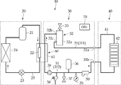
図1に示すように、この実施形態に係る温水暖房装置10は、ヒートポンプユニット20と、ヒートポンプユニット20を熱源とする温水ユニット30と、利用側の暖房端末を備えた暖房ユニット40とを備えている。
As shown in FIG. 1, the hot
ヒートポンプユニット20は、冷媒を圧縮する圧縮機21、凝縮器22、膨張弁23および蒸発器24を備え、それらを冷媒配管25で接続した冷媒回路を有している。
The
ヒートポンプユニット20は、四方弁を備えた冷房と暖房の切換が可能な可逆サイクル方式であってもよいが、本発明において、ヒートポンプユニット20は、暖房用の熱源として用いるため、可逆サイクルのため四方弁は特に必要としない。したがって、温水ユニット30の循環水を加熱する熱源となりうる最小限の機能を備えていればよく、各構成要素の具体的な構成は、仕様に応じて任意に選定されてよい。
The
ヒートポンプユニット20と温水ユニット30との間には、ヒートポンプユニット20を流れる冷媒と、温水ユニット30を流れる熱媒体としての水とを熱交換する熱交換器60が設けられている。
A
熱交換器60は、水−冷媒熱交換器であって、この実施形態において、温水ユニット30の温水循環路31の一部分に設けられている所定容積の循環水用のタンク61内に凝縮器22が収納され、タンク61内で循環水が凝縮器22により加熱されて温水が生成される。なお、図示しないが、熱交換器60を例えば二重管熱交換器としてもよい。
The
温水ユニット30は、熱交換器60で生成された温水(循環水)が循環する温水循環路31を備えている。温水循環路31は、往路側(温水送出側)の温水接続口31aと復路側(温水戻り側)の温水接続口31bを介して暖房ユニット40側の放熱回路41と接続される。
The
このように、温水循環路31の一部に、暖房ユニット40側の放熱回路41が含まれるが、以下の説明において、温水循環路31と放熱回路41を特に区別する必要がない場合には、放熱回路41を含めて温水循環路31と言う。
As described above, a part of the hot
温水循環路31のうちの熱交換器60と温水接続口31aとの間の往路側配管311には、熱交換器60で加熱された温水をさらに加熱する補助ヒータ装置32を備えている。
Outward-
補助ヒータ装置32は、上部側に温水流入口32b、下部側に温水流出口32cを有する筒状ケーシング32aを備え、図示しないが、筒状ケーシング32a内には、補助用電気ヒータが収納されている。
The
補助ヒータ装置32は、熱交換器60にて生成された温水の温度が所定温度に達していない場合に、図示しない給電電源から補助用電気ヒータに通電され、循環水の温度を所定温度にまで高める。なお、補助用電気ヒータへの通電制御は、温水ユニット30に設けられている制御部(CPU)70によって行われる。
When the temperature of the hot water generated by the
補助ヒータ装置32には、空気抜き弁33が取り付けられている。空気抜き弁33は、補助ヒータ装置32内に溜まった空気を大気中に放出するため、補助ヒータ装置32の上端に取り付けられている。
An
温水循環路31のうちの温水接続口31bと熱交換器60との復路側配管312には、ストレーナ装置50、圧力計35、膨張タンク36、圧力安全弁37、給排水弁38および循環ポンプ39がそれぞれ配置されている。
A
圧力計35は、温水循環路31内の管内圧力を測定するために用いられる。圧力計35の測定データは、制御部70に送られる。
The
膨張タンク36は、循環水の熱膨張を吸収するタンクである。圧力安全弁37は、循環水が沸騰するなどして温水循環路31内の管圧が規定値以上となった際に、管破裂を防ぐために強制的に温水循環路31を外気に開放するリリーフバルブである。
The
給排水弁38は、温水循環路31内に水を注水したり、温水循環路31内の循環水を抜き取るために設けられており、その先端には、水道管などに接続されるニップルと開閉コック(ともに図示しない)が設けられている。
The water supply /
循環ポンプ39は、温水循環路31内の循環水を一方向(この実施形態では時計回り)に循環させるためのポンプであって、制御部70により、その駆動が制御される。
The
暖房ユニット40は、往路側の温水接続口31aと復路側の温水接続口31bとを介して、温水ユニット30側の温水循環路31に接続される放熱回路41を備えている。放熱回路41には、熱源の利用側としての暖房端末42が設けられている。暖房端末42は、例えば床暖房装置やラジエータ、ファンコンベクタなどであってよい。
The
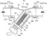
本発明の特徴は、ストレーナ装置50にある。図2に示すように、ストレーナ装置50は、例えば黄銅などの鋳造品からなる円筒状の継手管51と、継手管51に着脱自在に取り付けられるフィルタユニット52とを備えている。
A feature of the present invention resides in the
なお、この実施形態において、図1に示すように、継手管51は、復路側配管312おける例えば温水接続口31bと圧力計35との間の配管部分に介装されているが、これ以外の配管部分に介装されてもよい。往路側配管311側の配管部分であってもよい。
In this embodiment, as shown in FIG. 1, the
継手管51は、両端に接続口51a、51bを有し、これらの接続口51a、51bが、例えばフレア継手313,313とフレアナット314,314を介して復路側配管312の上流側の配管端部312aと下流側の配管端部312bとに接続され、これにより、継手管51内の流路51cには、温水循環路31内の循環水が図2に示す矢印方向(右から左)に流れる。
The
この実施形態において、フィルタユニット52は、筒状に形成された網目フィルタ55と、網目フィルタ55内に好ましくは同軸的に配置された電磁石56とを備えている。また、継手管51は、フィルタユニット52を継手管51の流路51c内に導き入れるためのフィルタ装着部53を備えている。
In this embodiment, the
この実施形態において、フィルタ装着部53は、継手管51の管壁から循環水の流れ方向に沿って斜め方向に一体として引き出された傾斜管部531と、傾斜管部531よりも下流側で継手管51の管壁からほぼ垂直に一体として引き出された垂直管部532とを含む、軸線が傾けられた分岐管状に形成されている。
In this embodiment, the
フィルタユニット52は、上流側の配管端部312a(一方の接続口51a)側から流入する循環水が、網目フィルタ55の上端開口部551から網目フィルタ55内に流れるように、傾斜管部531に沿って継手管51内に配置される。
The
この実施形態によると、継手管51のフィルタ装着部53とは反対側の管壁には、網目フィルタ55を継手管51内に配置した際、その上端開口部551の角部が当接するように凹まされた湾曲凹部511が設けられ、これにより、循環水の多くが網目フィルタ55内を通るようにしている。
According to this embodiment, when the
フィルタ装着部53の開口部には、蓋板54が例えば水密的なねじ嵌合等により着脱自在に取り付けられており、この蓋板54に、フィルタユニット52の網目フィルタ55と電磁石56とが支持されている。すなわち、フィルタユニット52は、蓋板54を介して継手管51に着脱可能である。
A
網目フィルタ55は、循環水に含まれているゴミや不純物等の異物を捕捉し得る目の細かな番手の網体からなるが、この実施形態において、網目フィルタ55は、循環水中に溶解しているカルシウム成分を析出する析出用電気ヒータとして兼用できるようにするため、その一部好ましくは全部が電熱線により形成されている。
The
電熱線には、循環水を60℃以上に加熱し得る発熱容量を有するニクロム線等が用いられるが、循環水内に浸漬されることから、防水処理が施されていることが必要である。上記したように、網目フィルタ55の全体が電熱線により網状に形成されることが好ましいが、網目フィルタ55の一部に電熱線を編み込んでもよい。なお、電熱線は、網目フィルタ55に一体的に編み込まれている必要は必ずしも無く、その内周もしくは外周に沿って配線されていればよい。
As the heating wire, a nichrome wire or the like having a heat generation capacity capable of heating the circulating water to 60 ° C. or higher is used. However, since it is immersed in the circulating water, it needs to be waterproofed. As described above, the
なお、本発明は、この実施形態とは異なり、網目フィルタ55とは別に、電熱線からなる単独として形成された析出用電気ヒータをさらに備える態様を排除するものではない。
In addition, unlike this embodiment, this invention does not exclude the aspect further equipped with the electric heater for precipitation formed separately from the heating filter separately from the
電磁石56は、棒状の鉄心561と、鉄心561の周囲に巻回される電磁コイル562とを有する一般的な電磁石であってよいが、循環水内に浸漬されることから、電磁コイル562には、上記電熱線と同じく、防水処理を施す必要がある。
The
なお、電磁コイル562は通電によって発熱する。そこで、電磁コイル562カルシウムを析出させる析出用ヒータとして用いることもできる。このような態様も本発明に含まれる。
The
この実施形態において、蓋板54には、網目フィルタ55の電熱線および電磁コイル562の図示しない各接続端子を含む電源接続部541が設けられ、この電源接続部541に、図示しない給電電源側の給電用コネクタ542が接続される。この実施形態において、電源接続部541と給電用コネクタ542は、ねじ嵌合により着脱自在となっている。
In this embodiment, the
このストレーナ装置50によれば、網目フィルタ55に編み込まれている電熱線に通電することにより、異物を除去する網目フィルタ55をカルシウム析出用のヒータとしても用いることができる。
According to the
また、電磁コイル562に通電(直流通電)して電磁石56にN,S磁極を発生させることにより、循環水中に浮遊している金属片等の磁性体を電磁石56に磁気的に吸着することができる。
Further, by energizing the electromagnetic coil 562 (direct current energization) to generate N and S magnetic poles in the
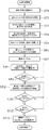
次に、図3のフローチャートを参照して、上記ストレーナ装置によるカルシウム除去手順の一例について説明する。このカルシウム除去工程は、温水暖房装置10の設置時か、もしくは、メンテナンス時に配管内の循環水を入れ替えた後に行われ、ユーザーの使用に供する本運転前に、循環水に含まれているカルシウム成分を予め除去する。
Next, an example of the calcium removal procedure by the strainer device will be described with reference to the flowchart of FIG. This calcium removal step is performed after the circulating water in the piping is replaced at the time of installation of the hot
設置時について説明すると、ヒートポンプユニット20と温水ユニット30は予め連結されているとして、温水ユニット30に暖房ユニット40を配管接続してヒートポンプユニット20、温水ユニット30および暖房ユニット40の電源を含む温水暖房装置10のすべての電源をオフとし(ステップST1)、温水ユニット30の空気抜き弁33を大気開放する(ステップST2)。
When the installation is described, assuming that the
次に、給排水弁38に図示しない給水パイプを接続し、温水循環路31内に水(例えば、水道水)を注水する(ステップST3)。その際、圧力計35を確認して、配管内が規定圧力になるまで注水をしたのち(ステップST4)、給水パイプを抜き、給排水弁38を閉じる(ステップST5)。以上により、温水循環路31内に循環水が注水される。
Next, a water supply pipe (not shown) is connected to the water supply /
注水が完了したのち、温水ユニット30の電源を投入し、カルシウム除去モードを選択する(ST6)。このとき、ヒートポンプユニット20の電源はオフであり、ヒートポンプユニット20は停止している。
After the water injection is completed, the
これにより、制御部70は、循環ポンプ39を駆動して、温水循環路31内の水を循環させ(ステップST7)、ストレーナ装置50の析出用ヒータとしての網目フィルタ55に配線された電熱線および補助用ヒータ装置32への通電を開始し、温水循環路31内の循環水を加熱する(ステップST8)。
Thereby, the
制御部70は、図示しない温度センサを介して継手管51内の循環水の水温を監視し、その水温が60℃未満で予め設定されている所定温度(例えば50℃)となったと判断すると(ステップST9)、補助用ヒータ装置32の電源をオフとし、析出用ヒータとしての網目フィルタ55の電熱線への通電を継続する(ステップST10)。
When the
継手管51内の循環水の水温が60℃以上になると、循環水に含まれているカルシウム成分(炭酸水素カルシウム:Ca(HCO3)2が網目フィルタ55の電熱線の表面に炭酸カルシウム(CaCO3)として析出し始める。
When the water temperature of the circulating water in the
そこで、制御部70は、継手管51内の循環水の水温が60℃に達したと判断すると(ステップST11)、図示しないタイマーを起動して、所定の設定時間(例えば30分)になるまで網目フィルタ55の電熱線への通電を継続する(ステップST12)。この通電時間の設定は、循環水の水量や水質等に応じて適宜決められてよい。
Therefore, when the
上記ステップ12での判定がYESで、所定の設定時間が経過すると、制御部70は、循環ポンプ39と網目フィルタ55の電熱線への通電をともにオフとして(ステップST13)、一連のカルシウム除去工程を終える。
When the determination in step 12 is YES and a predetermined set time has elapsed, the
このカルシウム除去工程は、例えばメンテナンスなどの際に、循環水を入れ替えた際にも、同様にして本運転開始前に行われる。 This calcium removal step is similarly performed before the start of the actual operation when the circulating water is replaced during maintenance or the like.
なお、上記実施形態では、補助用ヒータ装置32と網目フィルタ55の電熱線との両方に通電して、循環水の水温を析出温度域よりも低い60℃未満の所定温度まで昇温するようにしているが、当初から網目フィルタ55の電熱線のみに通電して、循環水を60℃以上に加熱するようにしてもよい。このような態様も本発明に含まれる。また、循環水を60°未満の所定温度まで昇温させるためにヒートポンプユニット20を運転してもよい。
In the above embodiment, both the
また、上記したように、電磁コイル562に通電して電磁石56にN,S磁極を発生させることにより、循環水中に浮遊している金属片等の磁性体を電磁石56に磁気的に吸着することができるが、電磁コイル562への通電は、カルシウム除去工程中に行われてもよいし、カルシウム除去前もしくはカルシウム除去後に行われてもよい。
Further, as described above, by energizing the
また、フィルタユニット52は、管継手51に着脱可能であるため、この温水暖房装置の設置後もしくはメンテナンス後に、網目フィルタ55や電磁石56の清掃を容易に行うことができる。
Moreover, since the
10 温水暖房装置
20 ヒートポンプユニット
21 圧縮機
22 凝縮器
23 膨張弁
24 蒸発器
30 温水ユニット
31 温水循環路
32 補助用ヒータ装置
33 エア抜き弁
35 圧力計
36 膨張タンク
37 給排水弁
38 圧力安全弁
39 循環ポンプ
40 暖房ユニット
41 放熱回路
42 暖房端末
50 ストレーナ装置
51 継手管
52 フィルタユニット
53 フィルタ装着部
54 蓋板
55 網目フィルタ
56 電磁石
561 鉄心
562 電磁コイル
60 熱交換器
70 制御部
DESCRIPTION OF
Claims (6)
上記循環水を60℃以上に加熱して、水中に溶解しているカルシウム成分を析出して除去するための析出用電気ヒータを備えていることを特徴とするストレーナ装置。 In the strainer device having a mesh filter that captures foreign matters such as dust and impurities contained in the circulating water in the hot water circulation path,
A strainer device comprising a deposition electric heater for heating the circulating water to 60 ° C. or more to deposit and remove calcium components dissolved in the water.
上記温水ユニットの上記温水循環路内には、請求項1ないし4のいずれか1項に記載のストレーナ装置と、上記温水循環路内の循環水を循環させる循環ポンプとが組み込まれており、上記ストレーナ装置が備える上記析出用電気ヒータおよび上記循環ポンプを制御する制御部を備え、
上記制御部は、上記ヒートポンプユニットが休止しているとき、上記循環ポンプを駆動して上記温水循環路内に循環水を循環させた状態で、上記析出用電気ヒータに通電して少なくとも上記ストレーナ装置内の循環水を60℃以上に加熱して、循環水中に溶解しているカルシウム成分を上記析出用電気ヒータの周りに析出させることを特徴とする温水暖房装置。 A hot water unit having a hot water circuit, a heat pump unit as a heat source for heating the circulating water in the hot water circuit to a predetermined temperature, and a heating unit having a heat dissipation circuit included in a part of the hot water circuit. In the hot water heater
The strainer device according to any one of claims 1 to 4 and a circulation pump for circulating the circulating water in the warm water circulation path are incorporated in the warm water circulation path of the warm water unit, The deposition electric heater provided in the strainer device and a controller for controlling the circulation pump,
When the heat pump unit is at rest, the control unit drives the circulation pump to circulate the circulating water in the hot water circulation path, and energizes the precipitation electric heater to at least the strainer device. A hot water heating apparatus characterized in that the circulating water inside is heated to 60 ° C. or higher, and the calcium component dissolved in the circulating water is deposited around the electric heater for precipitation.
Priority Applications (1)
| Application Number | Priority Date | Filing Date | Title |
|---|---|---|---|
| JP2014042779A JP2015167883A (en) | 2014-03-05 | 2014-03-05 | Strainer device and hot water heating system |
Applications Claiming Priority (1)
| Application Number | Priority Date | Filing Date | Title |
|---|---|---|---|
| JP2014042779A JP2015167883A (en) | 2014-03-05 | 2014-03-05 | Strainer device and hot water heating system |
Publications (1)
| Publication Number | Publication Date |
|---|---|
| JP2015167883A true JP2015167883A (en) | 2015-09-28 |
Family
ID=54201151
Family Applications (1)
| Application Number | Title | Priority Date | Filing Date |
|---|---|---|---|
| JP2014042779A Pending JP2015167883A (en) | 2014-03-05 | 2014-03-05 | Strainer device and hot water heating system |
Country Status (1)
| Country | Link |
|---|---|
| JP (1) | JP2015167883A (en) |
Cited By (2)
| Publication number | Priority date | Publication date | Assignee | Title |
|---|---|---|---|---|
| JP6400256B1 (en) * | 2017-12-06 | 2018-10-03 | 三菱電機株式会社 | Water circulation device construction method and scale removal device |
| EP3627059A1 (en) * | 2018-09-21 | 2020-03-25 | Panasonic Intellectual Property Management Co., Ltd. | Warm water circulation device with magnetic filter |
-
2014
- 2014-03-05 JP JP2014042779A patent/JP2015167883A/en active Pending
Cited By (4)
| Publication number | Priority date | Publication date | Assignee | Title |
|---|---|---|---|---|
| JP6400256B1 (en) * | 2017-12-06 | 2018-10-03 | 三菱電機株式会社 | Water circulation device construction method and scale removal device |
| WO2019111343A1 (en) * | 2017-12-06 | 2019-06-13 | 三菱電機株式会社 | Water circulation device construction method and scale removal device |
| EP3712510A4 (en) * | 2017-12-06 | 2021-01-27 | Mitsubishi Electric Corporation | CONSTRUCTION PROCESS FOR A WATER CIRCULATION DEVICE AND SCALE REMOVAL DEVICE |
| EP3627059A1 (en) * | 2018-09-21 | 2020-03-25 | Panasonic Intellectual Property Management Co., Ltd. | Warm water circulation device with magnetic filter |
Similar Documents
| Publication | Publication Date | Title |
|---|---|---|
| CN204806675U (en) | Heat pump hot water supply system | |
| JP2003343925A (en) | Liquid discharge device | |
| JP2015167883A (en) | Strainer device and hot water heating system | |
| JP2015161437A (en) | Hot water heating device and hot water heating device | |
| JP6128332B2 (en) | Hot water heater | |
| KR100786938B1 (en) | Solar boiler | |
| CN102297505A (en) | Hot-water feeder and hot-water supply system | |
| JP5567948B2 (en) | Heat source equipment | |
| JP2008170027A (en) | Hot water storage tank | |
| JP6115754B2 (en) | Heat source machine and freeze prevention control method | |
| JP2010190466A (en) | Water heater | |
| KR101339659B1 (en) | Water heating apparatus of water purifier and controling method of the same | |
| JP5904723B2 (en) | Heat exchange system | |
| CN207299108U (en) | Water unit anti-freezing system | |
| JP5842597B2 (en) | Hot water storage water heater | |
| CN213739041U (en) | A mobile cooling water purification treatment device | |
| JP2014085066A (en) | Water treatment equipment, humidifier and water heater | |
| JP6615555B2 (en) | Hot water supply system and method of operating hot water supply system | |
| CN210740541U (en) | Energy-concerving and environment-protective central heating device | |
| JP3702055B2 (en) | Heat source machine for hot water heater | |
| JP2006194583A (en) | Heat pump type hot water supply apparatus | |
| CN121953536A (en) | Air source heat pump unit | |
| CN113375344A (en) | Water heater and water circulation control method | |
| CN115193582A (en) | Horizontal magnetic filter | |
| JP3819923B2 (en) | Heat pump type water heater |