EP3626563A1 - Soupape de commande, système de freinage à commande électronique ainsi que procédé de commande du système de freinage à commande électronique - Google Patents
Soupape de commande, système de freinage à commande électronique ainsi que procédé de commande du système de freinage à commande électronique Download PDFInfo
- Publication number
- EP3626563A1 EP3626563A1 EP18195253.2A EP18195253A EP3626563A1 EP 3626563 A1 EP3626563 A1 EP 3626563A1 EP 18195253 A EP18195253 A EP 18195253A EP 3626563 A1 EP3626563 A1 EP 3626563A1
- Authority
- EP
- European Patent Office
- Prior art keywords
- control
- pressure
- valve
- brake
- service brake
- Prior art date
- Legal status (The legal status is an assumption and is not a legal conclusion. Google has not performed a legal analysis and makes no representation as to the accuracy of the status listed.)
- Granted
Links
- 238000000034 method Methods 0.000 title claims description 11
- 230000001419 dependent effect Effects 0.000 claims abstract description 14
- 239000012528 membrane Substances 0.000 claims description 15
- 230000007547 defect Effects 0.000 claims description 14
- 230000009471 action Effects 0.000 claims description 7
- 230000006835 compression Effects 0.000 claims description 7
- 238000007906 compression Methods 0.000 claims description 7
- 238000011144 upstream manufacturing Methods 0.000 claims description 7
- 238000009423 ventilation Methods 0.000 claims description 4
- 238000013022 venting Methods 0.000 claims description 3
- 238000013461 design Methods 0.000 claims description 2
- 238000001514 detection method Methods 0.000 claims 2
- 230000006870 function Effects 0.000 description 29
- 230000000694 effects Effects 0.000 description 20
- 238000011161 development Methods 0.000 description 6
- 230000018109 developmental process Effects 0.000 description 6
- 230000036316 preload Effects 0.000 description 6
- 230000003321 amplification Effects 0.000 description 4
- 238000003199 nucleic acid amplification method Methods 0.000 description 4
- 230000000903 blocking effect Effects 0.000 description 3
- 230000008901 benefit Effects 0.000 description 2
- 230000005540 biological transmission Effects 0.000 description 2
- 230000008859 change Effects 0.000 description 2
- 238000006073 displacement reaction Methods 0.000 description 2
- 230000009467 reduction Effects 0.000 description 2
- 238000013519 translation Methods 0.000 description 2
- 230000000740 bleeding effect Effects 0.000 description 1
- 238000006243 chemical reaction Methods 0.000 description 1
- 238000010276 construction Methods 0.000 description 1
- 230000003247 decreasing effect Effects 0.000 description 1
- 230000003993 interaction Effects 0.000 description 1
- 238000005259 measurement Methods 0.000 description 1
- 238000007789 sealing Methods 0.000 description 1
- 230000035807 sensation Effects 0.000 description 1
- 230000008054 signal transmission Effects 0.000 description 1
- 238000012549 training Methods 0.000 description 1
Images


Classifications
-
- B—PERFORMING OPERATIONS; TRANSPORTING
- B60—VEHICLES IN GENERAL
- B60T—VEHICLE BRAKE CONTROL SYSTEMS OR PARTS THEREOF; BRAKE CONTROL SYSTEMS OR PARTS THEREOF, IN GENERAL; ARRANGEMENT OF BRAKING ELEMENTS ON VEHICLES IN GENERAL; PORTABLE DEVICES FOR PREVENTING UNWANTED MOVEMENT OF VEHICLES; VEHICLE MODIFICATIONS TO FACILITATE COOLING OF BRAKES
- B60T13/00—Transmitting braking action from initiating means to ultimate brake actuator with power assistance or drive; Brake systems incorporating such transmitting means, e.g. air-pressure brake systems
- B60T13/10—Transmitting braking action from initiating means to ultimate brake actuator with power assistance or drive; Brake systems incorporating such transmitting means, e.g. air-pressure brake systems with fluid assistance, drive, or release
- B60T13/66—Electrical control in fluid-pressure brake systems
- B60T13/68—Electrical control in fluid-pressure brake systems by electrically-controlled valves
- B60T13/683—Electrical control in fluid-pressure brake systems by electrically-controlled valves in pneumatic systems or parts thereof
-
- B—PERFORMING OPERATIONS; TRANSPORTING
- B60—VEHICLES IN GENERAL
- B60T—VEHICLE BRAKE CONTROL SYSTEMS OR PARTS THEREOF; BRAKE CONTROL SYSTEMS OR PARTS THEREOF, IN GENERAL; ARRANGEMENT OF BRAKING ELEMENTS ON VEHICLES IN GENERAL; PORTABLE DEVICES FOR PREVENTING UNWANTED MOVEMENT OF VEHICLES; VEHICLE MODIFICATIONS TO FACILITATE COOLING OF BRAKES
- B60T15/00—Construction arrangement, or operation of valves incorporated in power brake systems and not covered by groups B60T11/00 or B60T13/00
- B60T15/02—Application and release valves
- B60T15/04—Driver's valves
-
- B—PERFORMING OPERATIONS; TRANSPORTING
- B60—VEHICLES IN GENERAL
- B60T—VEHICLE BRAKE CONTROL SYSTEMS OR PARTS THEREOF; BRAKE CONTROL SYSTEMS OR PARTS THEREOF, IN GENERAL; ARRANGEMENT OF BRAKING ELEMENTS ON VEHICLES IN GENERAL; PORTABLE DEVICES FOR PREVENTING UNWANTED MOVEMENT OF VEHICLES; VEHICLE MODIFICATIONS TO FACILITATE COOLING OF BRAKES
- B60T13/00—Transmitting braking action from initiating means to ultimate brake actuator with power assistance or drive; Brake systems incorporating such transmitting means, e.g. air-pressure brake systems
- B60T13/10—Transmitting braking action from initiating means to ultimate brake actuator with power assistance or drive; Brake systems incorporating such transmitting means, e.g. air-pressure brake systems with fluid assistance, drive, or release
- B60T13/58—Combined or convertible systems
- B60T13/588—Combined or convertible systems both fluid and mechanical assistance or drive
-
- B—PERFORMING OPERATIONS; TRANSPORTING
- B60—VEHICLES IN GENERAL
- B60T—VEHICLE BRAKE CONTROL SYSTEMS OR PARTS THEREOF; BRAKE CONTROL SYSTEMS OR PARTS THEREOF, IN GENERAL; ARRANGEMENT OF BRAKING ELEMENTS ON VEHICLES IN GENERAL; PORTABLE DEVICES FOR PREVENTING UNWANTED MOVEMENT OF VEHICLES; VEHICLE MODIFICATIONS TO FACILITATE COOLING OF BRAKES
- B60T13/00—Transmitting braking action from initiating means to ultimate brake actuator with power assistance or drive; Brake systems incorporating such transmitting means, e.g. air-pressure brake systems
- B60T13/10—Transmitting braking action from initiating means to ultimate brake actuator with power assistance or drive; Brake systems incorporating such transmitting means, e.g. air-pressure brake systems with fluid assistance, drive, or release
- B60T13/24—Transmitting braking action from initiating means to ultimate brake actuator with power assistance or drive; Brake systems incorporating such transmitting means, e.g. air-pressure brake systems with fluid assistance, drive, or release the fluid being gaseous
- B60T13/26—Compressed-air systems
- B60T13/38—Brakes applied by springs or weights and released by compressed air
- B60T13/385—Control arrangements therefor
-
- B—PERFORMING OPERATIONS; TRANSPORTING
- B60—VEHICLES IN GENERAL
- B60T—VEHICLE BRAKE CONTROL SYSTEMS OR PARTS THEREOF; BRAKE CONTROL SYSTEMS OR PARTS THEREOF, IN GENERAL; ARRANGEMENT OF BRAKING ELEMENTS ON VEHICLES IN GENERAL; PORTABLE DEVICES FOR PREVENTING UNWANTED MOVEMENT OF VEHICLES; VEHICLE MODIFICATIONS TO FACILITATE COOLING OF BRAKES
- B60T13/00—Transmitting braking action from initiating means to ultimate brake actuator with power assistance or drive; Brake systems incorporating such transmitting means, e.g. air-pressure brake systems
- B60T13/10—Transmitting braking action from initiating means to ultimate brake actuator with power assistance or drive; Brake systems incorporating such transmitting means, e.g. air-pressure brake systems with fluid assistance, drive, or release
- B60T13/66—Electrical control in fluid-pressure brake systems
- B60T13/662—Electrical control in fluid-pressure brake systems characterised by specified functions of the control system components
-
- B—PERFORMING OPERATIONS; TRANSPORTING
- B60—VEHICLES IN GENERAL
- B60T—VEHICLE BRAKE CONTROL SYSTEMS OR PARTS THEREOF; BRAKE CONTROL SYSTEMS OR PARTS THEREOF, IN GENERAL; ARRANGEMENT OF BRAKING ELEMENTS ON VEHICLES IN GENERAL; PORTABLE DEVICES FOR PREVENTING UNWANTED MOVEMENT OF VEHICLES; VEHICLE MODIFICATIONS TO FACILITATE COOLING OF BRAKES
- B60T13/00—Transmitting braking action from initiating means to ultimate brake actuator with power assistance or drive; Brake systems incorporating such transmitting means, e.g. air-pressure brake systems
- B60T13/74—Transmitting braking action from initiating means to ultimate brake actuator with power assistance or drive; Brake systems incorporating such transmitting means, e.g. air-pressure brake systems with electrical assistance or drive
- B60T13/741—Transmitting braking action from initiating means to ultimate brake actuator with power assistance or drive; Brake systems incorporating such transmitting means, e.g. air-pressure brake systems with electrical assistance or drive acting on an ultimate actuator
-
- B—PERFORMING OPERATIONS; TRANSPORTING
- B60—VEHICLES IN GENERAL
- B60T—VEHICLE BRAKE CONTROL SYSTEMS OR PARTS THEREOF; BRAKE CONTROL SYSTEMS OR PARTS THEREOF, IN GENERAL; ARRANGEMENT OF BRAKING ELEMENTS ON VEHICLES IN GENERAL; PORTABLE DEVICES FOR PREVENTING UNWANTED MOVEMENT OF VEHICLES; VEHICLE MODIFICATIONS TO FACILITATE COOLING OF BRAKES
- B60T15/00—Construction arrangement, or operation of valves incorporated in power brake systems and not covered by groups B60T11/00 or B60T13/00
- B60T15/02—Application and release valves
- B60T15/025—Electrically controlled valves
- B60T15/027—Electrically controlled valves in pneumatic systems
-
- B—PERFORMING OPERATIONS; TRANSPORTING
- B60—VEHICLES IN GENERAL
- B60T—VEHICLE BRAKE CONTROL SYSTEMS OR PARTS THEREOF; BRAKE CONTROL SYSTEMS OR PARTS THEREOF, IN GENERAL; ARRANGEMENT OF BRAKING ELEMENTS ON VEHICLES IN GENERAL; PORTABLE DEVICES FOR PREVENTING UNWANTED MOVEMENT OF VEHICLES; VEHICLE MODIFICATIONS TO FACILITATE COOLING OF BRAKES
- B60T15/00—Construction arrangement, or operation of valves incorporated in power brake systems and not covered by groups B60T11/00 or B60T13/00
- B60T15/02—Application and release valves
- B60T15/04—Driver's valves
- B60T15/041—Driver's valves controlling auxiliary pressure brakes, e.g. parking or emergency brakes
-
- B—PERFORMING OPERATIONS; TRANSPORTING
- B60—VEHICLES IN GENERAL
- B60T—VEHICLE BRAKE CONTROL SYSTEMS OR PARTS THEREOF; BRAKE CONTROL SYSTEMS OR PARTS THEREOF, IN GENERAL; ARRANGEMENT OF BRAKING ELEMENTS ON VEHICLES IN GENERAL; PORTABLE DEVICES FOR PREVENTING UNWANTED MOVEMENT OF VEHICLES; VEHICLE MODIFICATIONS TO FACILITATE COOLING OF BRAKES
- B60T7/00—Brake-action initiating means
- B60T7/12—Brake-action initiating means for automatic initiation; for initiation not subject to will of driver or passenger
- B60T7/20—Brake-action initiating means for automatic initiation; for initiation not subject to will of driver or passenger specially for trailers, e.g. in case of uncoupling of or overrunning by trailer
-
- F—MECHANICAL ENGINEERING; LIGHTING; HEATING; WEAPONS; BLASTING
- F16—ENGINEERING ELEMENTS AND UNITS; GENERAL MEASURES FOR PRODUCING AND MAINTAINING EFFECTIVE FUNCTIONING OF MACHINES OR INSTALLATIONS; THERMAL INSULATION IN GENERAL
- F16K—VALVES; TAPS; COCKS; ACTUATING-FLOATS; DEVICES FOR VENTING OR AERATING
- F16K31/00—Actuating devices; Operating means; Releasing devices
- F16K31/12—Actuating devices; Operating means; Releasing devices actuated by fluid
- F16K31/42—Actuating devices; Operating means; Releasing devices actuated by fluid by means of electrically-actuated members in the supply or discharge conduits of the fluid motor
-
- B—PERFORMING OPERATIONS; TRANSPORTING
- B60—VEHICLES IN GENERAL
- B60T—VEHICLE BRAKE CONTROL SYSTEMS OR PARTS THEREOF; BRAKE CONTROL SYSTEMS OR PARTS THEREOF, IN GENERAL; ARRANGEMENT OF BRAKING ELEMENTS ON VEHICLES IN GENERAL; PORTABLE DEVICES FOR PREVENTING UNWANTED MOVEMENT OF VEHICLES; VEHICLE MODIFICATIONS TO FACILITATE COOLING OF BRAKES
- B60T2270/00—Further aspects of brake control systems not otherwise provided for
- B60T2270/40—Failsafe aspects of brake control systems
- B60T2270/402—Back-up
-
- B—PERFORMING OPERATIONS; TRANSPORTING
- B60—VEHICLES IN GENERAL
- B60T—VEHICLE BRAKE CONTROL SYSTEMS OR PARTS THEREOF; BRAKE CONTROL SYSTEMS OR PARTS THEREOF, IN GENERAL; ARRANGEMENT OF BRAKING ELEMENTS ON VEHICLES IN GENERAL; PORTABLE DEVICES FOR PREVENTING UNWANTED MOVEMENT OF VEHICLES; VEHICLE MODIFICATIONS TO FACILITATE COOLING OF BRAKES
- B60T2270/00—Further aspects of brake control systems not otherwise provided for
- B60T2270/40—Failsafe aspects of brake control systems
- B60T2270/413—Plausibility monitoring, cross check, redundancy
-
- B—PERFORMING OPERATIONS; TRANSPORTING
- B60—VEHICLES IN GENERAL
- B60T—VEHICLE BRAKE CONTROL SYSTEMS OR PARTS THEREOF; BRAKE CONTROL SYSTEMS OR PARTS THEREOF, IN GENERAL; ARRANGEMENT OF BRAKING ELEMENTS ON VEHICLES IN GENERAL; PORTABLE DEVICES FOR PREVENTING UNWANTED MOVEMENT OF VEHICLES; VEHICLE MODIFICATIONS TO FACILITATE COOLING OF BRAKES
- B60T2270/00—Further aspects of brake control systems not otherwise provided for
- B60T2270/40—Failsafe aspects of brake control systems
- B60T2270/414—Power supply failure
Definitions
- the invention relates to a control valve for controlling a spring brake pressure according to the preamble of claim 1, as well as an electronically controllable brake system with such a control valve and a method for controlling the electronically controllable brake system.
- Conventional electronically controllable brake systems have pressure modulators which are assigned to the individual vehicle axles and are electrically controlled in normal operation in order to implement a specific service brake specification on the respective wheels in a service brake circuit.
- the electrical control takes place here from a central module which controls the respective pressure modulators via a control signal in accordance with the service brake braking specification.
- the pressure modulators are conventionally provided with pneumatic redundancy.
- a service brake valve which receives the service brake application from the driver, can transmit a pneumatic control pressure to pneumatic redundancy connections of the respective pressure modulators.
- these provide an increase in the air volume of the control pressure and a control of a brake pressure on the respective service brakes. This enables pneumatic redundancy to be implemented.
- brake systems of this type also have a parking brake circuit in which a parking brake braking specification can be received by the driver via a parking brake valve.
- a parking brake control pressure is output from the parking brake valve to a control valve and above it air-volume-increased on spring-loaded parts of the wheel brakes, preferably the rear-axle wheel brakes, as spring-loaded brake pressure.
- the spring-loaded parts are constructed in such a way that they apply the wheel brakes with a spring preload when the spring-loaded brake pressure is low and are opened against the spring preload when the spring-loaded brake pressure is higher.
- a braking effect can be achieved via a diaphragm part depending on the diaphragm brake pressure output by the rear axle pressure modulator - electrically or pneumatically redundant - and via the spring-loaded part depending on the spring-loaded brake pressure.
- pressure modulators which can be controlled pneumatically, are required to form the pneumatic redundancy on the rear axle.
- these are technically complex and, on the other hand, a lot of effort is required to lay pressure lines to the rear axle, which are only required for redundancy.
- WO 2014/161671 A1 and US 2014 / 0103237A1 a combination of a relay valve and a parking brake valve upstream of the relay valve is described, which are arranged separately from one another and can influence one another.
- a spring-loaded part of a wheel brake can be controlled via the relay valve in accordance with a parking brake braking specification.
- a supply pressure or an atmospheric pressure can be specifically specified for the parking brake valve, with which the relay valve is then activated.
- an initial pulse is first carried out and sent to the relay valve, and the cycle for ventilation and bleeding is then continued.
- the pressure setpoint is reached much faster than with pulses of constant cycle time and constant duty cycle.
- the object of the invention is therefore to provide a control valve for controlling a spring-loaded brake pressure with which a comfortable, reliable and simple pneumatic control of an electrically controllable brake system can be made possible even in the event of redundancy.
- Another object is to provide an electrically controllable braking system and a method for controlling this braking system.
- the subclaims indicate preferred further training.
- a control valve for controlling a spring-loaded brake pressure on spring-loaded parts of a rear-axle wheel brake in such a way that, in addition to the pneumatic control via a parking brake control pressure output by a parking brake valve, a pneumatic control of the control valve with a by a first control input Service brake valve output and service brake control pressure that is dependent on a service brake brake specification is possible, the first control input being connectable to this, in particular in the case of redundancy, with an adjustable first control chamber, the first control chamber being arranged via a first control piston in such a manner with those arranged in the control valve
- Control means is operatively connected to the fact that the spring brake pressure at the work outlet when the first control chamber or the first control piston is adjusted as a result of pressurization with the service brake control pressure is adjustable depending on the service brake control pressure and / or the parking brake control pressure.
- the advantage is already achieved that the spring-loaded parts can not only be actuated in a customary manner as a function of a parking brake application, but also as a function of a service brake application specified via a service brake valve.
- the control valve according to the invention thus ensures that in addition to the parking brake control pressure, the service brake control pressure is also converted into a corresponding spring-loaded brake pressure, so that a redundant actuation of the rear axle wheel brakes - in this case via the spring-loaded part - can advantageously take place.
- the redundant pneumatic control of a rear axle pressure modulator can therefore be dispensed with.
- the rear axle pressure modulator can be constructed in a simpler manner since only an electrical control is required. For pneumatic redundancy on the rear axle, components of the parking brake or the parking brake circuit can then be used, which already have pneumatic components and enable pneumatic control.
- the modulation of the spring brake pressure dependent on the service brake braking specification can be controlled or modulated. Accordingly, the adjustment of the first control piston and thus of the first control chamber can be influenced in a targeted manner by additionally using the third control chamber, since the first pressure force from the first control chamber is counteracted starting from the third control chamber.
- the bypass valve by appropriately switching the bypass valve, it can first be determined whether the spring brake pressure is to be influenced directly or strongly by the service brake control pressure by decoupling the third control chamber. In this case, only the first control room has an influence on the operation or the setting of the control valve. By appropriately switching the bypass valve, however, a slightly weakened influence can also be achieved by connecting the third control room to the first control room. Then the operation of the control valve is less influenced by a combination of both control rooms, since part of the first pressure force is canceled by the second pressure force.
- the control valve according to the invention can thus advantageously define a characteristic or a translation with a plurality of actuation ranges, which describes which spring-loaded brake pressure results from a specific service brake control pressure as a result of a service brake braking specification.
- the first control chamber is separated from the third control chamber by a first wall connected to the first control piston and the service brake control pressure in the first control chamber acts on a first surface of the first wall and the service brake control pressure depending on the switching position of the bypass -Valve in the third Control room acts on a second surface of the first wall.
- the first surface is larger than the second surface, so that when the first control chamber is pressurized with the service brake control pressure, a first pressure force acts on the first control piston in the first direction that is greater than a second pressure force on the first control piston in the second direction with simultaneous pressurization of the third control chamber with the same service brake control pressure.
- the area ratios can thus be used to selectively set the direction in which the first control piston moves when the pressure changes and how strongly this movement takes place, i.e. how much the spring brake pressure increases with a certain increase in the service brake control pressure. This enables the braking effect to be set in a targeted manner.
- a piston element is arranged on the second surface of the first wall, the piston element projecting through the third control chamber in such a way that the second surface on the first wall is reduced, the second pressure force on the first control piston when the third brake chamber is pressurized with the service brake control pressure, it is only effected by the action of the service brake control pressure on the second surface reduced by the piston element.
- bypass valve can be switched as a function of a predetermined limit pressure in the first control chamber, the first control chamber being connected to the third control chamber via the bypass valve when the service brake control pressure is applied when the first control chamber is pressurized Service brake control pressure exceeds the specified limit pressure, and the first control chamber is not connected to the third control chamber via the bypass valve when the service brake control pressure falls below the specified limit pressure.
- the limit pressure can be set between 0.5 bar and 0.7 bar.
- a corresponding spring-loaded brake pressure is controlled by the control valve, which, due to the spring characteristic of the spring-loaded part of the rear axle wheel brakes, does not lead to any or only a slight change in the braking effect due to an idle travel. If the service brake control pressure exceeds the limit pressure, a braking effect is achieved due to the spring brake pressure which is thereby controlled.
- the service brake control pressure acts on the first control piston only from the first control chamber, ie no weakened adjustment of the first control piston he follows. As a result, when the service brake valve is actuated, the driver quickly feels a reaction which correlates with the actuation of the brake pedal.
- the bypass valve can be switched under pressure control, so that no further electronic components and logic modules are necessary.
- the bypass valve has a bypass control piston, wherein the bypass control piston can be adjusted as a function of a bypass control pressure acting in a bypass control chamber and as a function of a changeover pressure acting in a bypass pressure chamber of the bypass valve, the changeover pressure corresponding to the pressure in the first control chamber and the bypass control piston with different areas in the bypass control chamber and the bypass pressure chamber such that the bypass control pressure is in the opposite direction to the changeover pressure on the bypass control piston acts.
- the bypass valve is therefore changed depending on the actual service brake specification.
- bypass control piston lifts off an inlet seat as soon as the changeover pressure exceeds the limit pressure and the first control chamber is thereby connected to the third control chamber.
- bypass control chamber is connected to the working outlet of the control valve via a bypass control input in order to supply the spring brake pressure as a bypass control pressure.
- control means are formed by an adjustable second control chamber and an adjustable second control piston, wherein the parking brake control pressure can be admitted into the second control chamber via the second control input and the second control piston by the action of the parking brake control pressure is adjustable on the second control piston in a first direction and / or a second direction opposite to the first direction.
- a simple piston adjustment can thus be achieved, which can be used for increasing the air quantity of the parking brake control pressure for setting the spring brake pressure.
- the control means in the control valve thus ensure that, depending on the parking brake control pressure, a specific spring-loaded brake pressure is set at the working outlet of the control valve, which corresponds to a conventional air quantity amplification in the parking brake circuit.
- the respective service brake control pressure let into the first control chamber can influence the spring-loaded brake pressure and thus, depending on this, a pneumatically redundant actuation of the rear axle wheel brakes can take place.
- the second control chamber is delimited by a third wall arranged on the adjustable second control piston, the third wall being movable relative to the valve housing in such a way that the second control piston adjusts to the third wall by the action of the parking brake control pressure can be.
- the first control piston is operatively connected to the second control piston in such a way that the second control piston is carried along at least in regions by adjusting the first control piston.
- an effective connection is advantageously created with simple means between the control means of the control valve, which ensure implementation of the parking brake, and the adjustable first control chamber, which is influenced by the respective service brake control pressure.
- the service brake control pressure can provide an adjustment of the spring-loaded brake pressure by using the control means of the control valve, so that a simple structure of the control valve is achieved with this additional functionality (pneumatic redundancy).
- the first control piston and the second control piston can be firmly connected to one another so that no relative movement between the two control pistons is permitted.
- the first control piston in its lower region, is immersed with a first shaft in a hollow cylindrical second shaft of the second control piston.
- the diameter of the first shaft is reduced in some areas in the area of a shaft narrowing of the second shaft.
- the first control piston can move relative to the second control piston in a certain range. This range is defined in such a way that the second control piston can be moved in the non-redundant braking mode without being influenced by the first control piston.
- the first control chamber is delimited by a first wall that is movable with respect to a valve housing and by a second wall that is fixed to or fixed to the valve housing, the first control piston being connected to the first wall in such a way that the first control piston and the second control piston, which is operatively connected to it, are pushed in a first direction by increasing the pressure in the first control chamber.
- the second control chamber is preferably arranged relative to the first control chamber in such a way that the second control piston and the first control piston that is operatively connected to it are pushed in the second direction when the pressure in the second control chamber rises when the first control chamber and / or the third control chamber with the Atmosphere.
- the second control chamber - like the first control chamber - is likewise delimited by the second wall fixed to the valve housing, the second control piston being located at one Pressure increase in the second control chamber away from the second wall in the second direction and the first control piston in the case of a pressure increase in the first control chamber away from the second wall in the first direction.
- This opposite mobility can be achieved by simple means when the pressure is increased.
- the first control chamber and the second control chamber interact with one another via the control pistons in such a way that a spring-loaded brake pressure is established at the work outlet, which is dependent on the parking brake control pressure prevailing in the second control chamber and / or that in the first control chamber prevailing service brake control pressure, in particular depending on which brake presetting assigned to the control pressures is the higher.
- self-regulation takes place advantageously through the control valve, i.e. Actual braking of the vehicle via the spring-loaded parts of the rear axle wheel brakes, e.g. in the parked state with a corresponding parking brake specification, it cannot be overwritten by a redundantly specified service brake specification, which specifies a lower braking effect.
- a redundantly specified service brake specification which specifies a lower braking effect.
- the service brake application will be implemented if this leads to a greater braking effect than the metered parking brake application.
- an axially movable valve body preloaded by a compression spring is further provided as the control means, the working output depending on the axial adjustment of the valve body either via a pressure chamber with a vent connection to reduce the spring brake pressure or with a supply connection Increasing the spring brake pressure is connectable, the second control piston the valve body can adjust axially depending on the parking brake control pressure and / or the service brake control pressure. This enables a simple adjustment of the spring brake pressure depending on the respective control pressure.
- the control valve interacts with a switchable changeover valve in such a way that the first control chamber can be connected to a service brake valve for specifying a service brake control pressure in the first control room or with an atmosphere can be connected for venting the first control chamber, the changeover valve being integrated in the control valve or being connected upstream of the first control input of the control valve. Only then is the respective service brake control pressure fed into the first control chamber and can act indirectly on the control means. In a further switching position of the changeover valve, it can be achieved that the atmosphere is connected to the first control room for venting the first control room. This is the case if the service brake control pressure should not have any influence on the spring brake pressure, i.e. especially when the brake system is functioning normally and therefore no redundant pneumatic control of the rear axle wheel brakes is required.
- an electronically controllable braking system is also provided, the front axle wheel brakes, rear axle wheel brakes with a spring-loaded part and a membrane part, an electropneumatically controllable front axle pressure modulator for outputting a front axle brake pressure to the front axle wheel brakes, and an electronically controllable rear axle pressure modulator for output a membrane brake pressure on the membrane parts of the rear axle wheel brakes, a central module and an electro-pneumatic service brake valve, the service brake valve being designed to output an electric service brake actuation signal to the central module as a function of a service brake braking specification, the central module being connected in a signal-conducting manner to the front axle pressure modulator and the rear axle pressure modulator for transmitting control signals dependent on the service brake actuation signal to the pressure modulators, wherein the service brake valve is further designed to output a pneumatic service brake control pressure as a function of the service brake specification, the front axle pressure modulator being controllable via a redundancy connection with a front axle service brake control pressure in
- control valve for setting the spring-loaded brake pressure is the control valve described in accordance with the invention, the service brake valve being pneumatically connectable to a first control input of the control valve for transmitting the service brake control pressure to the control valve and for setting a spring-loaded brake pressure on the spring-loaded parts of the rear axle wheel brakes depending on the parking brake control pressure and / or the service brake control pressure.
- the central module is signal-leading with an integrated control valve or upstream of the first control input Switchover valve is connected for the optional connection of the service brake valve with the first control chamber of the control valve or the atmosphere with the first control chamber of the control valve, whereby in normal operation without a defect or a failure in the electrical control of the rear axle pressure modulator, it can be specified via a switchover signal transmitted to the switchover valve is that the atmosphere is connected to the first control room and otherwise the service brake valve is connected to the first control room.
- the function of the control valve according to the invention can advantageously be used for redundant braking operation via the spring-loaded parts.
- the service brake valve is of single-channel design and the front axle control pressure supplied to the front axle pressure modulator from the service brake valve can also be fed via a branch to the first control input of the control valve, or the service brake valve is designed with two channels, a first channel with the redundancy connection the front axle pressure modulator is connected to the pneumatic control of the front axle pressure modulator with the front axle service brake control pressure and a second channel is connected to the first control input of the control valve for transmitting a redundancy control pressure generated in the service brake valve to the control valve.
- the service brake control pressure corresponding to the service brake brake specification can be predetermined in a simple manner to the control valve in order to be able to implement the service brake brake specification redundantly via the spring-loaded parts.
- the single-channel version has the advantage that the service brake valve can be made simpler and cheaper, since only one channel is required.
- the two-channel version enables the front axle and the rear axle to be braked pneumatically and redundantly independently of one another if necessary.
- the bypass valve in the control valve is switched as a function of a defined limit pressure in the first control chamber, the first control chamber being connected to the third control chamber via the bypass valve when the service brake is applied to the first control chamber when pressure is applied.
- Control pressure, the service brake control pressure exceeds the specified limit pressure, and the first control chamber is not connected to the third control chamber via the bypass valve if the service brake control pressure falls below the specified limit pressure.
- the central module specifies to the changeover valve in normal operation without detecting an electrical defect or a failure in the electrical actuation of the rear axle wheel brakes by the membrane part that the first control chamber is connected to the atmosphere. This can be determined that the function of the control valve should not be influenced during normal operation of the brake system.
- FIG. 1 A vehicle combination of a towing vehicle 100 and a trailer 200 attached to it is shown.
- the towing vehicle 100 has an at least partially electrically controllable two-circuit brake system 1, the front and rear axle wheel brakes 2, 3 of which can be actuated by manual actuation of a service brake valve 4 and a parking brake valve 5.
- a front axle brake pressure p2 corresponding to the specification can be built up on the front axle wheel brakes 2 in an electrically or pneumatically controlled manner.
- a front axle service brake control pressure pV is applied to the pneumatic part of the service brake valve 4 depending on the level of the service brake braking specification VB
- Front axle pressure control module 6 transmitted via a pneumatic redundancy connection 6a.
- a front axle control signal S2 is transmitted to the front axle pressure control module 6 electronically by a central module 7.
- the front axle control signal S2 is formed from a service brake actuation signal S4, which is output by the electronic part of the service brake valve 4 as a function of the service brake specification VB to the central module 7 and processed further therein.
- the central module 7 can, for example, carry out an axle load distribution or other higher-level functions and generate the front axle control signal S2 as a function thereof.
- a front axle brake pressure p2 is generated in the front axle pressure modulator 6 for the front axle wheel brakes 2, which leads to braking of the towing vehicle 100 according to the service brake braking specification VB and possibly the higher-level functions.
- the front axle brake pressure p2 can be modified via additional ABS control valves 9, which are arranged in front of the front axle wheel brakes 2. This can counteract a blocking or impending blocking of the front wheels 2a ascertained via wheel speed sensors 10.
- the ABS control valves 9 are controlled from the central module 7, in which a corresponding intelligent ABS control logic is integrated.
- the front axle wheel brakes 2 are actuated electrically via the central module 7. If the electronic control fails the front axle pressure modulators 6 for any reason, for example because the signal transmission between the central module 7 and the front axle pressure modulator 6 is interrupted and / or the central module 7 and / or the front axle pressure modulator 6 has a failure in the electrical level, so the front axle wheel brakes 2 can also be pneumatically controlled via the pneumatic redundancy connection 6a depending on the pneumatic front axle service brake control pressure pV.
- the front axle service brake control pressure pV output by the service brake valve 4 is correspondingly amplified in the front axle pressure modulator 6 and output to the front axle wheel brakes 2 as the front axle brake pressure p2. This forms a pneumatically controlled fallback level for the front axle wheel brakes 2, so that the towing vehicle 100 can still be braked safely via the front wheels 2a even in the event of electrical failures.
- the rear axle wheel brakes 3 for braking the rear wheels 3a are designed as a combined spring-loaded diaphragm cylinder, i.e. they have a spring storage part 3b and a membrane part 3c.
- a diaphragm brake pressure p3c can be predefined by a rear axle pressure modulator 11 in a pressure-reduced manner from a second pressure medium supply 8b in order to actuate the diaphragm part 3c of the rear axle wheel brakes 3.
- the rear axle pressure modulator 11 differs from the front axle pressure modulator 6 in that no redundancy connection is provided for a pneumatic control. Accordingly, the rear axle pressure modulator 11 can only be controlled electrically, as is also the case with the front axle pressure modulator 6.
- the rear axle pressure modulator 11 is constructed in a manner comparable to the electrical level of the front axle pressure modulator 6, so that via the central module 7 as a function of the service brake braking specification VB output rear axle control signal S3 from the rear axle pressure modulator 11 via an inlet-outlet valve combination, a corresponding membrane brake pressure p3c can be generated and output.
- An anti-lock adjustment of the diaphragm brake pressure p3c depending on the measurement of the speed sensors 10 on the rear wheels 3a takes place on the rear axle without additional ABS control valves already in the rear axle pressure modulator 11. In this respect, the diaphragm brake pressure p3c is already adjusted by the ABS function.
- the rear axle pressure modulator 11 in contrast to the front axle pressure modulator 6, has no pneumatic redundancy, provision is made according to the invention to provide pneumatic redundancy via the spring storage part 3b of the rear axle wheel brakes 3.
- the spring-loaded part 3b functions in such a way that the wheel brakes 3 are automatically applied when the spring-loaded brake pressure p3b acting on the spring-loaded part 3b is reduced, or the braking effect on the rear wheels 3a increases. If the spring-loaded brake pressure p3b is increased, the spring-loaded part 3b is opened further against a spring preload and a braking effect on the rear wheels 3a is thereby reduced or completely eliminated.
- the spring storage parts 3b of the rear axle wheel brakes 3 are used for a parking brake function in the vehicle 100, which is controlled via the parking brake valve 5 in a parking brake circuit. Accordingly, if the driver specifies a specific parking brake braking request VP via the pneumatic parking brake valve 5, the corresponding parking brake control pressure p5 is output by the parking brake valve 5 and transmitted to a second control input 12b of a control valve 12.
- the control valve 12 provides an air quantity increase of the parking brake control pressure p5, so that a spring brake pressure p3b via a working outlet 12c (see FIG. Fig. 2 ) to the spring storage part 3b Rear axle wheel brake 3 is output, which leads to a braking of the vehicle 100 corresponding to the parking brake braking request VP.
- the driver uses the parking brake brake request VP to specify that the vehicle should be parked, i.e. the full braking effect is to be achieved via the spring-loaded parts 3b, the line between the parking brake valve 5 and the control valve 12 is vented, so that a parking brake control pressure p5 corresponding to the atmospheric pressure is present at the second control input 12b of the control valve 12.
- the spring preload thus ensures that the spring-loaded parts 3b are tightened. If the parking brake valve 5 is in a travel position or any intermediate position, a correspondingly high parking brake control pressure p5 is predetermined from the third pressure medium supply 8c to the second control input 12b, so that the spring-loaded parts 3b are continuously opened against the spring preload via the spring-loaded brake pressure p3b will.
- the control valve 12 is expanded in accordance with the invention in a first step in such a way that, in addition to the parking brake function described, a redundant pneumatic control of the rear axle wheel brakes 3 - in this case via the spring-loaded part 3b - can also take place. This takes place in particular when the rear axle pressure modulator 11 and / or the central module 7 and / or the electrical connection therebetween has an electrical defect or failure, that is to say braking of the rear wheels 3a can no longer take place electrically controlled by the central module 7.
- the front axle service brake control pressure pV output by the pneumatic part of the service brake valve 4 during manual braking is fed via a branch 13 and a switching valve 26 to a first control input 12a of the control valve 12, the control valve 12 being one inverse to the front-axle service brake control pressure pV and air-filled spring brake pressure p3b generated and via the working outlet 12c (see Fig. 2 ) outputs to the spring-loaded part 3b of the wheel brakes 3.
- the air quantity amplification of the parking brake control pressure p5 and of the front axle service brake control pressure pV takes place in the control valve 12 through a pressure supply from the third pressure medium supply 8c.
- the control valve 12 can also be provided to supply the control valve 12 via the switching valve 26, instead of the front axle service brake control pressure pV, with a redundancy service brake control pressure pR corresponding to the service brake braking specification VB, which pressure pressure pV is generated in the service brake valve 4 and is comparable to the front axle service brake control pressure pV is issued.
- the service brake valve 4 is then constructed in two channels, the front axle service brake control pressure pV for pneumatically actuating the front axle pressure modulator 6 being generated via a first channel K1 and the redundancy service brake control pressure pB for pneumatically actuating the control valve 12 via a second channel K2 be issued.
- the front axle service brake control pressure pV for pneumatically actuating the front axle pressure modulator 6 being generated via a first channel K1
- the redundancy service brake control pressure pB for pneumatically actuating the control valve 12 via a second channel K2 be issued.
- this optional embodiment is shown schematically by a further dashed channel K2 on the service brake valve 4 and a pneumatic control line from the service brake valve 4 to the line leading to the first control input 12a of the control valve 12.
- the supply of the front-axle service brake control pressure pV via the branch 13 to the switching valve 26 is then omitted.
- only the redundant actuation of the control valve 12 via the front-axle service brake control pressure pV is described, which corresponds in a corresponding manner to the redundancy - Service brake control pressure pR can be transmitted.
- the control valve 12 additionally takes on the task of inversion and air volume amplification of the front axle service brake control pressure pV, so that a redundant one is added pneumatic control of the rear axle wheel brakes 3 can take place.
- the control valve 12 is designed in accordance with this embodiment in such a way that the implementation of the parking brake specification VP or the air quantity increase of the parking brake control pressure p5 takes priority over the inversion and air quantity amplification of the front axle service brake control pressure pV has.
- pneumatic control of the control valve 12 with the front-axle service brake control pressure pV only leads to output of a corresponding spring-loaded brake pressure p3b to the spring-loaded part 3b if electrical control via the rear-axle pressure modulator 11 and a corresponding output of the membrane brake pressure p3c fails. Otherwise, transmission of the front-axle service brake control pressure pV to the control valve 12 via the first control input 12a has no effect on the spring-loaded part 3b of the rear-axle wheel brakes 3.
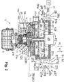
- control valve 12 is provided.
- the control valve 12 consists of the control inputs 12a, 12b, via which the front axle service brake control pressure pV or the redundancy service brake control pressure pR or the parking brake control pressure p5 are specified, and the working output 12c, which the spring-loaded brake pressure p3b outputs to the spring-loaded part 3b.
- a supply connection 12d is provided, which is connected to the third pressure medium supply 8c and provides the pressure medium to the control valve 12.
- the control valve 12 can be connected to the atmosphere A via a vent connection 12e.
- the control valve 12 also has three control chambers 14a, 14b, 14c and two control pistons 15a, 15b as functional elements, the two control pistons 15a, 15b being operatively connected to one another and, as described in more detail, can take one another at least in certain areas in certain situations.
- An axial movement of the two control pistons 15a, 15b enables a pressure chamber 16 of the control valve 12 to be connected to the supply connection 12d or the ventilation connection 12e.
- the pressure chamber 16 is also connected to the working outlet 12c, so that depending on the axial position of the two control pistons 15a, 15b, a pressure increase (over 12d) or a pressure reduction (over 12e) of the spring-loaded brake pressure p3b present at the working outlet 12c can take place.
- a first control piston 15a is connected to a first wall 17a and is axially displaceably mounted in an opening 18 in a second fixed wall 17b of the control valve 12.
- the opening 18 is sealed like the first wall 17a, so that a first control chamber 14a is formed between the first wall 17a and the second wall 17b and a valve housing 12f of the control valve 12, which is caused by an axial displacement of the first control piston 15a and thus connected first wall 17a can be enlarged and reduced.
- the first control chamber 14a is connected to the first control input 12a of the control valve 12 in order to be able to conduct the pressure medium with the front axle service brake control pressure pV into the first control chamber 14a.
- the connection between the first control chamber 14a and the first control input 12a or the service brake valve 4 and the first control input 12a can be specifically blocked via a switching valve 26, for example an electrically controllable 3/2-way valve.
- the switching valve 26 is either arranged as part of the control valve 12 between the first control input 12a and the first control chamber 14a or is - as well in Fig. 1 provided - upstream of the control valve 12 or the first control input 12a.
- Fig. 2 a 3/2-way valve upstream of the control valve 12 is shown schematically as a switching valve 26.
- the function of the switching valve 26 described below can be transferred in an analogous manner to the switching valve 26 integrated in the control valve 12.
- the pressure medium with the front axle service brake control pressure pV or the redundancy service brake control pressure pR is fed from the service brake valve 4 to the shift valve 26 via a first switching valve input 26a.
- a second switching valve input 26b is connected to atmosphere A.
- the pressure medium with the front axle service brake control pressure pV or the redundancy service brake control pressure pR or the atmospheric pressure can be output to the first control chamber 14a via a switching valve output 26c.
- the switching valve 26 can be switched in an electrically controlled manner in order to release or block the front axle service brake control pressure pV.
- the switching valve 26 is connected to the central module 7 in a signal-conducting manner.
- the central module 7 gives the command to switch the switching valve 26 in normal operation without an electrical fault being present via a switching signal S1.
- the switching valve 26 is preferably switched over each time the brake is actuated, ie whenever there is a specific service brake braking specification VB on the service brake valve 4 .
- the switching takes place in such a way that admission of the front axle service brake control pressure pV into the first control chamber 14a is blocked when the brake is applied. Instead, the first control chamber 14a is connected to the atmosphere A by the position of the switching valve 26.
- the first control chamber 14a is under atmospheric pressure, so that when the brake is actuated in normal operation it is achieved that the front-axle service brake control pressure pV does not influence the function of the control valve 12.
- the switching valve 26 is of this type switched that the pressure medium with the front-axle service brake control pressure pV is admitted into the first control chamber 14a via the first control input 12a.
- the service brake valve 4 specifies an atmospheric pressure in the unactuated position, the first control chamber 14a is also connected to the atmosphere A, so that the control valve 12 is not influenced thereby either.
- the central module 7 fails or there is another electrical fault in the rear axle pressure modulator 11 or when the rear axle pressure modulator 11 is activated, no switchover signal S1 is transmitted to the switching valve 26 when the brake is actuated.
- the switching valve 26 is then automatically switched such that the front axle service brake control pressure pV, which is then greater than the atmospheric pressure, is admitted into the first control chamber 14a via the switching valve output 26c even when the brake is actuated.
- the function of the control valve 12 can thus, as described further below, be influenced by the front axle service brake control pressure pV if there is an electrical failure or defect.
- a third control chamber 14c is also defined above the first wall 17a and below the valve housing 12f. This can be connected to the first control chamber 14a via a bypass valve 27 in order to enable a certain predetermined behavior of the control valve 12 in the redundant braking mode when the front-axle service brake control pressure pV is let into the first control chamber 14a.
- This is implemented as follows: The first control chamber 14a of the control valve 12 is connected via a first connecting channel 27b to a bypass pressure chamber 27a, so that the pressure medium located in the first control chamber 14a also reaches the bypass pressure chamber 27a.
- the bypass pressure chamber 27a is in the in Fig.
- bypass valve 27 shown opened first switching position B1 of the bypass valve 27 via a second connecting channel 27c also connected to the third control chamber 14c, so that the pressure medium located in the first control chamber 14a also reaches the third control chamber 14c.
- the bypass valve 27 also has a bypass control piston 27d, which is adjusted in the first direction R1 by a bypass spring 27e, as a result of which the bypass control piston 27d in the open first switching position B1 of the bypass valve 27 from an inlet seat 27f takes off. This creates the connection between the first and the third control chamber 14a, 14c.
- the bypass control piston 27d can be adjusted in a pressure-controlled manner against the spring force of the bypass spring 27e in that a correspondingly high bypass control pressure p27 is let into a bypass control chamber 27g via a bypass control input 27i.
- the bypass control input 27i is connected to the working output 12c of the control valve 12, so that the spring-loaded brake pressure p3b also acts as a bypass control pressure p27 in the bypass control chamber 27g.
- bypass control piston 27d is also adjusted against a changeover pressure pU acting from below on the bypass control piston 27d in the bypass pressure chamber 27a, the changeover pressure pU being the pressure acting in the first control chamber 14a of the control valve 12 (atmospheric pressure or front axle service brake Control pressure pV or redundancy service brake control pressure pR).
- the pressure force caused by the bypass control pressure p27 in the bypass control chamber 27g acts on the upper region of the bypass control piston 27d against the spring force of the bypass spring 27e and the pressure force caused by the switching pressure pU in the first control chamber 14a on the lower region of the Bypass spool 27d.
- bypass control piston 27d reaches the inlet seat 27f with correspondingly set force relationships, the connection between the first control chamber 14a and the third control chamber 14c is interrupted.
- the bypass valve 27 is then in the closed second switching position S2.
- the bypass control piston 27d is relieved via a bypass outlet 27k.
- the bypass valve 27 is tuned in such a way that the bypass control piston 27d in the case of an unactuated parking brake valve 5, i.e. with a high spring brake pressure p3b or bypass control pressure p27 of, for example, 8.5 bar, and in non-redundant braking operation, i.e. with a functioning central module 7 and atmospheric pressure in the first control chamber 14a, at the inlet seat 27f.
- the bypass spring 27e is thus fully tensioned.
- the control valve 12 is therefore not influenced by the first control piston 15a in the non-redundant braking mode.
- the first control piston 15a projects through them. In its lower region, the first control piston 15a dips with a first shaft 19a into a hollow cylindrical second shaft 19b of the second control piston 15b. The diameter of the first shaft 19a is reduced in some areas in the area of a shaft constriction 20 of the second shaft 19b. As a result, the first control piston 15a can move relative to the second control piston 15b within a certain range.
- This range is defined in such a way that the second control piston 15b can be moved in the non-redundant braking mode on the basis of the parking brake braking specification VP, without this first control piston 15a to be influenced, for example by friction of the seals.
- both control pistons 15a, 15b move together, as explained in more detail below.
- the second control chamber 14b is connected to the second control input 12b, so that the parking brake control pressure p5 present at the second control input 12b also acts in the second control chamber 14b.
- the second control piston 15b is displaced axially upwards in a first direction R1 or downwards in a second direction R2 via the third wall 17c (in the non-redundant braking mode independently of the first control piston 15a).
- the second control piston 15b can be adjusted upward in the first direction R1 here either due to an intake (with a low parking brake control pressure p5) from the second control chamber 14b or by a spring (not shown) which, in the vented state, moves the second control piston 15b into the first direction R1 pushes.
- the second control input 12b is initially vented, so that a parking brake control pressure p5 corresponding to the atmospheric pressure is present in the second control chamber 14b.
- a parking brake control pressure p5 corresponding to the atmospheric pressure is present in the second control chamber 14b.
- the second control piston 15b is adjusted axially upwards due to the low pressure effect on the third wall 17c.
- the pressure chamber 16 is connected to the vent connection 12e and the working outlet 12c is also vented, ie there is a low spring-loaded brake pressure p3b, so that the spring-loaded parts 3b of the rear-axle wheel brakes 3 are clamped by the spring preload.
- bypass control piston 27d is moved upward by the bypass spring 27e, since the bypass control pressure p27 is too low to act against the spring force.
- the first and in the third control chamber 14a, 14c there are the same pressures, the atmospheric pressure being permanently present due to the switching position of the switching valve 26 in the non-redundant braking mode.
- the first control piston 15a and the second control piston 15b are therefore not influenced by this.
- the second control piston 15b is pressed axially downward via the third wall 17c until the lower region thereof reaches a valve body 22 in a sealing manner from a certain axial adjustment, so that the connection between the working outlet 12c and the ventilation connection 12e via the pressure chamber 16 compared to the state in Fig. 2 is separated.
- the pressure chamber 16 is then only connected to the working outlet 12c.
- the spring brake pressure p3b is maintained.
- the first control piston 15a is not taken along, since the shaft constriction 20 is adjusted between the two contact surfaces 21a, 21b of the first shaft 19a which has not been moving to date.
- the second control piston 15b presses the valve body 22 downward against the force of a compression spring 23, as a result of which a passage 24 opens, so that a connection is established between the supply connection 12d and the working outlet 12c via the pressure chamber 16 .
- the spring-loaded brake pressure p3b increases and the spring-loaded part 3b is opened against the spring force, so that the rear-axle wheel brakes 3 have no or less braking effect.
- the shaft constriction 20 does not come against the lower contact surface 21a of the first shaft 19a until a maximum parking brake control pressure p5 is reached, so that the first control piston 15a is not carried along when the pressure increases to the maximum parking brake control pressure p5.
- the bypass control piston 27d is adjusted as described against the force of the bypass spring 27e in the second direction R2 due to the pressure increase, so that the connection between the two control spaces 14a, 14c is slowly separated until the bypass control piston 27d rests on the inlet seat 27f .
- the atmospheric pressure continues to prevail via the brake valve 4 (first control chamber 14a) and a non-return valve 29 (third control chamber 14c), so that the braking effect is still not influenced occurs.
- the control function just described ie the connection of the vent connection 12e to the working outlet 12c for tightening the spring-loaded part 3b or the connection of the supply connection 12d to the working outlet, can be carried out 12c for opening the spring-loaded part 3b can also be done by changing the pressure in the first control chamber 14a.
- the switchover signal S1 fails (redundant braking mode), as already indicated above:
- a pressure increase in the first control chamber 14a as a result of a redundant braking request brings about an axial displacement of the first control piston 15a in the first direction R1 upwards.
- the second control piston 15b is also pulled in the first direction R1 as soon as the lower contact surface 21b of the first shaft 19a bears against the shaft constriction 20 from below due to the pressure increase in the first control chamber 14a. This is the case, for example, when there is no actuation of the parking brake valve 5 and thus a high pressure in the second control chamber 14b or a lower actuation when there is a redundant braking request via the service brake valve 4 via the parking brake valve 5 (parking brake specification VP) than via the service brake valve 4 (service brake specification VB).
- the front axle service brake control pressure pV can be inverted because, when the front axle service brake control pressure pV is high, the second control piston 15b lifts off the valve body 22 when it is carried along by the first control piston 15a, and the working outlet 12c thus with the bleed port 12e is connected and thus the spring-loaded parts 3b can be clamped via a low spring brake pressure p3b.
- the volume in the first control chamber 14a becomes smaller, so that a connection between the working outlet 12c and the supply connection 12d is established as a result of an axial downward adjustment of the two control pistons 15a, 15b in the second direction R2 , which leads to an increasing spring-loaded brake pressure p3b and thus to a release of the spring-loaded parts 3b of the rear axle wheel brakes 3.
- an opposite adjustment of the second control piston 15a, 15b can be effected if the service brake control pressure pV or the parking brake control pressure p5 are increased.
- control valve 12 can be used to ensure that, despite a redundant service brake braking specification VB (no changeover signal S1), a corresponding parking brake braking specification VP actually results in the vehicle 100 being braked or held in the parked state, for example.
- the working outlet 12c would have to be connected to the supply connection 12d to release the spring-loaded parts 3b. That is, the first control piston 15a would have to for an axial movement of the second control piston 15b down in Fig. 2 to care.
- the second control piston 15b Conversely, if there is no parking brake specification VP, the second control piston 15b is moved axially downward in normal operation, so that a maximum spring brake pressure p3b acts.
- the front axle service brake control pressure pV prevailing in the first control chamber 14a in the event of a redundant service brake braking specification VB (no changeover signal S1) then pulls the first control piston 15a against this axial movement and also the second control piston 15b via the lower contact surface 21b and the shaft constriction 20 To a certain extent again upwards, so that the spring brake pressure p3b is reduced again and partial tightening of the spring memory parts 3b is achieved.
- the forces acting on the two control pistons 15a, 15b due to the prevailing control pressures p5, pV thus overlap, so that a corresponding braking effect is achieved by the spring-loaded parts 3b.
- the effect of a specific front axle service brake control pressure pV on the spring-loaded parts 3b in the event of pneumatic redundancy can be set in a targeted manner by the bypass valve 27.
- the front axle service brake control pressure pV only acts in the first control chamber 14a at values which are lower than the limit pressure pG, while the third control chamber 14c is under atmospheric pressure.
- a first pressure force X1 acts in the first direction R1 on the first control piston 15a, so that the front-axle service brake control pressure pV is converted directly into an inverted spring-loaded brake pressure p3b.
- the limit pressure pG can, for example, be set to between 0.5 bar and 0.7 bar, wherein when this limit pressure pG is set as the front-axle service brake control pressure pV, the control valve 12 controls a spring-loaded brake pressure p3b which corresponds to a release pressure pL of the spring-loaded parts 3b corresponds to the rear axle wheel brakes 3.
- the release pressure pL indicates from which spring-loaded brake pressure p3b the spring-loaded parts 3b actually open and thus develop a braking effect.
- the release pressure pL results from the spring characteristic of the respective spring-loaded part 3b and an independent travel dependent on it. These can vary for different spring-loaded brakes, which is why the limit pressure pG can also vary.
- the movement of the first control piston 15a is therefore dependent on the front axle service brake control pressure pV and the area ratio between a first surface F1 of the first wall 17a facing the first control chamber 14a and a second surface F2 of the first wall 17a facing the third control chamber 14c.
- an additional piston element 28 is provided in the third control chamber 14c, which is connected to the first control piston 15a or the first wall 17a and that the second surface F2 on which the front axle service brake control pressure pV in the second direction R2 can work, downsized.
- the slope is lower due to the pressure forces X1, X2 acting from below and above on the first control piston 15a than for front axle service brake control pressures pV, which are lower than the limit pressure pG. Due to the volume of the piston element 28, for pV> pG the translation between the front axle service brake control pressure pV and the modulated spring brake pressure p3b im redundant braking operation can be set in a targeted manner and thus pressure modulation of the spring brake pressure p3b takes place.
- a clearly defined control valve characteristic can thus be specified in order to improve the braking sensation in the event of redundancy.
- the first and third control chambers 14a, 14c are connected to a check valve 29 opening towards the first control chamber 14a.
- a trailer control valve 25 Via a trailer control valve 25 (see Fig. 1 ) an electrical and / or pneumatic transmission of the front axle service brake control pressure pV and the parking brake control pressure p5 or an electric trailer control signal ST can take place in the usual manner in order to be able to brake the trailer 200 as well.
- Fig. 4 can be achieved that a method first checks whether the central module 7 has a defect and / or the connection to the rear axle pressure modulator 11 has a defect and thus an electrical control of the rear axle wheel brakes 3 is not possible (St0). If this is not the case, the switching valve 26 is specified in a first alternative step St1a via the switchover signal S1 that the introduction of the front axle service brake control pressure pV or the redundancy service brake control pressure pR into the first control chamber 14a is prevented. The first control room 14a and also the third control room 14c are thus connected to the atmosphere A. and do not affect the implementation of the parking brake specification VP.
- the switchover signal S1 remains off and in a second alternative step St1b the front axle service brake control pressure pV or the redundancy service brake control pressure pR is admitted into the first control chamber 14a .
- a braking effect corresponding to the front axle service brake control pressure pV or the redundancy service brake control pressure pR is implemented as described via the spring-loaded parts 3b, with the spring-loaded brake pressure p3b as a function of a switching position B1, B2 of a bypass valve 27 in the control valve 12, different pressure forces X1, X2 acting on the first control piston 15a depending on the switching position B1, B2 of the bypass valve 27.
Priority Applications (3)
| Application Number | Priority Date | Filing Date | Title |
|---|---|---|---|
| EP18195253.2A EP3626563B1 (fr) | 2018-09-18 | 2018-09-18 | Soupape de commande, système de freinage à commande électronique ainsi que procédé de commande du système de freinage à commande électronique |
| US16/572,916 US10967843B2 (en) | 2018-09-18 | 2019-09-17 | Control valve, electronically controllable brake system and method for controlling the electronically controllable brake system |
| CN201910874512.3A CN110901621B (zh) | 2018-09-18 | 2019-09-17 | 控制阀、能电子控制的制动系统及用于控制该系统的方法 |
Applications Claiming Priority (1)
| Application Number | Priority Date | Filing Date | Title |
|---|---|---|---|
| EP18195253.2A EP3626563B1 (fr) | 2018-09-18 | 2018-09-18 | Soupape de commande, système de freinage à commande électronique ainsi que procédé de commande du système de freinage à commande électronique |
Publications (2)
| Publication Number | Publication Date |
|---|---|
| EP3626563A1 true EP3626563A1 (fr) | 2020-03-25 |
| EP3626563B1 EP3626563B1 (fr) | 2021-01-27 |
Family
ID=63642753
Family Applications (1)
| Application Number | Title | Priority Date | Filing Date |
|---|---|---|---|
| EP18195253.2A Active EP3626563B1 (fr) | 2018-09-18 | 2018-09-18 | Soupape de commande, système de freinage à commande électronique ainsi que procédé de commande du système de freinage à commande électronique |
Country Status (3)
| Country | Link |
|---|---|
| US (1) | US10967843B2 (fr) |
| EP (1) | EP3626563B1 (fr) |
| CN (1) | CN110901621B (fr) |
Families Citing this family (3)
| Publication number | Priority date | Publication date | Assignee | Title |
|---|---|---|---|---|
| DE102015011296A1 (de) * | 2015-09-02 | 2017-03-02 | Wabco Gmbh | Elektronisch steuerbares pneumatisches Bremssystem in einem Nutzfahrzeug sowie Verfahren zum elektronischen Steuern eines pneumatischen Bremssystems |
| EP3626564B1 (fr) * | 2018-09-18 | 2021-02-24 | WABCO Europe BVBA | Soupape de commande, système de freinage à commande électronique ainsi que procédé de commande du système de freinage à commande électronique |
| EP4321397A1 (fr) * | 2022-08-12 | 2024-02-14 | ZF CV Systems Europe BV | Module de frein de stationnement avec soupape de relais et piston de sécurité |
Citations (5)
| Publication number | Priority date | Publication date | Assignee | Title |
|---|---|---|---|---|
| EP1571061A1 (fr) * | 2004-03-05 | 2005-09-07 | WABCO GmbH & CO. OHG | Système de freinage pneumatique à commande électrique pour un véhicule |
| DE102008031327A1 (de) * | 2008-07-02 | 2010-04-29 | Knorr-Bremse Systeme für Nutzfahrzeuge GmbH | Elektromechanisches Bremssystem |
| US20140103237A1 (en) | 2011-05-13 | 2014-04-17 | Knorr-Bremse Systeme für Nutzfahrzeuge GmbH | Parking brake device |
| WO2014161671A1 (fr) | 2013-04-05 | 2014-10-09 | Knorr-Bremse Systeme für Nutzfahrzeuge GmbH | Système de frein de stationnement |
| WO2018041386A1 (fr) * | 2016-08-31 | 2018-03-08 | Wabco Gmbh | Système de freinage pneumatique à commande électronique dans un véhicule utilitaire, et procédé de commande électronique d'un système de freinage pneumatique dans un véhicule utilitaire |
Family Cites Families (9)
| Publication number | Priority date | Publication date | Assignee | Title |
|---|---|---|---|---|
| DE1980549U (de) * | 1967-12-22 | 1968-03-07 | Westinghouse Bremsen Apparate | Relaisventil fuer bremsanlagen. |
| US6247764B1 (en) * | 1999-04-22 | 2001-06-19 | Haldex Brake Corporation | Full function valve for heavy duty semi-trailer brake systems |
| US6769744B2 (en) * | 2000-05-25 | 2004-08-03 | Bendix Commercial Vehicle Systems Llc | Spring brake modulating relay valve |
| US7204563B2 (en) * | 2004-10-12 | 2007-04-17 | Meritor Wabco Vehicle Control Systems | Park brake interlock and trailer brake valve assembly |
| US8297713B2 (en) * | 2007-04-18 | 2012-10-30 | Meritor Wabco Vehicle Control Systems | Full function tractor protection valve |
| DE102014108558A1 (de) * | 2014-06-18 | 2015-12-24 | Knorr-Bremse Systeme für Nutzfahrzeuge GmbH | Doppelkolbenrelaisventil mit Anti-Compound-Funktion |
| DE102014112014A1 (de) * | 2014-08-22 | 2016-02-25 | Knorr-Bremse Systeme für Nutzfahrzeuge GmbH | Verfahren zum Steuern einer Betriebsbremseinrichtung eines Fahrzeugs sowie Betriebsbremsventileinrichtung für eine solche Betriebsbremseinrichtung |
| DE102016010464A1 (de) * | 2016-08-31 | 2018-03-01 | Wabco Gmbh | Elektronisch steuerbares pneumatisches Bremssystem in einem Nutzfahrzeug sowie Verfahren zum elektronischen Steuern eines pneumatischen Bremssystems in einem Nutzfahrzeug |
| EP3626564B1 (fr) * | 2018-09-18 | 2021-02-24 | WABCO Europe BVBA | Soupape de commande, système de freinage à commande électronique ainsi que procédé de commande du système de freinage à commande électronique |
-
2018
- 2018-09-18 EP EP18195253.2A patent/EP3626563B1/fr active Active
-
2019
- 2019-09-17 US US16/572,916 patent/US10967843B2/en active Active
- 2019-09-17 CN CN201910874512.3A patent/CN110901621B/zh active Active
Patent Citations (5)
| Publication number | Priority date | Publication date | Assignee | Title |
|---|---|---|---|---|
| EP1571061A1 (fr) * | 2004-03-05 | 2005-09-07 | WABCO GmbH & CO. OHG | Système de freinage pneumatique à commande électrique pour un véhicule |
| DE102008031327A1 (de) * | 2008-07-02 | 2010-04-29 | Knorr-Bremse Systeme für Nutzfahrzeuge GmbH | Elektromechanisches Bremssystem |
| US20140103237A1 (en) | 2011-05-13 | 2014-04-17 | Knorr-Bremse Systeme für Nutzfahrzeuge GmbH | Parking brake device |
| WO2014161671A1 (fr) | 2013-04-05 | 2014-10-09 | Knorr-Bremse Systeme für Nutzfahrzeuge GmbH | Système de frein de stationnement |
| WO2018041386A1 (fr) * | 2016-08-31 | 2018-03-08 | Wabco Gmbh | Système de freinage pneumatique à commande électronique dans un véhicule utilitaire, et procédé de commande électronique d'un système de freinage pneumatique dans un véhicule utilitaire |
Also Published As
| Publication number | Publication date |
|---|---|
| CN110901621A (zh) | 2020-03-24 |
| US10967843B2 (en) | 2021-04-06 |
| US20200086840A1 (en) | 2020-03-19 |
| EP3626563B1 (fr) | 2021-01-27 |
| CN110901621B (zh) | 2022-01-28 |
Similar Documents
| Publication | Publication Date | Title |
|---|---|---|
| EP3507154B1 (fr) | Systeme de frein pneumatique a reglage electrique et methode de reglage | |
| EP3600991B1 (fr) | Frein à main électro-pneumatique avec tcv integré (commande scandinave) | |
| EP2707260B1 (fr) | Dispositif frein de stationnement | |
| EP2240352B1 (fr) | Système de frein de parking | |
| DE102009045191C5 (de) | Verfahren zum Betrieb einer Bremseinrichtung für ein hydraulisch gebremstes Zugfahrzeug | |
| EP1000830B1 (fr) | Ajusteur de commande de frein à redondance d'addition intégrée | |
| EP1188634B2 (fr) | Soupape de frein de remorque pour remorques à commande de freinage électronique et à sécurité améliorée de remorque stationnée | |
| EP2163447B1 (fr) | Installation de frein actionnée par un moyen de pression d'un véhicule doté d'un dispositif de frein fixe produisant une pression contraire pour des freins de remorque | |
| EP3678909B1 (fr) | Dispositif electropneumatique de commande de frein de stationnement et systeme de freinage de vehicule | |
| EP2133250B1 (fr) | Agencement de soupape de frein de stationnement pour un système de freinage d'un véhicule utilitaire | |
| WO2009083108A2 (fr) | Frein de stationnement | |
| DE102014118943A1 (de) | Verfahren zur Steuerung einer elektropneumatischen Parkbremseinrichtung mit dynamischer Blockierverhinderung | |
| EP3626563B1 (fr) | Soupape de commande, système de freinage à commande électronique ainsi que procédé de commande du système de freinage à commande électronique | |
| EP3626564B1 (fr) | Soupape de commande, système de freinage à commande électronique ainsi que procédé de commande du système de freinage à commande électronique | |
| EP3784540B1 (fr) | Soupape de commande, système de freinage à commande électronique et procédé de commande du système de freinage à commande électronique | |
| EP3010772B1 (fr) | Dispositif de commande permettant de commander les freins d'une combinaison entre un véhicule tracteur et une remorque | |
| EP3694755A1 (fr) | Module de freinage de stationnement électropneumatique pour véhicules utilitaires comprenant des freins de stationnement à ressort accumulateur | |
| DE19918070B4 (de) | Druckregelvorrichtung für elektro-pneumatische Bremsanlagen von Fahrzeugen, insbesondere Nutzfahrzeugen | |
| EP3277551B1 (fr) | Dispositif à air comprimé pour des véhicules équipés d'une soupape à double relais | |
| DE19933483C1 (de) | Druckmittelbetätigte Fahrzeugbremsanlage | |
| WO2016169972A1 (fr) | Dispositif de soupape de commande pour dispositif de frein de stationnement pour véhicules à moteur et dispositif de frein de stationnement pour véhicules à moteur | |
| DE20122549U1 (de) | Anhängerbremsventil für Anhängefahrzeuge mit elektronischer Bremsregelung und erweiterter Sicherheit des geparkten Anhängers | |
| DE10139757A1 (de) | Anhängerbremsventil für Anhängefahrzeuge mit elektronischer Bremsregelung und erweiterter Sicherheit des geparkten Anhängers | |
| EP1069016B2 (fr) | Installation de freinage actionnée par moyen de pression | |
| DE102014116732A1 (de) | Bremseinrichtung eines Fahrzeugs mit elektrischer und durch eine pneumatische Notzuspanneinrichtung zuspannbarer Feststellbremse |
Legal Events
| Date | Code | Title | Description |
|---|---|---|---|
| PUAI | Public reference made under article 153(3) epc to a published international application that has entered the european phase |
Free format text: ORIGINAL CODE: 0009012 |
|
| STAA | Information on the status of an ep patent application or granted ep patent |
Free format text: STATUS: THE APPLICATION HAS BEEN PUBLISHED |
|
| AK | Designated contracting states |
Kind code of ref document: A1 Designated state(s): AL AT BE BG CH CY CZ DE DK EE ES FI FR GB GR HR HU IE IS IT LI LT LU LV MC MK MT NL NO PL PT RO RS SE SI SK SM TR |
|
| AX | Request for extension of the european patent |
Extension state: BA ME |
|
| STAA | Information on the status of an ep patent application or granted ep patent |
Free format text: STATUS: REQUEST FOR EXAMINATION WAS MADE |
|
| 17P | Request for examination filed |
Effective date: 20200925 |
|
| RBV | Designated contracting states (corrected) |
Designated state(s): AL AT BE BG CH CY CZ DE DK EE ES FI FR GB GR HR HU IE IS IT LI LT LU LV MC MK MT NL NO PL PT RO RS SE SI SK SM TR |
|
| GRAP | Despatch of communication of intention to grant a patent |
Free format text: ORIGINAL CODE: EPIDOSNIGR1 |
|
| STAA | Information on the status of an ep patent application or granted ep patent |
Free format text: STATUS: GRANT OF PATENT IS INTENDED |
|
| GRAS | Grant fee paid |
Free format text: ORIGINAL CODE: EPIDOSNIGR3 |
|
| INTG | Intention to grant announced |
Effective date: 20201125 |
|
| GRAA | (expected) grant |
Free format text: ORIGINAL CODE: 0009210 |
|
| STAA | Information on the status of an ep patent application or granted ep patent |
Free format text: STATUS: THE PATENT HAS BEEN GRANTED |
|
| AK | Designated contracting states |
Kind code of ref document: B1 Designated state(s): AL AT BE BG CH CY CZ DE DK EE ES FI FR GB GR HR HU IE IS IT LI LT LU LV MC MK MT NL NO PL PT RO RS SE SI SK SM TR |
|
| REG | Reference to a national code |
Ref country code: GB Ref legal event code: FG4D Free format text: NOT ENGLISH |
|
| REG | Reference to a national code |
Ref country code: CH Ref legal event code: EP |
|
| REG | Reference to a national code |
Ref country code: AT Ref legal event code: REF Ref document number: 1358075 Country of ref document: AT Kind code of ref document: T Effective date: 20210215 |
|
| REG | Reference to a national code |
Ref country code: IE Ref legal event code: FG4D Free format text: LANGUAGE OF EP DOCUMENT: GERMAN |
|
| REG | Reference to a national code |
Ref country code: DE Ref legal event code: R096 Ref document number: 502018003785 Country of ref document: DE |
|
| RAP4 | Party data changed (patent owner data changed or rights of a patent transferred) |
Owner name: ZF CV SYSTEMS EUROPE BV |
|
| REG | Reference to a national code |
Ref country code: NL Ref legal event code: MP Effective date: 20210127 |
|
| REG | Reference to a national code |
Ref country code: LT Ref legal event code: MG9D |
|
| PG25 | Lapsed in a contracting state [announced via postgrant information from national office to epo] |
Ref country code: HR Free format text: LAPSE BECAUSE OF FAILURE TO SUBMIT A TRANSLATION OF THE DESCRIPTION OR TO PAY THE FEE WITHIN THE PRESCRIBED TIME-LIMIT Effective date: 20210127 Ref country code: FI Free format text: LAPSE BECAUSE OF FAILURE TO SUBMIT A TRANSLATION OF THE DESCRIPTION OR TO PAY THE FEE WITHIN THE PRESCRIBED TIME-LIMIT Effective date: 20210127 Ref country code: GR Free format text: LAPSE BECAUSE OF FAILURE TO SUBMIT A TRANSLATION OF THE DESCRIPTION OR TO PAY THE FEE WITHIN THE PRESCRIBED TIME-LIMIT Effective date: 20210428 Ref country code: BG Free format text: LAPSE BECAUSE OF FAILURE TO SUBMIT A TRANSLATION OF THE DESCRIPTION OR TO PAY THE FEE WITHIN THE PRESCRIBED TIME-LIMIT Effective date: 20210427 Ref country code: LT Free format text: LAPSE BECAUSE OF FAILURE TO SUBMIT A TRANSLATION OF THE DESCRIPTION OR TO PAY THE FEE WITHIN THE PRESCRIBED TIME-LIMIT Effective date: 20210127 Ref country code: NO Free format text: LAPSE BECAUSE OF FAILURE TO SUBMIT A TRANSLATION OF THE DESCRIPTION OR TO PAY THE FEE WITHIN THE PRESCRIBED TIME-LIMIT Effective date: 20210427 Ref country code: PT Free format text: LAPSE BECAUSE OF FAILURE TO SUBMIT A TRANSLATION OF THE DESCRIPTION OR TO PAY THE FEE WITHIN THE PRESCRIBED TIME-LIMIT Effective date: 20210527 |
|
| PG25 | Lapsed in a contracting state [announced via postgrant information from national office to epo] |
Ref country code: LV Free format text: LAPSE BECAUSE OF FAILURE TO SUBMIT A TRANSLATION OF THE DESCRIPTION OR TO PAY THE FEE WITHIN THE PRESCRIBED TIME-LIMIT Effective date: 20210127 Ref country code: PL Free format text: LAPSE BECAUSE OF FAILURE TO SUBMIT A TRANSLATION OF THE DESCRIPTION OR TO PAY THE FEE WITHIN THE PRESCRIBED TIME-LIMIT Effective date: 20210127 Ref country code: RS Free format text: LAPSE BECAUSE OF FAILURE TO SUBMIT A TRANSLATION OF THE DESCRIPTION OR TO PAY THE FEE WITHIN THE PRESCRIBED TIME-LIMIT Effective date: 20210127 Ref country code: SE Free format text: LAPSE BECAUSE OF FAILURE TO SUBMIT A TRANSLATION OF THE DESCRIPTION OR TO PAY THE FEE WITHIN THE PRESCRIBED TIME-LIMIT Effective date: 20210127 |
|
| REG | Reference to a national code |
Ref country code: DE Ref legal event code: R081 Ref document number: 502018003785 Country of ref document: DE Owner name: ZF CV SYSTEMS EUROPE BV, BE Free format text: FORMER OWNER: WABCO EUROPE BVBA, BRUESSEL, BE |
|
| PG25 | Lapsed in a contracting state [announced via postgrant information from national office to epo] |
Ref country code: IS Free format text: LAPSE BECAUSE OF FAILURE TO SUBMIT A TRANSLATION OF THE DESCRIPTION OR TO PAY THE FEE WITHIN THE PRESCRIBED TIME-LIMIT Effective date: 20210527 |
|
| REG | Reference to a national code |
Ref country code: DE Ref legal event code: R097 Ref document number: 502018003785 Country of ref document: DE |
|
| PG25 | Lapsed in a contracting state [announced via postgrant information from national office to epo] |
Ref country code: EE Free format text: LAPSE BECAUSE OF FAILURE TO SUBMIT A TRANSLATION OF THE DESCRIPTION OR TO PAY THE FEE WITHIN THE PRESCRIBED TIME-LIMIT Effective date: 20210127 Ref country code: CZ Free format text: LAPSE BECAUSE OF FAILURE TO SUBMIT A TRANSLATION OF THE DESCRIPTION OR TO PAY THE FEE WITHIN THE PRESCRIBED TIME-LIMIT Effective date: 20210127 Ref country code: SM Free format text: LAPSE BECAUSE OF FAILURE TO SUBMIT A TRANSLATION OF THE DESCRIPTION OR TO PAY THE FEE WITHIN THE PRESCRIBED TIME-LIMIT Effective date: 20210127 |
|
| PG25 | Lapsed in a contracting state [announced via postgrant information from national office to epo] |
Ref country code: DK Free format text: LAPSE BECAUSE OF FAILURE TO SUBMIT A TRANSLATION OF THE DESCRIPTION OR TO PAY THE FEE WITHIN THE PRESCRIBED TIME-LIMIT Effective date: 20210127 Ref country code: RO Free format text: LAPSE BECAUSE OF FAILURE TO SUBMIT A TRANSLATION OF THE DESCRIPTION OR TO PAY THE FEE WITHIN THE PRESCRIBED TIME-LIMIT Effective date: 20210127 Ref country code: SK Free format text: LAPSE BECAUSE OF FAILURE TO SUBMIT A TRANSLATION OF THE DESCRIPTION OR TO PAY THE FEE WITHIN THE PRESCRIBED TIME-LIMIT Effective date: 20210127 |
|
| PLBE | No opposition filed within time limit |
Free format text: ORIGINAL CODE: 0009261 |
|
| STAA | Information on the status of an ep patent application or granted ep patent |
Free format text: STATUS: NO OPPOSITION FILED WITHIN TIME LIMIT |
|
| 26N | No opposition filed |
Effective date: 20211028 |
|
| PG25 | Lapsed in a contracting state [announced via postgrant information from national office to epo] |
Ref country code: ES Free format text: LAPSE BECAUSE OF FAILURE TO SUBMIT A TRANSLATION OF THE DESCRIPTION OR TO PAY THE FEE WITHIN THE PRESCRIBED TIME-LIMIT Effective date: 20210127 Ref country code: AL Free format text: LAPSE BECAUSE OF FAILURE TO SUBMIT A TRANSLATION OF THE DESCRIPTION OR TO PAY THE FEE WITHIN THE PRESCRIBED TIME-LIMIT Effective date: 20210127 |
|
| PG25 | Lapsed in a contracting state [announced via postgrant information from national office to epo] |
Ref country code: SI Free format text: LAPSE BECAUSE OF FAILURE TO SUBMIT A TRANSLATION OF THE DESCRIPTION OR TO PAY THE FEE WITHIN THE PRESCRIBED TIME-LIMIT Effective date: 20210127 |
|
| PG25 | Lapsed in a contracting state [announced via postgrant information from national office to epo] |
Ref country code: IT Free format text: LAPSE BECAUSE OF FAILURE TO SUBMIT A TRANSLATION OF THE DESCRIPTION OR TO PAY THE FEE WITHIN THE PRESCRIBED TIME-LIMIT Effective date: 20210127 |
|
| REG | Reference to a national code |
Ref country code: CH Ref legal event code: PL |
|
| REG | Reference to a national code |
Ref country code: BE Ref legal event code: MM Effective date: 20210930 |
|
| PG25 | Lapsed in a contracting state [announced via postgrant information from national office to epo] |
Ref country code: IS Free format text: LAPSE BECAUSE OF FAILURE TO SUBMIT A TRANSLATION OF THE DESCRIPTION OR TO PAY THE FEE WITHIN THE PRESCRIBED TIME-LIMIT Effective date: 20210527 Ref country code: MC Free format text: LAPSE BECAUSE OF FAILURE TO SUBMIT A TRANSLATION OF THE DESCRIPTION OR TO PAY THE FEE WITHIN THE PRESCRIBED TIME-LIMIT Effective date: 20210127 |
|
| PG25 | Lapsed in a contracting state [announced via postgrant information from national office to epo] |
Ref country code: LU Free format text: LAPSE BECAUSE OF NON-PAYMENT OF DUE FEES Effective date: 20210918 Ref country code: IE Free format text: LAPSE BECAUSE OF NON-PAYMENT OF DUE FEES Effective date: 20210918 Ref country code: BE Free format text: LAPSE BECAUSE OF NON-PAYMENT OF DUE FEES Effective date: 20210930 |
|
| PG25 | Lapsed in a contracting state [announced via postgrant information from national office to epo] |
Ref country code: LI Free format text: LAPSE BECAUSE OF NON-PAYMENT OF DUE FEES Effective date: 20210930 Ref country code: CH Free format text: LAPSE BECAUSE OF NON-PAYMENT OF DUE FEES Effective date: 20210930 |
|
| PG25 | Lapsed in a contracting state [announced via postgrant information from national office to epo] |
Ref country code: NL Free format text: LAPSE BECAUSE OF NON-PAYMENT OF DUE FEES Effective date: 20210127 Ref country code: CY Free format text: LAPSE BECAUSE OF FAILURE TO SUBMIT A TRANSLATION OF THE DESCRIPTION OR TO PAY THE FEE WITHIN THE PRESCRIBED TIME-LIMIT Effective date: 20210127 |
|
| P01 | Opt-out of the competence of the unified patent court (upc) registered |
Effective date: 20230528 |
|
| PG25 | Lapsed in a contracting state [announced via postgrant information from national office to epo] |
Ref country code: HU Free format text: LAPSE BECAUSE OF FAILURE TO SUBMIT A TRANSLATION OF THE DESCRIPTION OR TO PAY THE FEE WITHIN THE PRESCRIBED TIME-LIMIT; INVALID AB INITIO Effective date: 20180918 |
|
| PGFP | Annual fee paid to national office [announced via postgrant information from national office to epo] |
Ref country code: GB Payment date: 20230727 Year of fee payment: 6 |
|
| PGFP | Annual fee paid to national office [announced via postgrant information from national office to epo] |
Ref country code: FR Payment date: 20230710 Year of fee payment: 6 Ref country code: DE Payment date: 20230726 Year of fee payment: 6 |
|
| PG25 | Lapsed in a contracting state [announced via postgrant information from national office to epo] |
Ref country code: MK Free format text: LAPSE BECAUSE OF FAILURE TO SUBMIT A TRANSLATION OF THE DESCRIPTION OR TO PAY THE FEE WITHIN THE PRESCRIBED TIME-LIMIT Effective date: 20210127 |