EP3626356A1 - Cleaner head, removing apparatus, and removing method - Google Patents
Cleaner head, removing apparatus, and removing method Download PDFInfo
- Publication number
- EP3626356A1 EP3626356A1 EP19182216.2A EP19182216A EP3626356A1 EP 3626356 A1 EP3626356 A1 EP 3626356A1 EP 19182216 A EP19182216 A EP 19182216A EP 3626356 A1 EP3626356 A1 EP 3626356A1
- Authority
- EP
- European Patent Office
- Prior art keywords
- rotor
- contact
- sheet
- outer peripheral
- peripheral surface
- Prior art date
- Legal status (The legal status is an assumption and is not a legal conclusion. Google has not performed a legal analysis and makes no representation as to the accuracy of the status listed.)
- Pending
Links
Images


Classifications
-
- B—PERFORMING OPERATIONS; TRANSPORTING
- B08—CLEANING
- B08B—CLEANING IN GENERAL; PREVENTION OF FOULING IN GENERAL
- B08B1/00—Cleaning by methods involving the use of tools
- B08B1/10—Cleaning by methods involving the use of tools characterised by the type of cleaning tool
- B08B1/12—Brushes
-
- A—HUMAN NECESSITIES
- A46—BRUSHWARE
- A46B—BRUSHES
- A46B13/00—Brushes with driven brush bodies or carriers
- A46B13/001—Cylindrical or annular brush bodies
-
- A—HUMAN NECESSITIES
- A46—BRUSHWARE
- A46B—BRUSHES
- A46B13/00—Brushes with driven brush bodies or carriers
- A46B13/001—Cylindrical or annular brush bodies
- A46B13/003—Cylindrical or annular brush bodies made up of a series of annular brush rings; Annular brush rings therefor
-
- A—HUMAN NECESSITIES
- A46—BRUSHWARE
- A46B—BRUSHES
- A46B15/00—Other brushes; Brushes with additional arrangements
- A46B15/0002—Arrangements for enhancing monitoring or controlling the brushing process
- A46B15/0053—Brushes fitted with ventilation suction, e.g. for removing dust
-
- B—PERFORMING OPERATIONS; TRANSPORTING
- B08—CLEANING
- B08B—CLEANING IN GENERAL; PREVENTION OF FOULING IN GENERAL
- B08B1/00—Cleaning by methods involving the use of tools
- B08B1/20—Cleaning of moving articles, e.g. of moving webs or of objects on a conveyor
-
- B—PERFORMING OPERATIONS; TRANSPORTING
- B08—CLEANING
- B08B—CLEANING IN GENERAL; PREVENTION OF FOULING IN GENERAL
- B08B1/00—Cleaning by methods involving the use of tools
- B08B1/30—Cleaning by methods involving the use of tools by movement of cleaning members over a surface
- B08B1/32—Cleaning by methods involving the use of tools by movement of cleaning members over a surface using rotary cleaning members
-
- B—PERFORMING OPERATIONS; TRANSPORTING
- B08—CLEANING
- B08B—CLEANING IN GENERAL; PREVENTION OF FOULING IN GENERAL
- B08B1/00—Cleaning by methods involving the use of tools
- B08B1/30—Cleaning by methods involving the use of tools by movement of cleaning members over a surface
- B08B1/32—Cleaning by methods involving the use of tools by movement of cleaning members over a surface using rotary cleaning members
- B08B1/34—Cleaning by methods involving the use of tools by movement of cleaning members over a surface using rotary cleaning members rotating about an axis parallel to the surface
-
- B—PERFORMING OPERATIONS; TRANSPORTING
- B08—CLEANING
- B08B—CLEANING IN GENERAL; PREVENTION OF FOULING IN GENERAL
- B08B15/00—Preventing escape of dirt or fumes from the area where they are produced; Collecting or removing dirt or fumes from that area
- B08B15/04—Preventing escape of dirt or fumes from the area where they are produced; Collecting or removing dirt or fumes from that area from a small area, e.g. a tool
-
- B—PERFORMING OPERATIONS; TRANSPORTING
- B08—CLEANING
- B08B—CLEANING IN GENERAL; PREVENTION OF FOULING IN GENERAL
- B08B5/00—Cleaning by methods involving the use of air flow or gas flow
- B08B5/04—Cleaning by suction, with or without auxiliary action
-
- H—ELECTRICITY
- H01—ELECTRIC ELEMENTS
- H01M—PROCESSES OR MEANS, e.g. BATTERIES, FOR THE DIRECT CONVERSION OF CHEMICAL ENERGY INTO ELECTRICAL ENERGY
- H01M10/00—Secondary cells; Manufacture thereof
- H01M10/04—Construction or manufacture in general
- H01M10/0431—Cells with wound or folded electrodes
-
- A—HUMAN NECESSITIES
- A46—BRUSHWARE
- A46B—BRUSHES
- A46B2200/00—Brushes characterized by their functions, uses or applications
- A46B2200/30—Brushes for cleaning or polishing
- A46B2200/3073—Brush for cleaning specific unusual places not otherwise covered, e.g. gutters, golf clubs, tops of tin cans, corners
-
- Y—GENERAL TAGGING OF NEW TECHNOLOGICAL DEVELOPMENTS; GENERAL TAGGING OF CROSS-SECTIONAL TECHNOLOGIES SPANNING OVER SEVERAL SECTIONS OF THE IPC; TECHNICAL SUBJECTS COVERED BY FORMER USPC CROSS-REFERENCE ART COLLECTIONS [XRACs] AND DIGESTS
- Y02—TECHNOLOGIES OR APPLICATIONS FOR MITIGATION OR ADAPTATION AGAINST CLIMATE CHANGE
- Y02E—REDUCTION OF GREENHOUSE GAS [GHG] EMISSIONS, RELATED TO ENERGY GENERATION, TRANSMISSION OR DISTRIBUTION
- Y02E60/00—Enabling technologies; Technologies with a potential or indirect contribution to GHG emissions mitigation
- Y02E60/10—Energy storage using batteries
Definitions
- Embodiments described herein relate to a cleaner head, a removing apparatus, and a removing method.
- Electrode groups used for a secondary battery include an electrode group where a separator configured to insulate a positive electrode from a negative electrode is formed integrally with the positive electrode and/or the negative electrode.
- a sheet including organic fiber is formed on the surface of the electrode (the positive electrode and/or the negative electrode), by an electrospinning method, for example.
- the sheet including organic fiber is formed as a separator between the positive electrode and the negative electrode.
- a separator integrally with either one of the electrodes by the electrospinning method it is necessary to remove organic fiber from a portion of a current collector which does not support an active material, in other words, a portion where a current collecting tab is formed, after the formation of the sheet including organic fiber on the entire surface of the electrode by the electrospinning method.
- a removing apparatus that includes a cleaner head is used. The organic fiber is removed from a part of the sheet by rotationally driving a rotating brush (rotor) in a state where brush bristles of the rotating brush mounted on the cleaner head are in contact with the sheet.
- the problem to be solved by the embodiments is to provide a cleaner head to remove a sheet (organic fiber) formed on a base only from a desired portion of the base, a removing apparatus that includes the cleaner head, and a removing method using the cleaner head.
- a cleaner head that includes a first rotor, a second rotor, and a contact surface.
- the first rotor can be rotationally driven in a state where the outer peripheral surface of the first rotor is in contact with a sheet that includes organic fiber and is formed on the surface of a base. It is possible to remove a part of the sheet from the base by rotationally driving the first rotor in a state where the outer peripheral surface of the first rotor is in contact with the sheet.
- the second rotor is arranged next to the first rotor in the direction along the rotation axis of the first rotor.
- the second rotor is rotated together with the first rotor by the rotational drive of the first rotor in a state where the second rotor is not in contact with the sheet.
- the contact surface is in contact with the outer peripheral surface of the second rotor at a position away from the base and the sheet around the rotation axis. A part of or all of the sheet removed from the base and caught on the outer peripheral surface of the second rotor can be removed through the contact between the contact surface and the outer peripheral surface of the second rotor while the second rotor is rotating.
- a removing apparatus that includes the aforementioned cleaner head and a dust collector is provided.
- the dust collector can collect the sheet removed from the base by the first rotor by making suction power act in the cleaner head.
- a removing method of removing a part of a sheet that includes organic fiber and is formed on a base is provided.
- the part of the sheet is removed from the base by rotationally driving the first rotor while the outer peripheral surface of the first rotor is in contact with the sheet.
- the second rotor which is arranged next to the first rotor in the direction along the rotation axis of the first rotor, is rotated together with the first rotor by the rotational drive of the first rotor in a state where the second rotor is not in contact with the sheet.
- the contact surface is in contact with the outer peripheral surface of the second rotor at a position away from the base and the sheet around the rotation axis while the second rotor is rotating. As a result, a part of or all of the sheet removed from the base and caught on the outer peripheral surface of the second rotor is removed.
- FIGS. 1 to 8 the embodiment will be described with reference to FIGS. 1 to 8 .
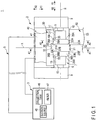
- FIG. 1 shows a removing apparatus (cleaner unit) 1 according to a first embodiment.
- FIG. 2 shows a cross section taken along the line A1-A1 in FIG. 1
- FIG. 3 shows a cross section taken along the line A2-A2 in FIG. 1 .
- the removing apparatus (scraping device) 1 includes a cleaner head 2, a dust collector 3, and a duct 5 connecting the cleaner head 2 and the dust collector 3.
- the cleaner head 2 has a head axis X as the central axis.
- the cleaner head 2 includes an outer cover 6, a rotating unit (brush unit) 7, and a supporting member 9 supporting the rotating unit 7.
- the rotating unit 7 is attached to the supporting member 9 rotatably about a rotation axis R.
- the rotating unit 7 is attached to the supporting member 9 via a shaft 10, and rotates about the rotation axis R together with the shaft 10.
- a storing space 11 is formed inside the outer cover 6.
- the storing space 11 is defined by the outer cover 6 and the supporting member 9.
- the rotating unit 7 is arranged in the storing space 11.
- the outer cover 6 has an opening 12 where the storing space 11 is open to the outside of the cleaner head 2.
- FIG. 1 shows the storing space 11 seen from one side of the second intersecting direction.
- FIGS. 2 and 3 show cross sections perpendicular to or approximately perpendicular to the rotation axis direction.
- the head axis X extends along the first intersecting direction, and the first intersecting direction matches or approximately matches the head axis direction along the head axis X.
- the storing space 11 opens to one side (the side of the X1) of the first intersecting direction (the head axis direction).
- the rotating unit 7 includes the rotation base 13, a rotor (first rotor) 15, and rotors (second rotors) 16A and 16B.
- the rotation base 13 is installed on the outer peripheral surface of the shaft 10.
- the rotor (rotating brush) 15 and the rotors 16A and 16B are arranged on the outer peripheral surface 17 of the rotation base 13.
- the rotor 15 By the rotor 15 being rotationally driven, the rotors 16A and 16B rotate around the rotation axis R together with the rotation base 13, the rotor 15, and the shaft 10.
- the rotors 16A and 16B are arranged next to the rotor 15 in the rotation axis direction along the rotation axis R.
- the rotor 16A is arranged on one side (the side of arrow Y1) of the rotation axis direction with respect to the rotor 15, and the rotor 16B is arranged on the side (the side of arrow Y2) opposite to the rotor 16A with respect to the rotor 15 in the rotation axis direction. Accordingly, the rotor 15 is arranged between the rotors 16A and 16B according to the rotation axis direction.
- FIG. 2 shows a cross section through the rotor (first rotor) 15, and
- FIG. 3 shows a cross section through the rotor (second rotor) 16A.
- a cross section perpendicular to or approximately perpendicular to the rotation axis direction and passing through the rotor (second rotor) 16B is similar to the cross section shown in FIG. 3 .
- each of the rotors 16A and 16B is adjacent to the rotor 15 in the rotation axis direction. In one embodiment, however, each of the rotors 16A and 16B may be arranged slightly away from the rotor 15 in the rotation axis direction. In this case, a minute gap is formed between each of the rotors 16A and 16B and the rotor 15. Even if the rotors 16A and 16B are arranged away from the rotor 15 in the rotation axis direction, the gap distance of each of the rotors 16A and 16B from the rotor 15 is minute; for example, smaller than the size of the rotor 15 in the rotation axis direction.
- the outer diameter of the rotor 15 is larger than the outer diameter of each of the rotors 16A and 16B. Accordingly, a step surface 23A is formed between the outer peripheral surface 21 of the rotor 15 and the outer peripheral surface 22A of the rotor 16A by the rotor 15.
- a step surface 23B is formed between the outer peripheral surface 21 of the rotor 15 and the outer peripheral surface 22B of the rotor 16B by the rotor 15.
- the step surface 23A faces the side of the rotor 16A in the rotation axis direction.
- the step surface 23B faces the side of the rotor 16B in the rotation axis direction, and faces the side opposite to the side which the step surface 23A faces.
- each of the rotors 16A and 16B is larger than the outer diameter of the rotation base 13. Accordingly, a step surface 25A is formed between the outer peripheral surface 22A of the rotor 16A and the outer peripheral surface 17 of the rotation base 13 by the rotor 16A. Accordingly, a step surface 25B is formed between the outer peripheral surface 22B of the rotor 16B and the outer peripheral surface 17 of the rotation base 13 by the rotor 16B.
- the step surface 25A faces the side opposite from the rotor 15 in the rotation axis direction.
- the step surface 25B faces the side opposite from the rotor 15 in the rotation axis direction, and faces the side opposite to the side which the step surface 25A faces.
- the outer peripheral surface 21 of the rotor 15 is formed of a flexible material, and is formed of a material which can remove a sheet including organic fiber such as sheet 53 described below from a base such as base 52 described below.
- the material for forming the outer peripheral surface of the rotor (first rotor) 15 includes a brush, a sponge, a rubber roll, a nonwoven fabric, a fabric, and a paper roll, for example.
- the rotor 15 is a rotating brush, and a plurality of (multiple) brush bristles (first brush bristles) 27 are provided on the outer peripheral surface 21 of the rotor 15.
- Each of the brush bristles 27 is formed of chemical fiber or animal fiber.
- the chemical fiber for forming the brush bristles 27 includes nylon, polypropylene, chloroethene, polyester, acrylic resin, aramid, and a fluorine resin such as Teflon.
- Animal fiber for forming the brush bristles 27 may be horse hair, pig bristles, sheep wool, and deer hair.
- Each of the brush bristles 27 has a wire diameter from 0.1 mm to 0.5 mm and a bristle length of 30 mm or less. Even if a wire diameter and a bristle length of each of the brush bristles 27 are within the above range, it is preferable that each of the brush bristles 27 of the rotor (rotating brush) 15 has a wire diameter larger than 0.2 mm, or that the ratio of the bristle length to the wire diameter is less than 50.
- a plurality of (multiple) brush bristles (second brush bristles) 28A are provided on the outer peripheral surface 22A of the rotor 16A
- a plurality of (multiple) brush bristles (second brush bristles) 28B are provided on the outer peripheral surface 22B of the rotor 16B.
- Each of brush bristles 28A and 28B is preferably formed of the same material as the brush bristles 27, so as to save the trouble and cost in manufacture of the rotating unit 7.
- Each of brush bristles 28A and 28B preferably has the same or approximately the same wire diameter as the wire diameter of each of brush bristles 27, so as to save the trouble and cost in manufacture of the rotating unit 7.
- each of the rotors 16A and 16B may be formed to have the same or approximately the same outer diameter as the outer diameter of the rotor 15.
- each of the outer peripheral surface 22A of the rotor 16A and the outer peripheral surface 22B of the rotor 16B may be formed of one of a sponge, a rubber roll, a nonwoven fabric, a fabric, and a paper roll, for example.
- a plate 30 is formed in the storing space 11 inside the cleaner head 2.
- the plate 30 is formed of metal, for example.
- the plate 30 is provided at a position (angular position) away from the opening 12 around the rotation axis R.
- the plate 30 is provided at a position (angular position) away from the opening 12 around the rotation axis R by 180° or approximately 180°.
- the plate 30 is arranged on the side opposite to the opening 12 with respect to the rotating unit 7 (the rotor 15 and the rotors 16A and 16B) according to the first intersecting direction.
- the plate 30 includes a plate facing surface 31 that faces the outer peripheral surface of the rotating unit 7.
- the plate facing surface 31 faces the outer peripheral surface of the rotating unit 7 at a position away from the opening 12 around the rotation axis R. In one example shown in FIGS. 1 to 3 , the plate facing surface 31 faces the outer peripheral surface of the rotating unit 7 from the side opposite to the opening 12 in the first intersecting direction.
- a groove 32 is formed on the plate facing surface 31 of the plate 30.
- the groove 32 is recessed on the side away from the rotation axis R, namely, the side away from the rotor 15 and the rotors 16A and 16B.
- the groove 32 opens to the side close to the rotation axis R, namely, the side where the rotor 15 and the rotors 16A and 16B are located.
- An opening edge 33 of the groove 32 is formed on the plate facing surface 31.
- the rotor (first rotor) 15 and the rotor (second rotor rotor) 16A and 16B are inserted in the groove 32.
- the portion of the rotating unit 7 other than the rotor 15 and the rotors 16A and 16B is not inserted in the groove 32.
- the rotation base 13 is not inserted in the groove 32.
- the portion of the rotor 15 and the rotors 16A and 16B which projects from the rotation base 13 to the outer peripheral side is inserted in the groove 32.
- the shape of the groove 32 corresponds to the portion of the rotor 15 and the rotors 16A and 16B which projects from the rotation base 13 to the outer peripheral side.
- the groove 32 is formed into a shape corresponding to the rotor 15 and the rotors 16A and 16B.
- the groove 32 has a contact surface 35 that is in contact with the outer peripheral surface 21 of the rotor 15.
- the contact surface 35 is in contact with the outer peripheral surface 21 (the brush bristles 27) of the rotor (first rotor) 15 in the groove 32.
- the outer peripheral surface 21 of the rotor 15 is in contact with the contact surface 35 at a position away from the opening 12 around the rotation axis R.
- the outer peripheral surface 21 (the brush bristles 27) is in contact with the contact surface 35 at a position away from the opening 12 around the rotation axis R by 180° or approximately 180°.
- the groove 32 also has a contact surface (first contact surface) 36A in contact with the outer peripheral surface 22A of the rotor 16A, and a contact surface (first contact surface) 36B in contact with the outer peripheral surface 22B of the rotor 16B.
- the contact surface 36A is in contact with the outer peripheral surface 22A (the brush bristles 28A) of the rotor 16A in the groove 32.
- the contact surface 36B is in contact with the outer peripheral surface 22B (the brush bristles 28B) of the rotor 16B in the groove 32.
- the outer peripheral surface 22A of the rotor 16A is in contact with the contact surface 36A at a position away from the opening 12 around the rotation axis R
- the outer peripheral surface 22B of the rotor 16B is in contact with the contact surface 36B at a position away from the opening 12 around the rotation axis R.
- each of the contact surfaces 36A and 36B is in contact with the corresponding one of the outer peripheral surface 22A of the rotor 16A and the outer peripheral surface 22B of the rotor 16B at a position away from the opening 12 by 180° or approximately 180° around the rotation axis R.
- the contact surface (first contact surface) 36A is arranged on one side relative to the contact surface (second contact surface) 35 in the rotation axis direction, and the contact surface (first contact surface) 36B is arranged on the side opposite to the contact surface 36A with respect to the contact surface (second contact surface) 35 along the rotation axis direction. Accordingly, the contact surface (second contact surface) 35 is provided at a different portion from the contact surfaces (first contact surfaces) 36A and 36B.
- the depth of the groove 32 at the contact surface 35 is larger than the depth of the groove 32 at each of the contact surfaces 36A and 36B.
- a step surface 37A is formed between the contact surface 35 and the contact surface 36A.
- a step surface 37B is formed between the contact surface 35 and the contact surface 36B.
- the step surface 37A is continuously extended from the contact surface 35 to the contact surface 36A, and the step surface 37B is continuously extended from the contact surface 35 to the contact surface 36B.
- the step surface 37A faces the step surface 23A of the rotor 15 from the side where the rotor 16A is located.
- the step surface 37B faces the step surface 23B of the rotor 15 from the side where the rotor 16B is located.
- the rotor 15 is arranged between the step surfaces 37A and 37B in the rotation axis direction.
- the step surface 37A is not in contact with the rotor 15, and there is a gap between the step surface 37A and the step surface 23A of the rotor 15.
- the step surface 37B is not in contact with the rotor 15, and there is a gap between the step surface 37B and the step surface 23B of the rotor 15.
- a groove side surface 38A is continuously extended from the contact surface 36A to the opening edge 33 of the groove 32.
- a groove side surface 38B is continuously extended from the contact surface 36B to the opening edge 33 of the groove 32.
- the groove side surface 38A faces the step surface 25A of the rotor 16A from the side opposite to the rotor 15.
- the groove side surface 38B faces the step surface 25B of the rotor 16B from the side opposite to the rotor 15.
- the rotor 16A is arranged between the groove side surface 38A and the rotor 15 according to the rotation axis direction.
- the rotor 16B is arranged between the groove side surface 38B and the rotor 15 according to the rotation axis direction.
- the groove side surface 38A is not in contact with the rotor 16A, and there is a gap between the groove side surface 38A and the step surface 25A of the rotor 16A.
- the groove side surface 38B is not in contact with the rotor 16B, and there is a gap between the groove side surface 38B and the step surface 25B of the rotor 16B.
- a relay member 40 is connected to the plate 30.
- the relay member 40 is connected to the plate 30 from the side opposite to the rotating unit 7 in the first intersecting direction (the head axis direction).
- a relay space 41 is formed inside the relay member 40.
- the storing space 11 communicates with the relay space 41 via the flow paths 42A, 42B, and 42C.
- the flow paths 42A to 42C are respectively extended along the first intersecting direction (the direction indicated by arrows X1 and X2).
- the flow path 42A is formed through the inside of the plate 30.
- the flow path 42B is located on one side of the second intersecting direction (the direction indicated by arrows Y1 and Y2) relative to the flow path 42A.
- the flow path 42C is located on the side opposite to the flow path 42B with respect to the flow path 42A in the second intersecting direction.
- Each of the flow paths 42A to 42C has a dimension (width) of 2 mm or more in the second intersecting direction at any portion.
- Each of the flow paths 42A to 42C has a dimension (width) of 2 mm or more in the rotation axis direction (the direction indicated by arrows R1 and R2) at any portion.
- one end of the duct 5 is connected to the relay member 40 of the cleaner head 2.
- the inside of the duct 5 communicates with the relay space 41.
- the other end of the duct 5 is connected to the dust collector 3.
- the dust collector 3 includes a suction source 45 including a suction pump, a collection tank 46, and a filter 47.
- Suction force acts in the cleaner head 2 by actuating the suction source 45.
- suction force from the opening 12 to the storing space 11 acts and suction force from the storing space 11 to the suction source 45 acts in the removing apparatus 1 that includes the cleaner head 2.
- the width and the cross-sectional area of the suction path from the opening 12 to the dust collector 3 are the smallest in each of the flow paths 42A to 42C. Accordingly, the width of the suction path from the opening 12 to the dust collector 3 is 2 mm or more at any portion.
- a conveying roller 51 is provided in the system using the removing apparatus 1, a conveying roller 51 is provided.
- the conveying roller 51 forms a part of a conveying apparatus, and the processing target 50 by the removing apparatus 1 is conveyed by the conveying apparatus.
- a sheet 53 including organic fiber is formed on the surface of the base 52.
- the sheet 53 is formed on the surface of the base 52 by, for example, an electrospinning method using a spinning head (not shown).
- a solution in which an organic material dissolves in a solvent is filled inside the spinning head.
- a voltage (high voltage) is applied between the spinning head and the base 52, which leads to ejection of the solution of the organic material from the nozzle of the spinning head to the surface of the base 52.
- a sheet (layer) 53 including organic fiber is formed on the surface of the base 52.
- the sheet 53 is an insulating layer having an electrical insulation property.
- polyolefin As an organic material to be filled in the spinning head, one or more of polyolefin, polyether, polyimide, polyketone, polysulfone, cellulose, polyvinyl alcohol (PVA), polyamide, polyamide-imide, and polyvinylidene fluoride (PVdf) are selected, for example.
- Polyolefin includes polypropylene (PP) and polyethylene (PE), for example.
- PP polypropylene
- PE polyethylene
- the organic material is dissolved in a concentration from 5 % by mass to 60 % by mass in a solvent.
- a given solvent such as dimethylacetamide (DMAc), dimethylsulfoxide (DMSO), N,N-dimethylformamide (DMF), N-methylpyrrolidone (NMP), water, and alcohol, for example, is used.
- DMAc dimethylacetamide
- DMSO dimethylsulfoxide
- DMF N,N-dimethylformamide
- NMP N-methylpyrrolidone
- the voltage between the spinning head and the base 52 is appropriately determined in correspondence with the kind of the solvent and the solute, the boiling point and the vapor pressure curve of the solvent, the solution concentration, the temperature, the shape of the nozzle of the spinning head, and the distance between the base 52 and the nozzle of the spinning head, for example, and is appropriately determined within, for example, 1 kV to 100 kV.
- the supply speed of the solution of the organic material is appropriately determined in correspondence with the solution concentration, the solution viscosity, the temperature, the pressure, the applied voltage, and the shape of the nozzle of the spinning head, for example.
- Formation of the sheet 53 including organic fiber namely, spinning of organic fiber on the surface of the base 52 may be performed by a method other than electrospinning.
- the sheet 53 including organic fiber may be formed on the surface of the base 52 by one of the ink-jet method, the jet-dispenser method, and the splay-application method, instead of the electrospinning method.
- the processing target 50 where the sheet 53 including organic fiber is formed on the base 52 by spinning of the electrospinning method, for example, is conveyed to the removing apparatus (scraping device) 1 by the conveying apparatus including the conveying roller 51. Then, the processing by the removing apparatus 1 is performed.
- the outer peripheral surface 21 (brush bristles 27) of the rotor 15 is brought into contact with the sheet 53, which includes organic fiber and is formed on the surface of the base 52.
- the rotor (first rotor) 15 comes into contact with the sheet 53 at the opening 12 of the storing space 11.
- the rotating unit 7 including the rotor (first rotor) 15 and the rotors (second rotor) 16A and 16B is rotated about the rotation axis R so as to rotationally drive the rotor 15.
- the organic fiber on the sheet 53 is removed (scraped off) by the rotational drive of the rotor 15.
- organic fiber is removed from a part of the sheet 53 by the rotor 15. Accordingly, in the processing target 50 even after the processing by the removing apparatus 1 is completed, the sheet 53 including organic fiber is still formed on a portion of the surface of the base 52 which is not subjected to the removal by the rotor 15.
- the sheet 53 removed from the base 52 may be caught on the outer peripheral surface 21 (brush bristles 27) of the rotor 15.
- the contact surface (second contact surface) 35 is in contact with the outer peripheral surface 21 (brush bristles 27) of the rotor 15 at a position away from the opening 12 around the rotation axis R, namely, a position away from the base 52 and the sheet 53 around the rotation axis R.
- a part of or all of the organic fiber (sheet 53) removed from the base 52 and caught on the outer peripheral surface 21 (brush bristles 27) of the rotor 15 is removed through the contact between the contact surface 35 and the outer peripheral surface 21 while the rotor 15 is rotating.
- the organic fiber (sheet 53) removed from the base 52 and the organic fiber (sheet 53) removed from the rotor 15 may be accumulated in the gap between the step surface 23A of the rotor (first rotor) 15 and the step surface 37A of the groove 32.
- the organic fiber removed (scraped off) from the sheet 53 may be caught directly on the outer peripheral surface 22A of the rotor 16A, and the organic fiber accumulated in the gap between the step surfaces 23A and 37A may be caught on the outer peripheral surface 22A of the rotor 16A.
- the organic fiber (sheet 53) removed from the base 52 and the organic fiber (sheet 53) removed from the rotor 15 may be accumulated in the gap between the step surface 23B of the rotor 15 and the step surface 37B of the groove 32.
- the organic fiber removed from the sheet 53 may be caught directly on the outer peripheral surface 22B of the rotor 16B, and the organic fiber accumulated in the gap between the step surfaces 23B and 37B may be caught on the outer peripheral surface 22B of the rot
- the contact surface (first contact surface) 36A is in contact with the outer peripheral surface 22A of the rotor 16A at a position away from the opening 12 around the rotation axis R, namely, a position away from the base 52 and the sheet 53 around the rotation axis R.
- a part of or all of the organic fiber (sheet 53) removed from the base 52 and caught on the outer peripheral surface 22A of the rotor 16A is removed through the contact between the contact surface 36A and the outer peripheral surface 22A of the rotor 16A while the rotor 16A is rotating together with the rotor 15.
- the contact surface (first contact surface) 36B is in contact with the outer peripheral surface 22B of the rotor 16B at a position away from the opening 12 around the rotation axis R, namely, a position away from the base 52 and the sheet 53 around the rotation axis R.
- a part of or all of the organic fiber (sheet 53) removed from the base 52 and caught on the outer peripheral surface 22B of the rotor 16B is removed through the contact between the contact surface 36B and the outer peripheral surface 22B of the rotor 16B while the rotor 16B is rotating together with the rotor 15.
- the outer diameter of the rotor 15 is larger than the outer diameter of each of the rotors 16A and 16B, as described above. Furthermore, the step surface 23A is formed between the outer peripheral surface 21 of the rotor 15 and the outer peripheral surface 22A of the rotor 16A, and the step surface 23B is formed between the outer peripheral surface 21 of the rotor 15 and the outer peripheral surface 22B of the rotor 16B. Because of such a configuration, the rotor 16A rotates together with the rotor (rotating brush) 15 without being in contact with the sheet 53 of the processing target 50. Similarly, the rotor 16B rotates together with the rotor 15 without being in contact with the sheet 53 of the processing target 50. This effectively prevents each of the rotors 16A and 16B from coming into contact with the sheet 53.
- the organic fiber caught thereon is removed as described above. Therefore, the organic fiber is prevented from being caught on the outer peripheral surface 22A of the rotor 16A and the outer peripheral surface 22B of the rotor 16B in large amounts, and the caught organic fiber is prevented from interfering with the sheet 53. This effectively prevents the sheet 53 from being removed by the organic fiber caught on the outer peripheral surface 22A of the rotor 16A. Similarly, the sheet 53 is effectively prevented from being removed by the organic fiber caught on the outer peripheral surface 22B of the rotor 16B.
- the sheet 53 is prevented from being removed by the organic fiber caught on each of the rotors 16A and 16B.
- the organic fiber is appropriately removed only from a portion of the sheet 53 of the processing target 50 with which the outer peripheral surface 21 (brush bristles 27) of the rotor 15 comes into contact, namely, only from a desired portion of the sheet 53.
- a gap is provided between the step surface 23A of the rotor 15 and the step surface 37A of the groove 32.
- Another gap is provided between the step surface 23B of the rotor 15 and the step surface 37B of the groove 32.
- the plate 30 formed of metal, for example is separate from the rotor 15 in the rotation axis direction. Accordingly, the plate 30 is prevented from coming into contact with the brush bristles 27 of the rotor 15 from the rotation axis direction. Increase in the life of the rotor 15 is achieved by the plate 30 not being in contact with the rotor 15 from the rotation axis direction while the rotor 15 is rotating.
- the dust collector 3 is driven.
- the organic fiber removed by the rotor 15 is sucked from the opening 12 of the cleaner head 2 to the inside of the storing space 11.
- the organic fiber sucked into the storing space 11 is sucked and collected in the collection tank 46 of the dust collector 3.
- the organic fiber removed from the outer peripheral surface 21 (brush bristles 27) of the rotor 15 and the organic fiber removed from each of the outer peripheral surface 22A of the rotor 16A and the outer peripheral surface 22B of the rotor 16B are also sucked and collected in the collection tank 46 of the dust collector 3.
- the organic fiber moves from the storing space 11 to the dust collector 3 through one of the flow paths 42A to 42C, the relay space 41, and the inside of the duct 5 in this order.
- the filter 47 prevents the organic fiber from flowing into the suction source 45.
- the width of the suction path from the opening 12 to the dust collector 3 is 2 mm or more even in the narrowest flow paths 42A to 42C.
- the removing apparatus 1 is used for forming an electrode group of a battery such as a nonaqueous electrolyte secondary battery and an alkaline secondary battery, and for forming a separator-integrated electrode in which a positive electrode and/or a negative electrode is integrated with a separator, for example.
- FIG. 4 shows one example of an electrode group 100 having a separator-integrated electrode formed by using the removing apparatus 1.
- the electrode group 100 is provided in a battery such as a sealed nonaqueous electrolyte secondary battery, for example.
- the electrode group 100 is stored inside an exterior covering member. Inside the exterior covering member, the electrode group 100 is impregnated with an electrolytic solution (not shown).
- an exterior covering member either a bag-shape container made of a laminating film or a metal container may be used.
- the shape of the exterior covering member may be a flat shape, a rectangular shape, a cylindrical shape, a coin-like shape, a button-like shape, a sheet-like shape, and a laminated shape, for example.
- a laminating film a multi-layer film may be used, for example, and the multi-layer film may include a plurality of resin layers and a metal layer arranged between the resin layers.
- metal layer for example, aluminum foil or aluminum alloy foil may be used, and as a resin layer, for example, a polymer material such as polypropylene (PP), polyethylene (PE), nylon, and polyethylene terephthalate (PET) may be used.
- PP polypropylene
- PE polyethylene
- PET polyethylene terephthalate
- the metal container is formed of at least one kind of metal selected from a group including, for example, aluminum, zinc, titanium, and iron, or is formed of an alloy of these metals.
- the electrode group 100 includes a positive electrode 101 and a negative electrode 102.
- FIG. 5 shows the laminated state of the positive electrode 101 and the negative electrode 102 in the electrode group 100.
- a separator 103 is provided in addition to the positive electrode 101 and the negative electrode 102, and the separator 103 is formed integrally with the negative electrode 102.
- the removing apparatus 1 is used for forming a separator-integrated electrode in which the negative electrode 102 is integrated with the separator 103.
- the separator 103 is attached closely to and fixed to the surface of the negative electrode 102, and the separator 103 electrically insulates the positive electrode 101 from the negative electrode 102.
- the separator 103 is formed on the surface of the negative electrode 102 by, for example, the aforementioned electrospinning method.
- the separator 103 is formed of the aforementioned organic material filled inside the spinning head (not shown). Accordingly, if the separator 103 is formed integrally with the negative electrode 102 by, for example, the electrospinning method, the negative electrode 102 is the base 52, and the separator 103 is the sheet 53 which includes the organic fiber and is formed on the surface of the negative electrode 102.
- the description below will describe a case where the separator 103 is formed on the negative electrode 102; however, the same configuration applies to a case where the separator 103 is formed on the surface of the positive electrode 101 by, for example, the electrospinning method.
- the positive electrode 101 includes a positive electrode current collecting foil 111 as a positive electrode current collector, and a positive electrode active material-containing layer 112 supported on the surface of the positive electrode current collecting foil 111.
- the positive electrode current collecting foil 111 is aluminum foil or aluminum alloy foil, for example, and has a thickness of about 10 ⁇ m to 20 ⁇ m.
- Slurry including a positive electrode active material, a binding agent, and an electro-conductive agent is applied to the positive electrode current collecting foil 111.
- the positive electrode active material-containing layer 112 is formed by applying the slurry to the positive electrode current collecting foil 111.
- the positive electrode active material may be an oxide, a sulfide, and a polymer, for example, which can occlude and release lithium.
- the positive electrode active material it is preferable to use a lithium-manganese composite oxide, a lithium-nickel composite oxide, a lithium-cobalt composite oxide, and lithium iron phosphate, for example, since a high positive electrode potential can be obtained.
- the negative electrode 102 includes a negative electrode current collecting foil 121 as a negative electrode current collector, and a negative electrode active material-containing layer 122 supported on the surface of the positive electrode current collecting foil 121.
- the negative electrode current collecting foil 121 is aluminum foil or aluminum alloy foil, for example, and has a thickness of about 10 ⁇ m to 20 ⁇ m.
- a slurry including a negative electrode active material, a binding agent, and an electro-conductive agent is applied to the negative electrode current collecting foil 121.
- the negative electrode active material-containing layer 122 is formed by applying the slurry to the negative electrode current collecting foil 121.
- the negative electrode active material may be a metal oxide, metal sulfide, metal nitride, and alloy, for example, which can occlude and release lithium.
- the negative electrode active material is preferably a material which occludes and releases lithium ions at a potential of 0.4 V or more with respect to a metal lithium potential.
- the reaction of aluminum or an aluminum alloy with lithium is suppressed by using the negative electrode active material having a lithium ion occlusion-and-release potential as described above, which allows usage of aluminum and an aluminum alloy for a structural member related to the negative electrode current collecting foil 121 and the negative electrode 102.
- the negative electrode may be a titanium oxide, a lithium titanium composite oxide such as lithium titanate, a tungsten oxide, an amorphous tin oxide, a tin silicon oxide, and a silicon oxide, for example. It is especially preferable to use a lithium titanium composite oxide as the negative electrode active material.
- the aluminum alloy used for the positive electrode and the negative electrode preferably includes one or more kinds of elements selected from Mg, Ti, Zn, Mn, Fe, Cu and Si.
- the purity of aluminum and aluminum alloy may be set to 98 % by weight or more, and is preferably 99.99 % by weight or more. Pure aluminum having a purity of 100 % can be used as a material for the positive electrode current collector and/or the negative electrode current collector. It is preferable to set the contained amount of transition metal such as nickel and chrome in aluminum and aluminum alloy to 100 ppm by weight or less (including 0 ppm by weight).
- the positive electrode 101, the negative electrode 102, and the separator 103 are wound around a winding axis B with the separator 103 being arranged between the positive electrode 101 and the negative electrode 102.
- the positive electrode 101 and the negative electrode 102 are alternately laminated with the separator 103 being interposed therebetween.
- the positive electrode current collecting foil 111 includes a pair of long side edges 113A and 113B, and a positive electrode current collecting tab 115 is formed in the positive electrode current collecting foil 111 by one (113A) of the long side edges 113A and 113B and its near portion.
- the positive electrode current collecting tab 115 is formed over a predetermined distance from the long side edge 113A in the direction along the winding axis B, and the positive electrode active material-containing layer 112 is not supported on the positive electrode current collecting tab 115.
- the negative electrode current collecting foil 121 has a pair of long side edges 123A and 123B, and a negative electrode current collecting tab 125 is formed in the negative electrode current collecting foil 121 by one (123A) of the long side edges 123A and 123B and its near portion.
- the negative electrode current collecting tab 125 is formed over a predetermined distance from the long side edge 123A in the direction along the winding axis B, and the negative electrode active material-containing layer 122 is not supported on the negative electrode current collecting tab 125.
- the positive electrode 101 and the negative electrode 102 are arranged to be shifted with respect to each other in a direction along the winding axis B. Accordingly, the positive electrode current collecting tab 115 not supporting the positive electrode active material-containing layer 112 projects to one side of the direction along the winding axis B with respect to the negative electrode 102 and the separator 103.
- the negative electrode current collecting tab 125 not supporting the negative electrode active material-containing layer 122 projects to the side opposite to the side to which the positive electrode current collecting tab 115 projects, with respect to the positive electrode 101 and the separator 103 in the direction along the winding axis B.
- the positive electrode current collecting tab 115 is bundled by bonding the surfaces of the positive electrode current collecting foil 111 in the positive electrode current collecting tab 115 by ultrasonic welding, for example. Then, the positive electrode current collecting tab 115 is electrically connected to the positive electrode terminal of the battery via one or more positive electrode leads.
- the negative electrode current collecting tab 125 is bundled by bonding the surfaces of the negative electrode current collecting foil 121 in the negative electrode current collecting tab 125 by ultrasonic welding, for example. Then, the negative electrode current collecting tab 125 is electrically connected to the negative electrode terminal of the battery via one or more negative electrode leads.
- the positive electrode current collecting tab 115, the negative electrode current collecting tab 125, the positive electrode lead, the negative electrode lead, the positive electrode terminal, and the negative electrode terminal are insulated from the exterior covering member.
- the electrode terminals such as the positive electrode terminal and the negative electrode terminal are provided to be exposed to the outside of the exterior covering member.
- the separator 103 is formed on the negative electrode 102, for example, by the electrospinning method, etc. before winding the positive electrode 101 and the negative electrode 102.
- a slurry including the negative electrode active material is applied to the negative electrode current collecting foil 121 before forming the separator 103 by the electrospinning method, for example.
- the slurry including the negative electrode active material is not applied to one (123A) of the long side edges 123A and 123B and its near portion, namely, a portion in which the negative electrode current collecting tab 125 is formed.
- the negative electrode active material-containing layer 122 is formed on a portion of the surface of the negative electrode current collecting foil 121 other than the portion in which the negative electrode current collecting tab 125 is formed.
- FIG. 6 shows a state of the negative electrode 102 after forming the sheet 53 (separator 103) including the organic fiber by the electrospinning method, for example, and before performing the processing by the removing apparatus (scraping device) 1.
- the sheet 53 including organic fiber is formed on the entire surface of the negative electrode 102.
- the sheet 53 covers both of the portion of the negative electrode current collecting foil 121 supporting the negative electrode active material-containing layer 122 and its adjacent (continuing) portion not supporting the negative electrode active material-containing layer 122. Accordingly, until the processing of the removing apparatus 1, the sheet 53 covers the portion forming the negative electrode current collecting tab 125.
- FIG. 7 shows a state of the negative electrode 102 right after completing the processing by the removing apparatus 1.
- the organic fiber is scraped off from a part of the portion forming the negative electrode current collecting tab 125.
- the organic fiber is scraped off from the negative electrode current collecting foil 121 over a predetermined length L1 from the long side edge 123A of the negative electrode current collecting foil 121 on the side of the negative electrode current collecting tab 125.
- the predetermined length L1 is smaller than a length L2 from the long side edge 123A of the negative electrode current collecting foil 121 on the side of the negative electrode current collecting tab 125 to the end of the negative electrode active material-containing layer 122 on the side of the negative electrode current collecting tab 125. Accordingly, the sheet 53 is not scraped off from the portion that carries the negative electrode active material-containing layer 122. Therefore, even after the processing by the removing apparatus 1, the portion that supports the negative electrode active material-containing layer 122 is covered with the sheet 53 (separator 103). Furthermore, the organic fiber is not scraped off from the entire part of the negative electrode current collecting tab 125 that does not carry the negative electrode active material-containing layer 122. Thus, even after completing the processing by the removing apparatus 1, the sheet 53 including the organic fiber covers the part of the negative electrode current collecting tab 125 which is near the negative electrode active material-containing layer 122.
- the sheet 53 is scraped off from a part of the negative electrode current collecting tab 125 of the negative electrode 102.
- the sheet 53 is prevented from being removed by the organic fiber caught on each of the rotors 16A and 16B. Accordingly, in the negative electrode 102, the sheet 53 is effectively prevented from being removed from a portion which supports the negative electrode active material-containing layer 122.
- the organic fiber is appropriately scraped off from only a portion of the negative electrode current collecting tab 125 which does not support the negative electrode active material-containing layer 122 in a separator-integrated electrode where the negative electrode 102 is integrated with the separator 103.
- organic fiber is scraped off from a part of the sheet 53 in the processing target 50 by using a cleaner head 2 and a removing apparatus 1 similar to those in the first embodiment.
- a base 52 similar to the aforementioned negative electrode 102 is used as the processing target 50, and the sheet 53 including the organic fiber is formed by the electrospinning method.
- Polyimide is used as an organic material for forming the organic fiber
- NMP N-methylpyrrolidone
- the voltage between the spinning head and the base 52 is set to 30kV.
- Aluminum alloy foil having a thickness of 15 ⁇ m is used as the negative electrode current collecting foil 121 for forming the base 52.
- Lithium titanate having a spinel structure is used as the negative electrode active material.
- the organic fiber is scraped off from the sheet 53 continuously over 2000 m.
- the sheet 53 is effectively prevented from being scraped off by the organic fiber caught on the rotors 16A and 16B in the removing apparatus 1 of the present embodiment. Accordingly, it is proved that the organic fiber is appropriately scraped off from a portion of the sheet 53 of the processing target 50 which is in contact with the outer peripheral surface 21 (brush bristles 27) of the rotor 15, namely, a desired portion.
- the step surface 23A is not formed between the outer peripheral surface 21 of the rotor (first rotor) 15 and the outer peripheral surface 22A of the rotor (second rotor) 16A
- the step surface 23B is not formed between the outer peripheral surface 21 of the rotor 15 and the outer peripheral surface 22B of the rotor (second rotor) 16B
- a step surface 25A is formed between the outer peripheral surface 22A of the rotor 16A and the outer peripheral surface 17 of the rotation base 13 by the rotor 16A
- a step surface 25B is formed between the outer peripheral surface 22B of the rotor 16B and the outer peripheral surface 17 of the rotation base 13 by the rotor 16B.
- the outer peripheral surface 22A of the rotor 16A is extended from the outer peripheral surface 21 of the rotor 15 to the step surface 25A.
- the outer peripheral surface 22B of the rotor 16B is extended from the outer peripheral surface 21 of the rotor 15 to the step surface 25B.
- the outer diameter of the rotor 16A is smaller as a position is further away from the rotor 15 in the rotation axis direction along the rotation axis R. Accordingly, the outer peripheral surface 22A of the rotor 16A is formed into a tapered surface of which distance from the rotation axis R is smaller as a position is further away from the rotor 15 in the rotation axis direction. Similarly, the outer diameter of the rotor 16B is smaller as a position is further away from the rotor 15 in the rotation axis direction along the rotation axis R.
- the outer peripheral surface 22B of the rotor 16B is formed into a tapered surface of which distance from the rotation axis R is smaller as a position is further away from the rotor 15 in the rotation axis direction.
- the rotor (second rotor) 16A rotates together with the rotor (first rotor) 15 without being in contact with the sheet 53 of the processing target 50.
- the rotor (second rotor) 16B rotates together with the rotor 15 without being in contact with the sheet 53 of the processing target 50. Accordingly, also in the present modification, each of the rotors 16A and 16B is effectively prevented from coming into contact with the sheet 53.
- a plate 30 is provided at a position (angle position) away from the opening 12 (sheet 53) around the rotation axis R.
- a groove 32 is formed on a plate facing surface 31 of the plate 30.
- a groove 32 has an opening edge 33, and the aforementioned contact surface (second contact surface) 35, the contact surfaces (first contact surface) 36A and 36B, and the groove side surfaces 38A and 38B.
- the groove side surface 38A is not in contact with the rotor 16A, and there is a gap between the groove side surface 38A and the step surface 25A of the rotor 16A.
- the groove side surface 38B is not in contact with the rotor 16B, and there is a gap between the groove side surface 38B and the step surface 25B of the rotor 16B.
- a step surface 37A is not formed between the contact surface 35 and the contact surface 36A, and a step surface 37B is not formed between the contact surface 35 and the contact surface 36B.
- the contact surface 36A is continuously extended from the contact surface 35 to the groove side surface 38A.
- the contact surface 36B is continuously extended from the contact surface 35 to the groove side surface 38B.
- the depth of the groove 32 is smaller as a portion of the contact surface 36A is further away from the contact surface 35 in the rotation axis direction along the rotation axis R. Accordingly, the contact surface 36A is formed into an inclined surface in which a distance from the opening of the groove 32 is smaller as a position is further away from the rotor 15 in the rotation axis direction. Similarly, the depth of the groove 32 is smaller as a portion of the contact surface 36B is further away from the contact surface 35 in the rotation axis direction along the rotation axis R. Accordingly, the contact surface 36B is formed into an inclined surface in which a distance from the opening of the groove 32 is smaller as a position is further away from the rotor 15 in the rotation axis direction.
- the contact surface 35 is in contact with the outer peripheral surface 21 (brush bristles 27) of the rotor 15 at a position away from the opening 12 (sheet 53) around the rotation axis R.
- the contact surface 35 is in contact with the outer peripheral surface 21 (brush bristles 27) of the rotor 15 at a position away from the opening 12 (sheet 53) around the rotation axis R.
- the contact surface 36A is in contact with the outer peripheral surface 22A of the rotor 16A at a position away from the opening 12 (sheet 53) around the rotation axis R.
- a part of or all of the organic fiber caught on the outer peripheral surface 22A of the rotor 16A is removed through the contact between the contact surface 36A and the outer peripheral surface 22A of the rotor 16A while the rotor 16A is rotating together with the rotor 15.
- the contact surface 36B is in contact with the outer peripheral surface 22B of the rotor 16B at a position away from the opening 12 (sheet 53) around the rotation axis R.
- the organic fiber caught on each of the outer peripheral surface 22A of the rotor 16A and the outer peripheral surface 22B of the rotor 16B is removed. Therefore, the organic fiber is prevented from being caught on the outer peripheral surface 22A of the rotor 16A and the outer peripheral surface 22B of the rotor 16B in large amounts, and the caught organic fiber is prevented from interfering with the sheet 53.
- the sheet 53 is prevented from being removed by the organic fiber caught on each of the rotors 16A and 16B. As a result, the organic fiber is removed only from a portion of the sheet 53 of the processing target 50 with which the outer peripheral surface 21 (brush bristles 27) of the rotor 15 comes into contact, namely, only from a desired portion of the sheet 53.
- a second rotor is arranged next to a first rotor in a direction along the rotation axis of the first rotor, and the second rotor rotates together with the first rotor without being in contact with a sheet.
- a contact surface is in contact with the outer peripheral surface of the second rotor at a position away from the sheet around the rotation axis.
Landscapes
- Engineering & Computer Science (AREA)
- Manufacturing & Machinery (AREA)
- Chemical & Material Sciences (AREA)
- Chemical Kinetics & Catalysis (AREA)
- Electrochemistry (AREA)
- General Chemical & Material Sciences (AREA)
- Nozzles For Electric Vacuum Cleaners (AREA)
- Cell Separators (AREA)
- Battery Electrode And Active Subsutance (AREA)
- Cleaning In General (AREA)
- Cleaning Implements For Floors, Carpets, Furniture, Walls, And The Like (AREA)
Abstract
According to one embodiment, a cleaner head (2) includes a first rotor (15), a second rotor (16A,16B), and a contact surface (36A, 36B). The first rotor (15) can be rotationally driven in a state where an outer peripheral surface (21) of the first rotor (15) is in contact with a sheet (53) that includes organic fiber and is formed on a base (52), and can remove a part of the sheet (53) from the base (52). The second rotor (16A, 16B) is arranged next to the first rotor (15) in a direction along a rotation axis (R) of the first rotor (15), and is rotated together with the first rotor (15) in a state where the second rotor (16A,16B) is not in contact with the sheet (53). The contact surface (36A,36B) is in contact with an outer peripheral surface (22A,22B) of the second rotor (16A,16B) at a position away from the sheet (53) around the rotation axis (R).
Description
- Embodiments described herein relate to a cleaner head, a removing apparatus, and a removing method.
- Electrode groups used for a secondary battery, for example, include an electrode group where a separator configured to insulate a positive electrode from a negative electrode is formed integrally with the positive electrode and/or the negative electrode. When manufacturing this electrode group, a sheet including organic fiber is formed on the surface of the electrode (the positive electrode and/or the negative electrode), by an electrospinning method, for example. The sheet including organic fiber is formed as a separator between the positive electrode and the negative electrode. In a case of forming a separator integrally with either one of the electrodes by the electrospinning method as described above, it is necessary to remove organic fiber from a portion of a current collector which does not support an active material, in other words, a portion where a current collecting tab is formed, after the formation of the sheet including organic fiber on the entire surface of the electrode by the electrospinning method. In this case, for example, a removing apparatus that includes a cleaner head is used. The organic fiber is removed from a part of the sheet by rotationally driving a rotating brush (rotor) in a state where brush bristles of the rotating brush mounted on the cleaner head are in contact with the sheet.
- In the case of removing the organic fiber by the rotating brush (rotor) as described above, it is required that the organic fiber is appropriately removed only from a portion where the current collecting tab is formed, and that the organic fiber is not removed from a portion of the current collector which supports an active material. In other words, in a sheet formed on an electrode, it is required that the sheet (organic fiber) is appropriately removed only from a desired portion.
-
-
FIG. 1 is a schematic diagram showing a configuration of a removing apparatus according to a first embodiment, -
FIG. 2 is a cross-sectional view schematically showing a cross section taken along the line A1-A1 inFIG. 1 , -
FIG. 3 is a cross-sectional view schematically showing a cross section taken along the line A2-A2 inFIG. 1 , -
FIG. 4 is a schematic diagram showing an example of an electrode group that includes a separator-integrated electrode formed by using the removing apparatus according to the first embodiment, -
FIG. 5 is a cross-sectional view schematically showing a laminated state of positive electrodes and negative electrodes in the electrode group ofFIG. 4 , -
FIG. 6 is a cross-sectional view schematically showing the state of a negative electrode during formation of the electrode group ofFIG. 4 after forming a sheet of organic fiber and before performing processing by the removing apparatus, -
FIG. 7 is a cross-sectional view schematically showing a state of the negative electrode during formation of the electrode group ofFIG. 4 right after completing the processing by the removing apparatus, and -
FIG. 8 is a schematic diagram showing a constitution of a cleaner head of a removing apparatus according to a modification of the first embodiment. - The problem to be solved by the embodiments is to provide a cleaner head to remove a sheet (organic fiber) formed on a base only from a desired portion of the base, a removing apparatus that includes the cleaner head, and a removing method using the cleaner head.
- According to an embodiment, a cleaner head that includes a first rotor, a second rotor, and a contact surface is provided. The first rotor can be rotationally driven in a state where the outer peripheral surface of the first rotor is in contact with a sheet that includes organic fiber and is formed on the surface of a base. It is possible to remove a part of the sheet from the base by rotationally driving the first rotor in a state where the outer peripheral surface of the first rotor is in contact with the sheet. The second rotor is arranged next to the first rotor in the direction along the rotation axis of the first rotor. The second rotor is rotated together with the first rotor by the rotational drive of the first rotor in a state where the second rotor is not in contact with the sheet. The contact surface is in contact with the outer peripheral surface of the second rotor at a position away from the base and the sheet around the rotation axis. A part of or all of the sheet removed from the base and caught on the outer peripheral surface of the second rotor can be removed through the contact between the contact surface and the outer peripheral surface of the second rotor while the second rotor is rotating.
- According to the embodiment, a removing apparatus that includes the aforementioned cleaner head and a dust collector is provided. The dust collector can collect the sheet removed from the base by the first rotor by making suction power act in the cleaner head.
- According to the embodiment, a removing method of removing a part of a sheet that includes organic fiber and is formed on a base is provided. In the removing method, the part of the sheet is removed from the base by rotationally driving the first rotor while the outer peripheral surface of the first rotor is in contact with the sheet. In the removing method, the second rotor, which is arranged next to the first rotor in the direction along the rotation axis of the first rotor, is rotated together with the first rotor by the rotational drive of the first rotor in a state where the second rotor is not in contact with the sheet. In the removing method, the contact surface is in contact with the outer peripheral surface of the second rotor at a position away from the base and the sheet around the rotation axis while the second rotor is rotating. As a result, a part of or all of the sheet removed from the base and caught on the outer peripheral surface of the second rotor is removed.
- Hereinafter, the embodiment will be described with reference to
FIGS. 1 to 8 . -
FIG. 1 shows a removing apparatus (cleaner unit) 1 according to a first embodiment.FIG. 2 shows a cross section taken along the line A1-A1 inFIG. 1 , andFIG. 3 shows a cross section taken along the line A2-A2 inFIG. 1 . As shown inFIGS. 1 to 3 , the removing apparatus (scraping device) 1 includes acleaner head 2, a dust collector 3, and aduct 5 connecting thecleaner head 2 and the dust collector 3. Thecleaner head 2 has a head axis X as the central axis. Thecleaner head 2 includes anouter cover 6, a rotating unit (brush unit) 7, and a supportingmember 9 supporting the rotatingunit 7. The rotatingunit 7 is attached to the supportingmember 9 rotatably about a rotation axis R. The rotatingunit 7 is attached to the supportingmember 9 via ashaft 10, and rotates about the rotation axis R together with theshaft 10. - In the
cleaner head 2, astoring space 11 is formed inside theouter cover 6. Thestoring space 11 is defined by theouter cover 6 and the supportingmember 9. The rotatingunit 7 is arranged in thestoring space 11. Theouter cover 6 has anopening 12 where thestoring space 11 is open to the outside of thecleaner head 2. Relative to thecleaner head 2, the following description will specify a rotation axis direction along the rotation axis R (the direction indicated by arrows R1 and R2), a first intersecting direction (the direction indicated by arrows X1 and X2) intersecting with (perpendicular to or approximately perpendicular to) the rotation axis direction, and a second intersecting direction (the direction indicated by arrows Y1 and Y2) intersecting with (perpendicular to or approximately perpendicular to) both the rotation axis direction and the first intersecting direction.FIG. 1 shows thestoring space 11 seen from one side of the second intersecting direction.FIGS. 2 and 3 show cross sections perpendicular to or approximately perpendicular to the rotation axis direction. The head axis X extends along the first intersecting direction, and the first intersecting direction matches or approximately matches the head axis direction along the head axis X. At the opening 12, thestoring space 11 opens to one side (the side of the X1) of the first intersecting direction (the head axis direction). - The
rotating unit 7 includes therotation base 13, a rotor (first rotor) 15, and rotors (second rotors) 16A and 16B. Therotation base 13 is installed on the outer peripheral surface of theshaft 10. The rotor (rotating brush) 15 and therotors peripheral surface 17 of therotation base 13. By therotor 15 being rotationally driven, therotors rotation base 13, therotor 15, and theshaft 10. Therotors rotor 15 in the rotation axis direction along the rotation axis R. Therotor 16A is arranged on one side (the side of arrow Y1) of the rotation axis direction with respect to therotor 15, and therotor 16B is arranged on the side (the side of arrow Y2) opposite to therotor 16A with respect to therotor 15 in the rotation axis direction. Accordingly, therotor 15 is arranged between therotors FIG. 2 shows a cross section through the rotor (first rotor) 15, andFIG. 3 shows a cross section through the rotor (second rotor) 16A. A cross section perpendicular to or approximately perpendicular to the rotation axis direction and passing through the rotor (second rotor) 16B is similar to the cross section shown inFIG. 3 . - In the present embodiment, each of the
rotors rotor 15 in the rotation axis direction. In one embodiment, however, each of therotors rotor 15 in the rotation axis direction. In this case, a minute gap is formed between each of therotors rotor 15. Even if therotors rotor 15 in the rotation axis direction, the gap distance of each of therotors rotor 15 is minute; for example, smaller than the size of therotor 15 in the rotation axis direction. - The outer diameter of the
rotor 15 is larger than the outer diameter of each of therotors step surface 23A is formed between the outerperipheral surface 21 of therotor 15 and the outerperipheral surface 22A of therotor 16A by therotor 15. Astep surface 23B is formed between the outerperipheral surface 21 of therotor 15 and the outerperipheral surface 22B of therotor 16B by therotor 15. On therotor 15, thestep surface 23A faces the side of therotor 16A in the rotation axis direction. On therotor 15, thestep surface 23B faces the side of therotor 16B in the rotation axis direction, and faces the side opposite to the side which thestep surface 23A faces. - The outer diameter of each of the
rotors rotation base 13. Accordingly, astep surface 25A is formed between the outerperipheral surface 22A of therotor 16A and the outerperipheral surface 17 of therotation base 13 by therotor 16A. Accordingly, astep surface 25B is formed between the outerperipheral surface 22B of therotor 16B and the outerperipheral surface 17 of therotation base 13 by therotor 16B. On therotor 16A, thestep surface 25A faces the side opposite from therotor 15 in the rotation axis direction. On therotor 16B, thestep surface 25B faces the side opposite from therotor 15 in the rotation axis direction, and faces the side opposite to the side which thestep surface 25A faces. - The outer
peripheral surface 21 of therotor 15 is formed of a flexible material, and is formed of a material which can remove a sheet including organic fiber such assheet 53 described below from a base such asbase 52 described below. The material for forming the outer peripheral surface of the rotor (first rotor) 15 includes a brush, a sponge, a rubber roll, a nonwoven fabric, a fabric, and a paper roll, for example. - In one example shown in
FIGS. 1 to 3 , therotor 15 is a rotating brush, and a plurality of (multiple) brush bristles (first brush bristles) 27 are provided on the outerperipheral surface 21 of therotor 15. Each of the brush bristles 27 is formed of chemical fiber or animal fiber. The chemical fiber for forming the brush bristles 27 includes nylon, polypropylene, chloroethene, polyester, acrylic resin, aramid, and a fluorine resin such as Teflon. Animal fiber for forming the brush bristles 27 may be horse hair, pig bristles, sheep wool, and deer hair. Each of the brush bristles 27 has a wire diameter from 0.1 mm to 0.5 mm and a bristle length of 30 mm or less. Even if a wire diameter and a bristle length of each of the brush bristles 27 are within the above range, it is preferable that each of the brush bristles 27 of the rotor (rotating brush) 15 has a wire diameter larger than 0.2 mm, or that the ratio of the bristle length to the wire diameter is less than 50. - In one example shown in
FIGS. 1 to 3 , a plurality of (multiple) brush bristles (second brush bristles) 28A are provided on the outerperipheral surface 22A of therotor 16A, and a plurality of (multiple) brush bristles (second brush bristles) 28B are provided on the outerperipheral surface 22B of therotor 16B. Each of brush bristles 28A and 28B is preferably formed of the same material as the brush bristles 27, so as to save the trouble and cost in manufacture of therotating unit 7. Each of brush bristles 28A and 28B preferably has the same or approximately the same wire diameter as the wire diameter of each of brush bristles 27, so as to save the trouble and cost in manufacture of therotating unit 7. In one embodiment, each of therotors rotor 15. - It is not always necessary to provide the brush bristles 28A of the
rotor 16A and the brush bristles 28B of therotor 16B. In one embodiment, each of the outerperipheral surface 22A of therotor 16A and the outerperipheral surface 22B of therotor 16B may be formed of one of a sponge, a rubber roll, a nonwoven fabric, a fabric, and a paper roll, for example. - A
plate 30 is formed in the storingspace 11 inside thecleaner head 2. Theplate 30 is formed of metal, for example. Theplate 30 is provided at a position (angular position) away from theopening 12 around the rotation axis R. In one example shown inFIGS. 1 to 3 , theplate 30 is provided at a position (angular position) away from theopening 12 around the rotation axis R by 180° or approximately 180°. Accordingly, in the present embodiment, theplate 30 is arranged on the side opposite to theopening 12 with respect to the rotating unit 7 (therotor 15 and therotors plate 30 includes aplate facing surface 31 that faces the outer peripheral surface of therotating unit 7. Theplate facing surface 31 faces the outer peripheral surface of therotating unit 7 at a position away from theopening 12 around the rotation axis R. In one example shown inFIGS. 1 to 3 , theplate facing surface 31 faces the outer peripheral surface of therotating unit 7 from the side opposite to theopening 12 in the first intersecting direction. - A
groove 32 is formed on theplate facing surface 31 of theplate 30. Thegroove 32 is recessed on the side away from the rotation axis R, namely, the side away from therotor 15 and therotors plate 30, thegroove 32 opens to the side close to the rotation axis R, namely, the side where therotor 15 and therotors edge 33 of thegroove 32 is formed on theplate facing surface 31. The rotor (first rotor) 15 and the rotor (second rotor rotor) 16A and 16B are inserted in thegroove 32. However, the portion of therotating unit 7 other than therotor 15 and therotors groove 32. Thus, therotation base 13 is not inserted in thegroove 32. There is a gap between theplate facing surface 31 and the outer peripheral surface of the rotating unit (brush unit) 7 on the portion other than therotor 15 and therotors plate facing surface 31 and the outerperipheral surface 17 of therotation base 13. - The portion of the
rotor 15 and therotors rotation base 13 to the outer peripheral side is inserted in thegroove 32. The shape of thegroove 32 corresponds to the portion of therotor 15 and therotors rotation base 13 to the outer peripheral side. Thus, thegroove 32 is formed into a shape corresponding to therotor 15 and therotors groove 32 has acontact surface 35 that is in contact with the outerperipheral surface 21 of therotor 15. Thecontact surface 35 is in contact with the outer peripheral surface 21 (the brush bristles 27) of the rotor (first rotor) 15 in thegroove 32. Accordingly, the outerperipheral surface 21 of therotor 15 is in contact with thecontact surface 35 at a position away from theopening 12 around the rotation axis R. In one example shown inFIGS. 1 to 3 , the outer peripheral surface 21 (the brush bristles 27) is in contact with thecontact surface 35 at a position away from theopening 12 around the rotation axis R by 180° or approximately 180°. - The
groove 32 also has a contact surface (first contact surface) 36A in contact with the outerperipheral surface 22A of therotor 16A, and a contact surface (first contact surface) 36B in contact with the outerperipheral surface 22B of therotor 16B. Thecontact surface 36A is in contact with the outerperipheral surface 22A (the brush bristles 28A) of therotor 16A in thegroove 32. Thecontact surface 36B is in contact with the outerperipheral surface 22B (the brush bristles 28B) of therotor 16B in thegroove 32. Accordingly, the outerperipheral surface 22A of therotor 16A is in contact with thecontact surface 36A at a position away from theopening 12 around the rotation axis R, and the outerperipheral surface 22B of therotor 16B is in contact with thecontact surface 36B at a position away from theopening 12 around the rotation axis R. In one example shown inFIGS. 1 to 3 , each of the contact surfaces 36A and 36B is in contact with the corresponding one of the outerperipheral surface 22A of therotor 16A and the outerperipheral surface 22B of therotor 16B at a position away from theopening 12 by 180° or approximately 180° around the rotation axis R. The contact surface (first contact surface) 36A is arranged on one side relative to the contact surface (second contact surface) 35 in the rotation axis direction, and the contact surface (first contact surface) 36B is arranged on the side opposite to thecontact surface 36A with respect to the contact surface (second contact surface) 35 along the rotation axis direction. Accordingly, the contact surface (second contact surface) 35 is provided at a different portion from the contact surfaces (first contact surfaces) 36A and 36B. - The depth of the
groove 32 at thecontact surface 35 is larger than the depth of thegroove 32 at each of the contact surfaces 36A and 36B. Thus, in thegroove 32, astep surface 37A is formed between thecontact surface 35 and thecontact surface 36A. Astep surface 37B is formed between thecontact surface 35 and thecontact surface 36B. Thestep surface 37A is continuously extended from thecontact surface 35 to thecontact surface 36A, and thestep surface 37B is continuously extended from thecontact surface 35 to thecontact surface 36B. Thestep surface 37A faces thestep surface 23A of therotor 15 from the side where therotor 16A is located. Thestep surface 37B faces thestep surface 23B of therotor 15 from the side where therotor 16B is located. Accordingly, in thegroove 32, therotor 15 is arranged between the step surfaces 37A and 37B in the rotation axis direction. However, thestep surface 37A is not in contact with therotor 15, and there is a gap between thestep surface 37A and thestep surface 23A of therotor 15. Thestep surface 37B is not in contact with therotor 15, and there is a gap between thestep surface 37B and thestep surface 23B of therotor 15. - In the
groove 32, agroove side surface 38A is continuously extended from thecontact surface 36A to the openingedge 33 of thegroove 32. In thegroove 32, agroove side surface 38B is continuously extended from thecontact surface 36B to the openingedge 33 of thegroove 32. Thegroove side surface 38A faces thestep surface 25A of therotor 16A from the side opposite to therotor 15. Thegroove side surface 38B faces thestep surface 25B of therotor 16B from the side opposite to therotor 15. Thus, in thegroove 32, therotor 16A is arranged between the groove side surface 38A and therotor 15 according to the rotation axis direction. In thegroove 32, therotor 16B is arranged between thegroove side surface 38B and therotor 15 according to the rotation axis direction. Thegroove side surface 38A is not in contact with therotor 16A, and there is a gap between the groove side surface 38A and thestep surface 25A of therotor 16A. Thegroove side surface 38B is not in contact with therotor 16B, and there is a gap between thegroove side surface 38B and thestep surface 25B of therotor 16B. - A
relay member 40 is connected to theplate 30. Therelay member 40 is connected to theplate 30 from the side opposite to therotating unit 7 in the first intersecting direction (the head axis direction). Arelay space 41 is formed inside therelay member 40. The storingspace 11 communicates with therelay space 41 via theflow paths flow paths 42A to 42C are respectively extended along the first intersecting direction (the direction indicated by arrows X1 and X2). Theflow path 42A is formed through the inside of theplate 30. Theflow path 42B is located on one side of the second intersecting direction (the direction indicated by arrows Y1 and Y2) relative to theflow path 42A. Theflow path 42C is located on the side opposite to theflow path 42B with respect to theflow path 42A in the second intersecting direction. Each of theflow paths 42A to 42C has a dimension (width) of 2 mm or more in the second intersecting direction at any portion. Each of theflow paths 42A to 42C has a dimension (width) of 2 mm or more in the rotation axis direction (the direction indicated by arrows R1 and R2) at any portion. - In the removing
apparatus 1, one end of theduct 5 is connected to therelay member 40 of thecleaner head 2. The inside of theduct 5 communicates with therelay space 41. The other end of theduct 5 is connected to the dust collector 3. The dust collector 3 includes asuction source 45 including a suction pump, acollection tank 46, and afilter 47. Suction force acts in thecleaner head 2 by actuating thesuction source 45. In the present embodiment, by actuating thesuction source 45, suction force from theopening 12 to the storingspace 11 acts and suction force from the storingspace 11 to thesuction source 45 acts in the removingapparatus 1 that includes thecleaner head 2. This generates a flow of gas from theopening 12 toward thesuction source 45 through the storingspace 11, one of theflow paths 42A to 42C, therelay space 41, and the inside of theduct 5 in this order. In this way, suction using the removing apparatus (scraping device) 1 is performed. The aspirate as a result of the suction is collected into thecollection tank 46. Afilter 47 is arranged between theduct 5 and thesuction source 45. Thefilter 47 prevents the aspirate from flowing into thesuction source 45, and only gas (air) flows into thesuction source 45. - Furthermore, the width and the cross-sectional area of the suction path from the
opening 12 to the dust collector 3 are the smallest in each of theflow paths 42A to 42C. Accordingly, the width of the suction path from theopening 12 to the dust collector 3 is 2 mm or more at any portion. - In the system using the removing
apparatus 1, a conveyingroller 51 is provided. The conveyingroller 51 forms a part of a conveying apparatus, and theprocessing target 50 by the removingapparatus 1 is conveyed by the conveying apparatus. - Next, the
processing target 50 by the removingapparatus 1 will be described. In theprocessing target 50, asheet 53 including organic fiber is formed on the surface of thebase 52. Thesheet 53 is formed on the surface of the base 52 by, for example, an electrospinning method using a spinning head (not shown). In the electrospinning method, a solution in which an organic material dissolves in a solvent is filled inside the spinning head. A voltage (high voltage) is applied between the spinning head and thebase 52, which leads to ejection of the solution of the organic material from the nozzle of the spinning head to the surface of thebase 52. As a result, a sheet (layer) 53 including organic fiber is formed on the surface of thebase 52. Thesheet 53 is an insulating layer having an electrical insulation property. - As an organic material to be filled in the spinning head, one or more of polyolefin, polyether, polyimide, polyketone, polysulfone, cellulose, polyvinyl alcohol (PVA), polyamide, polyamide-imide, and polyvinylidene fluoride (PVdf) are selected, for example. Polyolefin includes polypropylene (PP) and polyethylene (PE), for example. Inside the spinning head, the organic material is dissolved in a concentration from 5 % by mass to 60 % by mass in a solvent. As a solvent in which the organic material is dissolved, a given solvent such as dimethylacetamide (DMAc), dimethylsulfoxide (DMSO), N,N-dimethylformamide (DMF), N-methylpyrrolidone (NMP), water, and alcohol, for example, is used. If the organic material has low solubility, the organic material in a sheet-like shape may be melted by laser, for example, while performing the electrospinning method. In the solution of the organic material, an organic solvent having a high boiling point may be mixed with a solvent having a low melting point.
- The voltage between the spinning head and the
base 52 is appropriately determined in correspondence with the kind of the solvent and the solute, the boiling point and the vapor pressure curve of the solvent, the solution concentration, the temperature, the shape of the nozzle of the spinning head, and the distance between the base 52 and the nozzle of the spinning head, for example, and is appropriately determined within, for example, 1 kV to 100 kV. The supply speed of the solution of the organic material is appropriately determined in correspondence with the solution concentration, the solution viscosity, the temperature, the pressure, the applied voltage, and the shape of the nozzle of the spinning head, for example. - Formation of the
sheet 53 including organic fiber, namely, spinning of organic fiber on the surface of the base 52 may be performed by a method other than electrospinning. For example, thesheet 53 including organic fiber may be formed on the surface of the base 52 by one of the ink-jet method, the jet-dispenser method, and the splay-application method, instead of the electrospinning method. - The
processing target 50 where thesheet 53 including organic fiber is formed on thebase 52 by spinning of the electrospinning method, for example, is conveyed to the removing apparatus (scraping device) 1 by the conveying apparatus including the conveyingroller 51. Then, the processing by the removingapparatus 1 is performed. - When performing the processing by the removing
apparatus 1, the outer peripheral surface 21 (brush bristles 27) of therotor 15 is brought into contact with thesheet 53, which includes organic fiber and is formed on the surface of thebase 52. At this time, the rotor (first rotor) 15 comes into contact with thesheet 53 at theopening 12 of the storingspace 11. Then, with the outerperipheral surface 21 of therotor 15 being in contact with thesheet 53, therotating unit 7 including the rotor (first rotor) 15 and the rotors (second rotor) 16A and 16B is rotated about the rotation axis R so as to rotationally drive therotor 15. The organic fiber on thesheet 53 is removed (scraped off) by the rotational drive of therotor 15. In the present embodiment, organic fiber is removed from a part of thesheet 53 by therotor 15. Accordingly, in theprocessing target 50 even after the processing by the removingapparatus 1 is completed, thesheet 53 including organic fiber is still formed on a portion of the surface of the base 52 which is not subjected to the removal by therotor 15. - In the
cleaner head 2, thesheet 53 removed from the base 52 may be caught on the outer peripheral surface 21 (brush bristles 27) of therotor 15. In the present embodiment, the contact surface (second contact surface) 35 is in contact with the outer peripheral surface 21 (brush bristles 27) of therotor 15 at a position away from theopening 12 around the rotation axis R, namely, a position away from thebase 52 and thesheet 53 around the rotation axis R. Thus, a part of or all of the organic fiber (sheet 53) removed from thebase 52 and caught on the outer peripheral surface 21 (brush bristles 27) of therotor 15 is removed through the contact between thecontact surface 35 and the outerperipheral surface 21 while therotor 15 is rotating. - The organic fiber (sheet 53) removed from the
base 52 and the organic fiber (sheet 53) removed from therotor 15 may be accumulated in the gap between thestep surface 23A of the rotor (first rotor) 15 and thestep surface 37A of thegroove 32. The organic fiber removed (scraped off) from thesheet 53 may be caught directly on the outerperipheral surface 22A of therotor 16A, and the organic fiber accumulated in the gap between the step surfaces 23A and 37A may be caught on the outerperipheral surface 22A of therotor 16A. Similarly, the organic fiber (sheet 53) removed from thebase 52 and the organic fiber (sheet 53) removed from therotor 15 may be accumulated in the gap between thestep surface 23B of therotor 15 and thestep surface 37B of thegroove 32. The organic fiber removed from thesheet 53 may be caught directly on the outerperipheral surface 22B of therotor 16B, and the organic fiber accumulated in the gap between the step surfaces 23B and 37B may be caught on the outerperipheral surface 22B of therotor 16B. - In the present embodiment, the contact surface (first contact surface) 36A is in contact with the outer
peripheral surface 22A of therotor 16A at a position away from theopening 12 around the rotation axis R, namely, a position away from thebase 52 and thesheet 53 around the rotation axis R. Thus, a part of or all of the organic fiber (sheet 53) removed from thebase 52 and caught on the outerperipheral surface 22A of therotor 16A is removed through the contact between thecontact surface 36A and the outerperipheral surface 22A of therotor 16A while therotor 16A is rotating together with therotor 15. Similarly, in the present embodiment, the contact surface (first contact surface) 36B is in contact with the outerperipheral surface 22B of therotor 16B at a position away from theopening 12 around the rotation axis R, namely, a position away from thebase 52 and thesheet 53 around the rotation axis R. Thus, a part of or all of the organic fiber (sheet 53) removed from thebase 52 and caught on the outerperipheral surface 22B of therotor 16B is removed through the contact between thecontact surface 36B and the outerperipheral surface 22B of therotor 16B while therotor 16B is rotating together with therotor 15. - In the present embodiment, the outer diameter of the
rotor 15 is larger than the outer diameter of each of therotors step surface 23A is formed between the outerperipheral surface 21 of therotor 15 and the outerperipheral surface 22A of therotor 16A, and thestep surface 23B is formed between the outerperipheral surface 21 of therotor 15 and the outerperipheral surface 22B of therotor 16B. Because of such a configuration, therotor 16A rotates together with the rotor (rotating brush) 15 without being in contact with thesheet 53 of theprocessing target 50. Similarly, therotor 16B rotates together with therotor 15 without being in contact with thesheet 53 of theprocessing target 50. This effectively prevents each of therotors sheet 53. - From the outer
peripheral surface 22A of therotor 16A and the outerperipheral surface 22B of therotor 16B, the organic fiber caught thereon is removed as described above. Therefore, the organic fiber is prevented from being caught on the outerperipheral surface 22A of therotor 16A and the outerperipheral surface 22B of therotor 16B in large amounts, and the caught organic fiber is prevented from interfering with thesheet 53. This effectively prevents thesheet 53 from being removed by the organic fiber caught on the outerperipheral surface 22A of therotor 16A. Similarly, thesheet 53 is effectively prevented from being removed by the organic fiber caught on the outerperipheral surface 22B of therotor 16B. - As described above, in the present embodiment, the
sheet 53 is prevented from being removed by the organic fiber caught on each of therotors sheet 53 of theprocessing target 50 with which the outer peripheral surface 21 (brush bristles 27) of therotor 15 comes into contact, namely, only from a desired portion of thesheet 53. - In the present embodiment, a gap is provided between the
step surface 23A of therotor 15 and thestep surface 37A of thegroove 32. Another gap is provided between thestep surface 23B of therotor 15 and thestep surface 37B of thegroove 32. In other words, theplate 30 formed of metal, for example, is separate from therotor 15 in the rotation axis direction. Accordingly, theplate 30 is prevented from coming into contact with the brush bristles 27 of therotor 15 from the rotation axis direction. Increase in the life of therotor 15 is achieved by theplate 30 not being in contact with therotor 15 from the rotation axis direction while therotor 15 is rotating. - In addition, when the
rotor 15 is rotationally driven, the dust collector 3 is driven. As a result, the organic fiber removed by therotor 15 is sucked from theopening 12 of thecleaner head 2 to the inside of the storingspace 11. The organic fiber sucked into the storingspace 11 is sucked and collected in thecollection tank 46 of the dust collector 3. The organic fiber removed from the outer peripheral surface 21 (brush bristles 27) of therotor 15 and the organic fiber removed from each of the outerperipheral surface 22A of therotor 16A and the outerperipheral surface 22B of therotor 16B are also sucked and collected in thecollection tank 46 of the dust collector 3. At this time, the organic fiber moves from the storingspace 11 to the dust collector 3 through one of theflow paths 42A to 42C, therelay space 41, and the inside of theduct 5 in this order. In the dust collector 3, thefilter 47 prevents the organic fiber from flowing into thesuction source 45. - As described above, the width of the suction path from the
opening 12 to the dust collector 3 is 2 mm or more even in thenarrowest flow paths 42A to 42C. By setting the width of the suction path to 2 mm or more at any portion from theopening 12 to the dust collector 3, the organic fiber is effectively prevented from accumulating in the suction path to thecollection tank 46. - Next, a usage example of the removing apparatus 1 (scraping device) will be described. The removing
apparatus 1 of the aforementioned embodiment is used for forming an electrode group of a battery such as a nonaqueous electrolyte secondary battery and an alkaline secondary battery, and for forming a separator-integrated electrode in which a positive electrode and/or a negative electrode is integrated with a separator, for example. -
FIG. 4 shows one example of anelectrode group 100 having a separator-integrated electrode formed by using the removingapparatus 1. Theelectrode group 100 is provided in a battery such as a sealed nonaqueous electrolyte secondary battery, for example. In the battery, theelectrode group 100 is stored inside an exterior covering member. Inside the exterior covering member, theelectrode group 100 is impregnated with an electrolytic solution (not shown). - As an exterior covering member, either a bag-shape container made of a laminating film or a metal container may be used. The shape of the exterior covering member may be a flat shape, a rectangular shape, a cylindrical shape, a coin-like shape, a button-like shape, a sheet-like shape, and a laminated shape, for example. As a laminating film, a multi-layer film may be used, for example, and the multi-layer film may include a plurality of resin layers and a metal layer arranged between the resin layers. In this case, as a metal layer, for example, aluminum foil or aluminum alloy foil may be used, and as a resin layer, for example, a polymer material such as polypropylene (PP), polyethylene (PE), nylon, and polyethylene terephthalate (PET) may be used. The metal container is formed of at least one kind of metal selected from a group including, for example, aluminum, zinc, titanium, and iron, or is formed of an alloy of these metals.
- The
electrode group 100 includes apositive electrode 101 and anegative electrode 102.FIG. 5 shows the laminated state of thepositive electrode 101 and thenegative electrode 102 in theelectrode group 100. In theelectrode group 100 shown inFIGS. 4 and5 , aseparator 103 is provided in addition to thepositive electrode 101 and thenegative electrode 102, and theseparator 103 is formed integrally with thenegative electrode 102. The removingapparatus 1 is used for forming a separator-integrated electrode in which thenegative electrode 102 is integrated with theseparator 103. Theseparator 103 is attached closely to and fixed to the surface of thenegative electrode 102, and theseparator 103 electrically insulates thepositive electrode 101 from thenegative electrode 102. Theseparator 103 is formed on the surface of thenegative electrode 102 by, for example, the aforementioned electrospinning method. Thus, theseparator 103 is formed of the aforementioned organic material filled inside the spinning head (not shown). Accordingly, if theseparator 103 is formed integrally with thenegative electrode 102 by, for example, the electrospinning method, thenegative electrode 102 is the base 52, and theseparator 103 is thesheet 53 which includes the organic fiber and is formed on the surface of thenegative electrode 102. The description below will describe a case where theseparator 103 is formed on thenegative electrode 102; however, the same configuration applies to a case where theseparator 103 is formed on the surface of thepositive electrode 101 by, for example, the electrospinning method. - The
positive electrode 101 includes a positive electrode current collectingfoil 111 as a positive electrode current collector, and a positive electrode active material-containinglayer 112 supported on the surface of the positive electrode current collectingfoil 111. The positive electrode current collectingfoil 111 is aluminum foil or aluminum alloy foil, for example, and has a thickness of about 10 µm to 20 µm. Slurry including a positive electrode active material, a binding agent, and an electro-conductive agent is applied to the positive electrode current collectingfoil 111. The positive electrode active material-containinglayer 112 is formed by applying the slurry to the positive electrode current collectingfoil 111. The positive electrode active material may be an oxide, a sulfide, and a polymer, for example, which can occlude and release lithium. For the positive electrode active material, it is preferable to use a lithium-manganese composite oxide, a lithium-nickel composite oxide, a lithium-cobalt composite oxide, and lithium iron phosphate, for example, since a high positive electrode potential can be obtained. - The
negative electrode 102 includes a negative electrode current collectingfoil 121 as a negative electrode current collector, and a negative electrode active material-containinglayer 122 supported on the surface of the positive electrode current collectingfoil 121. The negative electrode current collectingfoil 121 is aluminum foil or aluminum alloy foil, for example, and has a thickness of about 10 µm to 20 µm. A slurry including a negative electrode active material, a binding agent, and an electro-conductive agent is applied to the negative electrode current collectingfoil 121. The negative electrode active material-containinglayer 122 is formed by applying the slurry to the negative electrode current collectingfoil 121. The negative electrode active material may be a metal oxide, metal sulfide, metal nitride, and alloy, for example, which can occlude and release lithium. The negative electrode active material is preferably a material which occludes and releases lithium ions at a potential of 0.4 V or more with respect to a metal lithium potential. The reaction of aluminum or an aluminum alloy with lithium is suppressed by using the negative electrode active material having a lithium ion occlusion-and-release potential as described above, which allows usage of aluminum and an aluminum alloy for a structural member related to the negative electrode current collectingfoil 121 and thenegative electrode 102. Accordingly, the negative electrode may be a titanium oxide, a lithium titanium composite oxide such as lithium titanate, a tungsten oxide, an amorphous tin oxide, a tin silicon oxide, and a silicon oxide, for example. It is especially preferable to use a lithium titanium composite oxide as the negative electrode active material. - The aluminum alloy used for the positive electrode and the negative electrode preferably includes one or more kinds of elements selected from Mg, Ti, Zn, Mn, Fe, Cu and Si. The purity of aluminum and aluminum alloy may be set to 98 % by weight or more, and is preferably 99.99 % by weight or more. Pure aluminum having a purity of 100 % can be used as a material for the positive electrode current collector and/or the negative electrode current collector. It is preferable to set the contained amount of transition metal such as nickel and chrome in aluminum and aluminum alloy to 100 ppm by weight or less (including 0 ppm by weight).
- In the
electrode group 100 ofFIGS. 4 and5 , thepositive electrode 101, thenegative electrode 102, and theseparator 103 are wound around a winding axis B with theseparator 103 being arranged between thepositive electrode 101 and thenegative electrode 102. Thus, in theelectrode group 100, thepositive electrode 101 and thenegative electrode 102 are alternately laminated with theseparator 103 being interposed therebetween. The positive electrode current collectingfoil 111 includes a pair oflong side edges current collecting tab 115 is formed in the positive electrode current collectingfoil 111 by one (113A) of thelong side edges current collecting tab 115 is formed over a predetermined distance from thelong side edge 113A in the direction along the winding axis B, and the positive electrode active material-containinglayer 112 is not supported on the positive electrodecurrent collecting tab 115. The negative electrode current collectingfoil 121 has a pair oflong side edges current collecting tab 125 is formed in the negative electrode current collectingfoil 121 by one (123A) of thelong side edges current collecting tab 125 is formed over a predetermined distance from thelong side edge 123A in the direction along the winding axis B, and the negative electrode active material-containinglayer 122 is not supported on the negative electrodecurrent collecting tab 125. - In the
electrode group 100, thepositive electrode 101 and thenegative electrode 102 are arranged to be shifted with respect to each other in a direction along the winding axis B. Accordingly, the positive electrodecurrent collecting tab 115 not supporting the positive electrode active material-containinglayer 112 projects to one side of the direction along the winding axis B with respect to thenegative electrode 102 and theseparator 103. The negative electrodecurrent collecting tab 125 not supporting the negative electrode active material-containinglayer 122 projects to the side opposite to the side to which the positive electrodecurrent collecting tab 115 projects, with respect to thepositive electrode 101 and theseparator 103 in the direction along the winding axis B. - The positive electrode
current collecting tab 115 is bundled by bonding the surfaces of the positive electrode current collectingfoil 111 in the positive electrodecurrent collecting tab 115 by ultrasonic welding, for example. Then, the positive electrodecurrent collecting tab 115 is electrically connected to the positive electrode terminal of the battery via one or more positive electrode leads. Similarly, the negative electrodecurrent collecting tab 125 is bundled by bonding the surfaces of the negative electrode current collectingfoil 121 in the negative electrodecurrent collecting tab 125 by ultrasonic welding, for example. Then, the negative electrodecurrent collecting tab 125 is electrically connected to the negative electrode terminal of the battery via one or more negative electrode leads. If the exterior covering member of the battery is a metal container, the positive electrodecurrent collecting tab 115, the negative electrodecurrent collecting tab 125, the positive electrode lead, the negative electrode lead, the positive electrode terminal, and the negative electrode terminal are insulated from the exterior covering member. The electrode terminals such as the positive electrode terminal and the negative electrode terminal are provided to be exposed to the outside of the exterior covering member. - In manufacture of the
electrode group 100, theseparator 103 is formed on thenegative electrode 102, for example, by the electrospinning method, etc. before winding thepositive electrode 101 and thenegative electrode 102. In thenegative electrode 102, a slurry including the negative electrode active material is applied to the negative electrode current collectingfoil 121 before forming theseparator 103 by the electrospinning method, for example. At this time, the slurry including the negative electrode active material is not applied to one (123A) of thelong side edges current collecting tab 125 is formed. Thus, the negative electrode active material-containinglayer 122 is formed on a portion of the surface of the negative electrode current collectingfoil 121 other than the portion in which the negative electrodecurrent collecting tab 125 is formed. - When the
separator 103 is formed integrally with thenegative electrode 102 by the electrospinning method, for example, thesheet 53 including organic fiber is formed on the surface of thenegative electrode 102.FIG. 6 shows a state of thenegative electrode 102 after forming the sheet 53 (separator 103) including the organic fiber by the electrospinning method, for example, and before performing the processing by the removing apparatus (scraping device) 1. As shown inFIG. 6 , in the formation of thesheet 53 by the electrospinning method, for example, thesheet 53 including organic fiber is formed on the entire surface of thenegative electrode 102. Thus, right after the formation of thesheet 53, thesheet 53 covers both of the portion of the negative electrode current collectingfoil 121 supporting the negative electrode active material-containinglayer 122 and its adjacent (continuing) portion not supporting the negative electrode active material-containinglayer 122. Accordingly, until the processing of the removingapparatus 1, thesheet 53 covers the portion forming the negative electrodecurrent collecting tab 125. - Then, after the
sheet 53 is formed as described above, the organic fiber is scraped off from a part of thesheet 53 by the removingapparatus 1.FIG. 7 shows a state of thenegative electrode 102 right after completing the processing by the removingapparatus 1. As shown inFIG. 7 , in the removingapparatus 1, the organic fiber is scraped off from a part of the portion forming the negative electrodecurrent collecting tab 125. At this time, the organic fiber is scraped off from the negative electrode current collectingfoil 121 over a predetermined length L1 from thelong side edge 123A of the negative electrode current collectingfoil 121 on the side of the negative electrodecurrent collecting tab 125. Herein, the predetermined length L1 is smaller than a length L2 from thelong side edge 123A of the negative electrode current collectingfoil 121 on the side of the negative electrodecurrent collecting tab 125 to the end of the negative electrode active material-containinglayer 122 on the side of the negative electrodecurrent collecting tab 125. Accordingly, thesheet 53 is not scraped off from the portion that carries the negative electrode active material-containinglayer 122. Therefore, even after the processing by the removingapparatus 1, the portion that supports the negative electrode active material-containinglayer 122 is covered with the sheet 53 (separator 103). Furthermore, the organic fiber is not scraped off from the entire part of the negative electrodecurrent collecting tab 125 that does not carry the negative electrode active material-containinglayer 122. Thus, even after completing the processing by the removingapparatus 1, thesheet 53 including the organic fiber covers the part of the negative electrodecurrent collecting tab 125 which is near the negative electrode active material-containinglayer 122. - As described above, in the removing
apparatus 1, thesheet 53 is scraped off from a part of the negative electrodecurrent collecting tab 125 of thenegative electrode 102. In the removingapparatus 1 of the present embodiment, thesheet 53 is prevented from being removed by the organic fiber caught on each of therotors negative electrode 102, thesheet 53 is effectively prevented from being removed from a portion which supports the negative electrode active material-containinglayer 122. In other words, by using the removingapparatus 1 of the present embodiment, the organic fiber is appropriately scraped off from only a portion of the negative electrodecurrent collecting tab 125 which does not support the negative electrode active material-containinglayer 122 in a separator-integrated electrode where thenegative electrode 102 is integrated with theseparator 103. - The operation and advantageous effect of the removing
apparatus 1 of the above embodiment are verified. In the verification, organic fiber is scraped off from a part of thesheet 53 in theprocessing target 50 by using acleaner head 2 and a removingapparatus 1 similar to those in the first embodiment. A base 52 similar to the aforementionednegative electrode 102 is used as theprocessing target 50, and thesheet 53 including the organic fiber is formed by the electrospinning method. Polyimide is used as an organic material for forming the organic fiber, and N-methylpyrrolidone (NMP) is used as a solvent in which the organic material is dissolved. When forming thesheet 53 by the electrospinning method, the voltage between the spinning head and thebase 52 is set to 30kV. Aluminum alloy foil having a thickness of 15 µm is used as the negative electrode current collectingfoil 121 for forming thebase 52. Lithium titanate having a spinel structure is used as the negative electrode active material. - In the verification, the organic fiber is scraped off from the
sheet 53 continuously over 2000 m. In this verification, even right after the scraping of the organic fiber continuously over 2000 m, little organic fiber is caught on the outerperipheral surface 22A of therotor 16A and the outerperipheral surface 22B of therotor 16B. As a result, it is verified that thesheet 53 is effectively prevented from being scraped off by the organic fiber caught on therotors apparatus 1 of the present embodiment. Accordingly, it is proved that the organic fiber is appropriately scraped off from a portion of thesheet 53 of theprocessing target 50 which is in contact with the outer peripheral surface 21 (brush bristles 27) of therotor 15, namely, a desired portion. - In the modification shown in
FIG. 8 , thestep surface 23A is not formed between the outerperipheral surface 21 of the rotor (first rotor) 15 and the outerperipheral surface 22A of the rotor (second rotor) 16A, and thestep surface 23B is not formed between the outerperipheral surface 21 of therotor 15 and the outerperipheral surface 22B of the rotor (second rotor) 16B. However, also in the present modification, astep surface 25A is formed between the outerperipheral surface 22A of therotor 16A and the outerperipheral surface 17 of therotation base 13 by therotor 16A. Furthermore, astep surface 25B is formed between the outerperipheral surface 22B of therotor 16B and the outerperipheral surface 17 of therotation base 13 by therotor 16B. In the present modification, the outerperipheral surface 22A of therotor 16A is extended from the outerperipheral surface 21 of therotor 15 to thestep surface 25A. The outerperipheral surface 22B of therotor 16B is extended from the outerperipheral surface 21 of therotor 15 to thestep surface 25B. - In the present modification, the outer diameter of the
rotor 16A is smaller as a position is further away from therotor 15 in the rotation axis direction along the rotation axis R. Accordingly, the outerperipheral surface 22A of therotor 16A is formed into a tapered surface of which distance from the rotation axis R is smaller as a position is further away from therotor 15 in the rotation axis direction. Similarly, the outer diameter of therotor 16B is smaller as a position is further away from therotor 15 in the rotation axis direction along the rotation axis R. Accordingly, the outerperipheral surface 22B of therotor 16B is formed into a tapered surface of which distance from the rotation axis R is smaller as a position is further away from therotor 15 in the rotation axis direction. Because of the above configuration, also in the present modification, the rotor (second rotor) 16A rotates together with the rotor (first rotor) 15 without being in contact with thesheet 53 of theprocessing target 50. Similarly, the rotor (second rotor) 16B rotates together with therotor 15 without being in contact with thesheet 53 of theprocessing target 50. Accordingly, also in the present modification, each of therotors sheet 53. - Moreover, also in the present modification, a
plate 30 is provided at a position (angle position) away from the opening 12 (sheet 53) around the rotation axis R. Agroove 32 is formed on aplate facing surface 31 of theplate 30. Also in the present modification, agroove 32 has an openingedge 33, and the aforementioned contact surface (second contact surface) 35, the contact surfaces (first contact surface) 36A and 36B, and the groove side surfaces 38A and 38B. Similarly to the aforementioned embodiment, etc., thegroove side surface 38A is not in contact with therotor 16A, and there is a gap between the groove side surface 38A and thestep surface 25A of therotor 16A. Thegroove side surface 38B is not in contact with therotor 16B, and there is a gap between thegroove side surface 38B and thestep surface 25B of therotor 16B. - However, in the present modification, a
step surface 37A is not formed between thecontact surface 35 and thecontact surface 36A, and astep surface 37B is not formed between thecontact surface 35 and thecontact surface 36B. In the present modification, thecontact surface 36A is continuously extended from thecontact surface 35 to thegroove side surface 38A. Thecontact surface 36B is continuously extended from thecontact surface 35 to thegroove side surface 38B. - In the present modification, the depth of the
groove 32 is smaller as a portion of thecontact surface 36A is further away from thecontact surface 35 in the rotation axis direction along the rotation axis R. Accordingly, thecontact surface 36A is formed into an inclined surface in which a distance from the opening of thegroove 32 is smaller as a position is further away from therotor 15 in the rotation axis direction. Similarly, the depth of thegroove 32 is smaller as a portion of thecontact surface 36B is further away from thecontact surface 35 in the rotation axis direction along the rotation axis R. Accordingly, thecontact surface 36B is formed into an inclined surface in which a distance from the opening of thegroove 32 is smaller as a position is further away from therotor 15 in the rotation axis direction. - Also in the present modification, the
contact surface 35 is in contact with the outer peripheral surface 21 (brush bristles 27) of therotor 15 at a position away from the opening 12 (sheet 53) around the rotation axis R. Thus, a part of or all of the organic fiber caught on the outerperipheral surface 21 of therotor 15 is removed through the contact between thecontact surface 35 and the outerperipheral surface 21 while therotor 15 is rotating. - Also in the present modification, the
contact surface 36A is in contact with the outerperipheral surface 22A of therotor 16A at a position away from the opening 12 (sheet 53) around the rotation axis R. Thus, a part of or all of the organic fiber caught on the outerperipheral surface 22A of therotor 16A is removed through the contact between thecontact surface 36A and the outerperipheral surface 22A of therotor 16A while therotor 16A is rotating together with therotor 15. Similarly, thecontact surface 36B is in contact with the outerperipheral surface 22B of therotor 16B at a position away from the opening 12 (sheet 53) around the rotation axis R. Thus, a part of or all of the organic fiber caught on the outerperipheral surface 22B of therotor 16B is removed through the contact between thecontact surface 36B and the outerperipheral surface 22B of therotor 16B while therotor 16B is rotating together with therotor 15. - Also in the present modification, similarly to the aforementioned embodiment, the organic fiber caught on each of the outer
peripheral surface 22A of therotor 16A and the outerperipheral surface 22B of therotor 16B is removed. Therefore, the organic fiber is prevented from being caught on the outerperipheral surface 22A of therotor 16A and the outerperipheral surface 22B of therotor 16B in large amounts, and the caught organic fiber is prevented from interfering with thesheet 53. Thus, also in the present modification, similarly to the aforementioned embodiment, thesheet 53 is prevented from being removed by the organic fiber caught on each of therotors sheet 53 of theprocessing target 50 with which the outer peripheral surface 21 (brush bristles 27) of therotor 15 comes into contact, namely, only from a desired portion of thesheet 53. - According to the cleaner head of at least one of the embodiments or the working examples, a second rotor is arranged next to a first rotor in a direction along the rotation axis of the first rotor, and the second rotor rotates together with the first rotor without being in contact with a sheet. A contact surface is in contact with the outer peripheral surface of the second rotor at a position away from the sheet around the rotation axis. Thus, it is possible to provide a cleaner head in which a sheet (organic fiber) formed on a base is removed only from a desired portion of the base.
- While certain embodiments have been described, these embodiments have been presented by way of example only, and are not intended to limit the scope of the inventions. Indeed, the novel embodiments described herein may be embodied in a variety of other forms; furthermore, various omissions, substitutions and changes in the form of the embodiments described herein may be made without departing from the spirit of the inventions. The accompanying claims and their equivalents are intended to cover such forms or modifications as would fall within the scope and spirit of the inventions.
Claims (9)
- A cleaner head (2) comprising:a first rotor (15) that can be rotationally driven in a state where an outer peripheral surface (21) of the first rotor (15) is in contact with a sheet (53), which includes organic fiber and is formed on a base (52), and that can remove a part of the sheet (53) from the base (52) by being rotationally driven in the state where the outer peripheral surface (21) is in contact with the sheet (53);a second rotor (16A,16B) that is provided next to the first rotor (15) in a direction along a rotation axis (R) of the first rotor (15), and that is rotated together with the first rotor (15) by the rotational drive of the first rotor (15) in a state where the second rotor (16A,16B) is not in contact with the sheet (53); anda first contact surface (36A,36B) that is in contact with an outer peripheral surface (22A,22B) of the second rotor (16A, 16B) at a position away from the base (52) and the sheet (53) around the rotation axis (R), and that can remove a part of or all of the sheet (53) removed from the base (52) and caught on the outer peripheral surface (22A,22B) of the second rotor (16A,16B) through a contact with the outer peripheral surface (22A,22B) of the second rotor (16A,16B) while the second rotor (16A,16B) is rotating.
- The cleaner head (2) according to claim 1, wherein the second rotor (16A,16B) is adjacent to the first rotor (15) in the direction along the rotation axis (R).
- The cleaner head (2) according to claim 1 or 2, wherein the first rotor (15) includes a plurality of brush bristles (27) on the outer peripheral surface (21) of the first rotor (15).
- The cleaner head (2) according to any one of claims 1 to 3, wherein
the second rotor (16A,16B) includes a plurality of brush bristles (28A,28B) on the outer peripheral surface (22A,22B) of the second rotor (16A,16B), and
the first contact surface (36A,36B) is in contact with the brush bristles (28A,28B) of the second rotor (16A,16B) at a position away from the base (52) and the sheet (53) around the rotation axis (R). - The cleaner head (2) according to any one of claims 1 to 4, further comprising a plate (30) on which the first contact surface (36A,36B) is formed, wherein
the plate (30) includes a second contact surface (35) that is in contact with the outer peripheral surface (21) of the first rotor (15) at a position away from the base (52) and the sheet (53) around the rotation axis (R), and that is provided on a portion different from the first contact surface (36A,36B), and
the second contact surface (35) can remove a part of or all of the sheet (53) removed from the base (52) and caught on the outer peripheral surface (21) of the first rotor (15) through a contact with the outer peripheral surface (21) of the first rotor (15) while the first rotor (15) is rotating. - The cleaner head (2) according to claim 5, wherein the plate (30) includes a groove (32) recessed toward a side away from the rotation axis (R) of the first rotor (15),
the first rotor (15) and the second rotor (16A,16B) are inserted in the groove (32),
the first contact surface (36A,36B) is formed in the groove (32), and is in contact with the outer peripheral surface (22A,22B) of the second rotor (16A,16B) in the groove (32), and
the second contact surface (35) is formed in the groove (32), and is in contact with the outer peripheral surface (21) of the first rotor (15) in the groove (32). - The cleaner head (2) according to any one of claims 1 to 6, further comprising an outer cover (6) inside which the first rotor (15) and the second rotor (16A,16B) are stored in a storing space (11), the storing space (11) being open to an outside of the outer cover (6) at an opening (12), wherein
the first contact surface (36A,36B) is arranged in the storing space (11) inside the outer cover (6), and
the outer peripheral surface (21) of the first rotor (15) comes in contact with the sheet (53) that includes the organic fiber at the opening (12) of the storing space (11) . - A removing apparatus (1) comprising:the cleaner head (2) according to any one of claims 1 to 7; anda dust collector (3) capable of collecting the sheet (53) removed from the base (52) by the first rotor (15) by making suction force act in the cleaner head (2).
- A removing method of removing a part of a sheet (53) which includes organic fiber and is formed on a base (52), the removing method comprising:removing the part of the sheet (53) from the base (52) by rotationally driving the first rotor (15) in a state where an outer peripheral surface (21) of the first rotor (15) is in contact with the sheet (53);rotating a second rotor (16A,16B) arranged next to the first rotor (15) in a direction along the rotation axis (R) of the first rotor (15), together with the first rotor (15) by rotationally driving the first rotor (15) in a state where the second rotor (16A,16B) is not in contact with the sheet (53); andremoving a part of or all of the sheet (53) removed from the base (52) and caught on an outer peripheral surface (22A,22B) of the second rotor (16A,16B) through a contact between a contact surface (36A,36B) and the outer peripheral surface (22A,22B) of the second rotor (16A,16B) at a position away from the base (52) and the sheet (53) around the rotation axis (R) while the second rotor (16A,16B) is rotating.
Applications Claiming Priority (1)
| Application Number | Priority Date | Filing Date | Title |
|---|---|---|---|
| JP2018174210A JP6957429B2 (en) | 2018-09-18 | 2018-09-18 | Cleaner head, removal device and removal method |
Publications (1)
| Publication Number | Publication Date |
|---|---|
| EP3626356A1 true EP3626356A1 (en) | 2020-03-25 |
Family
ID=67070591
Family Applications (1)
| Application Number | Title | Priority Date | Filing Date |
|---|---|---|---|
| EP19182216.2A Pending EP3626356A1 (en) | 2018-09-18 | 2019-06-25 | Cleaner head, removing apparatus, and removing method |
Country Status (4)
| Country | Link |
|---|---|
| US (1) | US11559134B2 (en) |
| EP (1) | EP3626356A1 (en) |
| JP (1) | JP6957429B2 (en) |
| CN (1) | CN110899179B (en) |
Families Citing this family (5)
| Publication number | Priority date | Publication date | Assignee | Title |
|---|---|---|---|---|
| JP6946130B2 (en) * | 2017-09-20 | 2021-10-06 | 株式会社東芝 | Spinning equipment |
| CN111618013A (en) * | 2020-05-09 | 2020-09-04 | 安徽春辉仪表线缆集团有限公司 | Dust removal device for instruments and meters |
| JP7612376B2 (en) * | 2020-10-26 | 2025-01-14 | 株式会社東芝 | Electrospinning apparatus and method for cleaning electrospinning head |
| CN114001529B (en) * | 2021-10-30 | 2023-03-14 | 合肥众禾动力新能源科技有限公司 | Auxiliary device in electric core machining process |
| CN114665159B (en) * | 2022-03-08 | 2024-04-05 | 江苏锂富新能源有限公司 | A lithium battery plate packing machine |
Citations (4)
| Publication number | Priority date | Publication date | Assignee | Title |
|---|---|---|---|---|
| EP0810039A2 (en) * | 1996-05-29 | 1997-12-03 | Shinko Co., Ltd. | Dust removing system |
| DE102004061515B3 (en) * | 2004-05-22 | 2005-10-06 | Cakir, Ugur, Dipl.-Ing. | Rotating brush with stationary comb elements for automatic cleaning of the brush comprises bristle rings having a hub placed on a shaft with a longitudinal groove that interacts with the hubs to form a rotationally fixed connection |
| CN107159607A (en) * | 2017-06-13 | 2017-09-15 | 孙博文 | A kind of dedusting cleaning device for computer cabinet |
| US20170362741A1 (en) * | 2016-03-18 | 2017-12-21 | Kabushiki Kaisha Toshiba | Electrospinning apparatus and method of manufacturing deposited body |
Family Cites Families (22)
| Publication number | Priority date | Publication date | Assignee | Title |
|---|---|---|---|---|
| US3546636A (en) | 1968-12-20 | 1970-12-08 | Bell Telephone Labor Inc | Microwave phase shifter |
| JPS4918415B1 (en) | 1969-07-28 | 1974-05-10 | ||
| JP2959930B2 (en) | 1993-07-27 | 1999-10-06 | フランスベッド株式会社 | Mattress equipment |
| US5819354A (en) * | 1996-07-16 | 1998-10-13 | Alonso; John R. | Apparatus for cleaning ducting |
| JP3400675B2 (en) * | 1997-05-09 | 2003-04-28 | 株式会社伸興 | Dust removal device |
| US6003198A (en) * | 1998-07-31 | 1999-12-21 | The Scott Fetzer Company | Brushroll |
| JP2002008640A (en) * | 2000-06-23 | 2002-01-11 | Matsushita Electric Ind Co Ltd | Method for producing battery electrode plate and battery |
| JP4918416B2 (en) | 2007-06-05 | 2012-04-18 | 大和精工株式会社 | Torch cleaner equipment |
| JP4918415B2 (en) | 2007-06-05 | 2012-04-18 | 大和精工株式会社 | Torch cleaner equipment |
| JP5308017B2 (en) * | 2007-12-17 | 2013-10-09 | 八千代工業株式会社 | Steel plate cleaning equipment |
| US8356376B2 (en) * | 2008-06-18 | 2013-01-22 | Tokyo Electron Limited | Substrate cleaning apparatus, substrate cleaning method, and storage medium |
| TWI483789B (en) * | 2009-03-23 | 2015-05-11 | Bando Chemical Ind | Clean system |
| JP5253481B2 (en) * | 2010-11-04 | 2013-07-31 | ユニテク株式会社 | Substrate cleaning device |
| DE102011005828A1 (en) * | 2010-12-23 | 2012-06-28 | Robert Bosch Gmbh | Rotating brush, in particular for handheld power tools |
| JP2012143687A (en) * | 2011-01-11 | 2012-08-02 | Sugimoto Hisayasu | Dust removal device |
| JP5624653B2 (en) * | 2012-07-24 | 2014-11-12 | 株式会社東芝 | Secondary battery |
| JP6121697B2 (en) * | 2012-11-26 | 2017-04-26 | 株式会社東芝 | Non-aqueous electrolyte battery |
| JP2015217320A (en) * | 2014-05-14 | 2015-12-07 | 富士機械工業株式会社 | Coating system |
| CN104042031B (en) * | 2014-06-16 | 2017-04-12 | 黄远潮 | A motorized scrubbing head |
| CN104971931A (en) * | 2015-07-15 | 2015-10-14 | 苏州市丹纺纺织研发有限公司 | Dust-collecting brush roll |
| JP6383872B2 (en) * | 2016-03-09 | 2018-08-29 | バンドー化学株式会社 | Cleaning device and cleaning method |
| JP6946130B2 (en) | 2017-09-20 | 2021-10-06 | 株式会社東芝 | Spinning equipment |
-
2018
- 2018-09-18 JP JP2018174210A patent/JP6957429B2/en active Active
-
2019
- 2019-03-15 CN CN201910197248.4A patent/CN110899179B/en active Active
- 2019-06-25 EP EP19182216.2A patent/EP3626356A1/en active Pending
- 2019-07-02 US US16/460,196 patent/US11559134B2/en active Active
Patent Citations (4)
| Publication number | Priority date | Publication date | Assignee | Title |
|---|---|---|---|---|
| EP0810039A2 (en) * | 1996-05-29 | 1997-12-03 | Shinko Co., Ltd. | Dust removing system |
| DE102004061515B3 (en) * | 2004-05-22 | 2005-10-06 | Cakir, Ugur, Dipl.-Ing. | Rotating brush with stationary comb elements for automatic cleaning of the brush comprises bristle rings having a hub placed on a shaft with a longitudinal groove that interacts with the hubs to form a rotationally fixed connection |
| US20170362741A1 (en) * | 2016-03-18 | 2017-12-21 | Kabushiki Kaisha Toshiba | Electrospinning apparatus and method of manufacturing deposited body |
| CN107159607A (en) * | 2017-06-13 | 2017-09-15 | 孙博文 | A kind of dedusting cleaning device for computer cabinet |
Also Published As
| Publication number | Publication date |
|---|---|
| JP2020047439A (en) | 2020-03-26 |
| JP6957429B2 (en) | 2021-11-02 |
| US11559134B2 (en) | 2023-01-24 |
| CN110899179B (en) | 2022-08-23 |
| CN110899179A (en) | 2020-03-24 |
| US20200085182A1 (en) | 2020-03-19 |
Similar Documents
| Publication | Publication Date | Title |
|---|---|---|
| US11559134B2 (en) | Cleaner head, removing apparatus, and removing method | |
| US10700327B2 (en) | Secondary battery | |
| CN105706275B (en) | Battery | |
| CN102893439B (en) | Battery | |
| JP6699023B2 (en) | A secondary battery including a jelly roll type electrode assembly having a positive electrode current collector with an intermittent uncoated portion formed therein. | |
| CN110224097B (en) | Laminate and secondary battery | |
| KR20120073347A (en) | Method for manufacturing bipolar battery | |
| US11414788B2 (en) | Spinning apparatus | |
| WO2017154313A1 (en) | Electrochemical device electrode, electrochemical device, and manufacturing method for said electrode and said device | |
| US20230002183A1 (en) | Apparatus for manufacturing electrode assembly, electrode assembly manufactured therethrough, and secondary battery | |
| JP4524510B2 (en) | Battery manufacturing method and coating apparatus used therefor | |
| JP7767589B2 (en) | Jelly roll with excellent electrolyte impregnation, cylindrical battery cell including the same, battery pack, and automobile | |
| CN104011908B (en) | Method for producing electrode and method for producing non-aqueous electrolyte battery | |
| KR101600536B1 (en) | Device for brushing cutter of separation pla plate in the jelly roll winding system of a electric conduction plate for electric double layer capacitors | |
| JP2000138076A (en) | Lithium polymer secondary battery, its manufacturing device and its manufacture | |
| JPH09120823A (en) | Electrode group, electrode group manufacturing device, and electrode group manufacturing method | |
| KR102198002B1 (en) | Electrode assembly and secondary battery having the same | |
| JP2024502980A (en) | Electrode assembly manufacturing method and electrode assembly manufacturing device | |
| JP2013218801A (en) | Battery element structure manufacturing method | |
| US20200313166A1 (en) | Electrochemical device | |
| CN219086023U (en) | Roll cores, cylindrical cells, battery packs and vehicles | |
| JP6373461B2 (en) | Method for producing electrode for secondary battery with organic fiber layer and method for producing secondary battery | |
| KR100635706B1 (en) | Pole plate winding device for secondary battery | |
| HK1133123B (en) | Apparatus and method for processing a coated sheet | |
| HK1133123A1 (en) | Apparatus and method for processing a coated sheet |
Legal Events
| Date | Code | Title | Description |
|---|---|---|---|
| PUAI | Public reference made under article 153(3) epc to a published international application that has entered the european phase |
Free format text: ORIGINAL CODE: 0009012 |
|
| STAA | Information on the status of an ep patent application or granted ep patent |
Free format text: STATUS: REQUEST FOR EXAMINATION WAS MADE |
|
| 17P | Request for examination filed |
Effective date: 20190625 |
|
| AK | Designated contracting states |
Kind code of ref document: A1 Designated state(s): AL AT BE BG CH CY CZ DE DK EE ES FI FR GB GR HR HU IE IS IT LI LT LU LV MC MK MT NL NO PL PT RO RS SE SI SK SM TR |
|
| AX | Request for extension of the european patent |
Extension state: BA ME |
|
| STAA | Information on the status of an ep patent application or granted ep patent |
Free format text: STATUS: EXAMINATION IS IN PROGRESS |
|
| 17Q | First examination report despatched |
Effective date: 20220502 |