EP3625484B1 - Rotary seal arrangement and rotary seal with return function - Google Patents
Rotary seal arrangement and rotary seal with return function Download PDFInfo
- Publication number
- EP3625484B1 EP3625484B1 EP18726771.1A EP18726771A EP3625484B1 EP 3625484 B1 EP3625484 B1 EP 3625484B1 EP 18726771 A EP18726771 A EP 18726771A EP 3625484 B1 EP3625484 B1 EP 3625484B1
- Authority
- EP
- European Patent Office
- Prior art keywords
- rotary seal
- sealing
- sealing lip
- pockets
- seal arrangement
- Prior art date
- Legal status (The legal status is an assumption and is not a legal conclusion. Google has not performed a legal analysis and makes no representation as to the accuracy of the status listed.)
- Active
Links
Images


Classifications
-
- F—MECHANICAL ENGINEERING; LIGHTING; HEATING; WEAPONS; BLASTING
- F16—ENGINEERING ELEMENTS AND UNITS; GENERAL MEASURES FOR PRODUCING AND MAINTAINING EFFECTIVE FUNCTIONING OF MACHINES OR INSTALLATIONS; THERMAL INSULATION IN GENERAL
- F16J—PISTONS; CYLINDERS; SEALINGS
- F16J15/00—Sealings
- F16J15/16—Sealings between relatively-moving surfaces
- F16J15/164—Sealings between relatively-moving surfaces the sealing action depending on movements; pressure difference, temperature or presence of leaking fluid
-
- F—MECHANICAL ENGINEERING; LIGHTING; HEATING; WEAPONS; BLASTING
- F16—ENGINEERING ELEMENTS AND UNITS; GENERAL MEASURES FOR PRODUCING AND MAINTAINING EFFECTIVE FUNCTIONING OF MACHINES OR INSTALLATIONS; THERMAL INSULATION IN GENERAL
- F16J—PISTONS; CYLINDERS; SEALINGS
- F16J15/00—Sealings
- F16J15/16—Sealings between relatively-moving surfaces
- F16J15/32—Sealings between relatively-moving surfaces with elastic sealings, e.g. O-rings
- F16J15/3204—Sealings between relatively-moving surfaces with elastic sealings, e.g. O-rings with at least one lip
- F16J15/3208—Sealings between relatively-moving surfaces with elastic sealings, e.g. O-rings with at least one lip provided with tension elements, e.g. elastic rings
-
- F—MECHANICAL ENGINEERING; LIGHTING; HEATING; WEAPONS; BLASTING
- F16—ENGINEERING ELEMENTS AND UNITS; GENERAL MEASURES FOR PRODUCING AND MAINTAINING EFFECTIVE FUNCTIONING OF MACHINES OR INSTALLATIONS; THERMAL INSULATION IN GENERAL
- F16J—PISTONS; CYLINDERS; SEALINGS
- F16J15/00—Sealings
- F16J15/16—Sealings between relatively-moving surfaces
- F16J15/32—Sealings between relatively-moving surfaces with elastic sealings, e.g. O-rings
- F16J15/3204—Sealings between relatively-moving surfaces with elastic sealings, e.g. O-rings with at least one lip
- F16J15/3228—Sealings between relatively-moving surfaces with elastic sealings, e.g. O-rings with at least one lip formed by deforming a flat ring
-
- F—MECHANICAL ENGINEERING; LIGHTING; HEATING; WEAPONS; BLASTING
- F16—ENGINEERING ELEMENTS AND UNITS; GENERAL MEASURES FOR PRODUCING AND MAINTAINING EFFECTIVE FUNCTIONING OF MACHINES OR INSTALLATIONS; THERMAL INSULATION IN GENERAL
- F16J—PISTONS; CYLINDERS; SEALINGS
- F16J15/00—Sealings
- F16J15/16—Sealings between relatively-moving surfaces
- F16J15/32—Sealings between relatively-moving surfaces with elastic sealings, e.g. O-rings
- F16J15/3204—Sealings between relatively-moving surfaces with elastic sealings, e.g. O-rings with at least one lip
- F16J15/3232—Sealings between relatively-moving surfaces with elastic sealings, e.g. O-rings with at least one lip having two or more lips
- F16J15/3236—Sealings between relatively-moving surfaces with elastic sealings, e.g. O-rings with at least one lip having two or more lips with at least one lip for each surface, e.g. U-cup packings
-
- F—MECHANICAL ENGINEERING; LIGHTING; HEATING; WEAPONS; BLASTING
- F16—ENGINEERING ELEMENTS AND UNITS; GENERAL MEASURES FOR PRODUCING AND MAINTAINING EFFECTIVE FUNCTIONING OF MACHINES OR INSTALLATIONS; THERMAL INSULATION IN GENERAL
- F16J—PISTONS; CYLINDERS; SEALINGS
- F16J15/00—Sealings
- F16J15/16—Sealings between relatively-moving surfaces
- F16J15/32—Sealings between relatively-moving surfaces with elastic sealings, e.g. O-rings
- F16J15/3244—Sealings between relatively-moving surfaces with elastic sealings, e.g. O-rings with hydrodynamic pumping action
-
- F—MECHANICAL ENGINEERING; LIGHTING; HEATING; WEAPONS; BLASTING
- F16—ENGINEERING ELEMENTS AND UNITS; GENERAL MEASURES FOR PRODUCING AND MAINTAINING EFFECTIVE FUNCTIONING OF MACHINES OR INSTALLATIONS; THERMAL INSULATION IN GENERAL
- F16J—PISTONS; CYLINDERS; SEALINGS
- F16J15/00—Sealings
- F16J15/16—Sealings between relatively-moving surfaces
- F16J15/34—Sealings between relatively-moving surfaces with slip-ring pressed against a more or less radial face on one member
- F16J15/3436—Pressing means
- F16J15/344—Pressing means the pressing force being applied by means of an elastic ring supporting the slip-ring
-
- F—MECHANICAL ENGINEERING; LIGHTING; HEATING; WEAPONS; BLASTING
- F16—ENGINEERING ELEMENTS AND UNITS; GENERAL MEASURES FOR PRODUCING AND MAINTAINING EFFECTIVE FUNCTIONING OF MACHINES OR INSTALLATIONS; THERMAL INSULATION IN GENERAL
- F16J—PISTONS; CYLINDERS; SEALINGS
- F16J15/00—Sealings
- F16J15/16—Sealings between relatively-moving surfaces
- F16J15/34—Sealings between relatively-moving surfaces with slip-ring pressed against a more or less radial face on one member
- F16J15/3436—Pressing means
- F16J15/3448—Pressing means the pressing force resulting from fluid pressure
Definitions
- the invention relates to a rotary seal arrangement and a rotary seal with a return function.
- the rotary seal arrangement comprises a first and a second machine element, which are spaced apart from one another to form a sealing gap and are arranged such that they can be moved relative to one another about an axis of rotation.
- the first machine element has a seal retaining structure and the second machine element has a sealing surface.
- a rotary seal is used to seal a high-pressure side H of the sealing gap, which can be pressurized with a fluid, from a low-pressure side N of the sealing gap.
- the rotary seal is held on the seal holding structure of the first machine element and has a sealing lip, which with its front side facing the sealing surface bears against the sealing surface of the second machine element in a dynamically sealing manner.
- the sealing lip thus extends at least in sections parallel or essentially parallel to the sealing surface.
- rotary seals represent essential design elements in mechanical engineering and in vehicle construction.
- the rotary seals are used in practice as radial or axial shaft sealing rings.
- rotary seals are exposed to ever-increasing operating pressures, temperatures and sliding speeds, not least because of the further technical development of the units.
- the failure of the rotary seals leads to an undesirable leakage of the fluid to be sealed, which is particularly important in critical applications can have devastating consequences.
- the rotary sealing elements therefore have to meet ever increasing demands on their sealing ability and should nevertheless have an improved service life.
- the sealing lips used in practice can have so-called tribostructures on their front side in contact with the sealing surface.
- a rotary seal arrangement with a rotary seal whose sealing lip has such tribostructures on the front side adjacent to the sealing surface is known, for example, from JP H11 351405 A known.
- the sealing lip of the rotary seal has pockets on its rear side pointing away from the sealing surface of the second machine element or on its front side.
- a pocket is understood to mean an indentation or a depression in the sealing lip.
- the pockets arranged on the back of the sealing lip there is a local reduction in thickness in the area of the pockets, i. H. a material weakening, the sealing lip.
- this pocket is arranged at a distance from the back and also from the front of the sealing lip. In this case, the pockets therefore have an opening pointing (directed) towards the high-pressure side or towards the low-pressure side of the sealing gap or the sealing arrangement.
- the pockets of the sealing lip are arranged on the sealing lip spaced apart from one another in the circumferential direction of the rotary seal.
- a circumferential segment of the sealing lip that is not weakened in material is arranged in between the pockets in the circumferential direction of the rotary seal or the sealing lip.
- the sealing lip of the rotary seal is tensioned against the sealing surface of the second machine element by an elastically, preferably rubber-elastic, deformable pretensioning ring.
- the sealing lip is thus prestressed by the prestressing ring in a direction radial to the movement axis against the sealing surface.
- the sealing lip is correspondingly prestressed in the axial direction against the sealing surface of the second machine element by the prestressing ring.
- the prestressing ring is preferably designed separately from the rotary seal.
- the preloading ring can be designed in particular in the form of a garter spring or a rubber or elastomer ring.
- the rubber or elastomer ring can have a circular-cylindrical, an elliptical or oval cross-section or a free-form cross-section.
- the preload ring can on the first machine element or an attachment of the first Be supported machine element.
- the preload ring can also be preloaded in the direction of the sealing surface of the second machine part, for example by one or more garter springs.
- the pockets of the sealing lip are laterally delimited in the circumferential direction of the rotary seal (at least on one side) by a side wall section of the sealing lip, which relative to the circumferential direction is arranged at least in sections at an acute angle ⁇ , ⁇ running obliquely in the direction of the high-pressure side H, such that the sealing lip on the sealing surface in the circumferential direction with a surface structuring of the back of the sealing lip, d. H. to the spatial distribution pattern of their pockets, corresponding contact pressure curve on the sealing surface of the second machine element, through which a relative movement of the two machine parts around the axis of rotation causes a return of fluid directed to the high-pressure side, which has got between the sealing lip and the sealing surface.
- the sealing lip structures that are essential for the return capacity of the rotary seal are therefore not arranged on the dynamically sealing front side of the sealing lip, which is subject to thermal or mechanical wear during operation. Rather, in the rotary seal according to the invention, these structures are arranged in areas of the sealing lip that are arranged at a distance from the sealing surface of the second machine element during operational use of the rotary seal arrangement. These sealing lip structures are therefore not in direct mechanical contact with the dynamic sealing surface during operational use of the rotary seal arrangement and are therefore not subject to any direct wear caused by friction. Wear-prone tribological structures on the front side of the sealing lip, which faces the sealing surface, can thus be completely dispensed with.
- the prestressing ring bears circumferentially on the back of the sealing lip.
- the prestressing ring activates the return mechanism by generating a spatial contact pressure distribution of the sealing lip on the dynamic sealing surface that is predetermined by the surface structure of the rear side of the sealing lip, ie the return structures. Due to the elastic prestressing of the sealing lip against the sealing surface, a greater pre-compression of the sealing lip against the sealing surface is generated in the area between the indentations or pockets, i.e. in the non-material-weakened peripheral sections of the sealing lip of the rotary seal, than in the areas with the indentations or Pockets provided sealing lip sections.
- the effect can also be intensified by additional pressure activation of the rotary seal or its sealing lip.
- This difference in the pre-compression leads to the contact pressure distribution of the sealing lip on the desired here Sealing surface that has the same effect as an actual sloping wall that is moved by a fluid or that the fluid flows against. Since there is a higher pressure of the preload ring against the sealing lip and thus the sealing lip against the sealing surface in the circumferential direction of the rotary seal between the pockets, the fluid film is inevitably thinner here than in those circumferential sections of the sealing lip that are weakened by the indentations or pockets.
- leakage flow V ⁇ of the fluid in the area of the contact surface area of the sealing lip and the sealing surface increases cubically with the thickness of the lubricating film dh, V ⁇ ⁇ h 3 .
- the leakage flow V ⁇ of the fluid between the sealing lip and the sealing surface of the second machine element will mainly take place in the area of the pockets. If a fluid particle flows during a rotational movement of the two machine elements relative to one another, i.e.
- the fluid particle will fall onto the side wall section running obliquely to the circumferential direction of the rotary seal or to the direction of rotation of the machine elements contact pressure flank formed in the pocket with contact pressure rising steeply in the circumferential direction of the rotary seal, thus hitting the "contact pressure wall" between a contact pressure zone with low contact pressure zone and a contact pressure zone with high contact pressure pressure, and transported back through this towards the high-pressure side of the rotary seal arrangement.
- the rear pockets of the sealing lip each have only one side wall running at an acute angle to the circumferential direction, which laterally delimits the pockets in the same direction, the return function of the rotary seal is evidently dependent on the direction of rotation.
- the rotary seal In the case of a rotary seal designed as a radial shaft sealing ring, the rotary seal has a return conveying direction pointing axially to the high-pressure side H. In the case of a rotary seal designed as an axial shaft sealing ring, the return conveying direction is directed radially in the direction of the high-pressure side H, in relation to the axis of movement of the two machine elements.
- the sealing lip rests against the (dynamic) sealing surface in a pretensioned and sealing manner due to an inherent elastic resilience of the material of the rotary seal or the sealing lip.
- the contact pressure of the sealing lip against the sealing surface in the region of its (weakened) peripheral sections provided with the pockets is smaller than in the sealing lip sections that are not weakened in material.
- a (rubber) elastically deformable prestressing ring which is designed separately from the rotary sealing element, can thus be completely dispensed with in this embodiment.
- the sealing lip can be supported on the first machine element or on an add-on part of the first machine element and rest directly on it in a statically sealing manner, in particular via a sealing edge.
- the rotary seal or its sealing lip can be pressure-activated.
- the sealing lip is thus additionally tensioned or pressed against the sealing lip by an operating or fluid pressure prevailing on the high-pressure side—pressure proportional to the operating pressure.
- the contact pressure of the sealing lip against the sealing surface is lower in each case than in those sealing lip segments that are not provided with a pocket.
- the rotary seal is deformed in the direction of the sealing surface and is therefore pressed against the sealing surface in proportion to the operating pressure.
- This effect is greater in the circumferential segments of the sealing lip that are not weakened in material than in the sealing lip areas that are provided with pockets and are therefore weakened in material.
- this rotary seal is compressed in the axial direction, preferably with support on a low-pressure side of a groove flank of a seal retaining structure configured as a retaining groove, and consequently deflects in the radial direction and is thus pressed against the sealing surface of the second machine part in proportion to the operating pressure P.
- the rotary seal is designed in the form of an axial shaft sealing ring, the rotary seal is compressed in the radial direction when pressure is applied and consequently deflect in the axial direction and thus pressed against the sealing surface of the second machine part.
- the pockets arranged on the rear or front side of the sealing lip can advantageously extend over a large part of the longitudinal extent of the sealing lip. This is advantageous for the return effect of the rotary seal, in particular in the case of a pressure-activatable or pressure-activated rotary seal.
- the preload ring can be pressure-activatable according to the invention.
- the indentations or pockets of the sealing lip can be laterally delimited on both sides in the circumferential direction by side wall sections of the sealing lip, which are arranged at least in sections, preferably overall, running obliquely at an acute angle ⁇ , ⁇ relative to the circumferential direction of the sealing lip and which in direction diverge to the high-pressure side of the sealing arrangement.
- the return function of the rotary seal can be implemented independently of the respective direction of rotation of the two machine elements.
- the width of the pockets, measured in the circumferential direction, thus tapers towards the low-pressure side.
- the side walls of the pockets are arranged to run divergently in the direction of the high-pressure side.
- this also applies here (Skewing) angle ⁇ , ⁇ , which functionally speaking corresponds to the "wall-like" increase in contact pressure of the sealing lip against the sealing surface, and which is decisive for the return function of the rotary seal.
- the pockets can in particular have a rectangular or else an elliptical/oval cross-section.
- the contact pressure of the sealing lip in the areas of the front side of the sealing lip that correspond (align) with the side wall sections of the pockets can be further increased by the fact that the sealing lip on its rear side in the area of the side wall sections is preferably web- or rib-like Has elevations or bulges through which the side wall sections of the pockets are raised in a direction pointing away from the back of the sealing lip or the sealing surface over the (surface) contour of the back or the non-material-weakened sealing lip segments of the sealing lip.
- the side wall sections of the depressions are partially defined or formed by side flanks of the elevations or beads.
- the indentations or pockets arranged on the back of the sealing lip of the rotary seal can be fluidically connected to one another via preferably groove-shaped or notch-shaped cutouts or channels in the sealing lip. These channels are therefore also arranged on/in the back of the sealing lip.
- the front side of the sealing lip rests with its front side in surface areas aligned with the recesses in the radial direction with a lower contact pressure than the non-material-weakened (thickness-weakened) areas of the sealing lip on the mating surface (sealing surface) of the second machine element.
- the rotary seal arrangement can have two or more rotary seals. These can have opposing return functions or, in the sense of a tandem seal, a return function for the fluid in the same direction. In the former case, a reliable return of the fluid to the pressurized side can also be achieved when the high-pressure side and the low-pressure side are pressurized alternately with an operating pressure P.
- rotary seal and the preload ring that may be present or other add-on parts of the rotary seal arrangement can be arranged in a cartridge that is known per se. As a result, the provision of the rotary seal and the assembly of the rotary seal arrangement can be further simplified if required.
- the rotary seal can be designed to seal in the axial or radial direction with respect to the axis of rotation.
- the rotary seal is designed as an axial shaft seal and in the latter case as a radial shaft seal. If the rotary seal is designed as a radial shaft sealing ring, it can be designed to be dynamically sealing on the inside or sealing on the outside in the radial direction.
- the sealing lip of the rotary seal can have a sealing edge which abuts the sealing surface of the second machine element in a dynamically sealing manner.
- the rotary seal can consist at least partially or entirely of a rubber-elastic or tough-elastic deformable material, in particular a thermoplastic such as polytetrafluoroethylene or a so-called PTFE compound.
- a rubber-elastic or tough-elastic deformable material in particular a thermoplastic such as polytetrafluoroethylene or a so-called PTFE compound.
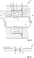
- the first machine element 12 has a seal retaining structure, here a retaining groove 20 with a high-pressure side Groove flank 20a, a groove base 20b and a low-pressure side groove flank 20c .
- the second machine element 14 has a dynamic sealing surface 22 .
- a rotating seal 24 For sealing a pressurizable with a fluid high pressure side H to a low pressure side N of the sealing gap 16 is a rotating seal 24.
- the rotating seal 24 is here designed as a so-called radial shaft sealing ring.
- the rotary seal 24 can be made in one piece and has a holding section 26 running essentially radially and a sealing lip 28 with a sealing edge 30 which extends in the axial direction from the holding section 26, here in the direction of the low-pressure side N.
- Sections of the sealing lip 28 are arranged parallel or substantially parallel to the sealing surface 22 of the second machine element 14 .
- the front side 32 of the sealing lip 28 rests against the sealing surface 22 of the second machine part 14 in a dynamically sealing manner.
- the back of the sealing lip is denoted by 34 .
- the rear side 34 of the sealing lip 28 thus points away from the sealing surface 22 in a radial direction here.
- the holding section 26 is here held clamped by means of a support ring 36 and a clamping ring 38 in the holding groove 20 of the first machine element 12 and is thereby fixed in a rotationally fixed manner on the first machine element 12 .
- Other types of attachment, such as pinning the holding section, are conceivable.
- the support ring 36 and also the holding section 26 of the rotary seal 24 each have one or more through bores 40 through which a fluidic connection of the high-pressure side H with the holding groove 20 of the first machine element 12 is made possible.
- the first machine part can have a groove designated by 42 in order to ensure an inflow of fluid to the through bores 40 on the high-pressure side.
- the holding groove 20 can thus be pressurized with an operating pressure P prevailing on the high-pressure side H during the operational use of the rotary seal arrangement 10 .
- the rotary seal 24 or its sealing lip 28 can thereby be pressure-activated.
- pressurization of the high-pressure side H with an operating pressure P leads to a contact pressure that is proportional to the operating pressure P
- the sealing lip 28 is prestressed against the sealing surface 22 by a prestressing ring 44 that can be elastically deformed.
- the prestressing ring 44 bears circumferentially on the rear side 34 of the sealing lip 28 .
- the prestressing ring 44 can in particular be designed as an elastomer or rubber ring or as a metal spring (worm spring).
- the prestressing ring 44 and the rotary seal 24 are arranged coaxially to the axis of rotation 18 and to the central axis of the rotary seal 24, which is denoted by 46 .
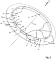
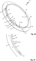
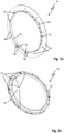
- In 2 is the rotary seal 24 of the in 1 shown rotary seal assembly 10 shown in an isolated perspective view.
- the rotary seal 24 has a return functionality for fluid, which is essentially based on a macroscopically visible surface structure 48 of the rear side 34 of the sealing lip 28 .
- the sealing lip 28 has a number of pockets 50 on its rear side 34 .
- the pockets 50 are spaced apart from one another in the circumferential direction of the rotary seal 24 .
- the pockets 50 in the sealing lip 28 are delimited on both sides by a first and a second side wall section 52, 54 of the sealing lip 28 (in the circumferential direction).
- the two side wall sections 52, 54 are therefore arranged opposite one another and face one another.
- the two side wall sections 52, 54 are each arranged to run obliquely at an acute angle ⁇ , ⁇ relative to the circumferential direction of the sealing lip 28.
- the side wall sections 52, 54 are each connected via an edge 56 to the (surface 34a of) the rear side 34 of the sealing lip 28.
- the preload ring 44 rests circumferentially on the outside of the sealing lip 28 in the radial direction and clamps the sealing lip against the sealing surface 22, the preload ring 44 in the sealing lip areas between the pockets 50, ie in the non-pockets 50 material weakened circumferential segments of the sealing lip 28, a higher radial precompression or prestressing of the sealing lip 58 generates 28 against the sealing surface 22 of the second machine part 14, than in the area of the pocketed 50 sealing lip portions 60 and bag segment of the sealing lip 28.
- This difference in the - here radially directed - prestressing or pre-pressing of the sealing lip 22 leads to a desired contact pressure distribution of the sealing lip 28 against the sealing surface 22.
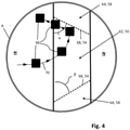
- the sealing lip 28 abuts the sealing surface 22 of the second machine part 14 in a dynamically sealing manner in the circumferential direction of the rotary seal with a contact surface pressure profile that corresponds to the spatial distribution pattern of the pockets 50 . It's according to here 3 essentially to differentiate between first sealing zones 62 of the sealing surface 22 with low contact (surface) pressure and second sealing zones 64 with greater contact pressure of the sealing lip 28 and the sealing surface 22 than the first sealing zones 62.
- the sealing lip regions 60 provided with pockets 50 are located in the first sealing zones 62 and the circumferential segments 58 of the sealing lip 28 (not provided with pockets 50) are located in the second sealing zones 64 ( 2 ) on the sealing surface 22 dynamically sealing.
- the rear surface structuring 48 of the sealing lip 28 is thus reproduced in the form of a contact pressure curve of the sealing lip 28 and the sealing surface 20 corresponding thereto in the circumferential direction.
- a fluid film formed between the sealing lip 28 and the sealing surface 22 is necessarily thinner here than in the sealing lip areas 60 provided with the pockets 50.
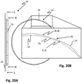
- Fluid particle designated 66 for example, when the second machine element 14 is rotating, from the high-pressure side H axially in the direction of the low-pressure side N into the sealing gap 16 between a sealing lip area 60 having a pocket 50 and the sealing surface 22, the fluid particle 66 will become linear and functionally wall-like steep Contact pressure flank 68, which corresponds to one of the sloping side wall sections 52, 54 of the pocket 50 of the sealing lip 28, flow against and thereby promoted back to the high-pressure side H.
- this return principle is illustrated in a highly schematic manner.
- the curved path line 70 of the fluid particle 66 results from the superimposition of pressure flow (oil is under pressure) and drag flow, ie the rotating machine element 14 drags the fluid along in the respective direction of rotation R 1 , R 2 or in the circumferential direction.
- angles ⁇ , ⁇ of the side wall sections relative to the circumferential direction, the number of pockets 50 and the area ratio of the sealing lip areas 60 provided with pockets 50 to non-material-weakened sealing lip segments 58 are fundamental parameters that determine the effectiveness of returning the fluid.
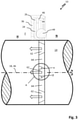
- FIG 5 is a software-generated calculation model of the rotary seal 26 according to the Figs. 1 to 3 shown in an isolated view with a single pocket 50 arranged on the rear of the sealing lip 28 .
- the calculation model also includes the other in illustration 1 illustrated components of the rotary seal assembly 10 also taken into account.
- the Calculation model enables the calculation of the contact (surface) pressure that results in the dynamic sealing surface 22 of the second machine element 14 . The result is in 6 to see graphically.
- the contact pressure p represented by arrows, of the sealing lip 28 of the rotary seal 24 is smaller (shorter arrows) than in the area between the pockets ( longer arrows). It can also be seen that the angles ⁇ , ⁇ (cf. Figure 3 ) in the pressure distribution.
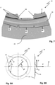
- figure 7 is an additional vector representation of the contact pressure p between the sealing lip 28 and the sealing surface 22 (cf. 1 ) shown.
- the variable course of contact pressure in the circumferential direction of the rotary seal 24 with the contact pressure flanks 68 can be clearly seen.
- the Figs. 8th show the rotary seal 24 in a frontal view ( Figure 8a ) and in a side view ( Figure 8b ) together with a cylindrical coordinate system.
- Z denotes the position on the Z-axis that coincides with the central axis 46 ( 1 ) of the rotary seal 24 coincides.
- R represents the radial distance from the center.
- the angle ⁇ denotes the circumferential position around the center.
- FIG. 9 shows a family of curves with spatially resolved contact pressure profiles along three different sections of the rotary seal 24, which are offset parallel to one another in the Z direction.
- the three sections therefore belong to three different Z-coordinates according to in Figure 8B illustrated cylindrical coordinate system.
- the family of curves is not based on a mathematical calculation of the contact pressure curves, but is to be understood as a basic representation. It can be seen that the pressure valley 72 formed by the pocket 50 becomes narrower as the Z coordinate increases (ie axially in the direction of the low-pressure side N). This is due to the fact that as the Z coordinate increases, the expansion of the pocket in the ⁇ direction (and thus in the installed state of the rotary seal 24 towards the low-pressure side N) becomes smaller.
- FIG. 10 shows a further embodiment of the rotary seal arrangement 10.
- the elastically preformable prestressing ring 44 is supported here in the radial direction on the outside directly on a support structure of the first machine element 12 having the seal retaining structure, here a modified clamping ring 38.
- the prestressing ring 44 By supporting the prestressing ring 44, the compression of the sealing lip 28 against the sealing surface 22, ie the contact pressure p of the sealing lip 28 and the sealing surface 22, can be further increased. Overall, it can be ensured over an even broader range of applications that the sealing lip 28 of the rotary seal 24 also has a non-zero contact pressure p in the area of the rear pockets 50 .
- the rotary seal arrangement 10 shown can also be used to increase the prestressing of the sealing lip 28 against the sealing surface 22 by one or more cord springs or garter spring elements 74 which surround the elastically deformable prestressing ring 44 radially on the outside.
- the preload ring 44 does not have to be an O-ring, as is the case, for example, in 10 is shown, but can according to 11 also have a different cross-sectional shape, here lobed, for example to further improve the positional stability of the cord spring(s).
- the filling of the retaining groove 20 of the first machine element 12, which serves as a seal retaining structure can also be reduced, for example for the purpose of pressurization with the operating pressure P.
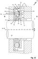
- the rotary seal arrangement 10 can also have a rotary seal 24 which seals dynamically in the axial direction in the form of an axial shaft sealing ring.
- an annular collar 76 for example in the form of an angled metal sleeve, can be arranged on the second machine part 14 in a rotationally fixed manner Sealing surface 22 forms.
- the collar 76 can be on the second machine element 14 z. B. pressed or welded to this or formed on this.
- the annular collar 76 rotates here together with the second machine element 14 about the axis of rotation 18.
- the axial shaft sealing ring can be made of PTFE or a PTFE compound.
- the pockets 50 arranged on the rear side in the sealing lip 28 can be clearly seen.
- the rear contour of the sealing lip 28 is shown in one of the non-material-weakened peripheral segments of the sealing lip 28 with a dashed line 34a.
- the first machine element 12 is designed here as a multi-part shaft housing.
- the elastically deformable prestressing ring 44 here an O-ring
- the elastically deformable prestressing ring 44 due to the pockets in the rear side 34 of the sealing lip 28, generates a contact pressure profile of the sealing lip 28 on the sealing surface that corresponds to the spatial distribution pattern of the pockets.
- the fluid entrained by the annular collar 76 experiences a deflection in a positive radial direction as a result of this contact surface pressure distribution. It is thus conveyed back to the high-pressure side H of the sealing gap 16 to be sealed.
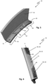
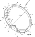
- FIG. 13 shows the axially sealing rotary seal 12 in a cropped view.
- the pockets 50 in the back 34 of the sealing lip 28 are clearly visible.
- the pockets - in relation to the central axis 46 of the rotary seal 24 - are limited in the circumferential direction by ramp-shaped or inclined side wall sections 52, 54. It is understood that such inclined side wall portions 52, 54 also in the above in connection with Figures 1 to 12 explained rotary seals 10 are possible.
- the pockets are also delimited by wall sections 78 in a direction radial to the central axis of the rotary seal 24 . These wall sections 78 can in turn also be inclined in a manner corresponding to the side wall sections 52, 54 (to the surface 34a of the rear side 34 of the sealing lip 28).
- pockets 50 provided sealing lip regions 60 of the rotary seals 24 explained above can have a free edge section 80 which is arranged on the outside in the radial direction and which is not weakened in terms of material.
- the elastically deformable prestressing ring 44 can thus also be secured in the region of the pockets 50 against slipping off the sealing lip 28, in this case radially.
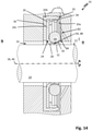
- the sealing lip 28 of the rotary seal 10 can also extend away from the holding section 26 in the direction of the high-pressure side H of the rotary seal arrangement 10 .
- the first machine element 12 having the retaining groove 20 can have a bore 82 for the additional pressure activation of the rotary seal 24, through which a fluidic connection of the high-pressure side H with the retaining groove 20 is effected.
- the retaining groove 20 can also have a groove-shaped flow channel 84 for the fluid arranged on the high-pressure side H on its groove flank 20a arranged on the high-pressure side as an alternative or in addition to the bore 82 .
- This flow channel 84 therefore runs radially in the direction of the groove bottom 20b.
- the side wall sections (52, 54; cf. 2 ) of the pockets 50 arranged on the rear side 34 of the sealing lip 28 diverge in the direction of the high-pressure side H.
- the 15 shows a rotary seal arrangement 10, in which the rotary seal 24 without a separately formed preload ring 44 on the sealing surface 22 of the second machine element 14 bears in a preloaded and sealing manner. This is due to an inherent elastic resilience of the material of the rotary seal 24 .
- the rotary seal 24 is designed here as a radial shaft sealing ring, for example. It goes without saying that the rotary seal can also be designed as an axial shaft sealing ring.
- the rotary seal 24 is with its sealing lip 28 between the first machine element 12 and the second machine element 14 - held clamped arranged - here in the radial direction.
- the rear side of the sealing lip rests with a statically sealing sealing section 84 on the first machine element 12, here by way of example the groove bottom 20b of a seal retaining structure designed as a retaining groove 20, in a statically sealing manner.
- the dynamic sealing lip 28 of the rotary seal 34 here has pockets 50 on its end face 86 facing the high-pressure side H.
- the pockets 50 are arranged at a distance from one another, preferably regularly, in the circumferential direction of the rotary seal 34 .
- the rotary seal can be pressure-activated by the operating pressure (fluid pressure) P prevailing on the high-pressure side H of the rotary seal arrangement 10 .
- the pockets 50 of the sealing lip 28 taper from the end face 86 with increasing axial depth in relation to the central axis 46 of the rotary seal 34 (in the circumferential direction).
- the side wall sections 52, 54 diverge in the direction of the high-pressure side H. Accordingly, the side wall sections 52, 54 of the pockets are also arranged here running obliquely at an angle ⁇ , ⁇ to the circumferential direction.
- the principle of fluid recirculation works here as well as in the context above Figs. 3 and 4 is explained.
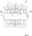
- the rotary seal arrangements 10 have two rotary seals 28 which are arranged one behind the other (along the sealing surface 22).
- the sealing lips 28 of the two rotary seals 10 can be arranged with end faces 86 facing one another, pointing away from one another, or with end faces 86 aligned in the same direction.
- the two rotary seals 34 each other have opposite return effects. 17 shows this as an example for in the Figs. 15 and 16 shown variant.
- the two rotary seals 23 can be used to separate two media spaces that can be pressurized on one side, on both sides, or on both sides.
- the rotary seal arrangement 10 can also have a single rotary seal 24 that separates media.
- This rotary seal 34 then has two sealing lips 28 which are arranged with end faces pointing away from one another.
- a rotary seal arrangement 10 with a tandem arrangement of two rotary seals 24, which correspond to one another in their return conveying direction, is also conceivable.
- the pockets 50 of the sealing lip 28 are each delimited by side wall sections 52 , 54 which have a sharp-edged transition to the (surface of) the rear side 34 of the sealing lip 28 .
- the back 34 of the sealing lip 28 may also have a wavy surface contour.
- the side wall sections 52, 54 of the pockets 50 and the surface 34a of the rear side 34 of the sealing lip 28 flow into one another.
- the sealing lip 28 for the return function of the rotary seal 24, also have additional, preferably web-like or rib-like elevations 88 on their rear side 34, through which the side wall sections 52, 54 of the pockets 50 of the sealing lip 28 protrude beyond the contour of the pocket-free peripheral segments 58 of the sealing lip 28.
- the contact pressure p of the sealing lip 28 in the side wall sections 52, 54 ( 2 ) corresponding areas of their front 32 are further reinforced.
- FIG. 22 shows a special embodiment of a rotary seal 10--here purely by way of example sealing axially--in which the pockets 50 arranged on the rear side 34 of the sealing lip 28 are additionally fluidly connected to one another via groove-shaped or notch-shaped channels 90.
- a radially sealing rotary seal 10 ie a radial shaft sealing ring, such as this example in 2 shown, may be provided with such channels 90.
- the surface structuring 48 of the rear side 34 of the sealing lip 28 of the rotary seal required for the return mechanism presented here can be produced by means of various manufacturing processes. These include, in particular, embossing processes, laser material processing, machining processes, in particular milling, and additive manufacturing processes or injection molding processes.
Description
Die Erfindung betrifft eine Rotationsdichtungsanordnung sowie eine Rotationsdichtung mit Rückförderfunktion. Die Rotationsdichtungsanordnung umfasst ein erstes und ein zweites Maschinenelement, die unter Ausbildung eines Dichtspalts voneinander beabstandet und um eine Rotationsachse relativ zueinander bewegbar angeordnet sind. Das erste Maschinenelement weist eine Dichtungshaltestruktur und das zweite Maschinenelement weist eine Dichtfläche auf. Zum Abdichten einer mit einem Fluid druckbeaufschlagbaren Hochdruckseite H des Dichtspalts gegenüber einer Niederdruckseite N des Dichtspalts dient eine Rotationsdichtung. Die Rotationsdichtung ist an der Dichtungshaltestruktur des ersten Maschinenelements gehalten angeordnet und weist eine Dichtlippe auf, die mit ihrer der Dichtfläche zuweisenden Vorderseite an der Dichtfläche des zweiten Maschinenelements dynamisch dichtend anliegt. Die Dichtlippe erstreckt sich also zumindest abschnittsweise parallel oder im Wesentlichen parallel zur Dichtfläche.The invention relates to a rotary seal arrangement and a rotary seal with a return function. The rotary seal arrangement comprises a first and a second machine element, which are spaced apart from one another to form a sealing gap and are arranged such that they can be moved relative to one another about an axis of rotation. The first machine element has a seal retaining structure and the second machine element has a sealing surface. A rotary seal is used to seal a high-pressure side H of the sealing gap, which can be pressurized with a fluid, from a low-pressure side N of the sealing gap. The rotary seal is held on the seal holding structure of the first machine element and has a sealing lip, which with its front side facing the sealing surface bears against the sealing surface of the second machine element in a dynamically sealing manner. The sealing lip thus extends at least in sections parallel or essentially parallel to the sealing surface.
Derartige Rotationsdichtungen stellen als dynamische Dichtsysteme wesentliche Konstruktionselemente im Maschinenbau sowie im Fahrzeugbau dar. Die Rotationsdichtungen werden in der Praxis als Radial- oder Axialwellendichtringe eingesetzt. Die Rotationsdichtungen sind in der Praxis nicht zuletzt aufgrund der technischen Weiterentwicklung der Aggregate immer weiter steigenden Betriebsdrücken, Temperaturen und Gleitgeschwindigkeiten ausgesetzt. Das Versagen der Rotationsdichtungen führt dabei zu einer unerwünschten Leckage des abzudichtenden Fluids, was insbesondere bei kritischen Anwendungen verheerende Folgen haben kann. Die Rotationsdichtungselemente müssen mithin immer höheren Anforderungen an deren Dichtvermögen gerecht werden und sollen dabei dennoch eine verbesserte Lebensdauer aufweisen.As dynamic sealing systems, such rotary seals represent essential design elements in mechanical engineering and in vehicle construction. The rotary seals are used in practice as radial or axial shaft sealing rings. In practice, rotary seals are exposed to ever-increasing operating pressures, temperatures and sliding speeds, not least because of the further technical development of the units. The failure of the rotary seals leads to an undesirable leakage of the fluid to be sealed, which is particularly important in critical applications can have devastating consequences. The rotary sealing elements therefore have to meet ever increasing demands on their sealing ability and should nevertheless have an improved service life.
Einer reibungsbedingten Lebensdauerverkürzung der Dichtungselemente wird in der Praxis vorrangig durch ein optimiertes Schmieren im Bereich des an der Dichtfläche anliegenden Dichtabschnitts bzw. der Dichtkante des Dichtungselements, den Einsatz von Materialpaarungen mit möglichst geringer Gleitreibung sowie einer optimierten Wärmeabfuhr im Bereich der Dichtzone entgegengewirkt. Für eine Rückförderung von Fluid können die in der Praxis eingesetzten Dichtlippen an ihrer an der Dichtfläche anliegenden Vorderseite sogenannte Tribostrukturen aufweisen. Eine Rotationsdichtungsanordnung mit einer Rotationsdichtung, deren Dichtlippe derlei Tribostrukturen an der der Dichtfläche anliegenden Vorderseite aufweist, ist beispielsweise aus der
Es ist deshalb die Aufgabe der Erfindung, eine Rotationsdichtungsanordnung anzugeben, bei der die Fluid-Rückförderfunktion weniger verschleißabhängig ist. Die die Rotationsdichtungsanordnung betreffende Aufgabe wird durch eine Rotationsdichtung mit den in Anspruch 1 angegebenen Merkmalen gelöst.It is therefore the object of the invention to specify a rotary seal arrangement in which the fluid return function is less dependent on wear. The task relating to the rotary seal arrangement is achieved by a rotary seal having the features specified in claim 1 .
Bei der erfindungsgemäßen Rotationsdichtungsanordnung weist die Dichtlippe der Rotationsdichtung an ihrer von der Dichtfläche des zweiten Maschinenelements wegweisenden Rückseite oder an ihrer Stirnseite Taschen auf. Unter einer Tasche wird vorliegend eine Einbuchtung bzw. eine Vertiefung der Dichtlippe verstanden.In the rotary seal arrangement according to the invention, the sealing lip of the rotary seal has pockets on its rear side pointing away from the sealing surface of the second machine element or on its front side. In the present case, a pocket is understood to mean an indentation or a depression in the sealing lip.
Im Falle der rückseitig an der Dichtlippe angeordneten Taschen ergibt sich im Bereich der Taschen jeweils eine lokale Dickenreduktion, d. h. eine Materialschwächung, der Dichtlippe. Bei einer stirnseitig an der Dichtlippe angeordneten Tasche ist diese von der Rückseite sowie auch von der Vorderseite der Dichtlippe beabstandet angeordnet. Die Taschen weisen in diesem Fall mithin eine zur Hochdruckseite oder zur Niederdruckseite des Dichtspalts bzw. der Dichtungsanordnung weisende (gerichtete) Öffnung auf.In the case of the pockets arranged on the back of the sealing lip, there is a local reduction in thickness in the area of the pockets, i. H. a material weakening, the sealing lip. In the case of a pocket arranged on the face side of the sealing lip, this pocket is arranged at a distance from the back and also from the front of the sealing lip. In this case, the pockets therefore have an opening pointing (directed) towards the high-pressure side or towards the low-pressure side of the sealing gap or the sealing arrangement.
Die Taschen der Dichtlippe sind in Umfangsrichtung der Rotationsdichtung voneinander beabstandet an der Dichtlippe angeordnet. Somit ist den Taschen in Umfangsrichtung der Rotationsdichtung bzw. der Dichtlippe jeweils ein nichtmaterialgeschwächtes Umfangssegment der Dichtlippe zwischengeschaltet angeordnet.The pockets of the sealing lip are arranged on the sealing lip spaced apart from one another in the circumferential direction of the rotary seal. Thus, a circumferential segment of the sealing lip that is not weakened in material is arranged in between the pockets in the circumferential direction of the rotary seal or the sealing lip.
Bei der Ausführungsform der Rotationsdichtung mit rückseitig angeordneten Taschen ist die Dichtlippe der Rotationsdichtung durch einen elastisch, bevorzugt gummielastisch, verformbaren Vorspannring gegen die Dichtfläche des zweiten Maschinenelements gespannt. Ist die Rotationsdichtung als ein Radialwellendichtring ausgeführt, so wird die Dichtlippe durch den Vorspannring mithin in einer zur Bewegungsachse radialen Richtung gegen die Dichtfläche vorgespannt. Im Falle einer als Axialwellendichtring ausgebildeten Rotationsdichtung ist die Dichtlippe durch den Vorspannring dementsprechend in axialer Richtung gegen die Dichtfläche des zweiten Maschinenelements vorgespannt. Der Vorspannring ist dabei zur Rotationsdichtung vorzugsweise separat ausgebildet.In the embodiment of the rotary seal with pockets arranged on the rear, the sealing lip of the rotary seal is tensioned against the sealing surface of the second machine element by an elastically, preferably rubber-elastic, deformable pretensioning ring. If the rotary seal is designed as a radial shaft sealing ring, the sealing lip is thus prestressed by the prestressing ring in a direction radial to the movement axis against the sealing surface. In the case of a rotary seal designed as an axial shaft sealing ring, the sealing lip is correspondingly prestressed in the axial direction against the sealing surface of the second machine element by the prestressing ring. The prestressing ring is preferably designed separately from the rotary seal.
Der Vorspannring kann nach der Erfindung insbesondere in Form einer Wurmfeder oder eines Gummi- bzw. Elastomerrings ausgebildet sein. Der Gummi- oder Elastomerring kann eine kreiszylindrische, eine elliptische oder ovale Querschnittsform oder auch einen Freiform-Querschnitt aufweisen. Der Vorspannring kann am ersten Maschinenelement oder einem Anbauteil des ersten Maschinenelements abgestützt sein. Auch kann der Vorspannring, etwa durch ein oder mehrere Wurmfedern, zusätzlich in Richtung auf die Dichtfläche des zweiten Maschinenteils vorgespannt sein.According to the invention, the preloading ring can be designed in particular in the form of a garter spring or a rubber or elastomer ring. The rubber or elastomer ring can have a circular-cylindrical, an elliptical or oval cross-section or a free-form cross-section. The preload ring can on the first machine element or an attachment of the first Be supported machine element. The preload ring can also be preloaded in the direction of the sealing surface of the second machine part, for example by one or more garter springs.
Die Taschen der Dichtlippe sind in Umfangsrichtung der Rotationsdichtung jeweils (zumindest zu einer Seite hin) durch einen Seitenwandabschnitt der Dichtlippe seitlich begrenzt, der relativ zur Umfangsrichtung zumindest abschnittsweise unter einem spitzen Winkel α, β in Richtung auf die Hochdruckseite H schräg verlaufend angeordnet ist, derart, dass die Dichtlippe an der Dichtfläche in Umfangsrichtung mit einem zur Oberflächenstrukturierung der Rückseite der Dichtlippe, d. h. zum räumlichen Verteilungsmuster ihrer Taschen, korrespondierenden Kontaktpressungsverlauf an der Dichtfläche des zweiten Maschinenelements anliegt, durch den bei einer Relativbewegung der beiden Maschinenteile um die Rotationsachse eine zur Hochdruckseite gerichtete Rückförderung von Fluid bewirkt ist, welches zwischen die Dichtlippe und die Dichtfläche gelangt ist.The pockets of the sealing lip are laterally delimited in the circumferential direction of the rotary seal (at least on one side) by a side wall section of the sealing lip, which relative to the circumferential direction is arranged at least in sections at an acute angle α, β running obliquely in the direction of the high-pressure side H, such that the sealing lip on the sealing surface in the circumferential direction with a surface structuring of the back of the sealing lip, d. H. to the spatial distribution pattern of their pockets, corresponding contact pressure curve on the sealing surface of the second machine element, through which a relative movement of the two machine parts around the axis of rotation causes a return of fluid directed to the high-pressure side, which has got between the sealing lip and the sealing surface.
Bei der erfindungsgemäßen Rotationsdichtungsanordnung sind die für das Rückfördervermögen der Rotationsdichtung wesentlichen Dichtlippenstrukturen mithin nicht an der dynamisch dichtenden Vorderseite der Dichtlippe angeordnet, die im Betriebseinsatz einem thermischen bzw. mechanischen Verschleiß unterliegt. Vielmehr sind diese Strukturen bei der erfindungsgemäßen Rotationsdichtung in Bereichen der Dichtlippe angeordnet, die während des Betriebseinsatzes der Rotationsdichtungsanordnung von der Dichtfläche des zweiten Maschinenelements beabstandet angeordnet sind. Diese Dichtlippenstrukturen sind somit während des Betriebseinsatzes der Rotationsdichtungsanordnung ohne einen direkten mechanischen Kontakt zur dynamischen Dichtfläche und unterliegen dadurch keinem unmittelbaren reibungsbedingten Verschleiß. Verschleißanfällige Tribostrukturen an der der Dichtfläche zweisenden Vorderseite der Dichtlippe können sich dadurch vollständig erübrigen.In the rotary seal arrangement according to the invention, the sealing lip structures that are essential for the return capacity of the rotary seal are therefore not arranged on the dynamically sealing front side of the sealing lip, which is subject to thermal or mechanical wear during operation. Rather, in the rotary seal according to the invention, these structures are arranged in areas of the sealing lip that are arranged at a distance from the sealing surface of the second machine element during operational use of the rotary seal arrangement. These sealing lip structures are therefore not in direct mechanical contact with the dynamic sealing surface during operational use of the rotary seal arrangement and are therefore not subject to any direct wear caused by friction. Wear-prone tribological structures on the front side of the sealing lip, which faces the sealing surface, can thus be completely dispensed with.
Insgesamt kann dadurch eine effiziente Rückförderung von Fluid über eine längere Einsatzzeit der Rotationsdichtungsanordnung bzw. für Betriebseinsätze mit größeren relativen Umfangsgeschwindigkeiten der beiden Maschinenelemente bzw. bei höheren Betriebsdrücken gewährleistet werden, als dies bei Rotationsdichtungsanordnungen mit herkömmlichen Tribostrukturen an der der Dichtfläche zuweisenden Vorderseite der Dichtlippe möglich ist. Durch das erfindungsgemäße Rückförderprinzip kann zudem eine geringere Leckage, insbesondere bei längeren Laufzeiten der Rotationsdichtungsanordnungen, realisiert werden, als dies mit bisher verfügbaren Rotationsdichtungen möglich ist. Auch kann durch den bewirkten Fluidstrom zur Hochdruckseite mittelbar oder unmittelbar eine Kühlung der Dichtlippe im Bereich ihres Kontaktflächenbereichs mit der Dichtfläche und dadurch einer thermischen Überbeanspruchung der Dichtlippe sowie auch des Fluids entgegengewirkt werden. Bei Einsatz eines Ölfluids kann dadurch zudem einer unerwünschten Ölkohlebildung entgegengewirkt werden.Overall, this can ensure efficient return of fluid over a longer period of use of the rotary seal arrangement or for operational use with greater relative peripheral speeds of the two machine elements or at higher operating pressures than is possible with rotary seal arrangements with conventional tribological structures on the front side of the sealing lip facing the sealing surface . In addition, due to the recirculation principle according to the invention, less leakage can be achieved, in particular with longer running times of the rotary seal arrangements, than is possible with previously available rotary seals. The resulting fluid flow to the high-pressure side can also directly or indirectly cool the sealing lip in the area of its contact surface area with the sealing surface and thereby counteract thermal overloading of the sealing lip and also the fluid. If an oil fluid is used, an undesired formation of oil carbon can also be counteracted.
Im Falle der rückseitig an der Dichtlippe der Rotationsdichtung angeordneten Vertiefungen bzw. Taschen liegt der Vorspannring erfindungsgemäß an der Rückseite der Dichtlippe umlaufend an. Der Vorspannring aktiviert in diesem Fall den Rückfördermechanismus, indem dieser eine durch die Oberflächenstrukturierung der Rückseite der Dichtlippe, d. h. die Rückförderstrukturen, vorgegebene räumliche Kontaktpressungsverteilung der Dichtlippe an der dynamischen Dichtfläche erzeugt. Durch die elastische Vorspannung der Dichtlippe gegen die Dichtfläche wird im Bereich zwischen den Einbuchtungen bzw. Taschen, d.h. in den nicht-materialgeschwächten Umfangsabschnitten der Dichtlippe der Rotationsdichtung, jeweils eine größere Vorpressung der Dichtlippe gegen die Dichtfläche erzeugt, als in den mit den Einbuchtungen bzw. Taschen versehenen Dichtlippenabschnitten. Der Effekt kann zusätzlich durch eine zusätzliche Druckaktivierung der Rotationsdichtung bzw. deren Dichtlippe verstärkt werden. Dieser Unterschied in der Vorpressung führt zu der hier gewünschten Kontaktpressungsverteilung der Dichtlippe an der Dichtfläche, die die gleiche Wirkung hat, wie eine gegenständliche schräge Wand, die durch ein Fluid bewegt bzw. vom Fluid angeströmt wird. Da in Umfangsrichtung der Rotationsdichtung zwischen den Taschen ein höherer Pressungsdruck des Vorspannrings gegen die Dichtlippe und somit der Dichtlippe gegen die Dichtfläche vorliegt, ist der Fluidfilm hier zwangsläufig dünner als in denjenigen Umfangsabschnitten der Dichtlippe, die durch die Einbuchtungen bzw. Taschen geschwächt sind. Der sogenannte Leckagestrom V̇ des Fluids im Bereich des Kontaktflächenbereichs der Dichtlippe und der Dichtfläche wächst bekanntlich kubisch mit der Schmierfilmdicke d. h., V̇ ~h3. Insoweit wird der Leckagestrom V̇ des Fluids zwischen der Dichtlippe und der Dichtfläche des zweiten Maschinenelements hauptsächlich im Bereich der Taschen stattfinden. Strömt ein Fluidteilchen bei einer Rotationsbewegung der beiden Maschinenelemente relativ zueinander, d.h. etwa bei Rotation des als Welle ausgeführten zweiten Maschinenelements, in den Dichtspalt unter einer Tasche, wird das Fluidteilchen auf die durch den zur Umfangsrichtung der Rotationsdichtung bzw. zur Rotationsrichtung der Maschinenelemente schräg verlaufenden Seitenwandabschnitt der Tasche gebildete Kontaktpressungsflanke mit in Umfangsrichtung der Rotationsdichtung steil ansteigender Kontaktpressung, mithin die "Kontaktpressungswand" zwischen einer Kontaktpressungszone mit niedrigem und einer Kontaktpressungszone mit hohem Kontaktpressungsdruck, treffen und durch diese zurück in Richtung auf die Hochdruckseite der Rotationsdichtungsanordnung befördert. Weisen die rückseitigen Taschen der Dichtlippe jeweils nur eine zur Umfangsrichtung unter einem spitzen Winkel schräg verlaufene Seitenwand auf, die die Taschen jeweils in derselben Richtung seitlich begrenzen, so ist die Rückförderfunktion der Rotationsdichtung ersichtlich drehrichtungsabhängig. Im Falle einer als Radialwellendichtring ausgebildeten Rotationsdichtung weist die Rotationsdichtung eine axial zur Hochdruckseite H weisende Rückförderrichtung auf. Im Falle einer als Axialwellendichtring ausgebildeten Rotationsdichtung ist die Rückförderrichtung - bezogen auf die Bewegungsachse der beiden Maschinenelemente - radial in Richtung auf die Hochdruckseite H gerichtet.In the case of the indentations or pockets arranged on the back of the sealing lip of the rotary seal, the prestressing ring bears circumferentially on the back of the sealing lip. In this case, the prestressing ring activates the return mechanism by generating a spatial contact pressure distribution of the sealing lip on the dynamic sealing surface that is predetermined by the surface structure of the rear side of the sealing lip, ie the return structures. Due to the elastic prestressing of the sealing lip against the sealing surface, a greater pre-compression of the sealing lip against the sealing surface is generated in the area between the indentations or pockets, i.e. in the non-material-weakened peripheral sections of the sealing lip of the rotary seal, than in the areas with the indentations or Pockets provided sealing lip sections. The effect can also be intensified by additional pressure activation of the rotary seal or its sealing lip. This difference in the pre-compression leads to the contact pressure distribution of the sealing lip on the desired here Sealing surface that has the same effect as an actual sloping wall that is moved by a fluid or that the fluid flows against. Since there is a higher pressure of the preload ring against the sealing lip and thus the sealing lip against the sealing surface in the circumferential direction of the rotary seal between the pockets, the fluid film is inevitably thinner here than in those circumferential sections of the sealing lip that are weakened by the indentations or pockets. The so-called leakage flow V̇ of the fluid in the area of the contact surface area of the sealing lip and the sealing surface increases cubically with the thickness of the lubricating film dh, V̇ ~h 3 . In this respect, the leakage flow V̇ of the fluid between the sealing lip and the sealing surface of the second machine element will mainly take place in the area of the pockets. If a fluid particle flows during a rotational movement of the two machine elements relative to one another, i.e. for example when the second machine element designed as a shaft rotates, into the sealing gap under a pocket, the fluid particle will fall onto the side wall section running obliquely to the circumferential direction of the rotary seal or to the direction of rotation of the machine elements contact pressure flank formed in the pocket with contact pressure rising steeply in the circumferential direction of the rotary seal, thus hitting the "contact pressure wall" between a contact pressure zone with low contact pressure zone and a contact pressure zone with high contact pressure pressure, and transported back through this towards the high-pressure side of the rotary seal arrangement. If the rear pockets of the sealing lip each have only one side wall running at an acute angle to the circumferential direction, which laterally delimits the pockets in the same direction, the return function of the rotary seal is evidently dependent on the direction of rotation. In the case of a rotary seal designed as a radial shaft sealing ring, the rotary seal has a return conveying direction pointing axially to the high-pressure side H. In the case of a rotary seal designed as an axial shaft sealing ring, the return conveying direction is directed radially in the direction of the high-pressure side H, in relation to the axis of movement of the two machine elements.
In Falle der stirnseitig an der Dichtlippe angeordneten Taschen liegt die Dichtlippe durch ein dem Material der Rotationsdichtung bzw. der Dichtlippe innewohnendes elastisches Rückstellvermögen an der (dynamischen) Dichtfläche vorgespannt dichtend an. Auch bei dieser Ausführungsform ist die Kontaktpressung der Dichtlippe gegen die Dichtfläche im Bereich ihrer mit den Taschen versehenen (geschwächten) Umfangsabschnitte kleiner, als in den nicht-materialgeschwächten Dichtlippenabschnitten. Ein zum Rotationsdichtungselement separat ausgebildeter (gummi-) elastisch verformbarer Vorspannring kann sich bei dieser Ausführungsform somit vollständig erübrigen. Die Dichtlippe kann sich dabei an dem ersten Maschinenelement bzw. an einem Anbauteil des ersten Maschinenelements abstützen und an diesem, insbesondere über eine Dichtkante, unmittelbar statisch dichtend anliegen. Dadurch kann ein besonders einfacher Aufbau sowie eine vereinfachte Montage der Rotationsdichtungsanordnung erreicht werden.In the case of the pockets arranged on the face side of the sealing lip, the sealing lip rests against the (dynamic) sealing surface in a pretensioned and sealing manner due to an inherent elastic resilience of the material of the rotary seal or the sealing lip. In this embodiment too, the contact pressure of the sealing lip against the sealing surface in the region of its (weakened) peripheral sections provided with the pockets is smaller than in the sealing lip sections that are not weakened in material. A (rubber) elastically deformable prestressing ring, which is designed separately from the rotary sealing element, can thus be completely dispensed with in this embodiment. The sealing lip can be supported on the first machine element or on an add-on part of the first machine element and rest directly on it in a statically sealing manner, in particular via a sealing edge. As a result, a particularly simple structure and simplified assembly of the rotary seal arrangement can be achieved.
Nach einer bevorzugten Weiterbildung der Erfindung ist die Rotationsdichtung bzw. deren Dichtlippe druckaktivierbar. Im Betriebseinsatz der Rotationsdichtungsanordnung wird die Dichtlippe somit zusätzlich durch einen auf der Hochdruckseite herrschenden Betriebs- oder Fluiddruck - druckproportional zum Betriebsdruck - gegen die Dichtlippe gespannt bzw. gepresst. In den mit Taschen versehenen Dichtlippenbereichen bildet sich dabei - durch den Betriebsdruck P bedingt- eine jeweils geringere Kontaktpressung der Dichtlippe gegen die Dichtfläche aus, als in denjenigen Dichtlippensegmenten, die nicht mit einer Tasche versehen sind. Bei Druckbeaufschlagung der Rotationsichtung mit dem hochdruckseitig herrschenden Betriebsdruck bedingt bei stirnseitig an/in der Dichtlippe angeordneten Taschen eine Kompression, d. h. Verformung, der Rotationdichtung. Die Rotationsdichtung wird in der Folge in Richtung auf die Dichtfläche verformt und mithin - druckproportional zum Betriebsdruck - gegen die Dichtfläche gepresst. Dieser Effekt ist dabei in den nicht-materialgeschwächten Umfangssegmenten der Dichtlippe größer, als in den mit Taschen versehenen und somit materialgeschwächten Dichtlippenbereichen. Bei einer als Radialwellendichtring ausgebildeten Rotationsdichtung wird diese - bevorzugt unter Abstützung an einer niederdruckseitigen Nutflanke einer als Haltenut ausgebildeten Dichtungshaltestruktur des ersten Maschinenteils - in axialer Richtung komprimiert und folglich in radialer Richtung ausweichen und so druckproportional zum Betriebsdruck P gegen die Dichtfläche des zweiten Maschinenteils gepresst. Ist die Rotationsdichtung in Form eines Axialwellendichtrings ausgeführt, so wird die Rotationsdichtung bei Druckbeaufschlagung in radialer Richtung komprimiert und infolgedessen in axialer Richtung ausweichen und so gegen die Dichtfläche des zweiten Maschinenteils gepresst.According to a preferred development of the invention, the rotary seal or its sealing lip can be pressure-activated. During operational use of the rotary seal arrangement, the sealing lip is thus additionally tensioned or pressed against the sealing lip by an operating or fluid pressure prevailing on the high-pressure side—pressure proportional to the operating pressure. In the sealing lip areas provided with pockets - due to the operating pressure P - the contact pressure of the sealing lip against the sealing surface is lower in each case than in those sealing lip segments that are not provided with a pocket. When pressure is applied to the rotary separator with the operating pressure prevailing on the high-pressure side, compression, ie deformation, of the rotary seal occurs in pockets arranged on the face side on/in the sealing lip. As a result, the rotary seal is deformed in the direction of the sealing surface and is therefore pressed against the sealing surface in proportion to the operating pressure. This effect is greater in the circumferential segments of the sealing lip that are not weakened in material than in the sealing lip areas that are provided with pockets and are therefore weakened in material. At an as When the rotary seal is configured as a radial shaft sealing ring, this rotary seal is compressed in the axial direction, preferably with support on a low-pressure side of a groove flank of a seal retaining structure configured as a retaining groove, and consequently deflects in the radial direction and is thus pressed against the sealing surface of the second machine part in proportion to the operating pressure P. If the rotary seal is designed in the form of an axial shaft sealing ring, the rotary seal is compressed in the radial direction when pressure is applied and consequently deflect in the axial direction and thus pressed against the sealing surface of the second machine part.
Die rückseitig bzw. stirnseitig an der Dichtlippe angeordneten Taschen können sich vorteilhaft über einen Großteil der Längserstreckung der Dichtlippe erstrecken. Dies ist für den Rückfördereffekt der Rotationsdichtung, insbesondere bei druckaktivierbarer bzw. druckaktivierter Rotationsdichtung, von Vorteil.The pockets arranged on the rear or front side of the sealing lip can advantageously extend over a large part of the longitudinal extent of the sealing lip. This is advantageous for the return effect of the rotary seal, in particular in the case of a pressure-activatable or pressure-activated rotary seal.
Ist die Rotationsdichtung mit einem Vorspannring versehen, so kann nach der Erfindung der Vorspannring druckaktivierbar sein.If the rotary seal is provided with a preload ring, the preload ring can be pressure-activatable according to the invention.
Nach der Erfindung können die Vertiefungen bzw. Taschen der Dichtlippe in Umfangsrichtung jeweils beiderseitig durch Seitenwandabschnitte der Dichtlippe seitlich begrenzt sein, die zumindest abschnittsweise, vorzugsweise insgesamt, relativ zur Umfangsrichtung der Dichtlippe unter einem spitzen Winkel α, β schräg verlaufend angeordnet sind und die in Richtung auf die Hochdruckseite der Dichtungsanordnung jeweils divergieren. Dadurch kann die Rückförderfunktion der Rotationsdichtung unabhängig von einer jeweiligen Rotationsrichtung der beiden Maschinenelemente realisiert werden. Die Taschen verjüngen sich somit in Richtung auf die Niederdruckseite in ihrer in Umfangsrichtung gemessenen Breite.According to the invention, the indentations or pockets of the sealing lip can be laterally delimited on both sides in the circumferential direction by side wall sections of the sealing lip, which are arranged at least in sections, preferably overall, running obliquely at an acute angle α, β relative to the circumferential direction of the sealing lip and which in direction diverge to the high-pressure side of the sealing arrangement. As a result, the return function of the rotary seal can be implemented independently of the respective direction of rotation of the two machine elements. The width of the pockets, measured in the circumferential direction, thus tapers towards the low-pressure side.
Mit anderen Worten sind die Seitenwände der Taschen in Richtung auf die Hochdruckseite divergent verlaufend angeordnet. Entsprechend tritt auch hier ein (Schrägungs-)Winkel α, β, der funktionell betrachtet dem "wandartigen" Kontaktpressungsanstieg der Dichtlippe gegen die Dichtfläche entspricht, auf, und welcher für die Rückförderfunktion der Rotationsdichtung maßgeblich ist. Die Taschen können nach der Erfindung insbesondere einen rechteckigen bzw. auch einen elliptischen/ovalen Querschnitt aufweisen.In other words, the side walls of the pockets are arranged to run divergently in the direction of the high-pressure side. Correspondingly, this also applies here (Skewing) angle α, β, which functionally speaking corresponds to the "wall-like" increase in contact pressure of the sealing lip against the sealing surface, and which is decisive for the return function of the rotary seal. According to the invention, the pockets can in particular have a rectangular or else an elliptical/oval cross-section.
Bei der Rotationsdichtung mit rückseitig angeordneten Taschen kann die Kontaktpressung der Dichtlippe in dem zu den Seitenwandabschnitten der Taschen korrespondierenden (fluchtenden) Bereichen der Vorderseite der Dichtlippe dadurch nochmals weiter vergrößert werden, dass die Dichtlippe an ihrer Rückseite im Bereich der Seitenwandabschnitte, vorzugsweise steg- oder rippenartige, Erhebungen oder Wülste aufweist, durch die die Seitenwandabschnitte der Taschen in einer von der Rückseite der Dichtlippe bzw. der Dichtfläche wegweisenden Richtung über die (Oberflächen-) Kontur der Rückseite bzw. der nicht-materialgeschwächten Dichtlippensegmente der Dichtlippe hinaus erhöht sind. Die Seitenwandabschnitte der Vertiefungen sind bei dieser Bauform mit anderen Worten teilweise durch Seitenflanken der Erhebungen bzw. Wülste definiert bzw. gebildet.In the case of the rotary seal with pockets arranged on the rear, the contact pressure of the sealing lip in the areas of the front side of the sealing lip that correspond (align) with the side wall sections of the pockets can be further increased by the fact that the sealing lip on its rear side in the area of the side wall sections is preferably web- or rib-like Has elevations or bulges through which the side wall sections of the pockets are raised in a direction pointing away from the back of the sealing lip or the sealing surface over the (surface) contour of the back or the non-material-weakened sealing lip segments of the sealing lip. In other words, in this design, the side wall sections of the depressions are partially defined or formed by side flanks of the elevations or beads.
Die an der Rückseite der Dichtlippe der Rotationsdichtung angeordneten Einbuchtungen bzw. Taschen können nach einer Weiterbildung der Erfindung über, vorzugsweise nut- oder kerbförmige, Aussparungen bzw. Kanäle der Dichtlippe miteinander fluidisch verbunden sein. Diese Kanäle sind somit ebenfalls an/in der Rückseite der Dichtlippe angeordnet. Im Falle einer radial dichtenden Rotationsdichtung liegt die Dichtlippe mit ihrer Vorderseite in zu den Aussparungen in radialer Richtung fluchtend angeordneten Oberflächenbereichen mit einer im Vergleich zu den nicht materialgeschwächten (dickengeschwächten) Bereichen der Dichtlippe kleineren Kontaktpressung an der Gegenlauffläche (Dichtfläche) des zweiten Maschinenelements an. Bei einer axial dichtenden Anlage der Dichtlippe der Rotationsdichtung an der Dichtfläche fluchten diese Bereiche dementsprechend in axialer Richtung mit den Aussparungen. Dadurch kann das Schmierverhalten im dynamischen Kontaktflächenbereich der Dichtlippe und der Dichtfläche des zweiten Maschinenelements weiter verbessert werden.According to a development of the invention, the indentations or pockets arranged on the back of the sealing lip of the rotary seal can be fluidically connected to one another via preferably groove-shaped or notch-shaped cutouts or channels in the sealing lip. These channels are therefore also arranged on/in the back of the sealing lip. In the case of a radially sealing rotary seal, the front side of the sealing lip rests with its front side in surface areas aligned with the recesses in the radial direction with a lower contact pressure than the non-material-weakened (thickness-weakened) areas of the sealing lip on the mating surface (sealing surface) of the second machine element. When the sealing lip of the rotary seal rests against the sealing surface in an axially sealing manner, these areas are correspondingly aligned in the axial direction with the recesses. As a result, the lubricating behavior be further improved in the dynamic contact area of the sealing lip and the sealing surface of the second machine element.
Die Rotationsdichtungsanordnung kann erfindungsgemäß zwei oder auch mehr Rotationsdichtungen aufweisen. Diese können einander entgegengerichtete Rückförderfunktion oder aber im Sinne einer Tandemdichtung eine gleichgerichtete Rückförderfunktion für das Fluid aufweisen. Im erstgenannten Fall kann auch bei einer wechselweisen Druckbeaufschlagung der Hochdruckseite und der Niederdruckseite mit einem Betriebsdruck P eine zuverlässige Rückförderung des Fluids zur jeweilig druckbeaufschlagten Seite erreicht werden.According to the invention, the rotary seal arrangement can have two or more rotary seals. These can have opposing return functions or, in the sense of a tandem seal, a return function for the fluid in the same direction. In the former case, a reliable return of the fluid to the pressurized side can also be achieved when the high-pressure side and the low-pressure side are pressurized alternately with an operating pressure P.
Zu beachten ist des Weiteren, dass die Rotationsdichtung sowie der ggf. vorhandene Vorspannring bzw. weitere Anbauteile der Rotationsdichtungsanordnung in einer an sich bekannten Kartusche angeordnet sein können. Dadurch kann die Bereitstellung der Rotationsdichtung sowie die Montage der Rotationsdichtungsanordnung bei Bedarf weiter vereinfacht werden.It should also be noted that the rotary seal and the preload ring that may be present or other add-on parts of the rotary seal arrangement can be arranged in a cartridge that is known per se. As a result, the provision of the rotary seal and the assembly of the rotary seal arrangement can be further simplified if required.
Wie vorstehend bereits erläutert, kann die Rotationsdichtung, bezogen auf die Rotationsachse, in axialer oder in radialer Richtung dichtend ausgeführt sein. Im erstgenannten Fall ist die Rotationsdichtung als ein Axialwellendichtring und im letztgenannten Fall als ein Radialwellendichtring ausgeführt. Ist die Rotationsdichtung als ein Radialwellendichtring ausgeführt, kann in radialer Richtung dynamisch innendichtend oder außendichtend ausgeführt sein.As already explained above, the rotary seal can be designed to seal in the axial or radial direction with respect to the axis of rotation. In the former case, the rotary seal is designed as an axial shaft seal and in the latter case as a radial shaft seal. If the rotary seal is designed as a radial shaft sealing ring, it can be designed to be dynamically sealing on the inside or sealing on the outside in the radial direction.
Die Dichtlippe der Rotationsdichtung kann nach der Erfindung eine Dichtkante aufweisen, die an der Dichtfläche des zweiten Maschinenelements dynamisch dichtend anliegt.According to the invention, the sealing lip of the rotary seal can have a sealing edge which abuts the sealing surface of the second machine element in a dynamically sealing manner.
Die Rotationsdichtung kann zumindest teilweise oder vollständig aus einem gummielastisch oder zähelastisch verformbaren Material, insbesondere einem Thermoplast, wie beispielsweise Polytetrafluorethylen bzw. einem sogenannten PTFE-Compound, bestehen.The rotary seal can consist at least partially or entirely of a rubber-elastic or tough-elastic deformable material, in particular a thermoplastic such as polytetrafluoroethylene or a so-called PTFE compound.
Weitere Vorteile der Erfindung ergeben sich aus der Beschreibung und der Zeichnung. Ebenso können die vorstehend genannten und die noch weiter ausgeführten Merkmale erfindungsgemäß jeweils einzeln für sich oder zu mehreren in beliebigen Kombinationen Verwendung finden. Die gezeigten und beschriebenen Ausführungsformen sind nicht als abschließende Aufzählung zu verstehen, sondern haben vielmehr beispielhaften Charakter für die Schilderung der Erfindung.Further advantages of the invention result from the description and the drawing. Likewise, the features mentioned above and those detailed below can be used according to the invention individually or collectively in any combination. The embodiments shown and described are not to be understood as an exhaustive list, but rather have an exemplary character for the description of the invention.
In der Zeichnung zeigen:
- Fig. 1
- eine Rotationsdichtungsanordnung mit einem ersten und mit einem zweiten Maschinenelement, die mittels einer Rotationsdichtung gegeneinander abgedichtet sind, wobei die Rotationsdichtung eine Dichtlippe aufweist, die sich zumindest abschnittsweise parallel oder im Wesentlichen parallel zur Dichtfläche des zweiten Maschinenteils erstreckt, wobei die Dichtlippe an ihrer von der Dichtfläche wegweisenden Rückseite eine Oberflächenstrukturierung aufweist, die sich durch die mittels eines gummielastisch verformbaren Vorspannrings bewirkte vorgespannte dichtende Anlage der Dichtlippe in Form eines in Umfangsrichtung der Rotationsdichtung zur Oberflächenstrukturierung korrespondierenden Kontaktpressungsverlaufs abgebildet ist, durch die bei einer Rotation der beiden Maschinenelemente relativ zueinander eine zur Hochdruckseite H der Rotationsdichtungsanordnung gerichtete Fluidrückförderung bewirkt ist, und wobei die Rotationsdichtung druckaktivierbar ist, in einer teilweise geschnittenen ausschnittsweisen Darstellung;
- Fig. 2
- die Rotationsdichtung der Rotationsdichtungsanordnung gemäß
Fig. 1 in einer freigestellten perspektivischen Ansicht; - Fig. 3
- die Rotationsdichtungsanordnung gemäß
Fig. 1 in einer ausschnittsweisen Darstellung mit schematisch wiedergegebenem Kontaktpressungsverlauf der Dichtlippe und der Dichtfläche; - Fig. 4
- eine Detaildarstellung des in
Fig. 3 mit A bezeichneten Ausschnitts mit schematischer Darstellung der Fluid-Rückförderfunktion der Rotationsdichtung; - Fig. 5
- ein softwaregestützt mittels eines Computers erzeugtes Berechnungsmodell der Rotationsdichtung gemäß
Fig. 1 , in einer perspektivischen Ansicht - Fig. 6
- eine Darstellung des Berechnungsmodells aus
Fig. 5 mit grafischer Darstellung des rechnerisch ermittelten Kontaktpressungsverlaufs im Bereich der Dichtlippe der Rotationsdichtung im Einbauzustand bei einer Rotationsdichtungsanordnung gemäßFig. 1 , in einer perspektivischen Ansicht; - Fig. 7
- eine Darstellung des Berechnungsmodells aus
Fig. 5 mit grafischer Darstellung des rechnerisch ermittelten Kontaktpressungsverlaufs im Bereich der Dichtlippe der Rotationsdichtung im Einbauzustand bei einer Rotationsdichtungsanordnung gemäßFig. 1 , in einer Seitenansicht; - Fign. 8
- die Rotationsdichtung gemäß
Fig. 2 in einer Draufsicht (Fig. 8A ) sowie in einer Seitenansicht mit einem zylindrischen Koordinatensystem; - Fig. 9
- eine Kurvenschar mit Darstellung des räumlichen Verlaufs der Kontaktpressung in Umfangsrichtung der Rotationsdichtung entlang dreier paralleler Schnitte der Dichtlippe der Rotationsdichtung, die gemäß
Fig. 8B in Richtung der Z-Achse hintereinanderliegend angeordnet sind; - Fig. 10
- eine weitere Rotationsdichtungsanordnung, bei der der elastisch verformbare Vorspannring der Dichtlippe zusätzlich in radialer Richtung außenseitig abgestützt ist, um die Verpressung der Dichtlippe gegen die Dichtfläche des zweiten Maschinenteils zu vergrößern, in einer ausschnittsweisen Schnittdarstellung;
- Fig. 11
- eine weitere Rotationsdichtungsanordnung mit einem Vorspannring, der eine von einer kreisförmigen Querschnittsform abweichende Querschnittsform aufweist, in einer ausschnittsweisen Schnittdarstellung;
- Fig. 12
- eine weitere Rotationsdichtungsanordnung mit einer in axialer Richtung dichtenden Rotationsdichtung, in einer ausschnittsweisen Schnittdarstellung;
- Fig. 13
- die Rotationsdichtung der in
Fig. 12 gezeigten Rotationsdichtungs-anordnung, in einer freigestellten perspektivischen Ansicht; - Fig. 14
- eine weitere Rotationsdichtungsanordnung, bei der die Dichtlippe der Rotationsdichtung zusätzlich druckaktivierbar ist, in einer ausschnittsweisen Schnittdarstellung;
- Fig. 15
- eine weitere Rotationsdichtungsanordnung mit einer Rotationsdichtung, die an ihren Stirnseiten mit Taschen versehen ist, die in Umfangsrichtung voneinander beabstandet angeordnet sind, wobei die Dichtlippe druckaktivierbar ist, in einer ausschnittsweisen Schnittdarstellung;
- Fig. 16
- die Rotationsdichtung gemäß
Fig. 15 in einer freigestellten Schnittdarstellung; - Fig. 17
- eine Rotationsdichtungsanordnung mit zwei Rotationsdichtungen, durch die im Betriebseinsatz eine bidirektionale Rückförderung des Fluids bei wechselweiser Druckbeaufschlagung der Hochdruckseite H und der Niederdruckseite N bewirkt ist;
- Fig. 18
- eine Ausführungsform einer Rotationsdichtung, bei der die Oberflächenstrukturierung der Rückseite der Dichtlippe einen fließenden Übergang zwischen den durch Taschen materialgeschwächten Dichtlippenbereichen und nicht-materialgeschwächten Dichtlippensegmenten aufweist; in einer freigestellten perspektivischen Ansicht;
- Fig. 19
- eine ausschnittsweise vergrößerte Detaildarstellung der Rotationsdichtung gemäß
Fig. 18 ; - Fign. 20
- eine Seitenansicht (
Fig. 20A ) und eine detailvergrößerte Ansicht (Fig. 20B ) der Rotationsdichtung gemäßFig. 18 ; - Fig. 21
- eine Rotationsdichtung, deren Dichtlippe rückseitig angeordnete Taschen und zusätzliche Erhebungen aufweist, um die Kontaktpressung der Dichtlippe gegen die dynamische Dichtfläche an vorgegebenen Bereichen lokal zu vergrößern; und
- Fig. 22
- eine Rotationsdichtung, bei der die rückseitig an der Dichtlippe angeordneten Taschen durch Kanäle miteinander verbunden sind.
- 1
- a rotary seal arrangement with a first and a second machine element, which are sealed from one another by means of a rotary seal, the rotary seal having a sealing lip which extends at least in sections parallel or essentially parallel to the sealing surface of the second machine part, the sealing lip extending at its end from the sealing surface groundbreaking rear side has a surface structure, which is represented by the prestressed sealing contact of the sealing lip caused by means of a rubber-elastic deformable prestressing ring in the form of a contact pressure profile corresponding to the surface structure in the circumferential direction of the rotary seal, through which, when the two machine elements rotate relative to one another, one of the high-pressure side H of the Rotary seal assembly directed fluid return is effected, and wherein the rotary seal is pressure-activatable, in a partially cut cutout actual representation;
- 2
- the rotary seal according to the rotary seal arrangement
1 in a cut-out perspective view; - 3
- the rotary seal arrangement according to
1 in a sectional representation with a schematically reproduced contact pressure curve of the sealing lip and the sealing surface; - 4
- a detailed representation of the in
3 A section with a schematic representation of the fluid return function of the rotary seal; - figure 5
- a software-supported calculation model generated by a computer according to the rotary seal
1 , in a perspective view - 6
- a representation of the calculation model
figure 5 with graphic representation of the calculated contact pressure profile in the area of the sealing lip of the rotary seal in the installed state in a rotary seal arrangement according to1 , in a perspective view; - 7
- a representation of the calculation model
figure 5 with graphic representation of the calculated contact pressure profile in the area of the sealing lip of the rotary seal in the installed state in a rotary seal arrangement according to1 , in a side view; - Figs. 8th
- the rotary seal according to
2 in a plan view (Figure 8A ) and in a side view with a cylindrical coordinate system; - 9
- a set of curves showing the spatial course of the contact pressure in the circumferential direction of the rotary seal along three parallel sections of the sealing lip of the rotary seal, according to
Figure 8B arranged in series in the Z-axis direction; - 10
- a further rotary seal arrangement, in which the elastically deformable prestressing ring of the sealing lip is additionally supported on the outside in the radial direction in order to increase the compression of the sealing lip against the sealing surface of the second machine part, in a partial sectional view;
- 11
- a further rotary seal arrangement with a preload ring, which has a cross-sectional shape deviating from a circular cross-sectional shape, in a partial sectional view;
- 12
- a further rotary seal arrangement with a rotary seal that seals in the axial direction, in a partial sectional view;
- 13
- the rotary seal of the in
12 rotary seal arrangement shown, in a cut-out perspective view; - 14
- a further rotary seal arrangement, in which the sealing lip of the rotary seal can also be pressure-activated, in a partial sectional view;
- 15
- a further rotary seal arrangement with a rotary seal which is provided on its end faces with pockets which are arranged at a distance from one another in the circumferential direction, the sealing lip being pressure-activatable, in a partial sectional view;
- 16
- the rotary seal according to
15 in a cut-out sectional view; - 17
- a rotary seal arrangement with two rotary seals, through which a bidirectional return of the fluid is effected during operation when the high-pressure side H and the low-pressure side N are pressurized alternately;
- 18
- an embodiment of a rotary seal, in which the surface structuring of the rear side of the sealing lip has a smooth transition between the sealing lip areas that are material-weakened by pockets and the sealing lip segments that are not material-weakened; in a cut-out perspective view;
- 19
- according to FIG
18 ; - Figs. 20
- a side view (
Figure 20A ) and an enlarged view (Figure 20B ) according to therotary seal 18 ; - 21
- a rotary seal, the sealing lip of which has pockets arranged on the rear and additional elevations in order to locally increase the contact pressure of the sealing lip against the dynamic sealing surface in predetermined areas; and
- 22
- a rotary seal in which the pockets arranged on the back of the sealing lip are connected to one another by channels.
Der Stützring 36 sowie auch der Halteabschnitt 26 der Rotationsdichtung 24 weisen jeweils eine oder mehrere Durchgangsbohrungen 40 auf, durch die eine fluidische Verbindung der Hochdruckseite H mit der Haltenut 20 des ersten Maschinenelements 12 ermöglicht ist. Das erste Maschinenteil kann bei Bedarf eine mit 42 bezeichnete Nut aufweisen, um einen hochdruckseitigen Zustrom von Fluid zu den Durchgangsbohrungen 40 zu gewährleisten. Die Haltenut 20 ist dadurch während des Betriebseinsatzes der Rotationsdichtungsanordnung 10 mit einem auf der Hochdruckseite H herrschenden Betriebsdruck P druckbeaufschlagbar. Die Rotationsdichtung 24 bzw. deren Dichtlippe 28 ist dadurch druckaktivierbar. Mit anderen Worten führt eine Druckbeaufschlagung der Hochdruckseite H mit einem Betriebsdruck P zu einer zum Betriebsdruck P druckproportionalen Anpressung der Dichtlippe 28 gegen die Dichtfläche 22 in einer - hier -zur Rotationsachse 18 radialen Richtung. Die Dichtlippe 28 ist durch einen gummielastisch verformbaren Vorspannring 44 gegen die Dichtfläche 22 vorgespannt. Der Vorspannring 44 liegt an der Rückseite 34 der Dichtlippe 28 umlaufend an. Der Vorspannring 44 kann insbesondere als ein Elastomer- oder Gummiring bzw. als eine Metallfeder (Wurmfeder) ausgeführt sein. Der Vorspannring 44 und die Rotationsdichtung 24 sind zur Rotationsachse 18 bzw. zu der mit 46 bezeichneten Mittelachse der Rotationsdichtung 24 koaxial angeordnet.The
In
Die Rotationsdichtung 24 weist eine Rückförderfunktionalität für Fluid auf, die im Wesentlichen auf einer makroskopisch sichtbaren Oberflächenstrukturierung 48 der Rückseite 34 der Dichtlippe 28 basiert. So weist die Dichtlippe 28 an ihrer Rückseite 34 mehrere Taschen 50 auf. Die Taschen 50 sind in Umfangsrichtung der Rotationsdichtung 24 voneinander beabstandet angeordnet. Gemäß
Dadurch, dass der elastisch verformbare Vorspannring 44 an der Dichtlippe 28 in radialer Richtung außenseitig umlaufend anliegt und die Dichtlippe gegen die Dichtfläche 22 spannt, wird durch den Vorspannring 44 in den Dichtlippenbereichen zwischen den Taschen 50 , d. h. in den nicht durch Taschen 50 materialgeschwächten Umfangssegmenten 58 der Dichtlippe 28 , eine höhere radiale Vorpressung bzw. Vorspannung der Dichtlippe 28 gegen die Dichtfläche 22 des zweiten Maschinenteils 14 erzeugt, als im Bereich der mit Taschen 50 versehenen Dichtlippenbereiche 60 bzw. Taschensegment der Dichtlippe 28. Dieser Unterschied in der - hier radial gerichteten - Vorspannung bzw. Vorpressung der Dichtlippe 22 führt zu einer hier gewünschten Kontaktpressungsverteilung der Dichtlippe 28 gegen die Dichtfläche 22.Due to the fact that the elastically
Die Dichtlippe 28 liegt dadurch in Umfangsrichtung der Rotationsdichtung mit einem zum räumlichen Verteilungsmuster der Taschen 50 korrespondierenden Kontaktflächenpressungsverlauf an der Dichtfläche 22 des zweiten Maschinenteils 14 dynamisch dichtend an. Es ist hier gemäß
In den ersten Dichtzonen 62 liegen die mit Taschen 50 versehenen Dichtlippenbereiche 60 und in den zweiten Dichtzonen 64 die nicht mit Taschen 50 versehenen Umfangssegmente 58 der Dichtlippe 28 (
Aufgrund der größeren dichtflächenseitigen Kontaktpressung der nicht-materialgeschwächten Umfangssegmente 58 der Dichtlippe 28 im Bereich der zweiten Dichtzonen 64 der Dichtfläche 22 ist ein zwischen der Dichtlippe 28 und der Dichtfläche 22 ausgebildeter Fluidfilm hier zwangsläufig dünner, als in den mit den Taschen 50 versehenen Dichtlippenbereichen 60. Nachdem ein - hier axial gerichteter - Leckagestrom V̇ des Fluids von der Hochdruckseite H auf die Niederdruckseite N der Rotationsdichtungsanordnung 10 (
Strömt ein in
Die Winkel α, β der Seitenwandabschnitte relativ zur Umfangsrichtung, die Anzahl der Taschen 50 und das Flächenverhältnis der mit Taschen 50 versehenen Dichtlippenbereiche 60 zu nicht materialgeschwächten Dichtlippensegmenten 58 sind grundlegende Parameter, die die Effektivität der Rückförderung des Fluids bestimmen.The angles α, β of the side wall sections relative to the circumferential direction, the number of
In
In
Die
Gemäß der in
Die Rotationsdichtungsanordnung 10 kann, wie vorstehend erläutert, auch eine in axialer Richtung dynamisch dichtende Rotationsdichtung 24 in Form eines Axialwellendichtrings aufweisen. Gemäß
Das erste Maschinenelement 12 ist hier als ein mehrteiliges Wellengehäuse ausgeführt. Wie auch bei den vorstehend erläuterten Ausführungsvarianten der Rotationsdichtungsanordnung 10 erzeugt der elastisch verformbare Vorspannring 44, hier ein O-Ring, aufgrund der Taschen in der Rückseite 34 der Dichtlippe 28 einen zum räumlichen Verteilungsmuster der Taschen korrespondierendes Kontaktpressungsverlauf der Dichtlippe 28 an der Dichtfläche. Das vom Ringbund 76 mitgeschleppte Fluid erfährt durch diese Kontaktflächenpressungsverteilung eine Ablenkung in positiver radialer Richtung. Es wird somit auf die abzudichtende Hochdruckseite H des Dichtspalts 16 zurückgefördert.The
Die Dichtlippe 28 der Rotationsdichtung 10 kann sich grundsätzlich auch in Richtung auf die Hochdruckseite H der Rotationsdichtungsanordnung 10 vom Halteabschnitt 26 wegerstrecken. Gemäß dem in
Es versteht sich, dass die Haltenut 20 alternativ oder zusätzlich zur Bohrung 82 auch an ihrer hochdruckseitig angeordneten Nutflanke 20a einen nutförmigen Strömungskanal 84 für das auf der Hochdruckseite H angeordnete Fluid aufweisen kann. Dieser Strömungskanal 84 verläuft mithin radial in Richtung auf den Nutboden 20b. Zu beachten ist, dass auch hier die Seitenwandabschnitte (52, 54; vgl.
Durch den Betriebsdruck P ist im Bereich der nicht-materialgeschwächten Umfangssegmente 58 der Dichtlippe eine größere Kontaktflächenpressung der Dichtlippe 28 gegen die Gegenlauffläche, d. h. die Dichtfläche 22, bewirkt, als in den mit Taschen versehenen Dichtlippenbereichen.Due to the operating pressure P, a greater contact surface pressure of the sealing
Gemäß
Die Rotationsdichtungsanordnungen 10 weisen dazu im konstruktiv einfachsten Fall zwei Rotationsdichtungen 28 auf, die (entlang der Dichtfläche 22) hintereinanderliegend angeordnet sind. Die Dichtlippen 28 der beiden Rotationsdichtungen 10 können dabei mit einander zuweisenden, voneinander wegweisenden oder aber mit gleichsinnig ausgerichteten Stirnseiten 86 angeordnet sein. Wesentlich ist, dass die beiden Rotationsdichtungen 34 einander entgegengesetzte Rückförderwirkungen aufweisen.
Denkbar ist darüber hinaus eine Rotationsdichtungsanordnung 10 mit einer Tandemanordnung zweiter Rotationsdichtungen 24, die in ihrer Rückförderrichtung miteinander übereinstimmen.A
Bei den vorstehend erläuterten Ausführungsbeispielen sind die Taschen 50 der Dichtlippe 28 jeweils durch Seitenwandabschnitte 52, 54 begrenzt, die einen scharfkantigen Übergang zur (Oberfläche der) Rückseite 34 der Dichtlippe 28 aufweisen. Gemäß dem in den
Für die Rückförderfunktion der Rotationsdichtung 24 kann die Dichtlippe 28 gemäß des in
Die für den hier vorgestellten Rückfördermechanismus erforderliche Oberflächenstrukturierung 48 der Rückseite 34 der Dichtlippe 28 der Rotationsdichtung kann im Wege verschiedener Fertigungsverfahren erzeugt werden. Hierzu zählen insbesondere Prägeverfahren, eine Lasermaterialbearbeitung, zerspanende Verfahren, insbesondere Fräsen, sowie additive Fertigungsverfahren oder auch Spritzgussverfahren.The surface structuring 48 of the
Die vorstehend im Zusammenhang mit den
Claims (15)
- Rotary seal arrangement (10) having a recirculation function, comprising:- a first and a second machine element (12, 14), spaced apart to form a sealing gap (16) and movable relative to each other about a rotation axis (18), the first machine element (12) comprising a seal-holding structure and the second machine element (14) a sealing surface (22);- a rotary seal (24) for sealing a high pressure side H pressurizable with a fluid against a low pressure side N of the sealing gap (16), the rotary seal (24) being held on the seal-holding structure of the first machine element (12) and having a sealing lip (28), the front side (32) of which faces the sealing surface (22) and abuts at least in sections in a dynamically sealing manner against the sealing surface (22) of the second machine element (14),characterized in thatthe sealing lip (28) has pockets (50) on its rear side (34) pointing away from the sealing surface (22) or on its end face (86) facing the high-pressure side H, which are arranged spaced apart both from the rear side (34) and the front side (32) of the sealing lip (28),wherein the sealing lip (28) in case of rear side arranged pockets (50) is tensioned against the sealing surface (22) by an elastically deformable pretensioning ring (44) surrounding the sealing lip (28) on its rear side (34) circumferentially, and in case of frontally arranged pockets (50), by a resilience inherent in the material of the rotary seal,wherein the pockets (50) arranged in the circumferential direction of the rotary seal (24) are spaced apart from each other and laterally limited in the circumferential direction by a side wall portion (52, 54) of the sealing lip (28), which is arranged relative to the circumferential direction of the sealing lip (28) at least partially under an acute angle α obliquely to the high pressure side H, so that the sealing lip (28) in the circumferential direction of the rotary seal abuts the sealing surface (22) with a contact pressure profile, through which upon a relative movement of the two machine parts (12, 14) a recirculation directed to the high pressure side H of fluid passed between the sealing lip (28) and the sealing surface (22) is effected.
- Rotary seal arrangement according to claim 1, characterized in that the pockets (50) are laterally limited in the circumferential direction on both sides by a side wall portion (52, 54) of the sealing lip (28), which side wall portions are, relative to the circumferential direction of the sealing lip (28), at least partially arranged obliquely at an acute angle α, β and diverge out to the high pressure side H.
- Rotary seal arrangement according to claim 2, characterized in that the sealing lip (28) comprises on its rear side, preferably rib-like or web-like, elevations (88) through which the side wall portions (52, 54) of the pockets (50) are elevated above the contour of the rear side (34) of the sealing lip (28).
- Rotary seal arrangement according to claim 2, characterized in that the side wall portions (52, 54) of the pockets (50) are connected to the rear side (34) of the sealing lip (28) via an edge (56) or that the side wall portions (52, 54) and the rear side (34) flow smoothly into each other.
- Rotary seal arrangement according to one of the preceding claims, characterized in that the elastically deformable pretensioning ring (44) over its entire circumference rests on the rear side (34) of the sealing lip (28), in particular also in the region of the pockets (50) of the sealing lip (28).
- Rotary seal arrangement according to claim 1, characterized in that the sealing lip (28) with the frontally arranged pockets (50) statically sealing abuts the first machine part (12) with a statically sealing portion (84).
- Rotary seal arrangement according to one of the preceding claims, characterized in that the sealing lip (28) of the rotary seal (24) has a dynamic sealing edge (30).
- Rotary seal arrangement according to claim 1, characterized in that the endface pockets (50) of the sealing lip (28) of the rotary seal (24) are rectangular or oval in cross-section.
- Rotary seal arrangement according to claim 1, characterized in that pockets (50) arranged on the rear side (34) of the sealing lip (28) are fluidly connected to each other by way of, preferably groove-shaped, channels (90) of the sealing lip (28).
- Rotary seal arrangement according to one of the preceding claims, characterized in that the rotary seal (24) is dynamically sealing in the axial or in the radial direction with respect to the axis of rotation (18).
- Rotary seal arrangement according to claim 10, characterized in that the rotary seal (24) is designed to be dynamically internally sealing or externally sealing in the radial direction.
- Rotary seal arrangement according to one of the preceding claims, characterized in that the rotary seal (24) consists of a viscoelastically or rubber-elastically deformable material, in particular polytetrafluoroethylene or a polytetrafluoroethylene compound.
- Rotary seal arrangement according to claim 1, characterized in that the pretensioning ring (44) is designed as an elastomer or as a rubber ring.
- Rotary seal arrangement according to claim 1, characterized in that the rotary seal (24) comprises two sealing lips (28) extending away from the holding section (26) of the rotary seal (24) in opposite directions.
- Rotary seal arrangement according to claim 1, characterized in that the rotary seal arrangement (10) comprises a further rotary seal (24).
Priority Applications (1)
| Application Number | Priority Date | Filing Date | Title |
|---|---|---|---|
| PL18726771T PL3625484T3 (en) | 2017-05-19 | 2018-05-18 | Rotary seal arrangement and rotary seal with return function |
Applications Claiming Priority (2)
| Application Number | Priority Date | Filing Date | Title |
|---|---|---|---|
| DE102017208574.6A DE102017208574A1 (en) | 2017-05-19 | 2017-05-19 | Rotary sealing arrangement unt rotation seal with return function |
| PCT/EP2018/063092 WO2018211073A1 (en) | 2017-05-19 | 2018-05-18 | Rotary seal arrangement and rotary seal with return function |
Publications (2)
| Publication Number | Publication Date |
|---|---|
| EP3625484A1 EP3625484A1 (en) | 2020-03-25 |
| EP3625484B1 true EP3625484B1 (en) | 2022-01-19 |
Family
ID=62235945
Family Applications (1)
| Application Number | Title | Priority Date | Filing Date |
|---|---|---|---|
| EP18726771.1A Active EP3625484B1 (en) | 2017-05-19 | 2018-05-18 | Rotary seal arrangement and rotary seal with return function |
Country Status (9)
| Country | Link |
|---|---|
| US (1) | US11686389B2 (en) |
| EP (1) | EP3625484B1 (en) |
| CN (1) | CN110678677B (en) |
| DE (1) | DE102017208574A1 (en) |
| DK (1) | DK3625484T3 (en) |
| ES (1) | ES2910151T3 (en) |
| HU (1) | HUE058267T2 (en) |
| PL (1) | PL3625484T3 (en) |
| WO (1) | WO2018211073A1 (en) |
Families Citing this family (5)
| Publication number | Priority date | Publication date | Assignee | Title |
|---|---|---|---|---|
| DE102019008984A1 (en) * | 2019-12-23 | 2021-06-24 | Kaco Gmbh + Co. Kg | Shaft seal, in particular radial shaft seal, with at least one sealing element |
| CN113137476A (en) * | 2021-02-07 | 2021-07-20 | 青岛众力诚达智能科技有限公司 | Sealing structure loaded by reverse lip sealing tape pressing sealing medium |
| CN112963540A (en) * | 2021-02-07 | 2021-06-15 | 青岛众力诚达智能科技有限公司 | Rotary sealing structure with supporting lip |
| CN112963541A (en) * | 2021-02-07 | 2021-06-15 | 青岛众力诚达智能科技有限公司 | Rotary sealing structure with thread pair |
| DE202021101111U1 (en) * | 2021-03-04 | 2021-03-12 | Ews Weigele Gmbh & Co. Kg | Axial sealing ring in a driven tool |
Citations (1)
| Publication number | Priority date | Publication date | Assignee | Title |
|---|---|---|---|---|
| EP3555503A1 (en) * | 2016-12-15 | 2019-10-23 | Universität Stuttgart | Device for sealing an object |
Family Cites Families (28)
| Publication number | Priority date | Publication date | Assignee | Title |
|---|---|---|---|---|
| US3515395A (en) * | 1966-09-06 | 1970-06-02 | Gen Motors Corp | Unidirectional pumping seal |
| DE1775426A1 (en) * | 1967-08-16 | 1971-07-01 | Vare Corp | poetry |
| US3586342A (en) * | 1968-11-07 | 1971-06-22 | Dana Corp | Hydrodynamic shaft seal |
| US3785660A (en) * | 1970-10-15 | 1974-01-15 | Republic Ind Corp | Seal |
| US3861691A (en) | 1971-12-16 | 1975-01-21 | Texacone Co | Packing member |
| ZA732297B (en) * | 1972-04-10 | 1974-01-30 | Repco Res Proprietary Ltd | Improved fluid seal |
| FR2248439B1 (en) * | 1973-10-23 | 1976-10-22 | Skf Ind Trading & Dev | |
| DE3323741C2 (en) * | 1983-07-01 | 1986-07-03 | Fa. Carl Freudenberg, 6940 Weinheim | Shaft seal |
| US4484752A (en) * | 1984-03-08 | 1984-11-27 | Federal-Mogul Corporation | Rotating-lip bidirectional hydrodynamic oil seal |
| DE3526424C1 (en) | 1985-07-24 | 1987-02-12 | Freudenberg Carl Fa | Radial shaft seal and process for its manufacture |
| DE3827822A1 (en) | 1988-08-16 | 1990-02-22 | Rieter Ag Maschf | CARD WITH A CROSSBAND AT YOUR EXIT |
| US5722665A (en) * | 1992-02-26 | 1998-03-03 | Durametallic Corporation | Spiral groove face seal |
| JPH10122376A (en) * | 1996-10-14 | 1998-05-15 | Nok Corp | Oil seal |
| DE19821146A1 (en) * | 1998-05-12 | 1999-11-18 | Kaco Gmbh Co | Radial shaft seal which has a long life |
| JP3785809B2 (en) * | 1998-06-04 | 2006-06-14 | Nok株式会社 | Sealing device |
| KR100631438B1 (en) * | 1999-07-27 | 2006-10-09 | 노쓰이스트 이큅먼트, 인크. 두잉 비지니스 에즈 델타 미케니컬 씨즈 | Mechanical split seal |
| DE10000853A1 (en) * | 2000-01-12 | 2001-08-02 | Freudenberg Carl Fa | Ring seal has a sealing lip with a structured curvature and at least one opening which gives a flow link to the ambient atmosphere only on a faulty installation as an immediate indication of an incorrect fitting |
| EP1197690B1 (en) * | 2000-10-13 | 2002-10-16 | Ford Global Technologies, Inc., A subsidiary of Ford Motor Company | Sealing lip of a shaft seal |
| DE102004020965B4 (en) * | 2004-04-28 | 2015-03-05 | Carl Freudenberg Kg | Radial shaft seal |
| JP2009002510A (en) * | 2007-06-15 | 2009-01-08 | Dichtungstechnik G Bruss Gmbh & Co Kg | Sealing member for shaft and vehicle component |
| US8181966B2 (en) * | 2009-01-12 | 2012-05-22 | Kaydon Ring & Seal, Inc. | Gas seal for aerospace engines and the like |
| DE102013207029B4 (en) * | 2013-04-18 | 2016-05-04 | Aktiebolaget Skf | Radial shaft seal arrangement |
| JP6476121B2 (en) * | 2013-09-27 | 2019-02-27 | 株式会社リケン | Seal ring |
| EP3098486B1 (en) * | 2014-01-24 | 2020-03-11 | NOK Corporation | Sealing ring |
| US9458937B2 (en) * | 2014-08-14 | 2016-10-04 | Federal-Mogul Corporation | Shaft seal assembly with exclusion pump dust lip |
| DE102015226705A1 (en) * | 2015-12-23 | 2017-06-29 | Trelleborg Sealing Solutions Germany Gmbh | Sealing arrangement with sealing foil |
| WO2018097268A1 (en) * | 2016-11-25 | 2018-05-31 | Nok株式会社 | Sealing device |
| DE102017204204A1 (en) * | 2017-03-14 | 2018-09-20 | Aktiebolaget Skf | sealing arrangement |
-
2017
- 2017-05-19 DE DE102017208574.6A patent/DE102017208574A1/en not_active Withdrawn
-
2018
- 2018-05-18 WO PCT/EP2018/063092 patent/WO2018211073A1/en active Application Filing
- 2018-05-18 EP EP18726771.1A patent/EP3625484B1/en active Active
- 2018-05-18 PL PL18726771T patent/PL3625484T3/en unknown
- 2018-05-18 CN CN201880033146.2A patent/CN110678677B/en active Active
- 2018-05-18 HU HUE18726771A patent/HUE058267T2/en unknown
- 2018-05-18 DK DK18726771.1T patent/DK3625484T3/en active
- 2018-05-18 ES ES18726771T patent/ES2910151T3/en active Active
-
2019
- 2019-11-17 US US16/686,188 patent/US11686389B2/en active Active
Patent Citations (1)
| Publication number | Priority date | Publication date | Assignee | Title |
|---|---|---|---|---|
| EP3555503A1 (en) * | 2016-12-15 | 2019-10-23 | Universität Stuttgart | Device for sealing an object |
Also Published As
| Publication number | Publication date |
|---|---|
| EP3625484A1 (en) | 2020-03-25 |
| HUE058267T2 (en) | 2022-07-28 |
| CN110678677B (en) | 2021-06-29 |
| WO2018211073A1 (en) | 2018-11-22 |
| DK3625484T3 (en) | 2022-04-04 |
| PL3625484T3 (en) | 2022-05-02 |
| US11686389B2 (en) | 2023-06-27 |
| ES2910151T3 (en) | 2022-05-11 |
| US20200080643A1 (en) | 2020-03-12 |
| DE102017208574A1 (en) | 2018-11-22 |
| CN110678677A (en) | 2020-01-10 |
Similar Documents
| Publication | Publication Date | Title |
|---|---|---|
| EP3625484B1 (en) | Rotary seal arrangement and rotary seal with return function | |
| DE69630917T2 (en) | Radial flow seal for rotating shafts, which causes a turbulent flow in the sealing gap | |
| EP3596363B1 (en) | Seal assembly | |
| DE112007002983T5 (en) | Seal and sealing system | |
| DE19739472A1 (en) | Sealing arrangement | |
| EP3458746B1 (en) | Rotary seal assembly with pressure-activatable rotary seal, and rotary seal | |
| EP3394483B1 (en) | Seal arrangement with sealing film | |
| EP3583336B1 (en) | Seal arrangement with improved lubrication behavior | |
| EP0491771B1 (en) | Sealing arrangement | |
| EP3583335B1 (en) | Seal arrangement | |
| EP4148303B1 (en) | Sealing arrangement with a rod seal, dispensing device for dispensing a fluid medium and rod seal | |
| DE10140837C1 (en) | sealing arrangement | |
| EP3324083B1 (en) | Seal assembly and its use | |
| EP2607756A1 (en) | Seal with pressure relief function | |
| EP3286461A1 (en) | Piston-cylinder assembly for a piston compressor having a specific dynamically sealing piston ring | |
| EP3583337B1 (en) | Seal arrangement, and seal element with a high pressure-side flushing function | |
| DE202009010326U1 (en) | Arrangement for sealing pipes, fittings or aggregates | |
| WO1990000233A1 (en) | Sealing arrangement | |
| WO2016012136A1 (en) | High-pressure fuel pump, in particular plug-in pump | |
| EP4067706B1 (en) | Sealing ring | |
| DE102022111844B3 (en) | Shaft seal and shaft arrangement for high rotational speeds | |
| DE19610809A1 (en) | Sealing arrangement between piston and cylinder | |
| DE202016102691U1 (en) | Rotary sealing arrangement with pressure-activated rotary seal and rotary seal | |
| WO2024017779A1 (en) | Radial shaft sealing ring, radial shaft seal and radial shaft seal arrangement | |
| EP2597325B1 (en) | Sealed articulated joint |
Legal Events
| Date | Code | Title | Description |
|---|---|---|---|
| STAA | Information on the status of an ep patent application or granted ep patent |
Free format text: STATUS: UNKNOWN |
|
| STAA | Information on the status of an ep patent application or granted ep patent |
Free format text: STATUS: THE INTERNATIONAL PUBLICATION HAS BEEN MADE |
|
| PUAI | Public reference made under article 153(3) epc to a published international application that has entered the european phase |
Free format text: ORIGINAL CODE: 0009012 |
|
| STAA | Information on the status of an ep patent application or granted ep patent |
Free format text: STATUS: REQUEST FOR EXAMINATION WAS MADE |
|
| 17P | Request for examination filed |
Effective date: 20191120 |
|
| AK | Designated contracting states |
Kind code of ref document: A1 Designated state(s): AL AT BE BG CH CY CZ DE DK EE ES FI FR GB GR HR HU IE IS IT LI LT LU LV MC MK MT NL NO PL PT RO RS SE SI SK SM TR |
|
| AX | Request for extension of the european patent |
Extension state: BA ME |
|
| DAV | Request for validation of the european patent (deleted) | ||
| DAX | Request for extension of the european patent (deleted) | ||
| STAA | Information on the status of an ep patent application or granted ep patent |
Free format text: STATUS: EXAMINATION IS IN PROGRESS |
|
| STAA | Information on the status of an ep patent application or granted ep patent |
Free format text: STATUS: EXAMINATION IS IN PROGRESS |
|
| 17Q | First examination report despatched |
Effective date: 20201130 |
|
| REG | Reference to a national code |
Ref country code: DE Ref legal event code: R079 Ref document number: 502018008581 Country of ref document: DE Free format text: PREVIOUS MAIN CLASS: F16J0015320800 Ipc: F16J0015160000 |
|
| RIC1 | Information provided on ipc code assigned before grant |
Ipc: F16J 15/16 20060101AFI20210617BHEP Ipc: F16J 15/3228 20160101ALI20210617BHEP Ipc: F16J 15/3244 20160101ALI20210617BHEP Ipc: F16J 15/3208 20160101ALI20210617BHEP Ipc: F16J 15/3236 20160101ALI20210617BHEP Ipc: F16J 15/34 20060101ALI20210617BHEP |
|
| GRAP | Despatch of communication of intention to grant a patent |
Free format text: ORIGINAL CODE: EPIDOSNIGR1 |
|
| STAA | Information on the status of an ep patent application or granted ep patent |
Free format text: STATUS: GRANT OF PATENT IS INTENDED |
|
| INTG | Intention to grant announced |
Effective date: 20210809 |
|
| GRAS | Grant fee paid |
Free format text: ORIGINAL CODE: EPIDOSNIGR3 |
|
| GRAA | (expected) grant |
Free format text: ORIGINAL CODE: 0009210 |
|
| STAA | Information on the status of an ep patent application or granted ep patent |
Free format text: STATUS: THE PATENT HAS BEEN GRANTED |
|
| AK | Designated contracting states |
Kind code of ref document: B1 Designated state(s): AL AT BE BG CH CY CZ DE DK EE ES FI FR GB GR HR HU IE IS IT LI LT LU LV MC MK MT NL NO PL PT RO RS SE SI SK SM TR |
|
| REG | Reference to a national code |
Ref country code: GB Ref legal event code: FG4D Free format text: NOT ENGLISH |
|
| REG | Reference to a national code |
Ref country code: CH Ref legal event code: EP |
|
| REG | Reference to a national code |
Ref country code: DE Ref legal event code: R096 Ref document number: 502018008581 Country of ref document: DE |
|
| REG | Reference to a national code |
Ref country code: AT Ref legal event code: REF Ref document number: 1463974 Country of ref document: AT Kind code of ref document: T Effective date: 20220215 |
|
| REG | Reference to a national code |
Ref country code: IE Ref legal event code: FG4D Free format text: LANGUAGE OF EP DOCUMENT: GERMAN |
|
| REG | Reference to a national code |
Ref country code: DK Ref legal event code: T3 Effective date: 20220331 |
|
| REG | Reference to a national code |
Ref country code: SE Ref legal event code: TRGR |
|
| REG | Reference to a national code |
Ref country code: NL Ref legal event code: FP |
|
| REG | Reference to a national code |
Ref country code: LT Ref legal event code: MG9D |
|
| REG | Reference to a national code |
Ref country code: ES Ref legal event code: FG2A Ref document number: 2910151 Country of ref document: ES Kind code of ref document: T3 Effective date: 20220511 |
|
| REG | Reference to a national code |
Ref country code: HU Ref legal event code: AG4A Ref document number: E058267 Country of ref document: HU |
|
| PG25 | Lapsed in a contracting state [announced via postgrant information from national office to epo] |
Ref country code: RS Free format text: LAPSE BECAUSE OF FAILURE TO SUBMIT A TRANSLATION OF THE DESCRIPTION OR TO PAY THE FEE WITHIN THE PRESCRIBED TIME-LIMIT Effective date: 20220119 Ref country code: PT Free format text: LAPSE BECAUSE OF FAILURE TO SUBMIT A TRANSLATION OF THE DESCRIPTION OR TO PAY THE FEE WITHIN THE PRESCRIBED TIME-LIMIT Effective date: 20220519 Ref country code: NO Free format text: LAPSE BECAUSE OF FAILURE TO SUBMIT A TRANSLATION OF THE DESCRIPTION OR TO PAY THE FEE WITHIN THE PRESCRIBED TIME-LIMIT Effective date: 20220419 Ref country code: LT Free format text: LAPSE BECAUSE OF FAILURE TO SUBMIT A TRANSLATION OF THE DESCRIPTION OR TO PAY THE FEE WITHIN THE PRESCRIBED TIME-LIMIT Effective date: 20220119 Ref country code: HR Free format text: LAPSE BECAUSE OF FAILURE TO SUBMIT A TRANSLATION OF THE DESCRIPTION OR TO PAY THE FEE WITHIN THE PRESCRIBED TIME-LIMIT Effective date: 20220119 Ref country code: BG Free format text: LAPSE BECAUSE OF FAILURE TO SUBMIT A TRANSLATION OF THE DESCRIPTION OR TO PAY THE FEE WITHIN THE PRESCRIBED TIME-LIMIT Effective date: 20220419 |
|
| PG25 | Lapsed in a contracting state [announced via postgrant information from national office to epo] |
Ref country code: LV Free format text: LAPSE BECAUSE OF FAILURE TO SUBMIT A TRANSLATION OF THE DESCRIPTION OR TO PAY THE FEE WITHIN THE PRESCRIBED TIME-LIMIT Effective date: 20220119 Ref country code: GR Free format text: LAPSE BECAUSE OF FAILURE TO SUBMIT A TRANSLATION OF THE DESCRIPTION OR TO PAY THE FEE WITHIN THE PRESCRIBED TIME-LIMIT Effective date: 20220420 Ref country code: FI Free format text: LAPSE BECAUSE OF FAILURE TO SUBMIT A TRANSLATION OF THE DESCRIPTION OR TO PAY THE FEE WITHIN THE PRESCRIBED TIME-LIMIT Effective date: 20220119 |
|
| PG25 | Lapsed in a contracting state [announced via postgrant information from national office to epo] |
Ref country code: IS Free format text: LAPSE BECAUSE OF FAILURE TO SUBMIT A TRANSLATION OF THE DESCRIPTION OR TO PAY THE FEE WITHIN THE PRESCRIBED TIME-LIMIT Effective date: 20220519 |
|
| REG | Reference to a national code |
Ref country code: DE Ref legal event code: R097 Ref document number: 502018008581 Country of ref document: DE |
|
| PG25 | Lapsed in a contracting state [announced via postgrant information from national office to epo] |
Ref country code: SM Free format text: LAPSE BECAUSE OF FAILURE TO SUBMIT A TRANSLATION OF THE DESCRIPTION OR TO PAY THE FEE WITHIN THE PRESCRIBED TIME-LIMIT Effective date: 20220119 Ref country code: SK Free format text: LAPSE BECAUSE OF FAILURE TO SUBMIT A TRANSLATION OF THE DESCRIPTION OR TO PAY THE FEE WITHIN THE PRESCRIBED TIME-LIMIT Effective date: 20220119 Ref country code: RO Free format text: LAPSE BECAUSE OF FAILURE TO SUBMIT A TRANSLATION OF THE DESCRIPTION OR TO PAY THE FEE WITHIN THE PRESCRIBED TIME-LIMIT Effective date: 20220119 Ref country code: EE Free format text: LAPSE BECAUSE OF FAILURE TO SUBMIT A TRANSLATION OF THE DESCRIPTION OR TO PAY THE FEE WITHIN THE PRESCRIBED TIME-LIMIT Effective date: 20220119 |
|
| PLBE | No opposition filed within time limit |
Free format text: ORIGINAL CODE: 0009261 |
|
| STAA | Information on the status of an ep patent application or granted ep patent |
Free format text: STATUS: NO OPPOSITION FILED WITHIN TIME LIMIT |
|
| PG25 | Lapsed in a contracting state [announced via postgrant information from national office to epo] |
Ref country code: AL Free format text: LAPSE BECAUSE OF FAILURE TO SUBMIT A TRANSLATION OF THE DESCRIPTION OR TO PAY THE FEE WITHIN THE PRESCRIBED TIME-LIMIT Effective date: 20220119 |
|
| 26N | No opposition filed |
Effective date: 20221020 |
|
| PG25 | Lapsed in a contracting state [announced via postgrant information from national office to epo] |
Ref country code: MC Free format text: LAPSE BECAUSE OF FAILURE TO SUBMIT A TRANSLATION OF THE DESCRIPTION OR TO PAY THE FEE WITHIN THE PRESCRIBED TIME-LIMIT Effective date: 20220119 Ref country code: LU Free format text: LAPSE BECAUSE OF NON-PAYMENT OF DUE FEES Effective date: 20220518 |
|
| PG25 | Lapsed in a contracting state [announced via postgrant information from national office to epo] |
Ref country code: SI Free format text: LAPSE BECAUSE OF FAILURE TO SUBMIT A TRANSLATION OF THE DESCRIPTION OR TO PAY THE FEE WITHIN THE PRESCRIBED TIME-LIMIT Effective date: 20220119 |
|
| PG25 | Lapsed in a contracting state [announced via postgrant information from national office to epo] |
Ref country code: IE Free format text: LAPSE BECAUSE OF NON-PAYMENT OF DUE FEES Effective date: 20220518 |
|
| PGFP | Annual fee paid to national office [announced via postgrant information from national office to epo] |
Ref country code: SE Payment date: 20230315 Year of fee payment: 6 Ref country code: PL Payment date: 20230216 Year of fee payment: 6 |
|
| PGFP | Annual fee paid to national office [announced via postgrant information from national office to epo] |
Ref country code: NL Payment date: 20230519 Year of fee payment: 6 Ref country code: IT Payment date: 20230531 Year of fee payment: 6 Ref country code: FR Payment date: 20230517 Year of fee payment: 6 Ref country code: ES Payment date: 20230621 Year of fee payment: 6 Ref country code: DK Payment date: 20230522 Year of fee payment: 6 Ref country code: DE Payment date: 20230525 Year of fee payment: 6 Ref country code: CZ Payment date: 20230510 Year of fee payment: 6 Ref country code: CH Payment date: 20230602 Year of fee payment: 6 |
|
| P01 | Opt-out of the competence of the unified patent court (upc) registered |
Effective date: 20230630 |
|
| PGFP | Annual fee paid to national office [announced via postgrant information from national office to epo] |
Ref country code: TR Payment date: 20230515 Year of fee payment: 6 Ref country code: HU Payment date: 20230511 Year of fee payment: 6 Ref country code: AT Payment date: 20230516 Year of fee payment: 6 |
|
| PGFP | Annual fee paid to national office [announced via postgrant information from national office to epo] |
Ref country code: BE Payment date: 20230517 Year of fee payment: 6 |
|
| PGFP | Annual fee paid to national office [announced via postgrant information from national office to epo] |
Ref country code: GB Payment date: 20230522 Year of fee payment: 6 |