EP3324083B1 - Seal assembly and its use - Google Patents
Seal assembly and its use Download PDFInfo
- Publication number
- EP3324083B1 EP3324083B1 EP17201009.2A EP17201009A EP3324083B1 EP 3324083 B1 EP3324083 B1 EP 3324083B1 EP 17201009 A EP17201009 A EP 17201009A EP 3324083 B1 EP3324083 B1 EP 3324083B1
- Authority
- EP
- European Patent Office
- Prior art keywords
- sealing
- sealing ring
- sealed
- seal arrangement
- arrangement according
- Prior art date
- Legal status (The legal status is an assumption and is not a legal conclusion. Google has not performed a legal analysis and makes no representation as to the accuracy of the status listed.)
- Active
Links
- 238000007789 sealing Methods 0.000 claims description 223
- 238000009434 installation Methods 0.000 claims description 18
- 239000006096 absorbing agent Substances 0.000 claims description 11
- 230000035939 shock Effects 0.000 claims description 11
- 239000000463 material Substances 0.000 claims description 10
- 239000000945 filler Substances 0.000 claims description 7
- 238000004519 manufacturing process Methods 0.000 claims description 7
- 230000036316 preload Effects 0.000 description 14
- 238000006073 displacement reaction Methods 0.000 description 2
- 230000005489 elastic deformation Effects 0.000 description 2
- 239000000314 lubricant Substances 0.000 description 2
- 238000005461 lubrication Methods 0.000 description 2
- 238000003825 pressing Methods 0.000 description 2
- 230000004323 axial length Effects 0.000 description 1
- 238000010276 construction Methods 0.000 description 1
- 230000007423 decrease Effects 0.000 description 1
- 230000001419 dependent effect Effects 0.000 description 1
- 230000000694 effects Effects 0.000 description 1
- 238000001125 extrusion Methods 0.000 description 1
- 230000003068 static effect Effects 0.000 description 1
Images

Classifications
-
- F—MECHANICAL ENGINEERING; LIGHTING; HEATING; WEAPONS; BLASTING
- F16—ENGINEERING ELEMENTS AND UNITS; GENERAL MEASURES FOR PRODUCING AND MAINTAINING EFFECTIVE FUNCTIONING OF MACHINES OR INSTALLATIONS; THERMAL INSULATION IN GENERAL
- F16J—PISTONS; CYLINDERS; SEALINGS
- F16J15/00—Sealings
- F16J15/16—Sealings between relatively-moving surfaces
- F16J15/32—Sealings between relatively-moving surfaces with elastic sealings, e.g. O-rings
- F16J15/3204—Sealings between relatively-moving surfaces with elastic sealings, e.g. O-rings with at least one lip
- F16J15/3232—Sealings between relatively-moving surfaces with elastic sealings, e.g. O-rings with at least one lip having two or more lips
- F16J15/3236—Sealings between relatively-moving surfaces with elastic sealings, e.g. O-rings with at least one lip having two or more lips with at least one lip for each surface, e.g. U-cup packings
-
- F—MECHANICAL ENGINEERING; LIGHTING; HEATING; WEAPONS; BLASTING
- F16—ENGINEERING ELEMENTS AND UNITS; GENERAL MEASURES FOR PRODUCING AND MAINTAINING EFFECTIVE FUNCTIONING OF MACHINES OR INSTALLATIONS; THERMAL INSULATION IN GENERAL
- F16J—PISTONS; CYLINDERS; SEALINGS
- F16J15/00—Sealings
- F16J15/16—Sealings between relatively-moving surfaces
- F16J15/164—Sealings between relatively-moving surfaces the sealing action depending on movements; pressure difference, temperature or presence of leaking fluid
-
- F—MECHANICAL ENGINEERING; LIGHTING; HEATING; WEAPONS; BLASTING
- F16—ENGINEERING ELEMENTS AND UNITS; GENERAL MEASURES FOR PRODUCING AND MAINTAINING EFFECTIVE FUNCTIONING OF MACHINES OR INSTALLATIONS; THERMAL INSULATION IN GENERAL
- F16J—PISTONS; CYLINDERS; SEALINGS
- F16J15/00—Sealings
- F16J15/56—Other sealings for reciprocating rods
-
- F—MECHANICAL ENGINEERING; LIGHTING; HEATING; WEAPONS; BLASTING
- F16—ENGINEERING ELEMENTS AND UNITS; GENERAL MEASURES FOR PRODUCING AND MAINTAINING EFFECTIVE FUNCTIONING OF MACHINES OR INSTALLATIONS; THERMAL INSULATION IN GENERAL
- F16F—SPRINGS; SHOCK-ABSORBERS; MEANS FOR DAMPING VIBRATION
- F16F9/00—Springs, vibration-dampers, shock-absorbers, or similarly-constructed movement-dampers using a fluid or the equivalent as damping medium
- F16F9/32—Details
- F16F9/36—Special sealings, including sealings or guides for piston-rods
- F16F9/362—Combination of sealing and guide arrangements for piston rods
- F16F9/363—Combination of sealing and guide arrangements for piston rods the guide being mounted between the piston and the sealing, enabling lubrication of the guide
Definitions
- the invention relates to a sealing arrangement for sealing two spaces which are arranged adjacent to one another in the axial direction and are to be sealed off from one another, comprising a first machine element, a second machine element and a sealing ring, the first machine element being enclosed by the second machine element at a radial distance, and in which the Radially spaced gap of the sealing ring is arranged, wherein the sealing ring has at least one dynamically stressed first sealing lip, which sealingly surrounds a surface to be sealed of the first machine element, wherein the sealing ring is arranged in an installation space of the second machine element and wherein the sealing ring has a first and a second Has end face, of which the first end face axially faces the first space to be sealed and the second end face faces the second space to be sealed, the first space, relative to the second space, with a relative overpressure b can be opened, the second end face being designed as the first contact surface of the sealing ring, the second machine element having a second contact surface on the side axially facing the first contact surface and
- the invention also relates to the use of such a sealing arrangement.
- Such a sealing arrangement is from the DE 197 28 605 A1 known.
- the known sealing arrangement comprises a rod or piston seal, which is essentially C-shaped and is designed to be open axially in the direction of the first space to be sealed.
- the sealing lips of the sealing ring are more or less spread open in the radial direction and, with appropriate preload, they contact the surfaces of the machine elements to be sealed against each other.
- Both sealing lips are subject to dynamic loads.
- One sealing lip is sealingly supported on the boundary wall of the installation space of the second machine element, the other dynamically stressed sealing lip, on the other hand, on the surface of the first machine element to be sealed, which can be moved back and forth in the axial direction with respect to the second machine element.
- the mutually facing contact surfaces of the sealing ring and the installation space each extend in the radial direction.
- the radial pressure of the sealing lips on the surfaces to be sealed is solely dependent on the expansion of the sealing lips due to overpressure.
- In the area of the contact surface of the sealing ring there is a support bulge which is bulged radially in the direction of the first machine element and which is connected to the sealing lip arranged axially opposite by an arcuate section.
- the arcuate section comprises at least two grooves which extend in the circumferential direction and are axially adjacent to one another, webs are arranged between the grooves, which together with the grooves limit lubricant pockets.
- the sealing arrangement comprises an elastic sealing ring which can be inserted into an annular groove in one part and has a conical shell-like head part which is provided with a sealing edge.
- the foot part of the sealing ring is split into two narrow ring parts which spread elastically from one another and which end on their sides facing away from each other in a further sealing edge which interacts with a corresponding side wall of the ring groove.
- the sealing ring can have annular groove-like recesses that can be filled with lubricant.
- Another sealing arrangement is known in which an essentially triangular-shaped sealing ring is arranged in an essentially triangular-shaped installation space.
- the side walls delimiting the installation space enclose a larger angle than the walls delimiting the sealing ring.
- the sealing ring has crashed with a corner under radial preload in the V-shaped groove base of the installation space.
- the corner forms a fulcrum for the sealing ring, about which the sealing ring can be pivoted essentially in the axial direction, depending on the direction of the pressurization.
- the sealing device comprises a sealing ring which is arranged in an annular installation space.
- the installation space has one, viewed in section, V-shaped cross section.
- the sealing ring has a substantially triangular cross section, with flanks converging towards the groove base of the installation space.
- the sealing ring can be tilted around the groove base of the installation space.
- the converging flanks form a fulcrum around the groove base of the installation space, around which the sealing ring can be tilted.
- the sealing ring is installed in its rest position with a predetermined play against the inner surface of the body to be sealed, so that the distance between the pivot point of the tilting movement and the points of contact line between the sealing ring and the surface is greater under the pressure which causes the tilting movement than the largest diameter of the seal ring at rest.
- a brake cylinder seal with a recess which has a rollback function.
- the brake cylinder seal is provided for sealing a brake piston in a disc brake, a sealing ring being arranged between the brake housing and the outside diameter of the brake piston.
- the rollback function retrieves the brake piston between the brake disc and the brake pads after the brake has been actuated in order to set a predetermined clearance between the brake disc and the brake pads.
- the sealing ring has a rectangular cross-sectional area and sits in a sealing groove of the housing saddle.
- the sealing ring has so-called relaxation recesses, which create an adjustable space into which the sealing ring can be deformed.
- the return of the brake piston takes place without additional means solely through the deformation characteristics of the sealing ring itself.
- the above-mentioned clearance fluctuates by ⁇ 0.006 mm around a nominal value, which is 0.18 mm.
- a low hydraulic pressure acts on the sealing ring, the lower ends of the sealing ring are elastically deformed in the direction of the pressure.
- the elastic deformation of the lower ends of the Sealing ring after switching off the brake pressure to bring the piston back against the direction of the elastic deformation by a certain amount, which corresponds to the clearance of the brake pads on the brake disc.
- the low-pressure side end of the sealing ring extends in the radial direction due to the manufacturing process, corresponding to the boundary wall of the installation groove.
- the sealing arrangement comprises a statically stressed sealing ring which is designed as a standard O-ring and serves as a pressing element for a dynamically stressed sealing ring which consists of a polymeric material.
- the statically stressed sealing ring and the dynamically stressed sealing ring are pressed in their installation space by a prestressing element which is effective in the axial direction, the prestressing element forming part of a housing.
- the forces acting on the sealing rings are essentially always constant, with the statically stressed sealing ring being gripped radially on the inside by the dynamically stressed sealing ring in the form of a back ring, in order to prevent gaps extrusion and thus damage to the statically stressed sealing ring during its intended use to avoid the sealing arrangement.
- the sealing arrangement comprises a sealing ring with a dynamically stressed sealing edge, the task of the known sealing arrangement being that the contact pressure of the sealing edge against the surface of the machine element to be sealed should be as independent as possible of the pressure of the medium to be sealed.
- the sealing arrangement comprises a pressure ring designed as an O-ring, which has a sealing ring made of a polymeric material with its sealing edge on the surface to be sealed of the machine element to be sealed.
- the sealing ring On the side axially facing the space to be sealed, the sealing ring has a radially inner conical surface and a radially outer conical surface, the radially inner conical surface delimiting the sealing edge radially on the inside and the radially outer conical surface touching an imaginary radial plane radially on the outside, which passes through in the radial direction the sealing edge extends through.
- the two conical surfaces mentioned therefore have approximately the same axial length. As a result, the forces exerted on both conical surfaces cancel each other out.
- a further sealing arrangement which comprises a sealing ring.
- the sealing ring is arranged between a radially inwardly facing outer boundary surface of an annular sealing gap and a radially outwardly facing inner boundary surface of the sealing gap.
- the sealing ring used comprises a sealing surface which bears tightly against one of the boundary surfaces of the sealing gap, and a pressure surface which forms on the side of the sealing ring radially opposite the sealing surface with the other of the boundary surfaces of the sealing gap an intermediate space which is wedge-shaped in cross section.
- the sealing arrangement comprises a pressure ring which is at least temporarily biased by the pressure to be sealed into the intermediate space against the other of the boundary surfaces of the sealing gap and the pressure surface, for pressing the sealing surface against the one boundary surface of the sealing gap.
- the invention is based on the object of further developing a sealing arrangement of the type mentioned in such a way that the sealing ring has a simple geometry, is simple and inexpensive to produce and that the sealing ring encloses the first machine element in a sealing manner in proportion to the relative overpressure in the first space under elastic prestressing, even without a C-shaped configuration.
- the object is achieved in that the first and the second contact surface are congruent to each other due to the manufacturing process, that the contact surfaces are each designed as an inclined plane in such a way that when the sealing ring is displaced axially in the direction of the second space, the two contact surfaces move relative to one another and the inner diameter of the at least one sealing lip sealingly surrounds the surface to be sealed with increasing radial prestress, the contact surfaces with an imaginary radial plane which intersects the contact surfaces each enclosing an angle which is 5 ° to 45 °.
- the sealing ring has a very simple geometric shape, in particular is not C-shaped, and nevertheless seals the surface of the first machine element to be sealed with a variable radial contact pressure, depending on the level of the relative overpressure in the first space.
- the first sealing lip surrounds the surface of the first machine element to be sealed in any operating state. So even if there is no differential pressure between the two rooms to be sealed. In such a case, the elastic preload in the radial direction, with which the first sealing lip seals the surface of the first machine element to be sealed due to the overlap with the first machine element, is sufficient to reliably seal the two spaces from one another.
- the sealing ring is pressed axially in the direction of the second space.
- the first contact surface of the sealing ring which is designed as an inclined plane, is pressed more strongly onto the second contact surface of the installation space, which is likewise designed as an inclined plane.
- the strength of the radial preload with which the first sealing lip seals the surface of the first machine element to be sealed correlates with the relative overpressure in the space to be sealed.
- the contact surfaces with an imaginary radial plane that intersects the contact surfaces each enclose an angle that is 5 ° to 45 °.
- the properties of use are particularly advantageous if the angles are 10 ° to 30 °. Due to the comparatively small angle, the sealing arrangement is compact in the axial direction, and even with small paths of the sealing ring axially in the direction of the second space to be sealed on the low-pressure side, the radial preload of the sealing lip on the surface of the first machine element to be sealed can be significantly increased.
- the first end face can be arranged in the radial direction parallel to the imaginary radial plane.
- the first end face forms the surface on which the relative overpressure from the first space to be sealed is present.
- the first end face is circular and essentially has a smooth surface in the radial direction, without abrupt changes in direction.
- the angles described above, in conjunction with the first end face extending in the radial direction, result in a configuration by which the sealing ring has a thickness in the axial direction that increases in the radial direction toward the first sealing lip.
- the inner circumferential surface of the sealing ring has a greater axial extent than the outer circumferential surface. It is advantageous here that the comparatively large extent of the inner circumference in the axial direction can be used to provide, in addition to the first sealing lip, additional sealing lips, if necessary, which functionally follow the first sealing lip.
- the first sealing lip can be assigned axially on the side facing the contact surfaces at least one dynamically stressed further sealing lip in a functional series connection axially adjacent.
- a functional series connection of sealing lips is advantageous in order to improve the performance properties of the sealing arrangement, in particular the To improve the sealing effect at high pressures to be sealed. Nevertheless, the friction and wear of the sealing lip should be as minimal as possible.
- the further sealing lips can preferably have a larger diameter, based on the first sealing lip, the closer they are to the contact surfaces in the axial direction. Such a configuration enables the previously described minimization of the friction and wear of the sealing lips. With increasing pressure in the first space, in addition to the first sealing lip, the further sealing lips are brought into sealing contact with the first machine element, depending on the level of pressure in the first space.
- the additional sealing lip axially closest to the first sealing lip also seals against the surface of the first machine element to be sealed.
- the radial preload of the first sealing lip is greater than the radial preload of the further sealing lip.
- all the sealing lips enclose the surface of the machine element to be sealed with radial preload, in this case also the radial preload with which the first sealing lip sealingly surrounds the surface of the first machine element to be sealed is greatest and the radial preload of the axially adjacent sealing lips decreases with increasing axial distance from the first sealing lip.
- the geometry of the sealing ring is excellently adapted to the particular circumstances of the application, in particular to the level of the pressures to be sealed, whereby friction and wear are minimized and the service life of the sealing ring is maximized.
- the sealing ring can preferably be formed in one piece.
- Such a sealing ring is simple and inexpensive to manufacture.
- the one-piece sealing ring is also extremely easy to install and the risk of assembly errors is kept to a minimum. With regard to multi-part sealing rings, this is of particular advantage.
- the sealing ring is preferably made of the same material. In addition to the simple and inexpensive manufacture of the sealing ring, it is advantageous that such a sealing ring can be recycled according to type after its service life.
- the material from which the sealing ring mainly consists can comprise a filler.
- the filler is preferably designed to reduce wear and / or reduce friction.
- the sealing lips used have an excellent durability even in the event of insufficient lubrication, so that the sealing ring has consistently good usage properties over a long service life.
- the slidability of the inclined planes between the sealing ring and the second machine element can be positively influenced.
- the sealing ring consists at least mainly of an FKM material. As a result, the sealing ring has good durability over a long period of use and is wide Temperature range applicable and resistant to most media to be sealed.
- the invention also relates to the use of a sealing arrangement as described above in a single-tube shock absorber.
- single-tube shock absorbers are used, for example, in motor vehicles and, compared to two-tube shock absorbers, have a simple and low-part construction and are therefore inexpensive to produce.
- the sealing ring In a monotube shock absorber, the sealing ring is statically prestressed within its installation space, with a relative overpressure in the first space to be sealed, which is approximately 15 bar.
- a relative overpressure in the first space to be sealed which is approximately 15 bar.
- the differential pressure changes depending on whether the single-tube shock absorber is compressed in the axial direction or pulled apart in the axial direction. Regardless of the operating conditions, there is always a static relative overpressure in the first room to be sealed.
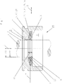
- FIG. 1 An embodiment of a sealing arrangement according to the invention is shown in a schematic representation.
- the seal assembly Figure 1 is used in a monotube shock absorber of a motor vehicle and comprises the first machine element 4, the second machine element 5 and the sealing ring 6, which seals the two spaces 2, 3 which are arranged adjacent to one another in the axial direction 1.
- the first machine element 4 is designed as a piston of the single-tube shock absorber 25, the second machine element 5 as a housing of the single-tube shock absorber 25, which surrounds the piston on the outer circumference.
- the piston is movable back and forth relative to the housing in the axial direction 1, the piston being enclosed by the housing at a radial distance.
- the sealing ring 6 is arranged in the gap 7 formed by the radial distance within the installation space 10.
- the sealing ring 6 comprises the dynamically stressed first sealing lip 8 and two further dynamically stressed sealing lips 20, 21, which are connected downstream of the first sealing lip 8 on the side axially facing away from the first space 2 to be sealed in a functional series connection.
- the sealing ring 6 is of circular design and comprises a first 11 and a second end face 12.
- the first end face 11 is the first space 2 to be sealed and the second end face 12 is the second space 3 to be sealed axially facing.
- the first space 2 forms the high-pressure space of the monotube shock absorber 25, the second space 3, in contrast, the low-pressure space.
- the second end face 12 of the sealing ring 6 is designed as a first contact surface 13, the first contact surface 13 abutting a second contact surface 14 which is part of the second machine element 5 and is arranged on the side of the second machine element 5 which faces the first contact surface 13.
- the contact surfaces 13 are each formed as an inclined plane 15, 16.
- the inner diameters of the sealing lips 8, 20, 21 are reduced radially towards one another in the direction of the surface 9 to be sealed by a displacement of the contact surfaces 13, 14.
- the contact surfaces 13, 14 shown here close with the imaginary radial plane 17, which cuts through the contact surfaces 13, 14 in the radial direction, in each case an angle ⁇ 1 , ⁇ 2 , which is 12 to 25 degrees.
- the first end face 11 is arranged axially opposite to the second end face 12 of the sealing ring 6 and extends in the radial direction 18 parallel to the imaginary radial plane 17. Due to the configuration of the end faces 11, 12 and the aforementioned angles of the contact surfaces 13, 14, the Sealing ring 6 has a greater thickness 19 radially on the inside in the axial direction 1 than on the outside circumference in the radial direction 18.
- the sealing ring 6 is made in one piece and of the same material and consists predominantly of an FKM material, which can optionally be filled with a wear-reducing and / or friction-reducing filler 24.
- the first machine element 4 moves analogously to the micro-vibrations relative to the second machine element 5 during the entire transport of the motor vehicle.
- the sealing lips 8, 20, 21 are insufficiently lubricated, in contrast to the intended use of the sealing arrangement, for example when the motor vehicle is driven on the road, the first machine element 4 axially differs from the second machine element 5 large amplitudes moved and thereby the sealing lips 8, 20, 21 are sufficiently lubricated.
- the sealing ring 6 is shown in its production-related state.
- the first machine element 4 to be sealed is shown invisibly in two-dot-dash lines.
- the first sealing lip 8 has an inner diameter that is smaller than the diameter of the surface 9 to be sealed of the first machine element 4. Due to this overlap, the first sealing lip 8 always surrounds the surface 9 to be sealed in a sealing manner under radial prestress.
- the diameter 22 of the sealing lip 20 arranged axially adjacent to the sealing lip 8 is the same or only very slightly smaller than the diameter of the surface to be sealed 9.
- the second sealing lip 20 encloses the surface 9 to be sealed without a differential pressure between the spaces 2, 3 with a very slight, if any, radial preload.
- the third sealing lip 21 has a larger diameter 23 than the surface 9 to be sealed, so that the third sealing lip 21 seals the surface 9 to be sealed only when there is a clear differential pressure between the spaces 2, 3 to be sealed, for example in the order of magnitude of 25 bar encloses.
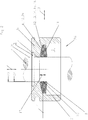
- Figure 2 is a section of the seal arrangement according to Figure 1 shown.
- the sealing arrangement is shown in the assembled state, the differential pressure between the rooms 2, 3 to be sealed being approximately 0 bar.
- the first sealing lip 8 surrounds the surface 9 to be sealed with a sufficiently large radial preload
- the second sealing lip 20 also surrounds the surface 9 to be sealed with a relatively lower radial preload
- the third sealing lip 21 surrounds the surface 9 to be sealed with a radial spacing; it does not touch the surface 9 to be sealed.
- Figure 3 is the excerpt from the Figures 1 and 2 shown, the differential pressure between the rooms to be sealed against each other 2, 3 is about 25 bar.
- the surface 9 to be sealed is sealingly enclosed by all three sealing lips 8, 20, 21 under radial prestressing, the radial prestressing of the first sealing lip 8 being greatest, the second sealing lip 20 being moderately large and the third sealing lip 21 being the smallest.
Description
Die Erfindung betrifft eine Dichtungsanordnung zur Abdichtung von zwei in axialer Richtung benachbart zueinander angeordneten und gegeneinander abzudichtenden Räumen, umfassend ein erstes Maschinenelement, ein zweites Maschinenelement und einen Dichtring, wobei das erste Maschinenelement vom zweiten Maschinenelement mit radialen Abstand umschlossen ist und wobei in dem durch den radialen Abstand gebildeten Spalt der Dichtring angeordnet ist, wobei der Dichtring zumindest eine dynamisch beanspruchte erste Dichtlippe aufweist, die eine abzudichtende Oberfläche des ersten Maschinenelements dichtend umschließt, wobei der Dichtring in einem Einbauraum des zweiten Maschinenelements angeordnet ist und wobei der Dichtring eine erste und eine zweite Stirnseite aufweist, von denen die erste Stirnseite dem abzudichtenden ersten Raum und die zweite Stirnseite dem abzudichtenden zweiten Raum axial zugewandt ist, wobei der erste Raum, bezogen auf den zweiten Raum, mit einem relativen Überdruck beaufschlagbar ist, wobei die zweite Stirnseite als erste Kontaktfläche des Dichtrings ausgebildet ist, wobei das zweite Maschinenelement auf der der ersten Kontaktfläche axial zugewandten Seite eine zweite Kontaktfläche aufweist und wobei sich die erste und die zweite Kontaktfläche anliegend berühren.The invention relates to a sealing arrangement for sealing two spaces which are arranged adjacent to one another in the axial direction and are to be sealed off from one another, comprising a first machine element, a second machine element and a sealing ring, the first machine element being enclosed by the second machine element at a radial distance, and in which the Radially spaced gap of the sealing ring is arranged, wherein the sealing ring has at least one dynamically stressed first sealing lip, which sealingly surrounds a surface to be sealed of the first machine element, wherein the sealing ring is arranged in an installation space of the second machine element and wherein the sealing ring has a first and a second Has end face, of which the first end face axially faces the first space to be sealed and the second end face faces the second space to be sealed, the first space, relative to the second space, with a relative overpressure b can be opened, the second end face being designed as the first contact surface of the sealing ring, the second machine element having a second contact surface on the side axially facing the first contact surface and the first and second contact surfaces touching one another.
Außerdem betrifft die Erfindung eine Verwendung einer solchen Dichtungsanordnung.The invention also relates to the use of such a sealing arrangement.
Eine solche Dichtungsanordnung ist aus der
Die vorbekannte Dichtungsanordnung umfasst eine Stangen- oder Kolbendichtung, die im Wesentlichen C-förmig und axial in Richtung des ersten abzudichtenden Raums offen ausgebildet ist. Abhängig vom relativen Überdruck im ersten Raum - bezogen auf den zweiten Raum - werden die Dichtlippen des Dichtrings in radialer Richtung mehr oder weniger stark aufgespreizt und legen sich mit entsprechender Vorspannung an die abzudichtenden Flächen der gegeneinander abzudichtenden Maschinenelemente an.The known sealing arrangement comprises a rod or piston seal, which is essentially C-shaped and is designed to be open axially in the direction of the first space to be sealed. Depending on the relative overpressure in the first room - in relation to the second room - the sealing lips of the sealing ring are more or less spread open in the radial direction and, with appropriate preload, they contact the surfaces of the machine elements to be sealed against each other.
Beide Dichtlippen sind dynamisch beansprucht. Eine Dichtlippe stützt sich an der Begrenzungswandung des Einbauraums des zweiten Maschinenelements dichtend ab, die andere dynamisch beanspruchte Dichtlippe demgegenüber auf der abzudichtenden Oberfläche des ersten Maschinenelements, das bezogen auf das zweite Maschinenelement in axialer Richtung translatorisch hin und her bewegbar ist.Both sealing lips are subject to dynamic loads. One sealing lip is sealingly supported on the boundary wall of the installation space of the second machine element, the other dynamically stressed sealing lip, on the other hand, on the surface of the first machine element to be sealed, which can be moved back and forth in the axial direction with respect to the second machine element.
Die einander zugewandten Kontaktflächen von Dichtring und Einbauraum erstrecken sich jeweils in radialer Richtung. Die radiale Anpressung der Dichtlippen an die jeweils abzudichtenden Oberflächen ist ausschließlich von der überdruckbedingten Aufspreizung der Dichtlippen abhängig. Im Bereich der Kontaktfläche des Dichtrings ist ein radial in Richtung des ersten Maschinenelements vorgewölbter Stützwulst angeordnet, der mit der axial gegenüberliegend angeordneten Dichtlippe durch einen bogenförmigen Abschnitt verbunden ist. Der bogenförmige Abschnitt umfasst zumindest zwei sich in Umfangsrichtung erstreckende, axial zueinander benachbarte Nuten, wobei zwischen den Nuten Stege angeordnet sind, die zusammen mit den Nuten Schmiermitteltaschen begrenzen.The mutually facing contact surfaces of the sealing ring and the installation space each extend in the radial direction. The radial pressure of the sealing lips on the surfaces to be sealed is solely dependent on the expansion of the sealing lips due to overpressure. In the area of the contact surface of the sealing ring there is a support bulge which is bulged radially in the direction of the first machine element and which is connected to the sealing lip arranged axially opposite by an arcuate section. The arcuate section comprises at least two grooves which extend in the circumferential direction and are axially adjacent to one another, webs are arranged between the grooves, which together with the grooves limit lubricant pockets.
Aus der
Aus der
Eine ähnliche Dichtungsanordnung wie zuvor beschrieben, ist aus der
Die konvergierenden Flanken bilden am Nutgrund des Einbauraums einen Drehpunkt, um den der Dichtungsring kippbar ist. Der Dichtungsring ist in seiner Ruhestellung mit einem vorbestimmten Spiel gegenüber der inneren Oberfläche des abzudichtenden Körpers eingebaut, so dass der Abstand zwischen dem Drehpunkt der Kippbewegung und den Punkten der Berührungslinie zwischen dem Dichtungsring und der Oberfläche unter dem Druck, der die Kippbewegung verursacht, größer ist als der größte Durchmesser des Dichtungsrings im Ruhezustand.The converging flanks form a fulcrum around the groove base of the installation space, around which the sealing ring can be tilted. The sealing ring is installed in its rest position with a predetermined play against the inner surface of the body to be sealed, so that the distance between the pivot point of the tilting movement and the points of contact line between the sealing ring and the surface is greater under the pressure which causes the tilting movement than the largest diameter of the seal ring at rest.
Aus der
Eine weitere Dichtungsanordnung ist aus der
Aus der
Aus der
Der Erfindung liegt die Aufgabe zu Grunde, eine Dichtungsanordnung der eingangs genannten Art derart weiter zu entwickeln, dass der Dichtring eine einfache Geometrie aufweist, einfach und kostengünstig herstellbar ist und dass der Dichtring auch ohne C-förmige Gestalt das erste Maschinenelement proportional zum relativen Überdruck im ersten Raum unter elastischer Vorspannung dichtend umschließt.The invention is based on the object of further developing a sealing arrangement of the type mentioned in such a way that the sealing ring has a simple geometry, is simple and inexpensive to produce and that the sealing ring encloses the first machine element in a sealing manner in proportion to the relative overpressure in the first space under elastic prestressing, even without a C-shaped configuration.
Diese Aufgabe wird erfindungsgemäß durch eine Dichtungsanordnung mit den Merkmalen von Anspruch 1 gelöst. Auf vorteilhafte Ausgestaltungen nehmen die auf Anspruch 1 rückbezogenen Ansprüche Bezug.This object is achieved according to the invention by a sealing arrangement with the features of claim 1. The claims referring back to claim 1 refer to advantageous embodiments.
Gelöst wird die Aufgabe dadurch, dass die erste und die zweite Kontaktfläche herstellungsbedingt kongruent zueinander ausgebildet sind, dass die Kontaktflächen jeweils als schiefe Ebene derart ausgebildet sind, dass bei Verlagerung des Dichtrings axial in Richtung des zweiten Raums gleichzeitig eine Relativbewegung der beiden Kontaktflächen aufeinander erfolgt und der Innendurchmesser der zumindest einen Dichtlippe die abzudichtende Oberfläche unter zunehmender radialer Vorspannung dichtend umschließt, wobei die Kontaktflächen mit einer gedachten Radialebene, die die Kontaktflächen durchschneidet, jeweils einen Winkel einschließen, der 5° bis 45° beträgt.The object is achieved in that the first and the second contact surface are congruent to each other due to the manufacturing process, that the contact surfaces are each designed as an inclined plane in such a way that when the sealing ring is displaced axially in the direction of the second space, the two contact surfaces move relative to one another and the inner diameter of the at least one sealing lip sealingly surrounds the surface to be sealed with increasing radial prestress, the contact surfaces with an imaginary radial plane which intersects the contact surfaces each enclosing an angle which is 5 ° to 45 °.
Hierbei ist von Vorteil, dass der Dichtring eine sehr einfache geometrische Gestalt aufweist, insbesondere nicht C-förmig ausgebildet ist und die abzudichtende Oberfläche des ersten Maschinenelements trotzdem mit einer variablen radialen Anpresskraft, abhängig von der Höhe des relativen Überdrucks im ersten Raum, dichtend umschließt.The advantage here is that the sealing ring has a very simple geometric shape, in particular is not C-shaped, and nevertheless seals the surface of the first machine element to be sealed with a variable radial contact pressure, depending on the level of the relative overpressure in the first space.
Die erste Dichtlippe umschließt die abzudichtende Oberfläche des ersten Maschinenelements in jedem Betriebszustand dichtend. Also auch dann, wenn zwischen den beiden abzudichtenden Räumen kein Differenzdruck besteht. In einem solchen Fall reicht die elastische Vorspannung in radialer Richtung, mit der die erste Dichtlippe die abzudichtende Oberfläche des ersten Maschinenelements aufgrund der Überdeckung zum ersten Maschinenelement dichtend umschließt, aus, um die beiden Räume zuverlässig gegeneinander abzudichten.The first sealing lip surrounds the surface of the first machine element to be sealed in any operating state. So even if there is no differential pressure between the two rooms to be sealed. In such a case, the elastic preload in the radial direction, with which the first sealing lip seals the surface of the first machine element to be sealed due to the overlap with the first machine element, is sufficient to reliably seal the two spaces from one another.
Steigt demgegenüber der Druck im ersten Raum, bezogen auf den Druck im zweiten Raum, wird der Dichtring axial in Richtung des zweiten Raums gedrückt. Die erste Kontaktfläche des Dichtrings, die als schiefe Ebene ausgebildet ist, wird an die zweite Kontaktfläche des Einbauraums verstärkt angedrückt, die ebenfalls als schiefe Ebene ausgebildet ist. Durch die Neigung von erster und zweiter Kontaktfläche ergibt sich bei Druckbeaufschlagung des Dichtrings aus dem abzudichtenden ersten Raum eine axiale Verlagerung des Dichtrings axial in Richtung des zweiten Raums und gleichzeitig eine Relativbewegung der beiden Kontaktflächen aufeinander, derart, dass mit steigendem Druck im ersten Raum und einer Bewegung der ersten Kontaktfläche auf der zweiten Kontaktfläche der Innendurchmesser des Dichtrings reduziert und dadurch die Dichtlippe verstärkt an die abzudichtende Oberfläche des ersten Maschinenelements angedrückt wird.On the other hand, if the pressure in the first space increases, based on the pressure in the second space, the sealing ring is pressed axially in the direction of the second space. The first contact surface of the sealing ring, which is designed as an inclined plane, is pressed more strongly onto the second contact surface of the installation space, which is likewise designed as an inclined plane. Due to the inclination of the first and second contact surfaces, when the sealing ring is pressurized from the first space to be sealed, there is an axial displacement of the sealing ring axially in the direction of the second space and at the same time a relative movement of the two contact surfaces to one another, such that with increasing pressure in the first space and one Movement of the first contact surface on the second contact surface reduces the inner diameter of the sealing ring and thereby the sealing lip is pressed against the surface of the first machine element to be sealed.
Die Stärke der radialen Vorspannung, mit der die erste Dichtlippe die abzudichtende Oberfläche des ersten Maschinenelements dichtend umschließt, korreliert also mit dem relativen Überdruck im abzudichtenden Raum.The strength of the radial preload with which the first sealing lip seals the surface of the first machine element to be sealed correlates with the relative overpressure in the space to be sealed.
Für die meisten Anwendungsfälle hat es sich als vorteilhaft bewährt, wenn die Kontaktflächen mit einer gedachten Radialebene, die die Kontaktflächen durchschneidet, jeweils einen Winkel einschließen, der 5° bis 45° beträgt.For most applications, it has proven to be advantageous if the contact surfaces with an imaginary radial plane that intersects the contact surfaces each enclose an angle that is 5 ° to 45 °.
Besonders vorteilhaft sind die Gebrauchseigenschaften, wenn die Winkel 10° bis 30° betragen. Durch die vergleichsweise kleinen Winkel baut die Dichtungsanordnung in axialer Richtung kompakt, und auch bei kleinen Wegen des Dichtrings axial in Richtung des niederdruckseitigen abzudichtenden zweiten Raums kann die radiale Vorspannung der Dichtlippe an der abzudichtenden Oberfläche des ersten Maschinenelements signifikant gesteigert werden.The properties of use are particularly advantageous if the angles are 10 ° to 30 °. Due to the comparatively small angle, the sealing arrangement is compact in the axial direction, and even with small paths of the sealing ring axially in the direction of the second space to be sealed on the low-pressure side, the radial preload of the sealing lip on the surface of the first machine element to be sealed can be significantly increased.
Die erste Stirnseite kann in radialer Richtung parallel zur gedachten Radialebene angeordnet sein. Die erste Stirnseite bildet die Fläche, an der der relative Überdruck aus dem ersten abzudichtenden Raum anliegt. Die erste Stirnseite ist kreisringförmig und in radialer Richtung im Wesentlichen glattflächig, ohne sprunghafte Richtungsänderungen, ausgebildet.The first end face can be arranged in the radial direction parallel to the imaginary radial plane. The first end face forms the surface on which the relative overpressure from the first space to be sealed is present. The first end face is circular and essentially has a smooth surface in the radial direction, without abrupt changes in direction.
Durch die zuvor beschriebenen Winkel ergibt sich in Verbindung mit der sich in radialer Richtung erstreckenden ersten Stirnseite eine Ausgestaltung, durch die der Dichtring eine in radialer Richtung zur ersten Dichtlippe hin zunehmende Dicke in axialer Richtung aufweist. Dadurch weist die Innenumfangsfläche des Dichtrings eine größere axiale Erstreckung auf, als die Außenumfangsfläche. Hierbei ist von Vorteil, dass die vergleichsweise große Erstreckung des Innenumfangs in axialer Richtung genutzt werden kann, um bedarfsweise zusätzlich zur ersten Dichtlippe weitere Dichtlippen vorzusehen, die der ersten Dichtlippe funktionstechnisch nachgeschaltet sind.The angles described above, in conjunction with the first end face extending in the radial direction, result in a configuration by which the sealing ring has a thickness in the axial direction that increases in the radial direction toward the first sealing lip. As a result, the inner circumferential surface of the sealing ring has a greater axial extent than the outer circumferential surface. It is advantageous here that the comparatively large extent of the inner circumference in the axial direction can be used to provide, in addition to the first sealing lip, additional sealing lips, if necessary, which functionally follow the first sealing lip.
Der ersten Dichtlippe kann axial auf der den Kontaktflächen zugewandten Seite zumindest eine dynamisch beanspruchte weitere Dichtlippe in einer funktionstechnischen Reihenschaltung axial benachbart zugeordnet sein. Eine solche funktionstechnische Reihenschaltung von Dichtlippen ist von Vorteil, um die Gebrauchseigenschaften der Dichtungsanordnung, insbesondere die Dichtwirkung bei hohen abzudichtenden Drücken, zu verbessern. Trotzdem sollen Reibleistung und Verschleiß der Dichtlippe möglichst minimal sein.The first sealing lip can be assigned axially on the side facing the contact surfaces at least one dynamically stressed further sealing lip in a functional series connection axially adjacent. Such a functional series connection of sealing lips is advantageous in order to improve the performance properties of the sealing arrangement, in particular the To improve the sealing effect at high pressures to be sealed. Nevertheless, the friction and wear of the sealing lip should be as minimal as possible.
Die weiteren Dichtlippen können, bezogen auf die erste Dichtlippe, bevorzugt einen größeren Durchmesser aufweisen, je weiter sie den Kontaktflächen in axialer Richtung angenähert sind. Durch eine solche Ausgestaltung ist die zuvor beschriebene Minimierung der Reibleistung und des Verschleißes der Dichtlippen möglich. Mit zunehmendem Druck im ersten Raum werden zusätzlich zur ersten Dichtlippe nacheinander die weiteren Dichtlippen mit dem ersten Maschinenelement dichtend in Berührung gebracht, abhängig von der Höhe des Drucks im ersten Raum.The further sealing lips can preferably have a larger diameter, based on the first sealing lip, the closer they are to the contact surfaces in the axial direction. Such a configuration enables the previously described minimization of the friction and wear of the sealing lips. With increasing pressure in the first space, in addition to the first sealing lip, the further sealing lips are brought into sealing contact with the first machine element, depending on the level of pressure in the first space.
Besteht zwischen den beiden gegeneinander abzudichtenden Räumen kein Differenzdruck oder nur ein sehr geringer Differenzdruck, zum Beispiel in Höhe von bis zu 5 bar, umschließt nur die erste Dichtlippe die abzudichtende Oberfläche des ersten Maschinenelements mit vergleichsweise geringer radialer Vorspannung dichtend.If there is no differential pressure between the two spaces to be sealed against one another or only a very low differential pressure, for example up to 5 bar, only the first sealing lip seals the surface of the first machine element to be sealed with a comparatively low radial preload.
Wird der Differenzdruck demgegenüber größer, legt sich, zum Beispiel bei einem Differenzdruck von etwa 15 bar, die der ersten Dichtlippe axial am nächsten benachbarte weitere Dichtlippe zusätzlich an die abzudichtende Oberfläche des ersten Maschinenelements dichtend an. Die radiale Vorspannung der ersten Dichtlippe ist dabei größer, als die radiale Vorspannung der weiteren Dichtlippe.If, on the other hand, the differential pressure becomes larger, the additional sealing lip axially closest to the first sealing lip, for example at a differential pressure of approximately 15 bar, also seals against the surface of the first machine element to be sealed. The radial preload of the first sealing lip is greater than the radial preload of the further sealing lip.
Wird der Differenzdruck weiter erhöht, beispielsweise auf 25 bar und mehr, umschließen alle Dichtlippen die abzudichtende Oberfläche des abzudichtenden Maschinenelements mit radialer Vorspannung dichtend, wobei auch in diesem Fall die radiale Vorspannung, mit der die erste Dichtlippe die abzudichtende Oberfläche des abzudichtenden ersten Maschinenelements dichtend umschließt am größten ist und die radiale Vorspannung der axial angrenzenden Dichtlippen mit zunehmendem axialen Abstand von der ersten Dichtlippe abnimmt.If the differential pressure is increased further, for example to 25 bar and more, all the sealing lips enclose the surface of the machine element to be sealed with radial preload, in this case also the radial preload with which the first sealing lip sealingly surrounds the surface of the first machine element to be sealed is greatest and the radial preload of the axially adjacent sealing lips decreases with increasing axial distance from the first sealing lip.
Dadurch ist die Geometrie des Dichtrings ausgezeichnet an die jeweiligen Gegebenheiten des Anwendungsfalles, insbesondere an die Höhe der abzudichtenden Drücke angepasst, wobei Reibleistung und Verschleiß dadurch minimiert und die Standzeiten des Dichtrings maximiert sind.As a result, the geometry of the sealing ring is excellently adapted to the particular circumstances of the application, in particular to the level of the pressures to be sealed, whereby friction and wear are minimized and the service life of the sealing ring is maximized.
Der Dichtring kann bevorzugt einstückig ausgebildet sein. Ein solcher Dichtring ist einfach und kostengünstig herstellbar. Auch die Montage des einstückigen Dichtrings ist denkbar einfach und die Gefahr von Montagefehlern ist auf ein Minimum begrenzt. Im Hinblick auf mehrteilige Dichtringe ist das von hervorzuhebendem Vorteil.The sealing ring can preferably be formed in one piece. Such a sealing ring is simple and inexpensive to manufacture. The one-piece sealing ring is also extremely easy to install and the risk of assembly errors is kept to a minimum. With regard to multi-part sealing rings, this is of particular advantage.
Der Dichtring ist bevorzugt materialeinheitlich ausgebildet. Zusätzlich zur einfachen und kostengünstigen Herstellbarkeit des Dichtrings ist von Vorteil, dass ein solcher Dichtring im Anschluss an seine Gebrauchsdauer sortenrein recycelt werden kann.The sealing ring is preferably made of the same material. In addition to the simple and inexpensive manufacture of the sealing ring, it is advantageous that such a sealing ring can be recycled according to type after its service life.
Der Werkstoff, aus dem der Dichtring hauptsächlich besteht, kann einen Füllstoff umfassen.The material from which the sealing ring mainly consists can comprise a filler.
Der Füllstoff ist bevorzugt verschleißreduzierend und/oder reibungsreduzierend ausgebildet. Durch eine solche Ausgestaltung weisen die zur Anwendung gelangenden Dichtlippen auch bei möglicherweise auftretender Mangelschmierung eine ausgezeichnete Haltbarkeit auf, so dass der Dichtring gleichbleibend gute Gebrauchseigenschaften während einer langen Gebrauchsdauer aufweist. Außerdem kann die Gleitfähigkeit der schiefen Ebenen von Dichtring und zweitem Maschinenelement aufeinander dadurch positiv beeinflusst werden.The filler is preferably designed to reduce wear and / or reduce friction. With such a configuration, the sealing lips used have an excellent durability even in the event of insufficient lubrication, so that the sealing ring has consistently good usage properties over a long service life. In addition, the slidability of the inclined planes between the sealing ring and the second machine element can be positively influenced.
Als vorteilhaft hat es sich bewährt, wenn der Dichtring zumindest hauptsächlich aus einem FKM-Werkstoff besteht. Der Dichtring weist dadurch eine gute Haltbarkeit während einer langen Gebrauchsdauer auf, ist in einem weiten Temperaturbereich einsetzbar und gegen die meisten abzudichtenden Medien resistent.It has proven to be advantageous if the sealing ring consists at least mainly of an FKM material. As a result, the sealing ring has good durability over a long period of use and is wide Temperature range applicable and resistant to most media to be sealed.
Außerdem betrifft die Erfindung die Verwendung einer Dichtungsanordnung, wie zuvor beschrieben, in einem Einrohr-Stoßdämpfer. Solche Einrohr-Stoßdämpfer gelangen zum Beispiel in Kraftfahrzeugen zur Anwendung und haben einen, im Vergleich zu Zweirohr-Stoßdämpfern, einfachen und teilearmen Aufbau und sind deshalb kostengünstig herstellbar.The invention also relates to the use of a sealing arrangement as described above in a single-tube shock absorber. Such single-tube shock absorbers are used, for example, in motor vehicles and, compared to two-tube shock absorbers, have a simple and low-part construction and are therefore inexpensive to produce.
In einem Einrohr-Stoßdämpfer ist der Dichtring innerhalb seines Einbauraums statisch vorgespannt, und zwar mit einem relativen Überdruck im abzudichtenden ersten Raum, der etwa 15 bar beträgt. Während der bestimmungsgemäßen Verwendung des Einrohr-Stoßdämpfers verändert sich der Differenzdruck, je nachdem ob der Einrohr-Stoßdämpfer in axialer Richtung gestaucht oder in axialer Richtung auseinander gezogen wird. Unabhängig von den Betriebsbedingungen ist im abzudichtenden ersten Raum jedoch stets ein statischer relativer Überdruck vorhanden.In a monotube shock absorber, the sealing ring is statically prestressed within its installation space, with a relative overpressure in the first space to be sealed, which is approximately 15 bar. During the intended use of the single-tube shock absorber, the differential pressure changes depending on whether the single-tube shock absorber is compressed in the axial direction or pulled apart in the axial direction. Regardless of the operating conditions, there is always a static relative overpressure in the first room to be sealed.
Die erfindungsgemäße Dichtungsanordnung wird nachfolgend anhand der
Die
-
Figur 1 ein Ausführungsbeispiel der erfindungsgemäßen Dichtungsanordnung im zusammengebauten Zustand, wobei der Dichtring in herstellungsbedingten Zustand dargestellt ist, -
Figur 2Figur 1 im eingebauten Zustand, ohne Differenzdruckbeaufschlagung, -
Figur 3 den Dichtring ausFigur 1 undFigur 2 im eingebauten Zustand, wobei der am Dichtring anliegende Differenzdruck etwa 25 bar beträgt.
-
Figure 1 an embodiment of the sealing arrangement according to the invention in the assembled state, the sealing ring being shown in the production-related state, -
Figure 2 the sealing ringFigure 1 when installed, without applying differential pressure, -
Figure 3 the sealing ringFigure 1 andFigure 2 in the installed state, the differential pressure applied to the sealing ring being approximately 25 bar.
In
Die Dichtungsanordnung aus
Das erste Maschinenelement 4 ist als Kolben des Einrohr-Stoßdämpfers 25 ausgebildet, das zweite Maschinenelement 5 als Gehäuse des Einrohr-Stoßdämpfers 25, das den Kolben außenumfangsseitig umschließt. Der Kolben ist relativ zum Gehäuse in axialer Richtung 1 hin und her beweglich, wobei der Kolben vom Gehäuse mit radialem Abstand umschlossen ist. Der Dichtring 6 ist in dem durch den radialen Abstand gebildeten Spalt 7 innerhalb des Einbauraums 10 angeordnet. Der Dichtring 6 umfasst die dynamisch beanspruchte erste Dichtlippe 8 sowie zwei weitere dynamisch beanspruchte Dichtlippen 20, 21, die der ersten Dichtlippe 8 auf der dem ersten abzudichtenden Raum 2 axial abgewandten Seite in einer funktionstechnischen Reihenschaltung nachgeschaltet sind.The first machine element 4 is designed as a piston of the single-
Der Dichtring 6 ist kreisringförmig ausgebildet und umfasst eine erste 11 und eine zweite Stirnseite 12. Die erste Stirnseite 11 ist dem abzudichtenden ersten Raum 2 und die zweite Stirnseite 12 dem abzudichtenden zweiten Raum 3 axial zugewandt. Der erste Raum 2 bildet den Hochdruckraum des Einrohr-Stoßdämpfers 25 der zweite Raum 3 demgegenüber den Niederdruckraum.The sealing ring 6 is of circular design and comprises a first 11 and a second end face 12. The
Die zweite Stirnseite 12 des Dichtrings 6 ist als erste Kontaktfläche 13 ausgebildet, wobei die erste Kontaktfläche 13 eine zweite Kontaktfläche 14 anliegend berührt, die Bestandteil des zweiten Maschinenelements 5 ist und auf der der ersten Kontaktfläche 13 axial zugewandten Seite des zweiten Maschinenelements 5 angeordnet ist.The second end face 12 of the sealing ring 6 is designed as a first contact surface 13, the first contact surface 13 abutting a second contact surface 14 which is part of the second machine element 5 and is arranged on the side of the second machine element 5 which faces the first contact surface 13.
Die Kontaktflächen 13 sind jeweils als schiefe Ebene 15, 16 ausgebildet. Bei Verlagerung des Dichtrings 6 axial in Richtung des niederdruckseitig angeordneten zweiten Raums 3 werden die Innendurchmesser der Dichtlippen 8, 20, 21 durch eine Verschiebung der Kontaktflächen 13, 14 aufeinander radial in Richtung der abzudichtenden Oberfläche 9 verkleinert. Die hier gezeigten Kontaktflächen 13, 14 schließen mit der gedachten Radialebene 17, die die Kontaktflächen 13, 14 in radialer Richtung durchschneidet, jeweils einen Winkel α1, α2, der 12 bis 25 Grad beträgt.The contact surfaces 13 are each formed as an inclined plane 15, 16. When the sealing ring 6 is displaced axially in the direction of the second space 3 arranged on the low pressure side, the inner diameters of the sealing
Die erste Stirnseite 11 ist axial gegenüberliegend zur zweiten Stirnseite 12 des Dichtrings 6 angeordnet und erstreckt sich in radialer Richtung 18 parallel zu der gedachten Radialebene 17. Durch die Ausgestaltung der Stirnseiten 11, 12 und die zuvor genannten Winkel der Kontaktflächen 13, 14, weist der Dichtring 6 radial innenseitig eine größere Dicke 19 in axialer Richtung 1 auf, als in radialer Richtung 18 außenumfangsseitig.The
Der Dichtring 6 ist einstückig und materialeinheitlich ausgebildet und besteht überwiegend aus einem FKM-Werkstoff, der optional mit einem verschleißreduzierenden und/oder reibungsreduzierenden Füllstoff 24 gefüllt sein kann.The sealing ring 6 is made in one piece and of the same material and consists predominantly of an FKM material, which can optionally be filled with a wear-reducing and / or friction-reducing filler 24.
Das Vorsehen eines solchen Füllstoffs 24 ist insbesondere für die Haltbarkeit der Dichtlippen 8, 20, 21 vorteilhaft.The provision of such a filler 24 is particularly advantageous for the durability of the sealing
Beim Transport von Kraftfahrzeugen per LKW, Frachtschiff oder Bahn kann es zu sehr kleinamplitudigen Mikroschwingungen kommen, wobei sich das erste Maschinenelement 4 analog zu den Mikroschwingungen relativ zum zweiten Maschinenelement 5 während des gesamten Transports des Kraftfahrzeugs bewegt. Während des Transports des Kraftfahrzeugs werden die Dichtlippen 8, 20, 21 nur unzureichend geschmiert, im Gegensatz zur bestimmungsgemäßen Verwendung der Dichtungsanordnung, zum Beispiel dann, wenn das Kraftfahrzeug auf der Straße gefahren wird, sich das erste Maschinenelement 4 axial zum zweiten Maschinenelement 5 mit unterschiedlich großen Amplituden bewegt und dadurch die Dichtlippen 8, 20, 21 ausreichend gut geschmiert werden.When transporting motor vehicles by truck, cargo ship or train, very small-amplitude micro-vibrations can occur, the first machine element 4 moving analogously to the micro-vibrations relative to the second machine element 5 during the entire transport of the motor vehicle. During the transport of the motor vehicle, the sealing
Durch die verschleißreduzierenden und/oder reibungsreduzierenden Füllstoffe 24 tritt auch dann kein nachteiliger Verschleiß an den Dichtlippen 8, 20, 21 auf, wenn unter den Dichtlippen 8, 20, 21, zum Beispiel beim Transport wie zuvor beschrieben, Mangelschmierung herrscht.Due to the wear-reducing and / or friction-reducing fillers 24, there is no disadvantageous wear on the sealing
In
Der Dichtring 6 ist in seinem herstellungsbedingten Zustand gezeigt. Das abzudichtende erste Maschinenelement 4 ist unsichtbar strich-zwei-punktiert dargestellt.The sealing ring 6 is shown in its production-related state. The first machine element 4 to be sealed is shown invisibly in two-dot-dash lines.
Es ist zu erkennen, dass die erste Dichtlippe 8 einen Innendurchmesser aufweist, der kleiner als der Durchmesser der abzudichtenden Oberfläche 9 des ersten Maschinenelements 4 ist. Durch diese Überdeckung umschließt die erste Dichtlippe 8 die abzudichtende Oberfläche 9 stets unter radialer Vorspannung dichtend.It can be seen that the first sealing lip 8 has an inner diameter that is smaller than the diameter of the
Der Durchmesser 22 der axial zur Dichtlippe 8 benachbart angeordneten Dichtlippe 20 ist gleich oder nur ganz wenig kleiner, als der Durchmesser der abzudichtenden Oberfläche 9. Dadurch umschließt die zweite Dichtlippe 20 die abzudichtende Oberfläche 9 ohne Differenzdruck zwischen den Räumen 2, 3 mit einer, wenn überhaupt, nur sehr geringen radialen Vorspannung.The
Die dritte Dichtlippe 21 weist demgegenüber einen größeren Durchmesser 23 auf, als die abzudichtende Oberfläche 9, so dass die dritte Dichtlippe 21 die abzudichtende Oberfläche 9 nur bei deutlichem Differenzdruck zwischen den abzudichtenden Räumen 2, 3, zum Beispiel in der Größenordnung um 25 bar, dichtend umschließt.In contrast, the
In
In
Claims (12)
- Seal arrangement for sealing two spaces (2, 3) which are arranged adjacently with respect to one another in the axial direction (1) and are to be sealed with respect to one another, comprising a first machine element (4), a second machine element (5) and a sealing ring (6), the first machine element (4) being enclosed by the second machine element (5) at a radial spacing, and the sealing ring (6) being arranged in the gap (7) which is formed by way of the radial spacing, the sealing ring (6) having at least one dynamically loaded first sealing lip (8) which sealingly encloses a surface (9) to be sealed of the first machine element (4), the sealing ring (6) being arranged in an installation space (10) of the second machine element (5), and the sealing ring (6) having a first (11) and a second end side (12), of which the first end side (11) axially faces the first space (2) to be sealed and the second end side (12) axially faces the second space (3) to be sealed, it being possible for the first space (2) to be loaded with a relative positive pressure, in relation to the second space (3), the second end side (12) being configured as a first contact face (13) of the sealing ring (6), the second machine element (5) having a second contact face (14) on the side which axially faces the first contact face (13), and the first (13) and the second contact face (14) making contact with one another in a bearing manner, characterized in that the first (13) and the second contact face (14) are of congruent configuration with respect to one another in a production-induced manner, in that the contact faces (13, 14) are configured in each case as an oblique plane (15, 16) in such a way that, in the case of a movement of the sealing ring (6) axially in the direction of the second space (3), a relative movement of the two contact faces (13, 14) on one another takes place at the same time, and the internal diameter of the at least one sealing lip (8) sealingly encloses the surface (9) to be sealed with an increasing radial prestress, the contact faces (13, 14) in each case enclosing an angle (α1, α2) which is from 5° to 45° with an imaginary radial plane (17) which intersects the contact faces (13, 14).
- Seal arrangement according to Claim 1, characterized in that the angles (α1, α2) are in each case from 10° to 30°.
- Seal arrangement according to either of Claims 1 and 2, characterized in that the first end side (11) is arranged parallel to the imaginary radial plane (17) in the radial direction (18).
- Seal arrangement according to one of Claims 1 to 3, characterized in that the sealing ring (6) has a thickness (19) in the axial direction (1), which thickness (19) increases in the radial direction (18) towards the first sealing lip (8).
- Seal arrangement according to one of Claims 1 to 4, characterized in that, axially on the side which faces the contact faces (13, 14), the first sealing lip (8) is assigned at least one dynamically loaded further sealing lip (20, 21) in a manner which is adjacent axially in a series connection in functional terms.
- Seal arrangement according to Claim 5, characterized in that, in relation to the first sealing lip (8), the further sealing lips (20, 21) have a greater diameter (22, 23) the closer they approach the contact faces (13, 14) in the axial direction (1).
- Seal arrangement according to one of Claims 1 to 6, characterized in that the sealing ring (6) is configured in one piece.
- Seal arrangement according to one of Claims 1 to 7, characterized in that the sealing ring (6) is configured from one material.
- Seal arrangement according to one of Claims 1 to 7, characterized in that the material, of which the sealing ring (6) mainly consists, comprises a filler (24).
- Seal arrangement according to Claim 9, characterized in that the filler (24) is of wear-reducing and/or friction-reducing configuration.
- Seal arrangement according to one of Claims 1 to 10, characterized in that the sealing ring (6) consists at least mainly of an FKM material.
- Use of a seal arrangement according to one of Claims 1 to 11 in a monotube shock absorber (25).
Applications Claiming Priority (1)
| Application Number | Priority Date | Filing Date | Title |
|---|---|---|---|
| DE102016013638.3A DE102016013638B4 (en) | 2016-11-16 | 2016-11-16 | Sealing arrangement and its use |
Publications (2)
| Publication Number | Publication Date |
|---|---|
| EP3324083A1 EP3324083A1 (en) | 2018-05-23 |
| EP3324083B1 true EP3324083B1 (en) | 2020-01-01 |
Family
ID=60301882
Family Applications (1)
| Application Number | Title | Priority Date | Filing Date |
|---|---|---|---|
| EP17201009.2A Active EP3324083B1 (en) | 2016-11-16 | 2017-11-10 | Seal assembly and its use |
Country Status (3)
| Country | Link |
|---|---|
| US (1) | US10408351B2 (en) |
| EP (1) | EP3324083B1 (en) |
| DE (1) | DE102016013638B4 (en) |
Families Citing this family (1)
| Publication number | Priority date | Publication date | Assignee | Title |
|---|---|---|---|---|
| DE102020106646B3 (en) * | 2020-03-11 | 2020-11-26 | Carl Freudenberg Kg | Seal arrangement and its use |
Family Cites Families (15)
| Publication number | Priority date | Publication date | Assignee | Title |
|---|---|---|---|---|
| US3218087A (en) | 1962-07-09 | 1965-11-16 | Boeing Co | Foot seal |
| FR1438393A (en) * | 1965-03-29 | 1966-05-13 | Seal | |
| CH560340A5 (en) * | 1973-02-09 | 1975-03-27 | Occident Etablissements | |
| DE3703360C2 (en) * | 1987-02-04 | 1993-11-18 | Knorr Bremse Ag | Sealing arrangement with a sealing ring which can be inserted into an annular groove |
| DE3828692A1 (en) | 1988-08-24 | 1990-03-15 | Busak & Luyken Gmbh & Co | ARRANGEMENT FOR SEALING A FLOATING ROD |
| DE4104070A1 (en) | 1991-02-11 | 1992-08-13 | Teves Gmbh Alfred | Brake cylinder seal - has reduced brake ring contact area on piston |
| DE19728605C2 (en) | 1997-07-04 | 2000-03-02 | Freudenberg Carl Fa | Rod or piston seal |
| JP3702416B2 (en) * | 2000-03-16 | 2005-10-05 | 株式会社日立製作所 | Hydraulic buffer |
| DE10102161B4 (en) | 2001-01-19 | 2006-06-22 | Wobben, Aloys, Dipl.-Ing. | Annular seal |
| JP2003049887A (en) * | 2001-08-02 | 2003-02-21 | Showa Corp | Shaft seal part structure for hydraulic shock absorber and its assembling method |
| DE10151023C1 (en) * | 2001-10-16 | 2003-02-27 | Thyssen Krupp Bilstein Gmbh | Hydraulic shock absorber has welding done from outside with weld seam root sealed by built-in component |
| US6896110B2 (en) * | 2003-09-25 | 2005-05-24 | Tenneco Automotive Operating Company Inc. | Temperature compensated dual acting slip |
| KR20120112490A (en) * | 2009-12-21 | 2012-10-11 | 아크티에볼라게트 에스케이에프 | Method and device of a sealing system |
| DE102011056692A1 (en) * | 2011-12-20 | 2013-06-20 | Parker Hannifin Manufacturing Germany GmbH & Co. KG | Seal with pressure relief function |
| ITTO20130548A1 (en) * | 2013-07-01 | 2015-01-02 | Skf Ab | LOW FRICTION SEALING COMPLEX FOR A WHEEL HUB UNIT AND WHEEL HUB UNIT EQUIPPED WITH THIS SEALING COMPLEX |
-
2016
- 2016-11-16 DE DE102016013638.3A patent/DE102016013638B4/en not_active Expired - Fee Related
-
2017
- 2017-11-10 EP EP17201009.2A patent/EP3324083B1/en active Active
- 2017-11-15 US US15/813,170 patent/US10408351B2/en active Active
Non-Patent Citations (1)
| Title |
|---|
| None * |
Also Published As
| Publication number | Publication date |
|---|---|
| US20180135758A1 (en) | 2018-05-17 |
| US10408351B2 (en) | 2019-09-10 |
| DE102016013638B4 (en) | 2019-05-02 |
| DE102016013638A1 (en) | 2018-05-17 |
| EP3324083A1 (en) | 2018-05-23 |
Similar Documents
| Publication | Publication Date | Title |
|---|---|---|
| EP2529134B1 (en) | Rotary seal arrangement | |
| EP2035732B1 (en) | Seal and seal arrangement | |
| EP2459906B1 (en) | Seal arrangement | |
| EP2027403B1 (en) | Seal assembly for relieving pressure | |
| DE2609446A1 (en) | BALL VALVE | |
| EP3625484B1 (en) | Rotary seal arrangement and rotary seal with return function | |
| EP1992849B1 (en) | Sealing arrangement | |
| EP0724693B1 (en) | Sealing device | |
| EP2963319B1 (en) | Gasket | |
| EP3324083B1 (en) | Seal assembly and its use | |
| EP0491771B1 (en) | Sealing arrangement | |
| DE102008024163B4 (en) | Composite pistons for a motor vehicle transmission | |
| EP3180550B1 (en) | Seal arrangement with damping element | |
| EP0573539B1 (en) | Sealing arrangement | |
| EP1611380A1 (en) | Sealing arrangement | |
| EP1184572B1 (en) | High pressure seal | |
| DE102008029642A1 (en) | Disk spring arrangement for use with e.g. static load, has spacer sections movable on contact surface during deformation of snap ring, where contact surface is arranged transverse to deformation direction | |
| DE102020106646B3 (en) | Seal arrangement and its use | |
| EP1687557B1 (en) | Connecting system | |
| WO2016169965A1 (en) | Piston-cylinder assembly for a piston compressor having a specific dynamically sealing piston ring | |
| DE102010052558A1 (en) | V-shaped packing ring for V-shaped packing sealing set used as e.g. rod seal for sealing piston rods in hydraulic application, has low pressure-side sealing surface including angle smaller than angle of high pressure-side sealing surface | |
| DE19610809A1 (en) | Sealing arrangement between piston and cylinder | |
| EP1878953A1 (en) | Sealing structure | |
| EP3511590B1 (en) | Seal and seal assembly comprising the seal | |
| DE102017003999B4 (en) | rod seal |
Legal Events
| Date | Code | Title | Description |
|---|---|---|---|
| PUAI | Public reference made under article 153(3) epc to a published international application that has entered the european phase |
Free format text: ORIGINAL CODE: 0009012 |
|
| STAA | Information on the status of an ep patent application or granted ep patent |
Free format text: STATUS: THE APPLICATION HAS BEEN PUBLISHED |
|
| AK | Designated contracting states |
Kind code of ref document: A1 Designated state(s): AL AT BE BG CH CY CZ DE DK EE ES FI FR GB GR HR HU IE IS IT LI LT LU LV MC MK MT NL NO PL PT RO RS SE SI SK SM TR |
|
| AX | Request for extension of the european patent |
Extension state: BA ME |
|
| STAA | Information on the status of an ep patent application or granted ep patent |
Free format text: STATUS: REQUEST FOR EXAMINATION WAS MADE |
|
| RIN1 | Information on inventor provided before grant (corrected) |
Inventor name: WADDELL, PAUL Inventor name: DIXON, ROSS Inventor name: WATLING, SIMON Inventor name: BILLANY, MATT Inventor name: EMIG, JUERGEN |
|
| 17P | Request for examination filed |
Effective date: 20180801 |
|
| RBV | Designated contracting states (corrected) |
Designated state(s): AL AT BE BG CH CY CZ DE DK EE ES FI FR GB GR HR HU IE IS IT LI LT LU LV MC MK MT NL NO PL PT RO RS SE SI SK SM TR |
|
| RIN1 | Information on inventor provided before grant (corrected) |
Inventor name: WATLING, SIMON Inventor name: DIXON, ROSS Inventor name: BILLANY, MATT Inventor name: EMIG, JUERGEN Inventor name: WADDELL, PAUL |
|
| RIC1 | Information provided on ipc code assigned before grant |
Ipc: F16J 15/16 20060101AFI20190725BHEP |
|
| GRAP | Despatch of communication of intention to grant a patent |
Free format text: ORIGINAL CODE: EPIDOSNIGR1 |
|
| STAA | Information on the status of an ep patent application or granted ep patent |
Free format text: STATUS: GRANT OF PATENT IS INTENDED |
|
| INTG | Intention to grant announced |
Effective date: 20190904 |
|
| GRAS | Grant fee paid |
Free format text: ORIGINAL CODE: EPIDOSNIGR3 |
|
| GRAA | (expected) grant |
Free format text: ORIGINAL CODE: 0009210 |
|
| STAA | Information on the status of an ep patent application or granted ep patent |
Free format text: STATUS: THE PATENT HAS BEEN GRANTED |
|
| AK | Designated contracting states |
Kind code of ref document: B1 Designated state(s): AL AT BE BG CH CY CZ DE DK EE ES FI FR GB GR HR HU IE IS IT LI LT LU LV MC MK MT NL NO PL PT RO RS SE SI SK SM TR |
|
| REG | Reference to a national code |
Ref country code: GB Ref legal event code: FG4D Free format text: NOT ENGLISH |
|
| REG | Reference to a national code |
Ref country code: CH Ref legal event code: EP Ref country code: AT Ref legal event code: REF Ref document number: 1220173 Country of ref document: AT Kind code of ref document: T Effective date: 20200115 |
|
| REG | Reference to a national code |
Ref country code: IE Ref legal event code: FG4D Free format text: LANGUAGE OF EP DOCUMENT: GERMAN |
|
| REG | Reference to a national code |
Ref country code: DE Ref legal event code: R096 Ref document number: 502017003342 Country of ref document: DE |
|
| REG | Reference to a national code |
Ref country code: NL Ref legal event code: MP Effective date: 20200101 |
|
| REG | Reference to a national code |
Ref country code: LT Ref legal event code: MG4D |
|
| PG25 | Lapsed in a contracting state [announced via postgrant information from national office to epo] |
Ref country code: LT Free format text: LAPSE BECAUSE OF FAILURE TO SUBMIT A TRANSLATION OF THE DESCRIPTION OR TO PAY THE FEE WITHIN THE PRESCRIBED TIME-LIMIT Effective date: 20200101 Ref country code: PT Free format text: LAPSE BECAUSE OF FAILURE TO SUBMIT A TRANSLATION OF THE DESCRIPTION OR TO PAY THE FEE WITHIN THE PRESCRIBED TIME-LIMIT Effective date: 20200527 Ref country code: NL Free format text: LAPSE BECAUSE OF FAILURE TO SUBMIT A TRANSLATION OF THE DESCRIPTION OR TO PAY THE FEE WITHIN THE PRESCRIBED TIME-LIMIT Effective date: 20200101 Ref country code: CZ Free format text: LAPSE BECAUSE OF FAILURE TO SUBMIT A TRANSLATION OF THE DESCRIPTION OR TO PAY THE FEE WITHIN THE PRESCRIBED TIME-LIMIT Effective date: 20200101 Ref country code: FI Free format text: LAPSE BECAUSE OF FAILURE TO SUBMIT A TRANSLATION OF THE DESCRIPTION OR TO PAY THE FEE WITHIN THE PRESCRIBED TIME-LIMIT Effective date: 20200101 Ref country code: NO Free format text: LAPSE BECAUSE OF FAILURE TO SUBMIT A TRANSLATION OF THE DESCRIPTION OR TO PAY THE FEE WITHIN THE PRESCRIBED TIME-LIMIT Effective date: 20200401 Ref country code: RS Free format text: LAPSE BECAUSE OF FAILURE TO SUBMIT A TRANSLATION OF THE DESCRIPTION OR TO PAY THE FEE WITHIN THE PRESCRIBED TIME-LIMIT Effective date: 20200101 |
|
| PG25 | Lapsed in a contracting state [announced via postgrant information from national office to epo] |
Ref country code: HR Free format text: LAPSE BECAUSE OF FAILURE TO SUBMIT A TRANSLATION OF THE DESCRIPTION OR TO PAY THE FEE WITHIN THE PRESCRIBED TIME-LIMIT Effective date: 20200101 Ref country code: BG Free format text: LAPSE BECAUSE OF FAILURE TO SUBMIT A TRANSLATION OF THE DESCRIPTION OR TO PAY THE FEE WITHIN THE PRESCRIBED TIME-LIMIT Effective date: 20200401 Ref country code: GR Free format text: LAPSE BECAUSE OF FAILURE TO SUBMIT A TRANSLATION OF THE DESCRIPTION OR TO PAY THE FEE WITHIN THE PRESCRIBED TIME-LIMIT Effective date: 20200402 Ref country code: IS Free format text: LAPSE BECAUSE OF FAILURE TO SUBMIT A TRANSLATION OF THE DESCRIPTION OR TO PAY THE FEE WITHIN THE PRESCRIBED TIME-LIMIT Effective date: 20200501 Ref country code: SE Free format text: LAPSE BECAUSE OF FAILURE TO SUBMIT A TRANSLATION OF THE DESCRIPTION OR TO PAY THE FEE WITHIN THE PRESCRIBED TIME-LIMIT Effective date: 20200101 Ref country code: LV Free format text: LAPSE BECAUSE OF FAILURE TO SUBMIT A TRANSLATION OF THE DESCRIPTION OR TO PAY THE FEE WITHIN THE PRESCRIBED TIME-LIMIT Effective date: 20200101 |
|
| REG | Reference to a national code |
Ref country code: DE Ref legal event code: R097 Ref document number: 502017003342 Country of ref document: DE |
|
| PG25 | Lapsed in a contracting state [announced via postgrant information from national office to epo] |
Ref country code: EE Free format text: LAPSE BECAUSE OF FAILURE TO SUBMIT A TRANSLATION OF THE DESCRIPTION OR TO PAY THE FEE WITHIN THE PRESCRIBED TIME-LIMIT Effective date: 20200101 Ref country code: SM Free format text: LAPSE BECAUSE OF FAILURE TO SUBMIT A TRANSLATION OF THE DESCRIPTION OR TO PAY THE FEE WITHIN THE PRESCRIBED TIME-LIMIT Effective date: 20200101 Ref country code: DK Free format text: LAPSE BECAUSE OF FAILURE TO SUBMIT A TRANSLATION OF THE DESCRIPTION OR TO PAY THE FEE WITHIN THE PRESCRIBED TIME-LIMIT Effective date: 20200101 Ref country code: RO Free format text: LAPSE BECAUSE OF FAILURE TO SUBMIT A TRANSLATION OF THE DESCRIPTION OR TO PAY THE FEE WITHIN THE PRESCRIBED TIME-LIMIT Effective date: 20200101 Ref country code: ES Free format text: LAPSE BECAUSE OF FAILURE TO SUBMIT A TRANSLATION OF THE DESCRIPTION OR TO PAY THE FEE WITHIN THE PRESCRIBED TIME-LIMIT Effective date: 20200101 Ref country code: SK Free format text: LAPSE BECAUSE OF FAILURE TO SUBMIT A TRANSLATION OF THE DESCRIPTION OR TO PAY THE FEE WITHIN THE PRESCRIBED TIME-LIMIT Effective date: 20200101 |
|
| PLBE | No opposition filed within time limit |
Free format text: ORIGINAL CODE: 0009261 |
|
| STAA | Information on the status of an ep patent application or granted ep patent |
Free format text: STATUS: NO OPPOSITION FILED WITHIN TIME LIMIT |
|
| 26N | No opposition filed |
Effective date: 20201002 |
|
| PG25 | Lapsed in a contracting state [announced via postgrant information from national office to epo] |
Ref country code: IT Free format text: LAPSE BECAUSE OF FAILURE TO SUBMIT A TRANSLATION OF THE DESCRIPTION OR TO PAY THE FEE WITHIN THE PRESCRIBED TIME-LIMIT Effective date: 20200101 |
|
| PG25 | Lapsed in a contracting state [announced via postgrant information from national office to epo] |
Ref country code: SI Free format text: LAPSE BECAUSE OF FAILURE TO SUBMIT A TRANSLATION OF THE DESCRIPTION OR TO PAY THE FEE WITHIN THE PRESCRIBED TIME-LIMIT Effective date: 20200101 Ref country code: PL Free format text: LAPSE BECAUSE OF FAILURE TO SUBMIT A TRANSLATION OF THE DESCRIPTION OR TO PAY THE FEE WITHIN THE PRESCRIBED TIME-LIMIT Effective date: 20200101 |
|
| PG25 | Lapsed in a contracting state [announced via postgrant information from national office to epo] |
Ref country code: MC Free format text: LAPSE BECAUSE OF FAILURE TO SUBMIT A TRANSLATION OF THE DESCRIPTION OR TO PAY THE FEE WITHIN THE PRESCRIBED TIME-LIMIT Effective date: 20200101 |
|
| REG | Reference to a national code |
Ref country code: CH Ref legal event code: PL |
|
| PG25 | Lapsed in a contracting state [announced via postgrant information from national office to epo] |
Ref country code: LU Free format text: LAPSE BECAUSE OF NON-PAYMENT OF DUE FEES Effective date: 20201110 |
|
| REG | Reference to a national code |
Ref country code: BE Ref legal event code: MM Effective date: 20201130 |
|
| PG25 | Lapsed in a contracting state [announced via postgrant information from national office to epo] |
Ref country code: CH Free format text: LAPSE BECAUSE OF NON-PAYMENT OF DUE FEES Effective date: 20201130 Ref country code: LI Free format text: LAPSE BECAUSE OF NON-PAYMENT OF DUE FEES Effective date: 20201130 |
|
| PG25 | Lapsed in a contracting state [announced via postgrant information from national office to epo] |
Ref country code: IE Free format text: LAPSE BECAUSE OF NON-PAYMENT OF DUE FEES Effective date: 20201110 Ref country code: FR Free format text: LAPSE BECAUSE OF NON-PAYMENT OF DUE FEES Effective date: 20201130 |
|
| PG25 | Lapsed in a contracting state [announced via postgrant information from national office to epo] |
Ref country code: TR Free format text: LAPSE BECAUSE OF FAILURE TO SUBMIT A TRANSLATION OF THE DESCRIPTION OR TO PAY THE FEE WITHIN THE PRESCRIBED TIME-LIMIT Effective date: 20200101 Ref country code: MT Free format text: LAPSE BECAUSE OF FAILURE TO SUBMIT A TRANSLATION OF THE DESCRIPTION OR TO PAY THE FEE WITHIN THE PRESCRIBED TIME-LIMIT Effective date: 20200101 Ref country code: CY Free format text: LAPSE BECAUSE OF FAILURE TO SUBMIT A TRANSLATION OF THE DESCRIPTION OR TO PAY THE FEE WITHIN THE PRESCRIBED TIME-LIMIT Effective date: 20200101 |
|
| PG25 | Lapsed in a contracting state [announced via postgrant information from national office to epo] |
Ref country code: MK Free format text: LAPSE BECAUSE OF FAILURE TO SUBMIT A TRANSLATION OF THE DESCRIPTION OR TO PAY THE FEE WITHIN THE PRESCRIBED TIME-LIMIT Effective date: 20200101 Ref country code: AL Free format text: LAPSE BECAUSE OF FAILURE TO SUBMIT A TRANSLATION OF THE DESCRIPTION OR TO PAY THE FEE WITHIN THE PRESCRIBED TIME-LIMIT Effective date: 20200101 |
|
| GBPC | Gb: european patent ceased through non-payment of renewal fee |
Effective date: 20211110 |
|
| PG25 | Lapsed in a contracting state [announced via postgrant information from national office to epo] |
Ref country code: BE Free format text: LAPSE BECAUSE OF NON-PAYMENT OF DUE FEES Effective date: 20201130 |
|
| PG25 | Lapsed in a contracting state [announced via postgrant information from national office to epo] |
Ref country code: GB Free format text: LAPSE BECAUSE OF NON-PAYMENT OF DUE FEES Effective date: 20211110 |
|
| REG | Reference to a national code |
Ref country code: AT Ref legal event code: MM01 Ref document number: 1220173 Country of ref document: AT Kind code of ref document: T Effective date: 20221110 |
|
| PG25 | Lapsed in a contracting state [announced via postgrant information from national office to epo] |
Ref country code: AT Free format text: LAPSE BECAUSE OF NON-PAYMENT OF DUE FEES Effective date: 20221110 |
|
| PGFP | Annual fee paid to national office [announced via postgrant information from national office to epo] |
Ref country code: DE Payment date: 20231121 Year of fee payment: 7 |