EP3625441B1 - Système de combustion à volume constant - Google Patents
Système de combustion à volume constant Download PDFInfo
- Publication number
- EP3625441B1 EP3625441B1 EP18729731.2A EP18729731A EP3625441B1 EP 3625441 B1 EP3625441 B1 EP 3625441B1 EP 18729731 A EP18729731 A EP 18729731A EP 3625441 B1 EP3625441 B1 EP 3625441B1
- Authority
- EP
- European Patent Office
- Prior art keywords
- chamber
- tongue
- combustion
- admission
- intake
- Prior art date
- Legal status (The legal status is an assumption and is not a legal conclusion. Google has not performed a legal analysis and makes no representation as to the accuracy of the status listed.)
- Active
Links
Images

Classifications
-
- F—MECHANICAL ENGINEERING; LIGHTING; HEATING; WEAPONS; BLASTING
- F23—COMBUSTION APPARATUS; COMBUSTION PROCESSES
- F23C—METHODS OR APPARATUS FOR COMBUSTION USING FLUID FUEL OR SOLID FUEL SUSPENDED IN A CARRIER GAS OR AIR
- F23C15/00—Apparatus in which combustion takes place in pulses influenced by acoustic resonance in a gas mass
-
- F—MECHANICAL ENGINEERING; LIGHTING; HEATING; WEAPONS; BLASTING
- F01—MACHINES OR ENGINES IN GENERAL; ENGINE PLANTS IN GENERAL; STEAM ENGINES
- F01L—CYCLICALLY OPERATING VALVES FOR MACHINES OR ENGINES
- F01L3/00—Lift-valve, i.e. cut-off apparatus with closure members having at least a component of their opening and closing motion perpendicular to the closing faces; Parts or accessories thereof
- F01L3/20—Shapes or constructions of valve members, not provided for in preceding subgroups of this group
- F01L3/205—Reed valves
-
- F—MECHANICAL ENGINEERING; LIGHTING; HEATING; WEAPONS; BLASTING
- F23—COMBUSTION APPARATUS; COMBUSTION PROCESSES
- F23R—GENERATING COMBUSTION PRODUCTS OF HIGH PRESSURE OR HIGH VELOCITY, e.g. GAS-TURBINE COMBUSTION CHAMBERS
- F23R7/00—Intermittent or explosive combustion chambers
-
- F—MECHANICAL ENGINEERING; LIGHTING; HEATING; WEAPONS; BLASTING
- F01—MACHINES OR ENGINES IN GENERAL; ENGINE PLANTS IN GENERAL; STEAM ENGINES
- F01L—CYCLICALLY OPERATING VALVES FOR MACHINES OR ENGINES
- F01L2301/00—Using particular materials
- F01L2301/02—Using ceramic materials
-
- F—MECHANICAL ENGINEERING; LIGHTING; HEATING; WEAPONS; BLASTING
- F02—COMBUSTION ENGINES; HOT-GAS OR COMBUSTION-PRODUCT ENGINE PLANTS
- F02C—GAS-TURBINE PLANTS; AIR INTAKES FOR JET-PROPULSION PLANTS; CONTROLLING FUEL SUPPLY IN AIR-BREATHING JET-PROPULSION PLANTS
- F02C5/00—Gas-turbine plants characterised by the working fluid being generated by intermittent combustion
- F02C5/02—Gas-turbine plants characterised by the working fluid being generated by intermittent combustion characterised by the arrangement of the combustion chamber in the chamber in the plant
-
- F—MECHANICAL ENGINEERING; LIGHTING; HEATING; WEAPONS; BLASTING
- F02—COMBUSTION ENGINES; HOT-GAS OR COMBUSTION-PRODUCT ENGINE PLANTS
- F02C—GAS-TURBINE PLANTS; AIR INTAKES FOR JET-PROPULSION PLANTS; CONTROLLING FUEL SUPPLY IN AIR-BREATHING JET-PROPULSION PLANTS
- F02C5/00—Gas-turbine plants characterised by the working fluid being generated by intermittent combustion
- F02C5/12—Gas-turbine plants characterised by the working fluid being generated by intermittent combustion the combustion chambers having inlet or outlet valves, e.g. Holzwarth gas-turbine plants
-
- F—MECHANICAL ENGINEERING; LIGHTING; HEATING; WEAPONS; BLASTING
- F02—COMBUSTION ENGINES; HOT-GAS OR COMBUSTION-PRODUCT ENGINE PLANTS
- F02K—JET-PROPULSION PLANTS
- F02K7/00—Plants in which the working fluid is used in a jet only, i.e. the plants not having a turbine or other engine driving a compressor or a ducted fan; Control thereof
- F02K7/02—Plants in which the working fluid is used in a jet only, i.e. the plants not having a turbine or other engine driving a compressor or a ducted fan; Control thereof the jet being intermittent, i.e. pulse-jet
- F02K7/06—Plants in which the working fluid is used in a jet only, i.e. the plants not having a turbine or other engine driving a compressor or a ducted fan; Control thereof the jet being intermittent, i.e. pulse-jet with combustion chambers having valves
-
- F—MECHANICAL ENGINEERING; LIGHTING; HEATING; WEAPONS; BLASTING
- F16—ENGINEERING ELEMENTS AND UNITS; GENERAL MEASURES FOR PRODUCING AND MAINTAINING EFFECTIVE FUNCTIONING OF MACHINES OR INSTALLATIONS; THERMAL INSULATION IN GENERAL
- F16K—VALVES; TAPS; COCKS; ACTUATING-FLOATS; DEVICES FOR VENTING OR AERATING
- F16K15/00—Check valves
- F16K15/14—Check valves with flexible valve members
- F16K15/16—Check valves with flexible valve members with tongue-shaped laminae
Definitions
- the invention relates to a constant volume combustion system comprising one or more combustion chambers, each being provided with at least one elastically deformable tab forming an air intake valve.
- a combustion chamber is supplied with pressurized air and comprises a fuel injector which is able to inject fuel into the air flow admitted in order to carry out combustion and thus cause the emission of hot gases. These hot gases can then be used to drive a turbine.
- the combustion chamber includes at least one intake port through which air is introduced into the interior of the chamber, and an exhaust port through which hot gases are vented outside of the chamber.
- Combustion chambers are in particular described in the document US 5,090,891 .
- the combustion chamber can operate on a Humphrey cycle, that is, a constant volume combustion cycle or "CVC".
- the constant volume combustion cycle comprises a combustion time (designated by the expression “combustion phase”), an exhaust time (designated by the expression “exhaust phase”), and an intake time.
- fresh air and flue gas scavenging referred to as the “scavenging phase”.
- the intake and exhaust ports are both closed.
- the intake port is closed and the exhaust port open.
- both intake and exhaust ports are open.
- the combustion chamber is thus commonly provided with an intake and exhaust mechanism making it possible to control the opening and closing of the intake and exhaust ports in order to ensure the completion of the three phases of the aforementioned cycle.
- a constant volume combustion system comprising at least one combustion chamber which comprises at least one intake port and one exhaust port, the system being characterized in that it comprises at least one elastically deformable tongue made of composite material with a ceramic matrix forming an air intake valve, the tongue being present inside the chamber and being positioned opposite the port of 'admission, the tongue comprising a first end fixed relatively to an internal wall of the chamber and a second free end opposite the first end, the second end being movable relative to the internal wall.
- the invention provides a simple solution for managing the admission of air into the combustion chamber by using the elastically deformable tongue, one end of which is fixed and the other end is free.
- the exhaust port is opened, which helps to reduce the pressure inside the chamber. The force applied to the tab is thus reduced, and the tab then moves away from the intake port. This release of the tab makes it possible to admit fresh air coming from the external environment and to carry out the sweeping phase.
- the elastically deformable tongue thus makes it possible to passively manage the air intake during the three phases of the combustion cycle at constant volume.
- This tab provides an air intake control mechanism that is simple, light and space-saving.
- the fact that the tongue is made of a ceramic matrix composite material (CMC material) allows it to perform its function despite the high temperatures and pressures encountered in operation in the combustion chamber.
- the first end of the tongue is fixed to the internal wall of the chamber.
- the tongue is defined by at least one slot formed in an air intake jacket positioned inside the chamber.
- the chamber comprises a plurality of intake ports, each of the intake ports facing a resiliently deformable tab.
- the chamber is delimited by a circumferential wall and the inlet ports are formed through this circumferential wall.
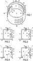
- the example shown in figures 1 to 5 relates to a combustion chamber in which the air intake valve is in the form a tongue 10 fixed, at one of its ends, to the internal wall 9a of the combustion chamber.
- the combustion chamber 1 comprises an enclosure 3 which delimits an interior volume V.
- the interior volume V is delimited and surrounded by the enclosure 3.
- the enclosure 3 here has a substantially cylindrical shape.
- the enclosure 3 can, more generally, have a symmetrical shape of revolution. Other shapes can however be envisaged for the enclosure 3, such as a parallelepiped shape, for example.
- the enclosure 3 comprises a circumferential wall 9 which is located around the interior volume V of the chamber 1.
- the enclosure 3 further comprises a first bottom 4 and a second bottom 6, shown in figures. figures 2 to 5 .
- the first bottom 4 and the second bottom 6 each delimit the interior volume V.
- the first bottom 4 and the second bottom 6 are located on either side of the circumferential wall 9.
- the combustion chamber 1 is provided with a fuel injector 13 placed here on the first base 4. Combustion can be initiated in a known manner either by a spark igniter (candle) or by a thermal gas igniter (not shown). ).
- the enclosure 3 defines a plurality of intake ports 5.
- the intake ports 5 are here provided through the circumferential wall 9.
- the admission of the fresh air takes place at different positions of the circumference of bedroom.
- This configuration improves the renewal of fresh air, increases turbulence and therefore combustion efficiency.
- Such a configuration also makes it possible to effectively cool the wall of the chamber by the fresh air admitted.
- the inlet port (s) 5 are positioned elsewhere than on the circumferential wall 9.
- the admission ports 5 can, as illustrated, be divided into several groups 5a, 5b and 5c of admission ports 5.
- Each group 5a, 5b and 5c can comprise a plurality of intake ports 5.
- each group 5a, 5b and 5c has eight intake ports 5 and the wall 5 has three groups 5a, 5b and 5c. .
- the groups 5a, 5b and 5c may or may not be regularly distributed over the circumferential wall 5.
- each tab 10 is positioned opposite several intake ports 5. More precisely, each group 5a, 5b and 5c of ports 5 is opposite a separate tab 10.
- the tongue 10 is made of CMC material, that is to say of a material comprising a fibrous reinforcement densified by a matrix at least partially made of ceramic.
- the enclosure 3 may itself also be made of CMC material or, as a variant, be of metallic material.
- the fibrous reinforcement can be made from carbon fibers (C) or from ceramic fibers, for example from silicon carbide (SiC) fibers.
- Fibers which can be used to constitute this fibrous reinforcement are produced by the Japanese company Nippon Carbon under the reference “Nicalon” or “Hi-Nicalon” or “Hi-Nicalon Type-S”, or by the Japanese company Ube Industries under the reference “Tyranno”. -ZMI ”.
- the carbon fibers which can be used are, for example, supplied under the name Torayca T300 3K by the company Toray.
- the fibers can be coated with a thin interphase layer of pyrolytic carbon (PyC), boron nitride (BN) or boron doped carbon (BC, with 5 at.% To 20 at.% Of B, the complement being C).
- the matrix at least partially made of ceramic.
- the matrix can be composed of more than 50% by mass of a ceramic material.
- the matrix can be made of a ceramic material.
- the matrix may include at least one phase of silicon carbide, for example.
- the matrix can be formed in a manner known per se by chemical vapor infiltration, or CVI (“Chemical Vapor Infiltration”).
- the matrix can also be at least partly formed by introducing powders, in particular carbon and possibly ceramic powders and infiltration with a metallic composition based on silicon in the molten state, to form a matrix of SiC-Si type.
- a metallic composition based on silicon in the molten state Such a process is well known and commonly referred to as the MI ("Melt Infiltration”) process.
- the tongue 10 is elastically deformable in order to close and reopen the intake ports 5 under the effect of the pressure variations encountered in operation in the chamber 1 as will be described below.
- the thin and slender shape of the tongue 10 can give it its elastically deformable character.
- the tongue 10 can thus have a length which is at least equal to three times its thickness. This length can be at least equal to five times the thickness, or even at least equal to ten times the thickness.
- the tongue 10 has a first end 12 which is fixed to an internal wall 9a of the enclosure 3.
- the first end 12 can for example be fixed by brazing to the internal wall 9a.
- the first end 12 is here fixed to the circumferential wall 9.
- the first end 12 is fixed relative to the internal wall 9a.
- the first end 12 is fixed in an area of the internal wall 9a which is devoid of an inlet port 5.
- the tongue 10 further comprises a free second end 14, distinct from the first end 12, which is movable relative to the wall. internal 9a.
- the tongue 10 comprises a middle part 11, located between the first 12 and second 14 ends, which is positioned opposite the intake ports 5.
- the tongue 10 can extend circumferentially around the interior volume V.
- the figure 2 illustrates chamber 1 at the start of combustion.
- the tongue 10 Before the start of combustion, the tongue 10 is in a position of equilibrium and is spaced from the inlet ports 5 by a non-zero spacing e.
- the interior volume V is in communication with the exterior E of the chamber 1 before initiation of combustion. This communication is provided by the intake ports 5.
- the exhaust port 7 is, for its part, closed by a shutter 17 before the start of combustion.
- the exhaust port 7 is here positioned at the level of the second bottom 6.
- the exhaust port could be positioned differently.
- An example has been illustrated where there is a single exhaust port 7. However, it does not depart from the scope of the invention when the chamber 1 is provided with several exhaust ports 7.
- Combustion is initiated by fuel injection (arrow C) and ignition.
- the initiation of combustion leads to increasing the pressure in the interior volume V.
- pressure is applied to the tab 10 (arrows P).
- a pressure threshold inside the interior volume V is reached, sufficient force is applied to the tongue 10 to press it against the intake ports 5 in order to close them.
- This configuration is shown in the figure 3 which schematizes the chamber during the continuation of combustion. In this case, the middle part 11 of the tongue 10, and possibly the second end 14, close off the intake ports 5. In this configuration, the interior volume V is not in communication with the exterior E.
- the exhaust port 7 is opened in order to evacuate the burnt gases outside the chamber 1.
- This phase corresponds to the exhaust phase illustrated on figure 4 where the flow of burnt gases leaving the chamber is shown by the arrow FA.
- the pressure in the interior volume V decreases, thus reducing the force applied to the tongue 10.
- the tongue 10 returns to its equilibrium position in which it is spaced from the intake ports (arrows R). .
- the invention makes it possible to achieve, in a passive manner, the sealing and re-opening of the intake port (s) 5.
- the use of this tongue constitutes a lightweight system. with soft contact which has good reactivity in opening and closing the intake ports.
- the figures 6 and 7 illustrate variants of tabs 20 and 31 which make it possible to manage the admission of air into the chamber on the same principle.
- the tabs 20 and 31 are, in these examples, defined by a slotted portion of an air intake jacket 18 and 30 which is positioned inside the chamber.
- the liner 18 is inserted inside the chamber 1.
- the liner 18 can be forcibly inserted into the chamber.
- the liner 18 can have a substantially constant thickness.
- the slits 22 are made by cutting the liner 18. The cutting can be done by laser or water jet cutting.
- the jacket 18 comprises a plurality of slots 22 which are distributed around the interior volume of the chamber.
- the sleeve 18 included a single slot 22.
- Each slot 22 here defines a plurality of tabs 20.
- the tabs 20 formed by the same slot 22 are here distributed along the height h from the room.
- the tongues 20 each comprise a first end 22 formed integrally with the sleeve 18 and which is fixed relative to the internal wall of the chamber.
- the tongues 20 further include a second free end 24 which is movable relative to the internal wall of the chamber.
- the tongues 20 here have an elongated shape along the circumference of the chamber.
- the slots 22 here each have a substantially sinusoidal shape (succession of hollows and bumps).
- the second end 24 of each tongue 20 being defined at a hollow or a bump.
- the circumferential wall 40 of the enclosure comprises a plurality of inlet ports 45 each located opposite a separate tab 20.
- Each tab 31 is defined between two adjacent slots 33.
- the slots 33 and the tabs 31 are distributed around the interior volume of the chamber.
- the second ends 34 of the tongues 31 may or may not be evenly distributed around the interior volume V.
- the first ends 32 of the tongues 31 are formed integrally with the liner 30.
- the intake ports 55 of the circumferential wall 50 of the enclosure are also positioned opposite the tabs 31.
- the slots 33 in this example have a bell shape.
- the combustion system which has just been described can be adapted to supplying gas to a turbomachine.
- the gases generated by the combustion system can be used to power a turbine, such as an aircraft engine turbine.
- the lightness of the valve system according to the invention makes this system particularly advantageous for boarding a vehicle such as an aircraft.
Landscapes
- Engineering & Computer Science (AREA)
- Mechanical Engineering (AREA)
- General Engineering & Computer Science (AREA)
- Chemical & Material Sciences (AREA)
- Combustion & Propulsion (AREA)
- Physics & Mathematics (AREA)
- Geometry (AREA)
- Portable Nailing Machines And Staplers (AREA)
- Cylinder Crankcases Of Internal Combustion Engines (AREA)
Description
- L'invention concerne un système de combustion à volume constant comprenant une ou plusieurs chambres de combustion, chacune étant munies d'au moins une languette élastiquement déformable formant clapet d'admission d'air.
- Une chambre de combustion est alimentée en air sous pression et comporte un injecteur de carburant qui est apte à injecter du carburant dans le flux d'air admis pour réaliser une combustion et provoquer ainsi l'émission de gaz chauds. Ces gaz chauds peuvent ensuite être utilisés pour entraîner une turbine. La chambre de combustion comprend au moins un port d'admission au travers duquel l'air est introduit à l'intérieur de la chambre, et un port d'échappement au travers duquel les gaz chauds sont évacués à l'extérieur de la chambre. Des chambres de combustion sont en particulier décrites dans le document
US 5 090 891 . - La chambre de combustion peut fonctionner selon un cycle de Humphrey, c'est-à-dire selon un cycle de combustion à volume constant ou « CVC ». Le cycle de combustion à volume constant comprend un temps de combustion (désigné par l'expression « phase de combustion »), un temps d'échappement (désigné par l'expression « phase d'échappement »), et un temps d'admission d'air frais et de balayage des gaz brûlés (désigné par l'expression « phase de balayage »). Durant la phase de combustion, les ports d'admission et d'échappement sont tous les deux fermés. Durant la phase d'échappement, le port d'admission est fermé et le port d'échappement ouvert. Lors de la phase de balayage, les ports d'admission et d'échappement sont tous les deux ouverts.
- La chambre de combustion est ainsi communément munie d'un mécanisme d'admission et d'échappement permettant de contrôler l'ouverture et la fermeture des ports d'admission et d'échappement afin d'assurer la réalisation des trois phases du cycle précitées.
- Il existe toutefois un besoin pour simplifier les mécanismes existants d'admission de l'air dans les chambres de combustion fonctionnant selon un cycle de combustion à volume constant.
- A cet effet, l'invention propose, selon un premier aspect, un système de combustion à volume constant comprenant au moins une chambre de combustion qui comporte au moins un port d'admission et un port d'échappement,
le système étant caractérisé en ce qu'il comprend au moins une languette élastiquement déformable en matériau composite à matrice céramique formant clapet d'admission d'air, la languette étant présente à l'intérieur de la chambre et étant positionnée en regard du port d'admission, la languette comprenant une première extrémité fixe relativement à une paroi interne de la chambre et une deuxième extrémité libre opposée à la première extrémité, la deuxième extrémité étant mobile relativement à la paroi interne. - L'invention propose une solution simple pour gérer l'admission de l'air dans la chambre de combustion grâce à l'emploi de la languette élastiquement déformable dont une extrémité est fixe et l'autre extrémité est libre. Durant la phase de combustion, il y a augmentation de la pression dans le volume intérieur, ce qui conduit à l'application d'une force suffisante sur la languette pour la plaquer contre le port d'admission afin de l'obturer. Une fois la phase de combustion achevée, le port d'échappement est ouvert, ce qui contribue à faire diminuer la pression à l'intérieur de la chambre. La force s'appliquant sur la languette est ainsi réduite, et la languette s'écarte alors du port d'admission. Ce dégagement de la languette permet d'admettre de l'air frais provenant du milieu extérieur et de réaliser la phase de balayage.
- La languette élastiquement déformable permet ainsi de gérer de manière passive l'admission de l'air durant les trois phases du cycle de combustion à volume constant. Cette languette constitue un mécanisme de contrôle de l'admission de l'air qui est simple, léger et peu encombrant. Le fait que la languette soit en matériau composite à matrice céramique (matériau CMC) lui permet d'assurer sa fonction malgré les hautes températures et pressions rencontrées en fonctionnement dans la chambre de combustion.
- Dans un exemple de réalisation, la première extrémité de la languette est fixée à la paroi interne de la chambre.
- Dans un exemple de réalisation, la languette est définie par au moins une fente ménagée dans une chemise d'admission d'air positionnée à l'intérieur de la chambre.
- Dans un exemple de réalisation, la chambre comprend une pluralité de ports d'admission, chacun des ports d'admission étant en regard d'une languette élastiquement déformable.
- Dans un exemple de réalisation, la chambre est délimitée par une paroi circonférentielle et les ports d'admission sont ménagés au travers de cette paroi circonférentielle.
- D'autres caractéristiques et avantages de l'invention ressortiront de la description suivante de modes particuliers de réalisation de l'invention, donnés à titre d'exemples non limitatifs, en référence aux dessins annexés, sur lesquels :
- la
figure 1 illustre, de manière schématique et partielle, une chambre de combustion utilisable dans le cadre de l'invention, - les
figures 2 à 5 sont des vues en coupe, schématiques et partielles, de la chambre de combustion de lafigure 1 durant les différentes phases du cycle de combustion à volume constant, - la
figure 6 illustre un premier exemple de chemise d'admission d'air et une enceinte de chambre de combustion associée utilisables dans le cadre de l'invention, et - la
figure 7 illustre un deuxième exemple de chemise d'admission d'air et une enceinte de chambre de combustion associée utilisables dans le cadre de l'invention. - L'exemple illustré aux
figures 1 à 5 concerne une chambre de combustion dans laquelle le clapet d'admission d'air est sous la forme d'une languette 10 fixée, à une de ses extrémités, à la paroi interne 9a de la chambre de combustion. - La chambre de combustion 1 comprend une enceinte 3 qui délimite un volume intérieur V. Le volume intérieur V est délimité et entouré par l'enceinte 3. L'enceinte 3 a ici une forme sensiblement cylindrique. L'enceinte 3 peut, plus généralement, avoir une forme symétrique de révolution. D'autres formes sont toutefois envisageables pour l'enceinte 3 comme une forme parallélépipédique, par exemple.
- L'enceinte 3 comprend une paroi circonférentielle 9 qui est située autour du volume intérieur V de la chambre 1. L'enceinte 3 comprend en outre un premier fond 4 et un deuxième fond 6, représentés aux
figures 2 à 5 . Le premier fond 4 et le deuxième fond 6 délimitent chacun le volume intérieur V. Le premier fond 4 et le deuxième fond 6 sont situés de part et d'autre de la paroi circonférentielle 9. - La chambre de combustion 1 est munie d'un injecteur 13 de carburant placé ici sur le premier fond 4. La combustion peut être initiée de façon connue soit par un allumeur à étincelle (bougie), soit par un allumeur thermique à gaz (non représentés).
- Dans l'exemple illustré, l'enceinte 3 définit une pluralité de ports d'admission 5. On ne sortirait toutefois pas du cadre de l'invention si la chambre comprenait un unique port d'admission. Les ports d'admission 5 sont ici ménagés au travers de la paroi circonférentielle 9. En positionnant ainsi les ports d'admission 5 autour du volume intérieur V, l'admission de l'air frais s'effectue à différentes positions de la circonférence de la chambre. Cette configuration améliore le renouvellement d'air frais, augmente les turbulences et donc l'efficacité de combustion. Une telle configuration permet en outre de refroidir efficacement la paroi de la chambre par l'air frais admis. On ne sort toutefois pas du cadre de l'invention si le ou les ports d'admission 5 sont positionnés ailleurs que sur la paroi circonférentielle 9.
- Les ports d'admission 5 peuvent, comme illustré, être répartis en plusieurs groupes 5a, 5b et 5c de ports 5 d'admission. Chaque groupe 5a, 5b et 5c peut comporter une pluralité de ports d'admission 5. Dans l'exemple illustré, chaque groupe 5a, 5b et 5c comporte huit ports d'admission 5 et la paroi 5 présente trois groupes 5a, 5b et 5c. Les groupes 5a, 5b et 5c peuvent ou non être régulièrement répartis sur la paroi circonférentielle 5.
- Dans cet exemple, chaque languette 10 est positionnée en regard de plusieurs ports d'admission 5. Plus précisément, chaque groupe 5a, 5b et 5c de ports 5 est en regard d'une languette 10 distincte.
- La languette 10 est en matériau CMC, c'est-à-dire en un matériau comprenant un renfort fibreux densifié par une matrice au moins partiellement en céramique. L'enceinte 3 peut elle aussi être en matériau CMC ou, en variante, être en matériau métallique.
- Dans un matériau CMC, le renfort fibreux peut être en fibres de carbone (C) ou en fibres de céramique, par exemple en fibres de carbure de silicium (SiC). Des fibres utilisables pour constituer ce renfort fibreux sont produites par la société japonaise Nippon Carbon sous la référence « Nicalon » ou « Hi-Nicalon » ou « Hi-Nicalon Type-S », ou par la société japonaise Ube Industries sous la référence « Tyranno-ZMI ». Les fibres de carbone utilisables sont, par exemple, fournies sous la dénomination Torayca T300 3K par la société Toray. Les fibres peuvent être revêtues d'une mince couche d'interphase en carbone pyrolytique (PyC), en nitrure de bore (BN) ou en carbone dopé au bore (BC, avec 5% at. à 20% at. de B, le complément étant C). Dans un matériau CMC, la matrice au moins partiellement en céramique. La matrice peut être composée à plus de 50% en masse par un matériau céramique. La matrice peut être constituée d'un matériau céramique. La matrice peut comporter au moins une phase de carbure de silicium, par exemple. La matrice peut être formée de manière connue en soi par infiltration chimique en phase gazeuse, ou CVI ("Chemical Vapor Infiltration"). La matrice peut aussi être au moins en partie formée par introduction de poudres, notamment poudres de carbone et éventuellement de céramique et infiltration par une composition métallique à base de silicium à l'état fondu, pour former une matrice de type SiC-Si. Un tel processus est bien connu et désigné couramment processus MI ("Melt Infiltration").
- La languette 10 est élastiquement déformable afin de réaliser l'obturation et la ré-ouverture des ports d'admission 5 sous l'effet des variations de pression rencontrées en fonctionnement dans la chambre 1 comme il sera décrit plus bas. La forme mince et élancée de la languette 10 peut lui conférer son caractère élastiquement déformable. La languette 10 peut ainsi présenter une longueur qui est au moins égale à trois fois son épaisseur. Cette longueur peut être au moins égale à cinq fois l'épaisseur, voire au moins égale à dix fois l'épaisseur. La languette 10 présente une première extrémité 12 qui est fixée à une paroi interne 9a de l'enceinte 3. La première extrémité 12 peut par exemple être fixée par brasage à la paroi interne 9a. La première extrémité 12 est ici fixée sur la paroi circonférentielle 9. La première extrémité 12 est fixe relativement à la paroi interne 9a. La première extrémité 12 est fixée dans une zone de la paroi interne 9a qui est dépourvue de port d'admission 5. La languette 10 comprend en outre une deuxième extrémité 14 libre, distincte de la première extrémité 12, qui est mobile relativement à la paroi interne 9a. La languette 10 comprend une partie médiane 11, située entre les première 12 et deuxième 14 extrémités, qui est positionnée en regard des ports d'admission 5. La languette 10 peut s'étendre de manière circonférentielle autour du volume intérieur V.
- La gestion de l'admission de l'air par la languette 10 va, à présent, être décrite en lien avec les
figures 2 à 5 . - La
figure 2 illustre la chambre 1 au début de la combustion. Avant le début de la combustion, la languette 10 est en position d'équilibre et est espacée des ports d'admission 5 d'un espacement e non nul. Ainsi, le volume intérieur V est en communication avec l'extérieur E de la chambre 1 avant initiation de la combustion. Cette communication est assurée par les ports d'admission 5. Le port d'échappement 7 est, quant à lui, obturé par un obturateur 17 avant le début de la combustion. Le port d'échappement 7 est ici positionné au niveau du deuxième fond 6. On pourrait positionner différemment le port d'échappement. On a illustré un exemple où il y a un unique port d'échappement 7. On ne sort toutefois pas du cadre de l'invention lorsque la chambre 1 est munie de plusieurs ports d'échappement 7. - La combustion est initiée par injection de carburant (flèche C) et allumage. L'initiation de la combustion conduit à faire augmenter la pression dans le volume intérieur V. De la sorte, une pression est appliquée sur la languette 10 (flèches P). Lorsqu'un seuil de pression à l'intérieur du volume intérieur V est atteint, une force suffisante est appliquée sur la languette 10 pour la plaquer contre les ports d'admission 5 afin de les obturer. Cette configuration est illustrée à la
figure 3 laquelle schématise la chambre durant la suite de la combustion. Dans ce cas, la partie médiane 11 de la languette 10, et éventuellement la deuxième extrémité 14, obturent les ports d'admission 5. Dans cette configuration, le volume intérieur V n'est pas en communication avec l'extérieur E. - Lorsque la combustion est terminée, le port d'échappement 7 est ouvert afin d'évacuer les gaz brûlés à l'extérieur de la chambre 1. Cette phase correspond à la phase d'échappement illustrée à la
figure 4 où le flux des gaz brûlés sortant de la chambre est matérialisé par la flèche FA. Durant la phase d'échappement, la pression dans le volume intérieur V diminue, diminuant ainsi la force appliquée sur la languette 10. La languette 10 revient dans sa position d'équilibre dans laquelle elle est espacée des ports d'admission (flèches R). - On obtient alors la configuration illustrée à la
figure 5 où les ports d'admission 5 et le port d'échappement 7 sont ouverts. Cette configuration permet la réalisation de la phase de balayage où il y a admission d'air frais et balayage des gaz brûlés (flèches FB). Après réalisation de cette étape de balayage, le port d'échappement 7 peut à nouveau être fermé puis une nouvelle étape de combustion peut être initiée comme décrit plus haut. - On notera donc que, grâce à la languette élastiquement déformable, l'invention permet de réaliser, de manière passive, l'obturation et la ré-ouverture du ou des ports d'admission 5. L'emploi de cette languette constitue un système léger avec contact souple qui présente une bonne réactivité d'ouverture et de fermeture des ports d'admission.
- Les
figures 6 et 7 illustrent des variantes de languettes 20 et 31 qui permettent de gérer l'admission d'air dans la chambre sur le même principe. Les languettes 20 et 31 sont, dans ces exemples, définies par une portion fendue d'une chemise d'admission d'air 18 et 30 laquelle est positionnée à l'intérieur de la chambre. - On a représenté à la
figure 6 un premier exemple de languettes 20 élastiquement déformables formées par des fentes 22 réalisées dans une chemise 18 d'admission d'air. La chemise 18 est insérée à l'intérieur de la chambre 1. La chemise 18 peut être insérée en force dans la chambre. La chemise 18 peut avoir une épaisseur sensiblement constante. Les fentes 22 sont réalisées par opération de découpe de la chemise 18. La découpe peut être effectuée par découpe au laser ou au jet d'eau. - Dans l'exemple illustré, la chemise 18 comprend une pluralité de fentes 22 qui sont réparties autour du volume intérieur de la chambre. On ne sortirait toutefois pas du cadre de l'invention si la chemise 18 comportait une unique fente 22. Chaque fente 22 définit ici une pluralité de languettes 20. Les languettes 20 formées par une même fente 22 sont ici réparties le long de la hauteur h de la chambre.
- Les languettes 20 comprennent chacune une première extrémité 22 formée d'un seul tenant avec la chemise 18 et qui est fixe relativement à la paroi interne de la chambre. Les languettes 20 comprennent en outre une deuxième extrémité 24 libre qui est mobile relativement à la paroi interne de la chambre. Les languettes 20 présentent ici une forme allongée le long de la circonférence de la chambre. Les fentes 22 présentent ici chacune une forme sensiblement sinusoïdale (succession de creux et de bosses). La deuxième extrémité 24 de chaque languette 20 étant définie au niveau d'un creux ou d'une bosse. La paroi circonférentielle 40 de l'enceinte comprend une pluralité de ports d'admission 45 chacun étant situé en face d'une languette 20 distincte.
- On a représenté à la
figure 7 un deuxième exemple de languettes 31 souples formées par des fentes 33 réalisées dans une chemise 30 d'admission d'air. Comme évoqué en lien avec lafigure 6 , la chemise d'admission d'air 18 est insérée, éventuellement en force, dans la chambre. - Chaque languette 31 est définie entre deux fentes 33 adjacentes. Les fentes 33 et les languettes 31 sont réparties autour du volume intérieur de la chambre. Les deuxièmes extrémités 34 des languettes 31 peuvent ou non être régulièrement réparties autour du volume intérieur V. Les premières extrémités 32 des languettes 31 sont formées d'un seul tenant avec la chemise 30. Les ports d'admission 55 de la paroi circonférentielle 50 de l'enceinte sont aussi positionnés en regard des languettes 31. Les fentes 33 ont dans cet exemple une forme en cloche.
- Le système de combustion qui vient d'être décrit peut être adapté à l'alimentation en gaz d'une turbomachine. Les gaz générés par le système de combustion peuvent permettre d'alimenter une turbine, comme une turbine de moteur d'aéronef. La légèreté du système à clapet selon l'invention rend ce système particulièrement avantageux pour un embarquement dans un véhicule comme un aéronef.
Claims (5)
- Système de combustion à volume constant comprenant au moins une chambre de combustion (1) qui comporte au moins un port d'admission (5 ; 45 ; 55) et un port d'échappement (7),
le système étant caractérisé en ce qu'il comprend au moins une languette élastiquement déformable (10 ; 20 ; 31) en matériau composite à matrice céramique formant clapet d'admission d'air, la languette étant présente à l'intérieur de la chambre et étant positionnée en regard du port d'admission, la languette comprenant une première extrémité (12 ; 22 ; 32) fixe relativement à une paroi interne (9a) de la chambre et une deuxième extrémité (14 ; 24 ; 34) libre opposée à la première extrémité, la deuxième extrémité étant mobile relativement à la paroi interne. - Système selon la revendication 1, dans lequel la première extrémité (12) de la languette (10) est fixée à la paroi interne (9a) de la chambre (1).
- Système selon la revendication 1, dans lequel la languette (20 ; 31) est définie par au moins une fente (23 ; 33) ménagée dans une chemise d'admission d'air (18 ; 30) positionnée à l'intérieur de la chambre.
- Système selon l'une quelconque des revendications 1 à 3, dans lequel la chambre (1) comprend une pluralité de ports d'admission (5 ; 45 ; 55), chacun des ports d'admission étant en regard d'une languette (10 ; 20 ; 31) élastiquement déformable.
- Système selon la revendication 4, dans lequel la chambre est délimitée par une paroi circonférentielle (9 ; 40 ; 50) et dans lequel les ports d'admission (5 ; 45 ; 55) sont ménagés au travers de cette paroi circonférentielle.
Applications Claiming Priority (2)
| Application Number | Priority Date | Filing Date | Title |
|---|---|---|---|
| FR1754286A FR3066548B1 (fr) | 2017-05-16 | 2017-05-16 | Systeme de combustion a volume constant |
| PCT/FR2018/051169 WO2018211209A1 (fr) | 2017-05-16 | 2018-05-15 | Systeme de combustion a volume constant |
Publications (2)
| Publication Number | Publication Date |
|---|---|
| EP3625441A1 EP3625441A1 (fr) | 2020-03-25 |
| EP3625441B1 true EP3625441B1 (fr) | 2021-04-21 |
Family
ID=59521046
Family Applications (1)
| Application Number | Title | Priority Date | Filing Date |
|---|---|---|---|
| EP18729731.2A Active EP3625441B1 (fr) | 2017-05-16 | 2018-05-15 | Système de combustion à volume constant |
Country Status (5)
| Country | Link |
|---|---|
| US (1) | US11619380B2 (fr) |
| EP (1) | EP3625441B1 (fr) |
| CN (1) | CN110546352B (fr) |
| FR (1) | FR3066548B1 (fr) |
| WO (1) | WO2018211209A1 (fr) |
Family Cites Families (10)
| Publication number | Priority date | Publication date | Assignee | Title |
|---|---|---|---|---|
| US3177663A (en) * | 1962-07-12 | 1965-04-13 | Robert B Black | Pulse jet engine |
| US5090891A (en) * | 1989-06-26 | 1992-02-25 | Indugas, Inc. | Hybrid combustion device and system therefor |
| JPH03227207A (ja) * | 1990-02-01 | 1991-10-08 | Suzuki Motor Corp | リードバルブ用弁体の製作方法 |
| EP0595384B1 (fr) * | 1992-10-26 | 1995-07-12 | General Motors Corporation | Clapet composite en polymère |
| US7631487B2 (en) * | 2006-10-27 | 2009-12-15 | Cfd Research Corporation | Constant volume rocket motor |
| US7536984B2 (en) | 2007-04-16 | 2009-05-26 | Lgd Technology, Llc | Variable valve actuator with a pneumatic booster |
| US8974891B2 (en) * | 2007-10-26 | 2015-03-10 | Coi Ceramics, Inc. | Thermal protection systems comprising flexible regions of inter-bonded lamina of ceramic matrix composite material and methods of forming the same |
| DE102010054206B4 (de) | 2010-12-11 | 2018-09-06 | Man Diesel & Turbo, Filial Af Man Diesel & Turbo Se, Tyskland | Zweitakt-Großdieselmotor, Auslassventil und Zylinderkopf dafür, sowie Herstellung, Betrieb und Verwendung eines Verbrennungsmotors |
| US9279503B2 (en) * | 2011-06-20 | 2016-03-08 | Streamline Automation, Llc | Constant volume combustion chamber |
| US8960148B2 (en) | 2012-07-11 | 2015-02-24 | George McGinnis | Heat transferring engine valve for fuel conservation |
-
2017
- 2017-05-16 FR FR1754286A patent/FR3066548B1/fr not_active Expired - Fee Related
-
2018
- 2018-05-15 EP EP18729731.2A patent/EP3625441B1/fr active Active
- 2018-05-15 WO PCT/FR2018/051169 patent/WO2018211209A1/fr not_active Ceased
- 2018-05-15 US US16/611,393 patent/US11619380B2/en active Active
- 2018-05-15 CN CN201880027903.5A patent/CN110546352B/zh active Active
Non-Patent Citations (1)
| Title |
|---|
| None * |
Also Published As
| Publication number | Publication date |
|---|---|
| US20200166207A1 (en) | 2020-05-28 |
| CN110546352B (zh) | 2020-10-30 |
| EP3625441A1 (fr) | 2020-03-25 |
| FR3066548A1 (fr) | 2018-11-23 |
| CN110546352A (zh) | 2019-12-06 |
| FR3066548B1 (fr) | 2019-07-12 |
| US11619380B2 (en) | 2023-04-04 |
| WO2018211209A1 (fr) | 2018-11-22 |
Similar Documents
| Publication | Publication Date | Title |
|---|---|---|
| EP2904329B1 (fr) | Injecteur a double circuit de chambre de combustion de turbomachine | |
| CA2531519C (fr) | Circuits de refroidissement pour anneau fixe de turbine a gaz | |
| WO2008139114A1 (fr) | Melangeur en cmc a capotage externe structural | |
| EP0248731A1 (fr) | Chambre de combustion pour turbomachines à orifices de mélange assurant le positionnement de la paroi chaude sur la paroi froide | |
| EP0499535B1 (fr) | Chambre de combustion pour turboréacteur à faible niveau d'émissions polluantes | |
| EP1911936B1 (fr) | Canal de transition entre deux étages de turbine | |
| FR2636376A1 (fr) | Dispositif de prelevement de gaz chauds dans une chambre de combustion et tete d'injection equipee d'un dispositif de prelevement | |
| EP3688294B1 (fr) | Chambre de combustion à volume constant et système de combustion pour turbomachine associé | |
| CA2886298C (fr) | Ensemble de combustion de turbomachine a variation d'alimentation d'air | |
| EP3625441B1 (fr) | Système de combustion à volume constant | |
| EP0301950B1 (fr) | Moteur à combustion interne suralimenté équipé d'une chambrede combustion auxiliaire | |
| EP0358655B1 (fr) | Procede et dispositif d'amenagement d'un moteur a deux temps a post-remplissage | |
| EP3974632B1 (fr) | Revêtement thermique pour un moteur à combustion interne à allumage commandé | |
| EP0014157A1 (fr) | Dispositif à deux chambres pour moteur à combustion interne | |
| EP3987165B1 (fr) | Système de combustion a volume constant avec injection synchronisée | |
| EP4658891A1 (fr) | Volet froid de tuyere d'arriere-corps | |
| FR3068076A1 (fr) | Systeme de combustion a volume constant avec flux de contournement | |
| FR2836180A1 (fr) | Moteur a combustion interne prevu pour produire un mouvement du type tumble dans le melange carbure et procede de commande du moteur | |
| BE558591A (fr) | ||
| BE533742A (fr) |
Legal Events
| Date | Code | Title | Description |
|---|---|---|---|
| STAA | Information on the status of an ep patent application or granted ep patent |
Free format text: STATUS: UNKNOWN |
|
| STAA | Information on the status of an ep patent application or granted ep patent |
Free format text: STATUS: THE INTERNATIONAL PUBLICATION HAS BEEN MADE |
|
| PUAI | Public reference made under article 153(3) epc to a published international application that has entered the european phase |
Free format text: ORIGINAL CODE: 0009012 |
|
| STAA | Information on the status of an ep patent application or granted ep patent |
Free format text: STATUS: REQUEST FOR EXAMINATION WAS MADE |
|
| 17P | Request for examination filed |
Effective date: 20191010 |
|
| AK | Designated contracting states |
Kind code of ref document: A1 Designated state(s): AL AT BE BG CH CY CZ DE DK EE ES FI FR GB GR HR HU IE IS IT LI LT LU LV MC MK MT NL NO PL PT RO RS SE SI SK SM TR |
|
| AX | Request for extension of the european patent |
Extension state: BA ME |
|
| DAV | Request for validation of the european patent (deleted) | ||
| DAX | Request for extension of the european patent (deleted) | ||
| REG | Reference to a national code |
Ref country code: DE Ref legal event code: R079 Ref document number: 602018015908 Country of ref document: DE Free format text: PREVIOUS MAIN CLASS: F01L0003200000 Ipc: F23R0007000000 |
|
| GRAP | Despatch of communication of intention to grant a patent |
Free format text: ORIGINAL CODE: EPIDOSNIGR1 |
|
| STAA | Information on the status of an ep patent application or granted ep patent |
Free format text: STATUS: GRANT OF PATENT IS INTENDED |
|
| INTG | Intention to grant announced |
Effective date: 20201120 |
|
| RIC1 | Information provided on ipc code assigned before grant |
Ipc: F23R 7/00 20060101AFI20201106BHEP |
|
| RIN1 | Information on inventor provided before grant (corrected) |
Inventor name: METGE, PIERRE JEAN-BAPTISTE Inventor name: LEYKO, MATTHIEU Inventor name: MECUSON, GAUTIER Inventor name: CONETE, ERIC |
|
| GRAS | Grant fee paid |
Free format text: ORIGINAL CODE: EPIDOSNIGR3 |
|
| GRAA | (expected) grant |
Free format text: ORIGINAL CODE: 0009210 |
|
| STAA | Information on the status of an ep patent application or granted ep patent |
Free format text: STATUS: THE PATENT HAS BEEN GRANTED |
|
| AK | Designated contracting states |
Kind code of ref document: B1 Designated state(s): AL AT BE BG CH CY CZ DE DK EE ES FI FR GB GR HR HU IE IS IT LI LT LU LV MC MK MT NL NO PL PT RO RS SE SI SK SM TR |
|
| REG | Reference to a national code |
Ref country code: GB Ref legal event code: FG4D Free format text: NOT ENGLISH |
|
| REG | Reference to a national code |
Ref country code: CH Ref legal event code: EP |
|
| REG | Reference to a national code |
Ref country code: DE Ref legal event code: R096 Ref document number: 602018015908 Country of ref document: DE Ref country code: IE Ref legal event code: FG4D Free format text: LANGUAGE OF EP DOCUMENT: FRENCH |
|
| REG | Reference to a national code |
Ref country code: AT Ref legal event code: REF Ref document number: 1385022 Country of ref document: AT Kind code of ref document: T Effective date: 20210515 |
|
| REG | Reference to a national code |
Ref country code: LT Ref legal event code: MG9D |
|
| REG | Reference to a national code |
Ref country code: AT Ref legal event code: MK05 Ref document number: 1385022 Country of ref document: AT Kind code of ref document: T Effective date: 20210421 |
|
| REG | Reference to a national code |
Ref country code: NL Ref legal event code: MP Effective date: 20210421 |
|
| PG25 | Lapsed in a contracting state [announced via postgrant information from national office to epo] |
Ref country code: FI Free format text: LAPSE BECAUSE OF FAILURE TO SUBMIT A TRANSLATION OF THE DESCRIPTION OR TO PAY THE FEE WITHIN THE PRESCRIBED TIME-LIMIT Effective date: 20210421 Ref country code: LT Free format text: LAPSE BECAUSE OF FAILURE TO SUBMIT A TRANSLATION OF THE DESCRIPTION OR TO PAY THE FEE WITHIN THE PRESCRIBED TIME-LIMIT Effective date: 20210421 Ref country code: HR Free format text: LAPSE BECAUSE OF FAILURE TO SUBMIT A TRANSLATION OF THE DESCRIPTION OR TO PAY THE FEE WITHIN THE PRESCRIBED TIME-LIMIT Effective date: 20210421 Ref country code: NL Free format text: LAPSE BECAUSE OF FAILURE TO SUBMIT A TRANSLATION OF THE DESCRIPTION OR TO PAY THE FEE WITHIN THE PRESCRIBED TIME-LIMIT Effective date: 20210421 Ref country code: AT Free format text: LAPSE BECAUSE OF FAILURE TO SUBMIT A TRANSLATION OF THE DESCRIPTION OR TO PAY THE FEE WITHIN THE PRESCRIBED TIME-LIMIT Effective date: 20210421 Ref country code: BG Free format text: LAPSE BECAUSE OF FAILURE TO SUBMIT A TRANSLATION OF THE DESCRIPTION OR TO PAY THE FEE WITHIN THE PRESCRIBED TIME-LIMIT Effective date: 20210721 |
|
| PG25 | Lapsed in a contracting state [announced via postgrant information from national office to epo] |
Ref country code: IS Free format text: LAPSE BECAUSE OF FAILURE TO SUBMIT A TRANSLATION OF THE DESCRIPTION OR TO PAY THE FEE WITHIN THE PRESCRIBED TIME-LIMIT Effective date: 20210821 Ref country code: GR Free format text: LAPSE BECAUSE OF FAILURE TO SUBMIT A TRANSLATION OF THE DESCRIPTION OR TO PAY THE FEE WITHIN THE PRESCRIBED TIME-LIMIT Effective date: 20210722 Ref country code: SE Free format text: LAPSE BECAUSE OF FAILURE TO SUBMIT A TRANSLATION OF THE DESCRIPTION OR TO PAY THE FEE WITHIN THE PRESCRIBED TIME-LIMIT Effective date: 20210421 Ref country code: RS Free format text: LAPSE BECAUSE OF FAILURE TO SUBMIT A TRANSLATION OF THE DESCRIPTION OR TO PAY THE FEE WITHIN THE PRESCRIBED TIME-LIMIT Effective date: 20210421 Ref country code: PT Free format text: LAPSE BECAUSE OF FAILURE TO SUBMIT A TRANSLATION OF THE DESCRIPTION OR TO PAY THE FEE WITHIN THE PRESCRIBED TIME-LIMIT Effective date: 20210823 Ref country code: PL Free format text: LAPSE BECAUSE OF FAILURE TO SUBMIT A TRANSLATION OF THE DESCRIPTION OR TO PAY THE FEE WITHIN THE PRESCRIBED TIME-LIMIT Effective date: 20210421 Ref country code: NO Free format text: LAPSE BECAUSE OF FAILURE TO SUBMIT A TRANSLATION OF THE DESCRIPTION OR TO PAY THE FEE WITHIN THE PRESCRIBED TIME-LIMIT Effective date: 20210721 Ref country code: LV Free format text: LAPSE BECAUSE OF FAILURE TO SUBMIT A TRANSLATION OF THE DESCRIPTION OR TO PAY THE FEE WITHIN THE PRESCRIBED TIME-LIMIT Effective date: 20210421 |
|
| REG | Reference to a national code |
Ref country code: CH Ref legal event code: PL |
|
| REG | Reference to a national code |
Ref country code: DE Ref legal event code: R097 Ref document number: 602018015908 Country of ref document: DE |
|
| PG25 | Lapsed in a contracting state [announced via postgrant information from national office to epo] |
Ref country code: EE Free format text: LAPSE BECAUSE OF FAILURE TO SUBMIT A TRANSLATION OF THE DESCRIPTION OR TO PAY THE FEE WITHIN THE PRESCRIBED TIME-LIMIT Effective date: 20210421 Ref country code: ES Free format text: LAPSE BECAUSE OF FAILURE TO SUBMIT A TRANSLATION OF THE DESCRIPTION OR TO PAY THE FEE WITHIN THE PRESCRIBED TIME-LIMIT Effective date: 20210421 Ref country code: SK Free format text: LAPSE BECAUSE OF FAILURE TO SUBMIT A TRANSLATION OF THE DESCRIPTION OR TO PAY THE FEE WITHIN THE PRESCRIBED TIME-LIMIT Effective date: 20210421 Ref country code: SM Free format text: LAPSE BECAUSE OF FAILURE TO SUBMIT A TRANSLATION OF THE DESCRIPTION OR TO PAY THE FEE WITHIN THE PRESCRIBED TIME-LIMIT Effective date: 20210421 Ref country code: RO Free format text: LAPSE BECAUSE OF FAILURE TO SUBMIT A TRANSLATION OF THE DESCRIPTION OR TO PAY THE FEE WITHIN THE PRESCRIBED TIME-LIMIT Effective date: 20210421 Ref country code: MC Free format text: LAPSE BECAUSE OF FAILURE TO SUBMIT A TRANSLATION OF THE DESCRIPTION OR TO PAY THE FEE WITHIN THE PRESCRIBED TIME-LIMIT Effective date: 20210421 Ref country code: LI Free format text: LAPSE BECAUSE OF NON-PAYMENT OF DUE FEES Effective date: 20210531 Ref country code: LU Free format text: LAPSE BECAUSE OF NON-PAYMENT OF DUE FEES Effective date: 20210515 Ref country code: CH Free format text: LAPSE BECAUSE OF NON-PAYMENT OF DUE FEES Effective date: 20210531 Ref country code: CZ Free format text: LAPSE BECAUSE OF FAILURE TO SUBMIT A TRANSLATION OF THE DESCRIPTION OR TO PAY THE FEE WITHIN THE PRESCRIBED TIME-LIMIT Effective date: 20210421 Ref country code: DK Free format text: LAPSE BECAUSE OF FAILURE TO SUBMIT A TRANSLATION OF THE DESCRIPTION OR TO PAY THE FEE WITHIN THE PRESCRIBED TIME-LIMIT Effective date: 20210421 |
|
| REG | Reference to a national code |
Ref country code: BE Ref legal event code: MM Effective date: 20210531 |
|
| PLBE | No opposition filed within time limit |
Free format text: ORIGINAL CODE: 0009261 |
|
| STAA | Information on the status of an ep patent application or granted ep patent |
Free format text: STATUS: NO OPPOSITION FILED WITHIN TIME LIMIT |
|
| 26N | No opposition filed |
Effective date: 20220124 |
|
| PG25 | Lapsed in a contracting state [announced via postgrant information from national office to epo] |
Ref country code: IE Free format text: LAPSE BECAUSE OF NON-PAYMENT OF DUE FEES Effective date: 20210515 |
|
| PG25 | Lapsed in a contracting state [announced via postgrant information from national office to epo] |
Ref country code: IS Free format text: LAPSE BECAUSE OF FAILURE TO SUBMIT A TRANSLATION OF THE DESCRIPTION OR TO PAY THE FEE WITHIN THE PRESCRIBED TIME-LIMIT Effective date: 20210821 Ref country code: AL Free format text: LAPSE BECAUSE OF FAILURE TO SUBMIT A TRANSLATION OF THE DESCRIPTION OR TO PAY THE FEE WITHIN THE PRESCRIBED TIME-LIMIT Effective date: 20210421 |
|
| PG25 | Lapsed in a contracting state [announced via postgrant information from national office to epo] |
Ref country code: IT Free format text: LAPSE BECAUSE OF FAILURE TO SUBMIT A TRANSLATION OF THE DESCRIPTION OR TO PAY THE FEE WITHIN THE PRESCRIBED TIME-LIMIT Effective date: 20210421 Ref country code: BE Free format text: LAPSE BECAUSE OF NON-PAYMENT OF DUE FEES Effective date: 20210531 |
|
| PG25 | Lapsed in a contracting state [announced via postgrant information from national office to epo] |
Ref country code: CY Free format text: LAPSE BECAUSE OF FAILURE TO SUBMIT A TRANSLATION OF THE DESCRIPTION OR TO PAY THE FEE WITHIN THE PRESCRIBED TIME-LIMIT Effective date: 20210421 |
|
| PG25 | Lapsed in a contracting state [announced via postgrant information from national office to epo] |
Ref country code: HU Free format text: LAPSE BECAUSE OF FAILURE TO SUBMIT A TRANSLATION OF THE DESCRIPTION OR TO PAY THE FEE WITHIN THE PRESCRIBED TIME-LIMIT; INVALID AB INITIO Effective date: 20180515 |
|
| PG25 | Lapsed in a contracting state [announced via postgrant information from national office to epo] |
Ref country code: MK Free format text: LAPSE BECAUSE OF FAILURE TO SUBMIT A TRANSLATION OF THE DESCRIPTION OR TO PAY THE FEE WITHIN THE PRESCRIBED TIME-LIMIT Effective date: 20210421 |
|
| PGFP | Annual fee paid to national office [announced via postgrant information from national office to epo] |
Ref country code: GB Payment date: 20240419 Year of fee payment: 7 |
|
| PGFP | Annual fee paid to national office [announced via postgrant information from national office to epo] |
Ref country code: DE Payment date: 20240418 Year of fee payment: 7 |
|
| PG25 | Lapsed in a contracting state [announced via postgrant information from national office to epo] |
Ref country code: MT Free format text: LAPSE BECAUSE OF FAILURE TO SUBMIT A TRANSLATION OF THE DESCRIPTION OR TO PAY THE FEE WITHIN THE PRESCRIBED TIME-LIMIT Effective date: 20210421 |
|
| PGFP | Annual fee paid to national office [announced via postgrant information from national office to epo] |
Ref country code: FR Payment date: 20250522 Year of fee payment: 8 |
|
| REG | Reference to a national code |
Ref country code: DE Ref legal event code: R119 Ref document number: 602018015908 Country of ref document: DE |
|
| PG25 | Lapsed in a contracting state [announced via postgrant information from national office to epo] |
Ref country code: TR Free format text: LAPSE BECAUSE OF FAILURE TO SUBMIT A TRANSLATION OF THE DESCRIPTION OR TO PAY THE FEE WITHIN THE PRESCRIBED TIME-LIMIT Effective date: 20210421 |
|
| GBPC | Gb: european patent ceased through non-payment of renewal fee |
Effective date: 20250515 |
|
| PG25 | Lapsed in a contracting state [announced via postgrant information from national office to epo] |
Ref country code: GB Free format text: LAPSE BECAUSE OF NON-PAYMENT OF DUE FEES Effective date: 20250515 |
|
| PG25 | Lapsed in a contracting state [announced via postgrant information from national office to epo] |
Ref country code: DE Free format text: LAPSE BECAUSE OF NON-PAYMENT OF DUE FEES Effective date: 20251202 |