EP3625436B1 - Cutter housing with inline mounting - Google Patents
Cutter housing with inline mounting Download PDFInfo
- Publication number
- EP3625436B1 EP3625436B1 EP18801376.7A EP18801376A EP3625436B1 EP 3625436 B1 EP3625436 B1 EP 3625436B1 EP 18801376 A EP18801376 A EP 18801376A EP 3625436 B1 EP3625436 B1 EP 3625436B1
- Authority
- EP
- European Patent Office
- Prior art keywords
- cutter
- wedge
- housing
- assembly
- spaced
- Prior art date
- Legal status (The legal status is an assumption and is not a legal conclusion. Google has not performed a legal analysis and makes no representation as to the accuracy of the status listed.)
- Active
Links
Images



Classifications
-
- E—FIXED CONSTRUCTIONS
- E21—EARTH OR ROCK DRILLING; MINING
- E21D—SHAFTS; TUNNELS; GALLERIES; LARGE UNDERGROUND CHAMBERS
- E21D9/00—Tunnels or galleries, with or without linings; Methods or apparatus for making thereof; Layout of tunnels or galleries
- E21D9/10—Making by using boring or cutting machines
- E21D9/1006—Making by using boring or cutting machines with rotary cutting tools
- E21D9/104—Cutting tool fixtures
Definitions
- a tunnel boring machine is a tunnel excavation apparatus for forming tunnels in a variety of soil and rock strata.
- a conventional TBM produces a smooth circular tunnel wall, with minimal collateral disturbance.
- a conventional TBM typically includes a full face rotatably driven cutter head that supports a plurality of cutter assemblies.
- a cutter head may have 20, 50, 100, or more cutter assemblies rotatably mounted to the cutter head.
- the cutter head In operation, the cutter head is urged against a surface to be bored such that at least some of the cutter assemblies forcibly engage the surface.
- a plurality of opposing sets of hydraulic cylinders engage the tunnel walls to anchor the TBM, and separate thrust cylinders press the cutter head against the rock or ground surface.
- the cutter head rotates about a longitudinal axis so that as the cutter assemblies are forcibly pressed against the surface they roll along the surface to fracture, loosen, grind, dislodge, and/or break materials from the surface.
- FIGURE 1 herein shows an exploded view of a conventional cutter ring assembly 10 housing for a tunnel boring machine.
- the cutter ring assembly 10 comprises a cutter ring 15 disposed on a hub 12 that is rotatably mounted on a shaft 13 for rotation about axis 14.
- Bearing assemblies (not shown) are mounted generally on the shaft 13 to provide for rotation of the hub 12 and cutter ring 15 about the shaft 13.
- the cutter housing assembly shown in FIGURE 1 comprises spaced-apart housing mounts 20L, 20R.
- the rotation axis 14 for the cutter ring 15 is generally perpendicular to the housing mounts 20L, 20R.
- Opposite ends of the shaft 13 are secured in the housing mounts 20L, 20R in L-shaped channels 21 that are sized to receive the cutter assembly shaft 13.
- the cutter assembly 10 is installed by positioning the opposite ends of the shaft 13 at the back of the housing mounts 20L, 20R to engage the long leg 21A of the L-shaped channels 21.
- the cutter assembly 10 is slid along the long leg 21A of the L-shaped channel 21 and then shifted laterally into the recess formed by the shorter leg 21B of the L-shaped channels 21.
- the cutter housing secures the cutter assembly 10 to the housing mounts 20L, 20R with a pair of wedge-lock assemblies 22A that engage respective ends of the shaft 13.
- the wedge-lock assemblies 22A each include a wedge 22, a clamp block 24, and an optional tubular sleeve 28 disposed there between.
- the wedge 22 is positioned to abut an angled face on the end of the shaft 13, and the clamp block 24 engages abutment surfaces 25 on the associated housing mount 20L, 20R.
- a bolt 23 extends through the wedge 22, the sleeve 28, and the clamp block 24, and is secured with two nuts 26 and a washer 27. As the bolt 23 is tensioned by torqueing the nuts 26 to a design specification, the wedge 22 locks the cutter assembly 10 in place.
- the housing mounts 20L, 20R are typically hard mounted onto the TBM, for example, by welding or the like.
- the housing mounts are therefore challenging to remove and replace if they become damaged. If a housing mount becomes damaged, it typically must be replaced in situ , which is particularly difficult and may shut down the TBM for an extended period of time.
- JP 2013 127182 A and US 2017/122105 A1 Further examples of a cutter assembly for a tunnel boring machine are shown in JP 2013 127182 A and US 2017/122105 A1 .
- the bridging supports 116 are generally T-shaped with a cutter ring mounting portion 117 that extends between and away from the housing mounts 120, and wedge-shaped end portions 118 that abut the corresponding abutment flange 122 of the housing mounts 120.
- the wedge-shaped end portions 118 of the bridging supports 116 define first wedge faces 119.
- Each elongate wedge portion 131 extends between and slidably engages the corresponding removable seat 140 and the bridging support end portions 118. It will be appreciated that the first wedge faces 119 of the end portions 118 and the second wedge face 139 of the wedge portion 131 are configured to slidably engage, such that urging the wedge member 130 towards the corresponding housing mount 120 (with attachment bolts 90) will produce clamping forces on the bridging support end portions 118.
- the wedge portion 131 is sized and configured such that very large clamping forces may be produced on the end portions 118 as the bolts 90 are tightened, resulting in a large preload on the wedge-shaped end portion 118.
- the magnitude of preload may be designed into the wedge members 130. For example, a larger preload may be achieved for a given bolt tension by providing a smaller wedge angle.
- the removable seats 140 in this embodiment are elongate members having a base portion 148 sized and shaped to slidably engage the transverse channel 128 of the corresponding housing mount 120.
- a plurality of spaced-apart seat portions 144 extend from the base portion 148, defining a plurality of channels 145 between the seat portions 144, and including channels 145 outboard of the seat portions 144.
- the seat portions 144 and channels 145 are configured to abut and extend the corresponding integral seat portions 124 and channels 125 in the corresponding housing mount 120 when the removable wedge seat 140 is installed in the housing mount 120.
Landscapes
- Engineering & Computer Science (AREA)
- Mining & Mineral Resources (AREA)
- Environmental & Geological Engineering (AREA)
- Life Sciences & Earth Sciences (AREA)
- General Life Sciences & Earth Sciences (AREA)
- Geochemistry & Mineralogy (AREA)
- Geology (AREA)
- Excavating Of Shafts Or Tunnels (AREA)
Description
- This application claims the benefit of
U.S. Provisional Patent Application No. 62/508,030, filed on May 18, 2017 - A tunnel boring machine ("TBM") is a tunnel excavation apparatus for forming tunnels in a variety of soil and rock strata. A conventional TBM produces a smooth circular tunnel wall, with minimal collateral disturbance. As discussed in
U.S. Patent No. 8,172,334, to Lindbergh et al. , a conventional TBM typically includes a full face rotatably driven cutter head that supports a plurality of cutter assemblies. Typically, a cutter head may have 20, 50, 100, or more cutter assemblies rotatably mounted to the cutter head. - A breakthrough that made TBMs efficient and reliable was the invention of the rotating cutter head, developed by James S. Robbins. Initially, Robbins' TBM used rigid spikes rotating in a circular motion, but the spikes would frequently break. He discovered that by replacing these grinding spikes with longer lasting, rotatable cutter assemblies this problem was significantly reduced. Since then, modem TBMs include rotatable cutter assemblies.
- In operation, the cutter head is urged against a surface to be bored such that at least some of the cutter assemblies forcibly engage the surface. In some TBMs a plurality of opposing sets of hydraulic cylinders engage the tunnel walls to anchor the TBM, and separate thrust cylinders press the cutter head against the rock or ground surface. The cutter head rotates about a longitudinal axis so that as the cutter assemblies are forcibly pressed against the surface they roll along the surface to fracture, loosen, grind, dislodge, and/or break materials from the surface.
- As illustrated in Lindbergh et al., rotatable cutter assemblies are mounted in housings in the TBM cutter head such that the cutter ring extends forward from the face of the cutter head to engage the earthen rock wall. During operation of a TBM the cutter head is pressed with great force against the rock face, typically with hydraulic actuators, while the cutter head is rotated about its axis. The end of the cutter ring of the cutter assemblies engages the tunnel face and produces local stresses that cause the surface of the wall to fracture and crumble. The fractured and loosened material is collected and removed to gradually form the tunnel.
- The cutter head and the cutter assemblies are subjected to very high forces during tunnel boring operations. Once excavation of the tunnel is started, it is very difficult to repair or replace the cutter assemblies because the assemblies are difficult to access in situ, and the cutter assemblies are heavy, often weighing many hundreds of pounds. Tunnels are often at significant depths, with correspondingly high ambient pressures. Therefore, it is critical that the installation of the cutter assembly in the cutter head be very secure and reliable, even under the extreme conditions associated with tunnel boring.
-
FIGURE 1 herein shows an exploded view of a conventionalcutter ring assembly 10 housing for a tunnel boring machine. Thecutter ring assembly 10 comprises acutter ring 15 disposed on ahub 12 that is rotatably mounted on ashaft 13 for rotation aboutaxis 14. Bearing assemblies (not shown) are mounted generally on theshaft 13 to provide for rotation of thehub 12 andcutter ring 15 about theshaft 13. - The cutter housing assembly shown in
FIGURE 1 comprises spaced-aparthousing mounts rotation axis 14 for thecutter ring 15 is generally perpendicular to thehousing mounts shaft 13 are secured in thehousing mounts shaped channels 21 that are sized to receive thecutter assembly shaft 13. Typically thecutter assembly 10 is installed by positioning the opposite ends of theshaft 13 at the back of thehousing mounts long leg 21A of the L-shaped channels 21. Thecutter assembly 10 is slid along thelong leg 21A of the L-shaped channel 21 and then shifted laterally into the recess formed by theshorter leg 21B of the L-shaped channels 21. The cutter housing secures thecutter assembly 10 to thehousing mounts lock assemblies 22A that engage respective ends of theshaft 13. - The wedge-
lock assemblies 22A each include awedge 22, aclamp block 24, and an optionaltubular sleeve 28 disposed there between. Thewedge 22 is positioned to abut an angled face on the end of theshaft 13, and theclamp block 24 engagesabutment surfaces 25 on the associatedhousing mount bolt 23 extends through thewedge 22, thesleeve 28, and theclamp block 24, and is secured with twonuts 26 and awasher 27. As thebolt 23 is tensioned by torqueing thenuts 26 to a design specification, thewedge 22 locks thecutter assembly 10 in place. - In practice, this mounting has presented certain challenges and disadvantages. For example, the
housing mounts - Further examples of a cutter assembly for a tunnel boring machine are shown in
JP 2013 127182 A US 2017/122105 A1 . - This summary is provided to introduce a selection of concepts in a simplified form that are further described below in the Detailed Description. This summary is not intended to identify key features of the claimed subject matter, nor is it intended to be used as an aid in determining the scope of the claimed subject matter.
- A cutter assembly for a tunnel boring machine according to claim 1 is described.
- In an embodiment the cutter ring assembly includes three spaced-apart bridging supports and two cutter rings mounted for rotation on the shaft.
- In an embodiment the at least one cutter ring is configured to rotate about an axis that is parallel to the first and second housing mounts.
- In an embodiment the first wedge member adjustably attaches to the first housing mount, and is configured to clamp the first end portions of the at least two bridging supports against the abutment flange of the first housing mount to produce a controllable clamping force on the first end portions.
- In an embodiment the first and second wedge members further include an inner portion defining a leverage arm and at least one flange.
- In an embodiment the inner portion of the first and second wedge members includes a pair of flanges.
- In an embodiment the abutment flanges of the first and second housing mounts have at least one notch configured to accommodate the at least one cutter ring.
- In an embodiment the first wedge member is an elongate member that extends from a first side of the first housing mount to an opposite side of the first housing mount.
- In an embodiment the first and second housing mounts each further include a transverse channel in the plate portion adjacent to the plurality of spaced-apart seats and a removable wedge seat that slides into the channel and abuts the plurality of spaced-apart seats. The removable wedge seats each abut a corresponding seating surface of the first and second wedge members.
- The foregoing aspects and many of the attendant advantages of this invention will become more readily appreciated as the same become better understood by reference to the following detailed description, when taken in conjunction with the accompanying drawings, wherein:
-
FIGURE 1 is a perspective, partially exploded view of a prior art cutter assembly and mounting system; -
FIGURE 2 is a perspective view of a cutter assembly in accordance with the present invention, and having twin cutter ring assemblies that are configured for inline mounting to oppositely disposed housing mounts; -
FIGURE 3 is a front view of the cutter assembly shown inFIGURE 2 ; -
FIGURE 4 is a sectional side view of the cutter assembly shown inFIGURE 2 , through section 4-4 indicated inFIGURE 3 ; -
FIGURE 5 is a plan view of the cutter assembly shown inFIGURE 2 ; -
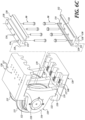
FIGURES 6A-6D illustrate an assembly sequence for the cutter assembly shown inFIGURE 2 . - The rotating main cutter head for a tunnel boring machine will typically have a number of cutter assemblies mounted to the cutter head and positioned to engage the strata, rock and/or soil to be bored. The number and placement of cutter assemblies will vary between tunnel boring machines, for example, depending on the size of the cutter head and the characteristics of the material that will be encountered by the tunnel boring machine. The cutter head may also have other devices to facilitate tunnel boring, for example non-rotating spikes or the like.
- A cutter assembly 100 (including mounting components) in accordance with the present invention is shown in a perspective view in
FIGURE 2 . A front view of thecutter assembly 100 is shown inFIGURE 3 . Thecutter assembly 100 includes oppositely disposedhousing mounts 120 and acutter ring assembly 110, which in this embodiment includes twocutter rings 115 rotatably mounted between the housing mounts 120 on three bridging supports 116. Typically the housing mounts 120 are semi-permanently fixed to corresponding mounting plates (not shown) on the main cutter head of a tunnel boring machine, for example, by welding the housing mounts to the corresponding mounting plates. - A pair of
elongate wedge members 130 secures the bridging supports 116 to an associated one of the housing mounts 120. Although two cutter rings 115 are shown, it will be appreciated by persons of skill in the art that cutter assemblies in accordance with the present invention may include one, or more than two, cutter rings 115. In prior art cutter assemblies, for example the cutter assembly shown inFIGURE 1 , the shaft 13 (and axis of rotation of the cutter ring) is disposed generally perpendicular to the housing mounts 20L, 20R. Theshaft 113 in thecutter assembly 100 shown inFIGURE 2 is parallel to the housing mounts 120 and in a center-plane between the housing mounts 120. The cutter rings 115 therefore are mounted to rotate about anaxis 114 parallel to, and in a center-plane between, the housing mounts 120. - Each of the housing mounts 120 includes a
plate portion 121 fixable to the main cutter head of a tunnel boring machine, aforward abutment flange 122 extending from theplate portion 121, and arearward portion 126 having spaced-apartintegral seat portions 124 definingchannels 125 between the integral seat portions 124 (see also,FIGURE 6A ). Theabutment flanges 122 may optionally include one ormore notches 123 sized and positioned to accommodate a radially outer portion ofrespective cutter ring 115. In this embodiment, field-replaceable wedge seats 140 are removably attached to theplate portions 121, providing a replaceable seating structure for the associatedelongate wedge member 130. Atransverse channel 128 in each of the housing mounts 120 is configured to receive the corresponding removable wedge seats 140. Alternatively wedge seats may be formed integrally with the corresponding housing mount, for example by extending theintegral seat portions 124. - Refer now also to
FIGURE 4 , which shows a sectional view of thecutter assembly 100 through section 4-4 indicated onFIGURE 3 . Thecutter ring assembly 110 includes ashaft 113 that is fixedly supported by the bridging supports 116. In this embodiment asingle shaft 113 engages the end bridging supports 116 and extends through themiddle bridging support 116. In other embodiments the shaft may comprise two or more separable portions. Each of the cutter rings 115 are rotatably mounted on theshaft 113 with a pair of bearing assemblies, each bearing assembly havinginner bearing races 112A that engage theshaft 113, outer bearingraces 112B that engage the cutter rings 115, and a plurality of taperedroller bearings 112C.Rotary seal groups 111 are also shown. Therotary seal groups 111 may be, for example, mechanical face seals. - Refer now also to
FIGURE 5 , which shows a plan view of thecutter assembly 100. The bridging supports 116 are generally T-shaped with a cutterring mounting portion 117 that extends between and away from the housing mounts 120, and wedge-shapedend portions 118 that abut thecorresponding abutment flange 122 of the housing mounts 120. The wedge-shapedend portions 118 of the bridging supports 116 define first wedge faces 119. - The
elongate wedge members 130 are each removably attached to a corresponding one of the housing mounts 120 withbolts 90. Referring still toFIGURE 5 , eachwedge member 130 has awedge portion 131, disposed between the associatedremovable seat 140 and the bridgingsupport end portions 118 on the same side, and aninner portion 133. Thewedge portion 131 defines aseating surface 138 that abuts theremovable wedge seat 140, and asecond wedge face 139. Thesecond wedge face 139 is configured to slidably engage the first wedge faces 119 of the associatedend portions 118 of each of the bridging supports 116. In this embodiment theinner portion 133 extends inwardly from thewedge portion 131 and the associatedhousing mount 120, and further includes spaced-apartflanges 132. Theinner portion 133 of eachwedge member 130 significantly improves the elastic section modulus properties of thewedge member 130. Theinner portions 133 in this embodiment include anextension arm 135 that extends rearwardly and may facilitate removal of the wedge member 130 (for example to service theassembly 100 in the field) by providing the user with a leverage arm during removal to assist in prying thewedge member 130 away from thehousing mount 120 after thebolts 90 have been removed. - Each
elongate wedge portion 131 extends between and slidably engages the correspondingremovable seat 140 and the bridgingsupport end portions 118. It will be appreciated that the first wedge faces 119 of theend portions 118 and thesecond wedge face 139 of thewedge portion 131 are configured to slidably engage, such that urging thewedge member 130 towards the corresponding housing mount 120 (with attachment bolts 90) will produce clamping forces on the bridgingsupport end portions 118. Thewedge portion 131 is sized and configured such that very large clamping forces may be produced on theend portions 118 as thebolts 90 are tightened, resulting in a large preload on the wedge-shapedend portion 118. Moreover, the magnitude of preload may be designed into thewedge members 130. For example, a larger preload may be achieved for a given bolt tension by providing a smaller wedge angle. - Preloading the
end portions 118 of the bridging supports 116 provides structural advantages during tunnel boring operations. In particular, the cutter rings 115 are pressed with great force against the rock face (or other strata), and as the main cutter head rotates large time-varying forces are produced that must be reacted through thecutter assembly 100. In particular, the large forces have a load path from thecutter ring 115, to theshaft 113, to the bridging supports 116, to thewedge member 130, and then to the housing mounts 120 (through the removable wedge seat 140). These large forces urge the bridgingsupport end portions 118 away from abutment with the housing mountsabutment flanges 122. It is important that the bridging supportsend portions 118 remain securely clamped between theabutment flange 122 and thewedge member 130 during tunnel boring, such that theend portions 118 do not move away from theabutment flange 122. In thecutter ring assembly 110 thewedge members 130 urge theend portions 118 in the direction directly opposed to the external boring forces. Preloading theend portions 118 towards theabutment flange 122 resists undesired motion of thecutter ring assembly 110 in the housing mounts 120. - Refer now to
FIGURES 6A-6D , which illustrate the method for assembling the housing mount assemblies and installing thecutter ring assembly 110 into the housing mounts 120. Referring first toFIGURE 6A , theremovable seats 140 in this embodiment are elongate members having abase portion 148 sized and shaped to slidably engage thetransverse channel 128 of thecorresponding housing mount 120. A plurality of spaced-apartseat portions 144 extend from thebase portion 148, defining a plurality ofchannels 145 between theseat portions 144, and includingchannels 145 outboard of theseat portions 144. As seen most clearly inFIGURE 6B , theseat portions 144 andchannels 145 are configured to abut and extend the correspondingintegral seat portions 124 andchannels 125 in thecorresponding housing mount 120 when theremovable wedge seat 140 is installed in thehousing mount 120. - It will be appreciated that a unique aspect of the
cutter assembly 100 is thechannels 125 that are located to accommodate the cutter ring assembly 110 (cutter rings 115 and bridging supports 116) and, if theremovable seat members 140 are used, the correspondingchannels 145 in theremovable seat members 140. Thesechannels cutter ring assembly 110 to be installed (and removed) inline. Thecutter ring assembly 110 is installed by sliding thecutter ring assembly 110 along a straight path from the back end of the housing mounts 120 forward until the bridging supports 116 abut theforward abutment flanges 122 of the housing mounts 120, and then installing theelongate wedge members 130 to eachhousing mount 120. For example, thebolts 90 may be tightened to a predetermined torque to produce a desired clamping force on the associatedend portions 118. - Therefore, to install the
cutter ring assembly 110 in pre-installed housing mounts 120, the removable wedge seats 140 (if included) are positioned intransverse channels 128 in the corresponding housing mounts 120, aligning stepped through-holes 141 in theseats 140 with threadedholes 129 in thechannel 128. The wedge seats 140 are fixed to thehousing mount 120 withbolts 90. As discussed above, theremovable wedge seats 140 allow thecutter assemblies 100 to be serviced in the field without requiring removal of the housing mounts 120 from the main cutter head. - As illustrated in
FIGURE 6B , thecutter ring assembly 110 is then inserted between the housing mounts 120, such that the cutter rings 115 and bridgingsupports 116 slidably engage correspondingchannels 125. Thecutter ring assembly 110 is inserted until theend portions 118 of the bridging supports 116 abut theforward abutment flange 122 of the housing mounts 120 (FIGURE 6C ). - The
elongate wedge members 130 are then installed by inserting thewedge portions 131 between the correspondingremovable wedge seat 140 and bridgingsupport end portions 118, aligningapertures 134 on eachwedge member 130 with corresponding threadedapertures 127 in the housing mounts 120, such that thesecond wedge face 139 engages the first wedge faces 119 on thecorresponding end portions 118 of the bridging supports 116, and theseating surface 138 engages theremovable wedge seat 140. Thewedge members 130 are then attached to thehousing mount 120 withbolts 90 which are tightened to a predetermined torque, to produce a desired preloading of theend portions 118 against theabutment flange 122. - As shown in
FIGURE 6D , thecutter assembly 100 is relatively compact in size, because thecutter ring assembly 110 is installed without requiring a lateral shift commonly required in prior art mounting systems. The inline mounting is particularly advantageous in tunnel boring machines because it simplifies the installation and removal of the cutter ring assemblies, and allows more cutter ring assemblies to be fit onto a main cutter head of a given size. It will further be appreciated that cutter ring assemblies for tunnel boring machines are relatively massive components, and it is therefore not a simple task to laterally shift the position of the cutter ring assembly, particularly in the field. The inline mounting of thecutter ring assembly 110 of the present invention allows thecutter ring assembly 110 to be installed and removed with only an inline movement of theassembly 110 through the housing mounts 120. Moreover, the positioning and guiding of thecutter ring assembly 110 during installation and removal is facilitated by thechannels
Claims (9)
- A cutter assembly (100) for a tunnel boring machine comprising:a first housing mount (120) and a second housing mount (120), the first and second housing mounts (120) being configured to be fixed to the tunnel boring machine, each housing mount (120) having a plate portion (121), an abutment flange (122), and a plurality of spaced-apart seats (124);a cutter ring assembly (110) comprising at least two spaced-apart bridging supports (116), a shaft (113) supported by the at least two bridging supports (116), and at least one cutter ring (115) mounted for rotation on the shaft (113), wherein the at least two bridging supports (116) each comprise a shaft-mounting portion (117), a first end portion (118) extending from the shaft-mounting portion (117) and configured to abut the first housing mount abutment flange (122) and a second end portion (118) extending from the shaft-mounting portion (117) and configured to abut the second housing mount abutment flange (122), wherein the first and second end portions (118) each define a first wedge face (119);a first wedge member (130) attachable to the first housing mount (120) between the abutment flange (122) and the plurality of spaced-apart seats (124), the first wedge member (130) defining a second wedge face (139) that slidably engages the first wedge faces (119) of the first end portions (118) of each of the at least two bridging supports (116); anda second wedge member (130) attachable to the second housing mount (120) between the abutment flange (122) and the plurality of spaced-apart seats (124), the second wedge member (130) defining a second wedge face (139) that slidably engages the first wedge faces (119) of the second end portions (118) of each of the at least two bridging supports (116);characterized in that the first and second housing mounts (120) define a plurality of channels (125) at a back end of the first and second housing mounts (120) and configured to slidably engage the at least two bridging supports (116) and the at least one cutter ring (115) such that the cutter ring assembly (110) is slidable along a straight path from a back end of the housing mounts (120) to a position wherein the first and second end members (118) of the bridging supports (117) abut the abutment flange (122) of the first and second housing mounts (120).
- The cutter assembly (100) of Claim 1, wherein the at least two spaced-apart bridging supports (116) comprise three spaced-apart bridging supports (116) and further wherein the at least one cutter ring (110) comprises two cutter rings (110) mounted for rotation on the shaft (113).
- The cutter assembly (100) of Claim 1, wherein the at least one cutter ring (110) is configured to rotate about an axis that is parallel to the first and second housing mounts (120).
- The cutter assembly (100) of Claim 1, wherein the first wedge member (130) is adjustably attachable to the first housing mount (120), wherein the first wedge member (130) is configured to clamp the first end portions (118) of the at least two bridging supports (116) against the abutment flange (122) of the first housing mount (120) to produce a controllable clamping force on the first end portions (118).
- The cutter assembly (100) of Claim 1, wherein the first and second wedge members (130) further comprise an inner portion (133) defining a leverage arm (135) and at least one flange (132).
- The cutter ring assembly (100) of Claim 5, wherein the inner portion (133) of the first and second wedge members further comprises a pair of flanges (132).
- The cutter assembly (100) of Claim 1, wherein the abutment flanges (122) of the first and second housing mounts (130) further comprise at least one notch (123) configured to accommodate the at least one cutter ring (115).
- The cutter assembly of Claim 1, wherein the first wedge member (130) is an elongate member that extends from a first side of the first housing mount (120) to an opposite side of the first housing mount (120).
- The cutter assembly of Claim 1, wherein the first and second housing mounts (120) each further comprises a transverse channel (128) in the plate portion (121) adjacent to the plurality of spaced-apart seats (124) and a removable wedge seat (140) configured to slidably engage the channel (128) and abut the plurality of spaced-apart seats (124), wherein the removable wedge seats (140) each abut a corresponding seating surface (138) of the corresponding first and second wedge members (128).
Applications Claiming Priority (2)
| Application Number | Priority Date | Filing Date | Title |
|---|---|---|---|
| US201762508030P | 2017-05-18 | 2017-05-18 | |
| PCT/US2018/033392 WO2018213706A1 (en) | 2017-05-18 | 2018-05-18 | Cutter housing with inline mounting |
Publications (4)
| Publication Number | Publication Date |
|---|---|
| EP3625436A1 EP3625436A1 (en) | 2020-03-25 |
| EP3625436A4 EP3625436A4 (en) | 2021-05-19 |
| EP3625436B1 true EP3625436B1 (en) | 2024-07-10 |
| EP3625436C0 EP3625436C0 (en) | 2024-07-10 |
Family
ID=64270376
Family Applications (1)
| Application Number | Title | Priority Date | Filing Date |
|---|---|---|---|
| EP18801376.7A Active EP3625436B1 (en) | 2017-05-18 | 2018-05-18 | Cutter housing with inline mounting |
Country Status (5)
| Country | Link |
|---|---|
| US (1) | US10480318B2 (en) |
| EP (1) | EP3625436B1 (en) |
| JP (1) | JP7164772B2 (en) |
| CN (1) | CN110785540B (en) |
| WO (1) | WO2018213706A1 (en) |
Families Citing this family (4)
| Publication number | Priority date | Publication date | Assignee | Title |
|---|---|---|---|---|
| CN110080788B (en) * | 2019-06-06 | 2024-09-20 | 中国铁建重工集团股份有限公司 | Hob box device of shield tunneling machine |
| CN112593965B (en) * | 2020-12-08 | 2022-10-21 | 安徽唐兴装备科技股份有限公司 | Hob can scrape push bench of soil |
| DE102021102833A1 (en) * | 2021-02-08 | 2022-08-11 | Aktiebolaget Skf | cutting ring assembly |
| CN113153343B (en) * | 2021-05-28 | 2022-10-21 | 安徽唐兴装备科技股份有限公司 | High-efficient pipe pushing jack blade disc with hobbing cutter device |
Citations (5)
| Publication number | Priority date | Publication date | Assignee | Title |
|---|---|---|---|---|
| US4193637A (en) * | 1978-08-07 | 1980-03-18 | The Robbins Company | Rotary cutterhead for an earth boring machine |
| JP2013127182A (en) * | 2011-12-19 | 2013-06-27 | Kawasaki Heavy Ind Ltd | Cutter holder for roller cutter |
| WO2015063322A2 (en) * | 2013-11-04 | 2015-05-07 | Bouygues Travaux Publics | Cutting tool holder for a tunnel-boring machine and associated cutting assembly |
| EP3012403A1 (en) * | 2014-10-16 | 2016-04-27 | NFM Technologies | System for attaching a cutting tool to a cutting head of a tunnel-boring machine and tunnel-boring machine comprising such an attachment system |
| US20170122105A1 (en) * | 2015-10-28 | 2017-05-04 | The Robbins Company | Cutter assembly with inline mounting |
Family Cites Families (23)
| Publication number | Priority date | Publication date | Assignee | Title |
|---|---|---|---|---|
| US4202418A (en) | 1978-05-01 | 1980-05-13 | The Robbins Company | Roller cutter mounts |
| USRE31511E (en) | 1978-08-07 | 1984-01-31 | The Robbins Company | Rotary cutterhead for an earth boring machine |
| US4270618A (en) | 1979-04-20 | 1981-06-02 | The Robbins Company | Earth boring apparatus |
| US4548443A (en) | 1984-07-03 | 1985-10-22 | The Robbins Company | Tunnel boring machine |
| US5205612A (en) | 1990-05-17 | 1993-04-27 | Z C Mines Pty. Ltd. | Transport apparatus and method of forming same |
| CN2138185Y (en) * | 1992-08-12 | 1993-07-14 | 河南省耐磨材料高新技术开发公司 | Wedge tooth hobbing cutter |
| US5421422A (en) | 1993-11-19 | 1995-06-06 | Boretec Inc | Roller cutter mount for tunneling machine |
| US5598895A (en) | 1995-01-19 | 1997-02-04 | Atlas Copco Robbins Inc. | Cutter assembly having a plurality of independently rotatable cutting units thereon |
| JP2836740B2 (en) | 1996-08-27 | 1998-12-14 | 川崎重工業株式会社 | Cutter mounting mechanism and cutter holder for tunnel excavator |
| DE69708852T2 (en) | 1996-09-03 | 2002-06-06 | Hitachi Construction Machinery Co., Ltd. | TUNNEL DRIVING MACHINE AND MANUFACTURING METHOD |
| JP3834987B2 (en) | 1998-01-30 | 2006-10-18 | 石川島播磨重工業株式会社 | Roller cutter mounting device |
| JP3329274B2 (en) | 1998-06-29 | 2002-09-30 | 三菱マテリアル株式会社 | Roller cutter |
| JP4135952B2 (en) | 2005-09-05 | 2008-08-20 | 川崎重工業株式会社 | Roller cutter fixing device for tunnel excavator |
| AU2009260436B2 (en) * | 2008-05-30 | 2013-01-24 | The Robbins Company | Apparatus and method for monitoring tunnel boring efficiency |
| CN101440710B (en) * | 2008-12-23 | 2010-12-01 | 沈阳重型机械集团有限责任公司 | Shield machine roller cutter back mounting type self-positioning fixing device |
| AU2010335304B2 (en) | 2009-12-22 | 2015-12-17 | Bouygues Travaux Publics | Method for replacing a tunnel boring machine disk cutter, handling device and disk cutter suited to such a method |
| DE102011114830B3 (en) | 2011-10-05 | 2013-03-07 | Herrenknecht Ag | Apparatus for monitoring the rotational condition of a cutting roller assembly of a shield tunneling machine and cutting roller assembly for a shield tunneling machine |
| CN202325532U (en) * | 2011-10-09 | 2012-07-11 | 盾建重工制造有限公司 | Fixed structure of shaft seat fixed-type center cutter of shield machine and cutter box for center cutter |
| CN202266269U (en) * | 2011-10-09 | 2012-06-06 | 盾建重工制造有限公司 | Installation structure for trebling-end-cover double-edged hob of shield machine in cylinder cutter box |
| AT13486U1 (en) | 2012-09-19 | 2014-01-15 | Montanuniv Leoben | Easy-to-use sensor technology for determining a mechanical load on a mining machine of a tunnel boring machine |
| DE102014105014A1 (en) | 2014-04-08 | 2015-10-08 | Montanuniversität Leoben | High-precision sensor for determining a mechanical load of a mining tool of a tunnel boring machine |
| CN105114086A (en) * | 2015-08-28 | 2015-12-02 | 重庆市腾瀚工贸有限公司 | Hob mounting structure of shield tunneling machine |
| EP3368746A4 (en) | 2015-10-30 | 2019-06-26 | The Robbins Company | Clamped-ring cutter assembly for tunnel boring machine |
-
2018
- 2018-05-17 US US15/982,856 patent/US10480318B2/en active Active
- 2018-05-18 WO PCT/US2018/033392 patent/WO2018213706A1/en not_active Ceased
- 2018-05-18 CN CN201880042166.6A patent/CN110785540B/en not_active Expired - Fee Related
- 2018-05-18 EP EP18801376.7A patent/EP3625436B1/en active Active
- 2018-05-18 JP JP2019563269A patent/JP7164772B2/en active Active
Patent Citations (5)
| Publication number | Priority date | Publication date | Assignee | Title |
|---|---|---|---|---|
| US4193637A (en) * | 1978-08-07 | 1980-03-18 | The Robbins Company | Rotary cutterhead for an earth boring machine |
| JP2013127182A (en) * | 2011-12-19 | 2013-06-27 | Kawasaki Heavy Ind Ltd | Cutter holder for roller cutter |
| WO2015063322A2 (en) * | 2013-11-04 | 2015-05-07 | Bouygues Travaux Publics | Cutting tool holder for a tunnel-boring machine and associated cutting assembly |
| EP3012403A1 (en) * | 2014-10-16 | 2016-04-27 | NFM Technologies | System for attaching a cutting tool to a cutting head of a tunnel-boring machine and tunnel-boring machine comprising such an attachment system |
| US20170122105A1 (en) * | 2015-10-28 | 2017-05-04 | The Robbins Company | Cutter assembly with inline mounting |
Also Published As
| Publication number | Publication date |
|---|---|
| JP7164772B2 (en) | 2022-11-02 |
| US10480318B2 (en) | 2019-11-19 |
| EP3625436A1 (en) | 2020-03-25 |
| US20180334906A1 (en) | 2018-11-22 |
| WO2018213706A1 (en) | 2018-11-22 |
| EP3625436C0 (en) | 2024-07-10 |
| CN110785540B (en) | 2021-04-09 |
| JP2020519799A (en) | 2020-07-02 |
| EP3625436A4 (en) | 2021-05-19 |
| CN110785540A (en) | 2020-02-11 |
Similar Documents
| Publication | Publication Date | Title |
|---|---|---|
| EP3368745B1 (en) | Cutter assembly with inline mounting | |
| US10480318B2 (en) | Cutter housing with inline mounting | |
| US9010872B2 (en) | Tunnel boring machine with cutterhead support assembly supporting a variable number of drive systems | |
| US20080093912A1 (en) | Cutting Tool Holding Apparatus And Method Of Use | |
| CN102553675B (en) | Pick holder | |
| CN108625767B (en) | Rotary unit and method for adjusting bearing clearance | |
| US10539017B2 (en) | Cutter housing with field-replaceable seats | |
| US11174683B2 (en) | Tapered joint for securing cone arm in hole opener | |
| EP3116769A1 (en) | Replaceable mounting apparatus for reducing elements | |
| JP4135952B2 (en) | Roller cutter fixing device for tunnel excavator | |
| EP3538743B1 (en) | Roller cutter unit for undercutting machine | |
| US10018042B2 (en) | Clamped-ring cutter assembly for tunnel boring machine | |
| JP3318297B2 (en) | Excavator | |
| GB2403121A (en) | Blade mounting for rotary tilling machines | |
| JP2000002088A (en) | Underground excavator disc cutter | |
| JPH0240839B2 (en) | TONNERUKUTSUSAKUKINOKATSUTADEISUKU | |
| JP2003106092A (en) | Roller bit device | |
| AU2006246347A1 (en) | Cutting tool holding apparatus and method of use |
Legal Events
| Date | Code | Title | Description |
|---|---|---|---|
| STAA | Information on the status of an ep patent application or granted ep patent |
Free format text: STATUS: THE INTERNATIONAL PUBLICATION HAS BEEN MADE |
|
| PUAI | Public reference made under article 153(3) epc to a published international application that has entered the european phase |
Free format text: ORIGINAL CODE: 0009012 |
|
| STAA | Information on the status of an ep patent application or granted ep patent |
Free format text: STATUS: REQUEST FOR EXAMINATION WAS MADE |
|
| 17P | Request for examination filed |
Effective date: 20191217 |
|
| AK | Designated contracting states |
Kind code of ref document: A1 Designated state(s): AL AT BE BG CH CY CZ DE DK EE ES FI FR GB GR HR HU IE IS IT LI LT LU LV MC MK MT NL NO PL PT RO RS SE SI SK SM TR |
|
| AX | Request for extension of the european patent |
Extension state: BA ME |
|
| DAV | Request for validation of the european patent (deleted) | ||
| DAX | Request for extension of the european patent (deleted) | ||
| A4 | Supplementary search report drawn up and despatched |
Effective date: 20210419 |
|
| RIC1 | Information provided on ipc code assigned before grant |
Ipc: E21D 9/08 20060101AFI20210413BHEP Ipc: E21D 9/10 20060101ALI20210413BHEP Ipc: E21B 10/12 20060101ALI20210413BHEP Ipc: E21C 25/08 20060101ALI20210413BHEP Ipc: E21C 25/18 20060101ALI20210413BHEP |
|
| RIN1 | Information on inventor provided before grant (corrected) |
Inventor name: SMADING, STEPHEN M. Inventor name: GALBRAITH, ROSS D. Inventor name: LENABURG, CARL E. |
|
| STAA | Information on the status of an ep patent application or granted ep patent |
Free format text: STATUS: EXAMINATION IS IN PROGRESS |
|
| 17Q | First examination report despatched |
Effective date: 20221223 |
|
| GRAP | Despatch of communication of intention to grant a patent |
Free format text: ORIGINAL CODE: EPIDOSNIGR1 |
|
| STAA | Information on the status of an ep patent application or granted ep patent |
Free format text: STATUS: GRANT OF PATENT IS INTENDED |
|
| INTG | Intention to grant announced |
Effective date: 20230912 |
|
| GRAS | Grant fee paid |
Free format text: ORIGINAL CODE: EPIDOSNIGR3 |
|
| 19U | Interruption of proceedings before grant |
Effective date: 20191218 |
|
| 19W | Proceedings resumed before grant after interruption of proceedings |
Effective date: 20240402 |
|
| RAP3 | Party data changed (applicant data changed or rights of an application transferred) |
Owner name: GLOBAL TBM COMPANY |
|
| GRAA | (expected) grant |
Free format text: ORIGINAL CODE: 0009210 |
|
| STAA | Information on the status of an ep patent application or granted ep patent |
Free format text: STATUS: THE PATENT HAS BEEN GRANTED |
|
| AK | Designated contracting states |
Kind code of ref document: B1 Designated state(s): AL AT BE BG CH CY CZ DE DK EE ES FI FR GB GR HR HU IE IS IT LI LT LU LV MC MK MT NL NO PL PT RO RS SE SI SK SM TR |
|
| REG | Reference to a national code |
Ref country code: CH Ref legal event code: EP |
|
| REG | Reference to a national code |
Ref country code: DE Ref legal event code: R096 Ref document number: 602018071630 Country of ref document: DE |
|
| U01 | Request for unitary effect filed |
Effective date: 20240731 |
|
| U07 | Unitary effect registered |
Designated state(s): AT BE BG DE DK EE FI FR IT LT LU LV MT NL PT SE SI Effective date: 20240819 |
|
| PG25 | Lapsed in a contracting state [announced via postgrant information from national office to epo] |
Ref country code: NO Free format text: LAPSE BECAUSE OF FAILURE TO SUBMIT A TRANSLATION OF THE DESCRIPTION OR TO PAY THE FEE WITHIN THE PRESCRIBED TIME-LIMIT Effective date: 20241010 |
|
| PG25 | Lapsed in a contracting state [announced via postgrant information from national office to epo] |
Ref country code: GR Free format text: LAPSE BECAUSE OF FAILURE TO SUBMIT A TRANSLATION OF THE DESCRIPTION OR TO PAY THE FEE WITHIN THE PRESCRIBED TIME-LIMIT Effective date: 20241011 Ref country code: PL Free format text: LAPSE BECAUSE OF FAILURE TO SUBMIT A TRANSLATION OF THE DESCRIPTION OR TO PAY THE FEE WITHIN THE PRESCRIBED TIME-LIMIT Effective date: 20240710 |
|
| PG25 | Lapsed in a contracting state [announced via postgrant information from national office to epo] |
Ref country code: IS Free format text: LAPSE BECAUSE OF FAILURE TO SUBMIT A TRANSLATION OF THE DESCRIPTION OR TO PAY THE FEE WITHIN THE PRESCRIBED TIME-LIMIT Effective date: 20241110 |
|
| PG25 | Lapsed in a contracting state [announced via postgrant information from national office to epo] |
Ref country code: HR Free format text: LAPSE BECAUSE OF FAILURE TO SUBMIT A TRANSLATION OF THE DESCRIPTION OR TO PAY THE FEE WITHIN THE PRESCRIBED TIME-LIMIT Effective date: 20240710 |
|
| PG25 | Lapsed in a contracting state [announced via postgrant information from national office to epo] |
Ref country code: ES Free format text: LAPSE BECAUSE OF FAILURE TO SUBMIT A TRANSLATION OF THE DESCRIPTION OR TO PAY THE FEE WITHIN THE PRESCRIBED TIME-LIMIT Effective date: 20240710 Ref country code: RS Free format text: LAPSE BECAUSE OF FAILURE TO SUBMIT A TRANSLATION OF THE DESCRIPTION OR TO PAY THE FEE WITHIN THE PRESCRIBED TIME-LIMIT Effective date: 20241010 |
|
| PG25 | Lapsed in a contracting state [announced via postgrant information from national office to epo] |
Ref country code: RS Free format text: LAPSE BECAUSE OF FAILURE TO SUBMIT A TRANSLATION OF THE DESCRIPTION OR TO PAY THE FEE WITHIN THE PRESCRIBED TIME-LIMIT Effective date: 20241010 Ref country code: PL Free format text: LAPSE BECAUSE OF FAILURE TO SUBMIT A TRANSLATION OF THE DESCRIPTION OR TO PAY THE FEE WITHIN THE PRESCRIBED TIME-LIMIT Effective date: 20240710 Ref country code: NO Free format text: LAPSE BECAUSE OF FAILURE TO SUBMIT A TRANSLATION OF THE DESCRIPTION OR TO PAY THE FEE WITHIN THE PRESCRIBED TIME-LIMIT Effective date: 20241010 Ref country code: IS Free format text: LAPSE BECAUSE OF FAILURE TO SUBMIT A TRANSLATION OF THE DESCRIPTION OR TO PAY THE FEE WITHIN THE PRESCRIBED TIME-LIMIT Effective date: 20241110 Ref country code: HR Free format text: LAPSE BECAUSE OF FAILURE TO SUBMIT A TRANSLATION OF THE DESCRIPTION OR TO PAY THE FEE WITHIN THE PRESCRIBED TIME-LIMIT Effective date: 20240710 Ref country code: GR Free format text: LAPSE BECAUSE OF FAILURE TO SUBMIT A TRANSLATION OF THE DESCRIPTION OR TO PAY THE FEE WITHIN THE PRESCRIBED TIME-LIMIT Effective date: 20241011 Ref country code: ES Free format text: LAPSE BECAUSE OF FAILURE TO SUBMIT A TRANSLATION OF THE DESCRIPTION OR TO PAY THE FEE WITHIN THE PRESCRIBED TIME-LIMIT Effective date: 20240710 |
|
| PG25 | Lapsed in a contracting state [announced via postgrant information from national office to epo] |
Ref country code: SM Free format text: LAPSE BECAUSE OF FAILURE TO SUBMIT A TRANSLATION OF THE DESCRIPTION OR TO PAY THE FEE WITHIN THE PRESCRIBED TIME-LIMIT Effective date: 20240710 |
|
| PG25 | Lapsed in a contracting state [announced via postgrant information from national office to epo] |
Ref country code: CZ Free format text: LAPSE BECAUSE OF FAILURE TO SUBMIT A TRANSLATION OF THE DESCRIPTION OR TO PAY THE FEE WITHIN THE PRESCRIBED TIME-LIMIT Effective date: 20240710 |
|
| PG25 | Lapsed in a contracting state [announced via postgrant information from national office to epo] |
Ref country code: SK Free format text: LAPSE BECAUSE OF FAILURE TO SUBMIT A TRANSLATION OF THE DESCRIPTION OR TO PAY THE FEE WITHIN THE PRESCRIBED TIME-LIMIT Effective date: 20240710 |
|
| PLBE | No opposition filed within time limit |
Free format text: ORIGINAL CODE: 0009261 |
|
| STAA | Information on the status of an ep patent application or granted ep patent |
Free format text: STATUS: NO OPPOSITION FILED WITHIN TIME LIMIT |
|
| U20 | Renewal fee for the european patent with unitary effect paid |
Year of fee payment: 8 Effective date: 20250424 |
|
| 26N | No opposition filed |
Effective date: 20250411 |
|
| REG | Reference to a national code |
Ref country code: CH Ref legal event code: H13 Free format text: ST27 STATUS EVENT CODE: U-0-0-H10-H13 (AS PROVIDED BY THE NATIONAL OFFICE) Effective date: 20251223 |
|
| PG25 | Lapsed in a contracting state [announced via postgrant information from national office to epo] |
Ref country code: CH Free format text: LAPSE BECAUSE OF NON-PAYMENT OF DUE FEES Effective date: 20250531 |
|
| GBPC | Gb: european patent ceased through non-payment of renewal fee |
Effective date: 20250518 |
|
| PG25 | Lapsed in a contracting state [announced via postgrant information from national office to epo] |
Ref country code: MC Free format text: LAPSE BECAUSE OF FAILURE TO SUBMIT A TRANSLATION OF THE DESCRIPTION OR TO PAY THE FEE WITHIN THE PRESCRIBED TIME-LIMIT Effective date: 20240710 |
|
| PG25 | Lapsed in a contracting state [announced via postgrant information from national office to epo] |
Ref country code: GB Free format text: LAPSE BECAUSE OF NON-PAYMENT OF DUE FEES Effective date: 20250518 |
|
| PG25 | Lapsed in a contracting state [announced via postgrant information from national office to epo] |
Ref country code: IE Free format text: LAPSE BECAUSE OF NON-PAYMENT OF DUE FEES Effective date: 20250518 |
|
| PG25 | Lapsed in a contracting state [announced via postgrant information from national office to epo] |
Ref country code: RO Free format text: LAPSE BECAUSE OF FAILURE TO SUBMIT A TRANSLATION OF THE DESCRIPTION OR TO PAY THE FEE WITHIN THE PRESCRIBED TIME-LIMIT Effective date: 20240710 |
|
| U20 | Renewal fee for the european patent with unitary effect paid |
Year of fee payment: 9 Effective date: 20260420 |
|
| PGFP | Annual fee paid to national office [announced via postgrant information from national office to epo] |
Ref country code: TR Payment date: 20260512 Year of fee payment: 9 |
|
| PG25 | Lapsed in a contracting state [announced via postgrant information from national office to epo] |
Ref country code: CY Free format text: LAPSE BECAUSE OF FAILURE TO SUBMIT A TRANSLATION OF THE DESCRIPTION OR TO PAY THE FEE WITHIN THE PRESCRIBED TIME-LIMIT Effective date: 20240710 |