EP3625403B1 - Building panel adapted to be mounted at a ceiling or wall of a room and method of manufacturing such building panel - Google Patents
Building panel adapted to be mounted at a ceiling or wall of a room and method of manufacturing such building panel Download PDFInfo
- Publication number
- EP3625403B1 EP3625403B1 EP17726708.5A EP17726708A EP3625403B1 EP 3625403 B1 EP3625403 B1 EP 3625403B1 EP 17726708 A EP17726708 A EP 17726708A EP 3625403 B1 EP3625403 B1 EP 3625403B1
- Authority
- EP
- European Patent Office
- Prior art keywords
- textile
- frame profile
- spring
- profile member
- building panel
- Prior art date
- Legal status (The legal status is an assumption and is not a legal conclusion. Google has not performed a legal analysis and makes no representation as to the accuracy of the status listed.)
- Active
Links
Images


Classifications
-
- E—FIXED CONSTRUCTIONS
- E04—BUILDING
- E04B—GENERAL BUILDING CONSTRUCTIONS; WALLS, e.g. PARTITIONS; ROOFS; FLOORS; CEILINGS; INSULATION OR OTHER PROTECTION OF BUILDINGS
- E04B9/00—Ceilings; Construction of ceilings, e.g. false ceilings; Ceiling construction with regard to insulation
- E04B9/04—Ceilings; Construction of ceilings, e.g. false ceilings; Ceiling construction with regard to insulation comprising slabs, panels, sheets or the like
- E04B9/0428—Ceilings; Construction of ceilings, e.g. false ceilings; Ceiling construction with regard to insulation comprising slabs, panels, sheets or the like having a closed frame around the periphery
-
- E—FIXED CONSTRUCTIONS
- E04—BUILDING
- E04B—GENERAL BUILDING CONSTRUCTIONS; WALLS, e.g. PARTITIONS; ROOFS; FLOORS; CEILINGS; INSULATION OR OTHER PROTECTION OF BUILDINGS
- E04B9/00—Ceilings; Construction of ceilings, e.g. false ceilings; Ceiling construction with regard to insulation
- E04B9/04—Ceilings; Construction of ceilings, e.g. false ceilings; Ceiling construction with regard to insulation comprising slabs, panels, sheets or the like
- E04B2009/0492—Ceilings; Construction of ceilings, e.g. false ceilings; Ceiling construction with regard to insulation comprising slabs, panels, sheets or the like with fabrics tensioned on frames
-
- E—FIXED CONSTRUCTIONS
- E04—BUILDING
- E04B—GENERAL BUILDING CONSTRUCTIONS; WALLS, e.g. PARTITIONS; ROOFS; FLOORS; CEILINGS; INSULATION OR OTHER PROTECTION OF BUILDINGS
- E04B9/00—Ceilings; Construction of ceilings, e.g. false ceilings; Ceiling construction with regard to insulation
- E04B9/04—Ceilings; Construction of ceilings, e.g. false ceilings; Ceiling construction with regard to insulation comprising slabs, panels, sheets or the like
- E04B9/0407—Ceilings; Construction of ceilings, e.g. false ceilings; Ceiling construction with regard to insulation comprising slabs, panels, sheets or the like being stiff and curved
-
- E—FIXED CONSTRUCTIONS
- E04—BUILDING
- E04F—FINISHING WORK ON BUILDINGS, e.g. STAIRS, FLOORS
- E04F13/00—Coverings or linings, e.g. for walls or ceilings
- E04F13/002—Coverings or linings, e.g. for walls or ceilings made of webs, e.g. of fabrics, or wallpaper, used as coverings or linings
- E04F13/005—Stretched foil- or web-like elements attached with edge gripping devices
Definitions
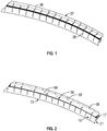
- the present invention relates to a building panel adapted to be mounted at a ceiling or wall of a room so that a framework of the building panel has a room-facing side and a building-facing side, wherein the framework includes a peripheral frame formed by frame profile members, wherein a textile is extended over the room-facing side of the framework between the frame profile members, and wherein each edge of the textile is attached to a corresponding frame profile member by means of a spring-biased tensioning mechanism.
- Such building panels can generally be used to cover interior surfaces in buildings, for instance in auditoriums, open-plan offices, etc.
- buildings for instance in auditoriums, open-plan offices, etc.
- panels for covering of boundaries of a room, such as the ceiling, the walls or partitions placed within the room.
- Such panels can serve purely aesthetic purposes but can also be used to actively alter a room's characteristics, for instance relating to acoustic and thermal properties of the room.
- WO 2005/073482 A2 discloses a system of building panels for suspended ceilings.
- Each building panel includes a frame composed by profile members, and a room-facing side of the building panel is formed by a textile suspended between the profile members.
- Different tensioning systems are disclosed whereby the textile may be stretched evenly over the opening of the frame and thereby form a smooth flat surface visible from the room.
- the building panels disclosed are excellent when a smooth flat textile surface is desired, these building panels are generally not suitable if a curved textile surface is required.
- building panels having a curved textile surface visible from the room may be required for different reasons, such as for aesthetic or practical purposes.
- the required dimensions of such building panels may vary greatly.
- the object of the present invention is to provide a building panel suitable for extending smoothly curved textile surfaces of any desired size.
- the peripheral frame is composed by two opposed curved frame profile members and by two opposed straight frame profile members so that the extended textile forms a curved surface, each curved frame profile member is provided with a first spring-biased tensioning mechanism for tensioning the textile and each straight frame profile member is provided with a second spring-biased tensioning mechanism for tensioning the textile, and the first spring-biased tensioning mechanisms are of such a different mechanical construction than the second spring-biased tensioning mechanisms that each first spring-biased tensioning mechanism in the tensioned state of the textile provides a first tensioning force per unit edge length of the textile and each second spring-biased tensioning mechanism is adapted to provide a second maximum tensioning force per unit edge length of the textile, the first tensioning force per unit edge length of the textile being greater than the second maximum tensioning force per unit edge length of the textile.
- the first spring-biased tensioning mechanisms may extend the textile between the two opposed curved frame profile members by means of a relatively greater force per unit edge length of the textile, thereby ensuring that the textile forms an intended curvature over the entire length of the peripheral frame between the curved frame profile members, and the second spring-biased tensioning mechanisms may by means of a relatively smaller force per unit edge length of the textile ensure that the textile is suitably stretched between the two opposed straight frame profile members without negatively influencing the intended curvature of the textile.
- the second spring-biased tensioning mechanism may be of a simpler construction and may take up less space in the building panel than the first spring-biased tensioning mechanism.
- the first tensioning force per unit edge length of the textile is at least two times greater, preferably at least five times greater and most preferred at least ten times greater than the second maximum tensioning force per unit edge length of the textile.
- the two opposed curved frame profile members have identical curvatures.
- the first tensioning force per unit edge length of the textile provided by said first spring-biased tensioning mechanism is adjustable, preferably steplessly.
- each first spring-biased tensioning mechanism is arranged at least partly outside the corresponding curved frame profile member, and each second spring-biased tensioning mechanism is arranged inside a channel of the corresponding straight frame profile member.
- the first spring-biased tensioning mechanism may by means of sturdy components suitably be configured to provide a relatively large tensioning force, whereas the second spring-biased tensioning mechanism may by means of smaller components suitably take up relatively little space in the building panel.
- each first spring-biased tensioning mechanism includes at least one tension coil spring having a first end attached to a tension profile member forming part of the framework and being spaced from the curved frame profile member and a second end attached to the corresponding edge of the textile.
- the first end of said tension coil spring is attached to an adjustment mechanism attached to the tension profile member.
- the first end of said tension coil spring is attached to the eye of an eyebolt inserted through a hole in the tension profile member, and the bolt of the eyebolt is adjustably mounted in the hole of the tension profile member by means of a nut screwed onto the bolt.
- the second end of said tension coil spring is attached, preferably by means of a hook member, to an elongated profile attached along the corresponding edge of the textile.
- each curved frame profile member has a building-facing side and a room-facing side connected by means of a rounded edge about which the textile is bent, and the elongated profile is arranged in a channel in the building-facing side of the curved frame profile member and is preferably attached to the second end of said tension coil spring by means of a hook member extending through an opening in the curved frame profile member.
- the edge of the textile may suitably be attached to the first spring-biased tensioning mechanism at the building-facing side of the curved frame profile member, and at the same time the first spring-biased tensioning mechanism may include a relatively large tension coil spring situated outside the curved frame profile member.
- each straight frame profile member has a building-facing side and a room-facing side connected by means of a rounded edge about which the textile is bent
- each second spring-biased tensioning mechanism includes a bracket arranged in a channel in the building-facing side of the straight frame profile member, and the bracket is spring-biased sideward in the track in order to tension the textile between the opposed rounded edges of the opposed straight frame profile members.
- a suitable maximum tensioning force may be provided by the second spring-biased tensioning mechanism.
- the distance between the two opposed curved frame profile members is at least 2/3 of, preferably greater than and most preferably at least 4/3 of the distance between the two opposed straight frame profile members.
- each curved frame profile member is made from an extruded metal profile, preferably made of aluminium
- each curved frame profile member is provided with a number of lateral slits spaced from each other in the longitudinal direction of the curved frame profile member, each lateral slit extends only partly through the extruded metal profile, and each curved frame profile member is strengthened by means of a flat, curved metal plate attached to the extruded metal profile along its length.
- the flat, curved metal plate may easily be cut to the desired curvature, for instance by means of a laser cutter, and may compensate for the flexibility of the extruded profile member provided by the lateral slits. In this way, conveniently, the same type of extruded profile member may be employed for producing both the straight frame profile members and the curved frame profile members.
- the present invention further relates to a method of manufacturing a building panel adapted to be mounted at a ceiling or wall of a room so that a framework of the building panel has a room-facing side and a building-facing side, the framework including a peripheral frame formed by frame profile members, whereby a textile is extended over the room-facing side of the framework between the frame profile members, and whereby each edge of the textile is attached to a corresponding frame profile member by means of a spring-biased tensioning mechanism.
- the method is characterised in that the peripheral frame is composed by two opposed curved frame profile members and by two opposed straight frame profile members in order for the extended textile to form a curved surface, in that, firstly, the textile is tensioned to a first tensioning force per unit edge length of the textile in relation to each curved frame profile member by means of a first spring-biased tensioning mechanism and, secondly, the textile is tensioned to a second tensioning force per unit edge length of the textile in relation to each straight frame profile member by means of a second spring-biased tensioning mechanism, the first tensioning force per unit edge length of the textile being greater than the second tensioning force per unit edge length of the textile.
- the first spring-biased tensioning mechanisms may extend the textile between the two opposed curved frame profile members by means of a relatively greater force per unit edge length of the textile, thereby ensuring that the textile forms an intended curvature over the entire length of the peripheral frame between the curved frame profile members, and the second spring-biased tensioning mechanisms may by means of a relatively smaller force per unit edge length of the textile ensure that the textile is suitably stretched between the two opposed straight frame profile members without negatively influencing the intended curvature of the textile.
- the textile By firstly tensioning the textile by means of the relatively greater force by means of the first spring-biased tensioning mechanisms, it may be ensured that the textile forms said intended curvature over the entire length of the peripheral frame between the curved frame profile members before the textile is attached to the straight frame profile members. Thereby, the length of the textile between the opposed straight frame profile members may be adapted accordingly before attachment by means of the second spring-biased tensioning mechanisms. Therefore, the second spring-biased tensioning mechanisms may not need to be adapted to take up large variations in the length of the textile and may therefore be of a relatively simple construction as compared to the first spring-biased tensioning mechanisms.
- the second spring-biased tensioning mechanism may be of a relatively simpler construction and may take up less space in the building panel than the first spring-biased tensioning mechanism.
- the first tensioning force per unit edge length of the textile is at least two times greater, preferably at least five times greater and most preferred at least ten times greater than the second maximum tensioning force per unit edge length of the textile.
- the first tensioning force per unit edge length of the textile provided by the first spring-biased tensioning mechanism is adjusted, preferably steplessly, by means of the first spring-biased tensioning mechanism.
- the distance between the two opposed curved frame profile members is at least 2/3 of, preferably greater than and most preferably at least 4/3 of the distance between the two opposed straight frame profile members.
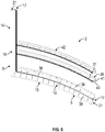
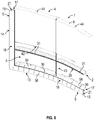
- the peripheral frame 5 is composed by two opposed curved frame profile members 13 of which only one in the lower part of Fig. 9 is illustrated and by two opposed straight frame profile members 14 of which only one to the right of the figure is illustrated.
- the part of the building panel 1 illustrated in Fig. 9 forms a (as seen in the figure) lower, right part of the entire building panel 1.
- the extended textile 9 forms a curved surface, which in the illustrated embodiment is concave seen from the room-facing side 3 of the framework 2.
- the extended textile 9 may form a curved surface which is convex.
- the extended textile 9 may form a curved surface which is partly cylindrical, such as a partly circular cylindrical surface.
- Each curved frame profile member 13 is provided with a first spring-biased tensioning mechanism 6 for tensioning the textile 9 as illustrated in more detail in Figs. 9 to 13 .
- each straight frame profile member 14 is provided with a second spring-biased tensioning mechanism 7 for tensioning the textile 9 as illustrated in more detail in Figs. 14 to 16 .
- the first spring-biased tensioning mechanisms 6 are of a different mechanical construction than the second spring-biased tensioning mechanisms 7, whereby each first spring-biased tensioning mechanism 6 is arranged to provide, in the tensioned state of the textile 9, a first tensioning force per unit edge length of the textile 9, and each second spring-biased tensioning mechanism 7 is adapted to provide a second maximum tensioning force per unit edge length of the textile 9, whereby the first tensioning force per unit edge length of the textile is greater than the second maximum tensioning force per unit edge length of the textile.
- the textile is extended by a relatively greater force (per unit edge length of the textile) in the direction extending between the two opposed curved frame profile members 13 than in the direction extending between the two opposed straight frame profile member 14.
- the tensioning force per unit edge length of the textile 9 is understood as the total tensioning force applied to the textile over a certain edge 18 of the textile 9 divided by the length of that edge of the textile.
- the first tensioning force per unit edge length of the textile is at least two times greater, preferably at least five times greater and most preferred at least ten times greater than the second maximum tensioning force per unit edge length of the textile.
- the two opposed curved frame profile members 13 have identical curvatures. It is further preferred, as it will be explained in further detail below, that the first tensioning force per unit edge length of the textile provided by said first spring-biased tensioning mechanism 6 is adjustable, preferably steplessly.
- each first spring-biased tensioning mechanism 6 is arranged at least partly outside the corresponding curved frame profile member 13, and each second spring-biased tensioning mechanism 7 is arranged inside a channel 21 of the corresponding straight frame profile member 14.
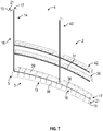
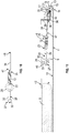
- each first spring-biased tensioning mechanism 6 includes a number of tension coil springs 12 having a first end 23 attached to a tension profile member 26 forming part of the framework 2 and being spaced from the curved frame profile member 13 and a second end 24 attached to the corresponding edge 18 of the textile 9.
- the first end 23 of said tension coil spring 12 is attached to an adjustment mechanism 27 attached to the tension profile member 26 in the following way:
- the first end 23 of said tension coil spring 12 is attached to the eye 29 of an eyebolt 28 inserted through a hole 31 in the tension profile member 26, and the bolt 32 of the eyebolt 28 is adjustably mounted in the hole 31 of the tension profile member 26 by means of a nut 33 screwed onto the bolt 32.
- the adjustment mechanism 27 may be of any other suitable type known to the skilled person.
- the second end 24 of said tension coil spring 12 is by means of a hook member 34 attached to an elongated profile 35 attached along the corresponding edge 18 of the textile 9.
- the elongated profile 35 grips over a thickened area 50 along the edge 18 of the textile 9.
- the elongated profile 35 has a tubular cross-section 51 with a longitudinally extending slit 52 through which the textile 9 extends, and the elongated profile 35 is attached to the second hook 48 of the hook member 34 in that the second hook 48 is inserted into a hole 53 in the flange 49 of the elongated profile 35.
- Each elongated profile 35 may be provided with a number of holes 53 each connected with a separate tension coil spring 12.
- each edge 18 of the textile 9 may be provided with a number of elongated profiles 35 arranged in continuation of each other and possibly spaced.
- the thickened area 50 along the edge 18 of the textile 9 is formed by means of a hem 54 with a string 55 or rod inside.
- the elongated profile 35 is particularly well illustrated in Figs. 12 and 13 , and the elongated profile 35 and the thickened area 50 are illustrated in cross-section in Fig. 12 .
- each curved frame profile member 13 has a building-facing side 17 and a room-facing side 16 connected by means of a rounded edge 15 about which the textile 9 is bent.
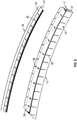
- the elongated profile 35 is arranged in a channel 21 in the building-facing side 17 of the curved frame profile member 13 and is attached to the second end 24 of said tension coil spring 12 by means of the hook member 34 extending through an opening 36 in the curved frame profile member 13; see also Fig. 2 .
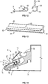
- each straight frame profile member 14 has a rounded outer edge 15 connecting a room-facing side 16 of the straight frame profile member 14 with a building-facing side 17 of the straight frame profile member 14.
- the textile 9 is bent about the rounded outer edges 15 of the straight frame profile members 14, and an edge 18 of the textile 9 is fixed resiliently by means of at least one spring member 19 to the building-facing side 17 of the straight frame profile members 14.
- Each edge 18 of the textile 9 is provided with a bracket 20 arranged in a channel 21 in the building-facing side 17 of the corresponding straight frame profile member 14, and the bracket 20 is spring-biased sideward in the channel 21 by means of the least one spring member 19 in order to tension the textile 9 between the opposed rounded outer edges 15 of the respective straight frame profile members 14.
- the spring member 19 has the form of an elongated flexible hoop. As illustrated in Figs. 14 to 16 , the edge 18 of the textile 9 is fixed in a serrated track 30 extending longitudinally in the bracket 20 in that a retaining member 22 in the form of a spring is pressed into the serrated track 30, thereby pinching the textile edge 18 against the serrated walls of the serrated track 30.
- the distance between the two opposed curved frame profile members 13 is at least 2/3 of, preferably greater than and most preferably at least 4/3 of the distance between the two opposed straight frame profile members 14.
- the above-described arrangement of the first and second spring-biased tensioning mechanisms 6, 7 for tensioning the textile 9 is specifically advantageous for panels having the just mentioned distance between the two opposed curved frame profile members 13, because with such dimensions, by means of already known tensioning systems providing equal tensioning force per unit edge length of the textile in both directions of the textile, it would be very difficult ensuring that the textile forms an intended curvature over the entire length of the peripheral frame between curved frame profile members. Typically, with already known tensioning systems, this would result in the textile flattening out in a central part of the panel.
- each curved frame profile member 13 is made from an extruded metal profile 37, preferably made of aluminium, and each curved frame profile member 13 is provided with a number of lateral slits 38 spaced from each other in the longitudinal direction of the curved frame profile member 13, whereby each lateral slit 38 extends only partly through the extruded metal profile 37.
- a mass produced extruded profile member may easily be formed to any desired curvature of an actual framework of a building panel.
- the flexible extruded metal profile 37 is strengthened by means of a flat, curved metal plate 39 attached to the extruded metal profile 37 along its length.
- the curved metal plate 39 may be attached to the extruded metal profile 37 for instance by means of rivets 56 or any other suitable fastening devices or methods, such as welding.
- a stiff, curved frame profile member 13 suitable for the framework 2 may be obtained from a mass produced extruded profile member.
- the flat, curved metal plate 39 may easily be cut to the desired curvature, for instance by means of a laser cutter, and may compensate for the flexibility of the extruded metal profile 37 provided by the lateral slits. In this way, conveniently, the same type of extruded profile member may be employed for producing both the straight frame profile members 14 and the curved frame profile members 13.
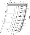
- the framework 2 as partly illustrated in Fig. 8 is assembled from the peripheral frame 5 formed by the four frame profile members 13, 14 described above, as well as two tension profile members 26 of which one is seen in the figure, a number of curved framework profile members 42, and a number of straight framework profile members 43.
- Each tension profile member 26 is arranged parallelly to and at a distance from a curved frame profile member 13 in order to support the first spring-biased tensioning mechanism 6.
- the curved framework profile members 42 are arranged parallelly to and at a distance from a tension profile member 26 in order to support the framework 2 and possibly support a number of insulation mats 8.
- the straight framework profile member or members 43 is/are arranged parallelly to and at a distance from the straight frame profile members 14 in order to support the framework 2 and possibly support a number of insulation mats 8.
- a textile 9 is extended over the room-facing side 3 of the framework 2 between the frame profile members 13, 14, whereby each edge 18 of the textile 9 is attached to a corresponding frame profile member by means of a spring-biased tensioning mechanism 6, 7. Thereby, the extended textile 9 may form a curved surface 10, 11.
- the textile 9 is tensioned to a first tensioning force per unit edge length of the textile in relation to each curved frame profile member 13 by means of the first spring-biased tensioning mechanism 6 and, secondly, the textile 9 is tensioned to a second tensioning force per unit edge length of the textile in relation to each straight frame profile member 14 by means of the second spring-biased tensioning mechanism 7, whereby the first tensioning force per unit edge length of the textile is greater than the second tensioning force per unit edge length of the textile.
- the first tensioning force per unit edge length of the textile provided by the first spring-biased tensioning mechanism 6 is adjusted, preferably steplessly, by means of the first spring-biased tensioning mechanism 6.
- the textile 9 may be a non-woven or woven fabric in the form of a flexible material formed by natural or artificial fibres, yarn or thread.
- the textile 9 is preferably of a material or structure that allows air to diffuse through it.
Landscapes
- Engineering & Computer Science (AREA)
- Architecture (AREA)
- Physics & Mathematics (AREA)
- Electromagnetism (AREA)
- Civil Engineering (AREA)
- Structural Engineering (AREA)
- Building Environments (AREA)
- Tents Or Canopies (AREA)
Priority Applications (1)
| Application Number | Priority Date | Filing Date | Title |
|---|---|---|---|
| PL17726708T PL3625403T3 (pl) | 2017-05-19 | 2017-05-19 | Panel budowlany przystosowany do zamontowania na suficie albo ścianie pomieszczenia i sposób wytwarzania takiego panelu budowlanego |
Applications Claiming Priority (1)
| Application Number | Priority Date | Filing Date | Title |
|---|---|---|---|
| PCT/IB2017/052960 WO2018211313A1 (en) | 2017-05-19 | 2017-05-19 | Building panel adapted to be mounted at a ceiling or wall of a room and method of manufacturing such building panel |
Publications (2)
| Publication Number | Publication Date |
|---|---|
| EP3625403A1 EP3625403A1 (en) | 2020-03-25 |
| EP3625403B1 true EP3625403B1 (en) | 2021-11-03 |
Family
ID=58800870
Family Applications (1)
| Application Number | Title | Priority Date | Filing Date |
|---|---|---|---|
| EP17726708.5A Active EP3625403B1 (en) | 2017-05-19 | 2017-05-19 | Building panel adapted to be mounted at a ceiling or wall of a room and method of manufacturing such building panel |
Country Status (5)
| Country | Link |
|---|---|
| EP (1) | EP3625403B1 (pl) |
| DK (1) | DK3625403T3 (pl) |
| ES (1) | ES2903350T3 (pl) |
| PL (1) | PL3625403T3 (pl) |
| WO (1) | WO2018211313A1 (pl) |
Cited By (2)
| Publication number | Priority date | Publication date | Assignee | Title |
|---|---|---|---|---|
| EP4678841A1 (en) * | 2024-07-11 | 2026-01-14 | Kvadrat Acoustics A/S | Building panel adapted to be mounted at a ceiling or wall of a room and method of manufacturing such building panel |
| WO2026012905A1 (en) * | 2024-07-11 | 2026-01-15 | Kvadrat Acoustics A/S | Building panel adapted to be mounted at a ceiling or wall of a room and method of manufacturing such building panel |
Families Citing this family (1)
| Publication number | Priority date | Publication date | Assignee | Title |
|---|---|---|---|---|
| US10961703B2 (en) * | 2019-08-19 | 2021-03-30 | RAYVA International LLC | Corner assembly for a modular wall overlay system |
Family Cites Families (2)
| Publication number | Priority date | Publication date | Assignee | Title |
|---|---|---|---|---|
| EP1559846B1 (en) | 2004-01-28 | 2009-02-04 | Soft Cells A/S | Panels and systems of such panels for instance for suspended ceilings |
| ITUD20040230A1 (it) * | 2004-12-14 | 2005-03-14 | Tensoforma Trading Srl | Pannello tessile e relativo procedimento di |
-
2017
- 2017-05-19 DK DK17726708.5T patent/DK3625403T3/da active
- 2017-05-19 WO PCT/IB2017/052960 patent/WO2018211313A1/en not_active Ceased
- 2017-05-19 PL PL17726708T patent/PL3625403T3/pl unknown
- 2017-05-19 ES ES17726708T patent/ES2903350T3/es active Active
- 2017-05-19 EP EP17726708.5A patent/EP3625403B1/en active Active
Cited By (2)
| Publication number | Priority date | Publication date | Assignee | Title |
|---|---|---|---|---|
| EP4678841A1 (en) * | 2024-07-11 | 2026-01-14 | Kvadrat Acoustics A/S | Building panel adapted to be mounted at a ceiling or wall of a room and method of manufacturing such building panel |
| WO2026012905A1 (en) * | 2024-07-11 | 2026-01-15 | Kvadrat Acoustics A/S | Building panel adapted to be mounted at a ceiling or wall of a room and method of manufacturing such building panel |
Also Published As
| Publication number | Publication date |
|---|---|
| ES2903350T3 (es) | 2022-04-01 |
| EP3625403A1 (en) | 2020-03-25 |
| WO2018211313A1 (en) | 2018-11-22 |
| PL3625403T3 (pl) | 2022-03-14 |
| DK3625403T3 (da) | 2022-02-07 |
Similar Documents
| Publication | Publication Date | Title |
|---|---|---|
| EP3625403B1 (en) | Building panel adapted to be mounted at a ceiling or wall of a room and method of manufacturing such building panel | |
| EP3802982B1 (en) | Building panel adapted to be mounted at a ceiling or wall of a room and method of manufacturing such building panel | |
| EP3622125B1 (en) | Building panel adapted to be mounted at a ceiling or wall of a room and method of manufacturing such building panel | |
| US6834467B2 (en) | Free form ceiling | |
| JP5813009B2 (ja) | ファサード断熱材 | |
| US12359428B2 (en) | Ceiling system | |
| EP2759651B1 (en) | A suspended ceiling with a noise damper | |
| CA2374434A1 (en) | Elements of stretched false ceiling, use of same for producing false walls and false ceilings | |
| US20150275516A1 (en) | Sound absorbing module and a suspended ceiling comprising the same | |
| KR20190046781A (ko) | 현수식 천장 또는 유사물을 위한 패널 및 현수식 천장 또는 유사물의 프레임 상의 패브릭을 장착하는 방법 | |
| NO337032B1 (no) | Lydabsorberende film | |
| US10961705B2 (en) | Baffle system | |
| EP1939388A2 (en) | Louver | |
| US11946250B2 (en) | Ceiling system and method of installation | |
| US9470039B2 (en) | Architectural mesh framing system | |
| US20150342385A1 (en) | Holding Apparatus for Sheet-Like Elements, Which Holding Apparatus can be Fitted Without Tools | |
| HK40026660B (en) | Building panel adapted to be mounted at a ceiling or wall of a room and method of manufacturing such building panel | |
| EP1612340A1 (en) | Baffle system for a suspended ceiling | |
| WO2003008728A1 (en) | Decorative structure and ceiling system | |
| RU2837028C1 (ru) | Узел фиксации натяжного полотна | |
| US20140138038A1 (en) | Forming curtains | |
| KR101469044B1 (ko) | 루버 | |
| DE202014009761U1 (de) | Lamelle und Decken- und/oder Wandverkleidung hiermit | |
| US7467654B2 (en) | Device for maintaining window coverings or vertically hanging flexible panels | |
| JP2002315668A (ja) | 簾吊り具及び簾の吊設方法 |
Legal Events
| Date | Code | Title | Description |
|---|---|---|---|
| STAA | Information on the status of an ep patent application or granted ep patent |
Free format text: STATUS: UNKNOWN |
|
| STAA | Information on the status of an ep patent application or granted ep patent |
Free format text: STATUS: THE INTERNATIONAL PUBLICATION HAS BEEN MADE |
|
| PUAI | Public reference made under article 153(3) epc to a published international application that has entered the european phase |
Free format text: ORIGINAL CODE: 0009012 |
|
| STAA | Information on the status of an ep patent application or granted ep patent |
Free format text: STATUS: REQUEST FOR EXAMINATION WAS MADE |
|
| 17P | Request for examination filed |
Effective date: 20191218 |
|
| AK | Designated contracting states |
Kind code of ref document: A1 Designated state(s): AL AT BE BG CH CY CZ DE DK EE ES FI FR GB GR HR HU IE IS IT LI LT LU LV MC MK MT NL NO PL PT RO RS SE SI SK SM TR |
|
| AX | Request for extension of the european patent |
Extension state: BA ME |
|
| DAV | Request for validation of the european patent (deleted) | ||
| DAX | Request for extension of the european patent (deleted) | ||
| GRAP | Despatch of communication of intention to grant a patent |
Free format text: ORIGINAL CODE: EPIDOSNIGR1 |
|
| STAA | Information on the status of an ep patent application or granted ep patent |
Free format text: STATUS: GRANT OF PATENT IS INTENDED |
|
| RIC1 | Information provided on ipc code assigned before grant |
Ipc: E04F 13/00 20060101ALN20210111BHEP Ipc: E04B 9/04 20060101AFI20210111BHEP |
|
| INTG | Intention to grant announced |
Effective date: 20210208 |
|
| GRAS | Grant fee paid |
Free format text: ORIGINAL CODE: EPIDOSNIGR3 |
|
| GRAA | (expected) grant |
Free format text: ORIGINAL CODE: 0009210 |
|
| STAA | Information on the status of an ep patent application or granted ep patent |
Free format text: STATUS: THE PATENT HAS BEEN GRANTED |
|
| AK | Designated contracting states |
Kind code of ref document: B1 Designated state(s): AL AT BE BG CH CY CZ DE DK EE ES FI FR GB GR HR HU IE IS IT LI LT LU LV MC MK MT NL NO PL PT RO RS SE SI SK SM TR |
|
| REG | Reference to a national code |
Ref country code: GB Ref legal event code: FG4D |
|
| REG | Reference to a national code |
Ref country code: AT Ref legal event code: REF Ref document number: 1444074 Country of ref document: AT Kind code of ref document: T Effective date: 20211115 Ref country code: CH Ref legal event code: EP |
|
| REG | Reference to a national code |
Ref country code: DE Ref legal event code: R096 Ref document number: 602017048683 Country of ref document: DE |
|
| REG | Reference to a national code |
Ref country code: IE Ref legal event code: FG4D |
|
| REG | Reference to a national code |
Ref country code: FI Ref legal event code: FGE |
|
| REG | Reference to a national code |
Ref country code: DK Ref legal event code: T3 Effective date: 20220202 |
|
| REG | Reference to a national code |
Ref country code: SE Ref legal event code: TRGR |
|
| REG | Reference to a national code |
Ref country code: NL Ref legal event code: FP |
|
| REG | Reference to a national code |
Ref country code: LT Ref legal event code: MG9D |
|
| REG | Reference to a national code |
Ref country code: NO Ref legal event code: T2 Effective date: 20211103 |
|
| REG | Reference to a national code |
Ref country code: ES Ref legal event code: FG2A Ref document number: 2903350 Country of ref document: ES Kind code of ref document: T3 Effective date: 20220401 |
|
| PG25 | Lapsed in a contracting state [announced via postgrant information from national office to epo] |
Ref country code: RS Free format text: LAPSE BECAUSE OF FAILURE TO SUBMIT A TRANSLATION OF THE DESCRIPTION OR TO PAY THE FEE WITHIN THE PRESCRIBED TIME-LIMIT Effective date: 20211103 Ref country code: LT Free format text: LAPSE BECAUSE OF FAILURE TO SUBMIT A TRANSLATION OF THE DESCRIPTION OR TO PAY THE FEE WITHIN THE PRESCRIBED TIME-LIMIT Effective date: 20211103 Ref country code: BG Free format text: LAPSE BECAUSE OF FAILURE TO SUBMIT A TRANSLATION OF THE DESCRIPTION OR TO PAY THE FEE WITHIN THE PRESCRIBED TIME-LIMIT Effective date: 20220203 |
|
| PG25 | Lapsed in a contracting state [announced via postgrant information from national office to epo] |
Ref country code: IS Free format text: LAPSE BECAUSE OF FAILURE TO SUBMIT A TRANSLATION OF THE DESCRIPTION OR TO PAY THE FEE WITHIN THE PRESCRIBED TIME-LIMIT Effective date: 20220303 Ref country code: PT Free format text: LAPSE BECAUSE OF FAILURE TO SUBMIT A TRANSLATION OF THE DESCRIPTION OR TO PAY THE FEE WITHIN THE PRESCRIBED TIME-LIMIT Effective date: 20220303 Ref country code: LV Free format text: LAPSE BECAUSE OF FAILURE TO SUBMIT A TRANSLATION OF THE DESCRIPTION OR TO PAY THE FEE WITHIN THE PRESCRIBED TIME-LIMIT Effective date: 20211103 Ref country code: HR Free format text: LAPSE BECAUSE OF FAILURE TO SUBMIT A TRANSLATION OF THE DESCRIPTION OR TO PAY THE FEE WITHIN THE PRESCRIBED TIME-LIMIT Effective date: 20211103 Ref country code: GR Free format text: LAPSE BECAUSE OF FAILURE TO SUBMIT A TRANSLATION OF THE DESCRIPTION OR TO PAY THE FEE WITHIN THE PRESCRIBED TIME-LIMIT Effective date: 20220204 |
|
| PG25 | Lapsed in a contracting state [announced via postgrant information from national office to epo] |
Ref country code: SM Free format text: LAPSE BECAUSE OF FAILURE TO SUBMIT A TRANSLATION OF THE DESCRIPTION OR TO PAY THE FEE WITHIN THE PRESCRIBED TIME-LIMIT Effective date: 20211103 Ref country code: SK Free format text: LAPSE BECAUSE OF FAILURE TO SUBMIT A TRANSLATION OF THE DESCRIPTION OR TO PAY THE FEE WITHIN THE PRESCRIBED TIME-LIMIT Effective date: 20211103 Ref country code: RO Free format text: LAPSE BECAUSE OF FAILURE TO SUBMIT A TRANSLATION OF THE DESCRIPTION OR TO PAY THE FEE WITHIN THE PRESCRIBED TIME-LIMIT Effective date: 20211103 Ref country code: EE Free format text: LAPSE BECAUSE OF FAILURE TO SUBMIT A TRANSLATION OF THE DESCRIPTION OR TO PAY THE FEE WITHIN THE PRESCRIBED TIME-LIMIT Effective date: 20211103 Ref country code: CZ Free format text: LAPSE BECAUSE OF FAILURE TO SUBMIT A TRANSLATION OF THE DESCRIPTION OR TO PAY THE FEE WITHIN THE PRESCRIBED TIME-LIMIT Effective date: 20211103 |
|
| REG | Reference to a national code |
Ref country code: DE Ref legal event code: R097 Ref document number: 602017048683 Country of ref document: DE |
|
| PLBE | No opposition filed within time limit |
Free format text: ORIGINAL CODE: 0009261 |
|
| STAA | Information on the status of an ep patent application or granted ep patent |
Free format text: STATUS: NO OPPOSITION FILED WITHIN TIME LIMIT |
|
| 26N | No opposition filed |
Effective date: 20220804 |
|
| PG25 | Lapsed in a contracting state [announced via postgrant information from national office to epo] |
Ref country code: AL Free format text: LAPSE BECAUSE OF FAILURE TO SUBMIT A TRANSLATION OF THE DESCRIPTION OR TO PAY THE FEE WITHIN THE PRESCRIBED TIME-LIMIT Effective date: 20211103 |
|
| PG25 | Lapsed in a contracting state [announced via postgrant information from national office to epo] |
Ref country code: SI Free format text: LAPSE BECAUSE OF FAILURE TO SUBMIT A TRANSLATION OF THE DESCRIPTION OR TO PAY THE FEE WITHIN THE PRESCRIBED TIME-LIMIT Effective date: 20211103 |
|
| PG25 | Lapsed in a contracting state [announced via postgrant information from national office to epo] |
Ref country code: MC Free format text: LAPSE BECAUSE OF FAILURE TO SUBMIT A TRANSLATION OF THE DESCRIPTION OR TO PAY THE FEE WITHIN THE PRESCRIBED TIME-LIMIT Effective date: 20211103 Ref country code: LU Free format text: LAPSE BECAUSE OF NON-PAYMENT OF DUE FEES Effective date: 20220519 |
|
| REG | Reference to a national code |
Ref country code: AT Ref legal event code: UEP Ref document number: 1444074 Country of ref document: AT Kind code of ref document: T Effective date: 20211103 |
|
| PG25 | Lapsed in a contracting state [announced via postgrant information from national office to epo] |
Ref country code: MK Free format text: LAPSE BECAUSE OF FAILURE TO SUBMIT A TRANSLATION OF THE DESCRIPTION OR TO PAY THE FEE WITHIN THE PRESCRIBED TIME-LIMIT Effective date: 20211103 Ref country code: CY Free format text: LAPSE BECAUSE OF FAILURE TO SUBMIT A TRANSLATION OF THE DESCRIPTION OR TO PAY THE FEE WITHIN THE PRESCRIBED TIME-LIMIT Effective date: 20211103 |
|
| PG25 | Lapsed in a contracting state [announced via postgrant information from national office to epo] |
Ref country code: HU Free format text: LAPSE BECAUSE OF FAILURE TO SUBMIT A TRANSLATION OF THE DESCRIPTION OR TO PAY THE FEE WITHIN THE PRESCRIBED TIME-LIMIT; INVALID AB INITIO Effective date: 20170519 |
|
| PG25 | Lapsed in a contracting state [announced via postgrant information from national office to epo] |
Ref country code: TR Free format text: LAPSE BECAUSE OF FAILURE TO SUBMIT A TRANSLATION OF THE DESCRIPTION OR TO PAY THE FEE WITHIN THE PRESCRIBED TIME-LIMIT Effective date: 20211103 |
|
| PG25 | Lapsed in a contracting state [announced via postgrant information from national office to epo] |
Ref country code: MT Free format text: LAPSE BECAUSE OF FAILURE TO SUBMIT A TRANSLATION OF THE DESCRIPTION OR TO PAY THE FEE WITHIN THE PRESCRIBED TIME-LIMIT Effective date: 20211103 |
|
| PGFP | Annual fee paid to national office [announced via postgrant information from national office to epo] |
Ref country code: NL Payment date: 20250521 Year of fee payment: 9 |
|
| PGFP | Annual fee paid to national office [announced via postgrant information from national office to epo] |
Ref country code: FI Payment date: 20250526 Year of fee payment: 9 |
|
| PGFP | Annual fee paid to national office [announced via postgrant information from national office to epo] |
Ref country code: PL Payment date: 20250513 Year of fee payment: 9 Ref country code: DE Payment date: 20250521 Year of fee payment: 9 |
|
| PGFP | Annual fee paid to national office [announced via postgrant information from national office to epo] |
Ref country code: GB Payment date: 20250527 Year of fee payment: 9 Ref country code: DK Payment date: 20250526 Year of fee payment: 9 |
|
| PGFP | Annual fee paid to national office [announced via postgrant information from national office to epo] |
Ref country code: NO Payment date: 20250523 Year of fee payment: 9 |
|
| PGFP | Annual fee paid to national office [announced via postgrant information from national office to epo] |
Ref country code: BE Payment date: 20250521 Year of fee payment: 9 Ref country code: IT Payment date: 20250527 Year of fee payment: 9 |
|
| PGFP | Annual fee paid to national office [announced via postgrant information from national office to epo] |
Ref country code: FR Payment date: 20250528 Year of fee payment: 9 |
|
| PGFP | Annual fee paid to national office [announced via postgrant information from national office to epo] |
Ref country code: CH Payment date: 20250601 Year of fee payment: 9 |
|
| PGFP | Annual fee paid to national office [announced via postgrant information from national office to epo] |
Ref country code: AT Payment date: 20250522 Year of fee payment: 9 |
|
| PGFP | Annual fee paid to national office [announced via postgrant information from national office to epo] |
Ref country code: IE Payment date: 20250521 Year of fee payment: 9 |
|
| PGFP | Annual fee paid to national office [announced via postgrant information from national office to epo] |
Ref country code: SE Payment date: 20250521 Year of fee payment: 9 |
|
| PGFP | Annual fee paid to national office [announced via postgrant information from national office to epo] |
Ref country code: ES Payment date: 20250630 Year of fee payment: 9 |