EP3624976B1 - Trenneinrichtung und bearbeitungsmaschine mit trenneinrichtung - Google Patents
Trenneinrichtung und bearbeitungsmaschine mit trenneinrichtung Download PDFInfo
- Publication number
- EP3624976B1 EP3624976B1 EP18725822.3A EP18725822A EP3624976B1 EP 3624976 B1 EP3624976 B1 EP 3624976B1 EP 18725822 A EP18725822 A EP 18725822A EP 3624976 B1 EP3624976 B1 EP 3624976B1
- Authority
- EP
- European Patent Office
- Prior art keywords
- cutting device
- processing machine
- spindle unit
- rotary shaft
- cutting
- Prior art date
- Legal status (The legal status is an assumption and is not a legal conclusion. Google has not performed a legal analysis and makes no representation as to the accuracy of the status listed.)
- Active
Links
Images



Classifications
-
- B—PERFORMING OPERATIONS; TRANSPORTING
- B23—MACHINE TOOLS; METAL-WORKING NOT OTHERWISE PROVIDED FOR
- B23D—PLANING; SLOTTING; SHEARING; BROACHING; SAWING; FILING; SCRAPING; LIKE OPERATIONS FOR WORKING METAL BY REMOVING MATERIAL, NOT OTHERWISE PROVIDED FOR
- B23D47/00—Sawing machines or sawing devices working with circular saw blades, characterised only by constructional features of particular parts
- B23D47/12—Sawing machines or sawing devices working with circular saw blades, characterised only by constructional features of particular parts of drives for circular saw blades
- B23D47/123—Sawing machines or sawing devices working with circular saw blades, characterised only by constructional features of particular parts of drives for circular saw blades acting on the disc of the saw blade
-
- B—PERFORMING OPERATIONS; TRANSPORTING
- B23—MACHINE TOOLS; METAL-WORKING NOT OTHERWISE PROVIDED FOR
- B23D—PLANING; SLOTTING; SHEARING; BROACHING; SAWING; FILING; SCRAPING; LIKE OPERATIONS FOR WORKING METAL BY REMOVING MATERIAL, NOT OTHERWISE PROVIDED FOR
- B23D47/00—Sawing machines or sawing devices working with circular saw blades, characterised only by constructional features of particular parts
- B23D47/12—Sawing machines or sawing devices working with circular saw blades, characterised only by constructional features of particular parts of drives for circular saw blades
-
- B—PERFORMING OPERATIONS; TRANSPORTING
- B23—MACHINE TOOLS; METAL-WORKING NOT OTHERWISE PROVIDED FOR
- B23Q—DETAILS, COMPONENTS, OR ACCESSORIES FOR MACHINE TOOLS, e.g. ARRANGEMENTS FOR COPYING OR CONTROLLING; MACHINE TOOLS IN GENERAL CHARACTERISED BY THE CONSTRUCTION OF PARTICULAR DETAILS OR COMPONENTS; COMBINATIONS OR ASSOCIATIONS OF METAL-WORKING MACHINES, NOT DIRECTED TO A PARTICULAR RESULT
- B23Q5/00—Driving or feeding mechanisms; Control arrangements therefor
- B23Q5/02—Driving main working members
- B23Q5/04—Driving main working members rotary shafts, e.g. working-spindles
- B23Q5/043—Accessories for spindle drives
- B23Q5/045—Angle drives
-
- B—PERFORMING OPERATIONS; TRANSPORTING
- B23—MACHINE TOOLS; METAL-WORKING NOT OTHERWISE PROVIDED FOR
- B23Q—DETAILS, COMPONENTS, OR ACCESSORIES FOR MACHINE TOOLS, e.g. ARRANGEMENTS FOR COPYING OR CONTROLLING; MACHINE TOOLS IN GENERAL CHARACTERISED BY THE CONSTRUCTION OF PARTICULAR DETAILS OR COMPONENTS; COMBINATIONS OR ASSOCIATIONS OF METAL-WORKING MACHINES, NOT DIRECTED TO A PARTICULAR RESULT
- B23Q5/00—Driving or feeding mechanisms; Control arrangements therefor
- B23Q5/02—Driving main working members
- B23Q5/04—Driving main working members rotary shafts, e.g. working-spindles
- B23Q5/043—Accessories for spindle drives
- B23Q5/046—Offset spindle drives
-
- B—PERFORMING OPERATIONS; TRANSPORTING
- B27—WORKING OR PRESERVING WOOD OR SIMILAR MATERIAL; NAILING OR STAPLING MACHINES IN GENERAL
- B27B—SAWS FOR WOOD OR SIMILAR MATERIAL; COMPONENTS OR ACCESSORIES THEREFOR
- B27B5/00—Sawing machines working with circular or cylindrical saw blades; Components or equipment therefor
- B27B5/14—Rim-driven circular saws
-
- B—PERFORMING OPERATIONS; TRANSPORTING
- B27—WORKING OR PRESERVING WOOD OR SIMILAR MATERIAL; NAILING OR STAPLING MACHINES IN GENERAL
- B27B—SAWS FOR WOOD OR SIMILAR MATERIAL; COMPONENTS OR ACCESSORIES THEREFOR
- B27B5/00—Sawing machines working with circular or cylindrical saw blades; Components or equipment therefor
- B27B5/29—Details; Component parts; Accessories
- B27B5/30—Details; Component parts; Accessories for mounting or securing saw blades or saw spindles
Definitions
- the present invention relates to a separating device according to the preamble of claim 1 and a use of a separating device according to the preamble of claim 14.
- This separating device is suitable for processing workpieces, preferably workpieces made of wood, wood-based materials, plastics, insulating materials or composite materials. Such workpieces are preferably plate-shaped workpieces such as those used in the furniture or component industry.
- processing machines which are provided with a separating device in order to divide up plate-shaped workpieces.
- a saw unit is kept in a tool changer, which is changed into a spindle unit of a processing machine when required.
- the circular saw unit is then operated with the machining spindle in order to carry out a cutting operation on a workpiece.
- a device head for a tool device is known, in particular for a circular circular saw or an angle grinder.
- claim 1 provides such a separation device. Further preferred embodiments are listed in the dependent claims and explained in the following description.
- the present invention also provides a processing machine with such a separating device, as well as a use of the separating device.
- the separating device comprises a transmission element which is provided for the eccentric drive of a rotatable separating element, in particular a saw blade, and a rotary shaft which is set up to accommodate a rotary movement for driving the transmission element. It is provided that a section of the rotary shaft can be exchanged in a spindle unit of a processing machine.
- the rotating shaft is thus designed in such a way that it can be exchanged into a spindle unit of a processing machine.
- Such a separating device enables a greater depth of cut with a smaller interfering contour at the same time. In this way, the processing spectrum can be further increased compared to conventional cutting devices.
- the rotary shaft can be exchanged in a hollow shaft cone of a spindle unit.
- the cutting device is a ring saw.
- the hollow shank taper can preferably be an HSK F63 spindle or, alternatively, an E63 spindle, preferably in accordance with DIN69893. It is thus possible to use the separating device in a spindle unit that can also accommodate other tools, for example a milling and / or drilling tool.
- the transmission element is connected to the rotating shaft via a transmission, in particular a gear transmission.
- the separating device comprises a saw ring as a separating element, the separating element being intended for woodworking.
- the separating device is also equipped with a suction device in order to be able to suction off processing residues, in particular wood chips. This makes it easier to clean the separating device, and preferably also a processing machine with which the separating device is used.
- the separating device can be provided with a chip guide plate in order to divert machining residues, in particular wood chips. Thus becomes a extensive contamination of the area around the separating device is avoided.
- the separating device has a multi-part housing, the housing part receiving the receiving device being pivotable relative to the further housing part.
- a multi-part housing makes it easier to replace possible defective elements.
- further processing options can be implemented. For example, inclined cuts can be made (pivoting around the B axis).
- the separating device has an electronic interface in order to be able to receive energy and / or data from the spindle unit. In this way, the flexibility of the separating device is further increased.
- the cutting device can be provided with sensors that record information directly in the area of machining, for example an actual speed of the saw blade, an ambient temperature, a position sensor.
- a pneumatic interface can be provided in order to provide a fluid connection.
- the separating element can be received on the separating device in such a way that an axis of rotation of the separating element extends perpendicular to the axis of rotation of the rotary shaft or parallel to the axis of rotation of the rotary shaft. This means that cuts can be made in a vertical or horizontal direction.
- the present invention relates to a processing machine for processing workpieces made of wood, wood-based materials, plastics or composite materials, which processing machine relates to a spindle unit and a cutting device according to one of the variants described above.
- the rotary shaft of the separating device can be driven by the spindle unit.
- the processing machine comprises a tool store, wherein the separating device can be exchanged in the tool store of the processing machine. Furthermore, the separating device can be removed from the tool storage again. The cutting device is thus integrated into the processing machine.
- the spindle unit can be moved in several translatory and at least one rotary axes, preferably with at least two rotary axes. In this way, in combination with the separating device, an extended range of machining operations is opened up.
- the processing machine has a carrier element, in particular a portal, a boom and a robot arm. Furthermore, a workpiece holder is provided, in particular a workpiece table or one or more consoles.
- the present invention also relates to the use of a separating device in a processing machine for processing wood, wood-based material, plastic, foam material, an insulating mat, a composite material, or a combination thereof, the separating device being a transmission element for eccentric drive of the separating element, in particular a sawing ring, and has a rotary shaft which is set up to receive a rotary movement for driving the transmission element, it being provided that the rotary shaft can be exchanged at least in sections in a spindle unit of a processing machine.
- the rotary shaft can be exchanged in a hollow shaft cone of a spindle unit.
- the cutting device is a ring saw.
- the advantages of the separating device are particularly evident when cutting comparatively soft or flexible materials, such as foam material, an insulating mat (for example, at least in sections made of wood fibers), an insulation board (for example, at least in sections made of polystyrene) or the like.
- the separating device can be used when using the separating device. Furthermore, it is preferred that the separating device is used in combination with an embodiment of the aforementioned processing machine.
- a processing machine 100 is shown schematically, which in the present exemplary embodiment is provided with a portal 102 as an example of a carrier element. Further embodiments relate to machine tools with a boom, a robot arm, or the like are provided.
- the processing machine 100 described in the context of the present embodiment is intended for processing workpieces made of wood, wood-based materials, plastic, foam material, fiber material or a composite material, so that the processing machine 100 is used in the furniture and component industry.
- a spindle unit 50 which can be moved along the portal 102, is attached to the portal 102 of the processing machine 100.
- the movement of the spindle unit 50 in relation to the portal 102 is shown in FIG Fig. 1 indicated by a double arrow (on the spindle unit 50).
- the portal 102 extends over a machine bed 101 and can be moved along this (indicated by a double arrow below the representation of the portal), the machine bed 101 being provided with a support table 101a in the present exemplary embodiment.
- a tool storage 110 is provided adjacent to the machine bed 101, in which various machining tools can be accommodated.
- the position of the tool store 110 is only indicated schematically in the present exemplary embodiment and can be varied as desired depending on the specific application.
- a first embodiment of a separating device 10 according to the invention is shown, which can be exchanged in an interface 51 of the spindle unit 50.
- the spindle unit 50 in Figure 2 is designed as a so-called 5-axis spindle unit.
- the interface 51 of the spindle unit 50 is provided in a receiving body 52 of the spindle unit 50.
- the receiving body 52 is pivotable about an axis A relative to a base section 53 of the spindle unit 50, and the base section 53 is pivotable about an axis C to the attachment section 54 of the spindle unit 50.
- the attachment section 54 of the spindle unit 50 is attached to the portal 102 or a slide that can be moved along the portal.
- the cutting device 10 comprises a receiving device 11 in which a saw blade 30 is received in sections.
- the saw blade 30 is particularly suitable for processing insulating material or for processing wood.
- the saw blade 30 is mounted in the receiving device 11 off-center.
- a transmission element (not shown), which is received in the receiving device 11, can act on the saw blade 30 and drive it to rotate.
- the receiving device 11 is connected to a housing 12 through which a rotating shaft 20 extends and is supported in the housing 12.
- the rotating shaft 20 is rotatable relative to the housing 12.
- An end section of the rotary shaft 20, which protrudes from the housing 12, is designed in such a way that it can be exchanged in an HSK receptacle of the interface 51 of the spindle unit 50.
- a driver pin 13 and receiving pins 14 are provided on the upper section of the housing 12.
- the pins 13, 14 extend parallel to the rotary shaft 20.
- the pins 13, 14 can be inserted into corresponding receptacles in the spindle unit 50, so that the separating device 10 can pivot about an axis that corresponds to the rotary axis of the rotary shaft 20.
- the separating device 10 received by a 5-axis head, as in Fig. 2 and 3 As shown, the separating device 10 itself is usually not rotated relative to the spindle unit 50. By means of the receiving pins 14, however, the separating device 10 is fixed in position on the spindle unit 50 and can be rotated with the spindle unit 50 about the C-axis.
- the recording takes place directly in the C-axis, for example.
- the separating device 10 can be rotated relative to the spindle unit 50.
- the rotating shaft 20 is designed in such a way that it can be exchanged for a hollow shaft taper (HSK F63 or E63).
- the hollow shank taper (HSK) is preferably designed according to DIN 69893. A rotary movement is transmitted to the rotary shaft 20 via the hollow shaft cone, the rotary shaft 20, as already explained, being in engagement with a saw blade via the transmission element.
- Fig. 3 shows another embodiment of the present invention.
- the cutting device is designed in such a way that it can accommodate a saw blade 30 in a horizontal orientation.
- the saw blade 30 extends in a plane which is perpendicular to the axis of rotation of the rotary shaft 20 'of the cutting device 10'.
- the receiving device 11 ′ of the separating device 10 ′ according to the second embodiment in comparison to the first embodiment, is designed to hold the saw blade 30 horizontally.
- the separating device 10 ′ is designed to be identical or similar to those of the separating device 10.
- the separating device 10 ' has a housing 12' from which a driver pin 13 'and receiving pins 14' extend adjacent to the rotary shaft 20 '.
- a further embodiment is also conceivable in which the cutting device can be pivoted in itself, in order to be able to vary the orientation of the saw blade depending on the application.
- Figure 4 shows an example of such a separating device 10 ′′.
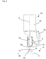
- FIG Figure 4 a third embodiment is shown, which differs from that in FIG Figure 2
- the illustrated embodiment essentially differs in that the separating device 10 ′′ has a multi-part housing, the one receiving device 11 ′′ being pivotable relative to the further housing part 12 ′′.
- the pivotability is shown in FIG Figure 4 illustrated by the additionally provided axis B.
- the separating device 10 has a housing 12 "from which a driver pin 13" and receiving pins 14 "extend adjacent to the rotary shaft 20".
- thicker workpieces can also be machined without having to change a cutting device with a saw blade with an enlarged diameter into the interface 51 of the spindle unit 50 Workpiece are introduced until the workpiece rests against the receiving device 11, 11 ', 11 ".
- the processing spectrum for a cutting device can be further enlarged without having to use a cutting device with a larger saw blade.
- the separating device has a suction device for sucking off processing residues, in particular wood chips, and / or a chip guide plate on the separating device, in particular on the housing 12, 12 ', 12 "of the separating device 10, 10 ', 10 ", is provided in order to divert machining residues, in particular wood chips.
- spindle units can also be provided for receiving the separating device.
- a 3-axis, 4-axis, 5-axis or 6-axis spindle unit can be designed accordingly.
- a processing machine can also have several of these spindle units, the separating device being exchangeable in one or more of these spindle units.
Landscapes
- Engineering & Computer Science (AREA)
- Mechanical Engineering (AREA)
- Life Sciences & Earth Sciences (AREA)
- Wood Science & Technology (AREA)
- Forests & Forestry (AREA)
- Sawing (AREA)
Description
- Die vorliegende Erfindung betrifft eine Trenneinrichtung gemäß dem Oberbegriff des Anspruchs 1 und eine Verwendung einer Trenneinrichtung gemäß dem Oberbegriff des Anspruchs 14. Diese Trenneinrichtung ist geeignet zur Bearbeitung von Werkstücken, bevorzugt Werkstücken aus Holz, Holzwerkstoffen, Kunststoffen, Dämmstoffen oder Verbundwerkstoffen. Bei derartigen Werkstücken handelt es sich bevorzugt um plattenförmige Werkstücke, wie diese im Bereich der Möbel- oder Bauelementeindustrie zum Einsatz kommen.
- Eine solche Trenneinrichtung und eine solche Verwendung sind aus
WO2016/046740A1 bekannt. Im Stand der Technik sind Bearbeitungsmaschinen bekannt, die mit einer Trenneinrichtung versehen sind, um plattenförmige Werkstücke aufzuteilen. Beispielsweise wird in einem Werkzeugwechsler ein Sägeaggregat vorgehalten, das bei Bedarf in eine Spindeleinheit einer Bearbeitungsmaschine eingewechselt wird. Das Kreissägeaggregat wird nachfolgend mit der Bearbeitungsspindel betätigt, um an einem Werkstück eine Schneidbearbeitung durchzuführen. - Allerdings haben konventionelle Sägeaggregate den Nachteil, dass diese einen relativ hohen Platzbedarf erfordern und die Schnitttiefe relativ begrenzt ist.
- Aus der
WO 2014/146794 A1 ist ein Gerätekopf für ein Werkzeuggerät bekannt, insbesondere für eine Ringkreissäge oder einen Winkelschleifer. - Ferner beschreibt die
US 5,193,595 A1 eine Säge für die Holzbearbeitung. - Als weiteres Dokument ist die
WO 2016/046740 A1 bekannt, die eine Maschine zum Bearbeiten von Natursteinplatten, Agglomeraten oder Keramikmaterial zeigt. - Es ist ein Ziel der vorliegenden Erfindung, eine Trenneinrichtung bereitzustellen, mit der auch ein größeres Bearbeitungsspektrum abgedeckt werden kann.
- Der Gegenstand des Anspruchs 1 stellt eine solche Trenneinrichtung bereit. Weitere bevorzugte Ausführungsformen sind in den abhängigen Ansprüchen aufgeführt, sowie in der nachfolgenden Beschreibung erläutert. Ferner stellt die vorliegende Erfindung eine Bearbeitungsmaschine mit einer solchen Trenneinrichtung bereit, sowie eine Verwendung der Trenneinrichtung.
- Die erfindungsgemäße Trenneinrichtung umfasst ein Übertragungselement, das zum außermittigen Antrieb eines drehbaren Trennelements, insbesondere eines Sägeblatts, vorgesehen ist, sowie eine Drehwelle, die eingerichtet ist, eine Drehbewegung zum Antrieb des Übertragungselements aufzunehmen. Dabei ist es vorgesehen, dass ein Abschnitt der Drehwelle in eine Spindeleinheit einer Bearbeitungsmaschine einwechselbar ist. Die Drehwelle ist somit derart ausgestaltet, in eine Spindeleinheit einer Bearbeitungsmaschine eingewechselt zu werden.
- Eine derartige Trenneinrichtung ermöglicht eine größere Schnitttiefe bei gleichzeitig kleinerer Störkontur. Auf diese Weise kann das Bearbeitungsspektrum gegenüber konventionellen Trenneinrichtungen weiter gesteigert werden.
- Ferner ist es vorgesehen, dass die Drehwelle in einen Hohlschaftkegel einer Spindeleinheit einwechselbar ist.
- Erfindungsgemäß ist es vorgesehen, dass die Trenneinrichtung eine Ringsäge ist. Dabei kann es sich bei dem Hohlschaftkegel bevorzugt um eine HSK F63-Spindel oder alternativ eine E63-Spindel, bevorzugt gemäß DIN69893, handeln. Somit ist es möglich, die Trenneinrichtung bei einer Spindeleinheit einzusetzen, die auch andere Werkzeuge aufnehmen kann, bspw. ein Fräs- und/oder Bohrwerkzeug.
- Gemäß einer weiteren Ausführungsform ist es vorgesehen, dass das Übertragungselement über ein Getriebe, insbesondere ein Zahnradgetriebe, mit der Drehwelle in Verbindung steht.
- Neben der Aufnahmevorrichtung zur Aufnahme eines drehbaren Elements ist es gemäß einer bevorzugten Ausführungsform vorgesehen, dass die Trenneinrichtung einen Sägering als Trennelement umfasst, wobei das Trennelement für die Holzbearbeitung vorgesehen ist.
- Gemäß einer bevorzugten Ausführungsform ist die Trenneinrichtung ferner mit einer Absaugeinrichtung ausgestattet, um Bearbeitungsreste, insbesondere Holzspäne, absaugen zu können. Dies erleichtert die Reinigung der Trenneinrichtung, und bevorzugt auch einer Bearbeitungsmaschine, mit der die Trenneinrichtung verwendet wird.
- Als weitere Ausführungsform kann die Trenneinrichtung mit einem Späneleitblech versehen sein, um Bearbeitungsreste, insbesondere Holzspäne, abzuleiten. Somit wird eine großflächige Verunreinigung der Umgebung der Trenneinrichtung vermieden.
- In einer Ausführungsform der vorliegenden Erfindung ist es vorgesehen, dass die Trenneinrichtung ein mehrteiliges Gehäuse aufweist, wobei der die Aufnahmevorrichtung aufnehmende Gehäuseteil relativ zum weiteren Gehäuseteil schwenkbar ist. Durch ein mehrteiliges Gehäuse wird eine einfache Austauschbarkeit möglicher defekte Elemente erleichtert. Im Fall der Schwenkbarkeit zweier Gehäuseteile relativ zueinander können weitere Bearbeitungsmöglichkeiten umgesetzt werden. Beispielsweise können schräge Schnitte durchgeführt werden (Schwenkbarkeit um B-Achse).
- Ferner kann es vorgesehen sein, dass die Trenneinrichtung eine elektronische Schnittstelle aufweist, um Energie und/oder Daten von der Spindeleinheit aufnehmen zu können. Auf diese Weise wird die Flexibilität der Trenneinrichtung weiter gesteigert.
- Beispielsweise kann die Trenneinrichtung mit Sensoren versehen sein, die direkt im Bereich der Bearbeitung Informationen aufnehmen, bspw. eine Ist-Drehzahl des Sägeblatts, eine Umgebungstemperatur, einen Positionssensor.
- Alternativ oder zusätzlich kann eine pneumatische Schnittstelle vorgesehen sein, um eine Fluidverbindung bereitzustellen.
- Gemäß einer Ausführungsform ist es vorgesehen, dass das Trennelement derart an der Trenneinrichtung aufnehmbar ist, dass sich eine Drehachse des Trennelements senkrecht zur Drehachse der Drehwelle oder parallel zur Drehachse der Drehwelle erstreckt. Somit können Schnitte in vertikaler oder horizontaler Richtung durchgeführt werden.
- Ferner betrifft die vorliegende Erfindung eine Bearbeitungsmaschine zur Bearbeitung von Werkstücken aus Holz, Holzwerkstoffen, Kunststoffen oder Verbundwerkstoffen, welche Bearbeitungsmaschine eine Spindeleinheit und eine Trenneinrichtung gemäß einer der zuvor beschriebenen Varianten betrifft. Die Drehwelle der Trenneinrichtung ist durch die Spindeleinheit antreibbar.
- Durch den Einsatz einer solchen Trenneinrichtung in Kombination mit einer Bearbeitungsmaschine, die mit einer Spindeleinheit ausgestattet ist, können die bereits genannten Vorteile, insbesondere die gesteigerte Schnitttiefe, im industriellen Einsatz ausgenutzt werden. Dem Anwender ergeben sich somit vollkommen neue Bearbeitungsmöglichkeiten, wodurch die Einsatzmöglichkeit der Bearbeitungsmaschine gesteigert wird.
- Dabei ist es bevorzugt, dass die Bearbeitungsmaschine einen Werkzeugspeicher umfasst, wobei die Trenneinrichtung in den Werkzeugspeicher der Bearbeitungsmaschine einwechselbar ist. Ferner kann die Trenneinrichtung wieder aus dem Werkzeugspeicher entnommen werden. Somit ist die Trenneinrichtung in die Bearbeitungsmaschine integriert.
- Gemäß einer weiteren Ausführungsform ist es vorgesehen, dass die Spindeleinheit in mehreren translatorischen und zumindest einer rotatorischen Achse, bevorzugt mit zumindest zwei rotatorischen Achsen, bewegbar ist. Auf diese Weise wird in Kombination mit der Trenneinrichtung ein erweitertes Bearbeitungsspektrum erschlossen.
- In einer weiteren Ausführungsform ist es vorgesehen, dass die Bearbeitungsmaschine ein Trägerelement, insbesondere ein Portal, einen Ausleger und einen Roboterarm, aufweist. Ferner ist eine Werkstückaufnahme vorgesehen, insbesondere ein Werkstücktisch oder eine oder mehrere Konsolen.
- Die vorliegende Erfindung betrifft ferner die Verwendung einer Trenneinrichtung in einer Bearbeitungsmaschine zur Bearbeitung von Holz, Holzwerkstoff, Kunststoff, Schaummaterial, einer Dämmmatte, einem Verbundwerkstoff, oder einer Kombination hiervon, wobei die Trenneinrichtung ein Übertragungselement zum außermittigen Antrieb des Trennelements, insbesondere eines Sägerings, und eine Drehwelle aufweist, die eingerichtet ist, eine Drehbewegung zum Antrieb des Übertragungselements aufzunehmen, wobei vorgesehen ist, dass die Drehwelle zumindest abschnittsweise in einer Spindeleinheit einer Bearbeitungsmaschine einwechselbar ist.
- Ferner ist es vorgesehen, dass die Drehwelle in einen Hohlschaftkegel einer Spindeleinheit einwechselbar ist.
- Erfindungsgemäß ist es vorgesehen, dass die Trenneinrichtung eine Ringsäge ist.
- Bei Verwendung einer solchen Trenneinrichtung mit einer Bearbeitungsmaschine ist es möglich, das Bearbeitungsspektrum bei Schneidbearbeitungen zu erweitern. Insbesondere kann eine höhere Schnitttiefe bei relativ kleiner Störkontur erreicht werden.
- Insbesondere bei einer Trennbearbeitung von vergleichsweise weichen oder nachgiebigen Materialien, wie Schaumstoffmaterial, einer Dämmmatte (beispielsweise zumindest abschnittsweise aus Holzfasern), einer Dämmplatte (beispielsweise zumindest abschnittsweise aus Polysterol) oder ähnlichem treten die Vorteile der Trenneinrichtung besonders hervor.
- Bereits genannte Varianten der Trenneinrichtung können bei der Verwendung der Trenneinrichtung zum Einsatz kommen. Ferner ist es bevorzugt, dass die Trenneinrichtung in Kombination mit einer Ausführungsform der zuvor genannten Bearbeitungsmaschine verwendet wird.
-
- Fig. 1
- ist eine schematische Draufsicht auf eine Bearbeitungsmaschine mit einer Spindeleinheit.
- Fig. 2
- zeigt eine erste Ausführungsform einer erfindungsgemäßen Trenneinrichtung mit der Spindeleinheit.
- Fig. 3
- zeigt eine zweite Ausführungsform der erfindungsgemäßen Trenneinrichtung mit der Spindeleinheit.
- Fig. 4
- zeigt eine dritte Ausführungsform der erfindungsgemäßen Trenneinrichtung mit der Spindeleinheit.
- Nachfolgend werden anhand der beigefügten Figuren bevorzugte Ausführungsformen der vorliegenden Erfindung im Detail erläutert. Weitere in diesem Zusammenhang genannte Modifikationen bestimmter Einzelmerkmale können jeweils miteinander kombiniert werden, um weitere Ausführungsformen auszubilden.
- Die nachfolgend beschrieben Ausführungsformen dienen der Veranschaulichung der vorliegenden Erfindung anhand mehrerer Beispiele. Die beschriebenen Ausführungsformen sind deshalb nicht als einschränkend zu betrachten, sondern dienen dem besseren Verständnis der vorliegenden Erfindung.
- In der schematischen Draufsicht von
Fig. 1 wird eine Bearbeitungsmaschine 100 schematisch dargestellt, die im vorliegenden Ausbildungsbeispiel mit einem Portal 102 als einem Beispiel eines Trägerelements versehen ist. Weitere Ausführungsformen betreffen Bearbeitungsmaschinen, die mit einem Ausleger, einem Roboterarm, oder ähnlichem versehen sind. - Die im Rahmen der vorliegenden Ausführungsform beschriebene Bearbeitungsmaschine 100 ist zur Bearbeitung von Werkstücken aus Holz, Holzwerkstoffen, Kunststoff, Schaumstoffmaterial, Fasermaterial oder einem Verbundwerkstoff vorgesehen, so dass die Bearbeitungsmaschine 100 im Bereich der Möbel- und Bauelementeindustrie zum Einsatz kommt.
- Am Portal 102 der Bearbeitungsmaschine 100 ist eine Spindeleinheit 50 angebracht, die entlang des Portals 102 verfahren werden kann. Die Bewegung der Spindeleinheit 50 in Relation zum Portal 102 ist in
Fig. 1 durch einen Doppelpfeil (an der Spindeleinheit 50) angedeutet. - Das Portal 102 erstreckt sich über ein Maschinenbett 101 und ist entlang diesem verfahrbar (durch einen Doppelpfeil unterhalb der Darstellung des Portals angedeutet), wobei im vorliegenden Ausführungsbeispiel das Maschinenbett 101 mit einem Auflagetisch 101a versehen ist.
- Benachbart zum Maschinenbett 101 ist ein Werkzeugspeicher 110 vorgesehen, in dem verschiedene Bearbeitungswerkzeuge aufgenommen werden können. Die Position des Werkzeugspeichers 110 ist im vorliegenden Ausführungsbeispiel lediglich schematisch angedeutet, und kann je nach konkretem Anwendungsfall beliebig variiert werden.
- In
Fig. 2 wird eine erste Ausführungsform einer erfindungsgemäßen Trenneinrichtung 10 dargestellt, die in eine Schnittstelle 51 der Spindeleinheit 50 eingewechselt werden kann. Die Spindeleinheit 50 inFigur 2 ist als eine sogenannte 5-Achsspindeleinheit ausgebildet. - Die Schnittstelle 51 der Spindeleinheit 50 ist in einem Aufnahmekörper 52 der Spindeleinheit 50 vorgesehen. Der Aufnahmekörper 52 ist relativ zu einem Basisabschnitt 53 der Spindeleinheit 50 um eine Achse A schwenkbar, und der Basisabschnitt 53 ist um eine Achse C zum Anbringungsabschnitt 54 der Spindeleinheit 50 schwenkbar. Der Anbringungsabschnitt 54 der Spindeleinheit 50 ist am Portal 102 oder einem entlang des Portals verfahrbaren Schlittens angebracht.
- Die Trenneinrichtung 10 umfasst eine Aufnahmevorrichtung 11, in der ein Sägeblatt 30 abschnittsweise aufgenommen wird. Im vorliegenden Ausführungsbeispiel ist das Sägeblatt 30 insbesondere zur Bearbeitung von Dämmmaterial oder zur Holzbearbeitung geeignet.
- Die Lagerung des Sägeblatts 30 in der Aufnahmevorrichtung 11 erfolgt außermittig. Somit kann ein Übertragungselement (nicht dargestellt), das in der Aufnahmevorrichtung 11 aufgenommen ist, am Sägeblatt 30 angreifen, und dieses drehend antreiben.
- Die Aufnahmevorrichtung 11 ist mit einem Gehäuse 12 verbunden, durch das sich eine Drehwelle 20 erstreckt und im Gehäuse 12 gelagert ist. Die Drehwelle 20 ist relativ zum Gehäuse 12 drehbar. Ein Endabschnitt der Drehwelle 20, der aus dem Gehäuse 12 hervorsteht, ist derart ausgebildet, dass dieser in eine HSK-Aufnahme der Schnittstelle 51 der Spindeleinheit 50 einwechselbar ist.
- Am oberen Abschnitt des Gehäuses 12 sind ein Mitnehmerstift 13 sowie Aufnahmestifte 14 vorgesehen. Die Stifte 13, 14 erstrecken sich parallel zur Drehwelle 20. Die Stifte 13, 14 können in entsprechende Aufnahmen der Spindeleinheit 50 eingeführt werden, so dass eine Schwenkbarkeit der Trenneinrichtung 10 um eine Achse, die der Drehachse der Drehwelle 20 entspricht, sichergestellt wird.
- Ist die Trenneinrichtung 10 durch einen 5-Achskopf aufgenommen, wie in
Fig. 2 und3 dargestellt, so wird das die Trenneinrichtung 10 selbst üblicherweise nicht relativ zur Spindeleinheit 50 gedreht. Durch die Aufnahmestifte 14 wird die Trenneinrichtung 10 jedoch positionsgenau an der Spindeleinheit 50 fixiert und kann mit der Spindeleinheit 50 um die C-Achse gedreht werden. - Im Falle eines 4-Achskopfs (in den Zeichnungen nicht dargestellt) erfolgt die Aufnahme beispielsweise direkt in der C-Achse. Dort kann die Trenneinrichtung 10 relativ zur Spindeleinheit 50 gedreht werden.
- Die Drehwelle 20 ist derart ausgebildet, dass diese in einen Hohlschaftkegel (HSK F63 oder E63) eingewechselt werden kann. Der Hohlschaftkegel (HSK) ist bevorzugt nach DIN 69893 ausgelegt. Über den Hohlschaftkegel wird eine Drehbewegung auf die Drehwelle 20 übertragen, wobei die Drehwelle 20, wie bereits erläutert, über das Übertragungselement mit einem Sägeblatt in Eingriff steht.
- In
Fig. 3 wird eine weitere Ausführungsform der vorliegenden Erfindung dargestellt. Dabei ist die Trenneinrichtung derart ausgebildet, dass diese ein Sägeblatt 30 in einer horizontalen Ausrichtung aufnehmen kann. Das Sägeblatt 30 erstreckt sich in einer Ebene, die senkrecht zur Drehachse der Drehwelle 20' der Trenneinrichtung 10' ausgebildet ist. Entsprechend ist die Aufnahmevorrichtung 11' der Trenneinrichtung 10' gemäß der zweiten Ausführungsform, im Vergleich zur ersten Ausführungsform, zur horizontalen Aufnahme des Sägeblatts 30 ausgebildet. - Weitere Elemente der Trenneinrichtung 10' sind gleich oder ähnlich zu denjenigen der Trenneinrichtung 10 ausgebildet. Insbesondere verfügt die Trenneinrichtung 10' über ein Gehäuse 12', von dem sich ein Mitnehmerstift 13' sowie Aufnahmestifte 14' benachbart zur Drehwelle 20' erstrecken. Neben den in den
Figuren 2-3 dargestellten Ausführungsformen, bei denen das Sägeblatt 30 in der jeweiligen Trenneinrichtung in horizontaler oder vertikaler Ausrichtung aufgenommen wird, ist ferner einer weitere Ausführungsform denkbar, bei der die Trenneinrichtung in sich schwenkbar ist, um somit die Ausrichtung des Sägeblattes je nach Anwendungsfall variieren zu können.Figur 4 zeigt ein Beispiel einer solchen Trenneinrichtung 10". - In
Figur 4 ist eine dritte Ausführungsform dargestellt, die sich gegenüber der inFigur 2 dargestellten Ausführungsform im Wesentlichen dadurch unterscheidet, dass die Trenneinrichtung 10" ein mehrteiliges Gehäuse aufweist, wobei der eine Aufnahmevorrichtung 11" relativ zum weiteren Gehäuseteil 12" schwenkbar ist. Die Schwenkbarkeit wird inFigur 4 durch die zusätzlich bereitgestellte Achse B veranschaulicht. - Weitere Elemente der Trenneinrichtung 10" sind gleich oder ähnlich zu denjenigen der Trenneinrichtung 10 oder 10' ausgebildet. Insbesondere verfügt die Trenneinrichtung 10" über ein Gehäuse 12", von dem sich ein Mitnehmerstift 13" sowie Aufnahmestifte 14" benachbart zur Drehwelle 20" erstrecken.
- Mit den zuvor beschriebenen Trenneinrichtungen 10, 10', 10" können auch dickere Werkstücke bearbeitet werden, ohne eine Trenneinrichtung mit einem Sägeblatt mit vergrößertem Durchmesser in die Schnittstelle 51 der Spindeleinheit 50 einwechseln zu müssen. Das Sägeblatt 30 kann während der Bearbeitung derart tief in ein Werkstück eingeführt werden, bis das Werkstück an der Aufnahmevorrichtung 11, 11', 11" anliegt. Somit steht zusätzlich zum Radius des Sägeblatts 30 eine vergrößerte Schnitttiefe zur Verfügung, bei der zum Durchmesser des Sägeblatts 30 der Abstand zur Aufnahmeeinrichtung 11, 11', 11" hinzukommt. Auf diese Weise kann das Bearbeitungsspektrum für eine Trenneinrichtung weiter vergrößert werden, ohne dabei eine Trenneinrichtung mit einem größeren Sägeblatt einsetzen zu müssen.
- Darüber hinaus sind Modifikationen der beschriebenen Ausführungsformen denkbar, bei denen die Trenneinrichtung über eine Absaugeinrichtung zum Absaugen von Bearbeitungsresten, insbesondere von Holzspänen, verfügt, und/oder ein Späneleitblech an der Trenneinrichtung, insbesondere am Gehäuse 12, 12', 12" der Trenneinrichtung 10, 10', 10", vorgesehen ist, um Bearbeitungsreste, insbesondere Holzspäne, abzuleiten.
- Neben der in den Figuren dargestellten Ausführungsformen einer Spindeleinheit können auch andere Spindeleinheiten zur Aufnahme der Trenneinrichtung vorgesehen sein. Insbesondere kann eine 3-Achs-, 4-Achs-, 5-Achs- oder 6-AchsSpindeleinheit entsprechend ausgebildet sein. Auch kann eine Bearbeitungsmaschine über verschiedene dieser Spindeleinheiten verfügen, wobei die Trenneinrichtung in eine oder mehrere dieser Spindeleinheiten einwechselbar ist.
Claims (14)
- Trenneinrichtung (10, 10', 10"), umfassend:ein Übertragungselement, das zum außermittigen Antrieb eines drehbaren Trennelements (30), insbesondere eines Sägerings, vorgesehen ist, undeine Drehwelle (20, 20', 20"), die eingerichtet ist, eine Drehbewegung zum Antrieb des Übertragungselements aufzunehmen,wobei ein Abschnitt der Drehwelle (20, 20', 20") in eine Schnittstelle (51) einer Spindeleinheit (50) einer Bearbeitungsmaschine (100) einwechselbar ist, undwobei die Drehwelle (20, 20', 20") in einen Hohlschaftkegel einer Spindeleinheit (50) einwechselbar ist,dadurch gekennzeichnet, dass die Trenneinrichtung eine Ringsäge ist.
- Trenneinrichtung (10, 10', 10") gemäß Anspruch 1,
dadurch gekennzeichnet, dass der Hohlschaftkegel eine HSK F63-Spindel ist. - Trenneinrichtung (10, 10', 10") gemäß einem der vorangegangenen Ansprüche, dadurch gekennzeichnet, dass das Übertragungselement über ein Getriebe, insbesondere ein Zahnradgetriebe, mit der Drehwelle (20, 20') in Verbindung steht.
- Trenneinrichtung (10, 10', 10") gemäß einem der vorangegangenen Ansprüche, dadurch gekennzeichnet, dass die Trenneinrichtung als Trennelement einen Sägering für die Holzbearbeitung umfasst.
- Trenneinrichtung (10, 10', 10") gemäß einem der vorangegangenen Ansprüche, dadurch gekennzeichnet, dass die Trenneinrichtung eine Absaugeinrichtung zum Absaugen von Bearbeitungsresten, insbesondere von Holzspänen, umfasst.
- Trenneinrichtung (10, 10', 10") gemäß einem der vorangegangenen Ansprüche, dadurch gekennzeichnet, dass die Trenneinrichtung ein Späneleitblech aufweist, um Bearbeitungsreste, insbesondere Holzspäne, abzuleiten.
- Trenneinrichtung (10") gemäß einem der vorangegangenen Ansprüche, dadurch gekennzeichnet, dass die Trenneinrichtung (10") ein mehrteiliges Gehäuse aufweist, wobei der eine Aufnahmevorrichtung (11") für das Trennelement (30) aufnehmende Gehäuseteil relativ zu einem weiteren Gehäuseteil (12") schwenkbar ist.
- Trenneinrichtung (10, 10', 10") gemäß einem der vorangegangenen Ansprüche, dadurch gekennzeichnet, dass die Trenneinrichtung eine elektronische Schnittstelle aufweist, um Energie und/oder Daten von der Spindeleinheit aufnehmen zu können, und/oder eine pneumatische Schnittstelle aufweist.
- Trenneinrichtung (10, 10', 10") gemäß einem der vorangegangenen Ansprüche, dadurch gekennzeichnet, dass das Trennelement (30) derart an der Trenneinrichtung aufnehmbar ist, dass sich eine Drehachse des Trennelements (30) senkrecht zur Drehachse der Drehwelle (20) oder parallel zur Drehachse der Drehwelle (20') erstreckt.
- Bearbeitungsmaschine (100) zur Bearbeitung von Werkstücken aus Holz oder Holzwerkstoffen, umfassend eine Spindeleinheit (50) sowie eine Trenneinrichtung (10, 10', 10") gemäß einem der vorangegangenen Ansprüche, wobei die Trenneinrichtung (10, 10', 10") über die Spindeleinheit (50) antreibbar ist.
- Bearbeitungsmaschine (100) gemäß Anspruch 10, dadurch gekennzeichnet, dass die Bearbeitungsmaschine einen Werkzeugspeicher (110) umfasst, wobei die Trenneinrichtung (10, 10', 10") in den Werkzeugspeicher der Bearbeitungsmaschine einwechselbar ist.
- Bearbeitungsmaschine (100) gemäß einem der Ansprüche 10-11, dadurch gekennzeichnet, dass die Spindeleinheit (50) in mehreren translatorischen und zumindest einer rotatorischen Achse, bevorzugt zumindest zwei rotatorischen Achsen, bewegbar ist.
- Bearbeitungsmaschine (100) gemäß einem der Ansprüche 10-12, dadurch gekennzeichnet, dass die Bearbeitungsmaschine ein Trägerelement (102), insbesondere ein Portal, einen Ausleger oder einen Roboterarm, und eine Werkstückaufnahme (101, 101a), insbesondere einen Werkstücktisch (101a) oder eine oder mehrere Konsolen, aufweist.
- Verwendung einer Trenneinrichtung (10, 10', 10") in einer Bearbeitungsmaschine (100) zur Bearbeitung von Holz, Holzwerkstoff, Kunststoff, Schaummaterial, einer Dämmmatte, beispielsweise Faserdämmmatte, Dämmplatte, einem Verbundwerkstoff, oder einer Kombination hiervon, wobei die Trenneinrichtung (10, 10', 10") ein Übertragungselement zum außermittigen Antrieb eines drehbares Trennelements (30), insbesondere eines Sägerings, und eine Drehwelle (20, 20', 20") aufweist, die eingerichtet ist, eine Drehbewegung zum Antrieb des Übertragungselements aufzunehmen, wobei vorgesehen ist, dass die Drehwelle (20, 20', 20") zumindest abschnittsweise in eine Schnittstelle (51) der Spindeleinheit (50) einer Bearbeitungsmaschine (100) einwechselbar ist, und wobei die Drehwelle (20, 20', 20") in einen Hohlschaftkegel einer Spindeleinheit (50) einwechselbar ist, dadurch gekennzeichnet, dass die Trenneinrichtung eine Ringsäge ist.
Applications Claiming Priority (2)
| Application Number | Priority Date | Filing Date | Title |
|---|---|---|---|
| DE102017208536.3A DE102017208536A1 (de) | 2017-05-19 | 2017-05-19 | Trenneinrichtung und Bearbeitungsmaschine mit Trenneinrichtung |
| PCT/EP2018/062893 WO2018211008A1 (de) | 2017-05-19 | 2018-05-17 | Trenneinrichtung und bearbeitungsmaschine mit trenneinrichtung |
Publications (2)
| Publication Number | Publication Date |
|---|---|
| EP3624976A1 EP3624976A1 (de) | 2020-03-25 |
| EP3624976B1 true EP3624976B1 (de) | 2021-08-04 |
Family
ID=62200448
Family Applications (1)
| Application Number | Title | Priority Date | Filing Date |
|---|---|---|---|
| EP18725822.3A Active EP3624976B1 (de) | 2017-05-19 | 2018-05-17 | Trenneinrichtung und bearbeitungsmaschine mit trenneinrichtung |
Country Status (5)
| Country | Link |
|---|---|
| US (1) | US20200094333A1 (de) |
| EP (1) | EP3624976B1 (de) |
| CN (1) | CN110621427A (de) |
| DE (1) | DE102017208536A1 (de) |
| WO (1) | WO2018211008A1 (de) |
Families Citing this family (3)
| Publication number | Priority date | Publication date | Assignee | Title |
|---|---|---|---|---|
| JP7041891B2 (ja) * | 2018-04-11 | 2022-03-25 | 国立大学法人千葉大学 | ツールパスの生成方法、ツールパスの生成装置、ツールパスを生成するプログラムおよびプログラムを記録した記録媒体 |
| IT201800010581A1 (it) * | 2018-11-26 | 2020-05-26 | Dario Toncelli | Gruppo per il taglio e la lavorazione di manufatti in materiale lapideo e macchina comprendente tale gruppo di taglio e lavorazione |
| KR102522599B1 (ko) * | 2020-11-26 | 2023-04-18 | 국방과학연구소 | 위치 기반 양방향 키 교환 프로토콜을 제공하는 전자 장치 및 이의 동작 방법 |
Citations (1)
| Publication number | Priority date | Publication date | Assignee | Title |
|---|---|---|---|---|
| WO2016046740A1 (en) * | 2014-09-24 | 2016-03-31 | Dario Toncelli | Tool and machine for working natural stone, agglomerate or ceramic material |
Family Cites Families (11)
| Publication number | Priority date | Publication date | Assignee | Title |
|---|---|---|---|---|
| US5193595A (en) * | 1992-03-16 | 1993-03-16 | Johnson Clyde R | Biscuit joiner attachment for radial arm saw |
| US5529532A (en) * | 1995-07-26 | 1996-06-25 | Desrosiers; Marc | Minature motorized annular hand held dental saw |
| DE29721091U1 (de) * | 1997-06-09 | 1998-01-29 | Elektra Beckum Ag, 49716 Meppen | Tischkreissäge |
| WO2004009278A1 (ja) * | 2002-07-18 | 2004-01-29 | Kazumasa Matsuura | リングソーの駆動装置及びリングソー付き切断装置 |
| US9862120B2 (en) * | 2007-12-13 | 2018-01-09 | Husqvarna Ab | Cutting or sawing machine |
| DE102008017117A1 (de) * | 2008-04-02 | 2009-11-05 | Zimmer, Günther | Werkzeugschwenkaggregat mit mindestens einer fremdverstellten Achse |
| DE102009022784A1 (de) * | 2009-05-19 | 2010-11-25 | Burkhardt Gmbh | Plattenbearbeitungsmaschine von Platten aus Stein, Holz, Metall und/oder deren Ersatzwerkstoffen |
| WO2013167763A1 (es) * | 2012-05-11 | 2013-11-14 | Fundacion Tekniker | Dispositivo de corte |
| DE102013005000B4 (de) * | 2013-03-21 | 2014-11-27 | Rfsdesign Ug (Haftungsbeschränkt) | Gerätekopf für ein Werkzeuggerät, insbesondere für eine Ringkreissäge oder einen Winkelschleifer |
| DE102013222064A1 (de) * | 2013-10-30 | 2015-04-30 | Homag Holzbearbeitungssysteme Gmbh | Aggregatverstellung |
| CN104646752A (zh) * | 2013-11-25 | 2015-05-27 | 苏州宝时得电动工具有限公司 | 一种手持切割机 |
-
2017
- 2017-05-19 DE DE102017208536.3A patent/DE102017208536A1/de not_active Withdrawn
-
2018
- 2018-05-17 EP EP18725822.3A patent/EP3624976B1/de active Active
- 2018-05-17 WO PCT/EP2018/062893 patent/WO2018211008A1/de not_active Ceased
- 2018-05-17 US US16/612,345 patent/US20200094333A1/en not_active Abandoned
- 2018-05-17 CN CN201880032392.6A patent/CN110621427A/zh active Pending
Patent Citations (1)
| Publication number | Priority date | Publication date | Assignee | Title |
|---|---|---|---|---|
| WO2016046740A1 (en) * | 2014-09-24 | 2016-03-31 | Dario Toncelli | Tool and machine for working natural stone, agglomerate or ceramic material |
Also Published As
| Publication number | Publication date |
|---|---|
| CN110621427A (zh) | 2019-12-27 |
| US20200094333A1 (en) | 2020-03-26 |
| DE102017208536A1 (de) | 2018-11-22 |
| EP3624976A1 (de) | 2020-03-25 |
| WO2018211008A1 (de) | 2018-11-22 |
Similar Documents
| Publication | Publication Date | Title |
|---|---|---|
| DE19521846B4 (de) | Numerisch gesteuerte Bearbeitungsmaschine | |
| DE68909889T2 (de) | Werkzeugmaschine für mehrere bearbeitungsarten und zur komplexen bearbeitung von langen werkstücken. | |
| DE19918082B4 (de) | Universal-Werkzeugmaschine | |
| DE19533320C2 (de) | Rundtaktmaschine | |
| DE60005921T2 (de) | Vorrichtung zur Bearbeitung von Bremssätteln und Trägern von Kraftfahrzeug-Scheibenbremsen | |
| DE102009058649A1 (de) | Bohr-Fräsmaschine mit zusätzlichem Drehwerkzeug-Schlitten, Drehaufnahme, Drehwerkzeug und Drehtisch zum Drehen | |
| DE102018002518B4 (de) | Werkzeugmaschinensystem und Bewegungsverfahren | |
| WO2001012370A1 (de) | Tiefbohreinrichtung | |
| DE3502328A1 (de) | Werkzeugmaschine | |
| EP2868431B1 (de) | Aggregatverstellung | |
| EP3639980A1 (de) | Spindelträgerbaugruppe zum einsatz an einer werkzeugmaschine sowie werkzeugmaschine zur spanenden bearbeitung eines werkstücks mit einer derartigen spindelträgerbaugruppe | |
| DE102008029074B4 (de) | Bearbeitungszentrum | |
| WO2018211008A1 (de) | Trenneinrichtung und bearbeitungsmaschine mit trenneinrichtung | |
| DE19904860A1 (de) | Vertikaldrehmaschine | |
| EP3624988B1 (de) | Werkzeugmaschine | |
| DE102005027785B4 (de) | Mehrachsige Drehbearbeitungsvorrichtung und Verfahren zum Drehen eines Werkstücks damit | |
| EP2161099B1 (de) | Schleifmaschine | |
| DE69020870T2 (de) | Mehrspindel-Drehautomat. | |
| EP2420347B1 (de) | Bearbeitungsvorrichtung mit schwenkbarem Bearbeitungskopf | |
| DE102007010667B4 (de) | Werkzeugmaschine mit Werkzeugtisch | |
| EP3197636B1 (de) | Bearbeitungsvorrichtung | |
| DE10140940B4 (de) | Drehmaschine | |
| EP2743047A1 (de) | Universalbearbeitungseinheit | |
| WO2002076663A1 (de) | Werkzeugmaschine, insbesondere abdachmaschine | |
| EP0354393A2 (de) | Endenbearbeitungsmaschine |
Legal Events
| Date | Code | Title | Description |
|---|---|---|---|
| STAA | Information on the status of an ep patent application or granted ep patent |
Free format text: STATUS: UNKNOWN |
|
| STAA | Information on the status of an ep patent application or granted ep patent |
Free format text: STATUS: THE INTERNATIONAL PUBLICATION HAS BEEN MADE |
|
| PUAI | Public reference made under article 153(3) epc to a published international application that has entered the european phase |
Free format text: ORIGINAL CODE: 0009012 |
|
| STAA | Information on the status of an ep patent application or granted ep patent |
Free format text: STATUS: REQUEST FOR EXAMINATION WAS MADE |
|
| 17P | Request for examination filed |
Effective date: 20190924 |
|
| AK | Designated contracting states |
Kind code of ref document: A1 Designated state(s): AL AT BE BG CH CY CZ DE DK EE ES FI FR GB GR HR HU IE IS IT LI LT LU LV MC MK MT NL NO PL PT RO RS SE SI SK SM TR |
|
| AX | Request for extension of the european patent |
Extension state: BA ME |
|
| DAV | Request for validation of the european patent (deleted) | ||
| DAX | Request for extension of the european patent (deleted) | ||
| STAA | Information on the status of an ep patent application or granted ep patent |
Free format text: STATUS: EXAMINATION IS IN PROGRESS |
|
| 17Q | First examination report despatched |
Effective date: 20201215 |
|
| GRAP | Despatch of communication of intention to grant a patent |
Free format text: ORIGINAL CODE: EPIDOSNIGR1 |
|
| STAA | Information on the status of an ep patent application or granted ep patent |
Free format text: STATUS: GRANT OF PATENT IS INTENDED |
|
| INTG | Intention to grant announced |
Effective date: 20210324 |
|
| GRAS | Grant fee paid |
Free format text: ORIGINAL CODE: EPIDOSNIGR3 |
|
| GRAA | (expected) grant |
Free format text: ORIGINAL CODE: 0009210 |
|
| STAA | Information on the status of an ep patent application or granted ep patent |
Free format text: STATUS: THE PATENT HAS BEEN GRANTED |
|
| AK | Designated contracting states |
Kind code of ref document: B1 Designated state(s): AL AT BE BG CH CY CZ DE DK EE ES FI FR GB GR HR HU IE IS IT LI LT LU LV MC MK MT NL NO PL PT RO RS SE SI SK SM TR |
|
| REG | Reference to a national code |
Ref country code: GB Ref legal event code: FG4D Free format text: NOT ENGLISH |
|
| REG | Reference to a national code |
Ref country code: AT Ref legal event code: REF Ref document number: 1416468 Country of ref document: AT Kind code of ref document: T Effective date: 20210815 |
|
| REG | Reference to a national code |
Ref country code: CH Ref legal event code: EP |
|
| REG | Reference to a national code |
Ref country code: DE Ref legal event code: R096 Ref document number: 502018006428 Country of ref document: DE |
|
| REG | Reference to a national code |
Ref country code: IE Ref legal event code: FG4D Free format text: LANGUAGE OF EP DOCUMENT: GERMAN |
|
| REG | Reference to a national code |
Ref country code: LT Ref legal event code: MG9D |
|
| REG | Reference to a national code |
Ref country code: NL Ref legal event code: MP Effective date: 20210804 |
|
| PG25 | Lapsed in a contracting state [announced via postgrant information from national office to epo] |
Ref country code: LT Free format text: LAPSE BECAUSE OF FAILURE TO SUBMIT A TRANSLATION OF THE DESCRIPTION OR TO PAY THE FEE WITHIN THE PRESCRIBED TIME-LIMIT Effective date: 20210804 Ref country code: BG Free format text: LAPSE BECAUSE OF FAILURE TO SUBMIT A TRANSLATION OF THE DESCRIPTION OR TO PAY THE FEE WITHIN THE PRESCRIBED TIME-LIMIT Effective date: 20211104 Ref country code: NO Free format text: LAPSE BECAUSE OF FAILURE TO SUBMIT A TRANSLATION OF THE DESCRIPTION OR TO PAY THE FEE WITHIN THE PRESCRIBED TIME-LIMIT Effective date: 20211104 Ref country code: PT Free format text: LAPSE BECAUSE OF FAILURE TO SUBMIT A TRANSLATION OF THE DESCRIPTION OR TO PAY THE FEE WITHIN THE PRESCRIBED TIME-LIMIT Effective date: 20211206 Ref country code: HR Free format text: LAPSE BECAUSE OF FAILURE TO SUBMIT A TRANSLATION OF THE DESCRIPTION OR TO PAY THE FEE WITHIN THE PRESCRIBED TIME-LIMIT Effective date: 20210804 Ref country code: ES Free format text: LAPSE BECAUSE OF FAILURE TO SUBMIT A TRANSLATION OF THE DESCRIPTION OR TO PAY THE FEE WITHIN THE PRESCRIBED TIME-LIMIT Effective date: 20210804 Ref country code: FI Free format text: LAPSE BECAUSE OF FAILURE TO SUBMIT A TRANSLATION OF THE DESCRIPTION OR TO PAY THE FEE WITHIN THE PRESCRIBED TIME-LIMIT Effective date: 20210804 Ref country code: SE Free format text: LAPSE BECAUSE OF FAILURE TO SUBMIT A TRANSLATION OF THE DESCRIPTION OR TO PAY THE FEE WITHIN THE PRESCRIBED TIME-LIMIT Effective date: 20210804 Ref country code: RS Free format text: LAPSE BECAUSE OF FAILURE TO SUBMIT A TRANSLATION OF THE DESCRIPTION OR TO PAY THE FEE WITHIN THE PRESCRIBED TIME-LIMIT Effective date: 20210804 |
|
| PG25 | Lapsed in a contracting state [announced via postgrant information from national office to epo] |
Ref country code: PL Free format text: LAPSE BECAUSE OF FAILURE TO SUBMIT A TRANSLATION OF THE DESCRIPTION OR TO PAY THE FEE WITHIN THE PRESCRIBED TIME-LIMIT Effective date: 20210804 Ref country code: LV Free format text: LAPSE BECAUSE OF FAILURE TO SUBMIT A TRANSLATION OF THE DESCRIPTION OR TO PAY THE FEE WITHIN THE PRESCRIBED TIME-LIMIT Effective date: 20210804 Ref country code: GR Free format text: LAPSE BECAUSE OF FAILURE TO SUBMIT A TRANSLATION OF THE DESCRIPTION OR TO PAY THE FEE WITHIN THE PRESCRIBED TIME-LIMIT Effective date: 20211105 |
|
| PG25 | Lapsed in a contracting state [announced via postgrant information from national office to epo] |
Ref country code: NL Free format text: LAPSE BECAUSE OF FAILURE TO SUBMIT A TRANSLATION OF THE DESCRIPTION OR TO PAY THE FEE WITHIN THE PRESCRIBED TIME-LIMIT Effective date: 20210804 |
|
| PG25 | Lapsed in a contracting state [announced via postgrant information from national office to epo] |
Ref country code: DK Free format text: LAPSE BECAUSE OF FAILURE TO SUBMIT A TRANSLATION OF THE DESCRIPTION OR TO PAY THE FEE WITHIN THE PRESCRIBED TIME-LIMIT Effective date: 20210804 |
|
| REG | Reference to a national code |
Ref country code: DE Ref legal event code: R097 Ref document number: 502018006428 Country of ref document: DE |
|
| PG25 | Lapsed in a contracting state [announced via postgrant information from national office to epo] |
Ref country code: SM Free format text: LAPSE BECAUSE OF FAILURE TO SUBMIT A TRANSLATION OF THE DESCRIPTION OR TO PAY THE FEE WITHIN THE PRESCRIBED TIME-LIMIT Effective date: 20210804 Ref country code: SK Free format text: LAPSE BECAUSE OF FAILURE TO SUBMIT A TRANSLATION OF THE DESCRIPTION OR TO PAY THE FEE WITHIN THE PRESCRIBED TIME-LIMIT Effective date: 20210804 Ref country code: RO Free format text: LAPSE BECAUSE OF FAILURE TO SUBMIT A TRANSLATION OF THE DESCRIPTION OR TO PAY THE FEE WITHIN THE PRESCRIBED TIME-LIMIT Effective date: 20210804 Ref country code: EE Free format text: LAPSE BECAUSE OF FAILURE TO SUBMIT A TRANSLATION OF THE DESCRIPTION OR TO PAY THE FEE WITHIN THE PRESCRIBED TIME-LIMIT Effective date: 20210804 Ref country code: CZ Free format text: LAPSE BECAUSE OF FAILURE TO SUBMIT A TRANSLATION OF THE DESCRIPTION OR TO PAY THE FEE WITHIN THE PRESCRIBED TIME-LIMIT Effective date: 20210804 Ref country code: AL Free format text: LAPSE BECAUSE OF FAILURE TO SUBMIT A TRANSLATION OF THE DESCRIPTION OR TO PAY THE FEE WITHIN THE PRESCRIBED TIME-LIMIT Effective date: 20210804 |
|
| PLBE | No opposition filed within time limit |
Free format text: ORIGINAL CODE: 0009261 |
|
| STAA | Information on the status of an ep patent application or granted ep patent |
Free format text: STATUS: NO OPPOSITION FILED WITHIN TIME LIMIT |
|
| 26N | No opposition filed |
Effective date: 20220506 |
|
| PG25 | Lapsed in a contracting state [announced via postgrant information from national office to epo] |
Ref country code: SI Free format text: LAPSE BECAUSE OF FAILURE TO SUBMIT A TRANSLATION OF THE DESCRIPTION OR TO PAY THE FEE WITHIN THE PRESCRIBED TIME-LIMIT Effective date: 20210804 |
|
| REG | Reference to a national code |
Ref country code: CH Ref legal event code: PL |
|
| REG | Reference to a national code |
Ref country code: BE Ref legal event code: MM Effective date: 20220531 |
|
| GBPC | Gb: european patent ceased through non-payment of renewal fee |
Effective date: 20220517 |
|
| PG25 | Lapsed in a contracting state [announced via postgrant information from national office to epo] |
Ref country code: MC Free format text: LAPSE BECAUSE OF FAILURE TO SUBMIT A TRANSLATION OF THE DESCRIPTION OR TO PAY THE FEE WITHIN THE PRESCRIBED TIME-LIMIT Effective date: 20210804 Ref country code: LU Free format text: LAPSE BECAUSE OF NON-PAYMENT OF DUE FEES Effective date: 20220517 Ref country code: LI Free format text: LAPSE BECAUSE OF NON-PAYMENT OF DUE FEES Effective date: 20220531 Ref country code: CH Free format text: LAPSE BECAUSE OF NON-PAYMENT OF DUE FEES Effective date: 20220531 |
|
| PG25 | Lapsed in a contracting state [announced via postgrant information from national office to epo] |
Ref country code: IE Free format text: LAPSE BECAUSE OF NON-PAYMENT OF DUE FEES Effective date: 20220517 Ref country code: FR Free format text: LAPSE BECAUSE OF NON-PAYMENT OF DUE FEES Effective date: 20220531 |
|
| PG25 | Lapsed in a contracting state [announced via postgrant information from national office to epo] |
Ref country code: GB Free format text: LAPSE BECAUSE OF NON-PAYMENT OF DUE FEES Effective date: 20220517 Ref country code: BE Free format text: LAPSE BECAUSE OF NON-PAYMENT OF DUE FEES Effective date: 20220531 |
|
| P01 | Opt-out of the competence of the unified patent court (upc) registered |
Effective date: 20230529 |
|
| PG25 | Lapsed in a contracting state [announced via postgrant information from national office to epo] |
Ref country code: MK Free format text: LAPSE BECAUSE OF FAILURE TO SUBMIT A TRANSLATION OF THE DESCRIPTION OR TO PAY THE FEE WITHIN THE PRESCRIBED TIME-LIMIT Effective date: 20210804 Ref country code: CY Free format text: LAPSE BECAUSE OF FAILURE TO SUBMIT A TRANSLATION OF THE DESCRIPTION OR TO PAY THE FEE WITHIN THE PRESCRIBED TIME-LIMIT Effective date: 20210804 |
|
| PG25 | Lapsed in a contracting state [announced via postgrant information from national office to epo] |
Ref country code: HU Free format text: LAPSE BECAUSE OF FAILURE TO SUBMIT A TRANSLATION OF THE DESCRIPTION OR TO PAY THE FEE WITHIN THE PRESCRIBED TIME-LIMIT; INVALID AB INITIO Effective date: 20180517 |
|
| PG25 | Lapsed in a contracting state [announced via postgrant information from national office to epo] |
Ref country code: MT Free format text: LAPSE BECAUSE OF FAILURE TO SUBMIT A TRANSLATION OF THE DESCRIPTION OR TO PAY THE FEE WITHIN THE PRESCRIBED TIME-LIMIT Effective date: 20210804 |
|
| PGFP | Annual fee paid to national office [announced via postgrant information from national office to epo] |
Ref country code: DE Payment date: 20250520 Year of fee payment: 8 |
|
| PGFP | Annual fee paid to national office [announced via postgrant information from national office to epo] |
Ref country code: IT Payment date: 20250522 Year of fee payment: 8 |
|
| PGFP | Annual fee paid to national office [announced via postgrant information from national office to epo] |
Ref country code: AT Payment date: 20250520 Year of fee payment: 8 |
|
| PG25 | Lapsed in a contracting state [announced via postgrant information from national office to epo] |
Ref country code: TR Free format text: LAPSE BECAUSE OF FAILURE TO SUBMIT A TRANSLATION OF THE DESCRIPTION OR TO PAY THE FEE WITHIN THE PRESCRIBED TIME-LIMIT Effective date: 20210804 |