EP3624531A1 - Procédé de transmission de srs et dispositif associé - Google Patents
Procédé de transmission de srs et dispositif associé Download PDFInfo
- Publication number
- EP3624531A1 EP3624531A1 EP18900436.9A EP18900436A EP3624531A1 EP 3624531 A1 EP3624531 A1 EP 3624531A1 EP 18900436 A EP18900436 A EP 18900436A EP 3624531 A1 EP3624531 A1 EP 3624531A1
- Authority
- EP
- European Patent Office
- Prior art keywords
- srs
- srs resource
- uplink bwp
- parameter configuration
- configuration
- Prior art date
- Legal status (The legal status is an assumption and is not a legal conclusion. Google has not performed a legal analysis and makes no representation as to the accuracy of the status listed.)
- Withdrawn
Links
Images

Classifications
-
- H—ELECTRICITY
- H04—ELECTRIC COMMUNICATION TECHNIQUE
- H04L—TRANSMISSION OF DIGITAL INFORMATION, e.g. TELEGRAPHIC COMMUNICATION
- H04L25/00—Baseband systems
- H04L25/02—Details ; arrangements for supplying electrical power along data transmission lines
- H04L25/0202—Channel estimation
- H04L25/0224—Channel estimation using sounding signals
- H04L25/0226—Channel estimation using sounding signals sounding signals per se
-
- H—ELECTRICITY
- H04—ELECTRIC COMMUNICATION TECHNIQUE
- H04L—TRANSMISSION OF DIGITAL INFORMATION, e.g. TELEGRAPHIC COMMUNICATION
- H04L5/00—Arrangements affording multiple use of the transmission path
- H04L5/003—Arrangements for allocating sub-channels of the transmission path
- H04L5/0048—Allocation of pilot signals, i.e. of signals known to the receiver
-
- H—ELECTRICITY
- H04—ELECTRIC COMMUNICATION TECHNIQUE
- H04L—TRANSMISSION OF DIGITAL INFORMATION, e.g. TELEGRAPHIC COMMUNICATION
- H04L1/00—Arrangements for detecting or preventing errors in the information received
- H04L1/0001—Systems modifying transmission characteristics according to link quality, e.g. power backoff
- H04L1/0023—Systems modifying transmission characteristics according to link quality, e.g. power backoff characterised by the signalling
- H04L1/0026—Transmission of channel quality indication
-
- H—ELECTRICITY
- H04—ELECTRIC COMMUNICATION TECHNIQUE
- H04L—TRANSMISSION OF DIGITAL INFORMATION, e.g. TELEGRAPHIC COMMUNICATION
- H04L5/00—Arrangements affording multiple use of the transmission path
- H04L5/003—Arrangements for allocating sub-channels of the transmission path
- H04L5/0048—Allocation of pilot signals, i.e. of signals known to the receiver
- H04L5/0051—Allocation of pilot signals, i.e. of signals known to the receiver of dedicated pilots, i.e. pilots destined for a single user or terminal
-
- H—ELECTRICITY
- H04—ELECTRIC COMMUNICATION TECHNIQUE
- H04L—TRANSMISSION OF DIGITAL INFORMATION, e.g. TELEGRAPHIC COMMUNICATION
- H04L5/00—Arrangements affording multiple use of the transmission path
- H04L5/0091—Signaling for the administration of the divided path
- H04L5/0092—Indication of how the channel is divided
-
- H—ELECTRICITY
- H04—ELECTRIC COMMUNICATION TECHNIQUE
- H04L—TRANSMISSION OF DIGITAL INFORMATION, e.g. TELEGRAPHIC COMMUNICATION
- H04L5/00—Arrangements affording multiple use of the transmission path
- H04L5/0091—Signaling for the administration of the divided path
- H04L5/0094—Indication of how sub-channels of the path are allocated
-
- H—ELECTRICITY
- H04—ELECTRIC COMMUNICATION TECHNIQUE
- H04L—TRANSMISSION OF DIGITAL INFORMATION, e.g. TELEGRAPHIC COMMUNICATION
- H04L5/00—Arrangements affording multiple use of the transmission path
- H04L5/0091—Signaling for the administration of the divided path
- H04L5/0096—Indication of changes in allocation
- H04L5/0098—Signalling of the activation or deactivation of component carriers, subcarriers or frequency bands
-
- H—ELECTRICITY
- H04—ELECTRIC COMMUNICATION TECHNIQUE
- H04W—WIRELESS COMMUNICATION NETWORKS
- H04W52/00—Power management, e.g. TPC [Transmission Power Control], power saving or power classes
- H04W52/04—TPC
- H04W52/06—TPC algorithms
- H04W52/14—Separate analysis of uplink or downlink
- H04W52/146—Uplink power control
-
- H—ELECTRICITY
- H04—ELECTRIC COMMUNICATION TECHNIQUE
- H04W—WIRELESS COMMUNICATION NETWORKS
- H04W52/00—Power management, e.g. TPC [Transmission Power Control], power saving or power classes
- H04W52/04—TPC
- H04W52/30—TPC using constraints in the total amount of available transmission power
- H04W52/32—TPC of broadcast or control channels
- H04W52/325—Power control of control or pilot channels
-
- H—ELECTRICITY
- H04—ELECTRIC COMMUNICATION TECHNIQUE
- H04W—WIRELESS COMMUNICATION NETWORKS
- H04W56/00—Synchronisation arrangements
- H04W56/001—Synchronization between nodes
-
- H—ELECTRICITY
- H04—ELECTRIC COMMUNICATION TECHNIQUE
- H04W—WIRELESS COMMUNICATION NETWORKS
- H04W72/00—Local resource management
- H04W72/04—Wireless resource allocation
-
- H—ELECTRICITY
- H04—ELECTRIC COMMUNICATION TECHNIQUE
- H04W—WIRELESS COMMUNICATION NETWORKS
- H04W72/00—Local resource management
- H04W72/04—Wireless resource allocation
- H04W72/044—Wireless resource allocation based on the type of the allocated resource
- H04W72/0453—Resources in frequency domain, e.g. a carrier in FDMA
-
- H—ELECTRICITY
- H04—ELECTRIC COMMUNICATION TECHNIQUE
- H04W—WIRELESS COMMUNICATION NETWORKS
- H04W72/00—Local resource management
- H04W72/04—Wireless resource allocation
- H04W72/044—Wireless resource allocation based on the type of the allocated resource
- H04W72/0473—Wireless resource allocation based on the type of the allocated resource the resource being transmission power
-
- H—ELECTRICITY
- H04—ELECTRIC COMMUNICATION TECHNIQUE
- H04W—WIRELESS COMMUNICATION NETWORKS
- H04W72/00—Local resource management
- H04W72/20—Control channels or signalling for resource management
- H04W72/21—Control channels or signalling for resource management in the uplink direction of a wireless link, i.e. towards the network
-
- H—ELECTRICITY
- H04—ELECTRIC COMMUNICATION TECHNIQUE
- H04W—WIRELESS COMMUNICATION NETWORKS
- H04W72/00—Local resource management
- H04W72/20—Control channels or signalling for resource management
- H04W72/23—Control channels or signalling for resource management in the downlink direction of a wireless link, i.e. towards a terminal
-
- H—ELECTRICITY
- H04—ELECTRIC COMMUNICATION TECHNIQUE
- H04W—WIRELESS COMMUNICATION NETWORKS
- H04W80/00—Wireless network protocols or protocol adaptations to wireless operation
- H04W80/08—Upper layer protocols
Definitions
- the disclosure relates to the technical field of communications, and particularly to a method and device for Sounding Reference Signal (SRS) transmission.
- SRS Sounding Reference Signal
- a carrier may include multiple Bandwidth components (BWPs).
- BWPs Bandwidth components
- the specific BWP presently activated for the UE is indicated through Downlink Control Information (DCI), and the BWP for transmission at the UE may be dynamically switched in multiple BWPs in a carrier.
- DCI Downlink Control Information
- SRS transmission may be dynamically switched on multiple BWPs, how to configure transmission of an SRS is a technical problem to be solved.
- Embodiments of the disclosure provide a method and device for SRS transmission, which are adopted to improve the flexibility of SRS transmission.
- the embodiments of the disclosure provide a method for SRS transmission, which may include the following operations.
- UE determines an uplink BWP which is active.
- the UE determines an SRS parameter configuration corresponding to the uplink BWP which is active.
- the UE transmits an SRS on the uplink BWP according to the SRS parameter configuration.
- the embodiments of the disclosure provide UE, which may include a processing unit and a communication unit.
- the processing unit may be configured to determine an active uplink BWP.
- the processing unit may further be configured to determine an SRS parameter configuration corresponding to the active uplink BWP.
- the processing unit may further be configured to transmit an SRS on the uplink BWP through the communication unit according to the SRS parameter configuration.
- the embodiments of the disclosure provide UE, which may include one or more processors, one or more memories, one or more transceivers and one or more programs, the one or more programs being stored in the memory and configured to be executed by the one or more processors and the programs including instructions configured to execute the steps in the method according to the first aspect.
- the embodiments of the disclosure provide a computer-readable storage medium, which may store a computer program configured for electronic data exchange, the computer program enabling a computer to execute part or all of the steps described in any method according to the first aspect.
- the embodiments of the disclosure provide a computer program product, which includes a non-transitory computer-readable storage medium storing a computer program.
- the computer program may be operated to enable a computer to execute part or all of the steps described in any method according to the first aspect.
- the computer program product may be a software installation package.
- a network device may set a set of SRS parameter configurations for each BWP of the UE; then, under the condition that the UE is dynamically switched to a certain BWP for SRS transmission, the UE may determine the SRS parameter configuration corresponding to the BWP as the SRS parameter configuration for SRS transmission; and finally, the UE transmits the SRS on the BWP on the basis of the SRS parameter configuration corresponding to the BWP.
- different SRS parameter configurations may be adopted for SRS transmission on different BWPs, and SRS transmission flexibility is further improved.
- FIG. 1 illustrates a wireless communication system involved in the disclosure.
- the wireless communication system is not limited to a Long Term Evolution (LTE) system, but may also be a future evolved 5th Generation (5G) system, an NR system, a Machine to Machine (M2M) system and the like.
- LTE Long Term Evolution
- 5G 5th Generation
- NR NR
- M2M Machine to Machine
- the wireless communication system 100 may include one or more network devices 101 and one or more UEs 102.
- the network device 101 may be a base station, and the base station may be configured to communicate with one or more UEs, and may also be configured to communicate with one or more base stations with part of UE functions (for example, communication between a macro NodeB and a micro NodeB like an Access Point (AP)).
- the base station may be a Base Transceiver Station (BTS) in a Time Division Synchronous Code Division Multiple Access (TD-SCDMA) system, or may also be an Evolutional Node B (eNB) in the LTE system or a base station in a 5G system or in an NR system.
- the base station may also be an AP, a Transmission Reception Point (TRP), a Central Unit (CU) or another network entity, and may include some or all functions of the above network entities.
- TRP Transmission Reception Point
- CU Central Unit
- the UE 102 may be distributed in the whole wireless communication system 100, which may be static or mobile.
- the UE 102 may be a mobile device, a mobile station, a mobile unit, an M2M terminal, a wireless unit, a remote unit, a user agent, a mobile client and the like.
- the network device 101 may be configured to communicate with the UE 102 through a wireless interface 103 under control of a network device controller (not shown).
- the network device controller may be a part of a core network, or may also be integrated into the network device 101.
- a network device 101 may also directly or indirectly communicate with another network device 101 through a backhaul interface 104 (for example, an X2 interface).
- a carrier may include multiple BWPs.
- For UE 102 only one uplink BWP may be activated for uplink transmission at a moment, while only one downlink BWP may be activated for downlink transmission at a moment.
- the specific BWP presently activated for the UE 102 is indicated by the network device 101 through DCI, and the BWP for transmission at the UE 102 may be dynamically switched in multiple BWPs in a carrier. If SRS transmission may be dynamically switched on multiple BWPs, how to configure transmission of an SRS is a technical problem to be solved.
- the network device 101 may set a set of SRS parameter configurations for each BWP of the UE 102 at first; then, under the condition that the UE 102 is dynamically switched to a BWP for SRS transmission, the UE 102 may determine the SRS parameter configuration corresponding to the BWP as an SRS parameter configuration used for SRS transmission; and finally, the UE 102 transmits an SRS on the BWP on the basis of the SRS parameter configuration corresponding to the BWP.
- different SRS parameter configurations may be adopted for SRS transmission on different BWPs, and the flexibility of SRS transmission is further improved.
- the wireless communication system 100 shown in FIG. 1 is only adopted to describe the technical solutions of the disclosure more clearly but not intended to limit the disclosure.
- Those of ordinary skill in the art should know that, along with evolution of a network architecture and emergence of a new service scenario, the technical solutions provided in the disclosure can also be applied to similar technical problems.
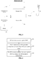
- FIG. 2 illustrates UE 200 according to some embodiments of the disclosure.
- the UE 200 may include one or more UE processors 201, a memory 202, a communication interface 203, a receiver 205, a transmitter 206, a coupler 207, an antenna 208, a user interface 209, and an input/output module (including an audio input/output module 210, a key input module 211, a display 212 and the like). These components may be connected through a bus 204 or in other manners. Connection through the bus is determined as an example in FIG. 2 .
- the communication interface 203 may be configured for communication between the UE 200 and another communication device, for example, a network device.
- the network device may be a network device 300 shown in FIG. 3 .
- the communication interface 203 may be an LTE (4th Generation (4G)) communication interface, or may also be a 5G or future NR communication interface.
- the UE 200 may also be configured with a wired communication interface 203, for example, a Local Area Network (LAN) interface.
- LAN Local Area Network
- the transmitter 206 may be configured to perform transmission processing, for example, signal modulation, on a signal output by the UE processor 201.
- the receiver 205 may be configured to perform reception processing, for example, signal demodulation, on a mobile communication signal received by the antenna 208.
- the transmitter 206 and the receiver 205 may be considered as a wireless modem.
- the antenna 208 may be configured to convert electromagnetic energy in a transmission line into an electromagnetic wave in a free space or convert the electromagnetic wave in the free space into the electromagnetic energy in the transmission line.
- the coupler 207 is configured to divide the mobile communication signal received by the antenna 208 into multiple paths and allocate the multiple paths of signals to multiple receivers 205.
- the UE 200 may further include other communication components, for example, a Global Positioning System (GPS) module, a Bluetooth module and a Wireless Fidelity (Wi-Fi) module.
- GPS Global Positioning System
- Wi-Fi Wireless Fidelity
- the UE 200 may also support another wireless communication signal, for example, a satellite signal and a short wave signal.
- the UE 200 may also be configured with a wired network interface (for example, an LAN interface) to support wired communication.
- the input/output module may be configured to implement interaction between the UE 200 and a user/external environment, and may mainly include an audio input/output module 210, a key input module 211, a display 212 and the like. Specifically, the input/output module may further include a camera, a touch screen, a sensor and the like. Here, the input/output modules all communicate with the UE processor 201 through the user interface 209.
- the memory 202 is coupled to the UE processor 201, and is configured to store various software programs and/or multiple sets of instructions.
- the memory 202 may include a high-speed Random Access Memory (RAM), and may also include a nonvolatile memory, for example, one or more disk storage devices, flash memories or other nonvolatile solid-state storage devices.
- the memory 202 may store an operating system (called a system for short Hereinafter), for example, an embedded operating system like ANDROID, IOS, WINDOWS or LINUX.
- the memory 202 may further store a network communication program, and the network communication program may be configured for communication with one or more additional devices, one or more UEs and one or more network devices.
- the memory 202 may further store a user interface program, and the user interface program may realistically display the content of an application program through a graphical operation interface and receive a control operation from the user over the disclosure program through an input control such as a menu, a dialog box and a button.
- the memory 202 may be configured to store an implementation program for an SRS transmission method provided in one or more embodiments of the disclosure on a UE 200 side.
- Implementation of the SRS transmission method provided in one or more embodiments of the disclosure refers to the following method embodiment.
- the UE processor 201 may be configured to read and execute a computer-readable instruction. Specifically, the UE processor 201 may be configured to call the program stored in the memory 212, for example, the implementation program for the SRS transmission method provided in one or more embodiments of the disclosure on the UE 200 side, and execute an instruction included in the program.
- the UE 200 may be implemented as a mobile device, a mobile station, a mobile unit, a wireless unit, a remote unit, a user agent, a mobile client and the like.
- the UE 200 shown in FIG. 2 is only an implementation mode of the embodiments of the disclosure and, in a practical application, the UE 200 may further include more or fewer components. There are no limits made here.
- FIG. 3 illustrates a network device 300 according to some embodiments of the disclosure.
- the network device 300 may include one or more network device processors 301, a memory 302, a communication interface 303, a transmitter 305, a receiver 306, a coupler 307 and an antenna 308. These components may be connected through a bus 304 or in another manner. Connection through the bus is determined as an example in FIG. 4 .
- the communication interface 303 may be configured for communication between the network device 300 and another communication device, for example, UE or another network device.
- the UE may be UE 200 shown in FIG. 2 .
- the communication interface 303 may be an LTE (4G) communication interface, or may also be a 5G or future NR communication interface.
- the network device 300 may also be configured with a wired communication interface 303 to support wired communication.
- a backhual link between a network device 300 and another network device 300 may be a wired communication connection.
- the transmitter 305 may be configured to perform transmission processing, for example, signal modulation, on a signal output by the network device processor 301.
- the receiver 306 may be configured to perform reception processing, for example, signal demodulation, on a mobile communication signal received by the antenna 308.
- the transmitter 305 and the receiver 306 may be considered as a wireless modem.
- the antenna 308 may be configured to convert electromagnetic energy in a transmission line into an electromagnetic wave in a free space or convert the electromagnetic wave in the free space into the electromagnetic energy in the transmission line.
- the coupler 307 may be configured to divide the mobile communication signal into multiple paths to allocate the multiple paths of signals to multiple receivers 306.
- the memory 302 is coupled to the network device processor 301, and is configured to store various software programs and/or multiple sets of instructions.
- the memory 302 may include a high-speed RAM, and may also include a nonvolatile memory, for example, one or more disk storage devices, flash memories or other nonvolatile solid-state storage devices.
- the memory 302 may store an operating system (called a system for short hereinafter), for example, an embedded operating system like uCOS, VxWorks and RTLinux.
- the memory 302 may further store a network communication program, and the network communication program may be configured for communication with one or more additional devices, one or more terminal devices and one or more network devices.
- the network device processor 301 may be configured to manage a wireless channel, make a call, establish and remove a communication link, and provide cell handover control for a user in a present control region, and the like.
- the network device processor 301 may include an Administration Module/Communication Module (AM/CM, a center configured for voice path switching and information exchange), a Basic Module (BM) (configured to realize call processing, signaling processing, radio resource management, radio link management and circuit maintenance), a Transcoder and SubMultiplexer (TCSM, configured to realize multiplexing, demultiplexing and transcoding functions) and the like.
- AM/CM Administration Module/Communication Module
- BM Basic Module
- TCSM Transcoder and SubMultiplexer
- the memory 302 may be configured to store an implementation program for an SRS transmission method provided in one or more embodiments of the disclosure on a network device 300 side.
- Implementation of the SRS transmission method provided in one or more embodiments of the disclosure refers to the following method embodiments.
- the network device processor 301 may be configured to read and execute a computer-readable instruction.
- the network device processor 301 may be configured to call the program stored in the memory 302, for example, the implementation program for the SRS transmission method provided in one or more embodiments of the disclosure on the network device 300 side, and execute an instruction included in the program.
- the network device 300 may be implemented as a BTS, a wireless transceiver, a Basic Service Set (BSS), an Extended Service Set (ESS), a NodeB, an eNodeB, an AP, a TRP or the like.
- BSS Basic Service Set
- ESS Extended Service Set
- NodeB NodeB
- eNodeB eNodeB
- AP eNodeB
- TRP TRP
- the network device 300 shown in FIG. 3 is only an implementation mode of the embodiments of the disclosure and, during a practical application, the network device 300 may further include more or fewer components. There are no limits made here.
- an embodiment of the disclosure provides an SRS transmission method.
- FIG. 4 illustrates a flowchart of an SRS transmission method according to an embodiment of the disclosure. The method includes the following operations.
- UE determines an active uplink BWP.
- the operation 401 is executed under the condition that the UE is dynamically switched to a BWP for SRS transmission.
- the operation 401 may be implemented in a manner as follows.
- the UE determines the active uplink BWP according to BWP indication information.
- the latest received DCI for scheduling uplink transmission includes the BWP indication information.
- a network device pre-sets multiple BWPs for the UE through high-layer signaling, and then indicates through the BWP indication information in the DCI that one BWP in the multiple BWPs is activated for transmission.
- the high-layer signaling may include Radio Resource Control (RRC) signaling, Medium Access Control (MAC) signaling and the like.
- the network device pre-sets four BWPs and bandwidths corresponding to the four BWPs for the UE through RRC signaling and then the network device indicates the active BWP through the DCI, the DCI including 2bit BWP indication information. For example, assuming that the four BWPs are BWP1, BWP2, BWP3 and BWP4 and the 2bit BWP indication information is 00, the active uplink BWP is BWP1. If the 2bit BWP indication information is 11, the active uplink BWP is BWP4, and so on.
- the DCI may be configured to trigger aperiodic SRS transmission on the active uplink BWP.
- the UE determines an SRS parameter configuration corresponding to the active uplink BWP.
- the method further includes the following operation.
- the UE receives high-layer signaling from a network device.
- the high-layer signaling is for setting an SRS parameter configuration respectively for each uplink BWP of the UE.
- a specific implementation mode of the operation 402 includes that: the UE determines the SRS parameter configuration corresponding to the active uplink BWP according to the high-layer signaling.
- the high-layer signaling may include RRC signaling, MAC signaling and the like.
- the network device pre-sets the bandwidths (i.e., Physical Resource Blocks (PRBs) occupied by the four BWPs respectively) corresponding to the four BWPs for the UE through high-layer signaling, and then sets SRS parameter configurations for the four BWPs through another high-layer signaling respectively.
- the network device pre-sets the bandwidths (i.e., the PRBs occupied by the four BWPs respectively) corresponding to the four BWPs for the UE and sets the SRS parameter configurations for the four BWPs respectively through the same high-layer signaling.
- PRBs Physical Resource Blocks
- the four BWPs are BWP1, BWP2, BWP3 and BWP4.
- a hypothesis is made that the network device sets an SRS parameter configuration 1 for BWP1 through high-layer signaling, the network device sets an SRS parameter configuration 2 for BWP2, the network device sets an SRS parameter configuration 3 for BWP3 and the network device sets an SRS parameter configuration 4 for BWP4.
- the UE may obtain according to the high-layer signaling that the SRS parameter configuration corresponding to BWP1 is the SRS parameter configuration 1, and so on.
- the UE transmits an SRS on the uplink BWP according to the SRS parameter configuration.
- the SRS parameter configuration includes a configuration of at least one SRS resource set in the uplink BWP and/or a configuration of at least one SRS resource in the uplink BWP.
- the configuration of the SRS resource set includes at least one of: a power control parameter configuration of the SRS resource set, a usage configuration of the SRS resource set, an aperiodic triggering state corresponding to the SRS resource set, or a Channel State Information Reference Signal (CSI-RS) resource configuration associated with the SRS resource set.
- CSI-RS Channel State Information Reference Signal
- the power control parameter configuration of the SRS resource set includes at least one of: an open loop power control parameter configuration, a closed loop power control parameter configuration or a path loss parameter configuration.
- the usage configuration of the SRS resource set is for indicating a usage corresponding to the SRS resource set.
- the usage corresponding to the SRS resource set includes at least one of: indication of beam management, codebook-based transmission, non-codebook-based transmission, antenna switching and the like.
- the aperiodic triggering state corresponding to the SRS resource set represents that aperiodic transmission of the SRS resource set is needed to be triggered.
- the UE is required to perform aperiodic SRS transmission on one or more SRS resource sets corresponding to the aperiodic triggering state.
- the configuration of the SRS resource includes at least one of: a time-frequency resource configuration of the SRS resource, a sequence configuration of the SRS resource, an antenna port configuration of the SRS resource, a periodicity configuration of the SRS resource, a spatial relation configuration of the SRS resource, or an aperiodic triggering state corresponding to the SRS resource.
- the method further includes the following operation: under the condition that the DCI indicating activation of the uplink BWP includes aperiodic SRS triggering signaling, the UE determines at least one SRS resource set corresponding to the uplink BWP as an SRS resource set which carries SRS transmission triggered by the aperiodic SRS triggering signaling.
- the DCI indicating activation of the uplink BWP is DCI-1 and DCI-1 includes the aperiodic SRS triggering signaling.
- the SRS resource set corresponding to the uplink BWP is an SRS resource set 1 and SRS transmission triggered by the aperiodic SRS triggering signaling is SRS transmission 1
- the UE determines the SRS resource set 1 as an SRS resource set which carries SRS transmission 1.
- the DCI indicating activation of the uplink BWP is DCI-1 and DCI-1 includes the aperiodic SRS triggering signaling.
- the UE determines the SRS resource set 1 and the SRS resource set 2 or one of them as the SRS resource set which carries SRS transmission 1.
- a specific implementation mode of the operation that the UE determines the at least one SRS resource set corresponding to the uplink BWP as the SRS resource set which carries SRS transmission triggered by the aperiodic SRS triggering signaling includes the following operation: the UE determines an SRS resource set indicated by the aperiodic SRS triggering signaling as the SRS resource set which carries SRS transmission triggered by the aperiodic SRS triggering signaling.
- the UE determines the SRS resource set indicated by the aperiodic SRS triggering signaling in the at least one SRS resource set as the SRS resource set which carries SRS transmission triggered by the aperiodic SRS triggering signaling.
- the DCI sent to the UE by the network device includes 2bit aperiodic triggering signaling and each of three state in the 2bit aperiodic triggering signaling respectively corresponds to one SRS resource set in the three SRS resource sets
- the UE may determine the corresponding SRS resource set according to a state indicated by the 2bit aperiodic triggering signaling and then configure the determined SRS resource set to carry SRS transmission triggered by the aperiodic SRS triggering signaling.
- the UE determines the SRS resource set 3 as the SRS resource set which carries SRS transmission triggered by the 2bit aperiodic SRS triggering signaling according to the 2bit aperiodic SRS triggering signaling.
- the UE starts periodic SRS transmission in BWP1 according to the SRS resource configuration corresponding to BWP1, and the UE, after receiving the DCI including the BWP indication information, is required to be switched to BWP2 indicated by the BWP indication information and then performs periodic SRS transmission according to the SRS resource configuration corresponding to BWP2.
- the SRS resource configurations corresponding to BWP1 and BWP2 are pre-configured by the network device through the high-layer signaling respectively, and SRS resources corresponding to BWP1 and BWP2 may have different periods and time slot offsets.
- the SRS parameter configuration includes the power control parameter configuration of the SRS resource set, and a specific implementation mode of the operation that the UE transmits the SRS on the uplink BWP according to the SRS parameter configuration includes the following operation: the UE determines transmit power for SRS transmission on the SRS resource set according to the power control parameter configuration of the SRS resource set; the UE transmits the SRS on the uplink BWP according to the determined transmit power.
- the UE determines that the transmit power for SRS transmission on the SRS resource set in the uplink BWP is P.
- the SRS parameter configuration includes the usage configuration of the SRS resource set, and a specific implementation mode of the operation that the UE transmits the SRS on the uplink BWP according to the SRS parameter configuration includes the following operation: the UE determines an antenna port, a transmission beam or an SRS resource number for SRS transmission on the SRS resource set according to the usage configuration of the SRS resource set; the UE transmits the SRS on the uplink BWP according to the determined antenna port, transmission beam or SRS resource number.
- the UE determines that the antenna port for SRS transmission is 1, 2 or 4, and in addition, different SRS resources in the SRS resource set may adopt different beams to transmit the SRS.
- the UE determines that the antenna port for SRS transmission is 1, 2 or 4, and in addition, the SRS resource set includes at most two SRS resources.
- the UE determines that the antenna port for SRS transmission is 1, and in addition, the SRS resource set includes at most two SRS resources.
- the UE determines that the antenna port for SRS transmission is 1 or 2, the SRS resource set includes at most two SRS resources, and different SRS resources correspond to different antenna ports.
- the SRS parameter configuration includes the aperiodic triggering state corresponding to the SRS resource set
- a specific implementation mode of the operation that the UE transmits the SRS on the uplink BWP according to the SRS parameter configuration includes the following operation: the UE determines the SRS resource set for aperiodic SRS transmission on the uplink BWP according to the aperiodic triggering state corresponding to the SRS resource set and the aperiodic SRS triggering signaling. The UE transmits the SRS on the uplink BWP according to the determined SRS resource set.
- an aperiodic triggering state corresponding to the SRS resource set 1 is 00
- an aperiodic triggering state corresponding to the SRS resource set 2 is 01
- an aperiodic triggering state corresponding to the SRS resource set 3 is 10
- the UE determines a target SRS resource set for aperiodic SRS transmission on the uplink BWP from the three sets according to the state indicated by the aperiodic SRS triggering signaling. For example, if the state indicated by the aperiodic SRS triggering signaling is 00, then the target SRS resource set is the SRS resource set 1. For another example, if the state indicated by the aperiodic SRS triggering signaling is 10, then the target SRS resource set is the SRS resource set 3, and so on.
- the SRS parameter configuration includes the CSI-RS resource configuration associated with the SRS resource set, and a specific implementation mode of the operation that the UE transmits the SRS on the uplink BWP according to the SRS parameter configuration includes the following operation: the UE determines a beam and/or precoding matrix for SRS transmission on the SRS resource set according to the CSI-RS resource configuration associated with the SRS resource set; the UE transmits the SRS on the uplink BWP according to the determined beam and/or precoding matrix.
- the UE obtains downlink channel information according to the CSI-RS resource configuration, and then the UE calculates the beam and/or precoding matrix for SRS transmission on the basis of the obtained downlink channel information and channel reciprocity, and finally uses the calculated beam and/or precoding matrix for SRS transmission on the SRS resource set in the uplink BWP.
- the SRS parameter configuration includes the aperiodic triggering state corresponding to the SRS resource
- a specific implementation mode of the operation that the UE transmits the SRS on the uplink BWP according to the SRS parameter configuration includes the following operation: the UE determines the SRS resource for aperiodic SRS transmission on the uplink BWP according to the aperiodic triggering state corresponding to the SRS resource and the aperiodic SRS triggering signaling; the UE transmits the SRS on the uplink BWP according to the determined SRS resource.
- the network device pre-sets five SRS resources for the UE, an aperiodic triggering state corresponding to the SRS resource 1 and the SRS resource 3 is 00, an aperiodic triggering state corresponding to the SRS resource 2 and the SRS resource 4 is 01 and an aperiodic triggering state corresponding to the SRS resource 5 is 10, then the UE determines a target SRS resource for aperiodic SRS transmission on the uplink BWP from the five SRS resources according to the state indicated by the aperiodic SRS triggering signaling. For example, if the state indicated by the aperiodic SRS triggering signaling is 00, then the target SRS resource set is the SRS resource set 1 and the SRS resource set 3. If the state indicated by the aperiodic SRS triggering signaling is 10, the target SRS resource set is the SRS resource set 5, and so on.
- the SRS parameter configuration includes the time-frequency resource configuration of the SRS resource, and a specific implementation mode of the operation that the UE transmits the SRS on the uplink BWP according to the SRS parameter configuration includes the following operation: the UE determines a bandwidth for SRS transmission in the SRS resource according to the time-frequency resource configuration of the SRS resource and a bandwidth of the uplink BWP; the UE transmits the SRS on the uplink BWP according to the determined bandwidth.
- the time-frequency resource configuration of the SRS resource includes an SRS bandwidth configuration and/or SRS frequency-domain frequency hopping configuration of the SRS resource.
- the UE determines a maximum transmission bandwidth for SRS transmission in the SRS resource according to the bandwidth of the uplink BWP. Within a range of the maximum transmission bandwidth, the UE determines the bandwidth for SRS transmission in the SRS resource according to the SRS bandwidth configuration or the SRS frequency-domain frequency hopping configuration, and then transmits the SRS on the uplink BWP according to the determined bandwidth.
- the SRS parameter configuration includes a spatial relation parameter of the SRS resource, and a specific implementation mode of the operation that the UE transmits the SRS on the uplink BWP according to the SRS parameter configuration includes the following operation:
- a specific implementation mode of the operation that the UE determines the transmission beam of the SRS resource according to the target SRS resource, the CSI-RS resource or the SSB includes the following operation:
- the SRS parameter configuration includes the sequence configuration of the SRS resource, and a specific implementation mode of the operation that the UE transmits the SRS on the uplink BWP according to the SRS parameter configuration includes the following operation: the UE determines an SRS sequence for SRS transmission on the SRS resource according to the sequence configuration of the SRS resource; the UE transmits the SRS on the uplink BWP according to the determined SRS sequence.
- the SRS parameter configuration includes the periodicity configuration of the SRS resource
- a specific implementation mode of the operation that the UE transmits the SRS on the uplink BWP according to the SRS parameter configuration includes the following operation: the UE determines a periodicity operation for SRS transmission on the SRS resource according to the periodicity configuration of the SRS resource. The UE transmits the SRS on the uplink BWP according to the determined periodicity operation.
- the UE periodically transmits the SRS on the uplink BWP. If the periodicity configuration of the SRS resource is quasi-continuous, then the UE quasi-continuously transmits the SRS on the uplink BWP. If the periodicity configuration of the SRS resource is aperiodic, then the UE aperiodically transmits the SRS on the uplink BWP.
- the network device may set a set of SRS parameter configurations for each BWP of the UE; then, under the condition that the UE is dynamically switched to a BWP for SRS transmission, the UE may determine the SRS parameter configuration corresponding to the BWP as the SRS parameter configuration for SRS transmission; and finally, the UE transmits the SRS on the BWP on the basis of the SRS parameter configuration corresponding to the BWP.
- different SRS parameter configurations may be adopted for SRS transmission on different BWPs, and SRS transmission flexibility is further improved.
- FIG. 5 illustrates UE 500 according to an embodiment of the disclosure.
- the UE 500 includes one or more processors, one or more memories, one or more transceivers and one or more programs.
- the one or more programs are stored in the memory and are configured to be executed by the one or more processors.
- the programs include instructions configured to execute the following steps:
- the programs include an instruction specifically configured to execute the following step: the active uplink BWP is determined according to BWP indication information, and the latest received DCI for scheduling uplink transmission includes the BWP indication information.
- the programs include an instruction further configured to execute the following step: high-layer signaling sent by a network device is received, the high-layer signaling being used for setting a corresponding SRS parameter configuration for each uplink BWP of the UE.
- the programs include an instruction specifically configured to execute the following step: the SRS parameter configuration corresponding to the active uplink BWP is determined according to the high-layer signaling.
- the SRS parameter configuration includes a configuration of at least one SRS resource set in the uplink BWP and/or a configuration of at least one SRS resource in the uplink BWP.
- the configuration of the SRS resource set includes at least one of: a power control parameter configuration of the SRS resource set, a usage configuration of the SRS resource set, an aperiodic triggering state corresponding to the SRS resource set, or a CSI-RS resource configuration associated with the SRS resource set.
- the configuration of the SRS resource includes at least one of: a time-frequency resource configuration of the SRS resource, a sequence configuration of the SRS resource, an antenna port configuration of the SRS resource, a periodicity configuration of the SRS resource, a spatial relation configuration of the SRS resource, or an aperiodic triggering state corresponding to the SRS resource.
- the programs include an instruction further configured to execute the following step: under the condition that the DCI indicating activation of the uplink BWP includes aperiodic SRS triggering signaling, at least one SRS resource set corresponding to the uplink BWP is determined as an SRS resource set which carries SRS transmission triggered by the aperiodic SRS triggering signaling.
- the programs include an instruction specifically configured to execute the following step: an SRS resource set indicated by the aperiodic SRS triggering signaling is determined as the SRS resource set which carries SRS transmission triggered by the aperiodic SRS triggering signaling.
- the SRS parameter configuration includes the power control parameter configuration of the SRS resource set; and in terms of transmitting the SRS on the uplink BWP according to the SRS parameter configuration, the programs include instructions specifically configured to execute the following steps:
- the SRS parameter configuration includes the usage configuration of the SRS resource set; and in terms of transmitting the SRS on the uplink BWP according to the SRS parameter configuration, the programs include instructions specifically configured to execute the following steps:
- the SRS parameter configuration includes the aperiodic triggering state corresponding to the SRS resource set; and in terms of transmitting the SRS on the uplink BWP according to the SRS parameter configuration, the programs include instructions specifically configured to execute the following steps:
- the SRS parameter configuration includes the CSI-RS resource configuration associated with the SRS resource set; and in terms of transmitting the SRS on the uplink BWP according to the SRS parameter configuration, the programs include instructions specifically configured to execute the following steps:
- the SRS parameter configuration includes the aperiodic triggering state corresponding to the SRS resource; and in terms of transmitting the SRS on the uplink BWP according to the SRS parameter configuration, the programs include instructions specifically configured to execute the following steps:
- the SRS parameter configuration includes the time-frequency resource configuration of the SRS resource; and in terms of transmitting the SRS on the uplink BWP according to the SRS parameter configuration, the programs include instructions specifically configured to execute the following steps:
- the SRS parameter configuration includes a spatial relation parameter of the SRS resource; and in terms of transmitting the SRS on the uplink BWP according to the SRS parameter configuration, the programs include instructions specifically configured to execute the following steps:
- the SRS parameter configuration includes the sequence configuration of the SRS resource; and in terms of transmitting the SRS on the uplink BWP according to the SRS parameter configuration, the programs include instructions specifically configured to execute the following steps:
- the SRS parameter configuration includes the periodicity configuration of the SRS resource; and in terms of transmitting the SRS on the uplink BWP according to the SRS parameter configuration, the programs include instructions specifically configured to execute the following steps:
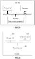
- FIG. 6 illustrates UE 600 according to an embodiment of the disclosure.
- the UE 600 includes a processing unit 601, a communication unit 602 and a storage unit 603.
- the processing unit 601 is configured to determine an uplink BWP which is active.
- the processing unit 601 is further configured to determine an SRS parameter configuration corresponding to the uplink BWP which is active.
- the processing unit 601 is further configured to transmit an SRS on the uplink BWP through the communication unit 602 according to the SRS parameter configuration.
- the processing unit 601 in terms of determining the active uplink BWP, is specifically configured to: determine the active uplink BWP according to BWP indication information; here, the latest received DCI for scheduling uplink transmission includes the BWP indication information.
- the processing unit 601 is further configured to receive high-layer signaling sent by a network device through the communication unit 602, the high-layer signaling being used to set an SRS parameter configuration respectively for each uplink BWP of the UE.
- the processing unit 601 is specifically configured to: determine the SRS parameter configuration corresponding to the active uplink BWP according to the high-layer signaling.
- the SRS parameter configuration includes a configuration of at least one SRS resource set in the uplink BWP and/or a configuration of at least one SRS resource in the uplink BWP.
- the configuration of the SRS resource set includes at least one of: a power control parameter configuration of the SRS resource set, a usage configuration of the SRS resource set, an aperiodic triggering state corresponding to the SRS resource set, or a CSI-RS resource configuration associated with the SRS resource set.
- the configuration of the SRS resource includes at least one of: a time-frequency resource configuration of the SRS resource, a sequence configuration of the SRS resource, an antenna port configuration of the SRS resource, a periodicity configuration of the SRS resource, a spatial relation configuration of the SRS resource, or an aperiodic triggering state corresponding to the SRS resource.
- the processing unit 601 is further configured to, under the condition that the DCI indicating activation of the uplink BWP includes aperiodic SRS triggering signaling, determine at least one SRS resource set corresponding to the uplink BWP as an SRS resource set which carries SRS transmission triggered by the aperiodic SRS triggering signaling.
- the processing unit 601 in terms of determining the at least one SRS resource set corresponding to the uplink BWP as the SRS resource set which carries SRS transmission triggered by the aperiodic SRS triggering signaling, is specifically configured to: determine an SRS resource set indicated by the aperiodic SRS triggering signaling as the SRS resource set which carries SRS transmission triggered by the aperiodic SRS triggering signaling.
- the SRS parameter configuration includes the power control parameter configuration of the SRS resource set; and in terms of transmitting the SRS on the uplink BWP according to the SRS parameter configuration, the processing unit 601 is specifically configured to:
- the SRS parameter configuration includes the usage configuration of the SRS resource set; and in terms of transmitting the SRS on the uplink BWP according to the SRS parameter configuration, the processing unit 601 is specifically configured to:
- the SRS parameter configuration includes the aperiodic triggering state corresponding to the SRS resource set; and in terms of transmitting the SRS on the uplink BWP according to the SRS parameter configuration, the processing unit 601 is specifically configured to:
- the SRS parameter configuration includes the CSI-RS resource configuration associated with the SRS resource set; and in terms of transmitting the SRS on the uplink BWP according to the SRS parameter configuration, the processing unit 601 is specifically configured to:
- the SRS parameter configuration includes the aperiodic triggering state corresponding to the SRS resource; and in terms of transmitting the SRS on the uplink BWP according to the SRS parameter configuration, the processing unit 601 is specifically configured to:
- the SRS parameter configuration includes the time-frequency resource configuration of the SRS resource, and in terms of transmitting the SRS on the uplink BWP according to the SRS parameter configuration, the processing unit 601 is specifically configured to:
- the SRS parameter configuration includes a spatial relation parameter of the SRS resource, and in terms of transmitting the SRS on the uplink BWP according to the SRS parameter configuration, the processing unit 601 is specifically configured to:
- the SRS parameter configuration includes the sequence configuration of the SRS resource, and in terms of transmitting the SRS on the uplink BWP according to the SRS parameter configuration, the processing unit 601 is specifically configured to:
- the SRS parameter configuration includes the periodicity configuration of the SRS resource, and in terms of transmitting the SRS on the uplink BWP according to the SRS parameter configuration, the processing unit 601 is specifically configured to:
- the processing unit 601 may be a processor or a controller (which may be, for example, a Central Processing Unit (CPU), a universal processor, a Digital Signal Processor (DSP), an Application-Specific Integrated Circuit (ASIC), a Field Programmable Gate Array (FPGA) or another programmable logical device, transistor logical device, hardware component or any combination thereof.
- the processing unit 601 may implement or execute various exemplary logical blocks, modules and circuits described in combination with the contents disclosed in the disclosure.
- the processor may also be a combination incapable of realizing a calculation function (for example, a combination including one or more microprocessors, or a combination of a DSP and a microprocessor).
- the communication unit 602 may be a transceiver, a transceiver circuit, a radio frequency chip, a communication interface and the like.
- the storage unit 603 may be a memory.
- the processing unit 601 is a processor
- the communication unit 602 is a communication interface
- the storage unit 603 is a memory
- the UE involved in the embodiment of the disclosure may be the UE shown in FIG. 5 .
- An embodiment of the disclosure also provides a computer-readable storage medium, which stores a computer program configured for electronic data exchange, the computer program enabling a computer to execute part of or all of the steps executed by the first network device in the abovementioned methods.
- An embodiment of the disclosure also provides a computer program product.
- the computer program product includes a non-transitory computer-readable storage medium storing a computer program.
- the computer program may be operated to enable a computer to execute part of or all of the steps executed by the first network device in the abovementioned methods.
- the computer program product may be a software installation package.
- a software instruction may consist of a corresponding software module, and the software module may be stored in a RAM, a flash memory, a Read Only Memory (ROM), an Erasable Programmable ROM (EPROM), an Electrically EPROM (EEPROM), a register, a hard disk, a mobile hard disk, a Compact Disc-ROM (CD-ROM) or a storage medium in any other form well known in the field.
- An exemplary storage medium is coupled to the processor, thereby enabling the processor to read information from the storage medium and write information into the storage medium.
- the storage medium may also be a component of the processor.
- the processor and the storage medium may be located in an ASIC.
- the ASIC may be located in an access network device, a target network device or a core network device.
- the processor and the storage medium may also exist as discrete components in an access network device, a target network device or a core network device.
- the embodiments may be implemented completely or partially in form of computer program product.
- the computer program product includes one or more computer instructions.
- the computer may be a universal computer, a dedicated computer, a computer network or another programmable device.
- the computer instruction may be stored in a computer-readable storage medium or transmitted from one computer-readable storage medium to another computer-readable storage medium.
- the computer instruction may be transmitted from a website, computer, server or data center to another website, computer, server or data center in a wired (for example, coaxial cable, optical fiber and Digital Subscriber Line (DSL)) or wireless (for example, infrared, wireless and microwave) manner.
- the computer-readable storage medium may be any available medium accessible by the computer or a data storage device, such as a server and a data center, including one or more integrated available media.
- the available medium may be a magnetic medium (for example, a floppy disk, a hard disk and a magnetic tape), an optical medium (for example, a Digital Video Disc (DVD)), a semiconductor medium (for example, a Solid State Disk (SSD)) or the like.
Applications Claiming Priority (1)
| Application Number | Priority Date | Filing Date | Title |
|---|---|---|---|
| PCT/CN2018/072502 WO2019136724A1 (fr) | 2018-01-12 | 2018-01-12 | Procédé de transmission de srs et dispositif associé |
Publications (2)
| Publication Number | Publication Date |
|---|---|
| EP3624531A1 true EP3624531A1 (fr) | 2020-03-18 |
| EP3624531A4 EP3624531A4 (fr) | 2020-07-29 |
Family
ID=67219260
Family Applications (1)
| Application Number | Title | Priority Date | Filing Date |
|---|---|---|---|
| EP18900436.9A Withdrawn EP3624531A4 (fr) | 2018-01-12 | 2018-01-12 | Procédé de transmission de srs et dispositif associé |
Country Status (14)
| Country | Link |
|---|---|
| US (2) | US10778475B2 (fr) |
| EP (1) | EP3624531A4 (fr) |
| JP (1) | JP2021515420A (fr) |
| KR (1) | KR20200108236A (fr) |
| CN (2) | CN110383919A (fr) |
| AU (1) | AU2018401514A1 (fr) |
| BR (1) | BR112019028096A2 (fr) |
| CA (1) | CA3066682C (fr) |
| IL (1) | IL271396A (fr) |
| PH (1) | PH12019502859A1 (fr) |
| RU (1) | RU2752008C1 (fr) |
| SG (1) | SG11201911747UA (fr) |
| WO (1) | WO2019136724A1 (fr) |
| ZA (1) | ZA201908252B (fr) |
Families Citing this family (20)
| Publication number | Priority date | Publication date | Assignee | Title |
|---|---|---|---|---|
| TWI654893B (zh) * | 2016-10-07 | 2019-03-21 | 華碩電腦股份有限公司 | 無線通訊系統中導出上行參考訊號的傳送功率的方法和設備 |
| BR112019028096A2 (pt) | 2018-01-12 | 2020-07-28 | Guangdong Oppo Mobile Telecommunications Corp., Ltd. | método para transmissão de sinal de referência de som, e equipamento de usuário |
| CA3088813C (fr) * | 2018-01-19 | 2022-12-06 | Guangdong Oppo Mobile Telecommunications Corp., Ltd. | Procede de transmission de signal de reference de sondage, dispositif de reseau et dispositif terminal |
| US11088791B2 (en) * | 2018-05-21 | 2021-08-10 | Qualcomm Incorporated | Choosing an SRS resource set when multiple sets are configured |
| US10791533B2 (en) * | 2018-07-19 | 2020-09-29 | Huawei Technologies Co., Ltd. | Methods and systems for generalized RACH-less mobility |
| US11849459B2 (en) * | 2019-07-08 | 2023-12-19 | Qualcomm Incorporated | Bandwidth part configuration for sidelink communication |
| CN112583544B (zh) * | 2019-09-27 | 2023-04-07 | 维沃移动通信有限公司 | 确定源参考信号信息的方法和通信设备 |
| US11452089B2 (en) * | 2019-12-23 | 2022-09-20 | Qualcomm Incorporated | Signaling to activate uplink trigger states |
| CN111130742B (zh) * | 2019-12-27 | 2021-12-03 | 北京紫光展锐通信技术有限公司 | 上行srs传输方法、装置及存储介质 |
| CN115552945A (zh) * | 2020-05-15 | 2022-12-30 | 苹果公司 | 用于针对波束搜索延迟降低的控制信令的系统和方法 |
| CN115516799A (zh) * | 2020-05-18 | 2022-12-23 | Oppo广东移动通信有限公司 | 一种srs的配置方法及装置、网络设备、终端设备 |
| CN113922933B (zh) * | 2020-07-10 | 2023-01-06 | 维沃移动通信有限公司 | 一种载波切换处理方法、装置及终端 |
| US20220045884A1 (en) * | 2020-08-06 | 2022-02-10 | Samsung Electronics Co., Ltd. | Methods and apparatuses for uplink channel sounding between bwps |
| WO2022047615A1 (fr) * | 2020-09-01 | 2022-03-10 | Qualcomm Incorporated | Activation basée sur un élément de commande (ce) de commande d'accès au support (mac) pour des requêtes de signal de référence initiées par un équipement utilisateur (ue) |
| CN114339890A (zh) * | 2020-09-29 | 2022-04-12 | 维沃移动通信有限公司 | 通信资源激活方法、终端及网络侧设备 |
| CN112419699A (zh) * | 2020-11-04 | 2021-02-26 | 国网山西省电力公司营销服务中心 | 适用于电力系统的资源配置方法及系统 |
| CN112702791B (zh) * | 2020-12-11 | 2022-06-28 | 杭州红岭通信息科技有限公司 | 一种多bwp下探测参考信号的资源分配方法 |
| KR20230160814A (ko) * | 2021-03-26 | 2023-11-24 | 인텔 코포레이션 | 스케줄링 정보를 갖지 않는 다운링크 제어 정보(dci) 포맷들을 통해 트리거되는 사운딩 참조 신호(srs) 송신 |
| US20240048348A1 (en) * | 2021-04-25 | 2024-02-08 | Qualcomm Incorporated | Adaptive antenna switching and resource configuration within a bandwidth part |
| CN115441998A (zh) * | 2021-06-03 | 2022-12-06 | 北京三星通信技术研究有限公司 | 无线通信系统中的终端、基站及由其执行的方法 |
Family Cites Families (33)
| Publication number | Priority date | Publication date | Assignee | Title |
|---|---|---|---|---|
| PL2241049T3 (pl) * | 2008-01-08 | 2019-09-30 | Hmd Global Oy | Układ sondującego sygnału odniesienia |
| US8817818B2 (en) * | 2008-04-23 | 2014-08-26 | Texas Instruments Incorporated | Backward compatible bandwidth extension |
| CN101651469B (zh) * | 2008-08-15 | 2013-07-24 | 三星电子株式会社 | 用于lte系统中发送上行监测参考符号的跳频方法 |
| EP2166694A3 (fr) * | 2008-09-18 | 2012-01-04 | Samsung Electronics Co., Ltd. | Transmission de signaux de référence dans des systèmes de communication TDD |
| US8737335B2 (en) * | 2009-06-19 | 2014-05-27 | Kddi Corporation | Reference signal transmission scheduling device and reference signal transmission scheduling method |
| US9276710B2 (en) * | 2009-12-21 | 2016-03-01 | Qualcomm Incorporated | Method and apparatus for resource allocation with carrier extension |
| US8848520B2 (en) | 2010-02-10 | 2014-09-30 | Qualcomm Incorporated | Aperiodic sounding reference signal transmission method and apparatus |
| KR101791266B1 (ko) * | 2010-02-12 | 2017-10-30 | 엘지전자 주식회사 | 무선 통신 시스템에서 데이터 전송 방법 및 장치 |
| CN102104973B (zh) * | 2010-05-31 | 2013-09-25 | 电信科学技术研究院 | 非周期srs的传输方法和设备 |
| CN102412889A (zh) * | 2010-10-09 | 2012-04-11 | 普天信息技术研究院有限公司 | 一种增强上行侦听参考信号的方法 |
| CN103314631A (zh) * | 2011-01-07 | 2013-09-18 | 富士通株式会社 | 探测参考信号的发送方法、基站和用户设备 |
| WO2012092721A1 (fr) * | 2011-01-07 | 2012-07-12 | 富士通株式会社 | Procédé et équipement utilisateur pour transmettre un signal de référence de sondage, et nœud b évolué correspondant |
| EP3331183B1 (fr) * | 2011-02-15 | 2019-06-12 | LG Electronics Inc. | Procédé et appareil pour transmettre des informations de contrôle de qualité de canal dans un système d'accès sans fil |
| US9559820B2 (en) * | 2011-02-18 | 2017-01-31 | Qualcomm Incorporated | Feedback reporting based on channel state information reference signal (CSI-RS) groups |
| GB2486926B (en) * | 2011-06-02 | 2013-10-23 | Renesas Mobile Corp | Frequency hopping in license-exempt/shared bands |
| US8675605B2 (en) * | 2011-06-02 | 2014-03-18 | Broadcom Corporation | Frequency hopping in license-exempt/shared bands |
| CN102868500A (zh) * | 2011-07-07 | 2013-01-09 | 华为技术有限公司 | 信道信息的反馈方法、终端和基站 |
| CN103369654A (zh) * | 2012-04-09 | 2013-10-23 | 电信科学技术研究院 | 功控参数的指示及功控方法和设备 |
| US9054846B2 (en) * | 2012-07-31 | 2015-06-09 | Telefonaktiebolaget L M Ericsson (Publ) | Power control for simultaneous transmission of ACK/NACK and channel-state information in carrier aggregation systems |
| US9450722B2 (en) * | 2012-08-09 | 2016-09-20 | Telefonaktiebolaget Lm Ericsson (Publ) | Reference signal mapping |
| US9215725B2 (en) * | 2012-08-22 | 2015-12-15 | Qualcomm Incorporated | Adjusting channel state information reports to improve multi-radio coexistence |
| US9844072B2 (en) * | 2014-09-26 | 2017-12-12 | Qualcomm Incorporated | Ultra-low latency LTE uplink frame structure |
| US9785781B2 (en) * | 2014-12-08 | 2017-10-10 | Dotalign, Inc. | Method, apparatus, and computer-readable medium for data exchange |
| WO2017015813A1 (fr) * | 2015-07-27 | 2017-02-02 | 华为技术有限公司 | Procédé de communication et dispositif à réseau |
| WO2017218794A1 (fr) * | 2016-06-15 | 2017-12-21 | Convida Wireless, Llc | Signalisation de commande de téléchargement amont pour une nouvelle radio |
| WO2018121621A1 (fr) * | 2016-12-27 | 2018-07-05 | Chou, Chie-Ming | Procédé de signalisation d'indicateurs de partie de bande passante (bwp) et équipement de communication radio l'utilisant |
| US10575217B2 (en) * | 2017-08-11 | 2020-02-25 | Qualcomm Incorporated | Techniques and apparatuses for managing sounding reference signal (SRS) transmissions in a bandwidth part |
| US10721765B2 (en) * | 2017-09-29 | 2020-07-21 | Kt Corporation | Method and apparatus for switching bandwidth part in new radio |
| WO2019066625A1 (fr) * | 2017-09-29 | 2019-04-04 | Samsung Electronics Co., Ltd. | Procédé et appareil permettant de transmettre un signal de référence dans un système de communication sans fil |
| CN109600826A (zh) * | 2017-09-30 | 2019-04-09 | 华为技术有限公司 | 功率控制方法及装置 |
| US10869312B2 (en) * | 2017-10-31 | 2020-12-15 | Ofinno, Llc | Scheduling with bandwidth part switching |
| US10873481B2 (en) * | 2017-11-27 | 2020-12-22 | Qualcomm Incorporated | Reference signal transmission window and timing considerations |
| BR112019028096A2 (pt) | 2018-01-12 | 2020-07-28 | Guangdong Oppo Mobile Telecommunications Corp., Ltd. | método para transmissão de sinal de referência de som, e equipamento de usuário |
-
2018
- 2018-01-12 BR BR112019028096-0A patent/BR112019028096A2/pt not_active IP Right Cessation
- 2018-01-12 CN CN201880015787.5A patent/CN110383919A/zh active Pending
- 2018-01-12 EP EP18900436.9A patent/EP3624531A4/fr not_active Withdrawn
- 2018-01-12 WO PCT/CN2018/072502 patent/WO2019136724A1/fr unknown
- 2018-01-12 RU RU2020100195A patent/RU2752008C1/ru active
- 2018-01-12 AU AU2018401514A patent/AU2018401514A1/en not_active Abandoned
- 2018-01-12 CA CA3066682A patent/CA3066682C/fr active Active
- 2018-01-12 JP JP2019566137A patent/JP2021515420A/ja active Pending
- 2018-01-12 CN CN201911301705.6A patent/CN111106919B/zh active Active
- 2018-01-12 KR KR1020197035315A patent/KR20200108236A/ko active Search and Examination
- 2018-01-12 SG SG11201911747UA patent/SG11201911747UA/en unknown
-
2019
- 2019-12-02 US US16/700,966 patent/US10778475B2/en active Active
- 2019-12-11 ZA ZA2019/08252A patent/ZA201908252B/en unknown
- 2019-12-12 IL IL271396A patent/IL271396A/en unknown
- 2019-12-18 PH PH12019502859A patent/PH12019502859A1/en unknown
-
2020
- 2020-08-11 US US16/990,902 patent/US20200374156A1/en not_active Abandoned
Also Published As
| Publication number | Publication date |
|---|---|
| JP2021515420A (ja) | 2021-06-17 |
| WO2019136724A1 (fr) | 2019-07-18 |
| ZA201908252B (en) | 2020-10-28 |
| BR112019028096A2 (pt) | 2020-07-28 |
| CN110383919A (zh) | 2019-10-25 |
| KR20200108236A (ko) | 2020-09-17 |
| CA3066682C (fr) | 2022-03-01 |
| IL271396A (en) | 2020-01-30 |
| AU2018401514A1 (en) | 2020-01-16 |
| CA3066682A1 (fr) | 2019-07-18 |
| US10778475B2 (en) | 2020-09-15 |
| US20200106647A1 (en) | 2020-04-02 |
| US20200374156A1 (en) | 2020-11-26 |
| RU2752008C1 (ru) | 2021-07-21 |
| EP3624531A4 (fr) | 2020-07-29 |
| CN111106919A (zh) | 2020-05-05 |
| CN111106919B (zh) | 2021-03-02 |
| PH12019502859A1 (en) | 2020-10-05 |
| SG11201911747UA (en) | 2020-01-30 |
Similar Documents
| Publication | Publication Date | Title |
|---|---|---|
| US10778475B2 (en) | Method and device for SRS transmission | |
| CA3064481C (fr) | Procede de transmission de donnees de liaison montante, et dispositifs associes | |
| US20230300809A1 (en) | Terminal device, base station device, and method | |
| US20210351960A1 (en) | Uplink transmission instruction method, terminal, base station and computer storage medium | |
| US20210288852A1 (en) | Guard band indication method and apparatus | |
| EP3846532A1 (fr) | Procédé et dispositif commande de puissance | |
| BR112016010481B1 (pt) | Sistema de comunicações, equipamento de usuário, estação base de onda milimétrica e método de comunicações | |
| US20220263641A1 (en) | Method For Configuring CLI Measurement And Communications Apparatus | |
| US11510155B2 (en) | Communication method, communications apparatus, and computer-readable storage medium | |
| US10917895B2 (en) | Power control method and apparatus | |
| KR20200111788A (ko) | 데이터 전송 방법, 핸드오버 방법 및 관련 기기 | |
| WO2022253150A1 (fr) | Procédé et appareil de transmission de données | |
| US20230300760A1 (en) | Terminal and communication method | |
| CN111052656A (zh) | 测量资源指示方法及相关设备 | |
| US20230403116A1 (en) | Method, device and computer readable medium for communication | |
| WO2023279332A1 (fr) | Procédé, dispositif et support lisible par ordinateur pour la communication | |
| CN111406393B (zh) | 参数调整方法及相关设备 | |
| CN116548040A (zh) | 一种针对第二网络设备的波束管理方法、装置、设备及存储介质 |
Legal Events
| Date | Code | Title | Description |
|---|---|---|---|
| STAA | Information on the status of an ep patent application or granted ep patent |
Free format text: STATUS: THE INTERNATIONAL PUBLICATION HAS BEEN MADE |
|
| PUAI | Public reference made under article 153(3) epc to a published international application that has entered the european phase |
Free format text: ORIGINAL CODE: 0009012 |
|
| STAA | Information on the status of an ep patent application or granted ep patent |
Free format text: STATUS: REQUEST FOR EXAMINATION WAS MADE |
|
| 17P | Request for examination filed |
Effective date: 20191213 |
|
| AK | Designated contracting states |
Kind code of ref document: A1 Designated state(s): AL AT BE BG CH CY CZ DE DK EE ES FI FR GB GR HR HU IE IS IT LI LT LU LV MC MK MT NL NO PL PT RO RS SE SI SK SM TR |
|
| AX | Request for extension of the european patent |
Extension state: BA ME |
|
| RIC1 | Information provided on ipc code assigned before grant |
Ipc: H04L 5/00 20060101AFI20200316BHEP Ipc: H04W 72/04 20090101ALI20200316BHEP |
|
| REG | Reference to a national code |
Ref country code: DE Ref legal event code: R079 Free format text: PREVIOUS MAIN CLASS: H04W0072040000 Ipc: H04L0005000000 |
|
| A4 | Supplementary search report drawn up and despatched |
Effective date: 20200626 |
|
| RIC1 | Information provided on ipc code assigned before grant |
Ipc: H04W 72/04 20090101ALI20200622BHEP Ipc: H04L 5/00 20060101AFI20200622BHEP |
|
| STAA | Information on the status of an ep patent application or granted ep patent |
Free format text: STATUS: EXAMINATION IS IN PROGRESS |
|
| 17Q | First examination report despatched |
Effective date: 20210224 |
|
| DAV | Request for validation of the european patent (deleted) | ||
| DAX | Request for extension of the european patent (deleted) | ||
| STAA | Information on the status of an ep patent application or granted ep patent |
Free format text: STATUS: THE APPLICATION IS DEEMED TO BE WITHDRAWN |
|
| 18D | Application deemed to be withdrawn |
Effective date: 20221020 |