EP3624275B1 - Connection terminal - Google Patents
Connection terminal Download PDFInfo
- Publication number
- EP3624275B1 EP3624275B1 EP19196214.1A EP19196214A EP3624275B1 EP 3624275 B1 EP3624275 B1 EP 3624275B1 EP 19196214 A EP19196214 A EP 19196214A EP 3624275 B1 EP3624275 B1 EP 3624275B1
- Authority
- EP
- European Patent Office
- Prior art keywords
- connection body
- male connection
- wall surface
- side protruding
- inlet
- Prior art date
- Legal status (The legal status is an assumption and is not a legal conclusion. Google has not performed a legal analysis and makes no representation as to the accuracy of the status listed.)
- Active
Links
- 238000003780 insertion Methods 0.000 claims description 76
- 230000037431 insertion Effects 0.000 claims description 76
- 238000003825 pressing Methods 0.000 claims description 7
- 238000000034 method Methods 0.000 description 13
- 230000008878 coupling Effects 0.000 description 3
- 238000010168 coupling process Methods 0.000 description 3
- 238000005859 coupling reaction Methods 0.000 description 3
- 239000007769 metal material Substances 0.000 description 2
- 230000001419 dependent effect Effects 0.000 description 1
- 230000000694 effects Effects 0.000 description 1
- 238000009413 insulation Methods 0.000 description 1
- 239000002184 metal Substances 0.000 description 1
- 238000005476 soldering Methods 0.000 description 1
- 238000003466 welding Methods 0.000 description 1
Images


Classifications
-
- H—ELECTRICITY
- H01—ELECTRIC ELEMENTS
- H01R—ELECTRICALLY-CONDUCTIVE CONNECTIONS; STRUCTURAL ASSOCIATIONS OF A PLURALITY OF MUTUALLY-INSULATED ELECTRICAL CONNECTING ELEMENTS; COUPLING DEVICES; CURRENT COLLECTORS
- H01R13/00—Details of coupling devices of the kinds covered by groups H01R12/70 or H01R24/00 - H01R33/00
- H01R13/02—Contact members
- H01R13/15—Pins, blades or sockets having separate spring member for producing or increasing contact pressure
- H01R13/187—Pins, blades or sockets having separate spring member for producing or increasing contact pressure with spring member in the socket
-
- H—ELECTRICITY
- H01—ELECTRIC ELEMENTS
- H01R—ELECTRICALLY-CONDUCTIVE CONNECTIONS; STRUCTURAL ASSOCIATIONS OF A PLURALITY OF MUTUALLY-INSULATED ELECTRICAL CONNECTING ELEMENTS; COUPLING DEVICES; CURRENT COLLECTORS
- H01R13/00—Details of coupling devices of the kinds covered by groups H01R12/70 or H01R24/00 - H01R33/00
- H01R13/40—Securing contact members in or to a base or case; Insulating of contact members
- H01R13/42—Securing in a demountable manner
-
- H—ELECTRICITY
- H01—ELECTRIC ELEMENTS
- H01R—ELECTRICALLY-CONDUCTIVE CONNECTIONS; STRUCTURAL ASSOCIATIONS OF A PLURALITY OF MUTUALLY-INSULATED ELECTRICAL CONNECTING ELEMENTS; COUPLING DEVICES; CURRENT COLLECTORS
- H01R13/00—Details of coupling devices of the kinds covered by groups H01R12/70 or H01R24/00 - H01R33/00
- H01R13/02—Contact members
- H01R13/193—Means for increasing contact pressure at the end of engagement of coupling part, e.g. zero insertion force or no friction
-
- H—ELECTRICITY
- H01—ELECTRIC ELEMENTS
- H01R—ELECTRICALLY-CONDUCTIVE CONNECTIONS; STRUCTURAL ASSOCIATIONS OF A PLURALITY OF MUTUALLY-INSULATED ELECTRICAL CONNECTING ELEMENTS; COUPLING DEVICES; CURRENT COLLECTORS
- H01R13/00—Details of coupling devices of the kinds covered by groups H01R12/70 or H01R24/00 - H01R33/00
- H01R13/62—Means for facilitating engagement or disengagement of coupling parts or for holding them in engagement
-
- H—ELECTRICITY
- H01—ELECTRIC ELEMENTS
- H01R—ELECTRICALLY-CONDUCTIVE CONNECTIONS; STRUCTURAL ASSOCIATIONS OF A PLURALITY OF MUTUALLY-INSULATED ELECTRICAL CONNECTING ELEMENTS; COUPLING DEVICES; CURRENT COLLECTORS
- H01R13/00—Details of coupling devices of the kinds covered by groups H01R12/70 or H01R24/00 - H01R33/00
- H01R13/02—Contact members
- H01R13/04—Pins or blades for co-operation with sockets
- H01R13/05—Resilient pins or blades
- H01R13/052—Resilient pins or blades co-operating with sockets having a circular transverse section
-
- H—ELECTRICITY
- H01—ELECTRIC ELEMENTS
- H01R—ELECTRICALLY-CONDUCTIVE CONNECTIONS; STRUCTURAL ASSOCIATIONS OF A PLURALITY OF MUTUALLY-INSULATED ELECTRICAL CONNECTING ELEMENTS; COUPLING DEVICES; CURRENT COLLECTORS
- H01R13/00—Details of coupling devices of the kinds covered by groups H01R12/70 or H01R24/00 - H01R33/00
- H01R13/02—Contact members
- H01R13/10—Sockets for co-operation with pins or blades
- H01R13/11—Resilient sockets
- H01R13/111—Resilient sockets co-operating with pins having a circular transverse section
Landscapes
- Details Of Connecting Devices For Male And Female Coupling (AREA)
- Connector Housings Or Holding Contact Members (AREA)
Description
- The present invention relates to a connection terminal.
-
US 2012/083 167 A1 discloses a connection terminal as described in the preamble ofclaim 1.EP 2 590 268 A1 andUS 2016/079686 A1 disclose also a connection terminal as described in the preamble ofclaim 1.JP 2013 089 309 A JP 2002 015 803 A US 7 789 722 B2 also refer to a connection terminal. A connection terminal including a female connection body, a male connection body inserted into a housing space of the female connection body and electrically connected to the female connection body, and an elastic member configured to bias, in the housing space, the male connection body toward a protruding portion formed on an inner wall surface of the female connection body has been known. In such a connection terminal, holding force for holding the male connection body in the housing space is ensured by the protruding portion and the elastic member. - For example,
Japanese Patent Application Laid-open No. 2016-119292 - According to the connector of
Japanese Patent Application Laid-open No. 2016-119292 - For the connection terminal, it has been demanded that holding force for holding the male connection body be ensured while insertion force upon insertion of the male connection body into the housing space of the female connection body be suppressed low.
- An object of the present invention is to provide a connection terminal configured so that holding force for holding a male connection body can be ensured while insertion force upon insertion of the male connection body into a housing space of a female connection body can be suppressed low.
- The above and other objects of the invention are achieved by the connection terminal according to
claim 1. Preferred embodiments are claimed in the dependent claims. A connection terminal according toclaim 1 includes a tubular female connection body having conductivity and having a housing space extending along an axial direction; a male connection body having conductivity and configured to be inserted into the housing space to a fitting completion position along the axial direction; and an elastic member supported by an inner wall surface of the female connection body surrounding the housing space, having a contact point portion configured to contact an outer wall surface of the male connection body, and to press the male connection body, wherein the female connection body has a far-side protruding portion protruding from a position of the inner wall surface on a far side in an insertion direction with respect to the contact point portion, and an inlet-side protruding portion protruding from a position of the inner wall surface on an inlet side in the insertion direction with respect to the contact point portion, the far-side protruding portion and the inlet-side protruding portion configured to support the outer wall surface of the male connection body at the fitting completion position against pressing force of the elastic member, the outer wall surface of the male connection body has a first recessed portion formed at a portion facing the inlet-side protruding portion such that when the male connection body is inserted into the housing space, the inlet-side protruding portion passes by the first recessed portion, the first recessed portion is, at the outer wall surface of the male connection body, formed along the insertion direction at an intermediate portion between a front end portion and a back end portion of the male connection body with respect to a position facing the inlet-side protruding portion and a back side in the insertion direction with respect to a position facing the far-side protruding portion at the fitting completion position, so that the first recessed portion is arranged between the inlet-side protruding portion and the far-side protruding portion at the fitting completion position. - The above and other objects, features, advantages and technical and industrial significance of this invention will be better understood by reading the following detailed description of presently preferred embodiments of the invention, when considered in connection with the accompanying drawings.
-
-
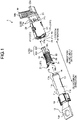
FIG. 1 is an exploded perspective view illustrating a connection terminal according to an embodiment; -
FIG. 2 is a perspective view illustrating the connection terminal according to the embodiment; -
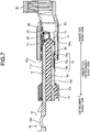
FIG. 3 is a perspective view illustrating a female terminal of the embodiment; -
FIG. 4 is a plan view illustrating the female terminal of the embodiment; -
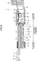
FIG. 5 is a plan view illustrating a male terminal of the embodiment; -
FIG. 6 is a sectional view illustrating the process of inserting a male connection body into a housing space in the embodiment; -
FIG. 7 is a sectional view illustrating the process of inserting the male connection body into the housing space in the embodiment; -
FIG. 8 is a sectional view illustrating the process of inserting the male connection body into the housing space in the embodiment; -
FIG. 9 is a perspective view illustrating another example of the male terminal of the embodiment; -
FIG. 10 is a perspective view illustrating a male terminal of a variation of the embodiment; -
FIG. 11 is a sectional view illustrating the process of inserting a male connection body into a housing space in the variation of the embodiment; -
FIG. 12 is a sectional view illustrating the process of inserting the male connection body into the housing space in the variation of the embodiment; and -
FIG. 13 is a sectional view illustrating the process of inserting the male connection body into the housing space in the variation of the embodiment. - Hereinafter, a connection terminal according to an embodiment of the present invention will be described in detail with reference to the drawings. Note that this invention is not limited by this embodiment.
- The embodiment will be described with reference to
FIGS. 1 to 8 . The embodiment relates to a connection terminal.FIG. 1 is an exploded perspective view illustrating the connection terminal according to the embodiment.FIG. 2 is a perspective view illustrating the connection terminal according to the embodiment.FIG. 3 is a perspective view illustrating a female terminal of the embodiment.FIG. 4 is a plan view illustrating the female terminal of the embodiment.FIG. 5 is a plan view illustrating a male terminal of the embodiment.FIG. 6 is a sectional view illustrating the process of inserting a male connection body into a housing space in the embodiment.FIG. 7 is a sectional view illustrating the process of inserting the male connection body into the housing space in the embodiment.FIG. 8 is a sectional view illustrating the process of inserting the male connection body into the housing space in the embodiment.FIG. 9 is a perspective view illustrating another example of the male terminal of the embodiment. Note thatFIGS. 6 to 8 illustrate a section corresponding to a VI-VI section illustrated inFIG. 4 . - As illustrated in
FIG. 1 , aconnection terminal 1 of the present embodiment includes amale terminal 10, afemale terminal 20, and anelastic member 30. - The
male terminal 10 is made of a conductive metal material. Themale terminal 10 has amale connection body 11, aterminal connection body 12, and afixing portion 15. - In the
male terminal 10, themale connection body 11 is a portion inserted into a later-described housing space HS of thefemale terminal 20 and electrically connected to thefemale terminal 20. Themale connection body 11 is, for example, formed in a columnar shape. In the embodiment, themale connection body 11 is formed in a circular columnar shape. In the embodiment, an axial direction of themale connection body 11 is an insertion and removal direction for thefemale terminal 20. Note that in the specification, a direction which is along the insertion and removal direction and in which themale connection body 11 is inserted into the housing space HS of thefemale terminal 20 will be referred to as an "insertion direction," and a direction in which themale connection body 11 is removed from thefemale terminal 20 will be referred to as a "removal direction." - The
terminal connection body 12 is formed in a flat plate shape. Theterminal connection body 12 has, for example, aninsertion hole 12a into which a terminal screw is to be inserted. Theinsertion hole 12a is formed in the vicinity of the center of the flat plate-shapedterminal connection body 12. - In the embodiment, the
male connection body 11 is formed in such a manner that the periphery of aninsulating portion 10a extending in the axial direction is covered with a conductivetubular member 10b (seeFIG. 6 ). Themale connection body 11 has atip end portion 14 on a front end side (a front side in the insertion direction). Thetip end portion 14 of the embodiment is formed by a portion of the insulatingportion 10a exposed through a front end side end portion of thetubular member 10b. Thetip end portion 14 is formed in a tapered shape, and is formed such that the diameter thereof increases from the front end side to a back end side (a back side in the insertion direction). At anouter wall surface 11d of themale connection body 11, thetubular member 10b forms an outer wall surface electrically connected to afemale connection body 21. At theouter wall surface 11d of themale connection body 11, a back end side outer wall surface of thetip end portion 14 is formed flush with the outer wall surface of thetubular member 10b. Theterminal connection body 12 protrudes in the axial direction from one end portion of the tubular member. - The fixing
portion 15 is arranged between themale connection body 11 and theterminal connection body 12. The fixingportion 15 has insulation properties, and is provided to cover thetubular member 10b in the vicinity of a base end portion of theterminal connection body 12. Ahole 10c is formed at a portion of thetubular member 10b covered with the fixingportion 15, and the fixingportion 15 is integrated with the insulatingportion 10a of themale connection body 11 through thehole 10c (seeFIG. 6 ). With this configuration, the fixingportion 15 restricts shift of the position of thetubular member 10b relative to the insulatingportion 10a. - As illustrated in
FIG. 1 , thefemale terminal 20 has thefemale connection body 21, an electricwire connection body 22, and acoupling body 23. Thefemale connection body 21 is formed in a tubular body. In the embodiment, thefemale connection body 21 is formed in a cylindrical shape. Thefemale connection body 21 has the housing space HS surrounded by aninner wall surface 21c of thefemale connection body 21. The housing space HS extends along an axial direction of thefemale connection body 21. The housing space HS is formed in a shape (e.g., a tubular shape) corresponding to the outer shape of themale connection body 11. In the embodiment, the housing space HS is formed in a circular columnar shape. Both ends of thefemale connection body 21 in the axial direction open, and communicate the housing space HS and an external space with each other. As illustrated inFIGS. 1 and2 , one end opening (hereinafter referred to as a "first opening 21a") is utilized as an inlet for insertion of themale connection body 11. Moreover, in the embodiment, themale connection body 11 inserted through thefirst opening 21a protrudes from the other end opening (hereinafter referred to as a "second opening 21b") as illustrated inFIG. 2 . - The electric
wire connection body 22 is a portion electrically connected to a conductive portion of an electric wire (not illustrated). The electricwire connection body 22 is electrically connected to the conductive portion of the electric wire by pressure bonding such as swaging. In the embodiment, the electricwire connection body 22 has a pair ofbarrel piece portions barrel piece portions wire connection body 22 and the conductive portion of the electric wire are electrically connected to each other. Note that the electricwire connection body 22 may be a portion electrically connected to the conductive portion of the electric wire by, e.g., welding or soldering. Thecoupling body 23 is arranged between thefemale connection body 21 and the electricwire connection body 22. Thecoupling body 23 connects thefemale connection body 21 and the electricwire connection body 22 to each other. Thefemale terminal 20 is made of a conductive metal material. - As illustrated in
FIG. 3 , thefemale terminal 20 has far-side protruding portions 24 and inlet-side protruding portions 25. The far-side protruding portions 24 and the inlet-side protruding portions 25 protrude from theinner wall surface 21c of thefemale connection body 21 in the housing space HS. The far-side protruding portion 24 and the inlet-side protruding portion 25 are members configured to hold, together with the later-describedelastic member 30, themale connection body 11 inserted into the housing space HS to a fitting completion position. As illustrated inFIG. 4 , the far-side protruding portions 24 and the inlet-side protruding portions 25 of the embodiment are arranged in one region R1 when thefemale connection body 21 is divided into two regions R1, R2 along the insertion and removal direction. The regions R1, R2 described herein are separated substantially symmetrically with respect to the center axis of thefemale connection body 21. That is, the regions R1, R2 are regions formed in such a manner that the female connection body is divided in half along the insertion and removal direction. - Two far-
side protruding portions 24 are arranged with a spacing in a circumferential direction of theinner wall surface 21c in the vicinity of a second-opening-21b-side end portion of thefemale connection body 21. Moreover, two inlet-side protruding portions 25 are arranged with a spacing in the circumferential direction of theinner wall surface 21c in the vicinity of a first-opening-21a-side (inlet-side) end portion of thefemale connection body 21. The far-side protruding portions 24 and the inlet-side protruding portions 25 are arranged such that the single far-side protruding portion 24 and the single inlet-side protruding portion 25 are arranged in each of two regions R11, R12 formed by further division of the above-described divided region R1 into two regions along the insertion and removal direction. The regions R11, R12 are regions formed in such a manner that the region R1 is divided in half along the insertion and removal direction. When thefemale connection body 21 is viewed from afirst opening 21a side, the far-side protruding portion 24 and the inlet-side protruding portion 25 are arranged overlapping with each other in the insertion and removal direction. - As illustrated in
FIG. 1 , theelastic member 30 of the embodiment is inserted into the housing space HS through thefirst opening 21a. Theelastic member 30 has conductivity and elasticity. Theelastic member 30 is arranged in the other region R2 when thefemale connection body 21 is divided into two regions R1, R2 along the insertion and removal direction (seeFIG. 4 ). Theelastic member 30 has male-side contact bodies 33 and two female-side contact bodies 34. The female-side contact body 34 is formed in an arc shape along theinner wall surface 21c of thefemale connection body 21. As illustrated inFIG. 1 , two female-side contact bodies 34 are arranged facing each other in the insertion and removal direction. The male-side contact body 33 is a plate spring-shaped member extending in the insertion and removal direction. The male-side contact bodies 33 are arranged between two female-side contact bodies 34, and end portions of the male-side contact body 33 are each connected to the female-side contact bodies 34. In the embodiment, multiple male-side contact bodies 33 are provided between two female-side contact bodies 34 as illustrated inFIG. 3 . When theelastic member 30 is arranged in the housing space HS, the multiple male-side contact bodies 33 are arranged in the circumferential direction of theinner wall surface 21c. Theelastic member 30 is made of conductive metal with the elasticity. - In the housing space HS, the
elastic member 30 is supported by theinner wall surface 21c. The male-side contact body 33 has a firstcontact point portion 30a contacting theouter wall surface 11d of themale connection body 11. Moreover, the female-side contact body 34 has multiple secondcontact point portions 30b contacting theinner wall surface 21c (seeFIG. 1 ). The secondcontact point portion 30b is provided in a protrusion shape on a surface of the female-side contact body 34 facing theinner wall surface 21c. The male-side contact body 33 is curved such that the firstcontact point portion 30a protrudes to the center axis of the housing space HS. - The
female connection body 21 and theelastic member 30 have a first stop structure LS1 and a second stop structure LS2. The first stop structure LS1 restricts position shift of theelastic member 30 relative to thefemale connection body 21 in the insertion direction. The second stop structure LS2 restricts position shift of theelastic member 30 relative to thefemale connection body 21 in the removal direction. - The first stop structure LS1 includes first
stop target portions 31 provided at theelastic member 30, andfirst stop portions 21d provided at thefemale connection body 21. As illustrated inFIG. 2 , the firststop target portion 31 is formed to protrude from theelastic member 30 to aninner wall surface 21c side of thefemale connection body 21 in a state in which theelastic member 30 is housed in the housing space HS. Thefirst stop portion 21d is a portion formed in a cutout shape at a first-opening-21aside end portion of thefemale connection body 21. When theelastic member 30 is housed in the housing space HS, the firststop target portion 31 is inserted into thefirst stop portion 21d. As illustrated inFIG. 3 , thefirst stop portion 21d has awall surface 21e perpendicular to the insertion direction of themale connection body 11, and awall surface 21f perpendicular to a circumferential direction of thefemale connection body 21. Thefirst stop portion 21d restricts, by thewall surface 21e, position shift of theelastic member 30 relative to thefemale connection body 21 in the insertion direction, and by thewall surface 21f, restricts position shift of theelastic member 30 relative to thefemale connection body 21 in the circumferential direction. - As illustrated in
FIG. 1 , the second stop structure LS2 includes a secondstop target portion 32 provided at theelastic member 30, andsecond stop portions 21g provided at thefemale connection body 21. The secondstop target portion 32 is formed at an end portion of theelastic member 30 arranged on asecond opening 21b side. The secondstop target portion 32 has ashaft portion 32a extending along the insertion direction and a pair ofpiece portions 32b, 32c. The pair ofpiece portions 32b, 32c are provided in an arc shape along the circumferential direction of thefemale connection body 21 at an end portion of theshaft portion 32a in an extension direction thereof. Thesecond stop portions 21g are portions each protruding from the second-opening-21b-side end portion of thefemale connection body 21 to face thepiece portions 32b, 32c. Thesecond stop portions 21g each contact thepiece portions 32b, 32c to restrict position shift of theelastic member 30 relative to thefemale connection body 21 in the removal direction. - As illustrated in
FIG. 5 , theouter wall surface 11d of themale connection body 11 has first recessedportions 13. The first recessedportion 13 is a portion for reducing mechanical interference of the inlet-side protruding portion 25 with themale connection body 11 when themale connection body 11 is inserted into thefemale connection body 21. The first recessedportion 13 is formed at a portion facing the inlet-side protruding portion 25 when themale connection body 11 is inserted into thefemale connection body 21. When themale connection body 11 is inserted into the housing space HS, the inlet-side protruding portion 25 passes by the first recessedportion 13. - The first recessed
portion 13 of the embodiment is arranged at anintermediate portion 11c between afront end portion 11a and aback end portion 11b of themale connection body 11. Thefront end portion 11a is a portion of themale connection body 11, which is inserted to the fitting completion position, contacting the far-side protruding portions 24 (seeFIG. 8 ). Thefront end portion 11a partially includes thetip end portion 14. At themale connection body 11 inserted to the fitting completion position, thefront end portion 11a contacts the far-side protruding portions 24 at a back portion with respect to thetip end portion 14 in the insertion direction. Theback end portion 11b is a portion of themale connection body 11, which is inserted to the fitting completion position, contacting the inlet-side protruding portions 25 (seeFIG. 8 ). - The first recessed
portion 13 of the embodiment is formed in a groove shape along the insertion direction. The first recessedportion 13 is formed corresponding to the inlet-side protruding portion 25, and in the embodiment, two first recessedportions 13 are formed at theintermediate portion 11c of themale connection body 11. Two first recessedportions 13 are arranged in a circumferential direction of themale connection body 11. The width of the first recessedportion 13 is formed with such a width that the inlet-side protruding portion 25 enters the first recessedportion 13. - The first recessed
portion 13 has a firstinclined surface 13a, a secondinclined surface 13b, and abottom surface 13c. Thebottom surface 13c is a surface recessed with respect to a surface of theouter wall surface 11d of themale connection body 11 surrounding the first recessedportion 13. The amount of recess of thebottom surface 13c with respect to the surface surrounding the first recessedportion 13 corresponds to the height of protrusion of the inlet-side protruding portion 25 from theinner wall surface 21c. The amount of recess of thebottom surface 13c in the embodiment is at the same level as the height of protrusion of the inlet-side protruding portion 25 from theinner wall surface 21c. Thebottom surface 13c is arranged between the firstinclined surface 13a and the secondinclined surface 13b. The firstinclined surface 13a is arranged on afront end portion 11a side with respect to thebottom surface 13c. The secondinclined surface 13b is arranged on aback end portion 11b side with respect to thebottom surface 13c. The firstinclined surface 13a extends along the insertion and removal direction, and is inclined from a front-end-portion-11a-side end portion of thebottom surface 13c to theouter wall surface 11d of thefront end portion 11a. The secondinclined surface 13b extends along the insertion and removal direction, and is inclined from a back-end-portion-11b-side end portion of thebottom surface 13c to theouter wall surface 11d of theback end portion 11b. - The process of inserting the
male connection body 11 into the housing space HS in the embodiment will be described with reference toFIGS. 6 to 8 . - As illustrated in
FIG. 6 , themale connection body 11 is inserted into the housing space HS along the axial direction of thefemale connection body 21 through thefirst opening 21a (an inlet side) of thefemale connection body 21. As illustrated inFIG. 7 , thefront end portion 11a of themale connection body 11 enters the housing space HS over the inlet-side protruding portions 25. The first recessedportions 13 of the embodiment are formed in an area including positions facing the inlet-side protruding portions 25 when the firstcontact point portions 30a start contacting theouter wall surface 11d of themale connection body 11 inserted into the housing space HS. After thefront end portion 11a has moved over the inlet-side protruding portions 25, the inlet-side protruding portions 25 are guided into the first recessedportions 13 along the firstinclined surfaces 13a of the first recessedportions 13. When each inlet-side protruding portion 25 is positioned in the first recessedportion 13, theouter wall surface 11d of themale connection body 11 starts contacting the firstcontact point portion 30a. - As the
male connection body 11 advances in the housing space HS in the insertion direction, each inlet-side protruding portion 25 moves relative to themale connection body 11 along the firstinclined surface 13a, thebottom surface 13c, and the secondinclined surface 13b in the first recessedportion 13. By such relative movement, each inlet-side protruding portion 25 passes by the first recessedportion 13. The first recessedportion 13 is, at theouter wall surface 11d of themale connection body 11, formed along the insertion direction in an area on the front side (thefront end portion 11a side) in the insertion direction with respect to a position facing the inlet-side protruding portion 25 and the back side (aterminal connection body 12 side) in the insertion direction with respect to a position facing the far-side protruding portion 24 at the fitting completion position. In the embodiment, after themale connection body 11 has moved over the far-side protruding portions 24, themale connection body 11 further advances along the insertion direction in the housing space HS, and therefore, each inlet-side protruding portion 25 passes by the first recessedportion 13. - The
male connection body 11 further advances along the insertion direction in the housing space HS, and theback end portion 11b moves over the inlet-side protruding portions 25. As illustrated inFIG. 8 , themale connection body 11 is inserted into the housing space HS to the fitting completion position. At the fitting completion position, thefront end portion 11a of themale connection body 11 contacts the far-side protruding portions 24, and theback end portion 11b of themale connection body 11 contacts the inlet-side protruding portions 25. Themale connection body 11 is pressed against the far-side protruding portions 24 and the inlet-side protruding portions 25 by the firstcontact point portions 30a of theelastic member 30. The far-side protruding portions 24 and the inlet-side protruding portions 25 support theouter wall surface 11d of themale connection body 11 against pressing force of theelastic member 30. With this configuration, themale connection body 11 is held in the housing space HS at the fitting completion position. - Note that in the embodiment, description has been made using an example where the first recessed
portions 13 are formed at theintermediate portion 11c, but the present invention is not limited to such an example. For example, the first recessedportions 13 may be, at theouter wall surface 11d of themale connection body 11, formed along the insertion direction on the front side in the insertion direction with respect to the positions facing the inlet-side protruding portions 25 at the fitting completion position. Thus, the first recessedportion 13 may be formed from theintermediate portion 11c to a front end of thefront end portion 11a along the insertion direction. - In this case, the height of protrusion of the far-
side protruding portion 24 may be set greater than the height of protrusion of the inlet-side protruding portion 25 so that the far-side protruding portions 24 can hold, together with the inlet-side protruding portions 25 and theelastic member 30, themale connection body 11 at the fitting completion position. For example, the far-side protruding portions 24 contact portions of thefront end portion 11a provided with the first recessedportions 13, and together with the inlet-side protruding portion 25 and theelastic member 30, hold themale connection body 11 at the fitting completion position. - Moreover, in a case where each first recessed
portion 13 is formed from theintermediate portion 11c to the front end of thefront end portion 11a along the insertion direction, when thefemale connection body 21 is viewed from thefirst opening 21a side, the inlet-side protruding portions 25 and the far-side protruding portions 24 may be arranged not overlapping with each other in the insertion direction. With such arrangement, when themale connection body 11 is inserted into the housing space HS, the far-side protruding portions 24 do not fall into the first recessedportions 13, and together with the inlet-side protruding portions 25 and theelastic member 30, can hold themale connection body 11 at the fitting completion position. For example, when thefemale connection body 21 is viewed from thefirst opening 21a side, two inlet-side protruding portions 25 arranged apart from each other in the circumferential direction of theinner wall surface 21c may be positioned between two far-side protruding portions 24 arranged apart from each other in the circumferential direction of theinner wall surface 21c. - Note that in the embodiment, the housing space HS of the
female connection body 21 has been described as a circular columnar space, but the present invention is not limited to above. For example, the housing space HS may be a triangular columnar space or a quadrangular columnar space. Moreover, the above-describedmale connection body 11 has been described as a circular columnar member, but the present invention is not limited to above. Themale connection body 11 may be, for example, a triangular columnar member or a quadrangular columnar member as long as themale connection body 11 is in a shape insertable into the housing space HS and fittable in thefemale connection body 21. - Note that as illustrated in
FIG. 9 , the first recessedportion 13 may be formed as a cutout-shaped recessed portion formed by cutting out of themale connection body 11 along a width direction (a radial direction). In this case, when themale connection body 11 is inserted into the housing space HS, two inlet-side protruding portions 25 pass by the single first recessedportion 13. - A variation of the embodiment will be described with reference to
FIGS. 10 to 13 . The variation of embodiment relates to the connection terminal. In the variation of the embodiment, the same reference numerals are used to represent components having functions similar to those described above in the embodiment, and overlapping description will be omitted.FIG. 10 is a perspective view illustrating a male terminal of the variation of the embodiment.FIG. 11 is a sectional view illustrating the process of inserting the male connection body into the housing space in the variation of the embodiment.FIG. 12 is a sectional view illustrating the process of inserting the male connection body into the housing space in the variation of the embodiment.FIG. 13 is a sectional view illustrating the process of inserting the male connection body into the housing space in the variation of the embodiment.FIGS. 11 to 13 are the sectional views each corresponding toFIGS. 6 to 8 in the above-described embodiment. - As illustrated in
FIG. 10 , in the present variation, theouter wall surface 11d of themale connection body 11 has a second recessedportion 16. The second recessedportion 16 is, at theouter wall surface 11d of themale connection body 11, formed along the insertion direction on the front side in the insertion direction with respect to a position facing the firstcontact point portion 30a at the fitting completion position. In the variation of embodiment, the second recessedportion 16 is formed at thefront end portion 11a. The second recessedportion 16 is formed to the front end at theouter wall surface 11d of themale connection body 11. The second recessedportion 16 has abottom surface 16a and aninclined surface 16b. - The
bottom surface 16a is a surface recessed with respect to theouter wall surface 11d at the periphery of the second recessedportion 16. Theinclined surface 16b is a surface inclined from an intermediate-portion-11c-side end portion of thebottom surface 16a to theouter wall surface 11d at the periphery of the second recessedportion 16. - As illustrated in
FIG. 11 , themale connection body 11 is, as in the above-described embodiment, inserted into the housing space HS along the axial direction of thefemale connection body 21 through thefirst opening 21a (the inlet side) of thefemale connection body 21. - As illustrated in
FIG. 12 , thefront end portion 11a of themale connection body 11 enters the housing space HS over the inlet-side protruding portions 25. In the present variation, the second recessedportion 16 is formed at a portion facing the firstcontact point portion 30a until the inlet-side protruding portions 25 are positioned in the first recessedportions 13 after thefront end portion 11a has moved over the inlet-side protruding portions 25. As themale connection body 11 advances along the insertion direction, the firstcontact point portion 30a passes toward anintermediate portion 11c side along thebottom surface 16a and theinclined surface 16b in the second recessedportion 16. - Thereafter, as illustrated in
FIG. 13 , themale connection body 11 is inserted into the housing space HS to the fitting completion position. At the fitting completion position, themale connection body 11 is held in the housing space HS by theelastic member 30, the inlet-side protruding portions 25, and the far-side protruding portions 24. - Note that in the variation, the first recessed
portions 13 are not necessarily formed. Moreover, a back end portion of the second recessedportion 16 in the insertion direction may be, at the fitting completion position, formed to a position right before the position facing the firstcontact point portion 30a. That is, the second recessedportion 16 may be formed from thefront end portion 11a to theintermediate portion 11c of themale connection body 11. - As described above, the
connection terminal 1 according to the embodiment and the variation includes the tubularfemale connection body 21 having conductivity and having the housing space extending along the axial direction, themale connection body 11 having conductivity and inserted into the housing space HS to the fitting completion position along the axial direction, and theelastic member 30 supported by theinner wall surface 21c of thefemale connection body 21 surrounding the housing space HS, having the contact point portions (the firstcontact point portions 30a) contacting theouter wall surface 11d of themale connection body 11, and pressing themale connection body 11 by thecontact point portions 30a. Thefemale connection body 21 has the far-side protruding portions 24 protruding from the positions of theinner wall surface 21c on the far side in the insertion direction with respect to thecontact point portions 30a, and the inlet-side protruding portions 25 protruding from the positions of theinner wall surface 21c on the inlet side (thefirst opening 21a side) in the insertion direction with respect to thecontact point portions 30a. The far-side protruding portions 24 and the inlet-side protruding portions 25 support theouter wall surface 11d of themale connection body 11 at the fitting completion position against the pressing force of theelastic member 30. Theouter wall surface 11d of themale connection body 11 has at least one of the first recessedportions 13 formed at the portions facing the inlet-side protruding portions 25 when themale connection body 11 is inserted into the housing space HS or the second recessedportion 16 formed at the portion facing thecontact point portion 30a when themale connection body 11 is inserted into the housing space HS. The first recessedportions 13 are, at theouter wall surface 11d of themale connection body 11, formed along the insertion direction on the front side in the insertion direction with respect to the position facing the inlet-side protruding portion 25 at the fitting completion position. The second recessedportion 16 is, at theouter wall surface 11d of themale connection body 11, formed along the insertion direction on the front side in the insertion direction with respect to the position facing thecontact point portion 30a at the fitting completion position. - The
connection terminal 1 according to the embodiment has at least one of the first recessedportions 13 formed at the portions facing the inlet-side protruding portions 25 when themale connection body 11 is inserted into the housing space HS or the second recessedportion 16 formed at the portion facing the firstcontact point portion 30a when themale connection body 11 is inserted into the housing space HS. In a case where theconnection terminal 1 according to the embodiment has the first recessedportions 13, when themale connection body 11 is inserted into the housing space HS, the inlet-side protruding portions 25 pass along the first recessedportions 13, and therefore, mechanical interference of the inlet-side protruding portions 25 with themale connection body 11 can be reduced. Moreover, in a case where theconnection terminal 1 according to the embodiment has the second recessedportion 16, when themale connection body 11 is inserted into the housing space HS, the firstcontact point portion 30a passes along the second recessedportion 16, and therefore, mechanical interference of the firstcontact point portion 30a with themale connection body 11 can be reduced. When themale connection body 11 is inserted to the fitting completion position, themale connection body 11 is held by theelastic member 30, the far-side protruding portions 24, and the inlet-side protruding portions 25 in the housing space HS. Thus, according to theconnection terminal 1 of the embodiment, holding force for holding themale connection body 11 can be ensured while insertion force upon insertion of the male connection body into the housing space of the female connection body can be suppressed low. - In the
connection terminal 1 according to the embodiment and the variation, themale connection body 11 has at least the first recessedportions 13, and the first recessedportions 13 are formed in the groove shape along the insertion direction. - Since the first recessed
portion 13 is formed in the groove shape along the insertion direction, the first recessedportion 13 can be used as a guide portion configured to guide the inlet-side protruding portion 25. In this case, when themale connection body 11 is inserted into the housing space HS, rotation of themale connection body 11 in the circumferential direction of theinner wall surface 21c relative to thefemale connection body 21 can be restricted by the first recessedportions 13. For example, in a case where the second recessedportion 16 is formed at themale connection body 11, when themale connection body 11 is inserted into the housing space HS, shift of the second recessedportion 16 and the firstcontact point portion 30a from the position at which these portions facing each other can be reduced. - In the
connection terminal 1 according to the embodiment and the variation, themale connection body 11 has the first recessedportions 13, and the area of theouter wall surface 11d of themale connection body 11 where the first recessedportions 13 are formed includes the positions facing the inlet-side protruding portions 25 when thecontact point portions 30a start contacting theouter wall surface 11d of themale connection body 11 inserted into the housing space HS. - With this configuration, the inlet-
side protruding portions 25 are arranged in the first recessedportions 13 when theouter wall surface 11d of themale connection body 11 starts contacting the firstcontact point portions 30a. Thus, an increase in the insertion force generated when themale connection body 11 pressed by the firstcontact point portions 30a contacts the inlet-side protruding portions 25 can be suppressed. Thus, the insertion force upon insertion of themale connection body 11 into the housing space HS can be suppressed low. - In the
connection terminal 1 according to the variation, themale connection body 11 has the second recessedportion 16, and the second recessedportion 16 is formed to the front end of theouter wall surface 11d of themale connection body 11 in the insertion direction. Themale connection body 11 receives the pressing force from the firstcontact point portion 30a, and therefore, the insertion force necessary for insertion into the housing space HS increases. Theconnection terminal 1 according to the variation can delay reception of the pressing force from the firstcontact point portion 30a by themale connection body 11 inserted into the housing space HS. Thus, a period for which the insertion force necessary for inserting themale connection body 11 into the housing space HS increases can be shortened. - The contents disclosed in the above-described embodiment and variation can be implemented in combination, as necessary.
- In a connection terminal according to the present embodiments, at least one of a first recessed portion formed at a portion facing an inlet-side protruding portion when a male connection body is inserted into a housing space or a second recessed portion formed at a portion facing a contact point portion when the male connection body is inserted into the housing space is provided. In the connection terminal according to the present invention, insertion force upon insertion of the male connection body into a female connection body is suppressed low by at least one of the first recessed portion or the second recessed portion. Thus, according to the connection terminal of the present invention, an advantageous effect that holding force for holding the male connection body can be ensured while the insertion force upon insertion of the male connection body into the housing space of the female connection body can be suppressed low is provided.
- The invention has been described with respect to specific embodiments for a complete and clear disclosure. However, the scope of the invention is only defined by the appended claims.
Claims (4)
- A connection terminal (1) comprising:a tubular female connection body (21) having conductivity and having a housing space (HS) extending along an axial direction;a male connection body (11) having conductivity and configured to be inserted into the housing space (HS) to a fitting completion position along the axial direction; andan elastic member (30) supported by an inner wall surface (21c) of the female connection body (21) surrounding the housing space (HS), having a contact point portion (30a) configured to contact an outer wall surface (11d) of the male connection body (11), and to press the male connection body (11), whereinthe female connection body (21) has a far-side protruding portion (24) protruding from a position of the inner wall surface (21c) on a far side in an insertion direction with respect to the contact point portion (30a), and an inlet-side protruding portion (25) protruding from a position of the inner wall surface (21c) on an inlet side in the insertion direction with respect to the contact point portion (30a),the far-side protruding portion (24) and the inlet-side protruding portion (25) configured to support the outer wall surface (11d) of the male connection body (11) at the fitting completion position against pressing force of the elastic member (30), andthe outer wall surface (11d) of the male connection body (11) has a first recessed portion (13) formed at a portion facing the inlet-side protruding portion (25) such that when the male connection body (11) is inserted into the housing space (HS), the inlet-side protruding portion (25) passes by the first recessed portion (13), characterized in thatthe first recessed portion (13) is, at the outer wall surface (11d) of the male connection body (11), formed along the insertion direction at an intermediate portion (11c) between a front end portion (11a) and a back end portion (11b) of the male connection body (11) with respect to a position facing the inlet-side protruding portion (25) and a back side in the insertion direction with respect to a position facing the far-side protruding portion (24) at the fitting completion position, so that the first recessed portion (13) is arranged between the inlet-side protruding portion (25) and the far-side protruding portion (24) at the fitting completion position.
- The connection terminal (1) according to claim 1, wherein
the first recessed portion (13) is formed in a groove shape along the insertion direction. - The connection terminal (1) according to claim 1 or 2, wherein
an area of the outer wall surface (11d) of the male connection body (11) where the first recessed portion (13) is formed includes a position facing the inlet-side protruding portion (25) when the contact point portion (30a) starts contacting the outer wall surface (11d) of the male connection body (11) inserted into the housing space (HS). - The connection terminal (1) according to any one of claims 1 to 3, whereinthe male connection body (11) has a second recessed portion (16) formed at a portion facing the contact point portion (30a) when the male connection body (11) is inserted into the housing space (HS), andthe second recessed portion (16) is, at the outer wall surface (11d) of the male connection body (11), formed along the insertion direction on the front side in the insertion direction with respect to the position facing the contact point portion (30a) at the fitting completion position and is formed to a front end of the outer wall surface (11d) of the male connection body (11) in the insertion direction.
Applications Claiming Priority (1)
| Application Number | Priority Date | Filing Date | Title |
|---|---|---|---|
| JP2018172817A JP6802227B2 (en) | 2018-09-14 | 2018-09-14 | Connecting terminal |
Publications (2)
| Publication Number | Publication Date |
|---|---|
| EP3624275A1 EP3624275A1 (en) | 2020-03-18 |
| EP3624275B1 true EP3624275B1 (en) | 2023-01-25 |
Family
ID=67902399
Family Applications (1)
| Application Number | Title | Priority Date | Filing Date |
|---|---|---|---|
| EP19196214.1A Active EP3624275B1 (en) | 2018-09-14 | 2019-09-09 | Connection terminal |
Country Status (4)
| Country | Link |
|---|---|
| US (1) | US10756473B2 (en) |
| EP (1) | EP3624275B1 (en) |
| JP (1) | JP6802227B2 (en) |
| CN (1) | CN110911873B (en) |
Families Citing this family (2)
| Publication number | Priority date | Publication date | Assignee | Title |
|---|---|---|---|---|
| FR3087955B1 (en) * | 2018-10-26 | 2023-04-28 | Aptiv Tech Ltd | CONNECTION ASSEMBLY, FEMALE CONTACT AND CONNECTION METHOD |
| JP7314012B2 (en) * | 2019-10-07 | 2023-07-25 | 日本航空電子工業株式会社 | Socket contacts and connectors |
Citations (2)
| Publication number | Priority date | Publication date | Assignee | Title |
|---|---|---|---|---|
| JP2011119109A (en) * | 2009-12-02 | 2011-06-16 | Sumitomo Wiring Syst Ltd | Terminal metal fitting |
| JP2016136542A (en) * | 2016-04-28 | 2016-07-28 | 矢崎総業株式会社 | Female terminal structure |
Family Cites Families (16)
| Publication number | Priority date | Publication date | Assignee | Title |
|---|---|---|---|---|
| US3120989A (en) * | 1961-04-10 | 1964-02-11 | Burndy Corp | Electrical socket contact |
| JP4231229B2 (en) | 1997-10-02 | 2009-02-25 | パナソニック株式会社 | Semiconductor package |
| JP2002015803A (en) | 2000-06-30 | 2002-01-18 | Sumitomo Wiring Syst Ltd | Connecting structure of terminal fitting |
| US7249983B2 (en) * | 2005-05-19 | 2007-07-31 | Deutsch Engineered Connecting Devices | Sleeveless stamped and formed socket contact |
| JP5148894B2 (en) * | 2007-02-23 | 2013-02-20 | 日本圧着端子製造株式会社 | Female terminal for connector, connector and electrical connection device |
| JP2009176617A (en) | 2008-01-25 | 2009-08-06 | Sumitomo Wiring Syst Ltd | Terminals, and terminal connecting structure |
| JP2012079505A (en) * | 2010-09-30 | 2012-04-19 | Japan Aviation Electronics Industry Ltd | Connector assembly |
| JP5397447B2 (en) | 2011-10-13 | 2014-01-22 | 第一精工株式会社 | Connector male terminal |
| JP2013098088A (en) | 2011-11-02 | 2013-05-20 | Sumitomo Wiring Syst Ltd | Female type terminal fitting |
| JP6086244B2 (en) * | 2013-11-19 | 2017-03-01 | 住友電装株式会社 | Multi-contact terminal |
| JP6445270B2 (en) * | 2014-07-17 | 2018-12-26 | 矢崎総業株式会社 | Terminal |
| JP6080821B2 (en) | 2014-09-17 | 2017-02-15 | 矢崎総業株式会社 | Terminal |
| US9673549B2 (en) * | 2014-12-17 | 2017-06-06 | Toyota Jidosha Kabushiki Kaisha | Connector with movement suppression function during excessive vibration |
| JP6278024B2 (en) | 2014-12-17 | 2018-02-14 | トヨタ自動車株式会社 | connector |
| JP6564810B2 (en) * | 2017-05-18 | 2019-08-21 | 矢崎総業株式会社 | Connecting terminal |
| JP6725562B2 (en) * | 2018-03-01 | 2020-07-22 | 矢崎総業株式会社 | Connecting terminal |
-
2018
- 2018-09-14 JP JP2018172817A patent/JP6802227B2/en active Active
-
2019
- 2019-09-04 US US16/560,991 patent/US10756473B2/en active Active
- 2019-09-09 EP EP19196214.1A patent/EP3624275B1/en active Active
- 2019-09-12 CN CN201910864523.3A patent/CN110911873B/en active Active
Patent Citations (2)
| Publication number | Priority date | Publication date | Assignee | Title |
|---|---|---|---|---|
| JP2011119109A (en) * | 2009-12-02 | 2011-06-16 | Sumitomo Wiring Syst Ltd | Terminal metal fitting |
| JP2016136542A (en) * | 2016-04-28 | 2016-07-28 | 矢崎総業株式会社 | Female terminal structure |
Also Published As
| Publication number | Publication date |
|---|---|
| JP2020047384A (en) | 2020-03-26 |
| JP6802227B2 (en) | 2020-12-16 |
| EP3624275A1 (en) | 2020-03-18 |
| US10756473B2 (en) | 2020-08-25 |
| CN110911873B (en) | 2021-07-20 |
| US20200091645A1 (en) | 2020-03-19 |
| CN110911873A (en) | 2020-03-24 |
Similar Documents
| Publication | Publication Date | Title |
|---|---|---|
| KR101031118B1 (en) | Coaxial connector | |
| WO2015045826A1 (en) | Terminal fitting | |
| US8414330B2 (en) | Connector | |
| US10141688B2 (en) | Plug connector with resilient engagement element and seal | |
| US10122109B1 (en) | Connection terminal | |
| EP3624275B1 (en) | Connection terminal | |
| US9450323B2 (en) | Terminal fitting connection structure and rotary fitting-type connector | |
| JP2018195488A (en) | Connection terminal | |
| KR20010102914A (en) | Electrical contact and Method of crimping Electrical contact to Wire | |
| JP2009266470A (en) | Contact | |
| WO2015053295A1 (en) | Female terminal | |
| JP5999440B2 (en) | connector | |
| CN109980370B (en) | Connector with a locking member | |
| US20200169010A1 (en) | Conductive member | |
| KR102281965B1 (en) | Terminals and connectors for connectors | |
| JP2018022643A (en) | Terminal connection structure | |
| JP2020061220A (en) | Terminal unit for coaxial line, and manufacturing method of terminal unit for coaxial line | |
| JP2016076401A (en) | connector | |
| JPH0641082U (en) | Coaxial connector | |
| WO2024024452A1 (en) | Connector | |
| JP2019050091A (en) | Coaxial connector and coaxial connector set | |
| JP7152207B2 (en) | Terminal unit for coaxial line and method for manufacturing terminal unit for coaxial line | |
| JP2001351759A (en) | Brush holder assembly | |
| CN108023194B (en) | Conductive terminal and connector | |
| CN115911924A (en) | Plug-in connector |
Legal Events
| Date | Code | Title | Description |
|---|---|---|---|
| PUAI | Public reference made under article 153(3) epc to a published international application that has entered the european phase |
Free format text: ORIGINAL CODE: 0009012 |
|
| STAA | Information on the status of an ep patent application or granted ep patent |
Free format text: STATUS: REQUEST FOR EXAMINATION WAS MADE |
|
| 17P | Request for examination filed |
Effective date: 20190909 |
|
| AK | Designated contracting states |
Kind code of ref document: A1 Designated state(s): AL AT BE BG CH CY CZ DE DK EE ES FI FR GB GR HR HU IE IS IT LI LT LU LV MC MK MT NL NO PL PT RO RS SE SI SK SM TR |
|
| AX | Request for extension of the european patent |
Extension state: BA ME |
|
| STAA | Information on the status of an ep patent application or granted ep patent |
Free format text: STATUS: EXAMINATION IS IN PROGRESS |
|
| 17Q | First examination report despatched |
Effective date: 20210712 |
|
| GRAP | Despatch of communication of intention to grant a patent |
Free format text: ORIGINAL CODE: EPIDOSNIGR1 |
|
| STAA | Information on the status of an ep patent application or granted ep patent |
Free format text: STATUS: GRANT OF PATENT IS INTENDED |
|
| INTG | Intention to grant announced |
Effective date: 20221115 |
|
| GRAS | Grant fee paid |
Free format text: ORIGINAL CODE: EPIDOSNIGR3 |
|
| GRAA | (expected) grant |
Free format text: ORIGINAL CODE: 0009210 |
|
| STAA | Information on the status of an ep patent application or granted ep patent |
Free format text: STATUS: THE PATENT HAS BEEN GRANTED |
|
| AK | Designated contracting states |
Kind code of ref document: B1 Designated state(s): AL AT BE BG CH CY CZ DE DK EE ES FI FR GB GR HR HU IE IS IT LI LT LU LV MC MK MT NL NO PL PT RO RS SE SI SK SM TR |
|
| REG | Reference to a national code |
Ref country code: GB Ref legal event code: FG4D |
|
| REG | Reference to a national code |
Ref country code: CH Ref legal event code: EP |
|
| REG | Reference to a national code |
Ref country code: DE Ref legal event code: R096 Ref document number: 602019024724 Country of ref document: DE |
|
| REG | Reference to a national code |
Ref country code: AT Ref legal event code: REF Ref document number: 1546470 Country of ref document: AT Kind code of ref document: T Effective date: 20230215 Ref country code: IE Ref legal event code: FG4D |
|
| REG | Reference to a national code |
Ref country code: LT Ref legal event code: MG9D |
|
| REG | Reference to a national code |
Ref country code: NL Ref legal event code: MP Effective date: 20230125 |
|
| RAP4 | Party data changed (patent owner data changed or rights of a patent transferred) |
Owner name: YAZAKI CORPORATION |
|
| REG | Reference to a national code |
Ref country code: AT Ref legal event code: MK05 Ref document number: 1546470 Country of ref document: AT Kind code of ref document: T Effective date: 20230125 |
|
| PG25 | Lapsed in a contracting state [announced via postgrant information from national office to epo] |
Ref country code: NL Free format text: LAPSE BECAUSE OF FAILURE TO SUBMIT A TRANSLATION OF THE DESCRIPTION OR TO PAY THE FEE WITHIN THE PRESCRIBED TIME-LIMIT Effective date: 20230125 |
|
| PG25 | Lapsed in a contracting state [announced via postgrant information from national office to epo] |
Ref country code: RS Free format text: LAPSE BECAUSE OF FAILURE TO SUBMIT A TRANSLATION OF THE DESCRIPTION OR TO PAY THE FEE WITHIN THE PRESCRIBED TIME-LIMIT Effective date: 20230125 Ref country code: PT Free format text: LAPSE BECAUSE OF FAILURE TO SUBMIT A TRANSLATION OF THE DESCRIPTION OR TO PAY THE FEE WITHIN THE PRESCRIBED TIME-LIMIT Effective date: 20230525 Ref country code: NO Free format text: LAPSE BECAUSE OF FAILURE TO SUBMIT A TRANSLATION OF THE DESCRIPTION OR TO PAY THE FEE WITHIN THE PRESCRIBED TIME-LIMIT Effective date: 20230425 Ref country code: LV Free format text: LAPSE BECAUSE OF FAILURE TO SUBMIT A TRANSLATION OF THE DESCRIPTION OR TO PAY THE FEE WITHIN THE PRESCRIBED TIME-LIMIT Effective date: 20230125 Ref country code: LT Free format text: LAPSE BECAUSE OF FAILURE TO SUBMIT A TRANSLATION OF THE DESCRIPTION OR TO PAY THE FEE WITHIN THE PRESCRIBED TIME-LIMIT Effective date: 20230125 Ref country code: HR Free format text: LAPSE BECAUSE OF FAILURE TO SUBMIT A TRANSLATION OF THE DESCRIPTION OR TO PAY THE FEE WITHIN THE PRESCRIBED TIME-LIMIT Effective date: 20230125 Ref country code: ES Free format text: LAPSE BECAUSE OF FAILURE TO SUBMIT A TRANSLATION OF THE DESCRIPTION OR TO PAY THE FEE WITHIN THE PRESCRIBED TIME-LIMIT Effective date: 20230125 Ref country code: AT Free format text: LAPSE BECAUSE OF FAILURE TO SUBMIT A TRANSLATION OF THE DESCRIPTION OR TO PAY THE FEE WITHIN THE PRESCRIBED TIME-LIMIT Effective date: 20230125 |
|
| PG25 | Lapsed in a contracting state [announced via postgrant information from national office to epo] |
Ref country code: SE Free format text: LAPSE BECAUSE OF FAILURE TO SUBMIT A TRANSLATION OF THE DESCRIPTION OR TO PAY THE FEE WITHIN THE PRESCRIBED TIME-LIMIT Effective date: 20230125 Ref country code: PL Free format text: LAPSE BECAUSE OF FAILURE TO SUBMIT A TRANSLATION OF THE DESCRIPTION OR TO PAY THE FEE WITHIN THE PRESCRIBED TIME-LIMIT Effective date: 20230125 Ref country code: IS Free format text: LAPSE BECAUSE OF FAILURE TO SUBMIT A TRANSLATION OF THE DESCRIPTION OR TO PAY THE FEE WITHIN THE PRESCRIBED TIME-LIMIT Effective date: 20230525 Ref country code: GR Free format text: LAPSE BECAUSE OF FAILURE TO SUBMIT A TRANSLATION OF THE DESCRIPTION OR TO PAY THE FEE WITHIN THE PRESCRIBED TIME-LIMIT Effective date: 20230426 Ref country code: FI Free format text: LAPSE BECAUSE OF FAILURE TO SUBMIT A TRANSLATION OF THE DESCRIPTION OR TO PAY THE FEE WITHIN THE PRESCRIBED TIME-LIMIT Effective date: 20230125 |
|
| REG | Reference to a national code |
Ref country code: DE Ref legal event code: R097 Ref document number: 602019024724 Country of ref document: DE |
|
| PG25 | Lapsed in a contracting state [announced via postgrant information from national office to epo] |
Ref country code: SM Free format text: LAPSE BECAUSE OF FAILURE TO SUBMIT A TRANSLATION OF THE DESCRIPTION OR TO PAY THE FEE WITHIN THE PRESCRIBED TIME-LIMIT Effective date: 20230125 Ref country code: RO Free format text: LAPSE BECAUSE OF FAILURE TO SUBMIT A TRANSLATION OF THE DESCRIPTION OR TO PAY THE FEE WITHIN THE PRESCRIBED TIME-LIMIT Effective date: 20230125 Ref country code: EE Free format text: LAPSE BECAUSE OF FAILURE TO SUBMIT A TRANSLATION OF THE DESCRIPTION OR TO PAY THE FEE WITHIN THE PRESCRIBED TIME-LIMIT Effective date: 20230125 Ref country code: DK Free format text: LAPSE BECAUSE OF FAILURE TO SUBMIT A TRANSLATION OF THE DESCRIPTION OR TO PAY THE FEE WITHIN THE PRESCRIBED TIME-LIMIT Effective date: 20230125 Ref country code: CZ Free format text: LAPSE BECAUSE OF FAILURE TO SUBMIT A TRANSLATION OF THE DESCRIPTION OR TO PAY THE FEE WITHIN THE PRESCRIBED TIME-LIMIT Effective date: 20230125 |
|
| PG25 | Lapsed in a contracting state [announced via postgrant information from national office to epo] |
Ref country code: SK Free format text: LAPSE BECAUSE OF FAILURE TO SUBMIT A TRANSLATION OF THE DESCRIPTION OR TO PAY THE FEE WITHIN THE PRESCRIBED TIME-LIMIT Effective date: 20230125 |
|
| PGFP | Annual fee paid to national office [announced via postgrant information from national office to epo] |
Ref country code: DE Payment date: 20230802 Year of fee payment: 5 |
|
| PLBE | No opposition filed within time limit |
Free format text: ORIGINAL CODE: 0009261 |
|
| STAA | Information on the status of an ep patent application or granted ep patent |
Free format text: STATUS: NO OPPOSITION FILED WITHIN TIME LIMIT |
|
| 26N | No opposition filed |
Effective date: 20231026 |
|
| PG25 | Lapsed in a contracting state [announced via postgrant information from national office to epo] |
Ref country code: SI Free format text: LAPSE BECAUSE OF FAILURE TO SUBMIT A TRANSLATION OF THE DESCRIPTION OR TO PAY THE FEE WITHIN THE PRESCRIBED TIME-LIMIT Effective date: 20230125 |