EP3623866A1 - Display panel and mask plate used for manufacturing display panel - Google Patents
Display panel and mask plate used for manufacturing display panel Download PDFInfo
- Publication number
- EP3623866A1 EP3623866A1 EP18912132.0A EP18912132A EP3623866A1 EP 3623866 A1 EP3623866 A1 EP 3623866A1 EP 18912132 A EP18912132 A EP 18912132A EP 3623866 A1 EP3623866 A1 EP 3623866A1
- Authority
- EP
- European Patent Office
- Prior art keywords
- holes
- apertures
- column
- row
- mask plate
- Prior art date
- Legal status (The legal status is an assumption and is not a legal conclusion. Google has not performed a legal analysis and makes no representation as to the accuracy of the status listed.)
- Pending
Links
- 238000004519 manufacturing process Methods 0.000 title abstract description 5
- 230000007704 transition Effects 0.000 claims abstract description 41
- 239000000758 substrate Substances 0.000 claims abstract description 13
- 238000001704 evaporation Methods 0.000 abstract description 22
- 230000008020 evaporation Effects 0.000 abstract description 21
- 229910001111 Fine metal Inorganic materials 0.000 description 25
- 238000000034 method Methods 0.000 description 15
- 239000002184 metal Substances 0.000 description 8
- 238000011161 development Methods 0.000 description 5
- 230000000694 effects Effects 0.000 description 5
- 230000003042 antagnostic effect Effects 0.000 description 3
- 238000005516 engineering process Methods 0.000 description 3
- 239000000463 material Substances 0.000 description 3
- 238000012360 testing method Methods 0.000 description 3
- 230000007423 decrease Effects 0.000 description 2
- 238000002360 preparation method Methods 0.000 description 2
- 238000003491 array Methods 0.000 description 1
- 230000003247 decreasing effect Effects 0.000 description 1
- 238000000151 deposition Methods 0.000 description 1
- 238000013461 design Methods 0.000 description 1
- 230000005484 gravity Effects 0.000 description 1
- 238000012986 modification Methods 0.000 description 1
- 230000004048 modification Effects 0.000 description 1
Images
Classifications
-
- C—CHEMISTRY; METALLURGY
- C23—COATING METALLIC MATERIAL; COATING MATERIAL WITH METALLIC MATERIAL; CHEMICAL SURFACE TREATMENT; DIFFUSION TREATMENT OF METALLIC MATERIAL; COATING BY VACUUM EVAPORATION, BY SPUTTERING, BY ION IMPLANTATION OR BY CHEMICAL VAPOUR DEPOSITION, IN GENERAL; INHIBITING CORROSION OF METALLIC MATERIAL OR INCRUSTATION IN GENERAL
- C23C—COATING METALLIC MATERIAL; COATING MATERIAL WITH METALLIC MATERIAL; SURFACE TREATMENT OF METALLIC MATERIAL BY DIFFUSION INTO THE SURFACE, BY CHEMICAL CONVERSION OR SUBSTITUTION; COATING BY VACUUM EVAPORATION, BY SPUTTERING, BY ION IMPLANTATION OR BY CHEMICAL VAPOUR DEPOSITION, IN GENERAL
- C23C14/00—Coating by vacuum evaporation, by sputtering or by ion implantation of the coating forming material
- C23C14/04—Coating on selected surface areas, e.g. using masks
- C23C14/042—Coating on selected surface areas, e.g. using masks using masks
-
- B—PERFORMING OPERATIONS; TRANSPORTING
- B05—SPRAYING OR ATOMISING IN GENERAL; APPLYING FLUENT MATERIALS TO SURFACES, IN GENERAL
- B05C—APPARATUS FOR APPLYING FLUENT MATERIALS TO SURFACES, IN GENERAL
- B05C21/00—Accessories or implements for use in connection with applying liquids or other fluent materials to surfaces, not provided for in groups B05C1/00 - B05C19/00
- B05C21/005—Masking devices
-
- C—CHEMISTRY; METALLURGY
- C23—COATING METALLIC MATERIAL; COATING MATERIAL WITH METALLIC MATERIAL; CHEMICAL SURFACE TREATMENT; DIFFUSION TREATMENT OF METALLIC MATERIAL; COATING BY VACUUM EVAPORATION, BY SPUTTERING, BY ION IMPLANTATION OR BY CHEMICAL VAPOUR DEPOSITION, IN GENERAL; INHIBITING CORROSION OF METALLIC MATERIAL OR INCRUSTATION IN GENERAL
- C23C—COATING METALLIC MATERIAL; COATING MATERIAL WITH METALLIC MATERIAL; SURFACE TREATMENT OF METALLIC MATERIAL BY DIFFUSION INTO THE SURFACE, BY CHEMICAL CONVERSION OR SUBSTITUTION; COATING BY VACUUM EVAPORATION, BY SPUTTERING, BY ION IMPLANTATION OR BY CHEMICAL VAPOUR DEPOSITION, IN GENERAL
- C23C14/00—Coating by vacuum evaporation, by sputtering or by ion implantation of the coating forming material
- C23C14/06—Coating by vacuum evaporation, by sputtering or by ion implantation of the coating forming material characterised by the coating material
- C23C14/12—Organic material
-
- G—PHYSICS
- G03—PHOTOGRAPHY; CINEMATOGRAPHY; ANALOGOUS TECHNIQUES USING WAVES OTHER THAN OPTICAL WAVES; ELECTROGRAPHY; HOLOGRAPHY
- G03F—PHOTOMECHANICAL PRODUCTION OF TEXTURED OR PATTERNED SURFACES, e.g. FOR PRINTING, FOR PROCESSING OF SEMICONDUCTOR DEVICES; MATERIALS THEREFOR; ORIGINALS THEREFOR; APPARATUS SPECIALLY ADAPTED THEREFOR
- G03F1/00—Originals for photomechanical production of textured or patterned surfaces, e.g., masks, photo-masks, reticles; Mask blanks or pellicles therefor; Containers specially adapted therefor; Preparation thereof
-
- G—PHYSICS
- G09—EDUCATION; CRYPTOGRAPHY; DISPLAY; ADVERTISING; SEALS
- G09F—DISPLAYING; ADVERTISING; SIGNS; LABELS OR NAME-PLATES; SEALS
- G09F9/00—Indicating arrangements for variable information in which the information is built-up on a support by selection or combination of individual elements
-
- H—ELECTRICITY
- H10—SEMICONDUCTOR DEVICES; ELECTRIC SOLID-STATE DEVICES NOT OTHERWISE PROVIDED FOR
- H10K—ORGANIC ELECTRIC SOLID-STATE DEVICES
- H10K71/00—Manufacture or treatment specially adapted for the organic devices covered by this subclass
- H10K71/10—Deposition of organic active material
- H10K71/16—Deposition of organic active material using physical vapour deposition [PVD], e.g. vacuum deposition or sputtering
- H10K71/166—Deposition of organic active material using physical vapour deposition [PVD], e.g. vacuum deposition or sputtering using selective deposition, e.g. using a mask
-
- H—ELECTRICITY
- H10—SEMICONDUCTOR DEVICES; ELECTRIC SOLID-STATE DEVICES NOT OTHERWISE PROVIDED FOR
- H10K—ORGANIC ELECTRIC SOLID-STATE DEVICES
- H10K71/00—Manufacture or treatment specially adapted for the organic devices covered by this subclass
Definitions
- the present application relates to the field of display technologies, and more particularly, to a display panel and a mask plate for fabrication thereof.
- the pixel array is generally prepared by an evaporation process, for example, by accurately depositing a light-emitting layer onto a substrate through a fine metal mask plate to form a high-density pixel array.
- the number of openings of the mask plate is increasing, and the density of the openings is getting larger and larger, resulting in smaller and smaller distances between the openings and the strength of the mask plate is reduced.
- the present application provides a display panel and a mask plate for fabricating the display panel, which can improve the strength of the edge of the mask plate, thereby improving the precision of pixel evaporation process and avoiding the problem of uneven color development at the edge of the display panel.
- the present application provides a mask plate for making a display panel.
- the mask plate includes:
- the density of the second through holes in the transition display region on the edge is changed, and the density of the second through holes in the transition display region is reduced. In this way, it is helpful to increase the distance between the second through holes, the area of the connecting bridge between the second through holes, and the strength of the edge region of the mask plate without affecting the display effect.
- a geometric center of each of the first through holes is a first hole center
- a geometric center of each of the second through holes is a second hole center
- the arrangement of the first hole centers in the display region is the same as the arrangement of the second hole centers in the transition display region
- apertures of the second through holes are smaller than apertures of the first through holes.
- the first hole centers and the second hole centers are arranged in a row in a horizontal direction, and the first hole centers and the second hole centers are arranged in a column in a vertical direction; distances between two adjacent first hole centers in the horizontal direction are equal, and distances between two adjacent first hole centers in the vertical direction are equal; and distances between two adjacent second hole centers in the horizontal direction are equal, and distances between two adjacent first hole centers in the vertical direction are equal.
- a distance between the two adjacent first hole centers in the horizontal direction is equal to a distance between the two adjacent second hole centers in the horizontal direction; and a distance between the two adjacent first hole centers in the vertical direction is equal to a distance between the two adjacent second hole centers in the vertical direction.
- a row of the second through holes closest to the display region is a first row of through holes of the transition display region, with sequentially a second row to an N-th row of through holes of the transition display region provided along a direction away from the display region, and N being a positive integer;
- a column of the second through holes closest to the display region is a first column of through holes of the transition display region, with sequentially a second column to an M-th column of through holes of the transition display region provided along a direction away from the display region, and M being a positive integer; and apertures of the N-th row of through holes and the M-th column of through holes are at least 0.3 times of the apertures of the first through holes.
- apertures of the first row of through holes to the N-th row of through holes are reduced according to a first predetermined rule, and apertures of the first column of through holes to the M-th column of through holes are reduced according to a second predetermined rule.
- the number of rows and the number of columns of the second through holes are the same.
- the apertures of the first row of through holes and the first column of through holes are 0.6-0.9 times of the apertures of the first through holes; and the apertures of the second row of through holes and the second column of through holes are 0.3-0.6 times of the apertures of the first through holes.
- the apertures of the first row of through holes and the first column of through holes are 0.7-0.9 times of the apertures of the first through holes; the apertures of the second row of through holes and the second column of through holes are 0.5-0.7 times of the apertures of the first through holes; and apertures of a third row of through holes and a third column of through holes are 0.3-0.5 times of the apertures of the first through holes.
- the apertures of the first row of through holes and the first column of through holes are 0.8-0.9 times of the apertures of the first through holes; the apertures of the second row of through holes and the second column of through holes are 0.6-0.8 times of the apertures of the first through holes.
- apertures of a third row of through holes and a third column of through holes are 0.4-0.6 times of the apertures of the first through holes; and apertures of a fourth row of through holes and a fourth column of through holes are 0.3-0.4 times of the apertures of the first through holes.
- the apertures of the first row of through holes and the first column of through holes are 0.8-0.9 times of the apertures of the first through holes; the apertures of the second row of through holes and the second column of through holes are 0.7-0.8 times of the apertures of the first through holes; apertures of a third row of through holes and a third column of through holes are 0.6-0.7 times of the apertures of the first through holes; apertures of a fourth row of through holes and a fourth column of through holes are 0.4-0.6 times of the apertures of the first through holes; and apertures of a fifth row of through holes and a fifth column of through holes are 0.3-0.4 times of the apertures of the first through holes.
- the number of rows and the number of columns of the second through holes are different.
- the apertures of the first row of through holes are 0.7-0.9 times of the apertures of the first through hole; the apertures of the second row of through holes are 0.5-0.7 times of the apertures of the first through holes; apertures of a third row of through holes are 0.3-0.5 times of the apertures of the first through holes; and the apertures of the first column of through holes are 0.8-0.9 times of the apertures of the first through holes; the apertures of the second column of through holes are 0.6-0.8 times of the apertures of the first through holes; apertures of a third column of through holes are 0.4-0.6 times of the apertures of the first through holes; and apertures of a fourth column of through holes are 0.3-0.4 times of the apertures of the first through holes.
- the present application also provides a display panel.
- the display panel includes:
- each layer of the material of the pixels needs to be evaporated onto the array substrate by an evaporation process.
- a corresponding fine metal mask plate is required. Since a high temperature is generated during the evaporation process, the fine metal mask plate may occur a thermally expansion at this point, resulting in the fine metal mask plate being drooped under the effect of gravity, so that the geometry of the fine metal mask plate is changed, and the evaporation material cannot be evaporated to a specified position, which affects the evaporation precision, resulting in display unevenness and color mixing of the fabricated display panel.
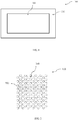
- FIG. 1 is a schematic structural view of a fine metal mask plate according to a conventional solution.
- the fine metal mask plate 100 is divided into a display region 300 and a transition display region 200.
- the display region 300 is a pixel evaporation region of the main display region of the display panel
- the transition display region 200 is a transition region of the display region 300 and the edge of the fine metal mask plate.
- the fine metal mask plate 100 is provided with openings arranged in an array for evaporating the evaporation material onto the array substrate.
- FIG. 2 is a partial enlarged view of a display region opening and a transition display region opening of a fine metal mask plate according to a conventional solution. As shown in FIG. 2 , in the conventional solution, the openings of the display region 300 and the transition display region 200 are the same, that is, the shape of the opening, the size of the opening, and the density of the openings are the same.
- the fine metal mask plate is usually fixed to a metal frame, and then the fine metal mask plate with the metal frame is fixed on the array substrate to perform evaporation in the conventional solution.
- the fine metal mask plate is usually fixed to a metal frame, and then the fine metal mask plate with the metal frame is fixed on the array substrate to perform evaporation in the conventional solution.
- the fine metal mask plate is tensioned by the restoring force due to deformation of the metal frame, so that the fine metal mask plate will not be drooped during the evaporation process.
- This process of pre-tensioning the fine metal mask plate is generally referred to as a net-extending process.
- the edge of the evaporation region is easily damaged, resulting in problems such as evaporation deviation and color mixing at the edge.
- problems such as evaporation deviation and color mixing at the edge.
- the difficulty and cost of the evaporation process are increased, and the preparation efficiency of the evaporation process is affected.
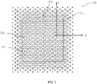
- FIG. 3 is a schematic structural view of a mask plate according to an embodiment of the present application.
- the mask plate 500 is configured to fabricate a display panel.
- the mask plate 500 includes a display region 520 and a transition display region 510.
- the display region 520 is configured to evaporate pixels to the main display region of the display panel, and the display region 520 is provided with a plurality of first through holes 521 disposed at intervals.
- the transition display region 510 is provided at a periphery of the display region 520, and the transition display region 510 is provided with a plurality of second through holes 511 arranged at intervals.
- the transition display region 510 is used for transition between the display region 520 and the edge of the mask plate 500.
- the density of the second through holes 511 is smaller than the density of the first through holes 521. That is, the percentage of the region occupied by the second through holes 511 in the transition display region 510 of the mask plate 500 is smaller than the percentage of the region occupied by the first through holes 521 in the display region 520 of the mask plate 500.
- the shape of the opening, the size of the opening, and the density of the openings of the display region 300 and the transition display region 200 are the same. Therefore, the edge of the mask plate 100 is easily damaged, resulting in a problem of uneven color development in the edge region of the display panel fabricated from the mask plate. Therefore, in the present application, the density of the second through holes 511 in the transition display region 510 is changed, and the density of the second through holes 511 in the transition display region 510 is reduced. In this way, it is helpful to increase the distance between the second through holes 511, increase the area of the connecting bridge between the second through holes 511, and increase the strength of the edge region of the mask plate 500 without affecting the display effect.
- the geometric center of each of the first through holes 521 in the display region 520 is a first hole center.
- the geometric center of each of the second through holes 511 in the transition display region 510 is a second hole center.
- the arrangement of the first hole centers in the display region is the same as the arrangement of the second hole centers in the transition display region, and apertures of the second through holes 511 is smaller than apertures of the first through holes 521. Therefore, the distance between the outer edges of the adjacent second through holes 511 is greater than the distance between the outer edges of the adjacent first through holes 521.
- the present application reduces the density of the second through holes 511 in the transition display region 510 by reducing the apertures of the second through holes 511 and increasing the distance between the outer edges of the adjacent second through holes 511.
- the area of the connecting bridge between the second through holes 511 is increased, and the strength of the edge of the mask plate 500 is increased.
- the first hole centers and the second hole centers are arranged in a row in a horizontal direction.
- the first hole centers and the second hole centers are arranged in a column in a vertical direction.
- the distances between the two adjacent first hole centers in the horizontal direction are equal, and the distances between the two adjacent first hole centers in the vertical direction are equal.
- the distances between the two adjacent second hole centers in the horizontal direction are equal, and the distances between the two adjacent first hole centers in the vertical direction are equal.
- the distance between the two adjacent first hole centers in the horizontal direction is equal to the distance between the two adjacent second hole centers in the horizontal direction.
- the distance between the two adjacent first hole centers in the vertical direction is equal to the distance between the two adjacent second hole centers in the vertical direction.
- the first hole centers and the second hole centers are arranged in an array in the same manner, except that the apertures of the second through holes 511 in the transition display region 510 are reduced, and the distance between the adjacent second through holes 511 is increased, so that the density of the second through holes 511 in the transition display region 510 is decreased.
- the present application changes the structure of the mask plate 500 simply and conveniently, and further reduces the difficulty of the fabricating process of the mask plate 500, improves the strength of the mask plate 500, and helps to improve the stability of the net-extending process.
- a direction extending away from the display region 520 in a horizontal direction is a first direction (X)
- a direction extending away from the display region 520 in a vertical direction is a second direction (Y).
- the second through holes 511 are sequentially arranged as the first column of through holes, the second column of through holes to the M-th column of through holes in the first direction, and M is a positive integer.
- the first column of through holes is a column of the second through holes closest to the display region 520 in the first direction
- the M-th column of through holes is a column of the second through holes farthest from the display region 520 in the first direction.
- the second through holes 511 are sequentially arranged as the first row of through holes, the second row of through holes to the N-th row of through holes in the second direction, and N is a positive integer.
- the first row of through holes is a row of the second through holes closest to the display region 520 in the second direction
- the N-th row of through holes is a row of the second through holes farthest from the display region 520 in the second direction.
- the apertures of the N-th row of through holes and the M-th column of through holes are at least 0.3 times of the apertures of the first through holes 521 of the display region 520, so as to avoid the apertures of the second through holes 511 at the edge of the mask plate 500 being too small, which strongly affects the display effect of the edge region.
- apertures of the first row of through holes to the N-th row of through holes are reduced according to a first predetermined rule
- apertures of the first column of through holes to the N-th column of through holes are reduced according to a second predetermined rule.
- the first predetermined rule and the second predetermined rule may be the same or different.
- the first predetermined rule may be adjusted according to the number of rows of the second through holes.
- the second predetermined rule may be adjusted according to the number of columns of the second through holes.
- the first predetermined rule is that the aperture decreases from the first row of through holes toward the N-th row of through holes
- the second predetermined rule is that the aperture decreases from the first column of through holes toward the M-th column of through holes.
- the number of rows and the number of columns of the second through holes in the transition region 510 may be the same.
- the apertures of the first row of through holes and the first column of through holes are 0.6-0.9 times of the apertures of the first through holes 521.
- the apertures of the second row of through holes and the second column of through holes are 0.3-0.6 times of the apertures of the first through holes 521.
- the apertures of the first row of through holes and the first column of through holes are 0.7-0.9 times of the apertures of the first through holes 521.
- the apertures of the second row of through holes and second column of through holes are 0.5-0.7 times of the apertures of the first through holes 521.
- the apertures of a third row of through holes and a third column of through holes are 0.3-0.5 times of the apertures of the first through holes 521.
- the apertures of the first row of through holes and the first column of through holes are 0.8-0.9 times of the apertures of the first through holes 521.
- the apertures of the second row of through holes and the second column of through holes are 0.6-0.8 times of the apertures of the first through holes 521.
- the apertures of a third row of through holes and a third column of through holes are 0.4-0.6 times of the apertures of the first through holes 521.
- the apertures of a fourth row of through holes and a fourth column of through holes are 0.3-0.4 times of the apertures of the first through holes 521.
- the apertures of the first row of the through holes and the first column of through holes are 0.8-0.9 times of the apertures of the first through holes 521.
- the apertures of the second row of through holes and the second column of through holes are 0.7-0.8 times of the apertures of the first through holes 521.
- the apertures of a third row of through holes and a third column of through holes are 0.6-0.7 times of the apertures of the first through holes 521.
- the apertures of a fourth row of through holes and a fourth column of through holes are 0.4-0.6 times of the apertures of the first through holes 521.
- the apertures of a fifth row of through holes and a fifth column of through holes are 0.3-0.4 times of the apertures of the first through holes 521.
- the number of rows and the number of columns of the second through holes in the transition display region 510 may be different.
- the variation rule of the apertures of the second through holes 511 is also different.
- the number of rows of the second through holes 511 may not be equal to the number of columns of the second through holes 511. That is, the number of rows and the number of columns of the second through holes 511 in the transition display region 510 may be different.
- the variation rule of the apertures of the second through holes 511 may refer to the above solution.
- the transition display region 510 may be arranged in three rows and four columns.
- the second through holes 511 in three rows may be disposed such that the apertures of the first row of through holes are 0.7-0.9 times of the apertures of the first through holes 521.
- the apertures of the second row of through holes are 0.5-0.7 times of the apertures of the first through holes 521.
- the apertures of a third row of through holes are 0.3-0.5 times of the apertures of the first through holes 521.
- the second through holes 511 in four columns may be disposed such that the apertures of the first column of through holes are 0.8-0.9 times of the apertures of the first through holes 521.
- the apertures of the second column of through holes are 0.6-0.8 times of the apertures of the first through holes 521.
- the apertures of a third column of through holes are 0.4-0.6 times of the apertures of the first through holes 521.
- the apertures of a fourth column of through holes are 0.3-0.4 times of the apertures of the first through holes 521.
- the present application also provides a display panel.
- the display panel includes a display substrate and pixels arranged in an array on the display substrate.
- the pixels are fabricated from the mask plate as described above.
- the display panel has high resolution and high precision of pixel evaporation, and the problem of uneven display at the edge of the display panel can be avoided.
- the design margin may be increased in the horizontal direction and the vertical direction.
- PPA pixel position accuracy
Landscapes
- Chemical & Material Sciences (AREA)
- Engineering & Computer Science (AREA)
- Organic Chemistry (AREA)
- Materials Engineering (AREA)
- Mechanical Engineering (AREA)
- Metallurgy (AREA)
- Chemical Kinetics & Catalysis (AREA)
- Physics & Mathematics (AREA)
- General Physics & Mathematics (AREA)
- Theoretical Computer Science (AREA)
- Manufacturing & Machinery (AREA)
- Electroluminescent Light Sources (AREA)
- Physical Vapour Deposition (AREA)
- Devices For Indicating Variable Information By Combining Individual Elements (AREA)
Abstract
Description
- The present application relates to the field of display technologies, and more particularly, to a display panel and a mask plate for fabrication thereof.
- With the development of display technology, the resolution of the display panel is becoming higher increasingly, and the resolution of the screen is greatly improved. As a result, the density of the pixel arrays becomes higher and higher, which presents a great challenge to the manufacturing process of a display panel. The pixel array is generally prepared by an evaporation process, for example, by accurately depositing a light-emitting layer onto a substrate through a fine metal mask plate to form a high-density pixel array. The number of openings of the mask plate is increasing, and the density of the openings is getting larger and larger, resulting in smaller and smaller distances between the openings and the strength of the mask plate is reduced.
- In order to increase the strength of the mask plate, it is a traditional solution to change the shape or arrangement of the pixels in order to achieve the purpose of increasing an area of the connecting bridge, thereby improving the strength of the mask plate. However, by changing arrangement of the pixels to increase the strength of the mask plate, the results obtained are usually limited. Moreover, in many cases, it is difficult to increase the strength of the mask plate simply and effectively for the preparation of display panel of a conventional pixel arrangement type and in the case where the arrangement of the pixels cannot be adjusted.
- Based on the above, the present application provides a display panel and a mask plate for fabricating the display panel, which can improve the strength of the edge of the mask plate, thereby improving the precision of pixel evaporation process and avoiding the problem of uneven color development at the edge of the display panel.
- The present application provides a mask plate for making a display panel. The mask plate includes:
- a display region, provided with a plurality of first through holes arranged at intervals; and
- a transition display region, disposed at a periphery of the display region, and provided with a plurality of second through holes arranged at intervals;
- a density of the second through holes is smaller than a density of the first through holes.
- According to the mask plate described above, the density of the second through holes in the transition display region on the edge is changed, and the density of the second through holes in the transition display region is reduced. In this way, it is helpful to increase the distance between the second through holes, the area of the connecting bridge between the second through holes, and the strength of the edge region of the mask plate without affecting the display effect.
- In one of the embodiments, a geometric center of each of the first through holes is a first hole center, and a geometric center of each of the second through holes is a second hole center;
the arrangement of the first hole centers in the display region is the same as the arrangement of the second hole centers in the transition display region; and
apertures of the second through holes are smaller than apertures of the first through holes. - In one of the embodiments, the first hole centers and the second hole centers are arranged in a row in a horizontal direction, and the first hole centers and the second hole centers are arranged in a column in a vertical direction;
distances between two adjacent first hole centers in the horizontal direction are equal, and distances between two adjacent first hole centers in the vertical direction are equal; and
distances between two adjacent second hole centers in the horizontal direction are equal, and distances between two adjacent first hole centers in the vertical direction are equal. - In one of the embodiments, a distance between the two adjacent first hole centers in the horizontal direction is equal to a distance between the two adjacent second hole centers in the horizontal direction; and a distance between the two adjacent first hole centers in the vertical direction is equal to a distance between the two adjacent second hole centers in the vertical direction.
- In one of the embodiments, a row of the second through holes closest to the display region is a first row of through holes of the transition display region, with sequentially a second row to an N-th row of through holes of the transition display region provided along a direction away from the display region, and N being a positive integer;
a column of the second through holes closest to the display region is a first column of through holes of the transition display region, with sequentially a second column to an M-th column of through holes of the transition display region provided along a direction away from the display region, and M being a positive integer; and
apertures of the N-th row of through holes and the M-th column of through holes are at least 0.3 times of the apertures of the first through holes. - In one of the embodiments, apertures of the first row of through holes to the N-th row of through holes are reduced according to a first predetermined rule, and apertures of the first column of through holes to the M-th column of through holes are reduced according to a second predetermined rule.
- In one of the embodiments, the number of rows and the number of columns of the second through holes are the same.
- In one of the embodiments, when two rows and two columns of the second through holes are provided,
the apertures of the first row of through holes and the first column of through holes are 0.6-0.9 times of the apertures of the first through holes; and
the apertures of the second row of through holes and the second column of through holes are 0.3-0.6 times of the apertures of the first through holes. - In one of the embodiments, when three rows and three columns of the second through holes are provided,
the apertures of the first row of through holes and the first column of through holes are 0.7-0.9 times of the apertures of the first through holes;
the apertures of the second row of through holes and the second column of through holes are 0.5-0.7 times of the apertures of the first through holes; and
apertures of a third row of through holes and a third column of through holes are 0.3-0.5 times of the apertures of the first through holes. - In one of the embodiments, when four rows and four columns of the second through holes are provided,
the apertures of the first row of through holes and the first column of through holes are 0.8-0.9 times of the apertures of the first through holes;
the apertures of the second row of through holes and the second column of through holes are 0.6-0.8 times of the apertures of the first through holes.
apertures of a third row of through holes and a third column of through holes are 0.4-0.6 times of the apertures of the first through holes; and
apertures of a fourth row of through holes and a fourth column of through holes are 0.3-0.4 times of the apertures of the first through holes. - In one of the embodiments, when five rows and five columns of the second through holes are provided,
the apertures of the first row of through holes and the first column of through holes are 0.8-0.9 times of the apertures of the first through holes;
the apertures of the second row of through holes and the second column of through holes are 0.7-0.8 times of the apertures of the first through holes;
apertures of a third row of through holes and a third column of through holes are 0.6-0.7 times of the apertures of the first through holes;
apertures of a fourth row of through holes and a fourth column of through holes are 0.4-0.6 times of the apertures of the first through holes; and
apertures of a fifth row of through holes and a fifth column of through holes are 0.3-0.4 times of the apertures of the first through holes. - In one of the embodiments, the number of rows and the number of columns of the second through holes are different.
- In one of the embodiments, when three rows and four columns of the second through holes are provided,
the apertures of the first row of through holes are 0.7-0.9 times of the apertures of the first through hole; the apertures of the second row of through holes are 0.5-0.7 times of the apertures of the first through holes; apertures of a third row of through holes are 0.3-0.5 times of the apertures of the first through holes; and
the apertures of the first column of through holes are 0.8-0.9 times of the apertures of the first through holes; the apertures of the second column of through holes are 0.6-0.8 times of the apertures of the first through holes; apertures of a third column of through holes are 0.4-0.6 times of the apertures of the first through holes; and apertures of a fourth column of through holes are 0.3-0.4 times of the apertures of the first through holes. - The present application also provides a display panel. The display panel includes:
- a display substrate; and
- pixels arranged in an array on the display substrate; and
- the pixels are fabricated from the mask plate as described above.
- To illustrate the technical solutions according to the embodiments of the present application or in the prior art more clearly, the accompanying drawings for describing the embodiments or the prior art are introduced briefly in the following. Apparently, the accompanying drawings in the following description are only some embodiments of the present application, and persons of ordinary skill in the art can derive other drawings from the accompanying drawings without creative efforts.
-
FIG. 1 is a schematic structural view of a fine metal mask plate according to a conventional solution. -
FIG. 2 is a partial enlarged view of a display region opening and a transition display region opening of a fine metal mask plate according to a conventional solution. -
FIG. 3 is a schematic structural view of a mask plate according to an embodiment of the present application. - In order to more clearly illustrate the embodiments of the present application or the technical solutions in the prior art, drawings used in the embodiments or the prior art description will be briefly introduced below. It is obvious that the drawings in the following description are only some of the embodiments of the present application, and those skilled in the art can obtain the drawings of other embodiments according to the above drawings without any creative work.
- When fabricating the pixels on the display panel, each layer of the material of the pixels needs to be evaporated onto the array substrate by an evaporation process. In the evaporation process, a corresponding fine metal mask plate is required. Since a high temperature is generated during the evaporation process, the fine metal mask plate may occur a thermally expansion at this point, resulting in the fine metal mask plate being drooped under the effect of gravity, so that the geometry of the fine metal mask plate is changed, and the evaporation material cannot be evaporated to a specified position, which affects the evaporation precision, resulting in display unevenness and color mixing of the fabricated display panel.
-
FIG. 1 is a schematic structural view of a fine metal mask plate according to a conventional solution. As shown inFIG. 1 , the finemetal mask plate 100 is divided into adisplay region 300 and atransition display region 200. Thedisplay region 300 is a pixel evaporation region of the main display region of the display panel, and thetransition display region 200 is a transition region of thedisplay region 300 and the edge of the fine metal mask plate. The finemetal mask plate 100 is provided with openings arranged in an array for evaporating the evaporation material onto the array substrate.FIG. 2 is a partial enlarged view of a display region opening and a transition display region opening of a fine metal mask plate according to a conventional solution. As shown inFIG. 2 , in the conventional solution, the openings of thedisplay region 300 and thetransition display region 200 are the same, that is, the shape of the opening, the size of the opening, and the density of the openings are the same. - In order to avoid the problem that the fine metal mask plate is easily deformed in the evaporation process, the fine metal mask plate is usually fixed to a metal frame, and then the fine metal mask plate with the metal frame is fixed on the array substrate to perform evaporation in the conventional solution. Specifically, when fixing the fine metal mask plate in the metal frame, it is necessary to choose an appropriate force firstly to stretch the fine metal mask plate, then an appropriate antagonistic force is applied to the metal frame to deform the metal frame, and finally, the stretched fine metal mask plate is fixed on the metal frame that the antagonistic force is applied. In this way, the fine metal mask plate is tensioned by the restoring force due to deformation of the metal frame, so that the fine metal mask plate will not be drooped during the evaporation process. This process of pre-tensioning the fine metal mask plate is generally referred to as a net-extending process.
- Generally, in order to improve the precision of evaporation, it is necessary to perform a PPA (pixel position accuracy) test on the fine metal mask plate, so as to realize positioning of the fine metal mask plate and the array substrate in the conventional solution. Therefore, in the net-extending process, it is necessary to find an appropriate stretching force and an antagonistic force for deforming the metal frame, and to adjust the strength through a test for a real object so as to meet the precision requirement of the evaporation. However, since the opening of the fine metal mask plate are denser and denser, the distance between the openings, that is, the size of the connecting bridge between the openings, becomes smaller and smaller, the fine metal mask plate is easily damaged in the net-extending process, especially at the fixed edge. Due to the relatively concentrated force, the edge of the evaporation region is easily damaged, resulting in problems such as evaporation deviation and color mixing at the edge. Thus, the difficulty and cost of the evaporation process are increased, and the preparation efficiency of the evaporation process is affected.
- In order to increase the strength of the mask plate, the present application provides a mask plate with a special structure. The mask plate according to the present application has high strength, thereby improving the precision of pixel evaporation and avoiding the problem of uneven color development at the edge of the display panel.
FIG. 3 is a schematic structural view of a mask plate according to an embodiment of the present application. As shown inFIG. 3 , themask plate 500 is configured to fabricate a display panel. Themask plate 500 includes adisplay region 520 and atransition display region 510. Thedisplay region 520 is configured to evaporate pixels to the main display region of the display panel, and thedisplay region 520 is provided with a plurality of first throughholes 521 disposed at intervals. Thetransition display region 510 is provided at a periphery of thedisplay region 520, and thetransition display region 510 is provided with a plurality of second throughholes 511 arranged at intervals. Thetransition display region 510 is used for transition between thedisplay region 520 and the edge of themask plate 500. The density of the second throughholes 511 is smaller than the density of the first throughholes 521. That is, the percentage of the region occupied by the second throughholes 511 in thetransition display region 510 of themask plate 500 is smaller than the percentage of the region occupied by the first throughholes 521 in thedisplay region 520 of themask plate 500. - It should be understood that, in the conventional solution, as shown in
FIG. 2 , the shape of the opening, the size of the opening, and the density of the openings of thedisplay region 300 and thetransition display region 200 are the same. Therefore, the edge of themask plate 100 is easily damaged, resulting in a problem of uneven color development in the edge region of the display panel fabricated from the mask plate. Therefore, in the present application, the density of the second throughholes 511 in thetransition display region 510 is changed, and the density of the second throughholes 511 in thetransition display region 510 is reduced. In this way, it is helpful to increase the distance between the second throughholes 511, increase the area of the connecting bridge between the second throughholes 511, and increase the strength of the edge region of themask plate 500 without affecting the display effect. - In an embodiment, the geometric center of each of the first through
holes 521 in thedisplay region 520 is a first hole center. The geometric center of each of the second throughholes 511 in thetransition display region 510 is a second hole center. The arrangement of the first hole centers in the display region is the same as the arrangement of the second hole centers in the transition display region, and apertures of the second throughholes 511 is smaller than apertures of the first throughholes 521. Therefore, the distance between the outer edges of the adjacent second throughholes 511 is greater than the distance between the outer edges of the adjacent first throughholes 521. - The present application reduces the density of the second through
holes 511 in thetransition display region 510 by reducing the apertures of the second throughholes 511 and increasing the distance between the outer edges of the adjacent second throughholes 511. Thus, the area of the connecting bridge between the second throughholes 511 is increased, and the strength of the edge of themask plate 500 is increased. - In an embodiment, the first hole centers and the second hole centers are arranged in a row in a horizontal direction. The first hole centers and the second hole centers are arranged in a column in a vertical direction. The distances between the two adjacent first hole centers in the horizontal direction are equal, and the distances between the two adjacent first hole centers in the vertical direction are equal. The distances between the two adjacent second hole centers in the horizontal direction are equal, and the distances between the two adjacent first hole centers in the vertical direction are equal. The distance between the two adjacent first hole centers in the horizontal direction is equal to the distance between the two adjacent second hole centers in the horizontal direction. The distance between the two adjacent first hole centers in the vertical direction is equal to the distance between the two adjacent second hole centers in the vertical direction. That is, the first hole centers and the second hole centers are arranged in an array in the same manner, except that the apertures of the second through
holes 511 in thetransition display region 510 are reduced, and the distance between the adjacent second throughholes 511 is increased, so that the density of the second throughholes 511 in thetransition display region 510 is decreased. The present application changes the structure of themask plate 500 simply and conveniently, and further reduces the difficulty of the fabricating process of themask plate 500, improves the strength of themask plate 500, and helps to improve the stability of the net-extending process. - As shown in
FIG. 3 , in an embodiment, a direction extending away from thedisplay region 520 in a horizontal direction is a first direction (X), and a direction extending away from thedisplay region 520 in a vertical direction is a second direction (Y). The second throughholes 511 are sequentially arranged as the first column of through holes, the second column of through holes to the M-th column of through holes in the first direction, and M is a positive integer. The first column of through holes is a column of the second through holes closest to thedisplay region 520 in the first direction, and the M-th column of through holes is a column of the second through holes farthest from thedisplay region 520 in the first direction. The second throughholes 511 are sequentially arranged as the first row of through holes, the second row of through holes to the N-th row of through holes in the second direction, and N is a positive integer. The first row of through holes is a row of the second through holes closest to thedisplay region 520 in the second direction, and the N-th row of through holes is a row of the second through holes farthest from thedisplay region 520 in the second direction. The apertures of the N-th row of through holes and the M-th column of through holes are at least 0.3 times of the apertures of the first throughholes 521 of thedisplay region 520, so as to avoid the apertures of the second throughholes 511 at the edge of themask plate 500 being too small, which strongly affects the display effect of the edge region. - In an embodiment, apertures of the first row of through holes to the N-th row of through holes are reduced according to a first predetermined rule, and apertures of the first column of through holes to the N-th column of through holes are reduced according to a second predetermined rule. The first predetermined rule and the second predetermined rule may be the same or different. The first predetermined rule may be adjusted according to the number of rows of the second through holes. The second predetermined rule may be adjusted according to the number of columns of the second through holes. For example, the first predetermined rule is that the aperture decreases from the first row of through holes toward the N-th row of through holes, and the second predetermined rule is that the aperture decreases from the first column of through holes toward the M-th column of through holes.
- In an embodiment, the number of rows and the number of columns of the second through holes in the
transition region 510 may be the same. - In an embodiment, when two rows and two columns of the second through
holes 511 are provided, the apertures of the first row of through holes and the first column of through holes are 0.6-0.9 times of the apertures of the first throughholes 521. The apertures of the second row of through holes and the second column of through holes are 0.3-0.6 times of the apertures of the first throughholes 521. - In an embodiment, when three rows and three columns of the second through
holes 511 are provided, the apertures of the first row of through holes and the first column of through holes are 0.7-0.9 times of the apertures of the first throughholes 521. The apertures of the second row of through holes and second column of through holes are 0.5-0.7 times of the apertures of the first throughholes 521. The apertures of a third row of through holes and a third column of through holes are 0.3-0.5 times of the apertures of the first throughholes 521. - In an embodiment, when four rows and four columns of the second through
holes 511 are provided, the apertures of the first row of through holes and the first column of through holes are 0.8-0.9 times of the apertures of the first throughholes 521. The apertures of the second row of through holes and the second column of through holes are 0.6-0.8 times of the apertures of the first throughholes 521. The apertures of a third row of through holes and a third column of through holes are 0.4-0.6 times of the apertures of the first throughholes 521. The apertures of a fourth row of through holes and a fourth column of through holes are 0.3-0.4 times of the apertures of the first throughholes 521. - In an embodiment, when five rows and five columns of the second through
holes 511 are provided, the apertures of the first row of the through holes and the first column of through holes are 0.8-0.9 times of the apertures of the first throughholes 521. The apertures of the second row of through holes and the second column of through holes are 0.7-0.8 times of the apertures of the first throughholes 521. The apertures of a third row of through holes and a third column of through holes are 0.6-0.7 times of the apertures of the first throughholes 521. The apertures of a fourth row of through holes and a fourth column of through holes are 0.4-0.6 times of the apertures of the first throughholes 521. The apertures of a fifth row of through holes and a fifth column of through holes are 0.3-0.4 times of the apertures of the first throughholes 521. - In the present application, the number of rows and the number of columns of the second through holes in the
transition display region 510 may be different. In the case where the number of rows and the number of columns are different, the variation rule of the apertures of the second throughholes 511 is also different. Through providing an optimum gradation rule with the apertures of the second throughholes 511 having different number of rows and columns, an optimum transition for the display effect of thetransition display region 510 may be achieved. - In an embodiment, the number of rows of the second through
holes 511 may not be equal to the number of columns of the second throughholes 511. That is, the number of rows and the number of columns of the second throughholes 511 in thetransition display region 510 may be different. When a different number of rows or columns are provided, the variation rule of the apertures of the second throughholes 511 may refer to the above solution. For example, thetransition display region 510 may be arranged in three rows and four columns. The second throughholes 511 in three rows may be disposed such that the apertures of the first row of through holes are 0.7-0.9 times of the apertures of the first throughholes 521. The apertures of the second row of through holes are 0.5-0.7 times of the apertures of the first throughholes 521. The apertures of a third row of through holes are 0.3-0.5 times of the apertures of the first throughholes 521. The second throughholes 511 in four columns may be disposed such that the apertures of the first column of through holes are 0.8-0.9 times of the apertures of the first throughholes 521. The apertures of the second column of through holes are 0.6-0.8 times of the apertures of the first throughholes 521. The apertures of a third column of through holes are 0.4-0.6 times of the apertures of the first throughholes 521. The apertures of a fourth column of through holes are 0.3-0.4 times of the apertures of the first throughholes 521. - The present application also provides a display panel. The display panel includes a display substrate and pixels arranged in an array on the display substrate. The pixels are fabricated from the mask plate as described above. The display panel has high resolution and high precision of pixel evaporation, and the problem of uneven display at the edge of the display panel can be avoided.
- According to the
mask plate 500 of the present application, the design margin may be increased in the horizontal direction and the vertical direction. The result of PPA (pixel position accuracy) testing of the mask plate of the present application is superior to that of the conventional solution. The strength of themask plate 100 is improved, and the problem of uneven color development at the edge of the display panel is also reduced significantly. - The technical features of the above-mentioned embodiments may be combined in any combination. For the sake of brevity of description, all possible combinations of the technical features in the above embodiments are not described. However, the respective technical features mentioned in the same embodiment can also be combined arbitrarily as long as they have no collision with each other.
- The above-described embodiments are merely illustrative of several embodiments of the present application, and the description thereof is more specific and detailed, but is not to be construed as limiting the scope of the invention. It should be noted that a number of variations and modifications may be made by those skilled in the art without departing from the spirit and scope of the present application. Therefore, the scope of protection of this application should be determined by the appended claims.
Claims (14)
- A mask plate for making a display panel, comprising:a display region provided with a plurality of first through holes arranged at intervals; anda transition display region disposed at a periphery of the display region, and provided with a plurality of second through holes arranged at intervals,a density of the second through holes being smaller than a density of the first through holes.
- The mask plate according to claim 1, wherein:a geometric center of each of the first through holes is a first hole center, and a geometric center of the second through holes is a second hole center;the arrangement of the first hole centers in the display region is same to the arrangement of the second hole centers in the transition display region; andapertures of the second through holes are smaller than apertures of the first through holes.
- The mask plate according to claim 2, wherein:the first hole centers and the second hole centers are arranged in a row in a horizontal direction, and the first hole centers and the second hole centers are arranged in a column in a vertical direction;distances between two adjacent first hole centers in the horizontal direction are equal, and distances between two adjacent first hole centers in the vertical direction are equal; anddistances between two adjacent second hole centers in the horizontal direction are equal, and distances between two adjacent first hole centers in the vertical direction are equal.
- The mask plate according to claim 3, wherein a distance between the two adjacent first hole centers in the horizontal direction is equal to a distance between the two adjacent second hole centers in the horizontal direction; and a distance between the two adjacent first hole centers in the vertical direction is equal to a distance between the two adjacent second hole centers in the vertical direction.
- The mask plate according to claim 4, wherein:a row of the second through holes closest to the display region is a first row of through holes of the transition display region, with sequentially a second row to an N-th row of through holes of the transition display region provided along a direction away from the display region, and N being a positive integer;a column of the second through holes closest to the display region is a first column of through holes of the transition display region, with sequentially a second column to an M-th column of through holes of the transition display region provided along a direction away from the display region, and M being a positive integer; andapertures of the N-th row of through holes and the M-th column of through holes are at least 0.3 times of the apertures of the first through holes.
- The mask plate according to claim 5, wherein apertures of the first row of through holes to the N-th row of through holes are reduced according to a first predetermined rule, and apertures of the first column of through holes to the M-th column of through holes are reduced according to a second predetermined rule.
- The mask plate according to claim 6, wherein the number of rows and the number of columns of the second through holes are the same.
- The mask plate according to claim 7, wherein
when two rows and two columns of the second through holes are provided,
the apertures of the first row of through holes and the first column of through holes are 0.6-0.9 times of the apertures of the first through holes; and
the apertures of the second row of through holes and the second column of through holes are 0.3-0.6 times of the apertures of the first through holes. - The mask plate according to claim 7, wherein
when three rows and three columns of the second through holes are provided,
the apertures of the first row of through holes and the first column of through holes are 0.7-0.9 times of the apertures of the first through holes;
the apertures of the second row of through holes and the second column of through holes are 0.5-0.7 times of the apertures of the first through holes; and
apertures of a third row of through holes and a third column of through holes are 0.3-0.5 times of the apertures of the first through holes. - The mask plate according to claim 7, wherein
when four rows and four columns of the second through holes are provided,
the apertures of the first row of through holes and the first column of through holes are 0.8-0.9 times of the apertures of the first through holes;
the apertures of the second row of through holes and the second column of through holes are 0.6-0.8 times of the apertures of the first through holes;
apertures of a third row of through holes and a third column of through holes are 0.4-0.6 times of the apertures of the first through holes; and
apertures of a fourth row of through holes and a fourth column of through holes are 0.3-0.4 times of the apertures of the first through holes. - The mask plate according to claim 7, wherein
when five rows and five columns of the second through holes are provided,
the apertures of the first row of through holes and the first column of through holes are 0.8-0.9 times of the apertures of the first through holes;
the apertures of the second row of through holes and the second column of through holes are 0.7-0.8 times of the apertures of the first through holes;
apertures of a third row of through holes and a third column of through holes are 0.6-0.7 times of the apertures of the first through holes;
apertures of a fourth row of through holes and a fourth column of through holes are 0.4-0.6 times of the apertures of the first through holes; and
apertures of a fifth row of through holes and a fifth column of through holes are 0.3-0.4 times of the apertures of the first through holes. - The mask plate according to claim 6, wherein the number of rows and the number of columns of the second through holes are different.
- The mask plate according to claim 12, wherein
when three rows and four columns of the second through holes are provided,
the apertures of the first row of through holes are 0.7-0.9 times of the apertures of the first through hole; the apertures of the second row of through holes are 0.5-0.7 times of the apertures of the first through hole; apertures of a third row of through holes are 0.3-0.5 times of the apertures of the first through holes; and
the apertures of the first column of through holes are 0.8-0.9 times of the apertures of the first through holes; the apertures of the second column of through holes are 0.6-0.8 times of the apertures of the first through holes; apertures of a third column of through holes are 0.4-0.6 times of the apertures of the first through holes; and apertures of a fourth column of through holes are 0.3-0.4 times of the apertures of the first through holes. - A display panel, comprising:a display substrate; andpixels arranged in an array on the display substrate;wherein the pixels are fabricated from the mask plate of any one of claims 1-13.
Applications Claiming Priority (2)
| Application Number | Priority Date | Filing Date | Title |
|---|---|---|---|
| CN201820471716.3U CN208013662U (en) | 2018-03-30 | 2018-03-30 | Display panel and making display panel mask plate |
| PCT/CN2018/102547 WO2019184224A1 (en) | 2018-03-30 | 2018-08-27 | Display panel and mask plate used for manufacturing display panel |
Publications (2)
| Publication Number | Publication Date |
|---|---|
| EP3623866A1 true EP3623866A1 (en) | 2020-03-18 |
| EP3623866A4 EP3623866A4 (en) | 2020-07-29 |
Family
ID=63892167
Family Applications (1)
| Application Number | Title | Priority Date | Filing Date |
|---|---|---|---|
| EP18912132.0A Pending EP3623866A4 (en) | 2018-03-30 | 2018-08-27 | DISPLAY PANEL AND MASK PLATE FOR PRODUCING A DISPLAY PANEL |
Country Status (7)
| Country | Link |
|---|---|
| US (1) | US20210363626A1 (en) |
| EP (1) | EP3623866A4 (en) |
| JP (1) | JP2020524218A (en) |
| KR (1) | KR20200011047A (en) |
| CN (1) | CN208013662U (en) |
| TW (1) | TWM570537U (en) |
| WO (1) | WO2019184224A1 (en) |
Families Citing this family (10)
| Publication number | Priority date | Publication date | Assignee | Title |
|---|---|---|---|---|
| CN109207920B (en) | 2018-11-12 | 2021-02-09 | 京东方科技集团股份有限公司 | Mask plate |
| CN109487206B (en) * | 2018-12-11 | 2020-08-11 | 武汉华星光电半导体显示技术有限公司 | Mask and mask device adopting same |
| CN109722630B (en) * | 2019-01-09 | 2020-01-14 | 昆山工研院新型平板显示技术中心有限公司 | Mask unit and mask plate assembly with same |
| CN109504938B (en) * | 2019-01-09 | 2020-04-17 | 昆山国显光电有限公司 | Mask unit, manufacturing method thereof and mask |
| CN110760790A (en) * | 2019-02-28 | 2020-02-07 | 云谷(固安)科技有限公司 | Mask plate and mask assembly |
| CN110335888A (en) * | 2019-04-24 | 2019-10-15 | 深圳市华星光电半导体显示技术有限公司 | Display panel and display device |
| US11024584B2 (en) * | 2019-05-29 | 2021-06-01 | Innolux Corporation | Electronic device |
| CN111834395A (en) * | 2019-09-30 | 2020-10-27 | 昆山国显光电有限公司 | Transparent display panel, display device and display panel thereof |
| CN110718578B (en) * | 2019-10-31 | 2022-10-21 | 武汉天马微电子有限公司 | Display panel, preparation method thereof, display device and mask plate |
| CN114761605B (en) * | 2020-10-28 | 2024-02-13 | 京东方科技集团股份有限公司 | Mask plate and preparation method thereof, display panel and preparation method thereof, display device |
Family Cites Families (11)
| Publication number | Priority date | Publication date | Assignee | Title |
|---|---|---|---|---|
| WO2012059837A1 (en) * | 2010-11-04 | 2012-05-10 | Koninklijke Philips Electronics N.V. | Solid state light emitting devices based on crystallographically relaxed structures |
| KR102024853B1 (en) * | 2012-09-03 | 2019-11-05 | 삼성디스플레이 주식회사 | Mask and mask assembly |
| CN103589995B (en) * | 2013-10-09 | 2018-04-27 | 昆山允升吉光电科技有限公司 | A kind of production method of mask plate |
| JP2015103427A (en) * | 2013-11-26 | 2015-06-04 | 株式会社ジャパンディスプレイ | Manufacturing method of display device |
| CN103695842B (en) * | 2013-12-31 | 2015-12-09 | 信利半导体有限公司 | A kind of mask plate and preparation method thereof |
| KR102311586B1 (en) * | 2014-12-26 | 2021-10-12 | 삼성디스플레이 주식회사 | Apparatus for deposition and substrate alignment method in the same |
| CN105589274B (en) * | 2016-03-11 | 2019-03-26 | 厦门天马微电子有限公司 | Mask plate, array substrate, liquid crystal display device and method for forming through holes |
| JP2017222064A (en) * | 2016-06-14 | 2017-12-21 | 株式会社リコー | Power supply control device, droplet discharge device, power supply control method, and power supply control program |
| JP7121918B2 (en) * | 2016-12-14 | 2022-08-19 | 大日本印刷株式会社 | Evaporation mask device and method for manufacturing evaporation mask device |
| CN107460436A (en) * | 2017-07-25 | 2017-12-12 | 武汉华星光电半导体显示技术有限公司 | Metal otter board and evaporation mask device |
| CN107435131B (en) * | 2017-09-29 | 2019-08-02 | 上海天马微电子有限公司 | Mask device, evaporation equipment and method for manufacturing mask device |
-
2018
- 2018-03-30 CN CN201820471716.3U patent/CN208013662U/en active Active
- 2018-08-27 KR KR1020207000950A patent/KR20200011047A/en not_active Ceased
- 2018-08-27 JP JP2019570531A patent/JP2020524218A/en active Pending
- 2018-08-27 US US16/333,229 patent/US20210363626A1/en not_active Abandoned
- 2018-08-27 EP EP18912132.0A patent/EP3623866A4/en active Pending
- 2018-08-27 WO PCT/CN2018/102547 patent/WO2019184224A1/en not_active Ceased
- 2018-09-12 TW TW107212430U patent/TWM570537U/en unknown
Also Published As
| Publication number | Publication date |
|---|---|
| US20210363626A1 (en) | 2021-11-25 |
| WO2019184224A1 (en) | 2019-10-03 |
| CN208013662U (en) | 2018-10-26 |
| JP2020524218A (en) | 2020-08-13 |
| EP3623866A4 (en) | 2020-07-29 |
| TWM570537U (en) | 2018-11-21 |
| KR20200011047A (en) | 2020-01-31 |
Similar Documents
| Publication | Publication Date | Title |
|---|---|---|
| US20210363626A1 (en) | Display panel and mask plate for fabricating the same | |
| US12089466B2 (en) | Display panel having five first, four second and four third sub-pixels arranged in a virtual rectangle with five first sub-pixels having different areas from each other and four third sub-pixels having different areas from each other | |
| US10934613B2 (en) | Mask plate, mask plate assembly including mask plate and method for manufacturing same | |
| US20220056573A1 (en) | Mask | |
| CN112313802B (en) | Display substrate, fine metal mask set and manufacturing method | |
| US11066738B2 (en) | Mask plates and display panels | |
| CN105568217B (en) | Metal mask plate and preparation method thereof | |
| US12043889B2 (en) | Mask plate, method for fabricating the same, and mask plate assembly | |
| US7934968B2 (en) | Method of fabricating pixel structure | |
| WO2019201170A1 (en) | Pixel arrangement structure, display panel, mask assembly, and vapor deposition device | |
| US10658591B2 (en) | Method for producing deposition mask | |
| WO2017185769A1 (en) | Pixel array and manufacturing method therefor, and organic light emitting diode array substrate | |
| US11950477B2 (en) | OLED display panel and OLED display device | |
| WO2021036067A1 (en) | Mask plate and manufacturing method therefor, fine metal mask plate, mask device and use method thereof | |
| WO2021046807A1 (en) | Mask device and manufacturing method therefor, evaporation method and display device | |
| US20210336147A1 (en) | Mask | |
| US20140065355A1 (en) | Mask and mask assembly | |
| KR20180127257A (en) | Ultrafine Precision Metal Mask with Multi-Structure with Frame Sheet and Manufacturing Method Thereof | |
| US20140251210A1 (en) | Mask structure, mask assembly including the same, and mask structure manufacturing method | |
| US20190292647A1 (en) | Masks and display devices | |
| US12065726B2 (en) | Mask assembly and manufacturing method thereof | |
| CN212412057U (en) | Display panel, mask assembly and display device | |
| KR102192036B1 (en) | Mask open area processing method of open mask assembly | |
| KR101986526B1 (en) | Producing method of mask | |
| CN113215529A (en) | Precision mask plate and mask plate assembly |
Legal Events
| Date | Code | Title | Description |
|---|---|---|---|
| STAA | Information on the status of an ep patent application or granted ep patent |
Free format text: STATUS: THE INTERNATIONAL PUBLICATION HAS BEEN MADE |
|
| PUAI | Public reference made under article 153(3) epc to a published international application that has entered the european phase |
Free format text: ORIGINAL CODE: 0009012 |
|
| STAA | Information on the status of an ep patent application or granted ep patent |
Free format text: STATUS: REQUEST FOR EXAMINATION WAS MADE |
|
| 17P | Request for examination filed |
Effective date: 20191212 |
|
| AK | Designated contracting states |
Kind code of ref document: A1 Designated state(s): AL AT BE BG CH CY CZ DE DK EE ES FI FR GB GR HR HU IE IS IT LI LT LU LV MC MK MT NL NO PL PT RO RS SE SI SK SM TR |
|
| AX | Request for extension of the european patent |
Extension state: BA ME |
|
| A4 | Supplementary search report drawn up and despatched |
Effective date: 20200629 |
|
| RIC1 | Information provided on ipc code assigned before grant |
Ipc: G09F 9/00 20060101ALI20200623BHEP Ipc: G03F 1/00 20120101AFI20200623BHEP Ipc: C23C 14/04 20060101ALI20200623BHEP |
|
| DAV | Request for validation of the european patent (deleted) | ||
| DAX | Request for extension of the european patent (deleted) | ||
| STAA | Information on the status of an ep patent application or granted ep patent |
Free format text: STATUS: EXAMINATION IS IN PROGRESS |
|
| 17Q | First examination report despatched |
Effective date: 20231106 |