EP3623705B1 - Gargerät - Google Patents
Gargerät Download PDFInfo
- Publication number
- EP3623705B1 EP3623705B1 EP19196184.6A EP19196184A EP3623705B1 EP 3623705 B1 EP3623705 B1 EP 3623705B1 EP 19196184 A EP19196184 A EP 19196184A EP 3623705 B1 EP3623705 B1 EP 3623705B1
- Authority
- EP
- European Patent Office
- Prior art keywords
- cooling
- heat
- cooking appliance
- housing
- appliance according
- Prior art date
- Legal status (The legal status is an assumption and is not a legal conclusion. Google has not performed a legal analysis and makes no representation as to the accuracy of the status listed.)
- Active
Links
Images



Classifications
-
- F—MECHANICAL ENGINEERING; LIGHTING; HEATING; WEAPONS; BLASTING
- F24—HEATING; RANGES; VENTILATING
- F24C—DOMESTIC STOVES OR RANGES ; DETAILS OF DOMESTIC STOVES OR RANGES, OF GENERAL APPLICATION
- F24C7/00—Stoves or ranges heated by electric energy
- F24C7/08—Arrangement or mounting of control or safety devices
- F24C7/082—Arrangement or mounting of control or safety devices on ranges, e.g. control panels, illumination
-
- F—MECHANICAL ENGINEERING; LIGHTING; HEATING; WEAPONS; BLASTING
- F24—HEATING; RANGES; VENTILATING
- F24C—DOMESTIC STOVES OR RANGES ; DETAILS OF DOMESTIC STOVES OR RANGES, OF GENERAL APPLICATION
- F24C15/00—Details
- F24C15/006—Arrangements for circulation of cooling air
-
- A—HUMAN NECESSITIES
- A21—BAKING; EDIBLE DOUGHS
- A21B—BAKERS' OVENS; MACHINES OR EQUIPMENT FOR BAKING
- A21B3/00—Parts or accessories of ovens
-
- A—HUMAN NECESSITIES
- A47—FURNITURE; DOMESTIC ARTICLES OR APPLIANCES; COFFEE MILLS; SPICE MILLS; SUCTION CLEANERS IN GENERAL
- A47J—KITCHEN EQUIPMENT; COFFEE MILLS; SPICE MILLS; APPARATUS FOR MAKING BEVERAGES
- A47J27/00—Cooking-vessels
- A47J27/14—Cooking-vessels for use in hotels, restaurants, or canteens
-
- A—HUMAN NECESSITIES
- A47—FURNITURE; DOMESTIC ARTICLES OR APPLIANCES; COFFEE MILLS; SPICE MILLS; SUCTION CLEANERS IN GENERAL
- A47J—KITCHEN EQUIPMENT; COFFEE MILLS; SPICE MILLS; APPARATUS FOR MAKING BEVERAGES
- A47J36/00—Parts, details or accessories of cooking-vessels
- A47J36/32—Time-controlled igniting mechanisms or alarm devices
-
- G—PHYSICS
- G01—MEASURING; TESTING
- G01D—MEASURING NOT SPECIALLY ADAPTED FOR A SPECIFIC VARIABLE; ARRANGEMENTS FOR MEASURING TWO OR MORE VARIABLES NOT COVERED IN A SINGLE OTHER SUBCLASS; TARIFF METERING APPARATUS; MEASURING OR TESTING NOT OTHERWISE PROVIDED FOR
- G01D11/00—Component parts of measuring arrangements not specially adapted for a specific variable
- G01D11/24—Housings ; Casings for instruments
- G01D11/245—Housings for sensors
-
- H—ELECTRICITY
- H05—ELECTRIC TECHNIQUES NOT OTHERWISE PROVIDED FOR
- H05K—PRINTED CIRCUITS; CASINGS OR CONSTRUCTIONAL DETAILS OF ELECTRIC APPARATUS; MANUFACTURE OF ASSEMBLAGES OF ELECTRICAL COMPONENTS
- H05K7/00—Constructional details common to different types of electric apparatus
- H05K7/20—Modifications to facilitate cooling, ventilating, or heating
- H05K7/20009—Modifications to facilitate cooling, ventilating, or heating using a gaseous coolant in electronic enclosures
- H05K7/20136—Forced ventilation, e.g. by fans
- H05K7/20154—Heat dissipaters coupled to components
-
- H—ELECTRICITY
- H05—ELECTRIC TECHNIQUES NOT OTHERWISE PROVIDED FOR
- H05K—PRINTED CIRCUITS; CASINGS OR CONSTRUCTIONAL DETAILS OF ELECTRIC APPARATUS; MANUFACTURE OF ASSEMBLAGES OF ELECTRICAL COMPONENTS
- H05K7/00—Constructional details common to different types of electric apparatus
- H05K7/20—Modifications to facilitate cooling, ventilating, or heating
- H05K7/20009—Modifications to facilitate cooling, ventilating, or heating using a gaseous coolant in electronic enclosures
- H05K7/20136—Forced ventilation, e.g. by fans
- H05K7/20172—Fan mounting or fan specifications
-
- H—ELECTRICITY
- H05—ELECTRIC TECHNIQUES NOT OTHERWISE PROVIDED FOR
- H05K—PRINTED CIRCUITS; CASINGS OR CONSTRUCTIONAL DETAILS OF ELECTRIC APPARATUS; MANUFACTURE OF ASSEMBLAGES OF ELECTRICAL COMPONENTS
- H05K7/00—Constructional details common to different types of electric apparatus
- H05K7/20—Modifications to facilitate cooling, ventilating, or heating
- H05K7/2039—Modifications to facilitate cooling, ventilating, or heating characterised by the heat transfer by conduction from the heat generating element to a dissipating body
- H05K7/20436—Inner thermal coupling elements in heat dissipating housings, e.g. protrusions or depressions integrally formed in the housing
-
- F—MECHANICAL ENGINEERING; LIGHTING; HEATING; WEAPONS; BLASTING
- F27—FURNACES; KILNS; OVENS; RETORTS
- F27D—DETAILS OR ACCESSORIES OF FURNACES, KILNS, OVENS OR RETORTS, IN SO FAR AS THEY ARE OF KINDS OCCURRING IN MORE THAN ONE KIND OF FURNACE
- F27D19/00—Arrangements of controlling devices
- F27D2019/0028—Regulation
- F27D2019/0056—Regulation involving cooling
-
- F—MECHANICAL ENGINEERING; LIGHTING; HEATING; WEAPONS; BLASTING
- F27—FURNACES; KILNS; OVENS; RETORTS
- F27D—DETAILS OR ACCESSORIES OF FURNACES, KILNS, OVENS OR RETORTS, IN SO FAR AS THEY ARE OF KINDS OCCURRING IN MORE THAN ONE KIND OF FURNACE
- F27D21/00—Arrangement of monitoring devices; Arrangement of safety devices
- F27D21/02—Observation or illuminating devices
- F27D2021/026—Observation or illuminating devices using a video installation
Definitions
- the invention relates to a cooking device, in particular in the form of a commercial cooking device, according to the preamble of claim 1.
- a cooking device is from the EP 2 639 514 A1 known.
- Another cooking device is, for example, from the DE 10 2004 040 557 A1 known.
- This document describes in the embodiment according to Fig. 3 the arrangement of an electronic component of a cooking appliance on a head which is connected via a neck to the base of a cooling device which has a plurality of cooling fins which are arranged on the base.
- this arrangement is surrounded by a channel, which is not connected to the base in a thermally conductive manner via the head and neck.
- Another cooking device which has both a camera and a cooling system, is from the WO 2015/185211 known. Further relevant prior art can be found in the documents DE 10 2013 206868 A1 , DE 10 2008 001675 A1 , EP 2 775 790 A1 and DE 10 2009 031370 A1 known.
- the object of the present invention is to create a cooking appliance of the type specified in the preamble of claim 1 which enables high cooling performance and is simple and compact in design.
- a cooking appliance in particular in the form of a commercial cooking appliance, is created.
- the term "cooking device” is understood to mean both commercial cooking devices as well as household cooking devices and generally food processing devices that can carry out both cold and hot treatment of food and, for example, combi steamers, combi May include steamers, beverage dispensers, beverage mixers, microwave ovens, and other food processing devices.
- the cooking appliance according to the invention has a housing in which a cooking space is arranged. As usual, this cooking space can be opened and closed with the help of an openable and closable cooking space door.
- the cooking appliance according to the invention has a sensor device which can be provided in particular for selecting, running and / or monitoring a cooking program for preparing food to be cooked in the cooking space.
- a sensor device which can be provided in particular for selecting, running and / or monitoring a cooking program for preparing food to be cooked in the cooking space.
- An example of such a sensor device is a camera, in particular in the form of a digital camera.
- the cooking device according to the invention also has a cooling device for the sensor device, with which it is possible to permanently cool the sensor device so that it is in a position for optimal performance Temperature range can be maintained.
- This cooling device can have a cooling housing which is constructed from thermally conductive, preferably highly thermally conductive, material.
- the cooling housing can include a receiving space in which the sensor device can be arranged. In a particularly preferred embodiment, this receiving space can be closed by means of a removable cover after the sensor device has been introduced.
- the cooling device has a heat conduction bridge, which is also made of a thermally conductive material, preferably a highly thermally conductive material.
- This heat conduction bridge connects the cooling housing with a carrier which is also made of thermally conductive and preferably of highly thermally conductive material.
- This carrier can for example be a carrier plate and preferably store a cooling element. It is possible here for the cooling element to be arranged either on the carrier or the carrier plate or in the carrier.
- the cooling device can have at least one heat dissipating element which is arranged directly on the at least one cooling element so that the heat extracted from the sensor device by the cooling element can be dissipated.
- the sensor device can be arranged at a suitable location in or on the device housing.
- the sensor device in the cooking space, whereby, depending on the arrangement of the sensor device, the cooling device can be arranged at a suitable location in or on the device housing, which is a compact and easy-to-handle component which, depending on the device type, is structurally correspondingly structured can be adapted so that installation in or on the device housing is possible without any problems.
- the construction of the cooking device according to the invention makes it possible to decouple the sensor device (camera) from the cooling device, in particular to separate them locally, since the sensor (camera) is mounted on the cooking device at a point where the cooling device could not be accommodated.
- a camera module which has an image sensor chip and at least one Peltier element with a cooling surface.
- the image sensor chip is connected to the cooling surface of the Peltier element by at least one heat collecting element, whereas a housing that surrounds the image sensor chip is not in a thermally conductive connection with the Peltier element.
- a device for cooling a camera which has an image sensor and a processing unit. These elements are thermally connected to one end of a device for heat conduction, which in turn is connected to a heat sink in a thermally conductive manner.
- the housing surrounding the image sensor and the processing unit is also coupled to the heat sink in a non-thermally conductive manner in this arrangement.
- the cooling device In order to make a compact and adaptable construction of the cooling device according to the invention possible, its components can be connected to one another in one piece or, alternatively, it is also possible to design the components as separate components that can be connected to one another in a suitable manner. Welding, soldering or also gluing are conceivable as connection techniques.
- the cooling housing is to be arranged in a mounting housing, which can be made of a poorly thermally conductive material, such as plastic, in order to protect the cooling housing from being heated by heat flows from the outside, which, for example, is generated by other heat-producing devices in the kitchen can be. Furthermore, it is possible to protect all temperature-sensitive components of the cooking device according to the invention against heat input from outside, for example by the heated climate of the kitchen or by other devices located in the kitchen, by means of additional insulation elements.
- cooling element in particular two cooling elements, which can also usually be arranged at a distance from one another in order to adapt to structural conditions.
- Such a layer made of a conductive paste, a thermal film and / or a thermally conductive adhesive can furthermore be provided between the cooling element or elements and the heat dissipating element.
- the cooling device according to the invention furthermore has a fan, for example in the form of a fan blower, which is directed at the heat dissipation element so that the air flow generated by the fan can be directed onto the heat dissipation element so that this cooling air flow absorbs the heat has collected in the heat dissipation element, can dissipate with high efficiency.
- a fan for example in the form of a fan blower
- the fan with a cooling channel in which the heat dissipating element can be arranged.
- the cooler is connected directly to the cooling duct and sucks in cold air and, through the guiding function of the cooling duct, can direct this cold air even more specifically to the cooling element, in particular to the cooling fins of this cooling element. After passing through the cooling element, during which the cold air has warmed up, it can be discharged via an end region of the cooling channel at a suitable point, which results in a further increase in the efficiency of the cooling.
- the heat dissipating element can, for example, have a plurality of cooling fins which, in a particularly preferred embodiment, can be subdivided into two cooling fin blocks and, for example, can be arranged on a carrier plate.
- the heat dissipation element symmetrically or in particular asymmetrically with respect to the cooling element (s) in order to be able to achieve a highly efficient cooling device with high cooling capacity depending on the structural and functional conditions of the cooking device according to the invention.
- a particularly preferred material for all components of the cooling device according to the invention with high thermal conductivity is aluminum.
- the cooling elements are preferably designed as Peltier elements (TEC). Alternatively, it is also possible to design the cooling element or elements as a heat exchanger.
- TEC Peltier elements
- cooling elements could be a water cooler, for example.
- cooling device according to the invention is defined as an independently tradable object.
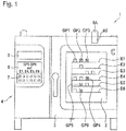
- a cooking device 1 according to the invention is shown, which has a cooking space 2 which is arranged in a housing or device housing 4.
- the cooking chamber 2 can be opened or closed via an openable and closable cooking chamber door 3.
- the cooking appliance 1 also has a control device 5, a display direction 6 and an input device 7.
- the cooking appliance 1 is provided with a sensor device 8B, which is shown in FIG Figure 1 is shown schematically simplified as a block.
- This sensor device 8B can, as in FIG Figure 1 shown, in the housing 4 or on the housing 4, for example on the front of the Housing 4 be arranged. It is also possible to provide the sensor device 8B in the cooking chamber door 3 or in the cooking chamber 2 itself.
- An example of such a sensor device is a camera, in particular in the form of a digital camera, for monitoring the cooking space 2 in order, for example, to monitor a cooking process of cooking products GP1 to GP6, which can be arranged on cooking product levels E1 to E6.
- the cooking appliance 1 according to the invention also has a cooling device 8A, which is also shown schematically in greatly simplified form by a block and which in the case of the FIG Figure 1
- the embodiment shown is arranged on the housing 4 by way of example.
- This cooling device 8A can, however, alternatively be arranged in the housing 4 and there in an area suitable for receiving the cooling device 8A, or it can also be provided in the cooking chamber door 3.
- This cooling device 8A serves to cool the sensor device 8B in order to ensure its function and efficiency.
- this cooling device 8A is illustrated below with reference to the detailed preparation in FIGS Figures 2 to 4 explained.
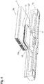
- the embodiments of the cooling device 8A according to FIG Figure 2 comprises a cooling housing 9, which can be constructed from a preferably highly thermally conductive material, such as aluminum.
- a cooling housing 9 is in an in Figure 2
- the sensor device 8B is arranged in the not visible receiving space, the lower part of which protruding from the cooling housing 9 in FIG Figure 2 is visible.
- the receiving space of the cooling housing 9 is closed with a cover 9A which is fixed on a housing body 9B.
- the cooling housing 9 is connected to a heat conduction bridge 10, which is also constructed from a thermally conductive, in particular highly thermally conductive material. These heat-conducting bridges 10 connect the cooling housing 9 to a carrier 11, which is also made of thermally conductive, preferably highly thermally conductive, material.
- These cooling elements 12A and 12B can be designed as Peltier elements, for example.
- the cooling device 8A has a heat dissipating element 13 which is arranged, for example, on the two cooling elements 12A and 12B.
- This heat dissipation element 13, as already explained at the beginning, is preferably arranged directly on the cooling elements 12A and 12B and, in a particularly preferred embodiment, it is possible to provide a layer of conductive paste, thermal film or heat conductive adhesive between the cooling elements 12A and 12B and the heat dissipation element 13, which however in Figure 2 is not visible, so this layer is based on the Figures 3 and 4th will be explained.
- the heat dissipating element 13 comprises two cooling fin blocks 13A and 13B, which are arranged on a carrier plate 13C and are arranged on the carrier plate 13C at a selectable distance A from one another.
- the cooling device 8A further comprises the embodiment according to FIG Figure 2 a fan or blower 17 which can direct a flow of cooling air K onto the cooling fin blocks 13A and 13B in order to be able to dissipate the heat extracted from the sensor device 8B.
- a mounting housing / outer housing 14 which has a central receiving area 14A for the cooling housing 9 and two adjacent mounting sections 14B and 14C with which the cooling device 8A of this embodiment is in or on the housing 4 or inside the oven door 3 can be fixed.
- This mounting housing 14 is made of a material such as plastic, which has poor thermal conductivity and is optionally equipped with further heat insulating elements so that the mounting housing 14 can prevent heat from entering the cooling housing 9, which occurs, for example, in a kitchen in which the cooking device according to the invention 1 is being operated, other devices or hot food vapors can arise.
- the in Figure 3 The construction of the assembly housing 14 shown is purely exemplary and can be adapted to the respective cooking appliance 1 with regard to its dimensions and shape so that the cooling device 8A can be arranged in or on the housing 4 or in the cooking chamber door 3.
- a layer 15 is also visible, which is the previously explained layer of conductive paste, thermal film or thermally conductive adhesive, but which is shown in FIG Figure 2 was not visible.
- FIG. 8 shows the bottom view of the embodiment according to FIG Figure 3 which makes it clear that it is possible to provide two such layers 15 and 16 made of conductive paste, thermal film or thermally conductive adhesive, the layer 16 being provided between the cooling elements 12A and 12B and the heat dissipating element 13. Furthermore, it is also possible here to provide a conductive paste, thermal film or a thermally conductive adhesive between the camera or sensor device 8B and the cooling housing 9.
- the embodiment of the cooling device 8A according to FIGS Figures 3 and 4th can of course also be used with a fan 17, as shown in Figure 2 is shown schematically simplified, can be combined. If a cooling air flow is available in cooking appliances that can be generated without such a fan 17, for example due to the design of the cooking appliance 1, it is not absolutely necessary for the cooling device 8A to interact with such a fan 17.
- Figure 5 corresponds to the representation of Figure 2 , so that reference can be made to the preceding description with regard to all matching features.
- FIG 5 is shown schematically simplified as an example that the inventive cooking device 1 and its cooling device 8A, in addition to the components already described above, can of course be provided with a controller 18 in every conceivable embodiment, which is in operative connection with a device control 19 via an operative connection line 25.
- the dashed lines 20 and 21 represent active connections between the controller 18 and the Peltier element (s) 12A or a sensor signal line to a temperature sensor 22, which is connected to the signal line 21 via a cable 23 and is arranged in the cooling housing 9.
- This temperature sensor 22 measures the internal temperature of the cooling housing 9 in order to monitor whether the sensor device 8B is operating in a tolerable temperature environment or whether the activation of the cooling is necessary in order to avoid overheating.
- the Peltier elements 12A, 12B can be controlled via the line 20 if such elements are provided as cooling elements.
- the connecting line 39 between the controller 18 and the fan 17 enables it to be switched on and off.
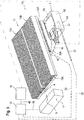
- FIG. 6 a further embodiment of the cooling device 8A according to the invention is shown. This corresponds essentially to the embodiment according to FIG Figure 2 , so that reference can be made to their description with regard to all matching features.
- light sources for example in the form of LEDs, can be provided which are shown in FIG Figure 6 are symbolized by the reference numerals 27 to 37.
- two height gauges 25 and 26 are also arranged, with which it is possible to determine the level at which food carriers are introduced into the cooking space.
- FIG Figure 6 characterized in that the fan or blower 17 interacts with a cooling duct 38.
- the fan 17 is arranged at the inlet of the cooling channel 38 and the heat dissipating element 13 is arranged in the cooling channel 38 away from the fan 17, as can be seen from the schematic diagram of FIG Figure 6 results.
- cooling strip 24 it is also possible, by providing the cooling strip 24, to dispense with one or more cooling elements, which is shown in FIG Figure 6 is symbolized by the fact that the reference number 12A is placed in brackets. Should it be necessary, a combination of one or more cooling elements 12A, 12B with the cooling strip 24 is of course also possible.
Landscapes
- Engineering & Computer Science (AREA)
- Microelectronics & Electronic Packaging (AREA)
- Physics & Mathematics (AREA)
- Food Science & Technology (AREA)
- Thermal Sciences (AREA)
- General Engineering & Computer Science (AREA)
- Mechanical Engineering (AREA)
- Chemical & Material Sciences (AREA)
- Combustion & Propulsion (AREA)
- Life Sciences & Earth Sciences (AREA)
- General Physics & Mathematics (AREA)
- Cooling Or The Like Of Electrical Apparatus (AREA)
- Electric Stoves And Ranges (AREA)
- Devices That Are Associated With Refrigeration Equipment (AREA)
- Electric Ovens (AREA)
Description
- Die Erfindung betrifft ein Gargerät, insbesondere in Form eines gewerblichen Gargeräts, gemäß dem Oberbegriff des Anspruchs 1. Ein derartiges Gargerät ist aus der
EP 2 639 514 A1 bekannt. - Ein weiteres Gargerät ist beispielsweise aus der
DE 10 2004 040 557 A1 bekannt. Diese Druckschrift beschreibt in der Ausführungsform gemäßFig. 3 die Anordnung eines elektronischen Bauelementes eines Gargerätes auf einem Kopf, der über einen Hals mit der Basis einer Kühleinrichtung verbunden ist, die eine Mehrzahl von Kühlrippen aufweist, die auf der Basis angeordnet sind. Bei der Ausführungsform gemäßFig. 3 ist diese Anordnung von einem Kanal umgeben, der jedoch nicht über den Kopf und den Hals mit der Basis wärmeleitend verbunden ist. - Ein weiteres Gargerät, das sowohl eine Kamera wie auch ein Kühlsystem aufweist, ist aus der
WO 2015/185211 bekannt. Weiterer relevanter Stand der Technik ist aus den DokumentenDE 10 2013 206868 A1 ,DE 10 2008 001675 A1 ,EP 2 775 790 A1 undDE 10 2009 031370 A1 bekannt. - Ausgehend von diesem Stand der Technik ist es Aufgabe der vorliegenden Erfindung, ein Gargerät der im Oberbegriff des Anspruchs 1 angegebenen Art zu schaffen, das eine hohe Kühlleistung ermöglicht und dabei einfach und kompakt aufgebaut ist.
- Die Lösung dieser Aufgabe erfolgt durch die Merkmale des Anspruches 1.
- Dementsprechend wird ein Gargerät, insbesondere in Form eines gewerblichen Gargeräts geschaffen. Hierbei wird im Rahmen dieser Anmeldung unter dem Begriff "Gargerät" sowohl gewerbliche Gargeräte wie auch Haushalts-Gargeräte und insgesamt ganz allgemein Nahrungsmittel-Behandlungs-Geräte verstanden, die sowohl eine kalte wie auch eine heiße Behandlung von Nahrungsmitteln durchführen können und beispielsweise Heißluftdämpfer, Kombi-Dämpfer, Getränke-Ausgabe-Automaten, Getränke-Mixer, Mikrowellen-Geräte und andere Nahrungsmittel-Behandlungs-Geräte umfassen können.
- Das erfindungsgemäße Gargerät weist ein Gehäuse auf, in dem ein Garraum angeordnet ist. Wie üblich kann dieser Garraum mithilfe einer öffnen- und schließbaren Garraumtür geöffnet und geschlossen werden.
- Ferner weist das erfindungsgemäße Gargerät eine Sensoreinrichtung auf, die insbesondere zum Auswählen, Führen und/oder Überwachen eines Garprogrammes zur Zubereitung von Gargütern im Garraum vorgesehen sein kann. Ein Beispiel für eine derartige Sensoreinrichtung ist eine Kamera, insbesondere in Form einer digitalen Kamera.
- Da sich eine derartige Sensoreinrichtung beim Betrieb erwärmt, was ihre Leistungsfähigkeit herabsetzen kann, weist das erfindungsgemäße Gargerät ferner eine Kühleinrichtung für die Sensoreinrichtung auf, mit der es möglich ist, die Sensoreinrichtung dauerhaft so zu kühlen, so dass sie in einem für eine optimale Leistung liegenden Temperaturbereich gehalten werden kann.
- Diese Kühleinrichtung kann ein Kühlgehäuse aufweisen, das aus wärmeleitfähigen, vorzugsweise hoch wärmeleitfähigen, Material aufgebaut ist. Das Kühlgehäuse kann hierbei einen Aufnahmeraum umfassen, in dem die Sensoreinrichtung angeordnet werden kann. Dieser Aufnahmeraum kann bei einer besonders bevorzugten Ausführungsform mittels eines abnehmbaren Deckels nach dem Einbringen der Sensoreinrichtung geschlossen werden.
- Ferner weist die Kühleinrichtung eine Wärmeleitbrücke auf, die ebenfalls aus wärmeleitfähigem Material, vorzugsweise hochwärmeleitfähigem Material aufgebaut ist. Diese Wärmeleitbrücke verbindet das Kühlgehäuse mit einem Träger, der ebenfalls aus wärmeleitfähigem und vorzugsweise aus hochwärmeleitfähigem Material aufgebaut ist. Dieser Träger kann beispielsweise eine Trägerplatte sein und vorzugsweise ein Kühlelement lagern. Hierbei ist es möglich, dass das Kühlelement entweder auf dem Träger bzw. der Trägerplatte oder im Träger angeordnet wird.
- Schließlich kann die Kühleinrichtung zumindest ein Wärmeableitelement aufweisen, das unmittelbar auf dem zumindest einen Kühlelement angeordnet ist, damit die durch das Kühlelement der Sensoreinrichtung entzogene Wärme abgeleitet werden kann.
- Die Sensoreinrichtung kann hierbei an einer geeigneten Stelle im oder am Gerätegehäuse angeordnet werden. Insbesondere ist es auch möglich, die Sensoreinrichtung im Garraum anzuordnen, wobei je nach Anordnung der Sensoreinrichtung an geeigneter Stelle im oder am Gerätegehäuse die Kühleinrichtung angeordnet werden kann, die ein kompaktes und leicht zu händelndes Bauteil darstellt, das je nach Gerätetyp hinsichtlich ihrer Komponenten entsprechend baulich angepasst werden kann, damit ein Einbau im oder am Gerätegehäuse problemlos möglich ist.
- Der Aufbau des erfindungsgemäßen Gargerätes macht es möglich, die Sensoreinrichtung (Kamera) von der Kühleinrichtung zu entkoppeln, insbesondere sie örtlich voneinander zu trennen, da der Sensor (Kamera) an einer Stelle am Gargerät montiert ist, an der die Kühleinrichtung nicht untergebracht werden könnte.
- Aus der
DE 10 2008 001 675 A1 ist zwar ein Kameramodul bekannt, das einen Bildsensorchip und mindestens ein Peltierelement mit einer kühlenden Oberfläche aufweist. Der Bildsensorchip ist mit der kühlenden Oberfläche des Peltierelementes durch mindestens ein Wärmesammelelement verbunden, wohingegen ein Gehäuse, das den Bildsensorchip umgibt, nicht in wärmeleitender Verbindung mit dem Peltierelement steht. - Schließlich ist aus der
DE 103 19 176 A1 zwar eine Vorrichtung zur Kühlung einer Kamera bekannt, die einen Bildsensor und eine Verarbeitungseinheit aufweist. Diese Elemente sind thermisch mit einem Ende einer Einrichtung zur Wärmeleitung verbunden, die ihrerseits wärmeleitend mit einem Kühlkörper in Verbindung steht. Das den Bildsensor und die Verarbeitungseinheit umgebende Gehäuse ist auch bei dieser Anordnung nicht wärmeleitend mit dem Kühlkörper gekoppelt. - Die Unteransprüche haben vorteilhafte Weiterbildungen zum Inhalt.
- Um einen kompakten und anpassungsfähigen Aufbau der erfindungsgemäßen Kühleinrichtung möglich zu machen, können deren Komponente einstückig miteinander verbunden sein oder es ist alternativ ebenfalls möglich, die Komponenten als separate Bauteile auszubilden, die auf geeignete Art und Weise miteinander verbunden werden können. Als Verbindungstechniken sind Schweißungen, Lötungen oder auch Verklebungen denkbar.
- Ferner ist es erfindungsgemäß, dass das Kühlgehäuse in einem Montagegehäuse anzuordnen, das aus einem schlecht wärmeleitfähigen Material, wie beispielsweise Kunststoff, aufgebaut sein kann, um das Kühlgehäuse vor einer Erwärmung durch Wärmeströme von außen zu schützen, die beispielsweise im Küchenbetrieb von anderen wärmeproduzierenden Geräten erzeugt werden können. Ferner ist es möglich, sämtliche temperaturempfindliche Komponenten des erfindungsgemäßen Gargerätes durch zusätzliche Isolierungselemente gegen einen Wärmeeintrag von außen, beispielsweise durch das erwärmte Klima der Küche oder durch weitere in der Küche befindliche Geräte, zu schützen.
- Bei einer besonders bevorzugten Ausführungsform ist es möglich, mehr als ein Kühlelement, insbesondere zwei Kühlelemente vorzusehen, die ebenfalls zur Anpassung von baulichen Gegebenheiten üblicherweise beabstandet zueinander angeordnet werden können. Vom Prinzip her ist es natürlich möglich, auch eine größere Anzahl als zwei derartiger Kühlelemente vorzusehen, die in Dimension und Anordnung an die baulichen Gegebenheiten des jeweiligen Gargeräts angepasst werden können.
- Um die Wärmeleitung noch weiter zu verbessern, ist es bei einer weiteren bevorzugten Ausführungsform möglich, zwischen dem oder den Kühlelementen und dem Träger eine Schicht aus Leitpaste, Thermofolie oder auch aus einem Wärmeleitkleber vorzusehen, damit die Kühlleistung der erfindungsgemäßen Kühleinrichtung weiter verbessert werden kann.
- Eine derartige Schicht aus einer Leitpaste, einer Thermofolie und/oder einem Wärmeleitkleber kann ferner zwischen dem bzw. den Kühlelementen und dem Wärmeableitelement vorgesehen sein.
- Bei einer weiteren besonders bevorzugten Ausführungsform weist die erfindungsgemäße Kühleinrichtung ferner einen Lüfter, beispielsweise in Form eines Lüftergebläses, auf, der auf das Wärmeableitelement gerichtet ist, damit der vom Lüfter erzeugte Luftstrom auf das Wärmeableitelement geleitet werden kann, damit dieser Kühlluftstrom die Wärme, die sich im Wärmeableitelement gesammelt hat, mit hoher Effizienz ableiten kann.
- Bei einer weiteren besonders bevorzugten Ausführungsform ist es möglich, den Lüfter mit einem Kühlkanal zu kombinieren, in dem das Wärmeableitelement angeordnet werden kann. In diesem Falle wird der Kühler unmittelbar an den Kühlkanal angeschlossen und saugt Kaltluft ab und kann diese Kaltluft durch die Leitfunktion des Kühlkanals noch gezielter auf das Kühlelement, insbesondere auf Kühlrippen dieses Kühlelements, leiten. Nach dem Durchlauf durch das Kühlelement, bei dem sich die Kaltluft erwärmt hat, kann diese über einen Endbereich des Kühlkanals an einer geeigneten Stelle abgeleitet werden kann, was eine weitere Effizienzerhöhung der Kühlung ergibt.
- Das Wärmeableitelement kann beispielsweise eine Mehrzahl von Kühlrippen aufweisen, die bei einer besonders bevorzugten Ausführungsform in zwei Kühlrippenblocks unterteilt sein können und beispielsweise auf einer Trägerplatte angeordnet sein können.
- Je nach Gerätetyp ist es ferner möglich, das Wärmeableitelement symmetrisch oder insbesondere auch asymmetrisch bezüglich des bzw. der Kühlelemente anzuordnen, um je nach den baulichen und funktionellen Bedingungen des erfindungsgemäßen Gargeräts eine hocheffiziente Kühleinrichtung mit hoher Kühlleistung erreichen zu können.
- Ein besonders bevorzugtes Material für alle Komponenten der erfindungsgemäßen Kühleinrichtung mit hoher Wärmeleitfähigkeit ist Aluminium.
- Die Kühlelemente sind bevorzugterweise als Peltier-Elemente (TEC) ausgebildet. Alternativ ist es auch möglich, das bzw. die Kühlelemente als Wärmetauscher auszubilden.
- Eine weitere Alternative für Kühlelemente könnte beispielsweise ein Wasserkühler sein.
- In den Ansprüchen 16 und 17 ist die erfindungsgemäße Kühleinrichtung als selbstständig handelbares Objekt definiert.
- Bei allen zuvor beschriebenen Ausführungsbeispielen des erfindungsgemäßen Gargeräts und der erfindungsgemäßen Kühleinrichtung sind natürlich sämtliche erforderlichen Regler, Gerätesteuerungen und Wirkverbindungen, Signalleitungen, Anschlusskabel und, falls erforderlich, Energiequellen zur Stromversorgung vorgesehen und können in der jeweils erforderlichen Kombination implementiert werden.
- Weitere Einzelheiten, Vorteile und Merkmale der vorliegenden Erfindung ergeben sich aus nachfolgender Beschreibung von Ausführungsbeispielen anhand der Zeichnung. Darin zeigt:
- Figur 1
- eine schematisch stark vereinfachte Prinzipdarstellung einer Ausführungsform eines erfindungsgemäßen Gargeräts,
- Figur 2
- eine perspektivische Darstellung einer ersten Ausführungsform der erfindungsgemäßen Kühleinrichtung,
- Figur 3
- eine perspektivische Darstellung einer zweiten Ausführungsform der erfindungsgemäßen Kühleinrichtung,
- Figur 4
- eine perspektivische Unteransicht der Ausführungsform der Kühleinrichtung gemäß
Figur 3 , - Fig. 5
- eine der
Figur 2 entsprechende Darstellung der ersten Ausführungsform der erfindungsgemäßen Kühleinrichtung, die zur Erläuterung des Vorsehens eines Reglers und einer Gerätesteuerung sowie eines Temperaturfühlers mit entsprechenden Wirk- und Signalleitungen ergänzt ist, und - Fig. 6
- eine weitere Ausführungsform der erfindungsgemäßen Kühleinrichtung.
- In
Figur 1 ist ein erfindungsgemäßes Gargerät 1 dargestellt, das einen Garraum 2 aufweist, der in einem Gehäuse bzw. Gerätegehäuse 4 angeordnet ist. Der Garraum 2 kann über eine öffnen- und schließbare Garraumtür 3 geöffnet bzw. geschlossen werden. - Das Gargerät 1 weist ferner eine Steuereinrichtung 5, eine Anzeigerichtung 6 sowie eine Eingabeeinrichtung 7 auf.
- Schließlich ist das Gargerät 1 mit einer Sensoreinrichtung 8B versehen, die in
Figur 1 schematisch vereinfacht als Block dargestellt ist. Diese Sensoreinrichtung 8B kann, wie inFigur 1 dargestellt, im Gehäuse 4 oder am Gehäuse 4, beispielsweise an der Frontseite des Gehäuses 4 angeordnet sein. Ferner ist es möglich, die Sensoreinrichtung 8B in der Garraumtür 3 vorzusehen oder im Garraum 2 selber. Ein Beispiel für eine derartige Sensoreinrichtung ist eine Kamera, insbesondere in Form einer Digitalkamera zur Überwachung des Garraums 2, um beispielsweise einen Garvorgang von Garprodukten GP1 bis GP 6 zu überwachen, die auf Gargutebenen E1 bis E6 angeordnet sein können. - Das erfindungsgemäße Gargerät 1 weist ferner eine ebenfalls durch einen Block schematisch stark vereinfacht dargestellte Kühleinrichtung 8A auf, die bei der in
Figur 1 dargestellten Ausführungsform beispielhaft auf dem Gehäuse 4 angeordnet ist. Diese Kühleinrichtung 8A kann jedoch alternativ im Gehäuse 4, und dort in einem für die Aufnahme der Kühleirichtung 8A geeigneten Bereich angeordnet werden oder ebenfalls in der Garraumtür 3 vorgesehen sein. Diese Kühleinrichtung 8A dient zur Kühlung der Sensoreinrichtung 8B, um deren Funktion und Effizienz sicherzustellen. - Der Aufbau dieser Kühleinrichtung 8A wird nachfolgend anhand der Detailerstellung in den
Figuren 2 bis 4 erläutert. - Die Ausführungsformen der Kühleinrichtung 8A gemäß
Figur 2 umfasst ein Kühlgehäuse 9, das aus einem vorzugsweise hochwärmeleitfähigen Material, wie beispielsweise Aluminium, aufgebaut sein kann. Im Kühlgehäuse 9 ist in einem inFigur 2 nicht sichtbaren Aufnahmeraum die Sensoreinrichtung 8B angeordnet, deren unterer aus dem Kühlgehäuse 9 vorragende Teil inFigur 2 sichtbar ist. Der Aufnahmeraum des Kühlgehäuses 9 ist mit einem Deckel 9A verschlossen, der auf einen Gehäusekörper 9B fixiert ist. - Das Kühlgehäuse 9 ist mit einer Wärmeleitbrücke 10 verbunden, die ebenfalls aus einem wärmeleitfähigen, insbesondere hochwärmeleitfähigen Material aufgebaut ist. Diese Wärmeleitbrücken 10 verbindet das Kühlgehäuse 9 mit einem Träger 11, der ebenfalls aus wärmeleitfähigem, vorzugsweise hochwärmeleitfähigem, Material ausgebildet ist. Der Träger 11, der bei der dargestellten Ausführungsform als Trägerplatte ausgebildet ist, lagert zumindest ein Kühlelement, im dargestellten beispielsweise jedoch zwei Kühlelemente 12A und 12B. Diese Kühlelemente 12A und 12B können beispielsweise als Peltier-Elemente ausgebildet sein.
- Schließlich weist die Kühleinrichtung 8A ein Wärmeableitelement 13 auf, das im beispielsweise auf den beiden Kühlelementen 12A und 12B angeordnet ist. Vorzugsweise ist dieses Wärmeableitelement 13, wie eingangs bereits erläutert, unmittelbar auf den Kühlelementen 12A und 12B angeordnet und es ist bei einer besonders bevorzugten Ausführungsform möglich, eine Schicht aus Leitpaste, Thermofolie oder Wärmeleitkleber zwischen den Kühlelementen 12A und 12B und dem Wärmeableitelement 13 vorzusehen, die jedoch in
Figur 2 nicht sichtbar ist, sodass diese Schicht anhand derFiguren 3 und4 erläutert werden wird. - Wie
Figur 2 ferner verdeutlicht, umfasst bei dieser Ausführungsform das Wärmeableitelement 13 zwei Kühlrippenblöcke 13A und 13B, die auf einer Trägerplatte 13C angeordnet sind und um einen wählbaren Abstand A beabstandet zueinander auf der Trägerplatte 13C angeordnet sind. - Ferner umfasst die Kühleinrichtung 8A der Ausführungsform gemäß
Figur 2 einen Lüfter bzw. ein Gebläse 17, das einen Kühlluftstrom K auf die Kühlrippenblöcke 13A und 13B leiten kann, um die der Sensoreinrichtung 8B entzogene Wärme ableiten zu können. - Bei der Ausführungsform gemäß
Figur 3 ist zusätzlich zu den zuvor genannten Komponenten der Kühleinrichtung 8A ein Montagegehäuse/Außengehäuse 14 vorgesehen, das einen mittigen Aufnahmebereich 14A für das Kühlgehäuse 9 und zwei daran angrenzende Montageabschnitte 14B und 14C aufweist, mit denen die Kühleinrichtung 8A dieser Ausführungsform im oder am Gehäuse 4 oder innerhalb der Garraumtür 3 fixiert werden kann. Dieses Montagegehäuse 14 ist aus einem Material, wie beispielsweise Kunststoff, aufgebaut, der schlecht wärmeleitfähig ist und gegebenenfalls mit weiteren Wärmeisolierelementen ausgestattet ist, damit das Montagegehäuse 14 einen Wärmeeintrag in das Kühlgehäuse 9 verhindern kann, der beispielsweise in einer Küche, in der das erfindungsgemäße Gargerät 1 betrieben wird, durch andere Geräte oder heiße Gargutdämpfe entstehen kann. Der inFigur 3 dargestellte Aufbau des Montagegehäuses 14 ist rein beispielhaft und kann an das jeweilige Gargerät 1 hinsichtlich seiner Dimensionierung und Formgebung angepasst werden, damit die Kühleinrichtung 8A im oder am Gehäuse 4 oder in der Garraumtür 3 angeordnet werden kann. - In
Figur 3 ist ferner eine Schicht 15 sichtbar, die die zuvor erläuterte Schicht aus Leitpaste, Thermofolie oder Wärmeleitkleber ist, die jedoch inFigur 2 nicht sichtbar war. -
Figur 4 stellt die Unteransicht der Ausführungsform gemäßFigur 3 dar, die verdeutlicht, dass es möglich ist, zwei derartige Schichten 15 und 16 aus Leitpaste, Thermofolie oder Wärmeleitkleber vorzusehen, wobei die Schicht 16 zwischen den Kühlelementen 12A und 12B und dem Wärmeableitelement 13 vorgesehen ist. Ferner ist es auch hier möglich, eine Leitpaste, Thermofolie oder einen Wärmeleitkleber zwischen der Kamera bzw. Sensoreinrichtung 8B und dem Kühlgehäuse 9 vorzusehen. - Die Ausführungsform der Kühleinrichtung 8A gemäß den
Figuren 3 und4 kann natürlich ebenfalls mit einem Lüfter 17, wie er inFigur 2 schematisch vereinfacht dargestellt ist, kombiniert werden. Falls bei Gargeräten ein Kühlluftstrom zur Verfügung steht, der ohne einen derartigen Lüfter 17, beispielsweise aufgrund der Bauart des Gargerätes 1 erzeugbar ist, ist es nicht zwingend nötig, dass die Kühleinrichtung 8A mit einem derartigen Lüfter 17 zusammenwirkt. -
Figur 5 entspricht der Darstellung derFigur 2 , so dass hinsichtlich aller übereinstimmenden Merkmale auf die vorangehende Beschreibung verwiesen werden kann. - In
Figur 5 ist beispielhaft schematisch vereinfacht dargestellt, dass das erfindungsgemäße Gargerät 1 und dessen Kühleinrichtung 8A neben den zuvor bereits beschriebenen Komponenten natürlich bei jeder denkbaren Ausführungsform mit einem Regler 18 versehen sein kann, der mit einer Gerätesteuerung 19 über eine Wirkverbindungsleitung 25 in Wirkverbindung steht. - Die gestrichelten Linien 20 und 21 stellen Wirkverbindungen zwischen dem Regler 18 und dem bzw. den Peltier-Elementen 12A bzw. eine Fühlersignalleitung zu einem Temperaturfühler 22 dar, der über ein Kabel 23 mit der Signalleitung 21 verbunden ist und im Kühlgehäuse 9 angeordnet ist. Dieser Temperaturfühler 22 misst die Innentemperatur des Kühlgehäuses 9, um zu überwachen, ob die Sensoreinrichtung 8B in einem tolerablen Temperaturumfeld arbeitet oder ob die Aktivierung der Kühlung erforderlich ist, um eine Überhitzung zu vermeiden.
- Über die Leitung 20 können die Peltier-Elemente 12A, 12B, falls als Kühlelemente derartige Elemente vorgesehen sind, angesteuert werden.
- Die Verbindungsleitung 39 zwischen dem Regler 18 und dem Lüfter 17 ermöglicht es, diesen ein- bzw. auszuschalten.
- In
Figur 6 ist eine weitere Ausführungsform der erfindungsgemäßen Kühleinrichtung 8A dargestellt. Diese entspricht im Wesentlichen der Ausführungsform gemäßFigur 2 , so dass hinsichtlich aller übereinstimmenden Merkmale auf deren Beschreibung Bezug genommen werden kann. - Als weiteres Merkmal ist bei dieser Ausführungsform jedoch eine Kühlleiste 24, beispielsweise aus Aluminium, vorgesehen, die mit dem Kühlgehäuse 9 verbunden ist. An der Unterseite dieser Kühlleiste 24 können Lichtquellen, beispielsweise in Form von LEDs, vorgesehen sein, die in
Figur 6 durch die Bezugszeichen 27 bis 37 symbolisiert sind. - An den beiden Endbereichen der Kühlleiste 24 sind ferner zwei Höhenmesser 25 und 26 angeordnet, mit denen es möglich ist, zu bestimmen, auf welcher Ebene Gargutträger in den Garraum eingebracht werden. Diese Höhenmesser stehen natürlich mit dem zuvor anhand
Figur 5 erläuterten Regler 18 und der Gerätesteuerung 19 in Wirkverbindung, wobei die Lichtquellen über den Regler ein- und ausgeschaltet werden können. - Ferner ist es bei dieser Ausführungsform möglich, vom Kühlgehäuse 9 aus jeweils in Richtung der beiden Höhenmesser 25 bzw. 26 verschiedene Temperaturzonen über die Geometrie der Kühlleiste 24 einzustellen, da in dieser Richtung, also vom Kühlgehäuse 9 zu den beiden Höhensensoren 25 bzw. 26, die Temperatur zunimmt.
- Ferner zeichnet sich die Ausführungsform der
Figur 6 dadurch aus, dass der Lüfter bzw. das Gebläse 17 mit einem Kühlkanal 38 zusammenwirkt. Bei der dargestellten Ausführungsform ist das Gebläse 17 am Eingang des Kühlkanals 38 angeordnet und das Wärmeableitelement 13 ist, entfernt vom Gebläse 17 im Kühlkanal 38 angeordnet, wie sich dies aus der Prinzipdarstellung derFigur 6 ergibt. - Somit ist es bei dieser Ausführungsform möglich, über das Gebläse 17 Frischluft anzusaugen und diese im Kühlkanal 38 über das Wärmeableitelement 13 zu leiten und am gegenüberliegenden Ende die erwärmte Luft in einem geeigneten Bereich im oder außerhalb des erfindungsgemäßen Gargerätes 1 abzuführen. Dies erhöht weiter die Effizienz der Kühlleistung der erfindungsgemäßen Kühleinrichtung 8A.
- Bei dieser Ausführungsform ist es ferner möglich, durch das Vorsehen der Kühlleiste 24 auf ein oder mehrere Kühlelemente zu verzichten, was in
Figur 6 dadurch symbolisiert ist, dass die Bezugsziffer 12A in Klammern gesetzt ist. Sollte es erforderlich sein, ist natürlich auch eine Kombination von einem oder mehreren Kühlelementen 12A, 12B mit der Kühlleiste 24 möglich. - Neben der voranstehenden schriftlichen Offenbarung wird hiermit zur Ergänzung der Offenbarung explizit auf die Darstellung der Erfindung in den
Figuren 1 bis 6 Bezug genommen. -
- 1
- Gargerät
- 2
- Garraum
- 3
- Garraumtür
- 4
- Gehäuse/Gerätegehäuse
- 5
- Steuereinrichtung
- 6
- Anzeigeeinrichtung/Display
- 7
- Eingabeeinrichtung/Tastatur
- 8A
- Kühleinrichtung
- 8B
- Sensoreinrichtung
- E1 bis E6
- Gargutebenen
- GP1 bis GP6
- Garprodukte
- 9
- Kühlgehäuse
- 9A
- Deckel
- 9B
- Gehäusekörper
- 10
- Wärmeleitbrücke
- 11
- Träger/Trägerplatte
- 12A, 12B
- Kühlelement
- 13
- Wärmeableitelement
- 13A, 13B
- Kühlrippenblöcke
- 14
- Montagegehäuse/Außengehäuse
- 14A
- Aufnahmebereich
- 14B, 14C
- Montagebereich
- 15, 16
- Schichten
- 17
- Lüfter/Gebläse
- 18
- Regler
- 19
- Gerätesteuerung
- 20, 21
- Wirkverbindung/Signalverbindung
- 22
- Temperaturfühler
- 23
- Kabel
- 24
- Kühlleiste
- 25,26
- Höhensensor
- 27-37
- Lichtquellen/LEDs
- 38
- Kühlkanal
- 39, 40
- Wirkverbindung/Signalverbindung
- K
- Kühlluftstrom
- A
- Abstand zwischen den Kühlrippenblöcken 13A und 13B
Claims (14)
- Gargerät (1), insbesondere gewerbliches Gargerät- mit einem Gehäuse (4), in dem ein Garraum (2) angeordnet ist;- mit zumindest einer Sensoreinrichtung (8B); und- mit einer Kühleinrichtung (8A) für die Sensoreinrichtung (8B), die folgende Komponenten umfasst:- ein Kühlgehäuse (9), in dem die Sensoreinrichtung (8B) angeordnet ist,- eine Wärmeleitbrücke (10), und- zumindestens ein Wärmeableitelement (13), das auf einem Träger (11) angeordnet ist,- wobei das Kühlgehäuse (9) aus wärmeleitfähigem, vorzugsweise hochwärmeleitfähigem Material, besteht, und- wobei die Wärmeleitbrücke (10) aus wärmeleitfähigem, vorzugsweise hochwärmeleitfähigem, Material das Kühlgehäuse (9) mit dem Träger (11) aus wärmeleitfähigem, vorzugsweise hochwärmeleitfähigem Material verbindet,dadurch gekennzeichnet, dass der Träger (11) zumindest ein Kühlelement (12A, 12B) lagert, wobei das zumindest eine Wärmeableitelement (13) auf dem zumindest einen Kühlelement (12A, 12B) angeordnet ist,
und dadurch gekennzeichnet, dass das Kühlgehäuse (9) in einem Montagegehäuse (14) aus schlecht wärmeleitfähigem Material, insbesondere Kunststoff, angeordnet ist. - Gargerät nach Anspruch 1, dadurch gekennzeichnet, dass das Kühlgehäuse (9), die Wärmeleitbrücke (10) und der Träger (11) einstückig ausgebildet sind oder dass das Kühlgehäuse (9), die Wärmeleitbrücke (10) und der Träger (11) separate Komponenten sind, die miteinander verbunden, insbesondere verschweißt, verklebt oder verlötet, sind.
- Gargerät nach einem der Ansprüche 1 oder 2, dadurch gekennzeichnet, dass im oder um das Kühlgehäuse (9) herum zusätzlich Wärmeisolierelemente vorgesehen sind.
- Gargerät nach einem der Ansprüche 1 bis 3, dadurch gekennzeichnet, dass zwei Kühlelemente (12A, 12B) vorgesehen sind, die vorzugsweise beabstandet zueinander angeordnet sind oder die unmittelbar nebeneinander angeordnet sind.
- Gargerät nach einem der Ansprüche 1 bis 4, dadurch gekennzeichnet, dass zwischen dem zumindest einen Kühlelement (12A, 12B) und dem Träger (11) eine Schicht (15) aus Leitpaste, Thermofolie oder Wärmeleitkleber vorgesehen ist.
- Gargerät nach einem der Ansprüche 1 bis 5, dadurch gekennzeichnet, dass zwischen dem zumindest einen Kühlelement (12A, 12B) und dem Wärmeableitelement (13) eine Schicht (16) aus Leitpaste, Thermofolie oder Wärmeleitkleber vorgesehen ist.
- Gargerät nach einem der Ansprüche 1 bis 6, dadurch gekennzeichnet, dass die Kühleinrichtung (8A) einen Lüfter (17) aufweist, der auf das Wärmeableitelement (13) gerichtet ist, der vorzugsweise an einem Luftleitkanal bzw. Kühlkanal (38) angeordnet ist, in dem das Wärmeableitelement (13) platzierbar ist.
- Gargerät nach einem der Ansprüche 1 bis 7, dadurch gekennzeichnet, dass das wärmeleitfähige Material Aluminium ist.
- Gargerät nach einem der Ansprüche 1 bis 8, dadurch gekennzeichnet, dass das Wärmeableitelement (13) eine Mehrzahl von Kühlrippen aufweist.
- Gargerät nach Anspruch 9, dadurch gekennzeichnet, dass die Kühlrippen in zwei Kühlrippenblocks (13A, 13B) aufgeteilt sind.
- Gargerät nach Anspruch 9 oder 10, dadurch gekennzeichnet, dass die Kühlrippen auf einer Trägerplatte (13C) angeordnet sind.
- Gargerät nach einem der Ansprüche 1 bis 11, dadurch gekennzeichnet, dass das Wärmeableitelement (13) symmetrisch oder asymmetrisch bezüglich des zumindest einen Kühlelements (12A, 12B) angeordnet ist.
- Gargerät nach einem der Ansprüche 1 bis 12, dadurch gekennzeichnet, dass das zumindest eine Kühlelement (12A, 12B) als Peltier-Element ausgebildet ist.
- Gargerät nach einem der Ansprüche 1 bis 12, dadurch gekennzeichnet, dass das zumindest eine Kühlelement (12A, 12B) als Wärmetauscher ausgebildet ist.
Applications Claiming Priority (1)
| Application Number | Priority Date | Filing Date | Title |
|---|---|---|---|
| DE102018215434.1A DE102018215434A1 (de) | 2018-09-11 | 2018-09-11 | Gargerät |
Publications (2)
| Publication Number | Publication Date |
|---|---|
| EP3623705A1 EP3623705A1 (de) | 2020-03-18 |
| EP3623705B1 true EP3623705B1 (de) | 2021-12-01 |
Family
ID=67902384
Family Applications (1)
| Application Number | Title | Priority Date | Filing Date |
|---|---|---|---|
| EP19196184.6A Active EP3623705B1 (de) | 2018-09-11 | 2019-09-09 | Gargerät |
Country Status (3)
| Country | Link |
|---|---|
| US (1) | US11913649B2 (de) |
| EP (1) | EP3623705B1 (de) |
| DE (1) | DE102018215434A1 (de) |
Families Citing this family (2)
| Publication number | Priority date | Publication date | Assignee | Title |
|---|---|---|---|---|
| WO2020102916A1 (en) * | 2018-11-22 | 2020-05-28 | V-Zug Ag | Household oven with led illumination. |
| CN113827100B (zh) * | 2021-11-05 | 2022-08-02 | 广东美芝制冷设备有限公司 | 烹饪器具及控制方法、控制装置和计算机可读存储介质 |
Family Cites Families (13)
| Publication number | Priority date | Publication date | Assignee | Title |
|---|---|---|---|---|
| JP2004221103A (ja) * | 2003-01-09 | 2004-08-05 | Matsushita Electric Ind Co Ltd | 電子部品の冷却装置 |
| DE10319176A1 (de) * | 2003-04-29 | 2004-11-18 | Robert Bosch Gmbh | Vorrichtung zur Kühlung einer Kamera |
| DE102004040557A1 (de) * | 2004-08-16 | 2006-02-23 | Kern, Dietmar, Dr.-Ing. | Elektronikkühlkörper |
| CN100570865C (zh) * | 2007-02-28 | 2009-12-16 | 长春藤控股有限公司 | 散热装置 |
| JP5023996B2 (ja) * | 2007-11-26 | 2012-09-12 | 日本軽金属株式会社 | 電子機器収納箱および電子機器試験箱 |
| DE102008001675A1 (de) * | 2008-05-09 | 2009-11-12 | Robert Bosch Gmbh | Kameramodul mit verbessertem Kühlkonzept |
| JP4712913B2 (ja) * | 2008-08-08 | 2011-06-29 | 三菱電機株式会社 | 加熱調理器 |
| DE102009031370A1 (de) * | 2009-07-01 | 2011-01-05 | Siemens Aktiengesellschaft | Kühleinrichtung |
| EP2639514B1 (de) * | 2012-03-14 | 2021-05-12 | BSH Hausgeräte GmbH | Gargerätevorrichtung |
| DE102013102116A1 (de) * | 2013-03-04 | 2014-09-18 | Miele & Cie. Kg | Kocheinrichtung |
| DE102013206868A1 (de) * | 2013-04-16 | 2014-05-08 | E.G.O. Elektro-Gerätebau GmbH | Verfahren zur Kühlung eines Halbleiterbauteils und Vorrichtung |
| CA3199520A1 (en) * | 2014-06-05 | 2015-12-10 | Ingo Stork Genannt Wersborg | Heat treatment monitoring system |
| JP7221689B2 (ja) * | 2015-09-10 | 2023-02-14 | ブラバ・ホーム・インコーポレイテッド | オーブン内カメラ |
-
2018
- 2018-09-11 DE DE102018215434.1A patent/DE102018215434A1/de not_active Withdrawn
-
2019
- 2019-09-09 EP EP19196184.6A patent/EP3623705B1/de active Active
- 2019-09-10 US US16/566,192 patent/US11913649B2/en active Active
Non-Patent Citations (1)
| Title |
|---|
| None * |
Also Published As
| Publication number | Publication date |
|---|---|
| US11913649B2 (en) | 2024-02-27 |
| EP3623705A1 (de) | 2020-03-18 |
| DE102018215434A1 (de) | 2020-03-12 |
| US20200080783A1 (en) | 2020-03-12 |
Similar Documents
| Publication | Publication Date | Title |
|---|---|---|
| EP2126990B1 (de) | Fahrzeug mit einem thermoelektrischen generator | |
| EP0632231B1 (de) | Vorrichtung mit einer Bedienungs- und Anzeigeeinheit und einer Kochfeldplatte | |
| EP3016558B1 (de) | Temperierschrank | |
| DE102017213582B4 (de) | Lüftervorrichtung für ein Elektrogerät, Elektrogerät und Verfahren zur Steuerung derselben | |
| DE102011107078B4 (de) | Heizkreis und Elektronikanordnung | |
| EP1866728B1 (de) | Kühleinheit | |
| DE19935835C5 (de) | Induktionskochfeld mit Kühlgebläse | |
| EP3623705A1 (de) | Gargerät | |
| DE102020121633A1 (de) | Induktionskochfeld | |
| DE112007002332B4 (de) | Heizvorrichtungsanordnung | |
| DE112011101959T5 (de) | Wärmesenke und Verfahren zu deren Herstellung | |
| EP2600978B1 (de) | Zentrifuge mit kompressorkühlung | |
| EP2991466B1 (de) | Temperiereinrichtung zum regulieren der temperatur in einem raum und schaltschrank mit einer derartigen temperiereinrichtung | |
| DE19744422B4 (de) | Elektromotor mit variabler Drehzahl | |
| DE102005016115B4 (de) | Anordnung zum Kühlen eines elektronischen Gerätes | |
| DE10321022B4 (de) | Tablettenpresse | |
| EP0003764B1 (de) | Doppelbackofen, insbesondere Einbaubackofen | |
| DE102007017624B4 (de) | Thermoelektrische Temperiervorrichtung | |
| DE102006005293A1 (de) | Backofen | |
| EP3818922B1 (de) | Kühlvorrichtung für ein endoskop oder exoskop | |
| EP2444738B1 (de) | Gargerät mit einem Backofen | |
| EP3367769B1 (de) | Vorrichtung zur aufnahme einer elektronik | |
| DE102013207787A1 (de) | Kochfeldvorrichtung | |
| DE102014217639B4 (de) | Gargerät mit einer Gehäuseaußenwand, die nach innen hin spezifisch geprägt ist sowie Anordnung mit einem Gargerät | |
| EP2570881B2 (de) | Temperaturregelvorrichtung, insbesondere Thermostatvorrichtung |
Legal Events
| Date | Code | Title | Description |
|---|---|---|---|
| PUAI | Public reference made under article 153(3) epc to a published international application that has entered the european phase |
Free format text: ORIGINAL CODE: 0009012 |
|
| STAA | Information on the status of an ep patent application or granted ep patent |
Free format text: STATUS: THE APPLICATION HAS BEEN PUBLISHED |
|
| AK | Designated contracting states |
Kind code of ref document: A1 Designated state(s): AL AT BE BG CH CY CZ DE DK EE ES FI FR GB GR HR HU IE IS IT LI LT LU LV MC MK MT NL NO PL PT RO RS SE SI SK SM TR |
|
| AX | Request for extension of the european patent |
Extension state: BA ME |
|
| STAA | Information on the status of an ep patent application or granted ep patent |
Free format text: STATUS: REQUEST FOR EXAMINATION WAS MADE |
|
| 17P | Request for examination filed |
Effective date: 20200827 |
|
| RBV | Designated contracting states (corrected) |
Designated state(s): AL AT BE BG CH CY CZ DE DK EE ES FI FR GB GR HR HU IE IS IT LI LT LU LV MC MK MT NL NO PL PT RO RS SE SI SK SM TR |
|
| STAA | Information on the status of an ep patent application or granted ep patent |
Free format text: STATUS: EXAMINATION IS IN PROGRESS |
|
| 17Q | First examination report despatched |
Effective date: 20201102 |
|
| RIC1 | Information provided on ipc code assigned before grant |
Ipc: F24C 7/08 20060101AFI20210610BHEP Ipc: A21B 3/00 20060101ALI20210610BHEP Ipc: F24C 15/00 20060101ALI20210610BHEP |
|
| GRAP | Despatch of communication of intention to grant a patent |
Free format text: ORIGINAL CODE: EPIDOSNIGR1 |
|
| STAA | Information on the status of an ep patent application or granted ep patent |
Free format text: STATUS: GRANT OF PATENT IS INTENDED |
|
| INTG | Intention to grant announced |
Effective date: 20210728 |
|
| RAP1 | Party data changed (applicant data changed or rights of an application transferred) |
Owner name: WELBILT DEUTSCHLAND GMBH |
|
| GRAS | Grant fee paid |
Free format text: ORIGINAL CODE: EPIDOSNIGR3 |
|
| GRAA | (expected) grant |
Free format text: ORIGINAL CODE: 0009210 |
|
| STAA | Information on the status of an ep patent application or granted ep patent |
Free format text: STATUS: THE PATENT HAS BEEN GRANTED |
|
| AK | Designated contracting states |
Kind code of ref document: B1 Designated state(s): AL AT BE BG CH CY CZ DE DK EE ES FI FR GB GR HR HU IE IS IT LI LT LU LV MC MK MT NL NO PL PT RO RS SE SI SK SM TR |
|
| REG | Reference to a national code |
Ref country code: GB Ref legal event code: FG4D Free format text: NOT ENGLISH |
|
| REG | Reference to a national code |
Ref country code: AT Ref legal event code: REF Ref document number: 1452110 Country of ref document: AT Kind code of ref document: T Effective date: 20211215 Ref country code: CH Ref legal event code: EP |
|
| REG | Reference to a national code |
Ref country code: IE Ref legal event code: FG4D Free format text: LANGUAGE OF EP DOCUMENT: GERMAN |
|
| REG | Reference to a national code |
Ref country code: DE Ref legal event code: R096 Ref document number: 502019002895 Country of ref document: DE |
|
| REG | Reference to a national code |
Ref country code: LT Ref legal event code: MG9D |
|
| REG | Reference to a national code |
Ref country code: NL Ref legal event code: MP Effective date: 20211201 |
|
| PG25 | Lapsed in a contracting state [announced via postgrant information from national office to epo] |
Ref country code: RS Free format text: LAPSE BECAUSE OF FAILURE TO SUBMIT A TRANSLATION OF THE DESCRIPTION OR TO PAY THE FEE WITHIN THE PRESCRIBED TIME-LIMIT Effective date: 20211201 Ref country code: LT Free format text: LAPSE BECAUSE OF FAILURE TO SUBMIT A TRANSLATION OF THE DESCRIPTION OR TO PAY THE FEE WITHIN THE PRESCRIBED TIME-LIMIT Effective date: 20211201 Ref country code: FI Free format text: LAPSE BECAUSE OF FAILURE TO SUBMIT A TRANSLATION OF THE DESCRIPTION OR TO PAY THE FEE WITHIN THE PRESCRIBED TIME-LIMIT Effective date: 20211201 Ref country code: BG Free format text: LAPSE BECAUSE OF FAILURE TO SUBMIT A TRANSLATION OF THE DESCRIPTION OR TO PAY THE FEE WITHIN THE PRESCRIBED TIME-LIMIT Effective date: 20220301 |
|
| PG25 | Lapsed in a contracting state [announced via postgrant information from national office to epo] |
Ref country code: SE Free format text: LAPSE BECAUSE OF FAILURE TO SUBMIT A TRANSLATION OF THE DESCRIPTION OR TO PAY THE FEE WITHIN THE PRESCRIBED TIME-LIMIT Effective date: 20211201 Ref country code: PL Free format text: LAPSE BECAUSE OF FAILURE TO SUBMIT A TRANSLATION OF THE DESCRIPTION OR TO PAY THE FEE WITHIN THE PRESCRIBED TIME-LIMIT Effective date: 20211201 Ref country code: NO Free format text: LAPSE BECAUSE OF FAILURE TO SUBMIT A TRANSLATION OF THE DESCRIPTION OR TO PAY THE FEE WITHIN THE PRESCRIBED TIME-LIMIT Effective date: 20220301 Ref country code: LV Free format text: LAPSE BECAUSE OF FAILURE TO SUBMIT A TRANSLATION OF THE DESCRIPTION OR TO PAY THE FEE WITHIN THE PRESCRIBED TIME-LIMIT Effective date: 20211201 Ref country code: HR Free format text: LAPSE BECAUSE OF FAILURE TO SUBMIT A TRANSLATION OF THE DESCRIPTION OR TO PAY THE FEE WITHIN THE PRESCRIBED TIME-LIMIT Effective date: 20211201 Ref country code: GR Free format text: LAPSE BECAUSE OF FAILURE TO SUBMIT A TRANSLATION OF THE DESCRIPTION OR TO PAY THE FEE WITHIN THE PRESCRIBED TIME-LIMIT Effective date: 20220302 Ref country code: ES Free format text: LAPSE BECAUSE OF FAILURE TO SUBMIT A TRANSLATION OF THE DESCRIPTION OR TO PAY THE FEE WITHIN THE PRESCRIBED TIME-LIMIT Effective date: 20211201 |
|
| PG25 | Lapsed in a contracting state [announced via postgrant information from national office to epo] |
Ref country code: NL Free format text: LAPSE BECAUSE OF FAILURE TO SUBMIT A TRANSLATION OF THE DESCRIPTION OR TO PAY THE FEE WITHIN THE PRESCRIBED TIME-LIMIT Effective date: 20211201 |
|
| PG25 | Lapsed in a contracting state [announced via postgrant information from national office to epo] |
Ref country code: SM Free format text: LAPSE BECAUSE OF FAILURE TO SUBMIT A TRANSLATION OF THE DESCRIPTION OR TO PAY THE FEE WITHIN THE PRESCRIBED TIME-LIMIT Effective date: 20211201 Ref country code: SK Free format text: LAPSE BECAUSE OF FAILURE TO SUBMIT A TRANSLATION OF THE DESCRIPTION OR TO PAY THE FEE WITHIN THE PRESCRIBED TIME-LIMIT Effective date: 20211201 Ref country code: RO Free format text: LAPSE BECAUSE OF FAILURE TO SUBMIT A TRANSLATION OF THE DESCRIPTION OR TO PAY THE FEE WITHIN THE PRESCRIBED TIME-LIMIT Effective date: 20211201 Ref country code: PT Free format text: LAPSE BECAUSE OF FAILURE TO SUBMIT A TRANSLATION OF THE DESCRIPTION OR TO PAY THE FEE WITHIN THE PRESCRIBED TIME-LIMIT Effective date: 20220401 Ref country code: EE Free format text: LAPSE BECAUSE OF FAILURE TO SUBMIT A TRANSLATION OF THE DESCRIPTION OR TO PAY THE FEE WITHIN THE PRESCRIBED TIME-LIMIT Effective date: 20211201 Ref country code: CZ Free format text: LAPSE BECAUSE OF FAILURE TO SUBMIT A TRANSLATION OF THE DESCRIPTION OR TO PAY THE FEE WITHIN THE PRESCRIBED TIME-LIMIT Effective date: 20211201 |
|
| REG | Reference to a national code |
Ref country code: DE Ref legal event code: R097 Ref document number: 502019002895 Country of ref document: DE |
|
| PG25 | Lapsed in a contracting state [announced via postgrant information from national office to epo] |
Ref country code: IS Free format text: LAPSE BECAUSE OF FAILURE TO SUBMIT A TRANSLATION OF THE DESCRIPTION OR TO PAY THE FEE WITHIN THE PRESCRIBED TIME-LIMIT Effective date: 20220401 |
|
| PLBE | No opposition filed within time limit |
Free format text: ORIGINAL CODE: 0009261 |
|
| STAA | Information on the status of an ep patent application or granted ep patent |
Free format text: STATUS: NO OPPOSITION FILED WITHIN TIME LIMIT |
|
| PG25 | Lapsed in a contracting state [announced via postgrant information from national office to epo] |
Ref country code: DK Free format text: LAPSE BECAUSE OF FAILURE TO SUBMIT A TRANSLATION OF THE DESCRIPTION OR TO PAY THE FEE WITHIN THE PRESCRIBED TIME-LIMIT Effective date: 20211201 Ref country code: AL Free format text: LAPSE BECAUSE OF FAILURE TO SUBMIT A TRANSLATION OF THE DESCRIPTION OR TO PAY THE FEE WITHIN THE PRESCRIBED TIME-LIMIT Effective date: 20211201 |
|
| 26N | No opposition filed |
Effective date: 20220902 |
|
| PG25 | Lapsed in a contracting state [announced via postgrant information from national office to epo] |
Ref country code: SI Free format text: LAPSE BECAUSE OF FAILURE TO SUBMIT A TRANSLATION OF THE DESCRIPTION OR TO PAY THE FEE WITHIN THE PRESCRIBED TIME-LIMIT Effective date: 20211201 |
|
| PG25 | Lapsed in a contracting state [announced via postgrant information from national office to epo] |
Ref country code: MC Free format text: LAPSE BECAUSE OF FAILURE TO SUBMIT A TRANSLATION OF THE DESCRIPTION OR TO PAY THE FEE WITHIN THE PRESCRIBED TIME-LIMIT Effective date: 20211201 |
|
| REG | Reference to a national code |
Ref country code: CH Ref legal event code: PL |
|
| REG | Reference to a national code |
Ref country code: BE Ref legal event code: MM Effective date: 20220930 |
|
| PG25 | Lapsed in a contracting state [announced via postgrant information from national office to epo] |
Ref country code: LU Free format text: LAPSE BECAUSE OF NON-PAYMENT OF DUE FEES Effective date: 20220909 |
|
| PG25 | Lapsed in a contracting state [announced via postgrant information from national office to epo] |
Ref country code: LI Free format text: LAPSE BECAUSE OF NON-PAYMENT OF DUE FEES Effective date: 20220930 Ref country code: IE Free format text: LAPSE BECAUSE OF NON-PAYMENT OF DUE FEES Effective date: 20220909 Ref country code: CH Free format text: LAPSE BECAUSE OF NON-PAYMENT OF DUE FEES Effective date: 20220930 |
|
| PG25 | Lapsed in a contracting state [announced via postgrant information from national office to epo] |
Ref country code: BE Free format text: LAPSE BECAUSE OF NON-PAYMENT OF DUE FEES Effective date: 20220930 |
|
| PG25 | Lapsed in a contracting state [announced via postgrant information from national office to epo] |
Ref country code: HU Free format text: LAPSE BECAUSE OF FAILURE TO SUBMIT A TRANSLATION OF THE DESCRIPTION OR TO PAY THE FEE WITHIN THE PRESCRIBED TIME-LIMIT; INVALID AB INITIO Effective date: 20190909 |
|
| PG25 | Lapsed in a contracting state [announced via postgrant information from national office to epo] |
Ref country code: CY Free format text: LAPSE BECAUSE OF FAILURE TO SUBMIT A TRANSLATION OF THE DESCRIPTION OR TO PAY THE FEE WITHIN THE PRESCRIBED TIME-LIMIT Effective date: 20211201 |
|
| GBPC | Gb: european patent ceased through non-payment of renewal fee |
Effective date: 20230909 |
|
| PG25 | Lapsed in a contracting state [announced via postgrant information from national office to epo] |
Ref country code: MK Free format text: LAPSE BECAUSE OF FAILURE TO SUBMIT A TRANSLATION OF THE DESCRIPTION OR TO PAY THE FEE WITHIN THE PRESCRIBED TIME-LIMIT Effective date: 20211201 |
|
| PG25 | Lapsed in a contracting state [announced via postgrant information from national office to epo] |
Ref country code: GB Free format text: LAPSE BECAUSE OF NON-PAYMENT OF DUE FEES Effective date: 20230909 |
|
| PG25 | Lapsed in a contracting state [announced via postgrant information from national office to epo] |
Ref country code: GB Free format text: LAPSE BECAUSE OF NON-PAYMENT OF DUE FEES Effective date: 20230909 |
|
| PG25 | Lapsed in a contracting state [announced via postgrant information from national office to epo] |
Ref country code: MT Free format text: LAPSE BECAUSE OF FAILURE TO SUBMIT A TRANSLATION OF THE DESCRIPTION OR TO PAY THE FEE WITHIN THE PRESCRIBED TIME-LIMIT Effective date: 20211201 |
|
| PGFP | Annual fee paid to national office [announced via postgrant information from national office to epo] |
Ref country code: FR Payment date: 20250925 Year of fee payment: 7 |
|
| REG | Reference to a national code |
Ref country code: AT Ref legal event code: MM01 Ref document number: 1452110 Country of ref document: AT Kind code of ref document: T Effective date: 20240909 |
|
| PG25 | Lapsed in a contracting state [announced via postgrant information from national office to epo] |
Ref country code: TR Free format text: LAPSE BECAUSE OF FAILURE TO SUBMIT A TRANSLATION OF THE DESCRIPTION OR TO PAY THE FEE WITHIN THE PRESCRIBED TIME-LIMIT Effective date: 20211201 |
|
| PGFP | Annual fee paid to national office [announced via postgrant information from national office to epo] |
Ref country code: DE Payment date: 20250930 Year of fee payment: 7 |
|
| PG25 | Lapsed in a contracting state [announced via postgrant information from national office to epo] |
Ref country code: AT Free format text: LAPSE BECAUSE OF NON-PAYMENT OF DUE FEES Effective date: 20240909 |
|
| PGFP | Annual fee paid to national office [announced via postgrant information from national office to epo] |
Ref country code: IT Payment date: 20250930 Year of fee payment: 7 |
|
| PGFP | Annual fee paid to national office [announced via postgrant information from national office to epo] |
Ref country code: AT Payment date: 20260410 Year of fee payment: 5 |