EP3623571A1 - Cutting elements configured to mitigate diamond table failure, earth-boring tools including such cutting elements, and related methods - Google Patents
Cutting elements configured to mitigate diamond table failure, earth-boring tools including such cutting elements, and related methods Download PDFInfo
- Publication number
- EP3623571A1 EP3623571A1 EP19205156.3A EP19205156A EP3623571A1 EP 3623571 A1 EP3623571 A1 EP 3623571A1 EP 19205156 A EP19205156 A EP 19205156A EP 3623571 A1 EP3623571 A1 EP 3623571A1
- Authority
- EP
- European Patent Office
- Prior art keywords
- diamond table
- cutting face
- recess
- front cutting
- cutting element
- Prior art date
- Legal status (The legal status is an assumption and is not a legal conclusion. Google has not performed a legal analysis and makes no representation as to the accuracy of the status listed.)
- Withdrawn
Links
- 238000005520 cutting process Methods 0.000 title claims abstract description 371
- 229910003460 diamond Inorganic materials 0.000 title claims abstract description 248
- 239000010432 diamond Substances 0.000 title claims abstract description 248
- 238000000034 method Methods 0.000 title claims description 15
- 238000004901 spalling Methods 0.000 claims abstract description 19
- 230000002093 peripheral effect Effects 0.000 claims description 83
- 238000005553 drilling Methods 0.000 claims description 29
- 230000001154 acute effect Effects 0.000 claims description 8
- 239000000463 material Substances 0.000 description 21
- 230000015572 biosynthetic process Effects 0.000 description 19
- 238000005755 formation reaction Methods 0.000 description 19
- 239000000758 substrate Substances 0.000 description 15
- 239000012530 fluid Substances 0.000 description 12
- 239000003054 catalyst Substances 0.000 description 6
- 229910052751 metal Inorganic materials 0.000 description 5
- 239000002184 metal Substances 0.000 description 5
- 239000011343 solid material Substances 0.000 description 4
- 230000008901 benefit Effects 0.000 description 3
- 230000001902 propagating effect Effects 0.000 description 3
- XEEYBQQBJWHFJM-UHFFFAOYSA-N Iron Chemical compound [Fe] XEEYBQQBJWHFJM-UHFFFAOYSA-N 0.000 description 2
- PXHVJJICTQNCMI-UHFFFAOYSA-N Nickel Chemical compound [Ni] PXHVJJICTQNCMI-UHFFFAOYSA-N 0.000 description 2
- 230000004888 barrier function Effects 0.000 description 2
- 239000011230 binding agent Substances 0.000 description 2
- 238000000605 extraction Methods 0.000 description 2
- 230000001788 irregular Effects 0.000 description 2
- 238000000608 laser ablation Methods 0.000 description 2
- 238000005259 measurement Methods 0.000 description 2
- 230000008569 process Effects 0.000 description 2
- 239000011435 rock Substances 0.000 description 2
- 238000012360 testing method Methods 0.000 description 2
- UONOETXJSWQNOL-UHFFFAOYSA-N tungsten carbide Chemical compound [W+]#[C-] UONOETXJSWQNOL-UHFFFAOYSA-N 0.000 description 2
- 239000011800 void material Substances 0.000 description 2
- 238000007792 addition Methods 0.000 description 1
- 239000000956 alloy Substances 0.000 description 1
- 229910045601 alloy Inorganic materials 0.000 description 1
- 238000005219 brazing Methods 0.000 description 1
- 239000011195 cermet Substances 0.000 description 1
- 238000003486 chemical etching Methods 0.000 description 1
- 239000010941 cobalt Substances 0.000 description 1
- 229910017052 cobalt Inorganic materials 0.000 description 1
- GUTLYIVDDKVIGB-UHFFFAOYSA-N cobalt atom Chemical compound [Co] GUTLYIVDDKVIGB-UHFFFAOYSA-N 0.000 description 1
- 230000008878 coupling Effects 0.000 description 1
- 238000010168 coupling process Methods 0.000 description 1
- 238000005859 coupling reaction Methods 0.000 description 1
- 238000005336 cracking Methods 0.000 description 1
- 230000003247 decreasing effect Effects 0.000 description 1
- 230000037430 deletion Effects 0.000 description 1
- 238000012217 deletion Methods 0.000 description 1
- 230000000694 effects Effects 0.000 description 1
- 239000012634 fragment Substances 0.000 description 1
- 230000003116 impacting effect Effects 0.000 description 1
- 229910052742 iron Inorganic materials 0.000 description 1
- 230000001678 irradiating effect Effects 0.000 description 1
- 238000003754 machining Methods 0.000 description 1
- 239000002905 metal composite material Substances 0.000 description 1
- 238000003801 milling Methods 0.000 description 1
- 230000000116 mitigating effect Effects 0.000 description 1
- 239000000203 mixture Substances 0.000 description 1
- 238000012986 modification Methods 0.000 description 1
- 230000004048 modification Effects 0.000 description 1
- 229910052759 nickel Inorganic materials 0.000 description 1
- 239000003921 oil Substances 0.000 description 1
- 239000002245 particle Substances 0.000 description 1
- 238000009527 percussion Methods 0.000 description 1
- 238000005086 pumping Methods 0.000 description 1
- 238000005096 rolling process Methods 0.000 description 1
- HBMJWWWQQXIZIP-UHFFFAOYSA-N silicon carbide Chemical compound [Si+]#[C-] HBMJWWWQQXIZIP-UHFFFAOYSA-N 0.000 description 1
- 229910010271 silicon carbide Inorganic materials 0.000 description 1
Images



Classifications
-
- E—FIXED CONSTRUCTIONS
- E21—EARTH OR ROCK DRILLING; MINING
- E21B—EARTH OR ROCK DRILLING; OBTAINING OIL, GAS, WATER, SOLUBLE OR MELTABLE MATERIALS OR A SLURRY OF MINERALS FROM WELLS
- E21B10/00—Drill bits
- E21B10/46—Drill bits characterised by wear resisting parts, e.g. diamond inserts
- E21B10/56—Button-type inserts
- E21B10/567—Button-type inserts with preformed cutting elements mounted on a distinct support, e.g. polycrystalline inserts
- E21B10/5673—Button-type inserts with preformed cutting elements mounted on a distinct support, e.g. polycrystalline inserts having a non planar or non circular cutting face
-
- E—FIXED CONSTRUCTIONS
- E21—EARTH OR ROCK DRILLING; MINING
- E21B—EARTH OR ROCK DRILLING; OBTAINING OIL, GAS, WATER, SOLUBLE OR MELTABLE MATERIALS OR A SLURRY OF MINERALS FROM WELLS
- E21B10/00—Drill bits
- E21B10/46—Drill bits characterised by wear resisting parts, e.g. diamond inserts
- E21B10/54—Drill bits characterised by wear resisting parts, e.g. diamond inserts the bit being of the rotary drag type, e.g. fork-type bits
- E21B10/55—Drill bits characterised by wear resisting parts, e.g. diamond inserts the bit being of the rotary drag type, e.g. fork-type bits with preformed cutting elements
-
- E—FIXED CONSTRUCTIONS
- E21—EARTH OR ROCK DRILLING; MINING
- E21B—EARTH OR ROCK DRILLING; OBTAINING OIL, GAS, WATER, SOLUBLE OR MELTABLE MATERIALS OR A SLURRY OF MINERALS FROM WELLS
- E21B3/00—Rotary drilling
Definitions
- Embodiments of the present disclosure relate to earth-boring tools, cutting elements comprising diamond tables for such earth-boring tools, and related methods.
- Wellbores are formed in subterranean formations for various purposes including, for example, extraction of oil and gas from the subterranean formation and extraction of geothermal heat from the subterranean formation.
- Wellbores may be formed in a subterranean formation using a drill bit such as, for example, an earth-boring rotary drill bit.
- a drill bit such as, for example, an earth-boring rotary drill bit.
- Different types of earth-boring rotary drill bits are known in the art including, for example, fixed-cutter bits (which are often referred to in the art as "drag" bits), rolling-cutter bits (which are often referred to in the art as "rock” bits), diamond-impregnated bits, and hybrid bits (which may include, for example, both fixed cutters and rolling cutters).
- the drill bit is rotated and advanced into the subterranean formation. As the drill bit rotates, the cutters or abrasive structures thereof cut, crush, shear, and/or abrade away the formation material to form the wellbore.
- a diameter of the wellbore drilled by the drill bit may be defined by the cutting structures disposed at the largest outer diameter of the drill bit.
- the drill bit is coupled, either directly or indirectly, to an end of what is referred to in the art as a "drill string,” which comprises a series of elongated tubular segments connected end-to-end that extends into the wellbore from the surface of the formation.
- a drill string which comprises a series of elongated tubular segments connected end-to-end that extends into the wellbore from the surface of the formation.
- various tools and components, including the drill bit may be coupled together at the distal end of the drill string at the bottom of the wellbore being drilled.
- This assembly of tools and components is referred to in the art as a “bottom-hole assembly” (BHA).
- the drill bit may be rotated within the wellbore by rotating the drill string from the surface of the formation, or the drill bit may be rotated by coupling the drill bit to a downhole motor, which is also coupled to the drill string and disposed proximate the bottom of the wellbore.
- the downhole motor may comprise, for example, a hydraulic Moineau-type motor having a shaft, to which the drill bit is mounted, that may be caused to rotate by pumping fluid (e.g., drilling mud or fluid) from the surface of the formation down through the center of the drill string, through the hydraulic motor, out from nozzles in the drill bit, and back up to the surface of the formation through the annular space between the outer surface of the drill string and the exposed surface of the formation within the wellbore.
- pumping fluid e.g., drilling mud or fluid
- Spalls and cracks in the conventional polycrystalline diamond compact (PDC) cutting structures employed, for example, in fixed cutter and hybrid rotary drill bits and other drilling tools are a common problem when drilling with such cutting structures. Spalling in PDC tables of such cutting structures can greatly reduce the effectiveness of drill bits and other drilling tools and often renders a PDC table unusable such that the cutting structure including the PDC table must be completely replaced before the drill bit or other drilling tool is employed in another drilling operation.
- PDC polycrystalline diamond compact
- the cutting element may include a diamond table having a front cutting face, the cutting face having an outer peripheral edge and at least one recess defined on the front cutting face of the diamond table.
- the at least one recess may include sidewalls intersecting with the front cutting face of the diamond table and extending to a base wall within the diamond table and wherein an intersection of a sidewall of the at least one recess and the front cutting face of the diamond table most proximate the outer peripheral edge of the front cutting face is located a distance of 0.5 mm to 4.0 mm from the outer peripheral edge of the front cutting face of the diamond table and wherein the at least one recess has a width within a range of 25.0 ⁇ m to 650 ⁇ m and a depth within a range of 25.0 ⁇ m to 600 ⁇ m.
- Some embodiments of the present disclosure include an earth-boring tool including a bit body and at least one cutting element secured to the bit body.
- the cutting element may include a diamond table having a front cutting face, the cutting face having an outer peripheral edge and at least one recess defined on the front cutting face of the diamond table.
- the at least one recess may include sidewalls intersecting with the front cutting face of the diamond table and extending to a base wall within the diamond table and wherein an intersection of a sidewall of the at least one recess and the front cutting face of the diamond table most proximate the outer peripheral edge of the front cutting face is located a distance of 0.5 mm to 4.0 mm from the outer peripheral edge of the front cutting face of the diamond table and wherein the at least one recess has a width within a range of 25.0 ⁇ m to 650 ⁇ m and a depth within a range of 25.0 ⁇ m to 600 ⁇ m.
- Some embodiments of the present disclosure include a method of reusing a cutting element configured to mitigate spalling.
- the method may include inserting a cutting element including a diamond table having at least one recess having a depth of 25.0 ⁇ m to 600 ⁇ m and a width of 25.0 ⁇ m to 650 ⁇ m defined on a front cutting face thereof into a pocket of an earth-boring tool. Then after performance of a drilling operation with the drill bit and after an occurrence of an initial spall in the diamond table of the cutting element, the cutting element may be rotated about a longitudinal axis thereof within the pocket to present an unspalled area of the front cutting face for drilling, and another drilling operation may be performed with the cutting element in the drill bit.
- Embodiments of the present disclosure may include cutting elements having recesses defined in polycrystalline diamond compact (PDC) tables thereof that are configured to mitigate spalling and cracking in front cutting faces and lateral side surfaces (e.g., barrel faces) in the such diamond tables.
- PDC polycrystalline diamond compact
- the term "diamond table” as used herein means and includes a polycrystalline diamond table comprising interbonded diamond grains formed in a high pressure, high temperature (HTHP) process, as is known to those of ordinary skill in the art.
- HTHP high pressure, high temperature
- spall means a fragment (e.g., chip, flake, piece, etc.) of a diamond table of a cutting element that is substantially two-dimensional (e.g., less than 60 ⁇ m thick) and that has broken off of the diamond table due to a fracture in the diamond table that occurs at least substantially parallel to the front cutting surface of the diamond table of the cutting element such that the spall may include at least a portion of the cutting surface of the diamond table.
- a "spall” can be up to 1 mm thick. Accordingly, as used herein, the term “spalling” means spalls breaking off of the diamond table.
- Some embodiments include a plurality of recesses defined in a front cutting face of a diamond table of a cutting element. Some embodiments include a plurality of recesses defined in a lateral side surface of a diamond table of a cutting element. In some embodiments, the recesses help to mitigate spalling in the diamond table proximate the front cutting face and/or lateral side surface of the diamond table by tending to cause spalls to terminate at the recesses. In some embodiments, the recesses help to mitigate spalling in the front cutting face and lateral side surface of the diamond table by suppressing surface wave propagation across the front cutting face and lateral side surface of the diamond table.
- the recesses may sufficiently mitigate spalling such that after an initial spall in the diamond table proximate the front cutting face or lateral side surface, the cutting element may be rotated (i.e., "spun") and re-used in a drilling operation.
- any relational term such as “first,” “second,” “top,” “bottom,” “upper,” “lower,” “outer,” “inner,” is used for clarity and convenience in understanding the disclosure and accompanying drawings, and does not connote or depend on any specific preference, orientation, or order, except where the context clearly indicates otherwise.
- these terms may refer to an orientation of elements of the apparatus relative to a surface upon which the apparatus may be disposed and operated (e.g., as illustrated in the figures).
- Earth-boring tool means and includes any tool used to remove formation material and form or enlarge a bore (e.g., a wellbore) through one or more subterranean formations by way of removing formation material.
- Earth-boring tools include, for example, rotary drill bits (e.g., fixed-cutter or "drag” bits and roller cone or “rock” bits), hybrid bits including both fixed cutters and roller elements, coring bits, percussion bits, bi-center bits, reamers (including expandable reamers and fixed-wing reamers), and other so-called “hole-opening” tools, etc.
- cutting element means and includes any element of an earth-boring tool that is used to cut or otherwise disintegrate formation material when the earth-boring tool is used to form or enlarge a bore in the formation.
- FIG. 1 illustrates an embodiment of an earth-boring tool of the present disclosure.
- the earth-boring tool of FIG. 1 is a fixed-cutter rotary drill bit 100 having a bit body 102 that includes a plurality of blades 104 that project outwardly from the bit body 102 and are separated from one another by fluid courses 106.
- the portions of the fluid courses 106 that extend along the radial sides (the "gage" areas of the drill bit 100) are often referred to in the art as "junk slots.”
- the bit body 102 further includes a generally cylindrical internal fluid plenum, and fluid passageways (not visible) that extend through the bit body 102 to an exterior surface of the bit body 102.
- Nozzles 108 may be secured within the fluid passageways proximate the exterior surface of the bit body 102 for controlling the hydraulics of the drill bit 100 during drilling.
- a plurality of cutting elements 110 is mounted to each of the blades 104.
- the drill bit 100 may be coupled to a drill string (not shown). As the drill bit 100 is rotated within the wellbore, drilling fluid may be pumped down the drill string, through the internal fluid plenum and fluid passageways within the bit body 102 of the drill bit 100, and out from the drill bit 100 through the nozzles 108. Formation cuttings generated by the cutting elements 110 of the drill bit 100 may be carried with the drilling fluid through the fluid courses 106, around the drill bit 100, and back up the wellbore through the annular space within the wellbore outside the drill string.
- FIG. 2 is a perspective view of a cutting element 110 of the drill bit 100 of FIG. 1 .
- the cutting element 110 may include a cutting element substrate 202 and a volume of superabrasive material, such as a diamond table 204.
- the diamond table 204 may include a front cutting face 206, a lateral side surface 208, and at least one recess 210 (e.g., disruption, groove, engraving, channel, etc.) defined in the front cutting face 206.
- the diamond table 204 may be disposed on the cutting element substrate 202 and an interface 209 may be defined between the cutting element substrate 202 and diamond table 204.
- the front cutting face 206 is the surface of the diamond table 204 on the side of the diamond table 204 opposite the interface 209 between the cutting element substrate 202 and the diamond table 204.
- the lateral side surface 208 may have a generally cylindrical shape and may extend from an outer peripheral edge 211 (e.g., cutting edge) of the front cutting face 206 of the diamond table 204 to a peripheral edge of the interface 209 between the cutting element substrate 202 and the diamond table 204.
- the diamond table 204 may have a chamfered edge 212 at an intersection of the front cutting face 206 and the lateral side surface 208. The chamfered edge 212 of the diamond table 204 shown in FIG.
- the cutting element substrate 202 may have a generally cylindrical shape.
- the diamond table 204 may comprise a polycrystalline diamond (PCD) material in the form of a PDC.
- the cutting element substrate 202 may be formed from a material that is relatively hard and resistant to wear.
- the cutting element substrate 202 may be formed from and include a ceramic-metal composite material (which is often referred to as a "cermet" material).
- the cutting element substrate 202 may include a cemented carbide material, such as a cemented tungsten carbide material, in which tungsten carbide particles are cemented together in a metallic binder material.
- the metallic binder material may include, for example, cobalt, nickel, iron, or alloys and mixtures thereof.
- the cutting element substrate 202 may comprise two or more pieces, one piece directly supporting the diamond table 204, and one or more additional pieces bonded thereto on a side of the substrate directly supporting the diamond table 204.
- the cutting elements 110 may be secured by their substrates 202 in pockets on blades 104 as depicted in FIG. 1 , such as by brazing.
- the at least one recess 210 defined in the front cutting face 206 of the diamond table 204 may be located proximate the outer peripheral edge 211 of the diamond table 204.
- the at least one recess 210 may include a plurality of recesses 210 defined in the front cutting face 206 of the diamond table 204.
- the at least one recess 210 may be oriented in a pattern such as, for example, a plurality of concentric circles. The orientation and placement of the at least one recess 210 in the front cutting face 206 of the diamond table 204 are discussed in further detail below in regard to FIGS. 5 , and 6A-6E .
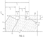
- FIG. 3 is a partial cross-sectional side view of the diamond table 204 of the cutting element 110 of FIG. 2 .
- the dimensions of the at least one recess 210 are exaggerated in order to better show the dimensions, shape, and orientation of the at least one recess 210.
- the at least one recess 210 may include opposing sidewalls 302 and a base wall 304.
- the at least one recess 210 may have a depth D and width W.
- an intersection of a radially outermost sidewall 302 of the recess 210 and the front cutting face 206 may be located some distance A from the outer peripheral edge 211 of the front cutting face 206 of the diamond table 204 when measured radially along an axis extending through a center axis of the cutting element 110 and across the front cutting face 206 of the diamond table 204.
- an intersection of a radially outermost sidewall 302 of a radially outermost recess 306 may be located some distance A from the outer peripheral edge 211 of the front cutting face 206 of the diamond table 204 when measured radially along an axis extending through a center axis of the cutting element 110 and across the front cutting face 206 of the diamond table 204.
- the distance A may be within a range of 0.5 mm to 4.0 mm.
- the distance A may be within a range of 0.5 mm to 2.0 mm.
- the distance A may be within a range of 0.5 mm to 1.5 mm.
- the distance A may be within a range of 1.0 mm to 1.5 mm.
- the distance A may be a percentage of a diameter of the cutting element 110.
- the distance A may be within a range of 4.0% to 42.0% of the diameter of the cutting element 110.
- the distance A may be within a range of 4.0% to 13.0% of the diameter of the cutting element 110.
- A may be within a range of 12.0% to 41% of the diameter of the cutting element 110.
- the diameter of the cutting element 110 may be within a range of 8 mm to 25 mm.
- the depth D of the recess 210 may be a measurement of a length extending from the front cutting face 206 of the diamond table 204 to the base wall 304 of the at least one recess 210.
- the at least one recess 210 may have a depth D within a range of 25.0 ⁇ m to 600 ⁇ m.
- the at least one recess 210 may have a depth D within a range of 25.0 ⁇ m to 300 ⁇ m.
- the at least one recess 210 may have a depth D within a range of 25.0 ⁇ m to 200 ⁇ m.
- the at least one recess 210 may have a depth D within a range of 25.0 ⁇ m to 150 ⁇ m. In yet other embodiments, the at least one recess 210 may have a depth D within a range of 25.0 ⁇ m to 100 ⁇ m. In yet other embodiments, the at least one recess 210 may have a depth D within a range of 25.0 ⁇ m to 50 ⁇ m. In yet other embodiments, the at least one recess 210 may have a depth D within a range of 75.0 ⁇ m to 150 ⁇ m.
- the diamond table 204 may contain a metal catalyst used to form the diamond table with an HPHT process, as referenced above.
- the metal catalyst may be substantially removed from a portion of the diamond table 204 , such as behind the front cutting face 206, inwardly of the lateral side surface 208 of the diamond table 204, or both.
- the at least one recess 210 may extend through an entire depth of the diamond table 204 from which catalyst has been removed, while in other embodiments, the at least one recess may be contained within the depth of substantially catalyst-free polycrystalline diamond.
- the metal catalyst may not be substantially removed from a portion of the diamond table 204, and the at least one recess 210 may be defined in a portion of the diamond table 204 containing a metal catalyst.
- the diamond table 204 may be cooled while the at least one recess 210 is formed in the front cutting face 206 of the diamond table 204.
- the front cutting face 206 may be cooled with a heat sink.
- the width W may be a measurement of a length between a first sidewall 302 and a second opposing sidewall 302 of the at least one recess 210.
- the at least one recess 210 may have a width W within a range of 25.0 ⁇ m to 650 ⁇ m.
- the at least one recess 210 may have a width W within a range of 25.0 ⁇ m to 300 ⁇ m.
- the at least one recess 210 may have a width W within a range of 250 ⁇ m to 200 ⁇ m.
- the at least one recess 210 may have a width W within a range of 25.0 ⁇ m to 150 ⁇ m.
- the at least one recess 210 may have a width W within a range of 25.0 ⁇ m to 100 ⁇ m. In yet other embodiments, the at least one recess 210 may have a width W within a range of 25.0 ⁇ m to 50 ⁇ m. In yet other embodiments, the at least one recess 210 may have a width W within a range of 100.0 ⁇ m to 200 ⁇ m. As will be appreciated by someone of ordinary skill in the art, in embodiments having more than one recess 210, the recesses 210 may have differing widths and depths relative to one another. Further, although the recesses 210 are shown as having linear walls and floors joined at sharp corners, it will be understood by those of ordinary skill in the art that such linearity and sharp definition between surfaces may not necessarily exist and are employed herein for purposes of clarity of explanation.
- a distance between intersections of adjacent sidewalls 302 of adjacent recesses 210 with the front cutting face 206 of the diamond table 204 may be some distance B.
- distance B may be within a range of 0.5 mm to 4.0 mm.
- the distance B may be within a range of 0.5 mm to 2.0 mm.
- the distance B may be within a range of 0.5 mm to 1.0 mm.
- a total distance C which may be a sum of the distance A, the widths W of the recesses 210, and any distance B between the recesses 210, may be less than 7.0 mm. In other embodiments, the total distance C may be less than 5.5 mm. In other embodiments, the total distance C may be less than 4.0 mm. In other embodiments, the total distance C may be less than 3.5 mm. In some embodiments, the total distance C may be a percentage of a diameter of the cutting element 110. For example, in some embodiments the distance C may be within a range of 12.0% to 44.0% of the diameter of the cutting element 110. For example, in some embodiments, the distance C may be within a range of 12.0% to 24.0% of the diameter of the cutting element 110. In other embodiments, C may be within a range of 38.0% to 44.0% of the diameter of the cutting element 110.
- surfaces of the sidewalls 302 of the at least one recess 210 may be at least generally perpendicular to the front cutting face 206 of the diamond table 204.
- the base wall 304 of the at least one recess 210 may be at least generally flat and a surface thereof may be at least generally parallel to the front cutting face 206 of the diamond table 204.
- the sidewalls 302 and base wall 304 of the at least one recess 210 are described herein as having generally flat surfaces, it is appreciated that the sidewalls 302 and base wall 304 of the at least one recess 210 may have curved, rounded, slanted, uneven, and/or irregular surfaces.
- the width W of the at least one recess 210 may be at least substantially uniform throughout the depth D of the at least one recess 210. In other embodiments, the width W of the at least one recess 210 may decrease as the depth D of the at least one recess 210 increases. For example, at width of the base wall 304 of the recess 210 may be smaller than the width W of the at least one recess 210 at the front cutting face 206 of the diamond table 204. In some embodiments, the intersections of the base wall 304 with the sidewalls 302 may be rounded to decrease stress concentrations around the at least one recess 210. However, it is understood that in some embodiments intersections of the base wall 304 with the sidewalls 302 of the at least one recess 210 may be sharp and/or irregular.
- the at least one recess 210 in the front cutting face 206 of the diamond table 204 may be configured to mitigate shallow spall propagation in the diamond table 204 of the cutting element 110.
- shallow spall refer to spalls formed by fractures that occur at least substantially parallel to the front cutting face 206 of the diamond table 204 at about a distance of 1.0 ⁇ m to 60.0 ⁇ m from the front cutting face 206 of the diamond table 204 of the cutting element 110.
- the at least one recess 210 may cause at least some resulting fractures in the diamond table 204 (e.g. breaks, cracks, chips, etc.) to cease propagating at the at least one recess 210.
- the at least one recess 210 may help to restrict shallow spalls to occurring in the diamond table 204 at least substantially only near the outer peripheral edge 211 of the front cutting face 206 instead of at a location in the diamond table 204 radially inward from the outer peripheral edge 211 of the front cutting face 206. As discussed in further detail below, this may result in the cutting element 110 being better suited for reuse after an initial spall during a drilling operation.
- the at least one recess 210 may mitigate shallow spall propagation in the diamond table 204 of the cutting element 110 by suppressing (e.g., disrupting, stopping, minimizing, mitigating, etc.) surface wave (e.g., Rayleigh waves) propagation through the diamond table 204 and across the front cutting face 206 of the diamond table 204 of the cutting element 110.
- surface wave e.g., Rayleigh waves
- Surface waves which are a type of acoustic wave that travel through solid material, can be produced by localized impacts to the solid material and can contribute to material failure (e.g., spalls).
- the at least one recess 210 may mitigate shallow spalling in the diamond table 204 of the cutting element 110.
- the at least one recess 210 may sufficiently mitigate shallow spalling such that during a drilling operation an initial spall occurring in the diamond table 204 may be restricted to only a portion of the front cutting face 206 of the diamond table 204.
- the at least one recess 210 may mitigate shallow spalling such that an initial spall in diamond table 204 only extends radially inward from the outer peripheral edge 211 of the front cutting face 206 a distance of less than 6.5 mm.
- the at least one recess 210 may mitigate shallow spalling such that an initial spall in the diamond table 204 only extends radially inward from the outer peripheral edge 211 of the front cutting face 206 a distance of less than 3.0 mm.
- the at least one recess 210 may mitigate shallow spalling such that an initial spall in the diamond table 204 only extends radially inward from the outer peripheral edge 211 of the front cutting face 206 a distance of less than 2.0 mm. In yet other embodiments, the at least one recess 210 may mitigate shallow spalling such that an initial spall in the diamond table 204 only extends radially inward from the outer peripheral edge 211 of the front cutting face 206 a distance of less than 1.5 mm.
- the cutting element 110 may be re-used. Therefore, restricting initial spalls on the front cutting face 206 of the diamond table 204 of the cutting element 110 such that the initial spalls only extend a certain distance radially inward from the outer peripheral edge 211 of the front cutting face 206 may greatly increase the reusability of cutting elements 110, which may lead to significant cost savings and an increased profit margin for users.
- the drilling operation may be stopped, and the cutting element 110 may be rotated (i.e., "spun") about its longitudinal axis within a cutting element pocket of a blade 104 in the drill bit 100.
- the cutting element 110 may be rotated within a cutting element pocket of a blade 104 by breaking a braze bond between the cutting element 110 and the pocket of a blade 104 through heat and rotating cutting element 110 within the cutting element pocket to present an unspalled portion of the diamond table 204 for contact with a formation.
- the cutting element 110 is again bonded the cutting element pocket of the blade 104, and the cutting element 110 may continue to be used in another drilling operation. Therefore, the cutting element 110 may be re-used such that replacing an entire cutting element 110 every time an initial spall occurs in a diamond table 204 of a cutting element 110 can be avoided.
- the at least one recess 210 may be formed in the front cutting face 206 of the diamond table 204 of the cutting element 110 through laser ablation.
- material may be removed from the front cutting face 206 of the diamond table 204 by irradiating the diamond table 204 with a laser beam.
- the material may be heated by the laser beam until the material evaporates, sublimates, or otherwise is removed from the diamond table 204.
- the at least one recess 210 is described herein as being formed through laser ablation, it will be appreciated that the at least one recess 210 could be formed through any number of methods such as, for example, drilling, cutting, milling, chemical etching, electric discharge machining (EDM), etc.
- EDM electric discharge machining
- the at least one recess 210 may be filled with a material differing from the material of the diamond table 204.
- the at least one recess 210 may be filled with silicon carbide after the at least one recess 210 is formed.
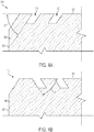
- FIGS. 4A and 4B are partial cross-sectional side views of diamond tables 204 of cutting elements 110 according to other embodiments of the present disclosure.
- the surfaces of the sidewalls 302 of the at least one recess 210 may be oriented at an acute angle ⁇ relative to the front cutting face 206 of the diamond table 204.
- the surfaces of the sidewalls 302 of the at least one recess 210 may be oriented at an acute angle relative to the front cutting face 206 in order to facilitate directing fractures to propagate in a certain direction relative to the front cutting face 206 of the diamond table 204.
- the surfaces of the sidewalls 302 of the at least one recess 210 may be oriented at an acute angle ⁇ relative to the front cutting face 206 such that when fractures occur within the diamond table 204, the fractures are more likely to propagate toward the lateral side surface 208 or center axis of the diamond table 204 depending on the orientation of the surfaces of the sidewalls 302 of the of the at least one recess 210.
- the surfaces of the sidewalls 302 of the of the at least one recess 210 may be oriented at an acute angle ⁇ relative to the front cutting face 206 such that when the front cutting face 206 fails the fracture propagates such that diamond table 204 self sharpens after failing.
- the surfaces of the sidewalls 302 of a first recess 210 may be oriented at least generally perpendicular to the front cutting face 206 and the surfaces of the sidewalls 302 of a second recess 210 may be oriented at an acute angle ⁇ relative to the front cutting face 206.
- surfaces of the sidewalls 302 of both the first recess 210 and the second recess 210 may be oriented at an acute angle ⁇ relative to the front cutting face 206.
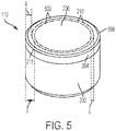
- FIG. 5 is a perspective view of the cutting element 110 of FIG. 2 having a plurality of recesses 210 in the front cutting face 206 of the diamond table 204 thereof.
- the plurality of recesses 210 in the front cutting face 206 of the diamond table 204 may form a plurality of concentric circles 502 that are concentric with a peripheral circle 508 defined by the outer peripheral edge 211 of the diamond table 204.
- the concentric circles 502 may be segmented.
- each concentric circle 502 may not be continuous but may be defined by a plurality of individual recesses 210 oriented in a shape of a circle.
- each concentric circle 502 may be segmented in order to mitigate shallow spall propagation in the diamond table 204 of the cutting element 110 while maintaining more of the structural integrity of the front cutting face 206 of the diamond table 204.
- the concentric circles 502 may be continuous. In other words, each concentric circle 502 maybe a single continuous recess 210.
- the distance X may be within a range of 1.0 mm to 1.5 mm. In some embodiments, the distance X may be a percentage of a diameter of the cutting element 110. For example, in some embodiments the distance X may be within a range of 4.0% to 42.0% of the diameter of the cutting element 110. For example, in some embodiments, the distance X may be within a range of 4.0% to 13.0% of the diameter of the cutting element 110. In other embodiments, X maybe within a range of 12.0% to 41% of the diameter of the cutting element 110.
- a distance between intersections of adjacent sidewalls 302 of adjacent concentric circles 502 and the front cutting face 206 of the diamond table 204 may be a distance E.
- the distance E may be within a range of 0.5 mm to 4.0 mm. In other embodiments, the distance E may be within a range of 0.5 mm to 2.0 mm. In other embodiments, the distance E may be within a range of 0.5 mm to 1.0 mm.
- a total distance F from the outer peripheral edge 211 of the front cutting face 206 of the diamond table 204 to a radially innermost sidewall of a radially innermost concentric circle 502 may be less than 7.0 mm. In other embodiments, the total distance F may be less than 5.5 mm. In yet other embodiments, the total distance F may be less than 4.0 mm. In other embodiments, the total distance F may be less than 3.5 mm.
- the total distance F may be a percentage of a diameter of the cutting element 110.
- the distance F may be within a range of 12.0% to 44.0% of the diameter of the cutting element 110.
- the distance F may be within a range of 12.0% to 24.0% of the diameter of the cutting element 110.
- F may be within a range of 38.0% to 44.0% of the diameter of the cutting element 110.
- the outermost concentric circle 502 may be segmented and at least one inner concentric circle 502 may be continuous. In other embodiments, the outermost concentric circle 502 may be continuous and at least one inner circle may be segmented. It will be appreciated by one of ordinary skill in the art that in some embodiments, the front cutting face 206 of the diamond table 204 may include only one circle defined by the at least one recess 210, and the only one circle may be concentric with the peripheral circle 508 defined by the outer peripheral edge 211 of the diamond table 204.
- FIGS. 6A-6E are top views of front cutting faces of diamond tables 204 of cutting elements 110 having at least one recess 210 therein according to other embodiments of the present disclosure.
- the front cutting face 206 of the diamond table 204 of the cutting element 110 may include a plurality of recesses 210 oriented in a plurality of segmented concentric circles 602 that are concentric to the peripheral circle 508 defined by the outer peripheral edge 211 of the front cutting face 206 of the diamond table 204.
- Each recess of the plurality of recesses 210 forming the plurality of segmented concentric circles 602 may have a longitudinal length that is aligned with a shape of a respective circle of which the recess is forming.
- an additional recess 608 may be defined between adjacent recesses 210 of the plurality of recesses 210 forming the plurality of segmented concentric circles 602.
- Each additional recess 608 may have a longitudinal length that is at least substantially perpendicular to the longitudinal lengths of the adjacent recesses 210 between which each additional recess 608 is oriented.
- the front cutting face 206 of the diamond table 204 may further include a radially innermost concentric circle 606 relative to the segmented concentric circles 602 formed by the plurality of recesses 210.
- an intersection of a radially outermost sidewall 302 of a radially outermost segmented concentric circle of the plurality of segmented concentric circles 602 and the front cutting face 206 of the diamond table 204 may be located some distance G from the outer peripheral edge 211 of the front cutting face 206 of the diamond table 204 when measured radially along an axis extending through a center axis of the cutting element 110 and across the front cutting face 206 of the diamond table 204.
- the distance G may be within a range of 0.5 mm to 4.0 mm. In other embodiments, the distance G may be within a range of 0.5 mm to 2.0 mm. In other embodiments, the distance G may be within a range of 0.5 mm to 1.5 mm. For example, in some embodiments, the distance G may be within a range of 1.0 mm to 1.5 mm.
- a distance between intersections of adjacent sidewalls 302 of adjacent segmented concentric circles 602 with the front cutting face 206 may be some distance H.
- distance H may be within a range of 0.5 mm to 4.0 mm. In other embodiments, the distance H may be within a range of 0.5 mm to 2.0 mm. In other embodiments, the distance H may be within a range of 0.5 mm to 1.0 mm.
- a total distance J which may be a distance between the outer peripheral edge 211 of the front cutting face 206 and an intersection of the radially innermost sidewall of the radially innermost concentric circle 606 with the front cutting face 206, may be less than 7.0 mm. In other embodiments, the total distance J maybe less than 5.5 mm. In yet other embodiments, the total distance J may be less than 4.0 mm. In other embodiments, the total distance J may be less than 3.5 mm. In some embodiments, the total distance J may be a percentage of a diameter of the cutting element 110. For example, in some embodiments the distance J may be within a range of 12.0% to 44.0% of the diameter of the cutting element 110. For example, in some embodiments, the distance J may be within a range of 12.0% to 24.0% of the diameter of the cutting element 110. In other embodiments, J may be within a range of 38.0% to 44.0% of the diameter of the cutting element 110.
- the front cutting face 206 of the diamond table 204 of the cutting element 110 may include a plurality of recesses 210, wherein each recess 210 of the plurality of recesses 210 forms a respective circle of a plurality of circles 618.
- the plurality of circles 618 may be oriented adjacent to each other and generally proximate the outer peripheral edge 211 of the front cutting face 206 of the diamond table 204.
- a diameter of the plurality of circles 618 may vary in size.
- a group of circles 618 most proximate the outer peripheral edge 211 of the front cutting face 206 of the diamond table 204 may have a larger diameter than a group of circles 618 that is less proximate the outer peripheral edge 211 of the front cutting face 206.
- the plurality of circles 618 may be located within a range of distances from the outer peripheral edge 211 of the front cutting face 206 when measured radially along an axis extending through a center axis of the cutting element 110 and across the front cutting face 206 of the diamond table 204.
- the plurality of circles 618 may be located within a range of 1.0 mm to 6.5 mm from the outer peripheral edge 211 of the front cutting face 206. In some embodiments, the plurality of circles 618 may be located within a range of 1.0 mm to 4.5 mm from the outer peripheral edge 211 of the front cutting face 206. In some embodiments, the plurality of circles 618 may be located within a range of 1.0 mm to 3.5 mm from the outer peripheral edge 211 of the front cutting face 206.
- the front cutting face 206 of the diamond table 204 of the cutting element 110 may include a plurality of linear recesses 620 that are oriented in a grid 622 across the front cutting face 206.
- the plurality of linear recesses 620 may be segmented.
- the plurality of linear recesses 620 may be continuous.
- some of the plurality of linear recesses 620 may be segmented and some of the linear recesses 620 may be continuous.
- the front cutting face 206 of the diamond table 204 of the cutting element 110 may include a sinusoidal wave shaped recess 624 that extends along an outer peripheral portion 632 of the front cutting face 206 of the diamond table 204 proximate the outer peripheral edge 211 of the front cutting face 206 of the diamond table 204.
- intersections of a radially outermost sidewall 302 of the sinusoidal wave shaped recess 624 with the front cutting face 206 of the diamond table 204 at crests 626 of the sinusoidal wave shaped recess 624 may be some distance M from the outer peripheral edge 211 of the front cutting face 206 when measured radially along an axis extending through a center axis of the cutting element 110 and across the front cutting face 206 of the diamond table 204.
- the distance M may be within a range of 0.5 mm to 4.0 mm.
- the distance M may be within a range of 0.5 mm to 2.0 mm.
- the distance M may be within a range of 0.5 mm to 1.5 mm.
- the distance M may be within a range of 1.0 mm to 1.5 mm.
- the front cutting face 206 of the diamond table 204 of the cutting element 110 may include two intersecting sinusoidal wave shaped recesses 624 that extend along the outer peripheral portion 632 of the front cutting face 206 of the diamond table 204 proximate the outer peripheral edge 211 of the front cutting face 206 of the diamond table 204.
- the two intersecting sinusoidal wave shaped recesses 624 may intersect at nodes 630 of the two intersecting sinusoidal wave shaped recesses 624.
- intersections of radially outermost sidewalls 302 of the two intersecting sinusoidal wave shaped recesses 624 with the front cutting face 206 of the diamond table 204 at crests 626 of two intersecting sinusoidal wave shaped recesses 624 may be some distance P from the outer peripheral edge 211 of the front cutting face 206 when measured radially along an axis extending through a center axis of the cutting element 110 and across the front cutting face 206 of the diamond table 204.
- the distance P may be within a range of 0.5 mm to 4.0 mm.
- the distance P may be within a range of 0.5 mm to 2.0 mm.
- the distance P may be within a range of 0.5 mm to 1.5 mm.
- the distance P may be within a range of 1.0 mm to 1.5 mm.
- intersections of radially innermost sidewalls 302 of the two intersecting sinusoidal wave shaped recesses 624 with the front cutting face 206 of the diamond table 204 at troughs 628 of the two intersecting sinusoidal wave shaped recesses 624 may be some distance Q from the outer peripheral edge 211 of the front cutting face 206 when measured radially along an axis extending through a center axis of the cutting element 110 and across the front cutting face 206 of the diamond table 204.
- the distance Q maybe less than 7.0 mm.
- the distance Q may be less than 5.5 mm.
- the distance Q may be less than 4.0 mm.
- the distance Q may be less than 3.5 mm.
- the at least one recess 210 may include any geometric shaped recess.
- the at least one recess 210 may include at least one recess in a shape of a rectangle, triangle, oval, arc, hexagon, octagon, etc.
- the at least one recess 210 may include at least one recess forming only a portion of a rectangle, triangle, oval, arc, hexagon, octagon, etc.
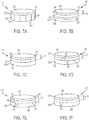
- FIGS. 7A-7F are perspective views of diamond tables 204 of cutting elements 110 according to other embodiments of the present disclosure.
- at least one recess 210 may be defined in the lateral side surface 208 of the diamond table 204.
- a plurality of recesses 210 may be defined in the lateral side surface 208.
- the longitudinal lengths of the plurality of recesses 210 may be oriented at least substantially parallel to each other and to a longitudinal length of the cutting element 110.
- the longitudinal lengths of the plurality of recesses 210 may be oriented at least substantially perpendicular to the front cutting face 206 of the diamond table 204.
- the plurality of recesses 210 may be at least substantially evenly spaced apart along the lateral side surface 208 of the diamond table 204. In some embodiments, the plurality of recesses 210 may extend from the outer peripheral edge 211 of the front cutting face 206 of the diamond table 204 to the interface 209 between the diamond table 204 and cutting element substrate 202. In other embodiments, the plurality of recesses 210 may only extend along a portion of lateral side surface 208 instead of extending from the outer peripheral edge 211 of the front cutting face of the diamond table 204 to the interface 209 between the diamond table 204 and cutting element substrate 202.
- the at least one recess 210 in the lateral side surface 208 of the diamond table 204 may be configured to mitigate failures (e.g., spalling, cracks, chips, breaks, etc.) in the lateral side surface 208 of the diamond table 204 of the cutting element 110 during use in a drilling operation.
- the at least one recess 210 may mitigate fractures in the lateral side surface 208 of the diamond table 204 of the cutting element 110 by tending to cause failures to terminate at the at least one recess 210.
- the at least one recess 210 may create a void of material barrier in the diamond table 204 such that when fractures in the diamond table 204 reach the at least one recess 210, the at least one recess 210 may cease propagation of the fracture, and any resulting chip may break off of the diamond table 204 at the at least one recess 210.
- the lateral side surface 208 includes a plurality of recesses 210 oriented parallel to each other, the plurality of recesses 210 may help to restrict fractures to occurring on the lateral side surface 208 within spaces between adjacent recesses 210 of the plurality of recesses 210 instead of propagating throughout the diamond table 204 beyond the adjacent recesses 210.
- the fracture may be at least partially kept between the two adjacent recesses 210.
- the at least one recess 210 may mitigate failures across the lateral side surface 208 of the diamond table 204 of the cutting element 110 by suppressing (e.g., disrupting, stopping, minimizing, etc.) Surface wave propagation in the diamond table 204 and across the lateral side surface 208 of the diamond table 204 of the cutting element 110.
- the plurality of recesses 210 may be segmented. In other embodiments, the plurality of recesses 210 may be continuous. In yet other embodiments, some of the plurality of recesses 210 may be segmented and some of the plurality of recesses 210 may be continuous.
- At least one linear recess 702 may be defined along the lateral side surface 208 of the diamond table 204, and a longitudinal length of the at least one linear recess 702 may be at least substantially parallel to the front cutting face 206 of the diamond table 204.
- the longitudinal length of the at least one linear recess 702 may be parallel to the peripheral circle 508 defined by the outer peripheral edge 211 of the front cutting face 206 of the diamond table 204.
- an intersection of an axially uppermost sidewall of the at least one linear recess 702 (when view from the perspective depicted in FIGS.
- the distance R may be within a range of 0.2 mm to 4.5 mm. In other embodiments, the distance R may be within a range of 0.5 mm to 2.0 mm. In other embodiments, the distance R may be within a range of 0.5 mm to 1.5 mm. For example, in some embodiments, the distance R may be within a range of 1.0 mm to 1.5 mm.
- the at least one linear recess 702 may help to restrict failures to occurring on the lateral side surface 208 at least substantially only near the front cutting face 206.
- the at least one linear recess 702 may help keep fractures from propagating from the front cutting face 206 to a location axially beyond the at least one linear recess 702 on the lateral side surface 208.
- the at least one linear recess 702 may be continuous as shown in FIG. 7C .
- the at least one linear recess 702 may be segmented as shown in FIG. 7B .
- the lateral side surface 208 may include a plurality of parallel linear recesses 702, as shown in FIG. 7B .
- the lateral side surface 208 of the diamond table 204 may include a sinusoidal wave shaped recess 724.
- an intersection of an axially uppermost sidewall of the sinusoidal wave shaped recess 724 (when view from the perspective depicted in FIGS. 7D and 7E relative to a surface upon which the diamond table 204 may be place) with the lateral side surface 208 at crests 726 of the sinusoidal wave shaped recess 724 may be located some distance S from the front cutting face 206 when measured axially from the front cutting face 206.
- the distance S may be within a range of 0.2 mm to 4.5 mm.
- the distance S may be within a range of 0.5 mm to 2.0 mm. In other embodiments, the distance S may be within a range of 0.5 mm to 1.5 mm. For example, in some embodiments, the distance S may be within a range of 1.0 mm to 1.5 mm.
- an intersection of an axially lowermost sidewall of the sinusoidal wave shaped recess 724 (when view from the perspective depicted in FIGS. 7D and 7E relative to a surface upon which the diamond table 204 may be place) with the lateral side surface 208 at the troughs 728 of the sinusoidal wave shaped recess 724 may be located some distance T from the front cutting face 206 when measured axially from the front cutting face 206.
- the distance T may be less than 7.5 mm. In other embodiments, the distance T may be less than 5.5 mm. In other embodiments, the distance T may be less than 4.0 mm. In other embodiments, the distance T may be less than 3.5 mm.
- the lateral side surface 208 of the diamond table 204 may include a plurality of arc recesses 730 oriented next to each other in a linear fashion.
- intersections of axially uppermost sidewalls 302 of uppermost portions of the arc recesses 730 (when view from the perspective depicted in FIG. 7F relative to a surface upon which the diamond table 204 may be place) and the lateral side surface 208 may be located some distance U from the front cutting face 206 when measured axially from the front cutting face 206.
- the distance U may be within a range of 0.2 mm to 4.5 mm.
- the distance U may be within a range of 0.5 mm to 2.0 mm. In other embodiments, the distance U may be within a range of 0.5 mm to 1.5 mm. For example, in some embodiments, the distance U may be within a range of 1.0 mm to 1.5 mm. In some embodiments, the plurality of arc recesses 730 may include a plurality of partial arc recesses.
- At least one recess 210 may be defined in both a front cutting face 206 of a diamond table 204 and in a lateral side surface 208 of a diamond table 204.
- At least one recess 210 may be defined in a front cutting face 206 of a diamond table 204 of a polished cutter element.
- the term "polished,” when used to describe a condition of a surface of a volume of superabrasive material or a substrate of a cutting element 110, means that the polished element has a surface finish roughness less than about 10 ⁇ in. (about 0.254 ⁇ m) root mean square (RMS). Surface waves may propagate through polished surfaces with a greater intensity than in non-polished surfaces. Therefore, defining at least one recess 210 in a front cutting face 206 of a polished diamond table 204 may help to mitigate shallow spalling in the front cutting face 206 of the polished diamond table 204.
- At least one recess 210 may be defined in the chamfer of the diamond table 204 and may help to mitigate failures (e.g., spalls, cracks, chips, etc.) in the chamfer of the diamond table 204 of a cutting element 110.
- Embodiments of cutting elements of the present disclosure may be used to attain one or more of the advantages described above.
Landscapes
- Engineering & Computer Science (AREA)
- Geology (AREA)
- Mining & Mineral Resources (AREA)
- Life Sciences & Earth Sciences (AREA)
- General Life Sciences & Earth Sciences (AREA)
- Fluid Mechanics (AREA)
- Mechanical Engineering (AREA)
- Environmental & Geological Engineering (AREA)
- Physics & Mathematics (AREA)
- Geochemistry & Mineralogy (AREA)
- Chemical & Material Sciences (AREA)
- Crystallography & Structural Chemistry (AREA)
- Processing Of Stones Or Stones Resemblance Materials (AREA)
- Drilling Tools (AREA)
- Earth Drilling (AREA)
Abstract
Description
- This application claims the benefit of the filing date of United States Provisional Patent Application Serial No.
14/656,036, filed March 12, 2015 - Embodiments of the present disclosure relate to earth-boring tools, cutting elements comprising diamond tables for such earth-boring tools, and related methods.
- Wellbores are formed in subterranean formations for various purposes including, for example, extraction of oil and gas from the subterranean formation and extraction of geothermal heat from the subterranean formation. Wellbores may be formed in a subterranean formation using a drill bit such as, for example, an earth-boring rotary drill bit. Different types of earth-boring rotary drill bits are known in the art including, for example, fixed-cutter bits (which are often referred to in the art as "drag" bits), rolling-cutter bits (which are often referred to in the art as "rock" bits), diamond-impregnated bits, and hybrid bits (which may include, for example, both fixed cutters and rolling cutters). The drill bit is rotated and advanced into the subterranean formation. As the drill bit rotates, the cutters or abrasive structures thereof cut, crush, shear, and/or abrade away the formation material to form the wellbore. A diameter of the wellbore drilled by the drill bit may be defined by the cutting structures disposed at the largest outer diameter of the drill bit.
- The drill bit is coupled, either directly or indirectly, to an end of what is referred to in the art as a "drill string," which comprises a series of elongated tubular segments connected end-to-end that extends into the wellbore from the surface of the formation. Often various tools and components, including the drill bit, may be coupled together at the distal end of the drill string at the bottom of the wellbore being drilled. This assembly of tools and components is referred to in the art as a "bottom-hole assembly" (BHA).
- The drill bit may be rotated within the wellbore by rotating the drill string from the surface of the formation, or the drill bit may be rotated by coupling the drill bit to a downhole motor, which is also coupled to the drill string and disposed proximate the bottom of the wellbore. The downhole motor may comprise, for example, a hydraulic Moineau-type motor having a shaft, to which the drill bit is mounted, that may be caused to rotate by pumping fluid (e.g., drilling mud or fluid) from the surface of the formation down through the center of the drill string, through the hydraulic motor, out from nozzles in the drill bit, and back up to the surface of the formation through the annular space between the outer surface of the drill string and the exposed surface of the formation within the wellbore.
- Spalls and cracks in the conventional polycrystalline diamond compact (PDC) cutting structures employed, for example, in fixed cutter and hybrid rotary drill bits and other drilling tools are a common problem when drilling with such cutting structures. Spalling in PDC tables of such cutting structures can greatly reduce the effectiveness of drill bits and other drilling tools and often renders a PDC table unusable such that the cutting structure including the PDC table must be completely replaced before the drill bit or other drilling tool is employed in another drilling operation.
- This summary does not identify key features or essential features of the claimed subject matter, nor does it limit the scope of the claimed subject matter in any way.
- Some embodiments of the present disclosure include a cutting element. The cutting element may include a diamond table having a front cutting face, the cutting face having an outer peripheral edge and at least one recess defined on the front cutting face of the diamond table. The at least one recess may include sidewalls intersecting with the front cutting face of the diamond table and extending to a base wall within the diamond table and wherein an intersection of a sidewall of the at least one recess and the front cutting face of the diamond table most proximate the outer peripheral edge of the front cutting face is located a distance of 0.5 mm to 4.0 mm from the outer peripheral edge of the front cutting face of the diamond table and wherein the at least one recess has a width within a range of 25.0 µm to 650 µm and a depth within a range of 25.0 µm to 600 µm.
- Some embodiments of the present disclosure include an earth-boring tool including a bit body and at least one cutting element secured to the bit body. The cutting element may include a diamond table having a front cutting face, the cutting face having an outer peripheral edge and at least one recess defined on the front cutting face of the diamond table. The at least one recess may include sidewalls intersecting with the front cutting face of the diamond table and extending to a base wall within the diamond table and wherein an intersection of a sidewall of the at least one recess and the front cutting face of the diamond table most proximate the outer peripheral edge of the front cutting face is located a distance of 0.5 mm to 4.0 mm from the outer peripheral edge of the front cutting face of the diamond table and wherein the at least one recess has a width within a range of 25.0 µm to 650 µm and a depth within a range of 25.0 µm to 600 µm.
- Some embodiments of the present disclosure include a method of reusing a cutting element configured to mitigate spalling. The method may include inserting a cutting element including a diamond table having at least one recess having a depth of 25.0 µm to 600 µm and a width of 25.0 µm to 650 µm defined on a front cutting face thereof into a pocket of an earth-boring tool. Then after performance of a drilling operation with the drill bit and after an occurrence of an initial spall in the diamond table of the cutting element, the cutting element may be rotated about a longitudinal axis thereof within the pocket to present an unspalled area of the front cutting face for drilling, and another drilling operation may be performed with the cutting element in the drill bit.
- While the specification concludes with claims particularly pointing out and distinctly claiming what are regarded as embodiments of the present disclosure, various features and advantages of this disclosure may be more readily ascertained from the following description of example embodiments of the disclosure provided with reference to the accompanying drawings.
-
FIG. 1 is a perspective view of an earth-boring drill bit with blades carrying cutting elements, according to an embodiment of the present disclosure; -
FIG. 2 is a perspective view of a cutting element including a front cutting face having a recess defined thereon, according to an embodiment of the present disclosure; -
FIG. 3 is a partial cross-sectional side view of a diamond table of the cutting element ofFIG. 2 ; -
FIGS. 4A and 4B are partial cross-sectional side views of diamond tables of cutting elements according to other embodiments of the present disclosure; -
FIG. 5 is a perspective view of the cutting element ofFIG 2 ; -
FIGS. 6A-6E are top views of front cutting faces of diamond tables having recesses defined thereon according to other embodiments of the present disclosure; and -
FIGS. 7A-7F are perspective views of diamond tables of cutting elements having recesses defined on a lateral side surface thereof according to other embodiments of the present disclosure; - The illustrations presented herein are not actual views of any particular earth-boring tool, drill bit, cutting element, or component of such a tool or bit, but are merely idealized representations which are employed to describe embodiments of the present disclosure.
- Embodiments of the present disclosure may include cutting elements having recesses defined in polycrystalline diamond compact (PDC) tables thereof that are configured to mitigate spalling and cracking in front cutting faces and lateral side surfaces (e.g., barrel faces) in the such diamond tables. For the sake of convenience, the term "diamond table" as used herein means and includes a polycrystalline diamond table comprising interbonded diamond grains formed in a high pressure, high temperature (HTHP) process, as is known to those of ordinary skill in the art. As used herein, the term "spall" means a fragment (e.g., chip, flake, piece, etc.) of a diamond table of a cutting element that is substantially two-dimensional (e.g., less than 60µm thick) and that has broken off of the diamond table due to a fracture in the diamond table that occurs at least substantially parallel to the front cutting surface of the diamond table of the cutting element such that the spall may include at least a portion of the cutting surface of the diamond table. However, it is appreciated that, in some cases, a "spall" can be up to 1 mm thick. Accordingly, as used herein, the term "spalling" means spalls breaking off of the diamond table. Some embodiments include a plurality of recesses defined in a front cutting face of a diamond table of a cutting element. Some embodiments include a plurality of recesses defined in a lateral side surface of a diamond table of a cutting element. In some embodiments, the recesses help to mitigate spalling in the diamond table proximate the front cutting face and/or lateral side surface of the diamond table by tending to cause spalls to terminate at the recesses. In some embodiments, the recesses help to mitigate spalling in the front cutting face and lateral side surface of the diamond table by suppressing surface wave propagation across the front cutting face and lateral side surface of the diamond table. In some embodiments, the recesses may sufficiently mitigate spalling such that after an initial spall in the diamond table proximate the front cutting face or lateral side surface, the cutting element may be rotated (i.e., "spun") and re-used in a drilling operation.
- As used herein, any relational term, such as "first," "second," "top," "bottom," "upper," "lower," "outer," "inner," is used for clarity and convenience in understanding the disclosure and accompanying drawings, and does not connote or depend on any specific preference, orientation, or order, except where the context clearly indicates otherwise. For example, these terms may refer to an orientation of elements of the apparatus relative to a surface upon which the apparatus may be disposed and operated (e.g., as illustrated in the figures).
- As used herein, the term "earth-boring tool" means and includes any tool used to remove formation material and form or enlarge a bore (e.g., a wellbore) through one or more subterranean formations by way of removing formation material. Earth-boring tools include, for example, rotary drill bits (e.g., fixed-cutter or "drag" bits and roller cone or "rock" bits), hybrid bits including both fixed cutters and roller elements, coring bits, percussion bits, bi-center bits, reamers (including expandable reamers and fixed-wing reamers), and other so-called "hole-opening" tools, etc.
- As used herein, the term "cutting element" means and includes any element of an earth-boring tool that is used to cut or otherwise disintegrate formation material when the earth-boring tool is used to form or enlarge a bore in the formation.
-
FIG. 1 illustrates an embodiment of an earth-boring tool of the present disclosure. The earth-boring tool ofFIG. 1 is a fixed-cutterrotary drill bit 100 having abit body 102 that includes a plurality ofblades 104 that project outwardly from thebit body 102 and are separated from one another byfluid courses 106. The portions of thefluid courses 106 that extend along the radial sides (the "gage" areas of the drill bit 100) are often referred to in the art as "junk slots." Thebit body 102 further includes a generally cylindrical internal fluid plenum, and fluid passageways (not visible) that extend through thebit body 102 to an exterior surface of thebit body 102.Nozzles 108 may be secured within the fluid passageways proximate the exterior surface of thebit body 102 for controlling the hydraulics of thedrill bit 100 during drilling. A plurality ofcutting elements 110 is mounted to each of theblades 104. - During a drilling operation, the
drill bit 100 may be coupled to a drill string (not shown). As thedrill bit 100 is rotated within the wellbore, drilling fluid may be pumped down the drill string, through the internal fluid plenum and fluid passageways within thebit body 102 of thedrill bit 100, and out from thedrill bit 100 through thenozzles 108. Formation cuttings generated by the cuttingelements 110 of thedrill bit 100 may be carried with the drilling fluid through thefluid courses 106, around thedrill bit 100, and back up the wellbore through the annular space within the wellbore outside the drill string. -
FIG. 2 is a perspective view of acutting element 110 of thedrill bit 100 ofFIG. 1 . The cuttingelement 110 may include acutting element substrate 202 and a volume of superabrasive material, such as a diamond table 204. The diamond table 204 may include afront cutting face 206, alateral side surface 208, and at least one recess 210 (e.g., disruption, groove, engraving, channel, etc.) defined in thefront cutting face 206. The diamond table 204 may be disposed on thecutting element substrate 202 and aninterface 209 may be defined between the cuttingelement substrate 202 and diamond table 204. Thefront cutting face 206 is the surface of the diamond table 204 on the side of the diamond table 204 opposite theinterface 209 between the cuttingelement substrate 202 and the diamond table 204. In some embodiments, thelateral side surface 208 may have a generally cylindrical shape and may extend from an outer peripheral edge 211 (e.g., cutting edge) of thefront cutting face 206 of the diamond table 204 to a peripheral edge of theinterface 209 between the cuttingelement substrate 202 and the diamond table 204. Optionally, the diamond table 204 may have a chamferededge 212 at an intersection of thefront cutting face 206 and thelateral side surface 208. Thechamfered edge 212 of the diamond table 204 shown inFIG. 2 has asingle chamfer surface 214, although thechamfered edge 212 may have additional chamfer surfaces, and such chamfer surfaces may be oriented at chamfer angles that differ from the chamfer angle of thechamfer surface 214 as illustrated in the figures, as known in the art. In some embodiments, the cuttingelement substrate 202 may have a generally cylindrical shape. The diamond table 204, as noted above, may comprise a polycrystalline diamond (PCD) material in the form of a PDC. - The cutting
element substrate 202 may be formed from a material that is relatively hard and resistant to wear. For example, the cuttingelement substrate 202 may be formed from and include a ceramic-metal composite material (which is often referred to as a "cermet" material). The cuttingelement substrate 202 may include a cemented carbide material, such as a cemented tungsten carbide material, in which tungsten carbide particles are cemented together in a metallic binder material. The metallic binder material may include, for example, cobalt, nickel, iron, or alloys and mixtures thereof. In some instances, the cuttingelement substrate 202 may comprise two or more pieces, one piece directly supporting the diamond table 204, and one or more additional pieces bonded thereto on a side of the substrate directly supporting the diamond table 204. In any case, the cuttingelements 110 may be secured by theirsubstrates 202 in pockets onblades 104 as depicted inFIG. 1 , such as by brazing. - In some embodiments, the at least one
recess 210 defined in thefront cutting face 206 of the diamond table 204 may be located proximate the outerperipheral edge 211 of the diamond table 204. In some embodiments, the at least onerecess 210 may include a plurality ofrecesses 210 defined in thefront cutting face 206 of the diamond table 204. As shown inFIG. 2 , in some embodiments, the at least onerecess 210 may be oriented in a pattern such as, for example, a plurality of concentric circles. The orientation and placement of the at least onerecess 210 in thefront cutting face 206 of the diamond table 204 are discussed in further detail below in regard toFIGS. 5 , and6A-6E . -
FIG. 3 is a partial cross-sectional side view of the diamond table 204 of the cuttingelement 110 ofFIG. 2 . The dimensions of the at least onerecess 210 are exaggerated in order to better show the dimensions, shape, and orientation of the at least onerecess 210. As shown inFIG. 3 , the at least onerecess 210 may include opposingsidewalls 302 and abase wall 304. Furthermore, the at least onerecess 210 may have a depth D and width W. In embodiments having only onerecess 210, an intersection of a radiallyoutermost sidewall 302 of therecess 210 and thefront cutting face 206 may be located some distance A from the outerperipheral edge 211 of thefront cutting face 206 of the diamond table 204 when measured radially along an axis extending through a center axis of the cuttingelement 110 and across thefront cutting face 206 of the diamond table 204. In embodiments having more than onerecess 210, an intersection of a radiallyoutermost sidewall 302 of a radiallyoutermost recess 306 may be located some distance A from the outerperipheral edge 211 of thefront cutting face 206 of the diamond table 204 when measured radially along an axis extending through a center axis of the cuttingelement 110 and across thefront cutting face 206 of the diamond table 204. In some embodiments, the distance A may be within a range of 0.5 mm to 4.0 mm. In other embodiments, the distance A may be within a range of 0.5 mm to 2.0 mm. In other embodiments, the distance A may be within a range of 0.5 mm to 1.5 mm. For example, in some embodiments, the distance A may be within a range of 1.0 mm to 1.5 mm. - In some embodiments, the distance A may be a percentage of a diameter of the cutting
element 110. For example, in some embodiments the distance A may be within a range of 4.0% to 42.0% of the diameter of the cuttingelement 110. For example, in some embodiments, the distance A may be within a range of 4.0% to 13.0% of the diameter of the cuttingelement 110. In other embodiments, A may be within a range of 12.0% to 41% of the diameter of the cuttingelement 110. In some embodiments, the diameter of the cuttingelement 110 may be within a range of 8 mm to 25 mm. - The depth D of the
recess 210 may be a measurement of a length extending from thefront cutting face 206 of the diamond table 204 to thebase wall 304 of the at least onerecess 210. In some embodiments, the at least onerecess 210 may have a depth D within a range of 25.0 µm to 600 µm. In other embodiments, the at least onerecess 210 may have a depth D within a range of 25.0 µm to 300 µm. In yet other embodiments, the at least onerecess 210 may have a depth D within a range of 25.0 µm to 200 µm. In yet other embodiments, the at least onerecess 210 may have a depth D within a range of 25.0 µm to 150 µm. In yet other embodiments, the at least onerecess 210 may have a depth D within a range of 25.0 µm to 100 µm. In yet other embodiments, the at least onerecess 210 may have a depth D within a range of 25.0 µm to 50 µm. In yet other embodiments, the at least onerecess 210 may have a depth D within a range of 75.0 µm to 150 µm. - In some embodiments, the diamond table 204 may contain a metal catalyst used to form the diamond table with an HPHT process, as referenced above. In such embodiments, the metal catalyst may be substantially removed from a portion of the diamond table 204 , such as behind the
front cutting face 206, inwardly of thelateral side surface 208 of the diamond table 204, or both. In some embodiments, the at least onerecess 210 may extend through an entire depth of the diamond table 204 from which catalyst has been removed, while in other embodiments, the at least one recess may be contained within the depth of substantially catalyst-free polycrystalline diamond. In other embodiments, the metal catalyst may not be substantially removed from a portion of the diamond table 204, and the at least onerecess 210 may be defined in a portion of the diamond table 204 containing a metal catalyst. In embodiments where the metal catalyst has not be substantially removed from a portion of the diamond table 204, the diamond table 204 may be cooled while the at least onerecess 210 is formed in thefront cutting face 206 of the diamond table 204. In some embodiments, thefront cutting face 206 may be cooled with a heat sink. - The width W may be a measurement of a length between a
first sidewall 302 and a second opposingsidewall 302 of the at least onerecess 210. In some embodiments, the at least onerecess 210 may have a width W within a range of 25.0 µm to 650 µm. In other embodiments, the at least onerecess 210 may have a width W within a range of 25.0 µm to 300 µm. In yet other embodiments, the at least onerecess 210 may have a width W within a range of 250 µm to 200 µm. In yet other embodiments, the at least onerecess 210 may have a width W within a range of 25.0 µm to 150 µm. In yet other embodiments, the at least onerecess 210 may have a width W within a range of 25.0 µm to 100 µm. In yet other embodiments, the at least onerecess 210 may have a width W within a range of 25.0 µm to 50 µm. In yet other embodiments, the at least onerecess 210 may have a width W within a range of 100.0 µm to 200 µm. As will be appreciated by someone of ordinary skill in the art, in embodiments having more than onerecess 210, therecesses 210 may have differing widths and depths relative to one another. Further, although therecesses 210 are shown as having linear walls and floors joined at sharp corners, it will be understood by those of ordinary skill in the art that such linearity and sharp definition between surfaces may not necessarily exist and are employed herein for purposes of clarity of explanation. - In embodiments having more than one
recess 210, as illustrated inFIG. 3 , a distance between intersections ofadjacent sidewalls 302 ofadjacent recesses 210 with thefront cutting face 206 of the diamond table 204 may be some distance B. In some embodiments, distance B may be within a range of 0.5 mm to 4.0 mm. In other embodiments, the distance B may be within a range of 0.5 mm to 2.0 mm. In other embodiments, the distance B may be within a range of 0.5 mm to 1.0 mm. - In some embodiments, a total distance C, which may be a sum of the distance A, the widths W of the
recesses 210, and any distance B between therecesses 210, may be less than 7.0 mm. In other embodiments, the total distance C may be less than 5.5 mm. In other embodiments, the total distance C may be less than 4.0 mm. In other embodiments, the total distance C may be less than 3.5 mm. In some embodiments, the total distance C may be a percentage of a diameter of the cuttingelement 110. For example, in some embodiments the distance C may be within a range of 12.0% to 44.0% of the diameter of the cuttingelement 110. For example, in some embodiments, the distance C may be within a range of 12.0% to 24.0% of the diameter of the cuttingelement 110. In other embodiments, C may be within a range of 38.0% to 44.0% of the diameter of the cuttingelement 110. - As shown in
FIG. 3 , surfaces of thesidewalls 302 of the at least onerecess 210 may be at least generally perpendicular to thefront cutting face 206 of the diamond table 204. Furthermore, thebase wall 304 of the at least onerecess 210 may be at least generally flat and a surface thereof may be at least generally parallel to thefront cutting face 206 of the diamond table 204. Moreover, although thesidewalls 302 andbase wall 304 of the at least onerecess 210 are described herein as having generally flat surfaces, it is appreciated that thesidewalls 302 andbase wall 304 of the at least onerecess 210 may have curved, rounded, slanted, uneven, and/or irregular surfaces. In some embodiments, the width W of the at least onerecess 210 may be at least substantially uniform throughout the depth D of the at least onerecess 210. In other embodiments, the width W of the at least onerecess 210 may decrease as the depth D of the at least onerecess 210 increases. For example, at width of thebase wall 304 of therecess 210 may be smaller than the width W of the at least onerecess 210 at thefront cutting face 206 of the diamond table 204. In some embodiments, the intersections of thebase wall 304 with thesidewalls 302 may be rounded to decrease stress concentrations around the at least onerecess 210. However, it is understood that in some embodiments intersections of thebase wall 304 with thesidewalls 302 of the at least onerecess 210 may be sharp and/or irregular. - During a drilling operation employing a
cutting element 110, the at least onerecess 210 in thefront cutting face 206 of the diamond table 204 may be configured to mitigate shallow spall propagation in the diamond table 204 of the cuttingelement 110. As used herein, the terms "shallow spall" refer to spalls formed by fractures that occur at least substantially parallel to thefront cutting face 206 of the diamond table 204 at about a distance of 1.0 µm to 60.0 µm from thefront cutting face 206 of the diamond table 204 of the cuttingelement 110. - In some embodiments, the at least one
recess 210 may mitigate shallow spall propagation in the diamond table 204 of the cuttingelement 110 by tending to cause spalls to terminate at the at least onerecess 210. In other words, the at least onerecess 210 may create a void of material barrier in the diamond table 204 such that when fractures in the diamond table 204 reach the at least onerecess 210, the at least onerecess 210 may cease propagation of the fracture, and any resulting spall may break off of the diamond table 204 at the at least onerecess 210. Accordingly, in a drilling operation when the cuttingelement 110 is impacting earth formations, the at least onerecess 210 may cause at least some resulting fractures in the diamond table 204 (e.g. breaks, cracks, chips, etc.) to cease propagating at the at least onerecess 210. As a result, when the at least onerecess 210 is defined proximate the outerperipheral edge 211 of thefront cutting face 206 of the diamond table 204, the at least onerecess 210 may help to restrict shallow spalls to occurring in the diamond table 204 at least substantially only near the outerperipheral edge 211 of thefront cutting face 206 instead of at a location in the diamond table 204 radially inward from the outerperipheral edge 211 of thefront cutting face 206. As discussed in further detail below, this may result in thecutting element 110 being better suited for reuse after an initial spall during a drilling operation. - In some embodiments, the at least one
recess 210 may mitigate shallow spall propagation in the diamond table 204 of the cuttingelement 110 by suppressing (e.g., disrupting, stopping, minimizing, mitigating, etc.) surface wave (e.g., Rayleigh waves) propagation through the diamond table 204 and across thefront cutting face 206 of the diamond table 204 of the cuttingelement 110. Surface waves, which are a type of acoustic wave that travel through solid material, can be produced by localized impacts to the solid material and can contribute to material failure (e.g., spalls). As a result, by suppressing surface wave propagation, the at least onerecess 210 may mitigate shallow spalling in the diamond table 204 of the cuttingelement 110. Furthermore, because surface waves travel through solid materials, by having a break in geometry in the solid material at least some surface waves may be suppressed. Testing performed by the Inventors has shown thatrecesses 210 having depths of 50.0 µm to 100.0 µm may significantly suppress surface wave propagation. However, the testing also shows that the effect of decreasing surface wave propagation does not continue to increase at the same rate as a depth of therecess 210 increases beyond about 100.0 µm. - In some embodiments, the at least one
recess 210 may sufficiently mitigate shallow spalling such that during a drilling operation an initial spall occurring in the diamond table 204 may be restricted to only a portion of thefront cutting face 206 of the diamond table 204. For example, in some embodiments, the at least onerecess 210 may mitigate shallow spalling such that an initial spall in diamond table 204 only extends radially inward from the outerperipheral edge 211 of the front cutting face 206 a distance of less than 6.5 mm. In other embodiments, the at least onerecess 210 may mitigate shallow spalling such that an initial spall in the diamond table 204 only extends radially inward from the outerperipheral edge 211 of the front cutting face 206 a distance of less than 3.0 mm. In yet other embodiments, the at least onerecess 210 may mitigate shallow spalling such that an initial spall in the diamond table 204 only extends radially inward from the outerperipheral edge 211 of the front cutting face 206 a distance of less than 2.0 mm. In yet other embodiments, the at least onerecess 210 may mitigate shallow spalling such that an initial spall in the diamond table 204 only extends radially inward from the outerperipheral edge 211 of the front cutting face 206 a distance of less than 1.5 mm. In yet other embodiments, the at least onerecess 210 may mitigate shallow spalling such that an initial spall in the diamond table 204 only extends radially inward from the outerperipheral edge 211 of the front cutting face 206 a distance of less than 1.1 mm. As a result, a lifespan (i.e., amount of time acutting element 110 remains sufficiently effective during use) may be increased for acutting element 110 by defining at least onerecess 210 in thefront cutting face 206 of the diamond table 204 of the cuttingelement 110 as described herein. - By restricting initial spalls on the
front cutting face 206 of the diamond table 204 of the cuttingelement 110 such that the initial spalls extend radially inward from the outerperipheral edge 211 of thefront cutting face 206 less than a certain distance as described herein, the cuttingelement 110 may be re-used. Therefore, restricting initial spalls on thefront cutting face 206 of the diamond table 204 of the cuttingelement 110 such that the initial spalls only extend a certain distance radially inward from the outerperipheral edge 211 of thefront cutting face 206 may greatly increase the reusability of cuttingelements 110, which may lead to significant cost savings and an increased profit margin for users. - For example, referring to
FIGS. 1 and3 together, during a drilling operation, after an initial spall has occurred in thefront cutting face 206 of the diamond table 204, the drilling operation may be stopped, and thecutting element 110 may be rotated (i.e., "spun") about its longitudinal axis within a cutting element pocket of ablade 104 in thedrill bit 100. In some embodiments, the cuttingelement 110 may be rotated within a cutting element pocket of ablade 104 by breaking a braze bond between the cuttingelement 110 and the pocket of ablade 104 through heat androtating cutting element 110 within the cutting element pocket to present an unspalled portion of the diamond table 204 for contact with a formation. In such an orientation, the cuttingelement 110 is again bonded the cutting element pocket of theblade 104, and thecutting element 110 may continue to be used in another drilling operation. Therefore, the cuttingelement 110 may be re-used such that replacing anentire cutting element 110 every time an initial spall occurs in a diamond table 204 of acutting element 110 can be avoided. - In some embodiments, the at least one
recess 210 may be formed in thefront cutting face 206 of the diamond table 204 of the cuttingelement 110 through laser ablation. For example, material may be removed from thefront cutting face 206 of the diamond table 204 by irradiating the diamond table 204 with a laser beam. In some embodiments, the material may be heated by the laser beam until the material evaporates, sublimates, or otherwise is removed from the diamond table 204. Although the at least onerecess 210 is described herein as being formed through laser ablation, it will be appreciated that the at least onerecess 210 could be formed through any number of methods such as, for example, drilling, cutting, milling, chemical etching, electric discharge machining (EDM), etc. - In some embodiments, after the at least one
recess 210 is formed, the at least onerecess 210 may be filled with a material differing from the material of the diamond table 204. For example, in some embodiments, the at least onerecess 210 may be filled with silicon carbide after the at least onerecess 210 is formed. -
FIGS. 4A and 4B are partial cross-sectional side views of diamond tables 204 of cuttingelements 110 according to other embodiments of the present disclosure. Referring toFIGS. 4A and 4B together, in some embodiments, the surfaces of thesidewalls 302 of the at least onerecess 210 may be oriented at an acute angle β relative to thefront cutting face 206 of the diamond table 204. The surfaces of thesidewalls 302 of the at least onerecess 210 may be oriented at an acute angle relative to thefront cutting face 206 in order to facilitate directing fractures to propagate in a certain direction relative to thefront cutting face 206 of the diamond table 204. For example, the surfaces of thesidewalls 302 of the at least onerecess 210 may be oriented at an acute angle β relative to thefront cutting face 206 such that when fractures occur within the diamond table 204, the fractures are more likely to propagate toward thelateral side surface 208 or center axis of the diamond table 204 depending on the orientation of the surfaces of thesidewalls 302 of the of the at least onerecess 210. In some embodiments, the surfaces of thesidewalls 302 of the of the at least onerecess 210 may be oriented at an acute angle β relative to thefront cutting face 206 such that when thefront cutting face 206 fails the fracture propagates such that diamond table 204 self sharpens after failing. - In embodiments having more than one
recess 210, the surfaces of thesidewalls 302 of afirst recess 210 may be oriented at least generally perpendicular to thefront cutting face 206 and the surfaces of thesidewalls 302 of asecond recess 210 may be oriented at an acute angle β relative to thefront cutting face 206. In other embodiments, surfaces of thesidewalls 302 of both thefirst recess 210 and thesecond recess 210 may be oriented at an acute angle β relative to thefront cutting face 206. -
FIG. 5 is a perspective view of the cuttingelement 110 ofFIG. 2 having a plurality ofrecesses 210 in thefront cutting face 206 of the diamond table 204 thereof. As shown inFIG. 3 , the plurality ofrecesses 210 in thefront cutting face 206 of the diamond table 204 may form a plurality ofconcentric circles 502 that are concentric with aperipheral circle 508 defined by the outerperipheral edge 211 of the diamond table 204. In some embodiments, theconcentric circles 502 may be segmented. In other words, eachconcentric circle 502 may not be continuous but may be defined by a plurality ofindividual recesses 210 oriented in a shape of a circle. The at least onerecess 210 forming eachconcentric circle 502 may be segmented in order to mitigate shallow spall propagation in the diamond table 204 of the cuttingelement 110 while maintaining more of the structural integrity of thefront cutting face 206 of the diamond table 204. In some embodiments, theconcentric circles 502 may be continuous. In other words, eachconcentric circle 502 maybe a singlecontinuous recess 210. - In some embodiments, an intersection of a radially
outermost sidewall 302 of the radially outermostconcentric circle 502 and thefront cutting face 206 of the diamond table 204 may be located a distance X from the outerperipheral edge 211 of thefront cutting face 206 of the diamond table 204 when measured radially along an axis extending through a center axis of the cuttingelement 110 and across thefront cutting face 206 of the diamond table 204. In some embodiments, the distance X may be within a range of 0.5 mm to 4.0 mm. In other embodiments, the distance X may be within a range of 0.5 mm to 2.0 mm. In other embodiments, the distance X may be within a range of 0.5 mm to 1.5 mm. For example, in some embodiments, the distance X may be within a range of 1.0 mm to 1.5 mm. In some embodiments, the distance X may be a percentage of a diameter of the cuttingelement 110. For example, in some embodiments the distance X may be within a range of 4.0% to 42.0% of the diameter of the cuttingelement 110. For example, in some embodiments, the distance X may be within a range of 4.0% to 13.0% of the diameter of the cuttingelement 110. In other embodiments, X maybe within a range of 12.0% to 41% of the diameter of the cuttingelement 110. - In some embodiments, a distance between intersections of
adjacent sidewalls 302 of adjacentconcentric circles 502 and thefront cutting face 206 of the diamond table 204 may be a distance E. In some embodiments, the distance E may be within a range of 0.5 mm to 4.0 mm. In other embodiments, the distance E may be within a range of 0.5 mm to 2.0 mm. In other embodiments, the distance E may be within a range of 0.5 mm to 1.0 mm. - In some embodiments, a total distance F from the outer
peripheral edge 211 of thefront cutting face 206 of the diamond table 204 to a radially innermost sidewall of a radially innermostconcentric circle 502 may be less than 7.0 mm. In other embodiments, the total distance F may be less than 5.5 mm. In yet other embodiments, the total distance F may be less than 4.0 mm. In other embodiments, the total distance F may be less than 3.5 mm. - In some embodiments, the total distance F may be a percentage of a diameter of the cutting
element 110. For example, in some embodiments the distance F may be within a range of 12.0% to 44.0% of the diameter of the cuttingelement 110. For example, in some embodiments, the distance F may be within a range of 12.0% to 24.0% of the diameter of the cuttingelement 110. In other embodiments, F may be within a range of 38.0% to 44.0% of the diameter of the cuttingelement 110. - In some embodiments, the outermost
concentric circle 502 may be segmented and at least one innerconcentric circle 502 may be continuous. In other embodiments, the outermostconcentric circle 502 may be continuous and at least one inner circle may be segmented. It will be appreciated by one of ordinary skill in the art that in some embodiments, thefront cutting face 206 of the diamond table 204 may include only one circle defined by the at least onerecess 210, and the only one circle may be concentric with theperipheral circle 508 defined by the outerperipheral edge 211 of the diamond table 204. -
FIGS. 6A-6E are top views of front cutting faces of diamond tables 204 of cuttingelements 110 having at least onerecess 210 therein according to other embodiments of the present disclosure. Referring toFIG. 6A , in some embodiments, thefront cutting face 206 of the diamond table 204 of the cuttingelement 110 may include a plurality ofrecesses 210 oriented in a plurality of segmentedconcentric circles 602 that are concentric to theperipheral circle 508 defined by the outerperipheral edge 211 of thefront cutting face 206 of the diamond table 204. Each recess of the plurality ofrecesses 210 forming the plurality of segmentedconcentric circles 602 may have a longitudinal length that is aligned with a shape of a respective circle of which the recess is forming. In some embodiments, anadditional recess 608 may be defined betweenadjacent recesses 210 of the plurality ofrecesses 210 forming the plurality of segmentedconcentric circles 602. Eachadditional recess 608 may have a longitudinal length that is at least substantially perpendicular to the longitudinal lengths of theadjacent recesses 210 between which eachadditional recess 608 is oriented. In some embodiments, thefront cutting face 206 of the diamond table 204 may further include a radially innermostconcentric circle 606 relative to the segmentedconcentric circles 602 formed by the plurality ofrecesses 210. - In some embodiments, an intersection of a radially
outermost sidewall 302 of a radially outermost segmented concentric circle of the plurality of segmentedconcentric circles 602 and thefront cutting face 206 of the diamond table 204 may be located some distance G from the outerperipheral edge 211 of thefront cutting face 206 of the diamond table 204 when measured radially along an axis extending through a center axis of the cuttingelement 110 and across thefront cutting face 206 of the diamond table 204. In some embodiments, the distance G may be within a range of 0.5 mm to 4.0 mm. In other embodiments, the distance G may be within a range of 0.5 mm to 2.0 mm. In other embodiments, the distance G may be within a range of 0.5 mm to 1.5 mm. For example, in some embodiments, the distance G may be within a range of 1.0 mm to 1.5 mm. - A distance between intersections of
adjacent sidewalls 302 of adjacent segmentedconcentric circles 602 with thefront cutting face 206 may be some distance H. In some embodiments, distance H may be within a range of 0.5 mm to 4.0 mm. In other embodiments, the distance H may be within a range of 0.5 mm to 2.0 mm. In other embodiments, the distance H may be within a range of 0.5 mm to 1.0 mm. - In some embodiments, a total distance J, which may be a distance between the outer
peripheral edge 211 of thefront cutting face 206 and an intersection of the radially innermost sidewall of the radially innermostconcentric circle 606 with thefront cutting face 206, may be less than 7.0 mm. In other embodiments, the total distance J maybe less than 5.5 mm. In yet other embodiments, the total distance J may be less than 4.0 mm. In other embodiments, the total distance J may be less than 3.5 mm. In some embodiments, the total distance J may be a percentage of a diameter of the cuttingelement 110. For example, in some embodiments the distance J may be within a range of 12.0% to 44.0% of the diameter of the cuttingelement 110. For example, in some embodiments, the distance J may be within a range of 12.0% to 24.0% of the diameter of the cuttingelement 110. In other embodiments, J may be within a range of 38.0% to 44.0% of the diameter of the cuttingelement 110. - Referring to
FIG. 6B , in some embodiments, thefront cutting face 206 of the diamond table 204 of the cuttingelement 110 may include a plurality ofrecesses 210, wherein eachrecess 210 of the plurality ofrecesses 210 forms a respective circle of a plurality ofcircles 618. The plurality ofcircles 618 may be oriented adjacent to each other and generally proximate the outerperipheral edge 211 of thefront cutting face 206 of the diamond table 204. In some embodiments, a diameter of the plurality ofcircles 618 may vary in size. For example, in some embodiments, a group ofcircles 618 most proximate the outerperipheral edge 211 of thefront cutting face 206 of the diamond table 204 may have a larger diameter than a group ofcircles 618 that is less proximate the outerperipheral edge 211 of thefront cutting face 206. In some embodiments, the plurality ofcircles 618 may be located within a range of distances from the outerperipheral edge 211 of thefront cutting face 206 when measured radially along an axis extending through a center axis of the cuttingelement 110 and across thefront cutting face 206 of the diamond table 204. For example, in some embodiments, the plurality ofcircles 618 may be located within a range of 1.0 mm to 6.5 mm from the outerperipheral edge 211 of thefront cutting face 206. In some embodiments, the plurality ofcircles 618 may be located within a range of 1.0 mm to 4.5 mm from the outerperipheral edge 211 of thefront cutting face 206. In some embodiments, the plurality ofcircles 618 may be located within a range of 1.0 mm to 3.5 mm from the outerperipheral edge 211 of thefront cutting face 206. - Referring to
FIG. 6C , in some embodiments, thefront cutting face 206 of the diamond table 204 of the cuttingelement 110 may include a plurality oflinear recesses 620 that are oriented in a grid 622 across thefront cutting face 206. In some embodiments, the plurality oflinear recesses 620 may be segmented. In other embodiments, the plurality oflinear recesses 620 may be continuous. In some embodiments, some of the plurality oflinear recesses 620 may be segmented and some of thelinear recesses 620 may be continuous. - Referring to
FIG. 6D , in some embodiments, thefront cutting face 206 of the diamond table 204 of the cuttingelement 110 may include a sinusoidal wave shapedrecess 624 that extends along an outerperipheral portion 632 of thefront cutting face 206 of the diamond table 204 proximate the outerperipheral edge 211 of thefront cutting face 206 of the diamond table 204. In some embodiments, intersections of a radiallyoutermost sidewall 302 of the sinusoidal wave shapedrecess 624 with thefront cutting face 206 of the diamond table 204 atcrests 626 of the sinusoidal wave shapedrecess 624 may be some distance M from the outerperipheral edge 211 of thefront cutting face 206 when measured radially along an axis extending through a center axis of the cuttingelement 110 and across thefront cutting face 206 of the diamond table 204. In some embodiments, the distance M may be within a range of 0.5 mm to 4.0 mm. In other embodiments, the distance M may be within a range of 0.5 mm to 2.0 mm. In other embodiments, the distance M may be within a range of 0.5 mm to 1.5 mm. For example, in some embodiments, the distance M may be within a range of 1.0 mm to 1.5 mm. - In some embodiments, intersections of a radially innermost sidewall of the sinusoidal wave shaped
recess 624 with thefront cutting face 206 of the diamond table 204 attroughs 628 of the sinusoidal wave shapedrecess 624 may be some distance N from the outerperipheral edge 211 of thefront cutting face 206 when measured radially along an axis extending through a center axis of the cuttingelement 110 and across thefront cutting face 206 of the diamond table 204. In some embodiments, the distance N may be less than 7.0 mm. In other embodiments, the distance N may be less than 5.5 mm. In other embodiments, the distance N may be less than 4.0 mm. In other embodiments, the distance N may be less than 3.5 mm. - In some embodiments, the
front cutting face 206 of the diamond table 204 of the cuttingelement 110 may include two or more concentric the sinusoidal wave shaped recesses 624. In some embodiments, the sinusoidal wave shapedrecess 624 orrecesses 210 may be segmented. In some embodiments, the sinusoidal wave shapedrecess 624 orrecesses 210 may be continuous. In some embodiments having two or more concentric the sinusoidal wave shapedrecesses 624, a first sinusoidal wave shapedrecess 624 may be segmented and a second sinusoidal wave shapedrecess 624 may be continuous. - Referring to
FIG. 6E , in some embodiments, thefront cutting face 206 of the diamond table 204 of the cuttingelement 110 may include two intersecting sinusoidal wave shapedrecesses 624 that extend along the outerperipheral portion 632 of thefront cutting face 206 of the diamond table 204 proximate the outerperipheral edge 211 of thefront cutting face 206 of the diamond table 204. The two intersecting sinusoidal wave shapedrecesses 624 may intersect atnodes 630 of the two intersecting sinusoidal wave shaped recesses 624. In some embodiments, intersections of radiallyoutermost sidewalls 302 of the two intersecting sinusoidal wave shapedrecesses 624 with thefront cutting face 206 of the diamond table 204 atcrests 626 of two intersecting sinusoidal wave shapedrecesses 624 may be some distance P from the outerperipheral edge 211 of thefront cutting face 206 when measured radially along an axis extending through a center axis of the cuttingelement 110 and across thefront cutting face 206 of the diamond table 204. In some embodiments, the distance P may be within a range of 0.5 mm to 4.0 mm. In other embodiments, the distance P may be within a range of 0.5 mm to 2.0 mm. In other embodiments, the distance P may be within a range of 0.5 mm to 1.5 mm. For example, in some embodiments, the distance P may be within a range of 1.0 mm to 1.5 mm. - In some embodiments, intersections of radially
innermost sidewalls 302 of the two intersecting sinusoidal wave shapedrecesses 624 with thefront cutting face 206 of the diamond table 204 attroughs 628 of the two intersecting sinusoidal wave shapedrecesses 624 may be some distance Q from the outerperipheral edge 211 of thefront cutting face 206 when measured radially along an axis extending through a center axis of the cuttingelement 110 and across thefront cutting face 206 of the diamond table 204. In some embodiments, the distance Q maybe less than 7.0 mm. In other embodiments, the distance Q may be less than 5.5 mm. In other embodiments, the distance Q may be less than 4.0 mm. In other embodiments, the distance Q may be less than 3.5 mm. - Although the at least one
recess 210 is described herein as having the above described shapes and orientations, it is understood that the at least onerecess 210 may include any geometric shaped recess. For example, the at least onerecess 210 may include at least one recess in a shape of a rectangle, triangle, oval, arc, hexagon, octagon, etc. Furthermore, the at least onerecess 210 may include at least one recess forming only a portion of a rectangle, triangle, oval, arc, hexagon, octagon, etc. -
FIGS. 7A-7F are perspective views of diamond tables 204 of cuttingelements 110 according to other embodiments of the present disclosure. Referring toFIG. 7A , in some embodiments of the present disclosure, at least onerecess 210 may be defined in thelateral side surface 208 of the diamond table 204. In some embodiments, a plurality ofrecesses 210 may be defined in thelateral side surface 208. In some embodiments, the longitudinal lengths of the plurality ofrecesses 210 may be oriented at least substantially parallel to each other and to a longitudinal length of the cuttingelement 110. In other words, the longitudinal lengths of the plurality ofrecesses 210 may be oriented at least substantially perpendicular to thefront cutting face 206 of the diamond table 204. In some embodiments, the plurality ofrecesses 210 may be at least substantially evenly spaced apart along thelateral side surface 208 of the diamond table 204. In some embodiments, the plurality ofrecesses 210 may extend from the outerperipheral edge 211 of thefront cutting face 206 of the diamond table 204 to theinterface 209 between the diamond table 204 and cuttingelement substrate 202. In other embodiments, the plurality ofrecesses 210 may only extend along a portion oflateral side surface 208 instead of extending from the outerperipheral edge 211 of the front cutting face of the diamond table 204 to theinterface 209 between the diamond table 204 and cuttingelement substrate 202. - In some embodiments, the at least one
recess 210 in thelateral side surface 208 of the diamond table 204 may be configured to mitigate failures (e.g., spalling, cracks, chips, breaks, etc.) in thelateral side surface 208 of the diamond table 204 of the cuttingelement 110 during use in a drilling operation. In some embodiments, the at least onerecess 210 may mitigate fractures in thelateral side surface 208 of the diamond table 204 of the cuttingelement 110 by tending to cause failures to terminate at the at least onerecess 210. In other words, the at least onerecess 210 may create a void of material barrier in the diamond table 204 such that when fractures in the diamond table 204 reach the at least onerecess 210, the at least onerecess 210 may cease propagation of the fracture, and any resulting chip may break off of the diamond table 204 at the at least onerecess 210. As a result, when thelateral side surface 208 includes a plurality ofrecesses 210 oriented parallel to each other, the plurality ofrecesses 210 may help to restrict fractures to occurring on thelateral side surface 208 within spaces betweenadjacent recesses 210 of the plurality ofrecesses 210 instead of propagating throughout the diamond table 204 beyond theadjacent recesses 210. In other words, if thelateral side surface 208 fractures, wherein the fracture begins between twoadjacent recesses 210, the fracture may be at least partially kept between the twoadjacent recesses 210. In some embodiments, the at least onerecess 210 may mitigate failures across thelateral side surface 208 of the diamond table 204 of the cuttingelement 110 by suppressing (e.g., disrupting, stopping, minimizing, etc.) Surface wave propagation in the diamond table 204 and across thelateral side surface 208 of the diamond table 204 of the cuttingelement 110. - In some embodiments, the plurality of
recesses 210 may be segmented. In other embodiments, the plurality ofrecesses 210 may be continuous. In yet other embodiments, some of the plurality ofrecesses 210 may be segmented and some of the plurality ofrecesses 210 may be continuous. - Referring to
FIGS. 7B and 7C together, in some embodiments of the present disclosure, at least onelinear recess 702 may be defined along thelateral side surface 208 of the diamond table 204, and a longitudinal length of the at least onelinear recess 702 may be at least substantially parallel to thefront cutting face 206 of the diamond table 204. In other words, the longitudinal length of the at least onelinear recess 702 may be parallel to theperipheral circle 508 defined by the outerperipheral edge 211 of thefront cutting face 206 of the diamond table 204. In some embodiments, an intersection of an axially uppermost sidewall of the at least one linear recess 702 (when view from the perspective depicted inFIGS. 7B and 7C relative to a surface upon which the diamond table 204 may be place) with thelateral side surface 208 may be located some distance R from thefront cutting face 206 when measured axially from thefront cutting face 206. In some embodiments, the distance R may be within a range of 0.2 mm to 4.5 mm. In other embodiments, the distance R may be within a range of 0.5 mm to 2.0 mm. In other embodiments, the distance R may be within a range of 0.5 mm to 1.5 mm. For example, in some embodiments, the distance R may be within a range of 1.0 mm to 1.5 mm. - As a result, when the at least one
linear recess 702 is defined proximate thefront cutting face 206 of the diamond table 204 on thelateral side surface 208 of the diamond table 204, the at least onelinear recess 702 may help to restrict failures to occurring on thelateral side surface 208 at least substantially only near thefront cutting face 206. In other words, the at least onelinear recess 702 may help keep fractures from propagating from thefront cutting face 206 to a location axially beyond the at least onelinear recess 702 on thelateral side surface 208. In some embodiments the at least onelinear recess 702 may be continuous as shown inFIG. 7C . In other embodiments, the at least onelinear recess 702 may be segmented as shown inFIG. 7B . In some embodiments, thelateral side surface 208 may include a plurality of parallellinear recesses 702, as shown inFIG. 7B . - Referring to
FIGS. 7D and 7E together, in some embodiments of the present disclosure, thelateral side surface 208 of the diamond table 204 may include a sinusoidal wave shapedrecess 724. In some embodiments, an intersection of an axially uppermost sidewall of the sinusoidal wave shaped recess 724 (when view from the perspective depicted inFIGS. 7D and 7E relative to a surface upon which the diamond table 204 may be place) with thelateral side surface 208 atcrests 726 of the sinusoidal wave shapedrecess 724 may be located some distance S from thefront cutting face 206 when measured axially from thefront cutting face 206. In some embodiments, the distance S may be within a range of 0.2 mm to 4.5 mm. In other embodiments, the distance S may be within a range of 0.5 mm to 2.0 mm. In other embodiments, the distance S may be within a range of 0.5 mm to 1.5 mm. For example, in some embodiments, the distance S may be within a range of 1.0 mm to 1.5 mm. - In some embodiments, an intersection of an axially lowermost sidewall of the sinusoidal wave shaped recess 724 (when view from the perspective depicted in
FIGS. 7D and 7E relative to a surface upon which the diamond table 204 may be place) with thelateral side surface 208 at thetroughs 728 of the sinusoidal wave shapedrecess 724 may be located some distance T from thefront cutting face 206 when measured axially from thefront cutting face 206. In some embodiments, the distance T may be less than 7.5 mm. In other embodiments, the distance T may be less than 5.5 mm. In other embodiments, the distance T may be less than 4.0 mm. In other embodiments, the distance T may be less than 3.5 mm. - Referring to
FIG. 7F , in some embodiments of the present disclosure, thelateral side surface 208 of the diamond table 204 may include a plurality of arc recesses 730 oriented next to each other in a linear fashion. In some embodiments, intersections of axiallyuppermost sidewalls 302 of uppermost portions of the arc recesses 730 (when view from the perspective depicted inFIG. 7F relative to a surface upon which the diamond table 204 may be place) and thelateral side surface 208 may be located some distance U from thefront cutting face 206 when measured axially from thefront cutting face 206. In some embodiments, the distance U may be within a range of 0.2 mm to 4.5 mm. In other embodiments, the distance U may be within a range of 0.5 mm to 2.0 mm. In other embodiments, the distance U may be within a range of 0.5 mm to 1.5 mm. For example, in some embodiments, the distance U may be within a range of 1.0 mm to 1.5 mm. In some embodiments, the plurality of arc recesses 730 may include a plurality of partial arc recesses. - Referring to
FIGS. 5 and7A-7F together, in some embodiments, at least onerecess 210 may be defined in both afront cutting face 206 of a diamond table 204 and in alateral side surface 208 of a diamond table 204. - Referring again to
FIGS. 1 and2 , in some embodiments at least onerecess 210 may be defined in afront cutting face 206 of a diamond table 204 of a polished cutter element. As used herein, the term "polished," when used to describe a condition of a surface of a volume of superabrasive material or a substrate of acutting element 110, means that the polished element has a surface finish roughness less than about 10 µin. (about 0.254 µm) root mean square (RMS). Surface waves may propagate through polished surfaces with a greater intensity than in non-polished surfaces. Therefore, defining at least onerecess 210 in afront cutting face 206 of a polished diamond table 204 may help to mitigate shallow spalling in thefront cutting face 206 of the polished diamond table 204. - In some embodiments, at least one
recess 210 may be defined in the chamfer of the diamond table 204 and may help to mitigate failures (e.g., spalls, cracks, chips, etc.) in the chamfer of the diamond table 204 of acutting element 110. - Embodiments of cutting elements of the present disclosure may be used to attain one or more of the advantages described above.
- Although the foregoing description contains many specifics, these are not to be construed as limiting the scope of the present disclosure, but merely as providing certain example embodiments. Similarly, other embodiments of the disclosure may be devised which are within the scope of the present disclosure. For example, features described herein with reference to one embodiment may also be combined with features of other embodiments described herein. The scope of the disclosure is, therefore, indicated and limited only by the appended claims, rather than by the foregoing description. All additions, deletions, and modifications to the devices, apparatuses, systems and methods, as disclosed herein, which fall within the meaning and scope of the claims, are encompassed by the present disclosure.
-
- 1. A cutting element, comprising a diamond table having a front cutting face, the cutting face having an outer peripheral edge;
at least one recess defined on the front cutting face of the diamond table and comprising:- sidewalls intersecting with the front cutting face of the diamond table and extending to a base wall within the diamond table; and
- wherein an intersection of a sidewall of the at least one recess and the front cutting face of the diamond table most proximate the outer peripheral edge of the front cutting face is located a distance of 0.5 mm to 4.0 mm from the outer peripheral edge of the front cutting face of the diamond table and wherein the at least one recess has a width within a range of 25.0 µm to 650 µm and a depth within a range of 25.0 µm to 600 µm.
- 2. The cutting element of embodiment 1, wherein the at least one recess has a width within the range of 50.0 µm to 650 µm and a depth within a range of 50.0 µm to 600 µm.
- 3. The cutting element of embodiment 1, wherein the at least one recess has a width within the range of 100 µm to 200 µm and a depth within a range of 75.0 µm to 155 µm.
- 4. The cutting element of embodiment 1, wherein the intersection of the sidewall of the at least one recess and front cutting face of the diamond table most proximate the outer peripheral edge is located a distance of 1.0 mm to 3.0 mm from the outer peripheral edge of the front cutting face of the diamond table.
- 5. The cutting element of embodiment 1, wherein the diamond table further comprises at least substantially cylindrical lateral side surface having at least one recess defined thereon.
- 6. The cutting element of embodiment 1, wherein the at least one recess comprises at least one circular recess on the front cutting face of the diamond table.
- 7. The cutting element of embodiment 1, wherein the at least one recess comprises a sinusoidal wave shaped recess.
- 8. The cutting element of embodiment 1, wherein the at least one recess comprises a plurality of concentric, circular recesses that are concentric to a peripheral circle defined by an outer peripheral edge of the front cutting face of the diamond table.
- 9. The cutting element of embodiment 1, wherein the sidewalls of the at least one recess are oriented at an acute angle relative to the front cutting face of the diamond table.
- 10. The cutting element of embodiment 1, wherein the base wall of the at least one recess is at least generally flat and parallel to the front cutting face of the diamond table.
- 11. An earth-boring tool, comprising a bit body and at least one cutting element secured to the bit body and comprising:
a diamond table having a front cutting face, the cutting face having an outer peripheral edge at least one recess defined on the front cutting face of the diamond table and comprising:
sidewalls intersecting with the front cutting face of the diamond table and extending to a base wall within the diamond table, and wherein an intersection of a sidewall of the at least one recess and the front cutting face of the diamond table most proximate the outer peripheral edge of the front cutting face is located a distance of 0.5 mm to 4.0 mm from the outer peripheral edge of the front cutting face of the diamond table and wherein the at least one recess has a width within a range of 25.0 µm to 650 µm and a depth within a range of 25.0 µm to 600 µm. - 12. The earth-boring tool of embodiment 11, wherein the at least one recess has a width within the range of 50.0 µm to 650 µm and a depth within a range of 50.0 µm to 600 µm.
- 13. The earth-boring tool of embodiment 11, wherein the at least one recess has a width within the range of 100 µm to 200 µm and a depth within a range of 75.0 µm to 155 µm.
- 14. The earth-boring tool of embodiment 11, wherein the intersection of the sidewall of the at least one recess and front cutting face of the diamond table most proximate the outer peripheral edge is located a distance of 1.0 mm to 3.0 mm from the outer peripheral edge of the front cutting face of the diamond table.
- 15. The earth-boring tool of embodiment 11, wherein the intersection of the sidewall of the at least one recess and front cutting face of the diamond table most proximate the outer peripheral edge is located a distance of 1.0 mm to 1.5 mm from the outer peripheral edge of the front cutting face of the diamond table.
- 16. The earth-boring tool of embodiment 11, wherein the intersection of the sidewall of the at least one recess and front cutting face of the diamond table most proximate the outer peripheral edge is located a distance of 4.0% to 42.0% of a diameter of the at least one cutting element from the outer peripheral edge of the front cutting face of the diamond table.
- 17. The earth-boring tool of embodiment 11, wherein the diamond table of the at least one cutting element further comprises at least substantially cylindrical lateral side surface having at least one recess defined thereon.
- 18. The earth-boring tool of embodiment 17, wherein the at least one recess defined on the at least substantially cylindrical lateral side surface of the diamond table comprises a sinusoidal wave shaped recess.
- 19. A method of reusing a cutting element configured to mitigate spalling, the method comprising:
- inserting a cutting element having a diamond table having at least one recess having a depth of 25.0 µm to 600 µm and a width of 25.0 µm to 650 µm defined on a front cutting face thereof into a pocket of an earth-boring tool;
- after performance of a drilling operation with the drill bit and after an occurrence of an initial spall in the diamond table of the cutting element, rotating the cutting element about a longitudinal axis thereof within the pocket to present an unspalled area of the front cutting face for drilling; and
- performing another drilling operation with the cutting element in the drill bit.
- 20. The method of embodiment 19, wherein inserting a cutting element having a diamond table having at least one recess having a depth of 25.0 µm to 600 µm and a width of 25.0 µm to 650 µm defined on a front cutting face thereof into a blade of a drill bit comprises inserting a cutting element having a diamond table having at least one recess having a depth of 50.0 µm to 600 µm and width of 25.0 µm to 650 µm defined on a front cutting face thereof into a blade of a drill bit.
Claims (15)
- A cutting element, comprising:a diamond table having a front cutting face, the cutting face having an outer peripheral edge; anda plurality of recesses defined on the front cutting face of the diamond table, and comprising sidewalls intersecting with the front cutting face of the diamond table and extending to a base wall within the diamond table;wherein the plurality of recesses form a segmented concentric circle, the segmented concentric circle being concentric with a peripheral circle defined by the outer peripheral edge;and wherein an intersection of a sidewall of each of the plurality of recesses and the front cutting face of the diamond table most proximate the outer peripheral edge of the front cutting face is located a distance of 0.5 mm to 4.0 mm from the outer peripheral edge of the front cutting face of the diamond table, and wherein each of the recesses has a width within a range of 25.0 µm to 650 µm and a depth within a range of 25.0 µm to 600 µm.
- The cutting element of claim 1, wherein each of the plurality of recesses has a width within the range of 50.0 µm to 650 µm and a depth within a range of 50.0 µm to 600 µm, and optionally a width within the range of 100 µm to 200 µm and a depth within a range of 75.0 µm to 155 µm.
- The cutting element of claim 1, wherein the diamond table further comprises at least one substantially cylindrical lateral side surface having at least one recess defined thereon.
- The cutting element of claim 1, wherein the plurality of recesses further comprises at least one concentric circular recess that is concentric to the peripheral circle defined by the outer peripheral edge.
- The cutting element of claim 1, wherein the plurality of recesses further forms at least one additional segmented concentric circle concentric with the peripheral circle defined by the outer peripheral edge.
- The cutting element of claim 1, wherein the sidewalls of at least one recess of the plurality of recesses are oriented at an acute angle relative to the front cutting face of the diamond table.
- The cutting element of claim 1, wherein the base wall of at least one recess of the plurality of recesses is at least generally flat and parallel to the front cutting face of the diamond table.
- An earth-boring tool, comprising:a bit body; andat least one cutting element as claimed in claim 1.
- The earth-boring tool of claim 8, wherein each of the plurality of recesses has a width within the range of 50.0 µm to 650 µm and a depth within a range of 50.0 µm to 600 µm, and optionally a width within the range of 100 µm to 200 µm and a depth within a range of 75.0 µm to 155 µm.
- The cutting element of claim 1, or the earth-boring tool of claim 8, wherein the intersection of the sidewall of each of the plurality of recesses and front cutting face of the diamond table most proximate the outer peripheral edge is located a distance of 1.0 mm to 3.0 mm from the outer peripheral edge of the front cutting face of the diamond table.
- The earth-boring tool of claim 8, wherein the intersection of the sidewall of each of the plurality of recesses and front cutting face of the diamond table most proximate the outer peripheral edge is located a distance of 1.0 mm to 1.5 mm from the outer peripheral edge of the front cutting face of the diamond table.
- The earth-boring tool of claim 8, wherein the intersection of the sidewall of each of the plurality of recesses and front cutting face of the diamond table most proximate the outer peripheral edge is located a distance of 4.0% to 42.0% of a diameter of the at least one cutting element from the outer peripheral edge of the front cutting face of the diamond table.
- The earth-boring tool of claim 8, wherein the diamond table of the at least one cutting element further comprises at least one substantially cylindrical lateral side surface having at least one recess defined thereon.
- A method of reusing a cutting element configured to mitigate spalling, the method comprising:inserting a cutting element having a diamond table having a plurality of recesses each having a depth of 25.0 µm to 600 µm and a width of 25.0 µm to 650 µm defined on a front cutting face thereof into a pocket of an earth-boring tool, wherein the plurality of recesses form a segmented concentric circle, the segmented concentric circle being concentric with a peripheral circle defined by the outer peripheral edge;after performance of a drilling operation with the drill bit and after an occurrence of an initial spall in the diamond table of the cutting element, rotating the cutting element about a longitudinal axis thereof within the pocket to present an unspalled area of the front cutting face for drilling; andperforming another drilling operation with the cutting element in the drill bit.
- The method of claim 14, wherein inserting a cutting element having a diamond table having a plurality of recesses each having a depth of 25.0 µm to 600 µm and a width of 25.0 µm to 650 µm defined on a front cutting face thereof into a blade of a drill bit comprises inserting a cutting element having a diamond table having a plurality of recesses each having a depth of 50.0 µm to 600 µm and width of 25.0 µm to 650 µm defined on a front cutting face thereof into a blade of a drill bit.
Applications Claiming Priority (3)
| Application Number | Priority Date | Filing Date | Title |
|---|---|---|---|
| US14/656,036 US10465447B2 (en) | 2015-03-12 | 2015-03-12 | Cutting elements configured to mitigate diamond table failure, earth-boring tools including such cutting elements, and related methods |
| PCT/US2016/022020 WO2016145318A1 (en) | 2015-03-12 | 2016-03-11 | Cutting elements configured to mitigate diamond table failure, earth-boring tools including such cutting elements, and related methods |
| EP16762602.7A EP3268571B1 (en) | 2015-03-12 | 2016-03-11 | Cutting elements configured to mitigate diamond table failure, earth-boring tools including such cutting elements, and related methods |
Related Parent Applications (2)
| Application Number | Title | Priority Date | Filing Date |
|---|---|---|---|
| EP16762602.7A Division-Into EP3268571B1 (en) | 2015-03-12 | 2016-03-11 | Cutting elements configured to mitigate diamond table failure, earth-boring tools including such cutting elements, and related methods |
| EP16762602.7A Division EP3268571B1 (en) | 2015-03-12 | 2016-03-11 | Cutting elements configured to mitigate diamond table failure, earth-boring tools including such cutting elements, and related methods |
Publications (1)
| Publication Number | Publication Date |
|---|---|
| EP3623571A1 true EP3623571A1 (en) | 2020-03-18 |
Family
ID=56879432
Family Applications (2)
| Application Number | Title | Priority Date | Filing Date |
|---|---|---|---|
| EP19205156.3A Withdrawn EP3623571A1 (en) | 2015-03-12 | 2016-03-11 | Cutting elements configured to mitigate diamond table failure, earth-boring tools including such cutting elements, and related methods |
| EP16762602.7A Not-in-force EP3268571B1 (en) | 2015-03-12 | 2016-03-11 | Cutting elements configured to mitigate diamond table failure, earth-boring tools including such cutting elements, and related methods |
Family Applications After (1)
| Application Number | Title | Priority Date | Filing Date |
|---|---|---|---|
| EP16762602.7A Not-in-force EP3268571B1 (en) | 2015-03-12 | 2016-03-11 | Cutting elements configured to mitigate diamond table failure, earth-boring tools including such cutting elements, and related methods |
Country Status (6)
| Country | Link |
|---|---|
| US (1) | US10465447B2 (en) |
| EP (2) | EP3623571A1 (en) |
| KR (1) | KR20180008399A (en) |
| CN (1) | CN107429539B (en) |
| WO (1) | WO2016145318A1 (en) |
| ZA (1) | ZA201706387B (en) |
Families Citing this family (15)
| Publication number | Priority date | Publication date | Assignee | Title |
|---|---|---|---|---|
| US10465447B2 (en) | 2015-03-12 | 2019-11-05 | Baker Hughes, A Ge Company, Llc | Cutting elements configured to mitigate diamond table failure, earth-boring tools including such cutting elements, and related methods |
| US10287824B2 (en) | 2016-03-04 | 2019-05-14 | Baker Hughes Incorporated | Methods of forming polycrystalline diamond |
| US10400517B2 (en) * | 2017-05-02 | 2019-09-03 | Baker Hughes, A Ge Company, Llc | Cutting elements configured to reduce impact damage and related tools and methods |
| US11292750B2 (en) | 2017-05-12 | 2022-04-05 | Baker Hughes Holdings Llc | Cutting elements and structures |
| US11396688B2 (en) | 2017-05-12 | 2022-07-26 | Baker Hughes Holdings Llc | Cutting elements, and related structures and earth-boring tools |
| US11536091B2 (en) | 2018-05-30 | 2022-12-27 | Baker Hughes Holding LLC | Cutting elements, and related earth-boring tools and methods |
| US10570668B2 (en) | 2018-07-27 | 2020-02-25 | Baker Hughes, A Ge Company, Llc | Cutting elements configured to reduce impact damage and mitigate polycrystalline, superabrasive material failure earth-boring tools including such cutting elements, and related methods |
| US10577870B2 (en) * | 2018-07-27 | 2020-03-03 | Baker Hughes, A Ge Company, Llc | Cutting elements configured to reduce impact damage related tools and methods—alternate configurations |
| US12078015B2 (en) * | 2019-08-30 | 2024-09-03 | Schlumberger Technology Corporation | Polycrystalline diamond cutting element having improved cutting efficiency |
| EP4048852A4 (en) | 2019-10-25 | 2024-02-28 | National Oilwell DHT, L.P. | DRILL CUTTING ELEMENT AND DRILL BIT THEREOF |
| CN114981518A (en) * | 2020-02-05 | 2022-08-30 | 贝克休斯油田作业有限责任公司 | Cutter Geometry Utilizing Spherical Cuts |
| CN114929986B (en) * | 2020-02-05 | 2025-12-09 | 贝克休斯油田作业有限责任公司 | Cutting element with improved mechanical efficiency |
| WO2022170352A1 (en) | 2021-02-05 | 2022-08-11 | Baker Hughes Oilfield Operations Llc | Cutting elements for earth-boring tools, and methods of manufacturing earth-boring tools |
| US11992881B2 (en) | 2021-10-25 | 2024-05-28 | Baker Hughes Oilfield Operations Llc | Selectively leached thermally stable cutting element in earth-boring tools, earth-boring tools having selectively leached cutting elements, and related methods |
| US11920409B2 (en) | 2022-07-05 | 2024-03-05 | Baker Hughes Oilfield Operations Llc | Cutting elements, earth-boring tools including the cutting elements, and methods of forming the earth-boring tools |
Citations (4)
| Publication number | Priority date | Publication date | Assignee | Title |
|---|---|---|---|---|
| US5054246A (en) * | 1988-09-09 | 1991-10-08 | Cornelius Phaal | Abrasive compacts |
| US20110171414A1 (en) * | 2010-01-14 | 2011-07-14 | National Oilwell DHT, L.P. | Sacrificial Catalyst Polycrystalline Diamond Element |
| WO2013040123A1 (en) * | 2011-09-16 | 2013-03-21 | Baker Hughes Incorporated | Cutting elements for earth-boring tools, earth-boring tools including such cutting elements and related methods |
| US20140246253A1 (en) * | 2012-05-01 | 2014-09-04 | Baker Hughes Incorporated | Cutting elements for earth-boring tools, earth-boring tools including such cutting elements, and related methods |
Family Cites Families (53)
| Publication number | Priority date | Publication date | Assignee | Title |
|---|---|---|---|---|
| CA1244589A (en) | 1983-02-24 | 1988-11-08 | Union Carbide Corporation | Low-temperature crosslinking of water-borne resins |
| DE68905106T2 (en) | 1988-06-28 | 1993-09-02 | Camco Drilling Group Ltd | CUTTING ELEMENTS FOR ROTARY DRILL CHISELS. |
| US4989578A (en) * | 1989-08-30 | 1991-02-05 | Lebourg Maurice P | Method for forming diamond cutting elements for a diamond drill bit |
| US5172778A (en) | 1991-11-14 | 1992-12-22 | Baker-Hughes, Inc. | Drill bit cutter and method for reducing pressure loading of cutters |
| US5437343A (en) | 1992-06-05 | 1995-08-01 | Baker Hughes Incorporated | Diamond cutters having modified cutting edge geometry and drill bit mounting arrangement therefor |
| US5706906A (en) | 1996-02-15 | 1998-01-13 | Baker Hughes Incorporated | Superabrasive cutting element with enhanced durability and increased wear life, and apparatus so equipped |
| GB9621217D0 (en) * | 1996-10-11 | 1996-11-27 | Camco Drilling Group Ltd | Improvements in or relating to preform cutting elements for rotary drill bits |
| JP3461267B2 (en) | 1997-08-11 | 2003-10-27 | 大日精化工業株式会社 | Polycarbodiimide compound, method for producing the same, resin composition, and method for treating article |
| US6672406B2 (en) | 1997-09-08 | 2004-01-06 | Baker Hughes Incorporated | Multi-aggressiveness cuttting face on PDC cutters and method of drilling subterranean formations |
| US6045440A (en) | 1997-11-20 | 2000-04-04 | General Electric Company | Polycrystalline diamond compact PDC cutter with improved cutting capability |
| US6196340B1 (en) | 1997-11-28 | 2001-03-06 | U.S. Synthetic Corporation | Surface geometry for non-planar drill inserts |
| US6527069B1 (en) | 1998-06-25 | 2003-03-04 | Baker Hughes Incorporated | Superabrasive cutter having optimized table thickness and arcuate table-to-substrate interfaces |
| CA2276841C (en) | 1998-07-07 | 2004-12-14 | Smith International, Inc. | Unplanar non-axisymmetric inserts |
| US6708764B2 (en) | 2002-07-12 | 2004-03-23 | Cdx Gas, L.L.C. | Undulating well bore |
| US6447560B2 (en) | 1999-02-19 | 2002-09-10 | Us Synthetic Corporation | Method for forming a superabrasive polycrystalline cutting tool with an integral chipbreaker feature |
| US6550556B2 (en) | 2000-12-07 | 2003-04-22 | Smith International, Inc | Ultra hard material cutter with shaped cutting surface |
| US6510910B2 (en) | 2001-02-09 | 2003-01-28 | Smith International, Inc. | Unplanar non-axisymmetric inserts |
| WO2004007901A1 (en) | 2002-07-10 | 2004-01-22 | Diamond Innovations, Inc. | Cutting tools with two-slope profile |
| US6935444B2 (en) | 2003-02-24 | 2005-08-30 | Baker Hughes Incorporated | Superabrasive cutting elements with cutting edge geometry having enhanced durability, method of producing same, and drill bits so equipped |
| US7954570B2 (en) | 2004-02-19 | 2011-06-07 | Baker Hughes Incorporated | Cutting elements configured for casing component drillout and earth boring drill bits including same |
| US7726420B2 (en) | 2004-04-30 | 2010-06-01 | Smith International, Inc. | Cutter having shaped working surface with varying edge chamfer |
| US7475744B2 (en) | 2005-01-17 | 2009-01-13 | Us Synthetic Corporation | Superabrasive inserts including an arcuate peripheral surface |
| US7740090B2 (en) | 2005-04-04 | 2010-06-22 | Smith International, Inc. | Stress relief feature on PDC cutter |
| US7942218B2 (en) | 2005-06-09 | 2011-05-17 | Us Synthetic Corporation | Cutting element apparatuses and drill bits so equipped |
| GB2433524B (en) | 2005-12-14 | 2011-09-28 | Smith International | Cutting elements having catting edges with continuous varying radil and bits incorporating the same |
| WO2008102324A1 (en) | 2007-02-23 | 2008-08-28 | Element Six (Production) (Pty) Ltd | Cutting elements |
| TW200835864A (en) | 2007-02-27 | 2008-09-01 | Jian-Dih Jeng | Simplified fluid dynamic bearing design |
| JP5222004B2 (en) | 2007-04-09 | 2013-06-26 | 株式会社ブリヂストン | Sealing film and solar cell using the same |
| US8061456B2 (en) | 2007-08-27 | 2011-11-22 | Baker Hughes Incorporated | Chamfered edge gage cutters and drill bits so equipped |
| JP5315838B2 (en) | 2008-07-31 | 2013-10-16 | 日本ゼオン株式会社 | Adhesive composition, composite, and automotive member |
| US8833492B2 (en) | 2008-10-08 | 2014-09-16 | Smith International, Inc. | Cutters for fixed cutter bits |
| US20100288564A1 (en) | 2009-05-13 | 2010-11-18 | Baker Hughes Incorporated | Cutting element for use in a drill bit for drilling subterranean formations |
| WO2011005996A2 (en) * | 2009-07-08 | 2011-01-13 | Baker Hughes Incorporated | Cutting element for a drill bit used in drilling subterranean formations |
| EP3514319B1 (en) | 2009-10-02 | 2020-04-08 | Baker Hughes, a GE company, LLC | Cutting elements configured to generate shear lips during use in cutting, earth-boring tools including such cutting elements, and methods of forming and using such cutting elements and earth-boring tools |
| EP2510180B1 (en) | 2009-12-08 | 2018-05-09 | Smith International, Inc. | Polycrystalline diamond cutting element structure |
| US8505634B2 (en) | 2009-12-28 | 2013-08-13 | Baker Hughes Incorporated | Earth-boring tools having differing cutting elements on a blade and related methods |
| EP2561171B1 (en) | 2010-04-23 | 2018-01-10 | Baker Hughes, a GE company, LLC | Cutting elements for earth-boring tools, earth-boring tools including such cutting elements and related methods |
| CA2830675A1 (en) | 2011-03-28 | 2012-10-04 | Diamond Innovations, Inc. | Cutting element having modified surface |
| US9243452B2 (en) | 2011-04-22 | 2016-01-26 | Baker Hughes Incorporated | Cutting elements for earth-boring tools, earth-boring tools including such cutting elements, and related methods |
| US9650837B2 (en) | 2011-04-22 | 2017-05-16 | Baker Hughes Incorporated | Multi-chamfer cutting elements having a shaped cutting face and earth-boring tools including such cutting elements |
| US9482057B2 (en) | 2011-09-16 | 2016-11-01 | Baker Hughes Incorporated | Cutting elements for earth-boring tools, earth-boring tools including such cutting elements and related methods |
| US9062505B2 (en) * | 2011-06-22 | 2015-06-23 | Us Synthetic Corporation | Method for laser cutting polycrystalline diamond structures |
| US8807247B2 (en) | 2011-06-21 | 2014-08-19 | Baker Hughes Incorporated | Cutting elements for earth-boring tools, earth-boring tools including such cutting elements, and methods of forming such cutting elements for earth-boring tools |
| US9404310B1 (en) | 2012-03-01 | 2016-08-02 | Us Synthetic Corporation | Polycrystalline diamond compacts including a domed polycrystalline diamond table, and applications therefor |
| CN202850865U (en) * | 2012-06-21 | 2013-04-03 | 四川深远石油钻井工具有限公司 | Module cutting teeth with drilling specific pressure controllable |
| US9140072B2 (en) | 2013-02-28 | 2015-09-22 | Baker Hughes Incorporated | Cutting elements including non-planar interfaces, earth-boring tools including such cutting elements, and methods of forming cutting elements |
| US9702198B1 (en) | 2013-03-12 | 2017-07-11 | Us Synthetic Corporation | Polycrystalline diamond compacts and methods of fabricating same |
| US10287825B2 (en) | 2014-03-11 | 2019-05-14 | Smith International, Inc. | Cutting elements having non-planar surfaces and downhole cutting tools using such cutting elements |
| HUE045748T2 (en) | 2014-07-01 | 2020-01-28 | Millennium Pharm Inc | Heteroaryl compounds useful as inhibitors of sumo activating enzyme |
| US10465447B2 (en) | 2015-03-12 | 2019-11-05 | Baker Hughes, A Ge Company, Llc | Cutting elements configured to mitigate diamond table failure, earth-boring tools including such cutting elements, and related methods |
| KR102437366B1 (en) | 2017-02-09 | 2022-08-29 | 유에스 신써틱 코포레이션 | Energy machined polycrystalline diamond compacts and related methods |
| US10400517B2 (en) | 2017-05-02 | 2019-09-03 | Baker Hughes, A Ge Company, Llc | Cutting elements configured to reduce impact damage and related tools and methods |
| US11098532B2 (en) | 2017-09-05 | 2021-08-24 | Schlumberger Technology Corporation | Cutting elements having non-planar surfaces and tools incorporating the same |
-
2015
- 2015-03-12 US US14/656,036 patent/US10465447B2/en not_active Expired - Fee Related
-
2016
- 2016-03-11 EP EP19205156.3A patent/EP3623571A1/en not_active Withdrawn
- 2016-03-11 WO PCT/US2016/022020 patent/WO2016145318A1/en not_active Ceased
- 2016-03-11 KR KR1020177027054A patent/KR20180008399A/en not_active Ceased
- 2016-03-11 EP EP16762602.7A patent/EP3268571B1/en not_active Not-in-force
- 2016-03-11 CN CN201680015014.8A patent/CN107429539B/en not_active Expired - Fee Related
-
2017
- 2017-09-21 ZA ZA2017/06387A patent/ZA201706387B/en unknown
Patent Citations (4)
| Publication number | Priority date | Publication date | Assignee | Title |
|---|---|---|---|---|
| US5054246A (en) * | 1988-09-09 | 1991-10-08 | Cornelius Phaal | Abrasive compacts |
| US20110171414A1 (en) * | 2010-01-14 | 2011-07-14 | National Oilwell DHT, L.P. | Sacrificial Catalyst Polycrystalline Diamond Element |
| WO2013040123A1 (en) * | 2011-09-16 | 2013-03-21 | Baker Hughes Incorporated | Cutting elements for earth-boring tools, earth-boring tools including such cutting elements and related methods |
| US20140246253A1 (en) * | 2012-05-01 | 2014-09-04 | Baker Hughes Incorporated | Cutting elements for earth-boring tools, earth-boring tools including such cutting elements, and related methods |
Also Published As
| Publication number | Publication date |
|---|---|
| CN107429539A (en) | 2017-12-01 |
| EP3268571B1 (en) | 2020-04-29 |
| US10465447B2 (en) | 2019-11-05 |
| WO2016145318A1 (en) | 2016-09-15 |
| EP3268571A1 (en) | 2018-01-17 |
| US20160265285A1 (en) | 2016-09-15 |
| CN107429539B (en) | 2020-04-21 |
| EP3268571A4 (en) | 2018-11-14 |
| KR20180008399A (en) | 2018-01-24 |
| ZA201706387B (en) | 2019-12-18 |
Similar Documents
| Publication | Publication Date | Title |
|---|---|---|
| EP3268571B1 (en) | Cutting elements configured to mitigate diamond table failure, earth-boring tools including such cutting elements, and related methods | |
| US10570668B2 (en) | Cutting elements configured to reduce impact damage and mitigate polycrystalline, superabrasive material failure earth-boring tools including such cutting elements, and related methods | |
| US10577870B2 (en) | Cutting elements configured to reduce impact damage related tools and methods—alternate configurations | |
| EP3191677B1 (en) | Multi-chamfer cutting elements having a shaped cutting face, earth-boring tools including such cutting elements. | |
| US8794356B2 (en) | Shaped cutting elements on drill bits and other earth-boring tools, and methods of forming same | |
| CN112601873B (en) | Downhole tool with improved cutter arrangement | |
| CN103025460A (en) | Superabrasive cutting element with cutting edge geometry for enhanced durability and cutting efficiency and drill bit so equipped | |
| US12049788B2 (en) | Cutter geometry utilizing spherical cutouts | |
| WO2024112905A1 (en) | Cutting elements and geometries for reduced vibrations, earth-boring tools, and related methods | |
| US20190284877A1 (en) | Earth-boring tools and methods of forming earth-boring tools | |
| WO2015111016A1 (en) | Drill bit for drilling a borehole | |
| US12577839B2 (en) | Devices, systems, and methods of a cutting element in a bit |
Legal Events
| Date | Code | Title | Description |
|---|---|---|---|
| PUAI | Public reference made under article 153(3) epc to a published international application that has entered the european phase |
Free format text: ORIGINAL CODE: 0009012 |
|
| STAA | Information on the status of an ep patent application or granted ep patent |
Free format text: STATUS: THE APPLICATION HAS BEEN PUBLISHED |
|
| AC | Divisional application: reference to earlier application |
Ref document number: 3268571 Country of ref document: EP Kind code of ref document: P |
|
| AK | Designated contracting states |
Kind code of ref document: A1 Designated state(s): AL AT BE BG CH CY CZ DE DK EE ES FI FR GB GR HR HU IE IS IT LI LT LU LV MC MK MT NL NO PL PT RO RS SE SI SK SM TR |
|
| STAA | Information on the status of an ep patent application or granted ep patent |
Free format text: STATUS: REQUEST FOR EXAMINATION WAS MADE |
|
| 17P | Request for examination filed |
Effective date: 20200918 |
|
| RBV | Designated contracting states (corrected) |
Designated state(s): AL AT BE BG CH CY CZ DE DK EE ES FI FR GB GR HR HU IE IS IT LI LT LU LV MC MK MT NL NO PL PT RO RS SE SI SK SM TR |
|
| STAA | Information on the status of an ep patent application or granted ep patent |
Free format text: STATUS: THE APPLICATION IS DEEMED TO BE WITHDRAWN |
|
| 18D | Application deemed to be withdrawn |
Effective date: 20221001 |