EP3623251A1 - Stabilizer device for rail vehicles, especially a roll stabilizer - Google Patents
Stabilizer device for rail vehicles, especially a roll stabilizer Download PDFInfo
- Publication number
- EP3623251A1 EP3623251A1 EP19193998.2A EP19193998A EP3623251A1 EP 3623251 A1 EP3623251 A1 EP 3623251A1 EP 19193998 A EP19193998 A EP 19193998A EP 3623251 A1 EP3623251 A1 EP 3623251A1
- Authority
- EP
- European Patent Office
- Prior art keywords
- stabilizer device
- coupling
- coupling element
- arrangement
- fastening
- Prior art date
- Legal status (The legal status is an assumption and is not a legal conclusion. Google has not performed a legal analysis and makes no representation as to the accuracy of the status listed.)
- Granted
Links
- 239000003381 stabilizer Substances 0.000 title claims abstract description 54
- 230000008878 coupling Effects 0.000 claims abstract description 77
- 238000010168 coupling process Methods 0.000 claims abstract description 77
- 238000005859 coupling reaction Methods 0.000 claims abstract description 77
- 238000013016 damping Methods 0.000 claims description 14
- 229920001971 elastomer Polymers 0.000 claims description 6
- 230000000295 complement effect Effects 0.000 claims description 4
- 239000000806 elastomer Substances 0.000 claims description 2
- 239000000463 material Substances 0.000 claims description 2
- 230000002093 peripheral effect Effects 0.000 claims description 2
- 230000008901 benefit Effects 0.000 description 7
- 238000005096 rolling process Methods 0.000 description 6
- 239000012530 fluid Substances 0.000 description 4
- 238000011161 development Methods 0.000 description 3
- 230000018109 developmental process Effects 0.000 description 3
- 230000000694 effects Effects 0.000 description 3
- 230000005489 elastic deformation Effects 0.000 description 3
- 239000003795 chemical substances by application Substances 0.000 description 2
- 238000012423 maintenance Methods 0.000 description 2
- 238000007789 sealing Methods 0.000 description 2
- 239000007787 solid Substances 0.000 description 2
- 230000006641 stabilisation Effects 0.000 description 2
- 238000011105 stabilization Methods 0.000 description 2
- 230000007704 transition Effects 0.000 description 2
- 230000009471 action Effects 0.000 description 1
- 230000015572 biosynthetic process Effects 0.000 description 1
- 238000010276 construction Methods 0.000 description 1
- 230000001419 dependent effect Effects 0.000 description 1
- 230000006872 improvement Effects 0.000 description 1
- 238000004519 manufacturing process Methods 0.000 description 1
- 230000002028 premature Effects 0.000 description 1
- 230000000087 stabilizing effect Effects 0.000 description 1
Images


Classifications
-
- B—PERFORMING OPERATIONS; TRANSPORTING
- B61—RAILWAYS
- B61G—COUPLINGS; DRAUGHT AND BUFFING APPLIANCES
- B61G5/00—Couplings for special purposes not otherwise provided for
- B61G5/02—Couplings for special purposes not otherwise provided for for coupling articulated trains, locomotives and tenders or the bogies of a vehicle; Coupling by means of a single coupling bar; Couplings preventing or limiting relative lateral movement of vehicles
Landscapes
- Engineering & Computer Science (AREA)
- Mechanical Engineering (AREA)
- Vehicle Body Suspensions (AREA)
- Pivots And Pivotal Connections (AREA)
Abstract
Gegenstand der Erfindung ist eine Stabilisatorvorrichtung (1) zur Anordnung zwischen einem ersten Wagenkasten (10) und einem zweiten Wagenkasten (11) eines Fahrzeugs, insbesondere Wankstabilisator zur Anordnung im Dachbereich zwischen den Wagenkästen (10, 11) eines Schienenfahrzeugs, aufweisend einen ersten Befestigungskörper (12) zur Anordnung am ersten Wagenkasten (11) und einen zweiten Befestigungskörper (13) zur Anordnung am zweiten Wagenkasten (10), weiterhin aufweisend ein Koppelelement (14), mit dem die beiden Befestigungskörper (12, 13) miteinander gekoppelt sind, wobei die Befestigungskörper (12, 13) einen Flanschteil (15) zur Anordnung am Wagenkasten (10, 11) und einen Koppelteil (16) zur Aufnahme des Koppelelementes (14) aufweisen, und wobei der Flanschteil (15) und der Koppelteil (16) mittels eines Drehgelenkes (17) miteinander verbunden sind.The invention relates to a stabilizer device (1) for arrangement between a first car body (10) and a second car body (11) of a vehicle, in particular roll stabilizer for arrangement in the roof area between the car bodies (10, 11) of a rail vehicle, comprising a first fastening body ( 12) for arrangement on the first car body (11) and a second fastening body (13) for arrangement on the second car body (10), further comprising a coupling element (14) with which the two fastening bodies (12, 13) are coupled to one another, the Fastening body (12, 13) have a flange part (15) for arrangement on the car body (10, 11) and a coupling part (16) for receiving the coupling element (14), and wherein the flange part (15) and the coupling part (16) by means of a Swivel joint (17) are interconnected.
Description
Die Erfindung betrifft eine Stabilisatorvorrichtung zur Anordnung zwischen zwei Wagenkästen eines Fahrzeugs, insbesondere betrifft die Erfindung einen Wankstabilisator oder Nickstabilisator zur Anordnung im Dachbereich zwischen den Wagenkästen eines Schienenfahrzeugs, aufweisend einen ersten Befestigungskörper zur Anordnung an einem ersten Wagenkasten und einen zweiten Befestigungskörper zur Anordnung an einem zweiten Wagenkasten, weiterhin aufweisend ein Koppelelement, mit dem die beiden Befestigungskörper und damit auch die beiden Wagenkästen miteinander gekoppelt sind.The invention relates to a stabilizer device for arrangement between two car bodies of a vehicle, in particular the invention relates to a roll stabilizer or pitch stabilizer for arrangement in the roof area between the car bodies of a rail vehicle, comprising a first fastening body for arrangement on a first car body and a second fastening body for arrangement on a second Car body, further comprising a coupling element with which the two fastening bodies and thus the two car bodies are coupled to one another.
Die
Um eine Federwirkung in der Stabilisatorvorrichtung mit zunehmendem Kraftanstieg bei einer Bewegung zwischen den Wagenkästen zu erzielen, sind die Befestigungskörper aus Blattfedern gebildet, und finden Wankbewegungen zwischen den Wagenkästen statt, werden in den Blattfedern elastische Verformungen hervorgerufen, wodurch die gewünschte Dämpfungs- und/oder Stabilisatorwirkung erzielt wird. Um die Wankbewegungen zwischen den Wagenkästen zusätzlich zu dämpfen, sind zusätzlich zu den Blattfedern Dämpferelemente angeordnet, die sich zwischen einem am Wagenkasten angeordneten Winkelstück und den Befestigungskörpern in einer Anbindungsstelle an das Koppelelement erstrecken, und wird in den Blattfedern eine elastische Verformung erzeugt, so kann diese durch einen oder mehrere Dämpfer zusätzlich gedämpft werden.In order to achieve a spring action in the stabilizer device with increasing force during movement between the car bodies, the fastening bodies are formed from leaf springs, and if there are rolling movements between the car bodies, elastic deformations are caused in the leaf springs, as a result of which the desired damping and / or stabilizer effect is achieved. In order to additionally dampen the rolling movements between the car bodies, damper elements are arranged in addition to the leaf springs, which extend between an angle piece arranged on the car body and the fastening bodies in a connection point to the coupling element, and if an elastic deformation is generated in the leaf springs, this can be done can also be dampened by one or more dampers.
Solche vorbekannten Feder-Dämpfer-Anordnungen zur Bildung einer Stabilisatorvorrichtung rufen einen erhöhten Wartungsaufwand hervor, da die Dämpfer als Fluiddämpfer ausgeführt sind und regelmäßig ausgetauscht werden müssen. Wird der Ein- und Ausfahrweg der Dämpfer voll ausgenutzt, kommt es innerhalb des Dämpfers zu einem Anschlag, der zwar für eine Stabilisierungsvorrichtung gewünscht ist, der jedoch nachteilhafterweise in den Dämpfern stattfindet und damit einen Verschleiß der Dämpfer zusätzlich hervorruft.Such known spring-damper arrangements for forming a stabilizer device cause increased maintenance costs, since the dampers are designed as fluid dampers and have to be replaced regularly. If the damper's inward and outward travel path is fully utilized, a stop occurs within the damper, which is desirable for a stabilizing device, but which does disadvantageously takes place in the dampers and thus causes additional wear on the dampers.
Gewünscht ist folglich eine kostengünstige, verschleißminimale Ausgestaltung einer Stabilisatorvorrichtung, die vor allem dazu dienen soll, Wankbewegungen zwischen den Wagenkästen eines Schienenfahrzeugs zu dämpfen und damit zu reduzieren. Eine Stabilisatorvorrichtung ist insbesondere vonnöten, da das unterseitig angeordnete Gelenklager zwischen den Wagenkästen sämtliche Kräfte aufnehmen muss, die sowohl in radialer als auch in axialer Richtung zwischen den Wagenkästen auftreten. Um bei Wankbewegungen zwischen den Wagenkästen eine Verdrehung des Gelenklagers zu dämpfen und zu begrenzen, sind Stabilisatorvorrichtungen unvermeidbar, wobei neben Wankbewegungen zudem auch Nickbewegungen zwischen den Wagenkästen gedämpft werden können.Accordingly, what is desired is an inexpensive, wear-minimal design of a stabilizer device, which is primarily intended to dampen and thus reduce roll movements between the car bodies of a rail vehicle. A stabilizer device is particularly necessary since the articulated bearing located underneath must between the car bodies absorb all the forces that occur between the car bodies in both the radial and axial directions. Stabilizer devices are unavoidable in order to dampen and limit rotation of the spherical bearing during roll movements between the car bodies, and in addition to roll movements, pitching movements between the car bodies can also be damped.
Aufgabe der Erfindung ist die Weiterbildung und Verbesserung einer Stabilisatorvorrichtung zu Anordnung zwischen zwei Wagenkästen eines Schienenfahrzeuges, und die Stabilisatorvorrichtung soll wartungsfrei und kostengünstig ausgeführt werden. Insbesondere soll die Anordnung eines Fluiddämpfers vermieden werden, und der Anschlag der Stabilisatorvorrichtung zur Begrenzung der Wankbewegung ist möglichst robust auszuführen.The object of the invention is the further development and improvement of a stabilizer device for arrangement between two car bodies of a rail vehicle, and the stabilizer device should be carried out maintenance-free and inexpensively. In particular, the arrangement of a fluid damper should be avoided, and the stop of the stabilizer device to limit the roll movement should be made as robust as possible.
Diese Aufgabe wird ausgehend von einer Stabilisatorvorrichtung gemäß dem Oberbegriff des Anspruches 1 in Verbindung mit den kennzeichnenden Merkmalen gelöst. Vorteilhafte Weiterbildungen der Erfindung sind in den abhängigen Ansprüchen angegeben.This object is achieved on the basis of a stabilizer device according to the preamble of
Die Erfindung schließt die technische Lehre ein, dass die Befestigungskörper jeweils einen Flanschteil zur Anordnung am Wagenkasten und einen Koppelteil zur Aufnahme und Anbindung des Koppelelementes aufweisen, und wobei der Flanschteil und der Koppelteil mittels eines Drehgelenkes miteinander verbunden sind.The invention includes the technical teaching that the fastening bodies each have a flange part for arrangement on the car body and a coupling part for receiving and connecting the coupling element, and the flange part and the coupling part are connected to one another by means of a swivel joint.
Kerngedanke der Erfindung ist die Anordnung eines Drehgelenkes als Bestandteil des Befestigungskörpers, und der Befestigungskörper wird zweiteilig ausgeführt, nämlich mit einem Flanschteil zur Anordnung am Wagenkasten einerseits und mit einem Koppelteil zur Anordnung an das Koppelelement andererseits. Wird das Drehgelenk erfindungsgemäß zwischen Flanschteil und Koppelteil eingebracht, so kann das Drehgelenk mit einer vorbestimmbaren elastischen Nachgiebigkeit ausgeführt werden, und das Drehgelenk wird vorzugsweise ferner mit einem Anschlag ausgeführt, sodass die Funktionen des Kraftaufbaus über der Wankbewegung im Drehgelenk erfolgen kann. Zudem besteht die vorteilhafte Möglichkeit, die Funktion eines Anschlags im Drehgelenk selbst umzusetzen, und es ist ein Fluiddämpfer nicht mehr notwendig.The central idea of the invention is the arrangement of a swivel joint as part of the fastening body, and the fastening body is made in two parts, namely with a flange part for arrangement on the car body on the one hand and with a coupling part for arrangement on the coupling element on the other. If the swivel joint is inserted between the flange part and the coupling part according to the invention, the swivel joint can be designed with a predeterminable elastic flexibility, and the swivel joint is preferably also designed with a stop so that the functions of the force build-up can take place via the rolling movement in the swivel joint. In addition, there is the advantageous possibility of implementing the function of a stop in the swivel joint itself, and a fluid damper is no longer necessary.
Folglich ergibt sich eine Stabilisatorvorrichtung mit einer sehr robusten Ausführung, und durch die Anordnung des Drehgelenkes als Bestandteil des Befestigungskörpers können die Funktionen der Beweglichkeit und damit des Kraftaufbaus über einer Wankbewegung zwischen den Wagenkästen und die Bildung eines Anschlags bereits innerhalb des Drehgelenkes umgesetzt werden. Die so gebildete Stabilisatorvorrichtung ist wartungsfrei, robust und kostengünstig herzustellen und kann auf einfache Weise insbesondere im oberen Übergangsbereich zwischen zwei Wagenkästen eines Schienenfahrzeugs angeordnet werden. Eine Stabilisatorvorrichtung gemäß der Erfindung kann überdies auch für Straßenfahrzeuge mit wenigstens zwei Wagenkästen ausgebildet werden.This results in a stabilizer device with a very robust design, and by the arrangement of the swivel as part of the fastening body, the functions of mobility and thus the build-up of force via a rolling movement between the car bodies and the formation of a stop can already be implemented within the swivel. The stabilizer device formed in this way is maintenance-free, robust and inexpensive to manufacture and can be arranged in a simple manner, in particular in the upper transition area between two car bodies of a rail vehicle. A stabilizer device according to the invention can also be designed for road vehicles with at least two car bodies.
Mit besonderem Vorteil weist das Drehgelenk ein Dämpfungsmittel auf. Das Dämpfungsmittel dient dazu, eine elastische Nachgiebigkeit in der Drehbewegung des Flanschteils relativ zum Koppelteil zu erzeugen, wobei das Dämpfungsmittel auch das Drehgelenk selbst bilden kann. Insbesondere kann das Dämpfungsmittel einen elastischen Körper umfassen, beispielsweise einen Gummiwerkstoff, einen Kautschukkörper und/oder ein Elastomer, der geeignet ist, als elastischer Körper zu dienen.The pivot joint has a damping means with particular advantage. The damping means serves to produce an elastic flexibility in the rotational movement of the flange part relative to the coupling part, wherein the damping means can also form the swivel joint itself. In particular, the damping means can comprise an elastic body, for example a rubber material, a rubber body and / or an elastomer, which is suitable for serving as an elastic body.
Mit weiterem Vorteil weist das Drehgelenk eine Gelenkachse auf, die mit einem Verlauf quer zum Verlauf einer Längsachse des Koppelelementes ausgebildet ist. Die Drehachse bildet dabei eine Achse, in der der Koppelteil relativ zum Flanschteil verdreht werden kann. Verläuft die Längsachse des Koppelelementes beispielsweise horizontal zwischen den Wagenkästen des Schienenfahrzeugs quer zur Fahrtrichtung, so können die Gelenkachsen in den Drehgelenken der Befestigungskörper vertikal verlaufen. Die Längsachse, die im Koppelelement selbst liegt und die Erstreckungsachse des Koppelelementes angibt, muss dabei keinen Schnittpunkt mit den Gelenkachsen aufweisen, insbesondere da das Koppelelement an Endseiten des Koppelteils angebunden ist, welche Endseiten dem Drehgelenk gegenüberliegend ausgebildet sind, an dem das Koppelteil ebenfalls beteiligt ist.With further advantage, the swivel joint has an articulation axis which is designed with a course transverse to the course of a longitudinal axis of the coupling element. The axis of rotation forms an axis in which the coupling part can be rotated relative to the flange part. If the longitudinal axis of the coupling element extends, for example, horizontally between the car bodies of the rail vehicle transversely to the direction of travel, the articulated axes in the swivel joints of the fastening bodies can run vertically. The longitudinal axis, which lies in the coupling element itself and indicates the extension axis of the coupling element, does not have to have an intersection with the joint axes, in particular since the coupling element is connected to end sides of the coupling part, which end sides are formed opposite the swivel joint in which the coupling part is also involved .
Mit weiterem Vorteil ist das Koppelelement mittels eins Koppelgelenks beweglich an dem jeweiligen Koppelteil der Befestigungskörper angebunden. Das Koppelgelenk bildet insbesondere ein Kugelgelenk, sodass das Koppelelement beispielsweise an beiden Endseiten ein Koppelgelenk aufweist, an das die jeweiligen Koppelteile der Befestigungskörper kugelgelenkig angebunden sind.With a further advantage, the coupling element is movably connected to the respective coupling part of the fastening body by means of a coupling joint. The coupling joint in particular forms a ball joint, so that the coupling element has, for example, a coupling joint on both end sides, to which the respective coupling parts of the fastening bodies are connected in a ball-and-socket manner.
Ein noch weiterer Vorteil wird gebildet, wenn das Koppelelement in der Länge verstellbar ausgebildet ist. Damit kann eine Justage der Stabilisatorvorrichtung erfolgen, beispielsweise zur Einstellung einer NullStellung der Wagenkästen des Schienenfahrzeugs zueinander. Die Verstellung der Länge des Koppelelementes kann dabei beispielsweise über eine Gewinde - Anordnung erfolgen. Insbesondere weist das Koppelelement hierzu eine Gewindestange auf, wobei die Gewindestange einen ersten Gewindebereich mit einem Linksgewinde und einen zweiten, gegenüberliegenden Gewindebereich mit einem Rechtsgewinde umfasst, und auf die Gewindebereiche sind Endelemente des Koppelelementes aufgeschraubt.A further advantage is formed if the coupling element is adjustable in length. This allows an adjustment of the Stabilizer device take place, for example to set a zero position of the car bodies of the rail vehicle to each other. The length of the coupling element can be adjusted, for example, by means of a thread arrangement. In particular, the coupling element has a threaded rod for this purpose, the threaded rod comprising a first threaded area with a left-hand thread and a second, opposite threaded area with a right-hand thread, and end elements of the coupling element are screwed onto the threaded areas.
Gemäß einer vorteilhaften Weiterbildung der Stabilisatorvorrichtung weist das Drehgelenk ferner einen Hülsenkörper und einen Achsenkörper auf, wobei zwischen dem Hülsenkörper und dem Achsenkörper der das Dämpfungsmittel bildende elastische Körper eingebracht ist. Der Hülsenkörper kann einteilig mit dem Koppelteil ausgeführt sein, und es ist auch denkbar, dass der Achsenkörper einteilig mit dem Flanschteil ausgebildet ist. Mit besonderem Vorteil ist der Hülsenkörper im Koppelteil feststehend aufgenommen und der Achsenkörper ist im Flanschteil feststehend aufgenommen, sodass sowohl der Hülsenkörper als auch der Achsenkörper als jeweilige Einzelelemente ausgeführt sind und mittels des elastischen Körpers miteinander verbunden sind. Das Drehgelenk kann jedoch auch lösbar am Koppelteil und am Flanschteil angeordnet sein, zum Beispiel kann das Drehgelenk in das Koppelteil eingepresst werden, sodass das Drehgelenk im Wartungsfall ausgetauscht werden kann. Die lösbare Anordnung des Drehgelenks im Koppelteil kann die auftretenden Kräfte übertragen.According to an advantageous development of the stabilizer device, the swivel joint furthermore has a sleeve body and an axle body, the elastic body forming the damping means being introduced between the sleeve body and the axle body. The sleeve body can be made in one piece with the coupling part, and it is also conceivable that the shaft body is made in one piece with the flange part. It is particularly advantageous for the sleeve body to be fixed in the coupling part and for the axle body to be fixed in the flange part, so that both the sleeve body and the axle body are designed as respective individual elements and are connected to one another by means of the elastic body. However, the swivel joint can also be arranged detachably on the coupling part and on the flange part, for example the swivel joint can be pressed into the coupling part, so that the swivel joint can be replaced in the event of maintenance. The detachable arrangement of the swivel joint in the coupling part can transmit the forces that occur.
Das Drehgelenk wird auf vorteilhafte Weise so gebildet, dass zwischen dem Hülsenkörper und dem Achsenkörper eine Verdrehbegrenzung eingebracht ist, sodass damit die gelenkige Verdrehbewegung des Koppelteils zum Flanschteil auf einen vorgebbaren Winkelbereich begrenzt ist. Beispielsweise weist die Verdrehbegrenzung wenigstens einen am Hülsenkörper ausgebildeten und nach innen in Richtung zum Achsenkörper weisenden Vorsprung auf, der in wenigstens eine im Achsenkörper eingebrachte Aussparung hineinragt, wobei die Aussparung in Umfangsrichtung breiter ausgeführt ist als die Breite des Vorsprunges. Durch das Maß des Spaltes in Umfangsrichtung zwischen dem Vorsprung und der Aussparung kann die gewünschte maximale Verdrehbewegung eingestellt werden. Somit lässt sich insbesondere der maximale gewünschte Wankwinkel zwischen den beiden Wagenkästen einstellen.The swivel joint is advantageously formed in such a way that a rotation limitation is introduced between the sleeve body and the axle body, so that the articulated rotation movement of the coupling part to the flange part is thus limited to a predeterminable angular range is. For example, the rotation limiter has at least one projection which is formed on the sleeve body and points inward in the direction of the axis body and which projects into at least one recess made in the axis body, the recess being made wider in the circumferential direction than the width of the projection. The desired maximum twisting movement can be set by the dimension of the gap in the circumferential direction between the projection and the recess. In particular, the maximum desired roll angle between the two car bodies can thus be set.
Die gelenkintegrierte Verdrehbegrenzung ist mit dem Vorsprung und der Aussparung sehr robust ausgebildet und kann hohe Kräfte übertragen. Insbesondere ergibt sich der Vorteil, dass bei einem Anschlag der Verdrehbewegung zwischen dem Koppelteil und dem Flanschteil auftretende Kräfte nicht über den elastischen Körper übertragen werden müssen, sodass sich bei einem Anschlag der Verdrehbewegung auch keine frühzeitige Ermüdung oder gar eine Schädigung des elastischen Körpers und damit des Dämpfungsmittels ergibt.The joint-integrated rotation limiter is very robust with the projection and the recess and can transmit high forces. In particular, there is the advantage that forces occurring when the twisting movement stops between the coupling part and the flange part do not have to be transmitted via the elastic body, so that there is no premature fatigue or even damage to the elastic body and thus damage to the twisting movement Damping agent results.
Mit besonderem Vorteil kann über dem Hülsenkörper und dem Achskörper auf diametral gegenüberliegenden Positionen jeweils eine Verdrehbegrenzung angebracht sein, und gelangen die Vorsprünge zur Anlage in der Innenseite der Aussparung, so erfolgt eine solche Anlage auf diametral gegenüberliegenden Positionen, sodass schließlich auch keine Querkräfte oder weiteren Momente in das Drehgelenk eingeleitet werden.With particular advantage, a rotation limitation can be attached above the sleeve body and the axle body in diametrically opposite positions, and if the projections come to rest in the inside of the recess, such an engagement takes place in diametrically opposite positions, so that ultimately no transverse forces or other moments be introduced into the swivel.
Eine vorteilhafte Ausführungsform des Flanschteils sieht vor, dass der Flanschteil gabelförmig ausgebildet ist und den Achsenkörper zwischen zwei Gabelschenkeln des Flanschteils in der Gelenkachse aufnimmt. Die Gabelschenkel können zur Aufnahme des Achsenkörpers unrund ausgebildete Aufnahmeöffnungen aufweisen, in die am Achsenkörper vorhandene Aufnahmezapfen eingesetzt sind und die komplementär zu den unrund ausgebildeten Aufnahmeöffnungen ausgebildet sind, sodass eine Verdrehung der Achsenkörper um die Gelenkachse unterbunden ist. Die unrunde Ausgestaltung kann beispielsweise eine elliptische, polygonale oder sonstige Ausgestaltung annehmen.An advantageous embodiment of the flange part provides that the flange part is fork-shaped and receives the axle body between two fork legs of the flange part in the hinge axis. The fork legs can have non-circular receiving openings for receiving the axle body, into the openings on the axle body existing mounting pins are inserted and are complementary to the non-circular mounting openings, so that rotation of the axle body around the hinge axis is prevented. The non-circular configuration can take on an elliptical, polygonal or other configuration, for example.
Schließlich ist vorgesehen, dass der wenigstens eine elastische Körper in einen umlaufenden Spalt zwischen dem Hülsenkörper und dem Achsenkörper auf wenigstens einem Umfangsabschnitt einvulkanisiert ist. Damit ergibt sich eine Haftung des elastischen Körpers an der Außenseite des Achsenkörpers und an der Innenseite des Hülsenkörpers, die so stark ist, dass die großen Verdrehmomente zwischen dem Flanschteil und dem Koppelteil übertragen werden können.Finally, it is provided that the at least one elastic body is vulcanized into a circumferential gap between the sleeve body and the axle body on at least one peripheral section. This results in a liability of the elastic body on the outside of the axle body and on the inside of the sleeve body, which is so strong that the large torsional moments can be transmitted between the flange part and the coupling part.
Weitere, die Erfindung verbessernde Maßnahmen werden nachstehend gemeinsam mit der Beschreibung eines bevorzugten Ausführungsbeispiels der Erfindung anhand der Figuren näher dargestellt. Es zeigt:
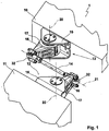
Figur 1- eine perspektivische Ansicht einer Stabilisatorvorrichtung in Anordnung zwischen zwei Wagenkästen eines Schienenfahrzeugs,
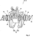
- Figur 2
- eine perspektivische, fliegende Ansicht der Bestandteile eines Befestigungskörpers als Teil der Stabilisatorvorrichtung,
- Figur 3
- eine perspektivische Ansicht eines Drehgelenkes der Befestigungskörper der Stabilisatorvorrichtung mit den Merkmalen der Erfindung,
- Figur 4
- eine Schnittansicht in axialer Richtung des Drehgelenkes gemäß
Figur 3 , - Figur 5a, 5b
- eine Explosionsdarstellung und eine Zusammenbaudarstellung des Koppelelementes der Stabilisatorvorrichtung.
- Figure 1
- 1 shows a perspective view of a stabilizer device arranged between two car bodies of a rail vehicle,
- Figure 2
- 2 shows a perspective, flying view of the components of a fastening body as part of the stabilizer device,
- Figure 3
- 2 shows a perspective view of a swivel joint of the fastening body of the stabilizer device with the features of the invention,
- Figure 4
- a sectional view in the axial direction of the swivel according
Figure 3 , - Figure 5a, 5b
- an exploded view and an assembly view of the coupling element of the stabilizer device.
Die Stabilisatorvorrichtung 1 weist zu ihrer Befestigung einen ersten Befestigungskörper 12 zur Anordnung am ersten Wagenkasten 11 und einen beispielsweise baugleichen zweiten Befestigungskörper 13 zur Anordnung am zweiten Wagenkasten 10 auf. Zwischen den beiden Befestigungskörpern 12 und 13 erstreckt sich ein Koppelelement 14, mit dem die beiden Befestigungskörper 12 und 13 miteinander gelenkig gekoppelt sind. Die Anbindung des Koppelelementes 14 an die Befestigungskörper 12 und 13 erfolgt über Koppelgelenke 32, die als Kugelgelenke ausgeführt sind. Damit können die Wagenkästen 10 und 11 sowohl eine Wankbewegung als auch eine Nickbewegung und eine Knickbewegung zueinander ausführen, wobei auch eine Versatzbewegung der Wagenkästen 10 und 11 möglich ist, ohne dass es zu Verspannungen in der Stabilisatorvorrichtung 1 kommen kann.The
Die Wankbewegungen der Wagenkästen 10 und 11 zueinander und damit deren Relativbewegungen erfolgen in einer Längsachse 21 des Koppelelementes 14, wodurch die eigentliche Stabilisierung der Wagenkästen 10 und 11 zueinander erfolgt, und wobei in gewissen Grenzen auch eine Stabilisierung einer Nickbewegung der Wagenkästen 10, 11 zueinander mit der Stabilisatorvorrichtung 1 erreicht werden kann.The rolling movements of the
Die Befestigungskörper 12 und 13 sind mehrteilig ausgebildet und weisen einen Flanschteil 15 zur Anordnung am jeweiligen Wagenkasten 10, 11 und einen Koppelteil 16 zur Anbindung des Koppelelementes 14 auf. Zwischen dem Flanschteil 15 und dem Koppelteil 16 befindet sich ein Drehgelenk 17. Das jeweilige Drehgelenk 17 der beiden Befestigungskörper 12, 13 weist eine Gelenkachse 20 auf, die mit einem Verlauf quer zum Verlauf der Längsachse 21 des Koppelelementes ausgebildet ist. Insbesondere verlaufen die Gelenkachsen 20 in vertikaler Richtung.The
Der Achsenkörper 23 weist an seinen jeweiligen axialen Endseiten Aufnahmezapfen 28 auf, und die Aufnahmezapfen 28 werden in Aufnahmeöffnungen 27 eingebracht, die in den Gabelschenkeln 15a und 15b ausgebildet sind. Die Aufnahmeöffnungen 27 weisen eine unrunde Kontur auf, und die Aufnahmezapfen 28 sind komplementär zu der unrunden Kontur ebenfalls unrund ausgebildet, sodass bei einem Einsetzen der Aufnahmezapfen 28 in die Aufnahmeöffnungen 27 eine Verdrehung des Achsenkörpers 23 in der Gelenkachse 20 unterbunden ist. Beispielsweise sind die Aufnahmeöffnungen 27 und die Aufnahmezapfen 28 oval oder elliptisch ausgebildet.The
Um den Achsenkörper 23 in Anordnung an den Gabelschenkeln 15a, 15b zu sichern, sind Deckelelemente 29 vorgesehen, die mit Schraubelementen 30 am jeweiligen Gabelschenkel 15a und 15b sowie dem Achsenkörper 23 axial verschraubt werden, wobei ferner Dichtelemente 31 zwischen den Deckelelementen 29 und der Seitenflächen der Gabelschenkel 15a, 15b angeordnet werden.In order to secure the
Zwischen dem Koppelteil 16 und dem Achsenkörper 23 ist das Drehgelenk 17 gebildet, das in der
Das Drehgelenk 17 wird gebildet durch den Hülsenkörper 22 und den Achsenkörper 23, wobei der sich der Achsenkörper 23 durch den Hülsenkörper 22 hindurch erstreckt. Im so gebildeten umlaufenden radialen Spalt zwischen dem Achsenkörper 23 und dem Hülsenkörper 22 ist ein elastischer Körper 19 eingebracht, insbesondere einvulkanisiert, und unter Aufbringung einer Torsionskraft auf den Hülsenkörper 22 kann dieser relativ zum Achsenkörper 23 unter elastischer Verformung des elastischen Körpers 19 um die Gelenkachse 20 verdreht werden.The swivel joint 17 is formed by the
Der elastische Körper 19 bildet ein Dämpfungsmittel 18, und je größer der Verdrehwinkel des Hülsenkörpers 22 relativ zum Achsenkörper 23 in der Gelenkachse 20 ist, desto größer wird die Verdrehkraft, die aufgebracht werden muss, um die Verdrehung weiterzuführen.The
Zur Begrenzung der Verdrehung des Hülsenkörpers 22 auf dem Achsenkörper 23 um die Gelenkachse 20 dienen diametral gegenüberliegende Verdrehbegrenzungen 24. Die Verdrehbegrenzungen 24 weisen Vorsprünge 25 auf, die radial nach innen in den umlaufenden Spalt hineinragen, und die Vorsprünge 25 sind so tief ausgeführt, dass diese in Aussparungen 26 hineinragen, die an komplementärer Stelle zur Anordnung der Vorsprünge 25 im Achsenkörper 23 eingebracht sind, beispielsweise als Längsnuten auf dem Außenumfang. Wird eine Verdrehung des Hülsenkörpers 22 relativ zum Achsenkörper 23 hervorgerufen, so gelangen die Seitenflanken der Vorsprünge 25 bei einem definierten Verdrehwinkel an die Seitenwandung der Aussparungen 26, wodurch ein Festkörperanschlag zwischen Hülsenkörper 22 und Achsenkörper 23 in Umfangsrichtung erzielt wird. Das Maß des Spaltes in Umfangsrichtung zwischen den Vorsprüngen 25 und den Aussparungen 26 definiert die maximale Verdrehbewegung, bevor es zu dem Festkörperanschlag kommt. Durch die diametral gegenüberliegende Anordnung der Verdrehbegrenzungen 24 kann eine Torsionsverspannung zwischen dem Hülsenkörper 22 und dem Achsenkörper 23 ohne die Entstehung von Kippmomenten oder dergleichen erfolgen.To limit the rotation of the
Die
Als wesentlicher Bestandteil weisen die Koppelelemente 14 eine Gewindestange 33 auf, und die Gewindestange 33 weist einen ersten Gewindebereich 34a und einen zweiten Gewindebereich 34b auf. Auf die Gewindebereiche 34a, 34b werden Endelemente 35 aufgeschraubt, wobei mit besonderem Vorteil die Gewindebereiche 34a und 34b jeweils ein Rechtsgewinde und ein Linksgewinde bilden. Werden die Endelemente 35 fixiert, können durch eine Drehung der Gewindestange 33 in einer Drehrichtung beide Gewindebereiche 34a, 34b in die Endelemente 35 eingeschraubt werden. Zur Fixierung der Einschraubtiefe dienen Sicherungsmuttern 37.As an essential component, the
Durch die Gewindebereiche 34a und 34b kann der Abstand zwischen den Gelenkbolzen 36 auch im fertig montierten Zustand der Stabilisatorvorrichtung 1 zwischen den Wagenkästen 10, 11 eingestellt werden, sodass zur Sicherung der eingestellten Länge des Koppelelementes 14 lediglich noch die Sicherungsmuttern 37 mit den Endelementen 35 auf den Gewindebereichen 34a, 34b verspannt werden müssen.Through the threaded
Im Ergebnis ergibt sich durch das aufgeführte Ausführungsbeispiel einer Stabilisatorvorrichtung 1 eine einfache, kostengünstige und robuste Ausführung, um Wankbewegungen zwischen den Wagenkästen 10, 11 eines Schienenfahrzeugs oder beispielsweise auch eines Straßenfahrzeugs, insbesondere Bus, zu dämpfen und/oder zu reduzieren.As a result, the exemplary embodiment of a
Das Drehgelenk 17 kann sehr robust ausgeführt werden und weist keinen Fluiddämpfer auf, über den die Dämpfungswirkung erzielt werden muss. Das Dämpfungsmittel 18 wird durch den robusten elastischen Körper 19 gebildet, der bei einer Verformung hinreichend energiedissipierend wirkt, sodass Schwingungen zwischen den Wagenkästen 10, 11 durch die Stabilisatorvorrichtung 1 vorzugsweise gedämpft bzw. getilgt werden können.The swivel joint 17 can be made very robust and has no fluid damper, via which the damping effect must be achieved. The damping means 18 is formed by the robust
Die Erfindung beschränkt sich in ihrer Ausführung nicht lediglich auf das vorstehend angegebene bevorzugte Ausführungsbeispiel. Vielmehr ist eine Anzahl von Varianten denkbar, welche von der dargestellten Lösung auch bei grundsätzlich anders gearteten Ausführungen Gebrauch macht. Sämtliche aus den Ansprüchen, der Beschreibung oder den Zeichnungen hervorgehenden Merkmale und/oder Vorteile, einschließlich konstruktiver Einzelheiten oder räumlicher Anordnungen, können sowohl für sich als auch in den verschiedensten Kombinationen erfindungswesentlich sein. Beispielsweise können die Flanschteile 15 auch einteilig mit oder als Anformung an den Stirnseiten der Wagenkästen 10, 11 ausgebildet sein, in oder an denen die Drehgelenke 17 aufgenommen sind.The embodiment of the invention is not limited to the preferred exemplary embodiment specified above. Rather, a number of variants are conceivable which make use of the solution shown even in the case of fundamentally different types. All features and / or advantages arising from the claims, the description or the drawings, including constructive Details or spatial arrangements can be essential to the invention both individually and in a wide variety of combinations. For example, the
- 11
- StabilisatorvorrichtungStabilizer device
- 1010th
- WagenkastenCar body
- 1111
- WagenkastenCar body
- 1212th
- BefestigungskörperFastening body
- 1313
- BefestigungskörperFastening body
- 1414
- KoppelelementCoupling element
- 1515
- FlanschteilFlange part
- 15a15a
- GabelschenkelFork leg
- 15b15b
- GabelschenkelFork leg
- 1616
- KoppelteilCoupling part
- 1717th
- DrehgelenkSwivel
- 1818th
- DämpfungsmittelDamping agents
- 1919th
- elastischer Körperelastic body
- 2020th
- GelenkachseHinge axis
- 2121
- LängsachseLongitudinal axis
- 2222
- HülsenkörperSleeve body
- 2323
- AchsenkörperAxle body
- 2424th
- VerdrehbegrenzungLimitation of rotation
- 2525th
- Vorsprunghead Start
- 2626
- AussparungRecess
- 2727
- AufnahmeöffnungReceiving opening
- 2828
- AufnahmezapfenLocating pin
- 2929
- DeckelelementCover element
- 3030th
- SchraubelementScrew element
- 3131
- DichtelementSealing element
- 3232
- KoppelgelenkCoupling joint
- 3333
- GewindestangeThreaded rod
- 34a34a
- erster Gewindebereichfirst thread area
- 34b34b
- zweiter Gewindebereichsecond thread area
- 3535
- EndelementEnd element
- 3636
- GelenkbolzenHinge pin
- 3737
- SicherungsmutterLock nut
Claims (16)
dadurch gekennzeichnet,
dass die Befestigungskörper (12, 13) einen Flanschteil (15) zur Anordnung am Wagenkasten (10, 11) und einen Koppelteil (16) zur Aufnahme des Koppelelementes (14) aufweisen, und wobei der Flanschteil (15) und der Koppelteil (16) mittels eines Drehgelenkes (17) miteinander verbunden sind.Stabilizer device (1) for arrangement between a first car body (10) and a second car body (11) of a vehicle, in particular roll stabilizer for arrangement in the roof area between the car bodies (10, 11) of a rail vehicle, comprising a first fastening body (12) for arrangement on first car body (11) and a second fastening body (13) for arrangement on the second car body (10), further comprising a coupling element (14) with which the two fastening bodies (12, 13) are coupled to one another,
characterized,
that the fastening bodies (12, 13) have a flange part (15) for arrangement on the car body (10, 11) and a coupling part (16) for receiving the coupling element (14), and the flange part (15) and the coupling part (16) are connected to one another by means of a swivel joint (17).
dadurch gekennzeichnet,
dass das Drehgelenk (17) ein Dämpfungsmittel (18) aufweist.Stabilizer device (1) according to claim 1,
characterized,
that the swivel joint (17) has a damping means (18).
dadurch gekennzeichnet,
dass das Dämpfungsmittel (18) wenigstens einen elastischen Körper (19) umfasst.Stabilizer device (1) according to claim 2,
characterized,
that the damping means (18) comprises at least one elastic body (19).
dadurch gekennzeichnet,
dass der elastische Körper (19) einen Gummiwerkstoff und/oder einen Kautschukkörper und/oder ein Elastomer umfasst.Stabilizer device (1) according to claim 3,
characterized,
that the elastic body (19) comprises a rubber material and / or a rubber body and / or an elastomer.
dadurch gekennzeichnet,
dass das Drehgelenk (17) eine Gelenkachse (20) aufweist, die mit einem Verlauf quer zum Verlauf einer Längsachse (21) des Koppelelementes (14) ausgebildet ist.Stabilizer device (1) according to one of the preceding claims,
characterized,
that the swivel joint (17) has an articulation axis (20) which is designed with a course transverse to the course of a longitudinal axis (21) of the coupling element (14).
dass das Koppelelement (14) mittels eins Koppelgelenks (32) beweglich an dem jeweiligen Koppelteil (16) der Befestigungskörper (12, 13) angebunden ist.Stabilizer device (1) according to one of the preceding claims, characterized in that
that the coupling element (14) is movably connected to the respective coupling part (16) of the fastening body (12, 13) by means of a coupling joint (32).
dadurch gekennzeichnet,
dass das Koppelgelenk (32) ein Kugelgelenk aufweist.Stabilizer device (1) according to claim 6,
characterized,
that the coupling joint (32) has a ball joint.
dadurch gekennzeichnet,
dass das Koppelelement (14) in der Länge verstellbar ausgebildet ist.Stabilizer device (1) according to one of the preceding claims,
characterized,
that the coupling element (14) is adjustable in length.
dadurch gekennzeichnet,
dass das Koppelelement (14) eine Gewindestange (33) aufweist, wobei die Gewindestange (33) einen ersten Gewindebereich (34a) mit einem Linksgewinde und einen zweiten, gegenüberliegenden Gewindebereich (34b) mit einem Rechtsgewinde umfasst, auf die Endelemente (35) des Koppelelementes (14) aufgeschraubt sind.Stabilizer device (1) according to claim 8,
characterized,
that the coupling element (14) has a threaded rod (33), the threaded rod (33) comprising a first threaded area (34a) with a left-hand thread and a second, opposite threaded area (34b) with a right-hand thread, onto the end elements (35) of the coupling element (14) are screwed on.
dadurch gekennzeichnet,
dass das Drehgelenk (17) einen Hülsenkörper (22) und einen Achsenkörper (23) aufweist, wobei zwischen dem Hülsenkörper (22) und dem Achsenkörper (23) der das Dämpfungsmittel (18) bildende elastische Körper (19) eingebracht ist.Stabilizer device (1) according to one of the preceding claims,
characterized,
that the swivel joint (17) has a sleeve body (22) and an axle body (23), the elastic body (19) forming the damping means (18) being introduced between the sleeve body (22) and the axle body (23).
dadurch gekennzeichnet,
dass der Hülsenkörper (22) im Koppelteil (16) und der Achsenkörper (23) im Flanschteil (15) jeweils feststehend aufgenommen sind.Stabilizer device (1) according to claim 10,
characterized,
that the sleeve body (22) in the coupling part (16) and the axle body (23) in the flange part (15) are each fixed.
dadurch gekennzeichnet,
dass zwischen dem Hülsenkörper (22) und dem Achsenkörper (23) eine Verdrehbegrenzung (24) eingebracht ist, sodass die gelenkige Verdrehbewegung des Koppelteils (16) zum Flanschteil (15) auf einen vorgebbaren Winkelbereich begrenzt ist.Stabilizer device (1) according to claim 10 or 11,
characterized,
that a twist limiter (24) is introduced between the sleeve body (22) and the axle body (23), so that the articulated twisting movement of the coupling part (16) to the flange part (15) is limited to a predeterminable angular range.
dadurch gekennzeichnet,
dass die Verdrehbegrenzung (24) wenigstens einen am Hülsenkörper (22) ausgebildeten und nach innen in Richtung zum Achsenkörper (23) weisenden Vorsprung (25) aufweist, der in wenigstens eine im Achsenkörper (23) eingebrachte Aussparung (26) hineinragt, wobei die Aussparung (26) in Umfangsrichtung breiter ausgeführt ist als die Breite des Vorsprunges (25).Stabilizer device (1) according to claim 12,
characterized,
that the rotation limiter (24) has at least one projection (25) which is formed on the sleeve body (22) and points inward towards the axle body (23) and which projects into at least one recess (26) made in the axle body (23), the recess (26) is made wider in the circumferential direction than the width of the projection (25).
dadurch gekennzeichnet,
dass der Flanschteil (15) gabelförmig ausgebildet ist und den Achsenkörper (23) zwischen zwei Gabelschenkeln (15a, 15b) des Flanschteils (15) in der Gelenkachse (20) aufnimmt.Stabilizer device (1) according to one of the preceding claims,
characterized,
that the flange part (15) is fork-shaped and receives the axle body (23) between two fork legs (15a, 15b) of the flange part (15) in the hinge axis (20).
dadurch gekennzeichnet,
dass die Gabelschenkel (15a, 15b) zur Aufnahme des Achsenkörpers (23) unrund ausgebildete Aufnahmeöffnungen (27) aufweisen, in die am Achsenkörper (23) ausgebildete Aufnahmezapfen (28) eingesetzt sind, die komplementär zu den unrund ausgebildeten Aufnahmeöffnungen (27) ausgebildet sind, sodass eine Verdrehung des Achsenkörpers (23) um die Gelenkachse (20) unterbunden ist.Stabilizer device (1) according to claim 14,
characterized,
that the fork legs (15a, 15b) for receiving the axle body (23) have non-circular receiving openings (27), into which receiving pins (28) formed on the axle body (23) are inserted, which are complementary to the non-circular receiving openings (27) , so that rotation of the axle body (23) around the joint axis (20) is prevented.
dadurch gekennzeichnet,
dass der wenigstens eine elastische Körper (19) in einen umlaufenden Spalt zwischen dem Hülsenkörper (22) und dem Achsenkörper (23) auf wenigstens einem Umfangsabschnitt einvulkanisiert ist.Stabilizer device (1) according to one of Claims 10 to 15,
characterized,
that the at least one elastic body (19) is vulcanized into a circumferential gap between the sleeve body (22) and the axle body (23) on at least one peripheral section.
Applications Claiming Priority (1)
| Application Number | Priority Date | Filing Date | Title |
|---|---|---|---|
| DE202018105298.5U DE202018105298U1 (en) | 2018-09-17 | 2018-09-17 | Stabilizer device for rail vehicles, in particular roll stabilizers |
Publications (3)
| Publication Number | Publication Date |
|---|---|
| EP3623251A1 true EP3623251A1 (en) | 2020-03-18 |
| EP3623251C0 EP3623251C0 (en) | 2023-09-27 |
| EP3623251B1 EP3623251B1 (en) | 2023-09-27 |
Family
ID=64745319
Family Applications (1)
| Application Number | Title | Priority Date | Filing Date |
|---|---|---|---|
| EP19193998.2A Active EP3623251B1 (en) | 2018-09-17 | 2019-08-28 | Stabilizer device for rail vehicles, especially a roll stabilizer |
Country Status (4)
| Country | Link |
|---|---|
| EP (1) | EP3623251B1 (en) |
| CN (1) | CN110901680B (en) |
| DE (1) | DE202018105298U1 (en) |
| ES (1) | ES2963302T3 (en) |
Families Citing this family (1)
| Publication number | Priority date | Publication date | Assignee | Title |
|---|---|---|---|---|
| CN110435705B (en) * | 2019-08-14 | 2020-12-01 | 株洲中车特种装备科技有限公司 | Single-shaft sightseeing train hinging system |
Citations (4)
| Publication number | Priority date | Publication date | Assignee | Title |
|---|---|---|---|---|
| US1740357A (en) * | 1928-07-24 | 1929-12-17 | Gen Electric | Restraining device |
| NL39938C (en) * | 1934-05-09 | 1937-01-15 | DEVICE FOR DAMPING THE SLINGING MOVEMENTS OF VEHICLES MOVING ON RAILS | |
| DE693928C (en) * | 1938-03-23 | 1940-07-22 | Christoph & Unmack Akt Ges | Device to improve the stability of roofed wagons |
| EP2765050A1 (en) | 2013-02-09 | 2014-08-13 | Hübner GmbH & Co. KG | Device in the roof area of two vehicle sections with a jointed connection for limiting the angle of the vehicle sections relative to each other |
Family Cites Families (12)
| Publication number | Priority date | Publication date | Assignee | Title |
|---|---|---|---|---|
| GB247788A (en) * | 1925-04-04 | 1926-02-25 | Walter Carman White | Improvements in and relating to train pipe couplings |
| DD122174A3 (en) * | 1974-11-11 | 1976-09-20 | ||
| DE4201122A1 (en) * | 1992-01-17 | 1993-07-22 | Duewag Ag | TROLLEY UNIT, ESPECIALLY FOR GOODS TRANSPORT |
| CN2189574Y (en) * | 1994-03-08 | 1995-02-15 | 于修贵 | Combined rigid linklever for mining car |
| CN201296258Y (en) * | 2008-07-29 | 2009-08-26 | 溧阳市振大铁路设备有限公司 | Anti-side-rolling torsion bar device for trains in MU train group |
| CN101612943A (en) * | 2009-06-30 | 2009-12-30 | 中国北车集团大连机车研究所有限公司 | Hinging mechanism for multi-section connection of urban low-floor rail vehicle |
| CN201538329U (en) * | 2009-06-30 | 2010-08-04 | 中国北车集团大连机车研究所有限公司 | Free articulated device for articulation of urban low-floor railway vehicles |
| CN201721457U (en) * | 2010-07-14 | 2011-01-26 | 青岛华轩交通装备科技有限公司 | Light rail traction universal control hinging mechanism |
| DE102014010803A1 (en) * | 2014-07-22 | 2016-01-28 | Man Truck & Bus Ag | Vehicle joint for an articulated vehicle with damping device |
| CN203995516U (en) * | 2014-08-18 | 2014-12-10 | 东风汽车公司 | A kind of length-adjustable hard draw gear |
| CN205601858U (en) * | 2016-05-19 | 2016-09-28 | 虎伯拉铰接系统(上海)有限公司 | Rail car and free hinge system thereof |
| CN107458413A (en) * | 2016-06-02 | 2017-12-12 | 株洲时代新材料科技股份有限公司 | Freely be articulated and connected method and articulated system between a kind of low floor vehicle car body |
-
2018
- 2018-09-17 DE DE202018105298.5U patent/DE202018105298U1/en active Active
-
2019
- 2019-08-28 EP EP19193998.2A patent/EP3623251B1/en active Active
- 2019-08-28 ES ES19193998T patent/ES2963302T3/en active Active
- 2019-09-16 CN CN201910870220.2A patent/CN110901680B/en active Active
Patent Citations (4)
| Publication number | Priority date | Publication date | Assignee | Title |
|---|---|---|---|---|
| US1740357A (en) * | 1928-07-24 | 1929-12-17 | Gen Electric | Restraining device |
| NL39938C (en) * | 1934-05-09 | 1937-01-15 | DEVICE FOR DAMPING THE SLINGING MOVEMENTS OF VEHICLES MOVING ON RAILS | |
| DE693928C (en) * | 1938-03-23 | 1940-07-22 | Christoph & Unmack Akt Ges | Device to improve the stability of roofed wagons |
| EP2765050A1 (en) | 2013-02-09 | 2014-08-13 | Hübner GmbH & Co. KG | Device in the roof area of two vehicle sections with a jointed connection for limiting the angle of the vehicle sections relative to each other |
Also Published As
| Publication number | Publication date |
|---|---|
| EP3623251C0 (en) | 2023-09-27 |
| ES2963302T3 (en) | 2024-03-26 |
| CN110901680A (en) | 2020-03-24 |
| DE202018105298U1 (en) | 2018-12-07 |
| EP3623251B1 (en) | 2023-09-27 |
| CN110901680B (en) | 2021-11-02 |
Similar Documents
| Publication | Publication Date | Title |
|---|---|---|
| EP2243680B1 (en) | Linkage for connecting a coupling rod with a railcar body with a jointed connection | |
| DE102010048210B4 (en) | Vehicle seat with fluid spring | |
| EP3042098B1 (en) | Holding element for a spring | |
| DE3346665A1 (en) | ELASTIC BEARING WITH FORCED GUIDE | |
| EP2414180B1 (en) | Elastomer articulation | |
| EP2391517B1 (en) | Transverse control arm - bushing arrangement of a motor vehicle suspension | |
| EP2736732B1 (en) | Axle adjustment for axles of utility vehicles | |
| DE102010021481B3 (en) | Vehicle seat, particularly commercial vehicle seat, has bearing bush with axial bush opening, which is arranged on axis or tubular component enclosing axis | |
| DE19805810A1 (en) | Element connecting torsion stabiliser to component of vehicle's wheel suspension | |
| DE3629068C2 (en) | ||
| DE2215330A1 (en) | ELASTIC JOINT, IN PARTICULAR FOR STEERING RODS OF MOTOR VEHICLES | |
| EP3623251B1 (en) | Stabilizer device for rail vehicles, especially a roll stabilizer | |
| EP1806517A1 (en) | Metal elastomer pivot bearing, particularly central joint of a triangular suspension arm for connecting an axle body with a vehicle body | |
| WO2017121558A1 (en) | Length-adjustable two-point linkage, in particular for a steering system or a chassis of a utility vehicle | |
| DE102011052747A1 (en) | Clamping sleeve for workpiece clamping apparatus, has cylindrical structures which are arranged centrally between adjacent slots formed in axial direction of main portion, and parallely aligned with each other | |
| DE19748117C2 (en) | ball pin | |
| DE102017214235B3 (en) | coupling device | |
| DE102012013568A1 (en) | connecting device | |
| DE202011051001U1 (en) | Clamping element for a clamping device | |
| DE3138534A1 (en) | Device for the elastic suspension of a strut, support or the like | |
| EP3554918B1 (en) | Attachment for articulated connection of a coupling rod to a carriage body | |
| EP1956252B1 (en) | Longitudinal traverse unit for drive trains | |
| DE102014203242A1 (en) | Fahrwerksaktuatorvorrichtung, in particular roll stabilizer, for a motor vehicle | |
| DE202019107121U1 (en) | Trailing link axle for vehicle trailers | |
| DE102017206937B4 (en) | System for securing a peg |
Legal Events
| Date | Code | Title | Description |
|---|---|---|---|
| PUAI | Public reference made under article 153(3) epc to a published international application that has entered the european phase |
Free format text: ORIGINAL CODE: 0009012 |
|
| STAA | Information on the status of an ep patent application or granted ep patent |
Free format text: STATUS: THE APPLICATION HAS BEEN PUBLISHED |
|
| AK | Designated contracting states |
Kind code of ref document: A1 Designated state(s): AL AT BE BG CH CY CZ DE DK EE ES FI FR GB GR HR HU IE IS IT LI LT LU LV MC MK MT NL NO PL PT RO RS SE SI SK SM TR |
|
| AX | Request for extension of the european patent |
Extension state: BA ME |
|
| STAA | Information on the status of an ep patent application or granted ep patent |
Free format text: STATUS: REQUEST FOR EXAMINATION WAS MADE |
|
| 17P | Request for examination filed |
Effective date: 20201102 |
|
| RBV | Designated contracting states (corrected) |
Designated state(s): AL AT BE BG CH CY CZ DE DK EE ES FI FR GB GR HR HU IE IS IT LI LT LU LV MC MK MT NL NO PL PT RO RS SE SI SK SM TR |
|
| STAA | Information on the status of an ep patent application or granted ep patent |
Free format text: STATUS: EXAMINATION IS IN PROGRESS |
|
| 17Q | First examination report despatched |
Effective date: 20220218 |
|
| GRAP | Despatch of communication of intention to grant a patent |
Free format text: ORIGINAL CODE: EPIDOSNIGR1 |
|
| STAA | Information on the status of an ep patent application or granted ep patent |
Free format text: STATUS: GRANT OF PATENT IS INTENDED |
|
| INTG | Intention to grant announced |
Effective date: 20230330 |
|
| GRAS | Grant fee paid |
Free format text: ORIGINAL CODE: EPIDOSNIGR3 |
|
| GRAA | (expected) grant |
Free format text: ORIGINAL CODE: 0009210 |
|
| STAA | Information on the status of an ep patent application or granted ep patent |
Free format text: STATUS: THE PATENT HAS BEEN GRANTED |
|
| AK | Designated contracting states |
Kind code of ref document: B1 Designated state(s): AL AT BE BG CH CY CZ DE DK EE ES FI FR GB GR HR HU IE IS IT LI LT LU LV MC MK MT NL NO PL PT RO RS SE SI SK SM TR |
|
| REG | Reference to a national code |
Ref country code: GB Ref legal event code: FG4D Free format text: NOT ENGLISH |
|
| REG | Reference to a national code |
Ref country code: CH Ref legal event code: EP |
|
| P01 | Opt-out of the competence of the unified patent court (upc) registered |
Effective date: 20230911 |
|
| REG | Reference to a national code |
Ref country code: DE Ref legal event code: R096 Ref document number: 502019009476 Country of ref document: DE |
|
| REG | Reference to a national code |
Ref country code: IE Ref legal event code: FG4D Free format text: LANGUAGE OF EP DOCUMENT: GERMAN |
|
| U01 | Request for unitary effect filed |
Effective date: 20231011 |
|
| P04 | Withdrawal of opt-out of the competence of the unified patent court (upc) registered |
Effective date: 20231016 |
|
| U07 | Unitary effect registered |
Designated state(s): AT BE BG DE DK EE FI FR IT LT LU LV MT NL PT SE SI Effective date: 20231019 |
|
| PG25 | Lapsed in a contracting state [announced via postgrant information from national office to epo] |
Ref country code: GR Free format text: LAPSE BECAUSE OF FAILURE TO SUBMIT A TRANSLATION OF THE DESCRIPTION OR TO PAY THE FEE WITHIN THE PRESCRIBED TIME-LIMIT Effective date: 20231228 |
|
| PG25 | Lapsed in a contracting state [announced via postgrant information from national office to epo] |
Ref country code: RS Free format text: LAPSE BECAUSE OF FAILURE TO SUBMIT A TRANSLATION OF THE DESCRIPTION OR TO PAY THE FEE WITHIN THE PRESCRIBED TIME-LIMIT Effective date: 20230927 Ref country code: NO Free format text: LAPSE BECAUSE OF FAILURE TO SUBMIT A TRANSLATION OF THE DESCRIPTION OR TO PAY THE FEE WITHIN THE PRESCRIBED TIME-LIMIT Effective date: 20231227 Ref country code: HR Free format text: LAPSE BECAUSE OF FAILURE TO SUBMIT A TRANSLATION OF THE DESCRIPTION OR TO PAY THE FEE WITHIN THE PRESCRIBED TIME-LIMIT Effective date: 20230927 Ref country code: GR Free format text: LAPSE BECAUSE OF FAILURE TO SUBMIT A TRANSLATION OF THE DESCRIPTION OR TO PAY THE FEE WITHIN THE PRESCRIBED TIME-LIMIT Effective date: 20231228 |
|
| REG | Reference to a national code |
Ref country code: ES Ref legal event code: FG2A Ref document number: 2963302 Country of ref document: ES Kind code of ref document: T3 Effective date: 20240326 |
|
| PG25 | Lapsed in a contracting state [announced via postgrant information from national office to epo] |
Ref country code: IS Free format text: LAPSE BECAUSE OF FAILURE TO SUBMIT A TRANSLATION OF THE DESCRIPTION OR TO PAY THE FEE WITHIN THE PRESCRIBED TIME-LIMIT Effective date: 20240127 |
|
| PG25 | Lapsed in a contracting state [announced via postgrant information from national office to epo] |
Ref country code: SM Free format text: LAPSE BECAUSE OF FAILURE TO SUBMIT A TRANSLATION OF THE DESCRIPTION OR TO PAY THE FEE WITHIN THE PRESCRIBED TIME-LIMIT Effective date: 20230927 Ref country code: RO Free format text: LAPSE BECAUSE OF FAILURE TO SUBMIT A TRANSLATION OF THE DESCRIPTION OR TO PAY THE FEE WITHIN THE PRESCRIBED TIME-LIMIT Effective date: 20230927 Ref country code: IS Free format text: LAPSE BECAUSE OF FAILURE TO SUBMIT A TRANSLATION OF THE DESCRIPTION OR TO PAY THE FEE WITHIN THE PRESCRIBED TIME-LIMIT Effective date: 20240127 Ref country code: CZ Free format text: LAPSE BECAUSE OF FAILURE TO SUBMIT A TRANSLATION OF THE DESCRIPTION OR TO PAY THE FEE WITHIN THE PRESCRIBED TIME-LIMIT Effective date: 20230927 Ref country code: SK Free format text: LAPSE BECAUSE OF FAILURE TO SUBMIT A TRANSLATION OF THE DESCRIPTION OR TO PAY THE FEE WITHIN THE PRESCRIBED TIME-LIMIT Effective date: 20230927 |