EP3623250A1 - Derailment detection device and associated railway vehicle and method - Google Patents
Derailment detection device and associated railway vehicle and method Download PDFInfo
- Publication number
- EP3623250A1 EP3623250A1 EP19196946.8A EP19196946A EP3623250A1 EP 3623250 A1 EP3623250 A1 EP 3623250A1 EP 19196946 A EP19196946 A EP 19196946A EP 3623250 A1 EP3623250 A1 EP 3623250A1
- Authority
- EP
- European Patent Office
- Prior art keywords
- detection device
- derailment detection
- railway vehicle
- magnetic force
- derailment
- Prior art date
- Legal status (The legal status is an assumption and is not a legal conclusion. Google has not performed a legal analysis and makes no representation as to the accuracy of the status listed.)
- Granted
Links
- 238000001514 detection method Methods 0.000 title claims abstract description 65
- 238000000034 method Methods 0.000 title claims description 9
- 230000005291 magnetic effect Effects 0.000 claims abstract description 91
- 238000012545 processing Methods 0.000 claims abstract description 11
- XAGFODPZIPBFFR-UHFFFAOYSA-N aluminium Chemical compound [Al] XAGFODPZIPBFFR-UHFFFAOYSA-N 0.000 claims description 6
- 229910052782 aluminium Inorganic materials 0.000 claims description 6
- 238000005259 measurement Methods 0.000 description 5
- 239000000463 material Substances 0.000 description 4
- 230000001681 protective effect Effects 0.000 description 4
- 230000003014 reinforcing effect Effects 0.000 description 4
- 238000005096 rolling process Methods 0.000 description 3
- XEEYBQQBJWHFJM-UHFFFAOYSA-N Iron Chemical compound [Fe] XEEYBQQBJWHFJM-UHFFFAOYSA-N 0.000 description 2
- 229910000831 Steel Inorganic materials 0.000 description 2
- 230000007423 decrease Effects 0.000 description 2
- 239000003302 ferromagnetic material Substances 0.000 description 2
- 230000001939 inductive effect Effects 0.000 description 2
- 239000010959 steel Substances 0.000 description 2
- 229910052779 Neodymium Inorganic materials 0.000 description 1
- 230000002547 anomalous effect Effects 0.000 description 1
- 238000010276 construction Methods 0.000 description 1
- 230000000977 initiatory effect Effects 0.000 description 1
- 229910052742 iron Inorganic materials 0.000 description 1
- 238000012423 maintenance Methods 0.000 description 1
- 238000012544 monitoring process Methods 0.000 description 1
- QEFYFXOXNSNQGX-UHFFFAOYSA-N neodymium atom Chemical compound [Nd] QEFYFXOXNSNQGX-UHFFFAOYSA-N 0.000 description 1
- 229910001172 neodymium magnet Inorganic materials 0.000 description 1
- 230000008520 organization Effects 0.000 description 1
- 230000002085 persistent effect Effects 0.000 description 1
- 230000008093 supporting effect Effects 0.000 description 1
Images


Classifications
-
- B—PERFORMING OPERATIONS; TRANSPORTING
- B61—RAILWAYS
- B61F—RAIL VEHICLE SUSPENSIONS, e.g. UNDERFRAMES, BOGIES OR ARRANGEMENTS OF WHEEL AXLES; RAIL VEHICLES FOR USE ON TRACKS OF DIFFERENT WIDTH; PREVENTING DERAILING OF RAIL VEHICLES; WHEEL GUARDS, OBSTRUCTION REMOVERS OR THE LIKE FOR RAIL VEHICLES
- B61F9/00—Rail vehicles characterised by means for preventing derailing, e.g. by use of guide wheels
- B61F9/005—Rail vehicles characterised by means for preventing derailing, e.g. by use of guide wheels by use of non-mechanical means, e.g. acoustic or electromagnetic devices
-
- B—PERFORMING OPERATIONS; TRANSPORTING
- B60—VEHICLES IN GENERAL
- B60T—VEHICLE BRAKE CONTROL SYSTEMS OR PARTS THEREOF; BRAKE CONTROL SYSTEMS OR PARTS THEREOF, IN GENERAL; ARRANGEMENT OF BRAKING ELEMENTS ON VEHICLES IN GENERAL; PORTABLE DEVICES FOR PREVENTING UNWANTED MOVEMENT OF VEHICLES; VEHICLE MODIFICATIONS TO FACILITATE COOLING OF BRAKES
- B60T7/00—Brake-action initiating means
- B60T7/12—Brake-action initiating means for automatic initiation; for initiation not subject to will of driver or passenger
- B60T7/124—Brakes for railway vehicles coming into operation in case of accident, derailment or damage of rolling stock or superstructure
-
- B—PERFORMING OPERATIONS; TRANSPORTING
- B61—RAILWAYS
- B61K—AUXILIARY EQUIPMENT SPECIALLY ADAPTED FOR RAILWAYS, NOT OTHERWISE PROVIDED FOR
- B61K9/00—Railway vehicle profile gauges; Detecting or indicating overheating of components; Apparatus on locomotives or cars to indicate bad track sections; General design of track recording vehicles
- B61K9/12—Measuring or surveying wheel-rims
-
- B—PERFORMING OPERATIONS; TRANSPORTING
- B61—RAILWAYS
- B61L—GUIDING RAILWAY TRAFFIC; ENSURING THE SAFETY OF RAILWAY TRAFFIC
- B61L15/00—Indicators provided on the vehicle or train for signalling purposes
- B61L15/0081—On-board diagnosis or maintenance
Definitions
- the present invention concerns a derailment detection device configured to be provided onboard a railway vehicle to move on rails of a railway track.
- EP 1 422 119 A1 discloses a derailment detection device comprising an inductive sensor and a method comprising monitoring the relative spacing between the device and the track rail and initiating an emergency brake when this spacing is above or below predefined thresholds.
- this derailment detection device is expensive and heavy due to the use of an inductive sensor.
- One of the aims of the invention is therefore to provide a derailment detection device which guarantees the same level of safety while being less expensive and less heavy.
- the invention proposes a derailment detection device wherein the derailment detection device comprises:
- the derailment detection device comprises one or several of the optional following features, taken individually or according to any technical feasible combination:
- the invention also concerns a railway vehicle configured to move on rails of a railway track, the railway vehicle comprising at least one derailment detection device as defined above.
- the railway vehicle according to the invention comprises advantageously at least one bogie, the railway vehicle comprising, for each bogie, two derailment detection devices fixed to the bogie arranged for being each disposed in front of a respective rail among the rails of the railway track.
- the invention further concerns a method of detecting a derailment of a railway vehicle as defined above, comprising the following steps:
- the railway vehicle 10 represented in figure 1 comprises at least one train carriage 12.
- Each train carriage 12 being associated with at least one bogie 14 supporting the train carriage 12.
- Each train carriage 12 comprises at least one inner compartment configured to receive passengers (passenger compartment) or freight (freight compartment).
- Each bogie 14 is located, for example, at one extremity of the associated train carriage 12 and supports two adjacent train carriages 12 when the railway vehicle 10 comprises several train carriages 12, as shown in figure 1 . Such a bogie 14 is said to be "common" to the two adjacent train carriages 12.
- each train carriage 12 is supported by two bogies 14 at each of its extremities.
- the bogie 14 comprises at least one pair of wheel 16, here two pairs of wheels 16, the two wheels 16 of each pair wheels 16 being coaxial.
- the two wheels 16 of each pair of wheels 16 are for example connected by an axle 18 which is coaxial with the two wheels 16.
- the wheels 16 are mounted mobile in rotation on the bogie 14.
- the wheels 16 are configured to roll on rails 20 of a railway track 22 and enable the railway vehicle 10 to move on the rails 20 with being guided along the rails 20, as visible in figure 2 .
- Each rail 20 is composed of a ferromagnetic material as, for example, iron or steel.
- Each axle 18 is here mounted in rotation about its axis on the bogie 14 via two axle boxes 24 disposed in an adjacent way to each extremity of the axle 18.
- the railway vehicle 10 further comprises at least one derailment detection device 26.
- Each derailment detection device 26 is fixed to the bogie 14, advantageously to one of the axle boxes 24 and is disposed faced to one of the two rails 20, as shown in figure 2 .
- the railway vehicle 10 comprises, for each bogie 14, two derailment detection devices 26 fixed to the bogie 14 and arranged for being each disposed faced to a respective rail 20 among the rails 20 of the railway track 22.
- each derailment detection device 26 is associated to a distinct pair of wheels and to a distinct rail 20.
- the two derailment detection devices 26 are thus arranged diagonally opposite with reference to imaginary rectangle defined by the wheels 16 of the bogie 14.
- the two derailment detection devices 26 can thus be substantially identical such that there is no need to adapt the derailment detection devices 26 for each side of the bogie 14.
- derailment detection devices 26 are substantially identical and only one derailment detection devices 26 will now be described with reference to figure 2 to 5 .
- the derailment detection device 26 comprises at least one magnetic assembly 28, a load cell 30 and an electronic processing module 32.
- the derailment detection device 26 further comprises a housing 34 and a fixing structure 36.
- the magnetic assembly 28 comprises at least one magnet 37.
- magnetic assembly 28 comprises three magnets 37.
- Each magnetic assembly 28 is configured to be disposed faced to one of the rails 20.
- Each magnet 37 is advantageously a permanent magnet.
- a permanent magnet is made of a material that is magnetized and creates its own persistent magnetic field.
- Each magnet 37 is advantageously a neodymium magnet.
- the use of neodymium enables the magnet 37 to be strongly magnetized without being too heavy and/or voluminous.
- each magnet 37 has a remanence higher than 1.0 Tesla.
- Each magnet 37 has a weight inferior to 0.5 kg, in particular comprised between 0.3 kg and 0.7 kg.
- Each magnet 37 has for example a parallelepiped shape.
- Each magnet 37 preferably defines an intern volume inferior to 62.5 cm 3 , in particular comprised between 50 cm 3 and 100 cm 3 .
- each magnet 37 is an electromagnet.
- An electromagnet is a magnet in which the magnetic field is produced by an electric current.
- the magnetic assembly 28 is disposed in the housing 34.
- the housing 34 is configured to partially magnetically isolate the magnetic assembly 28 from the outside of the housing 34.
- the housing 34 is configured to isolate the magnetic assembly 28 in all the directions except towards the associated rail 20, here downwardly.
- the housing 34 is made of aluminum.
- Aluminum is a material that is non-magnetic.
- the magnetic assembly 28 comprising magnets 37 which are magnetized and the rail 20 being composed of a ferromagnetic material, a magnetic force F is generated between the rail 20 and the magnetic assembly 28.
- the load cell 30 is configured to measure the magnetic force F between the rail 20 and the magnetic assembly 28.
- the magnetic assembly 28 is fixed to the bogie 14 via the load cell 30.
- the load cell 30 can measure the attractive force exerted between the magnetic assembly 28 and the associated rail 20
- the magnetic force F applied by the rail 20 on the magnetic assembly 28 is represented in the figure 2 .
- the magnetic force F is here an attractive force.
- the intensity of the magnetic force F between the magnetic assembly 28 and the corresponding rail 20 is a function of the distance between the magnetic assembly 28 and this rail 20.
- the intensity of the magnetic force F diminishes when the distance between the rail 20 and the magnetic assembly 28 increases.
- the intensity of the magnetic force F between the magnetic assembly 28 comprising the three magnets 37 of figure 4 and the rail 20, when the railway vehicle 10 is located on the rails 20, is approximately 600 N.
- the load cell 30 is for example a transducer configured to create an electrical signal whose magnitude is directly proportional to the magnetic force F and to determine a corresponding measured magnetic force Fm.
- the load cell 30 comprises a strain gauge 38 extending along a horizontal axis parallel to the rail 20 and a measurement module 39.
- One extremity of the strain gauge 38 is fixed to the bogie 14 via the fixing structure 36 and the other extremity is fixed to the magnetic assembly 28.
- the strain gauge 38 is configured to be deformed when the magnetic assembly 28 is moving relatively to the bogie 14, in particular when the magnetic assembly 28 is attracted by the rail 20 due to the magnetic force F.
- the deformation of the strain gauge 38 changes its electrical resistance, by an amount that is proportional to the magnetic force F.
- the measurement module 39 is configured to detect the electrical resistance change of the strain gauge 38 and to determine the corresponding measured magnetic force Fm.
- the measurement module 39 is configured to emit the value of the measured magnetic force Fm to the processing module 32.
- the load cell 30 is advantageously received in a protective box (not shown).
- the processing module 32 is configured to compare the measured magnetic force Fm to a predetermined threshold value Ft and to emit an alert signal S when the measured magnetic force Fm is lower than the threshold value Ft.
- the magnetic assembly 28 of the derailment detection device 26 is no more located faced to the associated rail 20 and the magnetic force F between the magnetic assembly 28 and the rail 20 decreases.
- the threshold value Ft is therefore determined to be inferior to the measured magnetic force Fm in normal conditions when the railway vehicle 10 rolls on the rails 20.
- the threshold value Ft is approximately equal to zero, notably inferior to 50 N.
- the alert signal S is advantageously received by an emergency break module 40 configured to trigger an emergency braking when receiving the alert signal S.
- the emergency brake module 40 is for example part of the control system of the railway vehicle 10 known as Train Control & Management System (TCMS).
- TCMS Train Control & Management System
- the fixing structure 36 of the derailment detection device 24 is configured to rigidly connect the load cell 30 to the axle box 24.
- the fixing structure 36 is configured for allowing adjustment of the position of the magnetic assembly 28 with respect to the corresponding rail 20, for example in one adjustment position among a plurality of discrete adjustment positions or configuration, or alternatively in an infinity of positions or configuration between two extreme positions or configurations.
- the fixing structure 36 comprises two brackets 42, 44.
- Each bracket 42, 44 is advantageously made of steel.
- each bracket 42, 44 has a L-shape.
- Each bracket 42, 44 comprises two branches, respectively 46, 48 and 50, 52, defining the L shaped of the bracket 42, 44.
- the first bracket 42 is fixed to the axle box 24.
- the branches 46, 48 of the first bracket 42 extend along respective vertical plans, the two vertical plans being perpendicular one to the other.
- the first branch 46 is advantageously fixed to the axle box 24 by four bolts 54.
- the four bolts 54 form the tops of an imaginary rectangle.
- the second branch 48 is advantageously fixed to the second bracket 44 by advantageously four bolts 56.
- the four bolts 56 form the tops of an imaginary rectangle.
- the second branch 48 is provided with a plurality of holes 58 through which the bolts 56 extend.
- the holes 58 are configured to define a plurality of fixing configurations between the two brackets 42, 44 in order to adjust the position of the derailment detection device 26, e.g. as a function of the wear of the wheels 16.
- the holes 58 define eight distinct discrete configurations to adjust the position of the derailment detection device 26, e.g. by increment of 5 mm in height.
- the first bracket 42 optionally comprises a first corner reinforcing piece 60 extending along a horizontal plan.
- the first corner reinforcing piece 60 is fixed to the two branches 46, 48 of the first bracket 42 to prevent deformation of the first bracket 42.
- the two branches 50, 52 of the second bracket 44 extend along respective plans, the two plans being perpendicular to each other.
- the first branch 50 extends along a vertical plan and the second branch 52 extends along a horizontal plan.
- the second part 48 of the first bracket 42 is fixed to the first branch 50 of the second bracket 44 by the four bolts 56.
- the first branch 50 of the second bracket 44 defines four holes 62 through which the bolts 56 extend.
- the holes 62 are for example oblong holes.
- the load cell 30 is fixed to the second part 48 of the second bracket 44.
- the second bracket 44 optionally comprises a second corner reinforcing piece 64.
- the second corner reinforcing piece 64 is fixed to the two branches 50, 52 of the second bracket 44 and prevents deformation of the second bracket 44.
- the second bracket 44 optionally comprises a protective screen 66.
- the protective screen 66 protrudes vertically from the extremity of the second branch 52 opposite to the wheel 16.
- the protective screen 66 protects the magnetic assembly 28 from external elements which would eventually hit the magnetic assembly 28 when the railway vehicle 10 is rolling.
- the railway vehicle 10 is moving on the rails 20 of the railway track 22.
- each wheel 16 is rolling on the associated rail 20.
- Each derailment detection device 26 is disposed faced to one of the rails 20.
- the magnetic assembly 28 of each derailment detection device 26 is disposed in register of one of the rails 20.
- each bogie 14 two derailment detection devices 26 are disposed faced to a respective one of the rails 20.
- each axle 18 is associated to one of the two derailment detection devices 26.
- the measurement module 39 detects the electrical resistance change of the strain gauge 38 and determines the corresponding measured magnetic force Fm.
- the load cell 30 measure the magnetic force F applied between the rail 20 and the magnetic assembly 28 by determining the measured magnetic force Fm.
- the measurement module 39 emits the value of the measured magnetic force Fm to the processing module 32.
- the processing module 32 compares the measured magnetic force Fm to the predetermined threshold value Ft.
- the processing module 32 is passive.
- the wheel 16 and the associated axle 18 are no more in stable engagement with the rails 20.
- the derailment detection device 26 associated to the problematic axle 18 is then no more disposed faced to the corresponding rail 20.
- the magnetic force F between the magnetic assembly 28 and the rail 20 decreases significantly.
- the measure magnetic force Fm is then lower than the threshold value Ft.
- the processing module 32 When the processing module 32 detects that the measured magnetic force Fm is lower than the threshold value Ft, the processing module 32 emits an alert signal S.
- the alert signal S is received by the emergency brake module 40 which triggers an emergency braking.
- the railway vehicle 10 is thus stopped very quickly before an accident occurs such as a total derailment, in which several wheels 16 are completely out of engagement with the railway track 22 and which can lead to material damage and bodily harm if the railway vehicle 10 overturns.
- the derailment detection device 26 guarantees therefore a great level of safety for the railway vehicle 10.
- the device 26 is less expensive and lighter than the derailment detection devices disclosed in the state of the art.
- the derailment detection device 26 is easily installed on every type of railway vehicle 10 and the fixation of the derailment detection device 26 to the axle box 24 is adapted to the wheels 16 wear thanks to the different configurations of the fixing holes 58.
- the maintenance of the device 26 is easily done as the derailment detection device 26 is directly accessible to an operator.
- a second derailment detection device 126 according to the invention is represented in figures 6 to 8 .
- the second derailment detection device 126 differs from the first derailment detection device 26 in that the fixing structure 36 of the second device 126 comprises a main bracket 68 and two auxiliary brackets 70.
- the main bracket 68 and the two auxiliary brackets 70 are e.g. made of aluminum.
- the use of aluminum enables to obtain a device 126 lighter than the first device 26.
- the main bracket 68 is rigidly fixed to the axle box 24 via the two auxiliary brackets 70, e.g. by bolts 72 extending through the auxiliary brackets 70. As illustrated four bolts 72 are provided and each auxiliary bracket 70 is passed through by two of the bolts 72.
- Each auxiliary bracket 70 extends along a horizontal axis parallel to the rail 20.
- the main bracket 78 comprises three segments 74, 76, 78, a first segment 74 rigidly fixed to the two auxiliary brackets 70, a second segment 76 extending between the first segment 74 and the third segment 78.
- the second segment 76 is e.g. a ramp sloping in direction of the rail 20.
- the third segment 78 defines for example an inner volume 80.
- the load cell 30 is disposed in the inner volume 80.
- the strain gauge 38 of the load cell 30 is disposed vertically.
- the magnetic assembly 28 is supported vertically by the strain gauge 38. As a consequence, when the magnetic assembly 28 is attracted by the rail 20, the strain gauge 38 is deformed in extension along a vertical axis.
- the load cell 30 is fixed to the third segment 78 by an adjustment device 82 configured to adjust the vertical distance between the magnetic assembly 28 and the rail 20, e.g. as a function of the wear of the associated wheel 16.
- the magnetic assembly 28 comprises for example two magnets 37.
- the method of detecting a derailment of a railway vehicle 10 comprising the second device 126 is identical to the method described above for the first derailment detection device 26 and will therefore not be described again.
- the second derailment detection device 126 guarantees therefore the same level of safety for the railway vehicle 10 as the first derailment detection device 26 while being possibly even lighter.
Landscapes
- Engineering & Computer Science (AREA)
- Mechanical Engineering (AREA)
- Physics & Mathematics (AREA)
- Acoustics & Sound (AREA)
- Electromagnetism (AREA)
- Health & Medical Sciences (AREA)
- Biomedical Technology (AREA)
- General Health & Medical Sciences (AREA)
- Transportation (AREA)
- Electric Propulsion And Braking For Vehicles (AREA)
Abstract
- a magnetic assembly comprising at least one magnet and configured to be disposed faced to one of the rails (20) ;
- a sensor (30) configured to measure a magnetic force (F) between the rail (20) and the magnetic assembly ; and
- an electronic processing module configured to compare the measured magnetic force to a predetermined threshold value and to emit an alert signal when the measured magnetic force is lower than the threshold value.
Description
- The present invention concerns a derailment detection device configured to be provided onboard a railway vehicle to move on rails of a railway track.
- By "derailment", it is understood any situation where at least one of the wheels of the railway vehicle is no longer in stable engagement with the corresponding rail.
- This includes total derailment, in which the wheel is completely out of engagement with the rail, as well as partial derailment, in which the wheel, while still in contact with the rail, is in an anomalous position with respect to the rail which can lead to total derailment.
- The derailment of a railway vehicle can cause serious material damage and even bodily harm for passengers and must therefore be quickly detected.
- However, a derailment at the tail of a railway vehicle may not always be readily apparent at the head of the railway vehicle, where the driver is usually located. For this reason, significant damages may be caused already before the driver even notices derailment and takes measures, such as stopping the vehicle.
- For this reason a number of derailment detection devices and methods have been proposed for assisting the driver.
-
EP 1 422 119 A1 discloses a derailment detection device comprising an inductive sensor and a method comprising monitoring the relative spacing between the device and the track rail and initiating an emergency brake when this spacing is above or below predefined thresholds. - Nevertheless, this derailment detection device is expensive and heavy due to the use of an inductive sensor.
- One of the aims of the invention is therefore to provide a derailment detection device which guarantees the same level of safety while being less expensive and less heavy.
- To this aim, the invention proposes a derailment detection device wherein the derailment detection device comprises:
- a magnetic assembly comprising at least one magnet and configured to be disposed faced to one of the rails ;
- a sensor configured to measure a magnetic force between the rail and the magnetic assembly; and
- an electronic processing module configured to compare the measured magnetic force to a predetermined threshold value and to emit an alert signal when the measured magnetic force is lower than the threshold value.
- In specific embodiments, the derailment detection device comprises one or several of the optional following features, taken individually or according to any technical feasible combination:
- the at least one magnet is a permanent magnet;
- the at least one magnet has a remanence higher than 1.0 Tesla ;
- the sensor is a load cell ;
- the derailment detection device comprises a housing, the magnetic assembly being disposed in the housing, the housing being configured to partially magnetically isolate the magnetic assembly from the outside of the housing ;
- the housing is made of aluminum ;
- the derailment detection device is configured to be fixedly attached on an axle box of the railway vehicle.
- The invention also concerns a railway vehicle configured to move on rails of a railway track, the railway vehicle comprising at least one derailment detection device as defined above.
- The railway vehicle according to the invention comprises advantageously at least one bogie, the railway vehicle comprising, for each bogie, two derailment detection devices fixed to the bogie arranged for being each disposed in front of a respective rail among the rails of the railway track.
- The invention further concerns a method of detecting a derailment of a railway vehicle as defined above, comprising the following steps:
- measuring the magnetic force applied between the rail and the magnetic assembly;
- comparing the measured magnetic force to a predetermined threshold value; and
- emitting an alert signal when the measured magnetic force is lower than the threshold value.
- The invention will be better understood upon reading of the following description, given solely as a non-limiting example, and made in reference to the appended drawings, in which:
-
figure 1 is a bottom view of a railway vehicle according to the invention ; -
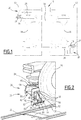
figure 2 is a perspective view of a derailment detection device mounted on a railway vehicle ; -
figure 3 is another perspective view of the derailment detection device offigure 2 ; -
figure 4 is a bottom view of the derailment detection device offigure 2 ; -
figure 5 is an organization chart of the derailment detection device offigure 2 ; -
figure 6 is a perspective view of another derailment detection device mounted on a railway vehicle ; -
figure 7 is a perspective view of a load cell of the derailment detection device offigure 6 ; and -
figure 8 is a bottom view of the derailment detection device offigure 6 . - The terms "vertical" and "horizontal" are generally understood in relation to the usual directions of a railway vehicle rolling on horizontal rails.
- The
railway vehicle 10 represented infigure 1 comprises at least onetrain carriage 12. - Each
train carriage 12 being associated with at least onebogie 14 supporting thetrain carriage 12. - Each
train carriage 12 comprises at least one inner compartment configured to receive passengers (passenger compartment) or freight (freight compartment). - Each
bogie 14 is located, for example, at one extremity of the associatedtrain carriage 12 and supports twoadjacent train carriages 12 when therailway vehicle 10 comprisesseveral train carriages 12, as shown infigure 1 . Such abogie 14 is said to be "common" to the twoadjacent train carriages 12. - According to a conventional construction method, each
train carriage 12 is supported by twobogies 14 at each of its extremities. - The
bogie 14 comprises at least one pair ofwheel 16, here two pairs ofwheels 16, the twowheels 16 of eachpair wheels 16 being coaxial. - The two
wheels 16 of each pair ofwheels 16 are for example connected by anaxle 18 which is coaxial with the twowheels 16. - The
wheels 16 are mounted mobile in rotation on thebogie 14. Thewheels 16 are configured to roll onrails 20 of arailway track 22 and enable therailway vehicle 10 to move on therails 20 with being guided along therails 20, as visible infigure 2 . - Each
rail 20 is composed of a ferromagnetic material as, for example, iron or steel. - Each
axle 18 is here mounted in rotation about its axis on thebogie 14 via twoaxle boxes 24 disposed in an adjacent way to each extremity of theaxle 18. - The
railway vehicle 10 further comprises at least onederailment detection device 26. - Each
derailment detection device 26 is fixed to thebogie 14, advantageously to one of theaxle boxes 24 and is disposed faced to one of the tworails 20, as shown infigure 2 . - Advantageously, the
railway vehicle 10 comprises, for eachbogie 14, twoderailment detection devices 26 fixed to thebogie 14 and arranged for being each disposed faced to arespective rail 20 among therails 20 of therailway track 22. - As shown in
figure 1 , for eachbogie 14, eachderailment detection device 26 is associated to a distinct pair of wheels and to adistinct rail 20. The twoderailment detection devices 26 are thus arranged diagonally opposite with reference to imaginary rectangle defined by thewheels 16 of thebogie 14. The twoderailment detection devices 26 can thus be substantially identical such that there is no need to adapt thederailment detection devices 26 for each side of thebogie 14. - The
derailment detection devices 26 are substantially identical and only onederailment detection devices 26 will now be described with reference tofigure 2 to 5 . - The
derailment detection device 26 comprises at least onemagnetic assembly 28, aload cell 30 and anelectronic processing module 32. - The
derailment detection device 26 further comprises ahousing 34 and afixing structure 36. - The
magnetic assembly 28 comprises at least onemagnet 37. - Advantageously, as shown in
figure 4 ,magnetic assembly 28 comprises threemagnets 37. - Each
magnetic assembly 28 is configured to be disposed faced to one of therails 20. - Each
magnet 37 is advantageously a permanent magnet. A permanent magnet is made of a material that is magnetized and creates its own persistent magnetic field. - Each
magnet 37 is advantageously a neodymium magnet. The use of neodymium enables themagnet 37 to be strongly magnetized without being too heavy and/or voluminous. - In particular, each
magnet 37 has a remanence higher than 1.0 Tesla. - Each
magnet 37 has a weight inferior to 0.5 kg, in particular comprised between 0.3 kg and 0.7 kg. - Each
magnet 37 has for example a parallelepiped shape. - Each
magnet 37 preferably defines an intern volume inferior to 62.5 cm3, in particular comprised between 50 cm3 and 100 cm3. - In a variant, each
magnet 37 is an electromagnet. An electromagnet is a magnet in which the magnetic field is produced by an electric current. - The
magnetic assembly 28 is disposed in thehousing 34. - The
housing 34 is configured to partially magnetically isolate themagnetic assembly 28 from the outside of thehousing 34. - In particular, as visible in
figures 3 and 4 , thehousing 34 is configured to isolate themagnetic assembly 28 in all the directions except towards the associatedrail 20, here downwardly. - Advantageously, the
housing 34 is made of aluminum. Aluminum is a material that is non-magnetic. - The
magnetic assembly 28 comprisingmagnets 37 which are magnetized and therail 20 being composed of a ferromagnetic material, a magnetic force F is generated between therail 20 and themagnetic assembly 28. - The
load cell 30 is configured to measure the magnetic force F between therail 20 and themagnetic assembly 28. - In the present case, the
magnetic assembly 28 is fixed to thebogie 14 via theload cell 30. Hence, theload cell 30 can measure the attractive force exerted between themagnetic assembly 28 and the associatedrail 20 - The magnetic force F applied by the
rail 20 on themagnetic assembly 28 is represented in thefigure 2 . - The magnetic force F is here an attractive force.
- The intensity of the magnetic force F between the
magnetic assembly 28 and the correspondingrail 20 is a function of the distance between themagnetic assembly 28 and thisrail 20. - The intensity of the magnetic force F diminishes when the distance between the
rail 20 and themagnetic assembly 28 increases. - As an example, the intensity of the magnetic force F between the
magnetic assembly 28 comprising the threemagnets 37 offigure 4 and therail 20, when therailway vehicle 10 is located on therails 20, is approximately 600 N. - The
load cell 30 is for example a transducer configured to create an electrical signal whose magnitude is directly proportional to the magnetic force F and to determine a corresponding measured magnetic force Fm. - The
load cell 30 comprises astrain gauge 38 extending along a horizontal axis parallel to therail 20 and ameasurement module 39. - One extremity of the
strain gauge 38 is fixed to thebogie 14 via the fixingstructure 36 and the other extremity is fixed to themagnetic assembly 28. - The
strain gauge 38 is configured to be deformed when themagnetic assembly 28 is moving relatively to thebogie 14, in particular when themagnetic assembly 28 is attracted by therail 20 due to the magnetic force F. - The deformation of the
strain gauge 38 changes its electrical resistance, by an amount that is proportional to the magnetic force F. - In reference to
figure 5 , themeasurement module 39 is configured to detect the electrical resistance change of thestrain gauge 38 and to determine the corresponding measured magnetic force Fm. - The
measurement module 39 is configured to emit the value of the measured magnetic force Fm to theprocessing module 32. - The
load cell 30 is advantageously received in a protective box (not shown). - The
processing module 32 is configured to compare the measured magnetic force Fm to a predetermined threshold value Ft and to emit an alert signal S when the measured magnetic force Fm is lower than the threshold value Ft. - When a derailment of a
wheel 16 occurs, themagnetic assembly 28 of thederailment detection device 26 is no more located faced to the associatedrail 20 and the magnetic force F between themagnetic assembly 28 and therail 20 decreases. - The threshold value Ft is therefore determined to be inferior to the measured magnetic force Fm in normal conditions when the
railway vehicle 10 rolls on therails 20. - In particular, the threshold value Ft is approximately equal to zero, notably inferior to 50 N.
- As shown in
figure 5 , the alert signal S is advantageously received by anemergency break module 40 configured to trigger an emergency braking when receiving the alert signal S. - The
emergency brake module 40 is for example part of the control system of therailway vehicle 10 known as Train Control & Management System (TCMS). - The fixing
structure 36 of thederailment detection device 24 is configured to rigidly connect theload cell 30 to theaxle box 24. - Advantageously, the fixing
structure 36 is configured for allowing adjustment of the position of themagnetic assembly 28 with respect to the correspondingrail 20, for example in one adjustment position among a plurality of discrete adjustment positions or configuration, or alternatively in an infinity of positions or configuration between two extreme positions or configurations. - In the example illustrated in
figures 2 to 4 , the fixingstructure 36 comprises twobrackets bracket - As shown in
figures 2 and3 , eachbracket - Each
bracket bracket - The
first bracket 42 is fixed to theaxle box 24. - The
branches first bracket 42 extend along respective vertical plans, the two vertical plans being perpendicular one to the other. - The
first branch 46 is advantageously fixed to theaxle box 24 by fourbolts 54. The fourbolts 54 form the tops of an imaginary rectangle. - The
second branch 48 is advantageously fixed to thesecond bracket 44 by advantageously fourbolts 56. The fourbolts 56 form the tops of an imaginary rectangle. - The
second branch 48 is provided with a plurality ofholes 58 through which thebolts 56 extend. - The
holes 58 are configured to define a plurality of fixing configurations between the twobrackets derailment detection device 26, e.g. as a function of the wear of thewheels 16. Here, theholes 58 define eight distinct discrete configurations to adjust the position of thederailment detection device 26, e.g. by increment of 5 mm in height. - The
first bracket 42 optionally comprises a firstcorner reinforcing piece 60 extending along a horizontal plan. The firstcorner reinforcing piece 60 is fixed to the twobranches first bracket 42 to prevent deformation of thefirst bracket 42. - The two
branches second bracket 44 extend along respective plans, the two plans being perpendicular to each other. Thefirst branch 50 extends along a vertical plan and thesecond branch 52 extends along a horizontal plan. - The
second part 48 of thefirst bracket 42 is fixed to thefirst branch 50 of thesecond bracket 44 by the fourbolts 56. - The
first branch 50 of thesecond bracket 44 defines fourholes 62 through which thebolts 56 extend. Theholes 62 are for example oblong holes. - The
load cell 30 is fixed to thesecond part 48 of thesecond bracket 44. - The
second bracket 44 optionally comprises a secondcorner reinforcing piece 64. The secondcorner reinforcing piece 64 is fixed to the twobranches second bracket 44 and prevents deformation of thesecond bracket 44. - The
second bracket 44 optionally comprises aprotective screen 66. Theprotective screen 66 protrudes vertically from the extremity of thesecond branch 52 opposite to thewheel 16. Theprotective screen 66 protects themagnetic assembly 28 from external elements which would eventually hit themagnetic assembly 28 when therailway vehicle 10 is rolling. - A method for detecting a derailment of a
railway vehicle 10 will now be described. - Initially, the
railway vehicle 10 is moving on therails 20 of therailway track 22. - In particular, each
wheel 16 is rolling on the associatedrail 20. - Each
derailment detection device 26 is disposed faced to one of therails 20. In particular, themagnetic assembly 28 of eachderailment detection device 26 is disposed in register of one of therails 20. - Advantageously, for each
bogie 14, twoderailment detection devices 26 are disposed faced to a respective one of therails 20. In particular, eachaxle 18 is associated to one of the twoderailment detection devices 26. - For each
derailment detection device 26, an attractive magnetic force F is generated between therail 20 and themagnetic assembly 28. - This produces a deformation of the
strain gauge 38 of theload cell 30. The deformation of thestrain gauge 38 changes its electrical resistance, by an amount that is proportional to the magnetic force F. Themeasurement module 39 detects the electrical resistance change of thestrain gauge 38 and determines the corresponding measured magnetic force Fm. - Thus, the
load cell 30 measure the magnetic force F applied between therail 20 and themagnetic assembly 28 by determining the measured magnetic force Fm. - The
measurement module 39 emits the value of the measured magnetic force Fm to theprocessing module 32. - The
processing module 32 compares the measured magnetic force Fm to the predetermined threshold value Ft. - While the
railway vehicle 10 is moving normally on therailway track 24, the measured magnetic force Fm keeps being higher than the threshold value Ft and theprocessing module 32 is passive. - In case an incident occurs during the moving of the
railway vehicle 10 such as a derailment of one of thewheels 16, thewheel 16 and the associatedaxle 18 are no more in stable engagement with therails 20. Thederailment detection device 26 associated to theproblematic axle 18 is then no more disposed faced to the correspondingrail 20. - As a consequence, the magnetic force F between the
magnetic assembly 28 and therail 20 decreases significantly. In particular, the measure magnetic force Fm is then lower than the threshold value Ft. - When the
processing module 32 detects that the measured magnetic force Fm is lower than the threshold value Ft, theprocessing module 32 emits an alert signal S. The alert signal S is received by theemergency brake module 40 which triggers an emergency braking. - The
railway vehicle 10 is thus stopped very quickly before an accident occurs such as a total derailment, in whichseveral wheels 16 are completely out of engagement with therailway track 22 and which can lead to material damage and bodily harm if therailway vehicle 10 overturns. - The
derailment detection device 26 guarantees therefore a great level of safety for therailway vehicle 10. - Moreover, thanks to the use of
magnets 37, thedevice 26 is less expensive and lighter than the derailment detection devices disclosed in the state of the art. - The
derailment detection device 26 is easily installed on every type ofrailway vehicle 10 and the fixation of thederailment detection device 26 to theaxle box 24 is adapted to thewheels 16 wear thanks to the different configurations of the fixing holes 58. - In addition, the maintenance of the
device 26 is easily done as thederailment detection device 26 is directly accessible to an operator. - A second
derailment detection device 126 according to the invention is represented infigures 6 to 8 . - The second
derailment detection device 126 differs from the firstderailment detection device 26 in that the fixingstructure 36 of thesecond device 126 comprises amain bracket 68 and twoauxiliary brackets 70. - The
main bracket 68 and the twoauxiliary brackets 70 are e.g. made of aluminum. The use of aluminum enables to obtain adevice 126 lighter than thefirst device 26. - The
main bracket 68 is rigidly fixed to theaxle box 24 via the twoauxiliary brackets 70, e.g. bybolts 72 extending through theauxiliary brackets 70. As illustrated fourbolts 72 are provided and eachauxiliary bracket 70 is passed through by two of thebolts 72. - Each
auxiliary bracket 70 extends along a horizontal axis parallel to therail 20. - The
main bracket 78 comprises threesegments first segment 74 rigidly fixed to the twoauxiliary brackets 70, asecond segment 76 extending between thefirst segment 74 and thethird segment 78. Thesecond segment 76 is e.g. a ramp sloping in direction of therail 20. - The
third segment 78 defines for example aninner volume 80. Theload cell 30 is disposed in theinner volume 80. In particular, thestrain gauge 38 of theload cell 30 is disposed vertically. - The
magnetic assembly 28 is supported vertically by thestrain gauge 38. As a consequence, when themagnetic assembly 28 is attracted by therail 20, thestrain gauge 38 is deformed in extension along a vertical axis. - The
load cell 30 is fixed to thethird segment 78 by anadjustment device 82 configured to adjust the vertical distance between themagnetic assembly 28 and therail 20, e.g. as a function of the wear of the associatedwheel 16. - As visible in
figure 8 , themagnetic assembly 28 comprises for example twomagnets 37. - The method of detecting a derailment of a
railway vehicle 10 comprising thesecond device 126 is identical to the method described above for the firstderailment detection device 26 and will therefore not be described again. - The second
derailment detection device 126 guarantees therefore the same level of safety for therailway vehicle 10 as the firstderailment detection device 26 while being possibly even lighter.
Claims (10)
- Derailment detection device (26, 126) configured to be provided onboard a railway vehicle (10) configured to move on rails (20) of a railway track (22), wherein the derailment detection device (10) comprises :- a magnetic assembly (28) comprising at least one magnet (37) and configured to be disposed faced to one of the rails (20) ;- a sensor (30) configured to measure a magnetic force (F) between the rail (20) and the magnetic assembly (28) ; and- an electronic processing module (32) configured to compare the measured magnetic force (Fm) to a predetermined threshold value (Ft) and to emit an alert signal (S) when the measured magnetic force (Fm) is lower than the threshold value (Ft).
- Derailment detection device (26, 126) according to claim 1, wherein the at least one magnet (37) is a permanent magnet.
- Derailment detection device (26, 126) according to claim 2, wherein the at least one magnet (37) has a remanence higher than 1.0 Tesla.
- Derailment detection device according (26, 126) to claim 2 or 3, wherein the sensor is a load cell.
- Derailment detection device (26, 126) according to any one of the preceding claims, comprising a housing (34), the magnetic assembly (28) being disposed in the housing (34), the housing (34) being configured to partially magnetically isolate the magnetic assembly (28) from the outside of the housing (34).
- Derailment detection device (26, 126) according to claim 5, wherein the housing (34) is made of aluminum.
- Derailment detection device (26, 126) according to any one of the preceding claims, wherein the derailment detection device (26, 126) is configured to be fixedly attached on an axle box (24) of the railway vehicle (10).
- Railway vehicle (10) configured to move on rails (20) of a railway track (24), the railway vehicle (10) comprising at least one derailment detection device (26, 126) according to any one of the preceding claims.
- Railway vehicle (10) according to claim 8, comprising at least one bogie (14), the railway vehicle (10) comprising, for each bogie (14), two derailment detection devices (26, 126) fixed to the bogie (14) arranged for being each disposed in front of a respective rail (20) among the rails (20) of the railway track (22).
- Method for detecting a derailment of a railway vehicle (10) according to claim 8 or 9, the method comprising the following steps:- measuring the magnetic force (F) applied between the rail (20) and the magnetic assembly (28) ;- comparing the measured magnetic force (Fm) to a predetermined threshold value (Ft) ; and- emitting an alert signal (S) when the measured magnetic force (Fm) is lower than the threshold value (Ft).
Priority Applications (1)
| Application Number | Priority Date | Filing Date | Title |
|---|---|---|---|
| PL19196946T PL3623250T3 (en) | 2018-09-13 | 2019-09-12 | Derailment detection device and associated railway vehicle and method |
Applications Claiming Priority (1)
| Application Number | Priority Date | Filing Date | Title |
|---|---|---|---|
| IN201811034563 | 2018-09-13 |
Publications (2)
| Publication Number | Publication Date |
|---|---|
| EP3623250A1 true EP3623250A1 (en) | 2020-03-18 |
| EP3623250B1 EP3623250B1 (en) | 2020-12-02 |
Family
ID=67956474
Family Applications (1)
| Application Number | Title | Priority Date | Filing Date |
|---|---|---|---|
| EP19196946.8A Active EP3623250B1 (en) | 2018-09-13 | 2019-09-12 | Derailment detection device and associated railway vehicle and method |
Country Status (6)
| Country | Link |
|---|---|
| EP (1) | EP3623250B1 (en) |
| CN (1) | CN110893867A (en) |
| AU (1) | AU2019229330A1 (en) |
| ES (1) | ES2851204T3 (en) |
| PL (1) | PL3623250T3 (en) |
| SG (1) | SG10201908225YA (en) |
Families Citing this family (1)
| Publication number | Priority date | Publication date | Assignee | Title |
|---|---|---|---|---|
| CN113954793A (en) * | 2021-10-26 | 2022-01-21 | 湘潭市恒欣实业有限公司 | Endless rope continuous tractor and derailing protection device thereof |
Citations (3)
| Publication number | Priority date | Publication date | Assignee | Title |
|---|---|---|---|---|
| DE10148482A1 (en) * | 2001-10-01 | 2003-04-24 | Knorr Bremse Systeme | Electronic derailment detector |
| EP1422119A1 (en) | 2002-11-20 | 2004-05-26 | Siemens SGP Verkehrstechnik | Inductive derailment sensor |
| US20150158507A1 (en) * | 2013-12-11 | 2015-06-11 | Alstom Transport Technologies | Guided ground vehicle including a device for managing a derailment of the vehicle, and associated derailment management method |
Family Cites Families (12)
| Publication number | Priority date | Publication date | Assignee | Title |
|---|---|---|---|---|
| GB1452189A (en) * | 1974-04-18 | 1976-10-13 | Ml Eng Plymouth | Railway vehicle derailment detection system |
| EP0697320A1 (en) * | 1994-08-19 | 1996-02-21 | Sintro Electronics AG | Device for detecting a derailment of vehicles running on rails |
| JP3954237B2 (en) * | 1999-04-16 | 2007-08-08 | セコム株式会社 | Surveillance camera system |
| JP4119103B2 (en) * | 2001-07-12 | 2008-07-16 | 財団法人鉄道総合技術研究所 | Railway vehicle wheel load control apparatus and method |
| JP2009255823A (en) * | 2008-04-18 | 2009-11-05 | Nsk Ltd | Derailment detector of railway vehicle |
| JP5307607B2 (en) * | 2009-04-16 | 2013-10-02 | ホーチキ株式会社 | Window open / close detection device |
| EP2253523A1 (en) * | 2009-05-19 | 2010-11-24 | Société des transports intercommunaux de Bruxelles | Derailment detection device and method |
| KR20120014092A (en) * | 2010-08-08 | 2012-02-16 | 명관 이 | System and method to detect an derailment of train |
| CN106163900B (en) * | 2014-04-07 | 2019-02-19 | 阿尔斯通运输科技公司 | For the barrier of rolling stock and the detection device of derailing |
| JP6623518B2 (en) * | 2015-01-16 | 2019-12-25 | 日立金属株式会社 | Distance measuring system and distance measuring method |
| CN105480250B (en) * | 2015-12-30 | 2018-04-03 | 中车长江车辆有限公司 | Derailing bogie and derailing detection method based on adapter detection and localization |
| CN206871108U (en) * | 2017-04-18 | 2018-01-12 | 湖北光大智能科技有限公司 | Skip bucket derailing monitoring device |
-
2019
- 2019-09-06 SG SG10201908225YA patent/SG10201908225YA/en unknown
- 2019-09-10 AU AU2019229330A patent/AU2019229330A1/en not_active Abandoned
- 2019-09-11 CN CN201910860136.2A patent/CN110893867A/en active Pending
- 2019-09-12 EP EP19196946.8A patent/EP3623250B1/en active Active
- 2019-09-12 ES ES19196946T patent/ES2851204T3/en active Active
- 2019-09-12 PL PL19196946T patent/PL3623250T3/en unknown
Patent Citations (3)
| Publication number | Priority date | Publication date | Assignee | Title |
|---|---|---|---|---|
| DE10148482A1 (en) * | 2001-10-01 | 2003-04-24 | Knorr Bremse Systeme | Electronic derailment detector |
| EP1422119A1 (en) | 2002-11-20 | 2004-05-26 | Siemens SGP Verkehrstechnik | Inductive derailment sensor |
| US20150158507A1 (en) * | 2013-12-11 | 2015-06-11 | Alstom Transport Technologies | Guided ground vehicle including a device for managing a derailment of the vehicle, and associated derailment management method |
Also Published As
| Publication number | Publication date |
|---|---|
| ES2851204T3 (en) | 2021-09-03 |
| SG10201908225YA (en) | 2020-04-29 |
| AU2019229330A1 (en) | 2020-04-02 |
| PL3623250T3 (en) | 2021-06-14 |
| EP3623250B1 (en) | 2020-12-02 |
| CN110893867A (en) | 2020-03-20 |
Similar Documents
| Publication | Publication Date | Title |
|---|---|---|
| US5397900A (en) | Wheel-assembly monitor for diagnosing passing railroad trains | |
| DE102010052667C5 (en) | Device and method for detecting disturbances of a rolling motion of a wagon wheel of a train | |
| JP5040354B2 (en) | Railway vehicle derailment detection device and railcar bogie | |
| KR20070104678A (en) | Control unit for a rail vehicle | |
| EP3623250B1 (en) | Derailment detection device and associated railway vehicle and method | |
| CN106103235B (en) | The device of detection barrier for rail vehicle | |
| CN108860205A (en) | A kind of derailing detection method and device used for rail vehicle | |
| EP2253523A1 (en) | Derailment detection device and method | |
| KR20170076316A (en) | Device for detecting train wheel | |
| CN108698623B (en) | Derailment detection method and device for railway vehicle | |
| JP2003165437A (en) | Rail brake for rolling stock | |
| JP2695976B2 (en) | Derailment detection device | |
| CN208813217U (en) | A kind of Derail detector used for rail vehicle | |
| CN103661489A (en) | Railway axle counting sensor | |
| KR102348301B1 (en) | Train weight measuring device | |
| CN107139938A (en) | A kind of electromagnetic type car body stabilising arrangement for suspension type monorail platform | |
| CN209439422U (en) | Travelling bogie security protection system | |
| CN110438852B (en) | Switch beam structure suitable for magnetic levitation running vehicle speed measurement | |
| EP3132965B1 (en) | Atc antenna device, atc signal transmission device and vehicle | |
| JP2006282095A (en) | Derailment and rollover preventive device of railroad car | |
| CN219838562U (en) | Vehicle derailment detection device, system and vehicle | |
| WO2011030412A1 (en) | Device for detecting stress of container, and trailer with same | |
| US4588977A (en) | Apparatus for detecting deflation of a guide wheel tire of a transportation vehicle | |
| CN219790172U (en) | Composite wheel sensor | |
| CN210340047U (en) | Elevator counterweight device |
Legal Events
| Date | Code | Title | Description |
|---|---|---|---|
| PUAI | Public reference made under article 153(3) epc to a published international application that has entered the european phase |
Free format text: ORIGINAL CODE: 0009012 |
|
| STAA | Information on the status of an ep patent application or granted ep patent |
Free format text: STATUS: THE APPLICATION HAS BEEN PUBLISHED |
|
| STAA | Information on the status of an ep patent application or granted ep patent |
Free format text: STATUS: REQUEST FOR EXAMINATION WAS MADE |
|
| AK | Designated contracting states |
Kind code of ref document: A1 Designated state(s): AL AT BE BG CH CY CZ DE DK EE ES FI FR GB GR HR HU IE IS IT LI LT LU LV MC MK MT NL NO PL PT RO RS SE SI SK SM TR |
|
| AX | Request for extension of the european patent |
Extension state: BA ME |
|
| 17P | Request for examination filed |
Effective date: 20200302 |
|
| RBV | Designated contracting states (corrected) |
Designated state(s): AL AT BE BG CH CY CZ DE DK EE ES FI FR GB GR HR HU IE IS IT LI LT LU LV MC MK MT NL NO PL PT RO RS SE SI SK SM TR |
|
| RIN1 | Information on inventor provided before grant (corrected) |
Inventor name: ASGHAR ALI, FAROOQUI |
|
| GRAP | Despatch of communication of intention to grant a patent |
Free format text: ORIGINAL CODE: EPIDOSNIGR1 |
|
| STAA | Information on the status of an ep patent application or granted ep patent |
Free format text: STATUS: GRANT OF PATENT IS INTENDED |
|
| RIC1 | Information provided on ipc code assigned before grant |
Ipc: B61L 15/00 20060101ALI20200706BHEP Ipc: B61F 9/00 20060101AFI20200706BHEP Ipc: G01L 1/04 20060101ALI20200706BHEP |
|
| INTG | Intention to grant announced |
Effective date: 20200722 |
|
| GRAS | Grant fee paid |
Free format text: ORIGINAL CODE: EPIDOSNIGR3 |
|
| GRAA | (expected) grant |
Free format text: ORIGINAL CODE: 0009210 |
|
| STAA | Information on the status of an ep patent application or granted ep patent |
Free format text: STATUS: THE PATENT HAS BEEN GRANTED |
|
| AK | Designated contracting states |
Kind code of ref document: B1 Designated state(s): AL AT BE BG CH CY CZ DE DK EE ES FI FR GB GR HR HU IE IS IT LI LT LU LV MC MK MT NL NO PL PT RO RS SE SI SK SM TR |
|
| REG | Reference to a national code |
Ref country code: GB Ref legal event code: FG4D |
|
| REG | Reference to a national code |
Ref country code: CH Ref legal event code: EP Ref country code: AT Ref legal event code: REF Ref document number: 1340617 Country of ref document: AT Kind code of ref document: T Effective date: 20201215 |
|
| REG | Reference to a national code |
Ref country code: IE Ref legal event code: FG4D |
|
| REG | Reference to a national code |
Ref country code: DE Ref legal event code: R096 Ref document number: 602019001577 Country of ref document: DE |
|
| REG | Reference to a national code |
Ref country code: CH Ref legal event code: NV Representative=s name: DENNEMEYER AG, CH |
|
| PG25 | Lapsed in a contracting state [announced via postgrant information from national office to epo] |
Ref country code: RS Free format text: LAPSE BECAUSE OF FAILURE TO SUBMIT A TRANSLATION OF THE DESCRIPTION OR TO PAY THE FEE WITHIN THE PRESCRIBED TIME-LIMIT Effective date: 20201202 Ref country code: FI Free format text: LAPSE BECAUSE OF FAILURE TO SUBMIT A TRANSLATION OF THE DESCRIPTION OR TO PAY THE FEE WITHIN THE PRESCRIBED TIME-LIMIT Effective date: 20201202 Ref country code: NO Free format text: LAPSE BECAUSE OF FAILURE TO SUBMIT A TRANSLATION OF THE DESCRIPTION OR TO PAY THE FEE WITHIN THE PRESCRIBED TIME-LIMIT Effective date: 20210302 Ref country code: GR Free format text: LAPSE BECAUSE OF FAILURE TO SUBMIT A TRANSLATION OF THE DESCRIPTION OR TO PAY THE FEE WITHIN THE PRESCRIBED TIME-LIMIT Effective date: 20210303 |
|
| REG | Reference to a national code |
Ref country code: NL Ref legal event code: MP Effective date: 20201202 |
|
| PG25 | Lapsed in a contracting state [announced via postgrant information from national office to epo] |
Ref country code: SE Free format text: LAPSE BECAUSE OF FAILURE TO SUBMIT A TRANSLATION OF THE DESCRIPTION OR TO PAY THE FEE WITHIN THE PRESCRIBED TIME-LIMIT Effective date: 20201202 Ref country code: LV Free format text: LAPSE BECAUSE OF FAILURE TO SUBMIT A TRANSLATION OF THE DESCRIPTION OR TO PAY THE FEE WITHIN THE PRESCRIBED TIME-LIMIT Effective date: 20201202 Ref country code: BG Free format text: LAPSE BECAUSE OF FAILURE TO SUBMIT A TRANSLATION OF THE DESCRIPTION OR TO PAY THE FEE WITHIN THE PRESCRIBED TIME-LIMIT Effective date: 20210302 |
|
| PG25 | Lapsed in a contracting state [announced via postgrant information from national office to epo] |
Ref country code: HR Free format text: LAPSE BECAUSE OF FAILURE TO SUBMIT A TRANSLATION OF THE DESCRIPTION OR TO PAY THE FEE WITHIN THE PRESCRIBED TIME-LIMIT Effective date: 20201202 Ref country code: NL Free format text: LAPSE BECAUSE OF FAILURE TO SUBMIT A TRANSLATION OF THE DESCRIPTION OR TO PAY THE FEE WITHIN THE PRESCRIBED TIME-LIMIT Effective date: 20201202 |
|
| REG | Reference to a national code |
Ref country code: LT Ref legal event code: MG9D |
|
| PG25 | Lapsed in a contracting state [announced via postgrant information from national office to epo] |
Ref country code: CZ Free format text: LAPSE BECAUSE OF FAILURE TO SUBMIT A TRANSLATION OF THE DESCRIPTION OR TO PAY THE FEE WITHIN THE PRESCRIBED TIME-LIMIT Effective date: 20201202 Ref country code: EE Free format text: LAPSE BECAUSE OF FAILURE TO SUBMIT A TRANSLATION OF THE DESCRIPTION OR TO PAY THE FEE WITHIN THE PRESCRIBED TIME-LIMIT Effective date: 20201202 Ref country code: SM Free format text: LAPSE BECAUSE OF FAILURE TO SUBMIT A TRANSLATION OF THE DESCRIPTION OR TO PAY THE FEE WITHIN THE PRESCRIBED TIME-LIMIT Effective date: 20201202 Ref country code: SK Free format text: LAPSE BECAUSE OF FAILURE TO SUBMIT A TRANSLATION OF THE DESCRIPTION OR TO PAY THE FEE WITHIN THE PRESCRIBED TIME-LIMIT Effective date: 20201202 Ref country code: PT Free format text: LAPSE BECAUSE OF FAILURE TO SUBMIT A TRANSLATION OF THE DESCRIPTION OR TO PAY THE FEE WITHIN THE PRESCRIBED TIME-LIMIT Effective date: 20210405 Ref country code: RO Free format text: LAPSE BECAUSE OF FAILURE TO SUBMIT A TRANSLATION OF THE DESCRIPTION OR TO PAY THE FEE WITHIN THE PRESCRIBED TIME-LIMIT Effective date: 20201202 Ref country code: LT Free format text: LAPSE BECAUSE OF FAILURE TO SUBMIT A TRANSLATION OF THE DESCRIPTION OR TO PAY THE FEE WITHIN THE PRESCRIBED TIME-LIMIT Effective date: 20201202 |
|
| REG | Reference to a national code |
Ref country code: DE Ref legal event code: R097 Ref document number: 602019001577 Country of ref document: DE Ref country code: ES Ref legal event code: FG2A Ref document number: 2851204 Country of ref document: ES Kind code of ref document: T3 Effective date: 20210903 |
|
| PG25 | Lapsed in a contracting state [announced via postgrant information from national office to epo] |
Ref country code: IS Free format text: LAPSE BECAUSE OF FAILURE TO SUBMIT A TRANSLATION OF THE DESCRIPTION OR TO PAY THE FEE WITHIN THE PRESCRIBED TIME-LIMIT Effective date: 20210402 |
|
| PLBE | No opposition filed within time limit |
Free format text: ORIGINAL CODE: 0009261 |
|
| STAA | Information on the status of an ep patent application or granted ep patent |
Free format text: STATUS: NO OPPOSITION FILED WITHIN TIME LIMIT |
|
| PG25 | Lapsed in a contracting state [announced via postgrant information from national office to epo] |
Ref country code: AL Free format text: LAPSE BECAUSE OF FAILURE TO SUBMIT A TRANSLATION OF THE DESCRIPTION OR TO PAY THE FEE WITHIN THE PRESCRIBED TIME-LIMIT Effective date: 20201202 Ref country code: IT Free format text: LAPSE BECAUSE OF FAILURE TO SUBMIT A TRANSLATION OF THE DESCRIPTION OR TO PAY THE FEE WITHIN THE PRESCRIBED TIME-LIMIT Effective date: 20201202 |
|
| 26N | No opposition filed |
Effective date: 20210903 |
|
| PG25 | Lapsed in a contracting state [announced via postgrant information from national office to epo] |
Ref country code: DK Free format text: LAPSE BECAUSE OF FAILURE TO SUBMIT A TRANSLATION OF THE DESCRIPTION OR TO PAY THE FEE WITHIN THE PRESCRIBED TIME-LIMIT Effective date: 20201202 Ref country code: SI Free format text: LAPSE BECAUSE OF FAILURE TO SUBMIT A TRANSLATION OF THE DESCRIPTION OR TO PAY THE FEE WITHIN THE PRESCRIBED TIME-LIMIT Effective date: 20201202 |
|
| REG | Reference to a national code |
Ref country code: BE Ref legal event code: MM Effective date: 20210930 |
|
| PG25 | Lapsed in a contracting state [announced via postgrant information from national office to epo] |
Ref country code: IS Free format text: LAPSE BECAUSE OF FAILURE TO SUBMIT A TRANSLATION OF THE DESCRIPTION OR TO PAY THE FEE WITHIN THE PRESCRIBED TIME-LIMIT Effective date: 20210402 Ref country code: MC Free format text: LAPSE BECAUSE OF FAILURE TO SUBMIT A TRANSLATION OF THE DESCRIPTION OR TO PAY THE FEE WITHIN THE PRESCRIBED TIME-LIMIT Effective date: 20201202 |
|
| PG25 | Lapsed in a contracting state [announced via postgrant information from national office to epo] |
Ref country code: LU Free format text: LAPSE BECAUSE OF NON-PAYMENT OF DUE FEES Effective date: 20210912 Ref country code: IE Free format text: LAPSE BECAUSE OF NON-PAYMENT OF DUE FEES Effective date: 20210912 Ref country code: BE Free format text: LAPSE BECAUSE OF NON-PAYMENT OF DUE FEES Effective date: 20210930 |
|
| REG | Reference to a national code |
Ref country code: AT Ref legal event code: UEP Ref document number: 1340617 Country of ref document: AT Kind code of ref document: T Effective date: 20201202 |
|
| PG25 | Lapsed in a contracting state [announced via postgrant information from national office to epo] |
Ref country code: CY Free format text: LAPSE BECAUSE OF FAILURE TO SUBMIT A TRANSLATION OF THE DESCRIPTION OR TO PAY THE FEE WITHIN THE PRESCRIBED TIME-LIMIT Effective date: 20201202 |
|
| PG25 | Lapsed in a contracting state [announced via postgrant information from national office to epo] |
Ref country code: HU Free format text: LAPSE BECAUSE OF FAILURE TO SUBMIT A TRANSLATION OF THE DESCRIPTION OR TO PAY THE FEE WITHIN THE PRESCRIBED TIME-LIMIT; INVALID AB INITIO Effective date: 20190912 |
|
| P01 | Opt-out of the competence of the unified patent court (upc) registered |
Effective date: 20230823 |
|
| PGFP | Annual fee paid to national office [announced via postgrant information from national office to epo] |
Ref country code: PL Payment date: 20230901 Year of fee payment: 5 Ref country code: FR Payment date: 20230928 Year of fee payment: 5 Ref country code: DE Payment date: 20230920 Year of fee payment: 5 |
|
| PGFP | Annual fee paid to national office [announced via postgrant information from national office to epo] |
Ref country code: ES Payment date: 20231124 Year of fee payment: 5 |
|
| PGFP | Annual fee paid to national office [announced via postgrant information from national office to epo] |
Ref country code: CH Payment date: 20231001 Year of fee payment: 5 |
|
| PG25 | Lapsed in a contracting state [announced via postgrant information from national office to epo] |
Ref country code: MK Free format text: LAPSE BECAUSE OF FAILURE TO SUBMIT A TRANSLATION OF THE DESCRIPTION OR TO PAY THE FEE WITHIN THE PRESCRIBED TIME-LIMIT Effective date: 20201202 |
|
| GBPC | Gb: european patent ceased through non-payment of renewal fee |
Effective date: 20230912 |
|
| PG25 | Lapsed in a contracting state [announced via postgrant information from national office to epo] |
Ref country code: TR Free format text: LAPSE BECAUSE OF FAILURE TO SUBMIT A TRANSLATION OF THE DESCRIPTION OR TO PAY THE FEE WITHIN THE PRESCRIBED TIME-LIMIT Effective date: 20201202 |
|
| PG25 | Lapsed in a contracting state [announced via postgrant information from national office to epo] |
Ref country code: GB Free format text: LAPSE BECAUSE OF NON-PAYMENT OF DUE FEES Effective date: 20230912 |
|
| PG25 | Lapsed in a contracting state [announced via postgrant information from national office to epo] |
Ref country code: GB Free format text: LAPSE BECAUSE OF NON-PAYMENT OF DUE FEES Effective date: 20230912 |