EP3623192B1 - Vehicle - Google Patents
Vehicle Download PDFInfo
- Publication number
- EP3623192B1 EP3623192B1 EP19196319.8A EP19196319A EP3623192B1 EP 3623192 B1 EP3623192 B1 EP 3623192B1 EP 19196319 A EP19196319 A EP 19196319A EP 3623192 B1 EP3623192 B1 EP 3623192B1
- Authority
- EP
- European Patent Office
- Prior art keywords
- rear wheel
- device unit
- center
- driving device
- gravity
- Prior art date
- Legal status (The legal status is an assumption and is not a legal conclusion. Google has not performed a legal analysis and makes no representation as to the accuracy of the status listed.)
- Active
Links
Images


Classifications
-
- B—PERFORMING OPERATIONS; TRANSPORTING
- B60—VEHICLES IN GENERAL
- B60K—ARRANGEMENT OR MOUNTING OF PROPULSION UNITS OR OF TRANSMISSIONS IN VEHICLES; ARRANGEMENT OR MOUNTING OF PLURAL DIVERSE PRIME-MOVERS IN VEHICLES; AUXILIARY DRIVES FOR VEHICLES; INSTRUMENTATION OR DASHBOARDS FOR VEHICLES; ARRANGEMENTS IN CONNECTION WITH COOLING, AIR INTAKE, GAS EXHAUST OR FUEL SUPPLY OF PROPULSION UNITS IN VEHICLES
- B60K1/00—Arrangement or mounting of electrical propulsion units
- B60K1/04—Arrangement or mounting of electrical propulsion units of the electric storage means for propulsion
-
- B—PERFORMING OPERATIONS; TRANSPORTING
- B60—VEHICLES IN GENERAL
- B60K—ARRANGEMENT OR MOUNTING OF PROPULSION UNITS OR OF TRANSMISSIONS IN VEHICLES; ARRANGEMENT OR MOUNTING OF PLURAL DIVERSE PRIME-MOVERS IN VEHICLES; AUXILIARY DRIVES FOR VEHICLES; INSTRUMENTATION OR DASHBOARDS FOR VEHICLES; ARRANGEMENTS IN CONNECTION WITH COOLING, AIR INTAKE, GAS EXHAUST OR FUEL SUPPLY OF PROPULSION UNITS IN VEHICLES
- B60K1/00—Arrangement or mounting of electrical propulsion units
-
- B—PERFORMING OPERATIONS; TRANSPORTING
- B60—VEHICLES IN GENERAL
- B60K—ARRANGEMENT OR MOUNTING OF PROPULSION UNITS OR OF TRANSMISSIONS IN VEHICLES; ARRANGEMENT OR MOUNTING OF PLURAL DIVERSE PRIME-MOVERS IN VEHICLES; AUXILIARY DRIVES FOR VEHICLES; INSTRUMENTATION OR DASHBOARDS FOR VEHICLES; ARRANGEMENTS IN CONNECTION WITH COOLING, AIR INTAKE, GAS EXHAUST OR FUEL SUPPLY OF PROPULSION UNITS IN VEHICLES
- B60K1/00—Arrangement or mounting of electrical propulsion units
- B60K1/02—Arrangement or mounting of electrical propulsion units comprising more than one electric motor
-
- B—PERFORMING OPERATIONS; TRANSPORTING
- B60—VEHICLES IN GENERAL
- B60K—ARRANGEMENT OR MOUNTING OF PROPULSION UNITS OR OF TRANSMISSIONS IN VEHICLES; ARRANGEMENT OR MOUNTING OF PLURAL DIVERSE PRIME-MOVERS IN VEHICLES; AUXILIARY DRIVES FOR VEHICLES; INSTRUMENTATION OR DASHBOARDS FOR VEHICLES; ARRANGEMENTS IN CONNECTION WITH COOLING, AIR INTAKE, GAS EXHAUST OR FUEL SUPPLY OF PROPULSION UNITS IN VEHICLES
- B60K7/00—Disposition of motor in, or adjacent to, traction wheel
- B60K7/0007—Disposition of motor in, or adjacent to, traction wheel the motor being electric
-
- H—ELECTRICITY
- H02—GENERATION; CONVERSION OR DISTRIBUTION OF ELECTRIC POWER
- H02K—DYNAMO-ELECTRIC MACHINES
- H02K7/00—Arrangements for handling mechanical energy structurally associated with dynamo-electric machines, e.g. structural association with mechanical driving motors or auxiliary dynamo-electric machines
- H02K7/006—Structural association of a motor or generator with the drive train of a motor vehicle
-
- B—PERFORMING OPERATIONS; TRANSPORTING
- B60—VEHICLES IN GENERAL
- B60K—ARRANGEMENT OR MOUNTING OF PROPULSION UNITS OR OF TRANSMISSIONS IN VEHICLES; ARRANGEMENT OR MOUNTING OF PLURAL DIVERSE PRIME-MOVERS IN VEHICLES; AUXILIARY DRIVES FOR VEHICLES; INSTRUMENTATION OR DASHBOARDS FOR VEHICLES; ARRANGEMENTS IN CONNECTION WITH COOLING, AIR INTAKE, GAS EXHAUST OR FUEL SUPPLY OF PROPULSION UNITS IN VEHICLES
- B60K1/00—Arrangement or mounting of electrical propulsion units
- B60K2001/001—Arrangement or mounting of electrical propulsion units one motor mounted on a propulsion axle for rotating right and left wheels of this axle
-
- B—PERFORMING OPERATIONS; TRANSPORTING
- B60—VEHICLES IN GENERAL
- B60K—ARRANGEMENT OR MOUNTING OF PROPULSION UNITS OR OF TRANSMISSIONS IN VEHICLES; ARRANGEMENT OR MOUNTING OF PLURAL DIVERSE PRIME-MOVERS IN VEHICLES; AUXILIARY DRIVES FOR VEHICLES; INSTRUMENTATION OR DASHBOARDS FOR VEHICLES; ARRANGEMENTS IN CONNECTION WITH COOLING, AIR INTAKE, GAS EXHAUST OR FUEL SUPPLY OF PROPULSION UNITS IN VEHICLES
- B60K1/00—Arrangement or mounting of electrical propulsion units
- B60K1/04—Arrangement or mounting of electrical propulsion units of the electric storage means for propulsion
- B60K2001/0405—Arrangement or mounting of electrical propulsion units of the electric storage means for propulsion characterised by their position
-
- B—PERFORMING OPERATIONS; TRANSPORTING
- B60—VEHICLES IN GENERAL
- B60K—ARRANGEMENT OR MOUNTING OF PROPULSION UNITS OR OF TRANSMISSIONS IN VEHICLES; ARRANGEMENT OR MOUNTING OF PLURAL DIVERSE PRIME-MOVERS IN VEHICLES; AUXILIARY DRIVES FOR VEHICLES; INSTRUMENTATION OR DASHBOARDS FOR VEHICLES; ARRANGEMENTS IN CONNECTION WITH COOLING, AIR INTAKE, GAS EXHAUST OR FUEL SUPPLY OF PROPULSION UNITS IN VEHICLES
- B60K1/00—Arrangement or mounting of electrical propulsion units
- B60K1/04—Arrangement or mounting of electrical propulsion units of the electric storage means for propulsion
- B60K2001/0405—Arrangement or mounting of electrical propulsion units of the electric storage means for propulsion characterised by their position
- B60K2001/0416—Arrangement in the rear part of the vehicle
-
- B—PERFORMING OPERATIONS; TRANSPORTING
- B60—VEHICLES IN GENERAL
- B60K—ARRANGEMENT OR MOUNTING OF PROPULSION UNITS OR OF TRANSMISSIONS IN VEHICLES; ARRANGEMENT OR MOUNTING OF PLURAL DIVERSE PRIME-MOVERS IN VEHICLES; AUXILIARY DRIVES FOR VEHICLES; INSTRUMENTATION OR DASHBOARDS FOR VEHICLES; ARRANGEMENTS IN CONNECTION WITH COOLING, AIR INTAKE, GAS EXHAUST OR FUEL SUPPLY OF PROPULSION UNITS IN VEHICLES
- B60K1/00—Arrangement or mounting of electrical propulsion units
- B60K1/04—Arrangement or mounting of electrical propulsion units of the electric storage means for propulsion
- B60K2001/0405—Arrangement or mounting of electrical propulsion units of the electric storage means for propulsion characterised by their position
- B60K2001/0438—Arrangement under the floor
Definitions
- WO2012/017935 describes a hybrid vehicle in which a battery is disposed below a vehicle interior with a floor panel therebetween, and a front wheel driving device unit and a rear wheel driving device unit are provided with the battery therebetween.
- a center of gravity can be lowered and a vehicle behavior is stabilized.
Landscapes
- Engineering & Computer Science (AREA)
- Chemical & Material Sciences (AREA)
- Combustion & Propulsion (AREA)
- Transportation (AREA)
- Mechanical Engineering (AREA)
- Power Engineering (AREA)
- Arrangement Or Mounting Of Propulsion Units For Vehicles (AREA)
- Body Structure For Vehicles (AREA)
Description
- The present invention relates to a vehicle including a battery and a driving device unit that receives electric power from the battery and drives rear wheels.
-
WO2012/017935 describes a hybrid vehicle in which a battery is disposed below a vehicle interior with a floor panel therebetween, and a front wheel driving device unit and a rear wheel driving device unit are provided with the battery therebetween. As described inWO2012/017935 , in the vehicle having the battery which is a heavy object mounted below the vehicle interior, a center of gravity can be lowered and a vehicle behavior is stabilized. - In vehicles mounted with a battery below such a vehicle interior, since the center of gravity of the battery is positioned near a center of the vehicle in a front-rear direction, there is room for improvement in efficiently transmitting a torque of the driving device unit to an axle.
- Meanwhile, even in the event of a vehicle collision, it is necessary to regulate the rotation of the driving device unit in order to protect the battery which is a high-power device.
-
EP 2 602 140 A1 shows a vehicle comprising a vehicle interior; a battery provided below the vehicle interior with a floor panel therebetween; and a driving device unit supported by a vehicle frame member via a front and a rear at respective front and rear mounting portions and configured to receive electric power from the battery to drive a left rear wheel and a right rear wheel, wherein a center of gravity of the battery is positioned forward compared to a rear wheel axle that connects the left rear wheel with the right rear wheel, a center of gravity of the driving device unit is positioned rearward compared to the rear wheel axle, the front cross member is positioned forward compared to the rear wheel axle, the rear cross member is positioned rearward compared to the rear wheel axle, the front cross member extending from below to above the rear cross member, wherein the driving device unit is mounted to the lower part of the front cross member below the rear cross member, a first imaginary line connecting the center of gravity of the battery with the center of gravity of the driving device unit, and a second imaginary line connecting the front mounting portion with the rear mounting portion, wherein the first imaginary line passes above and the second imaginary line passes below the rear wheel axle and both lines pass below wheel upper end portions of the left rear wheel and the right rear wheel in a side view. The center of gravity of the driving device unit is positioned with a distance above the second imaginary line. - The present invention provides a vehicle capable of efficiently transmitting a torque of a driving device unit to an axle, and capable of suppressing the rotation of the driving device unit at the time of a collision.
- The invention provides a vehicle according to claim 1.
- Further embodiments are forming the subject-matter of the dependent claims. view.
- According to the invention, by increasing a load pressing the rear wheels, relative displacement of the rear wheel axle with respect to the driving device unit in an upper-lower direction is suppressed, and a torque transmission to the rear wheel axle can be stabilized. Further, acceleration performance can be improved by increasing the load pressing the rear wheels.
- Furthermore, the front mounting portion is higher than the rear mounting portion in the upper-lower direction, so that it is possible to suppress the rotation of the driving device unit in a rear-end collision.
-
-
Fig. 1 is a schematic side view showing an overall structure of a vehicle according to an embodiment of the present invention; -
Fig. 2 is a plan view showing an underfloor structure of the vehicle ofFig. 1 ; -
Fig. 3 is a plan view of a driving device unit of the vehicle inFig. 1 and a periphery thereof; -
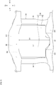
Fig. 4 is a left side view of the driving device unit of the vehicle inFig. 1 and a periphery thereof; -
Fig. 5 is a bottom view of the driving device unit of the vehicle inFig. 1 and the periphery thereof; and - Hereinafter, a vehicle according to the present invention will be described with reference to the drawings. Incidentally, the drawings should be seen based on a direction of reference numerals. In the following description, front, rear, left, right, upper, and lower directions are described according a view from an operator. In the drawings, a front side of the vehicle is denoted by Fr, a rear side is denoted by Rr, a left side is denoted by L, a right side is denoted by R, an upper side is denoted by U, and a lower side is denoted by D.
- As shown in
Figs. 1 and2 , a vehicle 1 according to an embodiment of the present invention is formed by avehicle interior 10 and afront room 20 in front of thevehicle interior 10, which are defined by a floor panel 2 and adash panel 3.Front seats 11 andrear seats 12 are provided in thevehicle interior 10. Adriving device unit 30 is provided below the floor panel 2 behind therear seat 12. Thedriving device unit 30 drives a leftrear wheel 5L and a rightrear wheel 5R. That is, in the vehicle 1, the leftrear wheel 5L and the rightrear wheel 5R are driving wheels, and a leftfront wheel 4L and a rightfront wheel 4R are driven wheels. Thefront wheels rear wheels vehicle body frame 50 via suspensions (not shown) supported by respectivesuspension support portions 6. - A
vehicle body frame 50 includes a pair of left andright side members cross members 53 extending in a left-right direction and connecting theside members subframe 54 having a rectangular shape so as to surround thedriving device unit 30. Thesubframe 54 includes a pair ofsub-side members side members front frame member 57 and arear frame member 58 that connect the pair ofsub-side members - A
battery 60 including a plurality ofbattery modules 60a is disposed below thevehicle interior 10. Thebattery 60 is accommodated in abattery case 61 and disposed below the floor panel 2. A center of gravity G1 of thebattery 60 is positioned rearward compared to afront wheel axle 4a connecting theleft front wheel 4L with rightfront wheel 4R, and is positioned forward compared to arear wheel axle 5a connecting the leftrear wheel 5L with the rightrear wheel 5R. In other words, the center of gravity G1 of thebattery 60 is positioned substantially at a center of the vehicle 1 in the front-rear direction. - As shown in
Figs. 3 and4 , thedriving device unit 30 is fixed to arear frame member 58 via arear mounting portion 542, and is fixed to afront frame member 57 via a pair offront mounting portions 541. Thedriving device unit 30 includes adriving device 31 that accommodates a motor MOT as an electric motor and a Power Control Unit (PCU) 32 as an electric motor control unit that controls the motor MOT. Thedriving device 31 is provided with a transmission (not shown), and torque of the motor MOT is transmitted to arear wheel axle 5a via the transmission, and is transmitted from therear wheel axle 5a to therear wheels driving device 31 and the PCU 32 are arranged side by side in a width direction of the vehicle 1 in a top view. - A maximum length L1 of the
driving device unit 30 in the front-rear direction is longer than a maximum distance D1 between thefront frame member 57 and therear frame member 58 of thesubframe 54 in the front-rear direction, and as shown inFIG. 5 , arear end portion 30r of thedriving device unit 30 overlaps therear frame member 58 in a bottom view. Since the maximum length L1 of thedriving device unit 30 in the front-rear direction is longer than the maximum distance D1 between thefront frame member 57 and therear frame member 58 of thesubframe 54 in the front-rear direction, a length of thesubframe 54 in the front-rear direction supporting thedriving device unit 30 can be reduced. Further, since therear end portion 30r of thedriving device unit 30 overlaps therear frame member 58, therear frame member 58 of thesubframe 54 can firmly bear a rear load of thedriving device unit 30. Incidentally, the maximum length L1 of thedriving device unit 30 in the front-rear direction is a length which does not include brackets of thefront mounting portions 541 and therear mounting portion 542. - As shown in
Fig. 4 , thefront mounting portions 541 are positioned in front of therear wheel axle 5a, and therear mount portion 542 is positioned behind therear wheel axle 5a. Thefront mounting portions 541 are positioned upward than therear mounting portion 542. - A center of gravity G2 of the
driving device unit 30 is positioned behind therear wheel axle 5a. Although a rotational axis of the motor MOT is defined as the center of gravity G2 of thedriving device unit 30 inFigs. 1 and4 , the center of gravity G2 of thedriving device unit 30 may deviate from the rotational axis of the motor MOT in practice. - Here, as shown in
Fig. 1 , when a line connecting the center of gravity G1 of thebattery 60 with the center of gravity G2 of thedriving device unit 30 is defined as a first imaginary line PI, the first imaginary line P1 passes above therear wheel axle 5a and below wheelupper end portions 5b of therear wheels Figs. 1 and4 , when a line connecting the front mounting portion 541 (a support center point of the front mounting portion 541) with the rear mounting portion 542 (a support center point of the rear mounting portion 542) is defined as a second imaginary line P2, the second imaginary line P2 passes above therear wheel axle 5a and below the wheelupper end portions 5b of therear wheels rear wheel axle 5a and below the wheelupper end portions 5b of therear wheels upper end portions 5b of therear wheels - Since the first imaginary line P1 and the second imaginary line P2 pass above the
rear wheel axle 5a and below the wheelupper end portions 5b of therear wheels rear wheels rear wheel axle 5a with respect to thedriving device unit 30 in an upper-lower direction is suppressed, and a torque transmission to therear wheel axle 5a can be stabilized. - Further, since the center of gravity G2 of the
driving device unit 30 is positioned behind therear wheel axle 5a, when receiving a reaction force of the torque at the time of forward movement, a downward force is applied to therear mounting portion 542 and acts in a direction in which therear wheels front wheels rear wheels - Further, since the
front mounting portions 541 are higher than therear mounting portion 542 in the upper-lower direction, the first imaginary line P1 intersects the second imaginary line P2. When the first imaginary line P1 is inclined upward toward the rear, the drivingdevice unit 30 attempts to rotate counterclockwise with respect to thebattery 60 at the time of a rear collision, but when the second imaginary line P2 is inclined upward toward the front, the drivingdevice unit 30 attempts to rotate clockwise with respect to thesubframe 54 in the rear-end collision. In this way, the intersection of the first imaginary line P1 and the second imaginary line P2 cancels the force for rotating thedriving device unit 30, so that it is possible to suppress the rotation of thedriving device unit 30 in the rear-end collision. - The center of gravity G2 of the
driving device unit 30 is positioned on the second imaginary line P2. Accordingly, the drivingdevice unit 30 can be held in a well-balanced manner by the front mountingportions 541 and therear mounting portion 542. - Further, as shown in
Figs. 2 and3 , a distance D2 between a left rear suspension support portion 6 (hereinafter also referred to as left rear suspension support portion 6LR) and a right-rear suspension support portion 6 (hereinafter, also referred to as right rear suspension support portion 6RR) in the vehicle width direction is shorter than a length L2 of thebattery case 61 accommodating thebattery 60 in the vehicle width direction and is shorter than a length L3 of thebattery 60 in the vehicle width direction. Accordingly, the load of thebattery 60 can be securely applied to the left and right suspensions. The length L3 of thebattery 60 in the vehicle width direction is a length between a left end portion and a right end portion of an arrangement region ofbattery modules 60a. - Returning to
Fig.1 , anelectrical device unit 80 is provided in thefront room 20. Theelectrical device unit 80 includes a junction box, a charger, a DC-DC converter, and the like, and these electrical devices are accommodated in thefront room 20 in a state of being held by an auxiliary frame (not shown). - As shown in
Fig. 1 in the side view, the center of gravity G3 of theelectrical device unit 80 and the center of gravity G2 of thedriving device unit 30 are positioned above a third imaginary line P3 connecting thefront wheel axle 4a with therear wheel axle 5a. The center of gravity G3 of theelectrical device unit 80 is positioned above the center of gravity G2 of thedriving device unit 30 and the center of gravity G1 of thebattery 60. In addition to the lowering of the center of gravity by disposing thebattery 60 under the floor, by inclining a roll shaft slightly rearward, relative displacement between an occupant and a vehicle body at the time of steering can be suppressed to enable natural turning. Further, a load can be securely applied to therear wheels - A
seating surface 12a of eachrear seat 12 is between the center of gravity G1 of thebattery 60 and therear wheel axle 5a in the front-rear direction of the vehicle 1, and is positioned above the third imaginary line P3 connecting thefront wheel axle 4a with therear wheel axle 5a. A seat back 12b of therear seat 12 is positioned between wheelfront end portions 5c of therear wheels rear wheel axle 5a. Accordingly, it possible to reliably apply the weight of an occupant on therear seat 12 to therear wheels - The above embodiments may be appropriately modified, improved, or the like (without departing from the scope of the appended claims).
Claims (8)
- A vehicle comprising:a vehicle interior (10);a battery (60) provided below the vehicle interior with a floor panel (2) therebetween; anda driving device unit (30) supported by a vehicle frame member (54) via a front mounting portion (541) and a rear mounting portion (542) and configured to receive electric power from the battery (60) to drive a left rear wheel and a right rear wheel, whereina center of gravity (G1) of the battery is positioned forward compared to a rear wheel axle (5a) that connects the left rear wheel with the right rear wheel,a center of gravity (G2) of the driving device unit is positioned rearward compared to the rear wheel axle,the front mounting portion (541) is positioned forward compared to the rear wheel axle,the rear mounting portion (542) is positioned rearward compared to the rear wheel axle,the front mounting portion (541) is positioned above the rear mounting portion (542), anda first imaginary line (P1) and a second imaginary line (P2) pass above the rear wheel axle and below wheel upper end portions (5b) of the left rear wheel and the right rear wheel in a side view, the first imaginary line (P1) being a line connecting the center of gravity (G1) of the battery with the center of gravity (G2) of the driving device unit (30), the second imaginary line (P2) being a line connecting a support center point of the front mounting portion (541) with a support center point of the rear mounting portion (542),wherein the center of gravity (G2) of the driving device unit is positioned on the second imaginary line (P2).
- The vehicle according to claim 1, whereinthe vehicle frame member is a subframe (54) having a rectangular shape so as to surround the driving device unit, anda maximum length (L1) of the driving device unit in a front-rear direction is longer than a maximum distance (D1) between a front frame member and a rear frame member (58) of the subframe in a front-rear direction.
- The vehicle according to claim 2,
wherein a rear end portion (30r) of the driving device unit overlaps the rear frame member in a bottom view. - The vehicle according to any one of claims 1 to 3 further comprising:a left rear suspension support (6LR) portion to which a left rear suspension supporting the left rear wheel is fixed; anda right rear suspension support portion (6RR) to which a right rear suspension supporting the right rear wheel is fixed,wherein a distance (D2) between the left rear suspension support portion and the right rear suspension support portion in a vehicle width direction is smaller than a length (L2) of a battery case accommodating the battery in the vehicle width direction.
- The vehicle according to any one of claims 1 to 4 further comprising:a left rear suspension support portion (6LR) to which a left rear suspension supporting the left rear wheel is fixed; anda right rear suspension support portion (6RR) to which a right rear suspension supporting the right rear wheel is fixed,wherein a distance (D2) between the left rear suspension support portion and the right rear suspension support portion in a vehicle width direction is smaller than a length (L3) of the battery in the vehicle width direction.
- The vehicle according to any one of claims 1 to 5,
wherein front wheels are driven wheels. - The vehicle according to claim 6 further comprising:a front room (20) provided in front of the vehicle interior; andan electrical device unit (80) provided in the front room, whereina center of gravity (G3) of the electrical device unit and the center of gravity (G2) of the driving device unit are positioned above a third imaginary line (P3) connecting the front wheel axle with the rear wheel axle, andthe center of gravity (G3) of the electrical device unit is positioned above the center of gravity (G2) of the driving device unit and the center of gravity (G1) of the battery.
- The vehicle according to claim 6 or 7, whereina seating surface (12a) of a rear seat (12) is between the center of gravity (G1) of the battery and the rear wheel axle and is positioned above a third imaginary line (P3) connecting the front wheel axle with the rear wheel axle, anda seat back (12b) of the rear seat is positioned between wheel front end portions (5c) of the left rear wheel and the right rear wheel in a front-rear direction of the vehicle and the rear wheel axle.
Applications Claiming Priority (1)
| Application Number | Priority Date | Filing Date | Title |
|---|---|---|---|
| JP2018170798A JP6778725B2 (en) | 2018-09-12 | 2018-09-12 | vehicle |
Publications (2)
| Publication Number | Publication Date |
|---|---|
| EP3623192A1 EP3623192A1 (en) | 2020-03-18 |
| EP3623192B1 true EP3623192B1 (en) | 2021-12-15 |
Family
ID=67909296
Family Applications (1)
| Application Number | Title | Priority Date | Filing Date |
|---|---|---|---|
| EP19196319.8A Active EP3623192B1 (en) | 2018-09-12 | 2019-09-10 | Vehicle |
Country Status (4)
| Country | Link |
|---|---|
| US (1) | US11180014B2 (en) |
| EP (1) | EP3623192B1 (en) |
| JP (1) | JP6778725B2 (en) |
| CN (1) | CN110893756B (en) |
Families Citing this family (11)
| Publication number | Priority date | Publication date | Assignee | Title |
|---|---|---|---|---|
| EP3409523A1 (en) * | 2017-05-30 | 2018-12-05 | FLET GmbH | Electric vehicle |
| US12202325B2 (en) * | 2020-03-24 | 2025-01-21 | Hyundai Motor Company | Body for vehicle |
| KR102730519B1 (en) * | 2020-03-24 | 2024-11-13 | 현대자동차주식회사 | Body for vehicle |
| US12447807B2 (en) | 2020-03-24 | 2025-10-21 | Hyundai Motor Company | Body for vehicle and battery reinforcement structure |
| US11518206B2 (en) | 2021-04-28 | 2022-12-06 | Ford Global Technologies, Llc | Configurable vehicle frames and associated methods |
| US11858571B2 (en) | 2021-04-28 | 2024-01-02 | Ford Global Technologies, Llc | Vehicle chassis with interchangeable performance packages and related methods |
| US11866095B2 (en) | 2021-04-28 | 2024-01-09 | Ford Global Technologies, Llc | Multi-position wheel assembly mounts |
| US11938802B2 (en) | 2021-04-28 | 2024-03-26 | Ford Global Technologies, Llc | Electric motorized wheel assemblies |
| US11702162B2 (en) | 2021-04-28 | 2023-07-18 | Ford Global Technologies, Llc | Configurable vehicle chassis and associated methods |
| US11807302B2 (en) | 2021-04-28 | 2023-11-07 | Ford Global Technologies, Llc | Methods and apparatus for scalable vehicle platforms |
| DE102022124154A1 (en) * | 2022-09-20 | 2024-03-21 | Vibracoustic Se | Support structure |
Family Cites Families (33)
| Publication number | Priority date | Publication date | Assignee | Title |
|---|---|---|---|---|
| US4365681A (en) * | 1980-12-22 | 1982-12-28 | General Motors Corporation | Battery support structure |
| JP3294700B2 (en) * | 1994-02-02 | 2002-06-24 | 本田技研工業株式会社 | Electric vehicle battery device |
| JP2001097048A (en) * | 1999-09-28 | 2001-04-10 | Fuji Heavy Ind Ltd | Body structure of electric vehicle |
| US6880856B2 (en) * | 2001-08-23 | 2005-04-19 | General Motors Corporation | Vehicle body configurations |
| JP3940279B2 (en) * | 2001-09-19 | 2007-07-04 | 三菱自動車エンジニアリング株式会社 | Power unit mounting device |
| WO2005030516A1 (en) * | 2003-09-29 | 2005-04-07 | Nissan Motor Co., Ltd. | Drive motor fixing structure and fixing method |
| JP5125769B2 (en) * | 2008-05-30 | 2013-01-23 | マツダ株式会社 | Electric vehicle body structure |
| US10476051B2 (en) * | 2009-04-22 | 2019-11-12 | Tesla, Inc. | Battery pack base plate heat exchanger |
| DE102009033531A1 (en) * | 2009-07-10 | 2011-01-20 | Dr. Ing. H.C. F. Porsche Aktiengesellschaft | Drive device for a motor vehicle with an electric machine having portal axis |
| US20110079454A1 (en) * | 2009-10-07 | 2011-04-07 | Gm Global Technology Operations, Inc. | Hybrid vehicle configuration and method of reconfiguring non-hybrid vehicle architecture as hybrid vehicle architecture |
| US20110094807A1 (en) * | 2009-10-26 | 2011-04-28 | Steve Pruitt | Electric drive system for passive vehicle |
| JP5115543B2 (en) * | 2009-12-03 | 2013-01-09 | 三菱自動車工業株式会社 | Installation structure of electric motor for hybrid vehicle |
| DE102010017966A1 (en) * | 2010-04-23 | 2011-10-27 | Dr. Ing. H.C. F. Porsche Aktiengesellschaft | Vehicle with electric drive |
| JP5656032B2 (en) | 2010-08-03 | 2015-01-21 | 三菱自動車工業株式会社 | Vehicle rear protection structure |
| JP5541051B2 (en) * | 2010-09-30 | 2014-07-09 | マツダ株式会社 | Electric vehicle motor mounting structure |
| US20120161472A1 (en) * | 2010-12-22 | 2012-06-28 | Tesla Motors, Inc. | System for Absorbing and Distributing Side Impact Energy Utilizing an Integrated Battery Pack |
| US8585131B2 (en) * | 2011-01-05 | 2013-11-19 | Tesla Motors, Inc. | Rear vehicle torque box |
| JP5737119B2 (en) * | 2011-10-06 | 2015-06-17 | 三菱自動車工業株式会社 | Body structure |
| JP5870457B2 (en) * | 2012-11-08 | 2016-03-01 | 本田技研工業株式会社 | Electric vehicle |
| US10131381B2 (en) * | 2015-06-30 | 2018-11-20 | Faraday & Future Inc. | Joint for an underbody of a motor vehicle |
| WO2017008783A1 (en) * | 2015-07-10 | 2017-01-19 | Ksm Castings Group Gmbh | Auxiliary frame for motor vehicles |
| WO2017017762A1 (en) * | 2015-07-27 | 2017-02-02 | 本田技研工業株式会社 | Vehicle |
| JP6237749B2 (en) * | 2015-11-11 | 2017-11-29 | マツダ株式会社 | Rear subframe structure |
| JP6605347B2 (en) * | 2016-02-04 | 2019-11-13 | 本田技研工業株式会社 | 4 wheel vehicle |
| JP6451685B2 (en) * | 2016-04-21 | 2019-01-16 | トヨタ自動車株式会社 | Vehicle battery mounting structure |
| US10581126B2 (en) * | 2016-05-09 | 2020-03-03 | Nikola Corporation | Electric battery assembly |
| US10173464B2 (en) * | 2016-06-12 | 2019-01-08 | Monolithic 3D, Inc. | Efficient wheel |
| US10843679B2 (en) * | 2016-06-12 | 2020-11-24 | Or-Ment Llc | Electrical passenger car with efficient wheels |
| US20180105062A1 (en) * | 2016-10-14 | 2018-04-19 | Inevit, Inc. | Battery module compartment chamber and battery module mounting area of an energy storage system and method thereof |
| JP6631472B2 (en) * | 2016-11-07 | 2020-01-15 | トヨタ自動車株式会社 | Vehicle undercarriage |
| EP3409523A1 (en) * | 2017-05-30 | 2018-12-05 | FLET GmbH | Electric vehicle |
| JP7006390B2 (en) * | 2018-03-09 | 2022-01-24 | トヨタ自動車株式会社 | Vehicle lower body structure |
| EP3539810A1 (en) * | 2018-03-13 | 2019-09-18 | FCA Italy S.p.A. | Electric vehicle with a modular structure |
-
2018
- 2018-09-12 JP JP2018170798A patent/JP6778725B2/en active Active
-
2019
- 2019-09-09 US US16/564,455 patent/US11180014B2/en active Active
- 2019-09-10 EP EP19196319.8A patent/EP3623192B1/en active Active
- 2019-09-10 CN CN201910856172.1A patent/CN110893756B/en active Active
Also Published As
| Publication number | Publication date |
|---|---|
| JP2020040575A (en) | 2020-03-19 |
| US20200079201A1 (en) | 2020-03-12 |
| JP6778725B2 (en) | 2020-11-04 |
| CN110893756B (en) | 2023-05-09 |
| US11180014B2 (en) | 2021-11-23 |
| EP3623192A1 (en) | 2020-03-18 |
| CN110893756A (en) | 2020-03-20 |
Similar Documents
| Publication | Publication Date | Title |
|---|---|---|
| EP3623192B1 (en) | Vehicle | |
| EP3623194A1 (en) | Vehicle | |
| JP6718935B2 (en) | vehicle | |
| JP5573196B2 (en) | Front body structure of the vehicle | |
| CN111516620A (en) | vehicle | |
| JPWO2012017935A1 (en) | Vehicle rear protection structure | |
| CN219634967U (en) | Vehicle substructure for an at least partially electrically driven motor vehicle | |
| CN108367660A (en) | The loading structure of high voltage control device unit | |
| US12030374B2 (en) | Bearing arrangement of a component on an axle carrier for a motor vehicle, and motor vehicle, in particular passenger car | |
| WO2021145056A1 (en) | Layout structure of power source unit in electric vehicle | |
| JP2012121375A (en) | Battery arrangement structure of vehicle | |
| JP7647600B2 (en) | Electric vehicles | |
| JP7397020B2 (en) | vehicle | |
| JP2019077355A (en) | On-vehicle structure of power control device | |
| JP6694484B2 (en) | vehicle | |
| JP2020192878A (en) | vehicle | |
| JP7759557B2 (en) | Vehicle undercarriage | |
| WO2019207879A1 (en) | Electric vehicle | |
| JP7461738B2 (en) | vehicle | |
| JPH11115516A (en) | Electric car | |
| JP2022082936A (en) | vehicle | |
| JP5532876B2 (en) | Vehicle battery arrangement structure | |
| US20240157818A1 (en) | Work Vehicle | |
| JP7650686B2 (en) | vehicle | |
| US20240157775A1 (en) | Work Vehicle |
Legal Events
| Date | Code | Title | Description |
|---|---|---|---|
| PUAI | Public reference made under article 153(3) epc to a published international application that has entered the european phase |
Free format text: ORIGINAL CODE: 0009012 |
|
| STAA | Information on the status of an ep patent application or granted ep patent |
Free format text: STATUS: REQUEST FOR EXAMINATION WAS MADE |
|
| 17P | Request for examination filed |
Effective date: 20190910 |
|
| AK | Designated contracting states |
Kind code of ref document: A1 Designated state(s): AL AT BE BG CH CY CZ DE DK EE ES FI FR GB GR HR HU IE IS IT LI LT LU LV MC MK MT NL NO PL PT RO RS SE SI SK SM TR |
|
| AX | Request for extension of the european patent |
Extension state: BA ME |
|
| STAA | Information on the status of an ep patent application or granted ep patent |
Free format text: STATUS: EXAMINATION IS IN PROGRESS |
|
| 17Q | First examination report despatched |
Effective date: 20210113 |
|
| GRAP | Despatch of communication of intention to grant a patent |
Free format text: ORIGINAL CODE: EPIDOSNIGR1 |
|
| STAA | Information on the status of an ep patent application or granted ep patent |
Free format text: STATUS: GRANT OF PATENT IS INTENDED |
|
| INTG | Intention to grant announced |
Effective date: 20210715 |
|
| GRAS | Grant fee paid |
Free format text: ORIGINAL CODE: EPIDOSNIGR3 |
|
| GRAA | (expected) grant |
Free format text: ORIGINAL CODE: 0009210 |
|
| STAA | Information on the status of an ep patent application or granted ep patent |
Free format text: STATUS: THE PATENT HAS BEEN GRANTED |
|
| AK | Designated contracting states |
Kind code of ref document: B1 Designated state(s): AL AT BE BG CH CY CZ DE DK EE ES FI FR GB GR HR HU IE IS IT LI LT LU LV MC MK MT NL NO PL PT RO RS SE SI SK SM TR |
|
| REG | Reference to a national code |
Ref country code: GB Ref legal event code: FG4D Ref country code: CH Ref legal event code: EP |
|
| REG | Reference to a national code |
Ref country code: IE Ref legal event code: FG4D Ref country code: DE Ref legal event code: R096 Ref document number: 602019010052 Country of ref document: DE |
|
| REG | Reference to a national code |
Ref country code: AT Ref legal event code: REF Ref document number: 1455230 Country of ref document: AT Kind code of ref document: T Effective date: 20220115 |
|
| REG | Reference to a national code |
Ref country code: LT Ref legal event code: MG9D |
|
| REG | Reference to a national code |
Ref country code: NL Ref legal event code: MP Effective date: 20211215 |
|
| PG25 | Lapsed in a contracting state [announced via postgrant information from national office to epo] |
Ref country code: RS Free format text: LAPSE BECAUSE OF FAILURE TO SUBMIT A TRANSLATION OF THE DESCRIPTION OR TO PAY THE FEE WITHIN THE PRESCRIBED TIME-LIMIT Effective date: 20211215 Ref country code: LT Free format text: LAPSE BECAUSE OF FAILURE TO SUBMIT A TRANSLATION OF THE DESCRIPTION OR TO PAY THE FEE WITHIN THE PRESCRIBED TIME-LIMIT Effective date: 20211215 Ref country code: FI Free format text: LAPSE BECAUSE OF FAILURE TO SUBMIT A TRANSLATION OF THE DESCRIPTION OR TO PAY THE FEE WITHIN THE PRESCRIBED TIME-LIMIT Effective date: 20211215 Ref country code: BG Free format text: LAPSE BECAUSE OF FAILURE TO SUBMIT A TRANSLATION OF THE DESCRIPTION OR TO PAY THE FEE WITHIN THE PRESCRIBED TIME-LIMIT Effective date: 20220315 |
|
| REG | Reference to a national code |
Ref country code: AT Ref legal event code: MK05 Ref document number: 1455230 Country of ref document: AT Kind code of ref document: T Effective date: 20211215 |
|
| PG25 | Lapsed in a contracting state [announced via postgrant information from national office to epo] |
Ref country code: SE Free format text: LAPSE BECAUSE OF FAILURE TO SUBMIT A TRANSLATION OF THE DESCRIPTION OR TO PAY THE FEE WITHIN THE PRESCRIBED TIME-LIMIT Effective date: 20211215 Ref country code: NO Free format text: LAPSE BECAUSE OF FAILURE TO SUBMIT A TRANSLATION OF THE DESCRIPTION OR TO PAY THE FEE WITHIN THE PRESCRIBED TIME-LIMIT Effective date: 20220315 Ref country code: LV Free format text: LAPSE BECAUSE OF FAILURE TO SUBMIT A TRANSLATION OF THE DESCRIPTION OR TO PAY THE FEE WITHIN THE PRESCRIBED TIME-LIMIT Effective date: 20211215 Ref country code: HR Free format text: LAPSE BECAUSE OF FAILURE TO SUBMIT A TRANSLATION OF THE DESCRIPTION OR TO PAY THE FEE WITHIN THE PRESCRIBED TIME-LIMIT Effective date: 20211215 Ref country code: GR Free format text: LAPSE BECAUSE OF FAILURE TO SUBMIT A TRANSLATION OF THE DESCRIPTION OR TO PAY THE FEE WITHIN THE PRESCRIBED TIME-LIMIT Effective date: 20220316 |
|
| PG25 | Lapsed in a contracting state [announced via postgrant information from national office to epo] |
Ref country code: NL Free format text: LAPSE BECAUSE OF FAILURE TO SUBMIT A TRANSLATION OF THE DESCRIPTION OR TO PAY THE FEE WITHIN THE PRESCRIBED TIME-LIMIT Effective date: 20211215 |
|
| PG25 | Lapsed in a contracting state [announced via postgrant information from national office to epo] |
Ref country code: SM Free format text: LAPSE BECAUSE OF FAILURE TO SUBMIT A TRANSLATION OF THE DESCRIPTION OR TO PAY THE FEE WITHIN THE PRESCRIBED TIME-LIMIT Effective date: 20211215 Ref country code: SK Free format text: LAPSE BECAUSE OF FAILURE TO SUBMIT A TRANSLATION OF THE DESCRIPTION OR TO PAY THE FEE WITHIN THE PRESCRIBED TIME-LIMIT Effective date: 20211215 Ref country code: RO Free format text: LAPSE BECAUSE OF FAILURE TO SUBMIT A TRANSLATION OF THE DESCRIPTION OR TO PAY THE FEE WITHIN THE PRESCRIBED TIME-LIMIT Effective date: 20211215 Ref country code: PT Free format text: LAPSE BECAUSE OF FAILURE TO SUBMIT A TRANSLATION OF THE DESCRIPTION OR TO PAY THE FEE WITHIN THE PRESCRIBED TIME-LIMIT Effective date: 20220418 Ref country code: ES Free format text: LAPSE BECAUSE OF FAILURE TO SUBMIT A TRANSLATION OF THE DESCRIPTION OR TO PAY THE FEE WITHIN THE PRESCRIBED TIME-LIMIT Effective date: 20211215 Ref country code: EE Free format text: LAPSE BECAUSE OF FAILURE TO SUBMIT A TRANSLATION OF THE DESCRIPTION OR TO PAY THE FEE WITHIN THE PRESCRIBED TIME-LIMIT Effective date: 20211215 Ref country code: CZ Free format text: LAPSE BECAUSE OF FAILURE TO SUBMIT A TRANSLATION OF THE DESCRIPTION OR TO PAY THE FEE WITHIN THE PRESCRIBED TIME-LIMIT Effective date: 20211215 |
|
| REG | Reference to a national code |
Ref country code: DE Ref legal event code: R084 Ref document number: 602019010052 Country of ref document: DE |
|
| PG25 | Lapsed in a contracting state [announced via postgrant information from national office to epo] |
Ref country code: PL Free format text: LAPSE BECAUSE OF FAILURE TO SUBMIT A TRANSLATION OF THE DESCRIPTION OR TO PAY THE FEE WITHIN THE PRESCRIBED TIME-LIMIT Effective date: 20211215 Ref country code: AT Free format text: LAPSE BECAUSE OF FAILURE TO SUBMIT A TRANSLATION OF THE DESCRIPTION OR TO PAY THE FEE WITHIN THE PRESCRIBED TIME-LIMIT Effective date: 20211215 |
|
| REG | Reference to a national code |
Ref country code: DE Ref legal event code: R097 Ref document number: 602019010052 Country of ref document: DE |
|
| PG25 | Lapsed in a contracting state [announced via postgrant information from national office to epo] |
Ref country code: IS Free format text: LAPSE BECAUSE OF FAILURE TO SUBMIT A TRANSLATION OF THE DESCRIPTION OR TO PAY THE FEE WITHIN THE PRESCRIBED TIME-LIMIT Effective date: 20220415 |
|
| PLBE | No opposition filed within time limit |
Free format text: ORIGINAL CODE: 0009261 |
|
| STAA | Information on the status of an ep patent application or granted ep patent |
Free format text: STATUS: NO OPPOSITION FILED WITHIN TIME LIMIT |
|
| PG25 | Lapsed in a contracting state [announced via postgrant information from national office to epo] |
Ref country code: DK Free format text: LAPSE BECAUSE OF FAILURE TO SUBMIT A TRANSLATION OF THE DESCRIPTION OR TO PAY THE FEE WITHIN THE PRESCRIBED TIME-LIMIT Effective date: 20211215 Ref country code: AL Free format text: LAPSE BECAUSE OF FAILURE TO SUBMIT A TRANSLATION OF THE DESCRIPTION OR TO PAY THE FEE WITHIN THE PRESCRIBED TIME-LIMIT Effective date: 20211215 |
|
| 26N | No opposition filed |
Effective date: 20220916 |
|
| PG25 | Lapsed in a contracting state [announced via postgrant information from national office to epo] |
Ref country code: SI Free format text: LAPSE BECAUSE OF FAILURE TO SUBMIT A TRANSLATION OF THE DESCRIPTION OR TO PAY THE FEE WITHIN THE PRESCRIBED TIME-LIMIT Effective date: 20211215 |
|
| PG25 | Lapsed in a contracting state [announced via postgrant information from national office to epo] |
Ref country code: MC Free format text: LAPSE BECAUSE OF FAILURE TO SUBMIT A TRANSLATION OF THE DESCRIPTION OR TO PAY THE FEE WITHIN THE PRESCRIBED TIME-LIMIT Effective date: 20211215 |
|
| REG | Reference to a national code |
Ref country code: CH Ref legal event code: PL |
|
| REG | Reference to a national code |
Ref country code: BE Ref legal event code: MM Effective date: 20220930 |
|
| PG25 | Lapsed in a contracting state [announced via postgrant information from national office to epo] |
Ref country code: IT Free format text: LAPSE BECAUSE OF FAILURE TO SUBMIT A TRANSLATION OF THE DESCRIPTION OR TO PAY THE FEE WITHIN THE PRESCRIBED TIME-LIMIT Effective date: 20211215 |
|
| PG25 | Lapsed in a contracting state [announced via postgrant information from national office to epo] |
Ref country code: LU Free format text: LAPSE BECAUSE OF NON-PAYMENT OF DUE FEES Effective date: 20220910 |
|
| PG25 | Lapsed in a contracting state [announced via postgrant information from national office to epo] |
Ref country code: LI Free format text: LAPSE BECAUSE OF NON-PAYMENT OF DUE FEES Effective date: 20220930 Ref country code: IE Free format text: LAPSE BECAUSE OF NON-PAYMENT OF DUE FEES Effective date: 20220910 Ref country code: FR Free format text: LAPSE BECAUSE OF NON-PAYMENT OF DUE FEES Effective date: 20220930 Ref country code: CH Free format text: LAPSE BECAUSE OF NON-PAYMENT OF DUE FEES Effective date: 20220930 |
|
| PG25 | Lapsed in a contracting state [announced via postgrant information from national office to epo] |
Ref country code: BE Free format text: LAPSE BECAUSE OF NON-PAYMENT OF DUE FEES Effective date: 20220930 |
|
| PG25 | Lapsed in a contracting state [announced via postgrant information from national office to epo] |
Ref country code: HU Free format text: LAPSE BECAUSE OF FAILURE TO SUBMIT A TRANSLATION OF THE DESCRIPTION OR TO PAY THE FEE WITHIN THE PRESCRIBED TIME-LIMIT; INVALID AB INITIO Effective date: 20190910 |
|
| PG25 | Lapsed in a contracting state [announced via postgrant information from national office to epo] |
Ref country code: CY Free format text: LAPSE BECAUSE OF FAILURE TO SUBMIT A TRANSLATION OF THE DESCRIPTION OR TO PAY THE FEE WITHIN THE PRESCRIBED TIME-LIMIT Effective date: 20211215 |
|
| GBPC | Gb: european patent ceased through non-payment of renewal fee |
Effective date: 20230910 |
|
| PG25 | Lapsed in a contracting state [announced via postgrant information from national office to epo] |
Ref country code: MK Free format text: LAPSE BECAUSE OF FAILURE TO SUBMIT A TRANSLATION OF THE DESCRIPTION OR TO PAY THE FEE WITHIN THE PRESCRIBED TIME-LIMIT Effective date: 20211215 |
|
| PG25 | Lapsed in a contracting state [announced via postgrant information from national office to epo] |
Ref country code: GB Free format text: LAPSE BECAUSE OF NON-PAYMENT OF DUE FEES Effective date: 20230910 |
|
| PG25 | Lapsed in a contracting state [announced via postgrant information from national office to epo] |
Ref country code: GB Free format text: LAPSE BECAUSE OF NON-PAYMENT OF DUE FEES Effective date: 20230910 |
|
| PG25 | Lapsed in a contracting state [announced via postgrant information from national office to epo] |
Ref country code: MT Free format text: LAPSE BECAUSE OF FAILURE TO SUBMIT A TRANSLATION OF THE DESCRIPTION OR TO PAY THE FEE WITHIN THE PRESCRIBED TIME-LIMIT Effective date: 20211215 |
|
| PGFP | Annual fee paid to national office [announced via postgrant information from national office to epo] |
Ref country code: DE Payment date: 20250820 Year of fee payment: 7 |
|
| PG25 | Lapsed in a contracting state [announced via postgrant information from national office to epo] |
Ref country code: TR Free format text: LAPSE BECAUSE OF FAILURE TO SUBMIT A TRANSLATION OF THE DESCRIPTION OR TO PAY THE FEE WITHIN THE PRESCRIBED TIME-LIMIT Effective date: 20211215 |